EP3227409B1 - Cuve de décapage pour éliminer les hydrocarbures entraînés dans des particules de catalyseur - Google Patents
Cuve de décapage pour éliminer les hydrocarbures entraînés dans des particules de catalyseur Download PDFInfo
- Publication number
- EP3227409B1 EP3227409B1 EP15866041.5A EP15866041A EP3227409B1 EP 3227409 B1 EP3227409 B1 EP 3227409B1 EP 15866041 A EP15866041 A EP 15866041A EP 3227409 B1 EP3227409 B1 EP 3227409B1
- Authority
- EP
- European Patent Office
- Prior art keywords
- stripping
- catalyst
- grid
- stripping section
- vessel
- Prior art date
- Legal status (The legal status is an assumption and is not a legal conclusion. Google has not performed a legal analysis and makes no representation as to the accuracy of the status listed.)
- Active
Links
- 239000003054 catalyst Substances 0.000 title claims description 141
- 229930195733 hydrocarbon Natural products 0.000 title claims description 40
- 150000002430 hydrocarbons Chemical class 0.000 title claims description 40
- 239000002245 particle Substances 0.000 title claims description 31
- 238000012856 packing Methods 0.000 claims description 30
- 238000000034 method Methods 0.000 claims description 29
- 230000008569 process Effects 0.000 claims description 27
- 239000012530 fluid Substances 0.000 claims description 15
- 230000001419 dependent effect Effects 0.000 claims description 3
- 238000006243 chemical reaction Methods 0.000 description 35
- 238000004231 fluid catalytic cracking Methods 0.000 description 25
- 230000008929 regeneration Effects 0.000 description 23
- 238000011069 regeneration method Methods 0.000 description 23
- 239000000571 coke Substances 0.000 description 17
- 239000007789 gas Substances 0.000 description 17
- 239000004215 Carbon black (E152) Substances 0.000 description 9
- 239000000203 mixture Substances 0.000 description 8
- 238000009825 accumulation Methods 0.000 description 7
- 238000013461 design Methods 0.000 description 6
- 239000003921 oil Substances 0.000 description 6
- 230000032258 transport Effects 0.000 description 6
- JTJMJGYZQZDUJJ-UHFFFAOYSA-N phencyclidine Chemical class C1CCCCN1C1(C=2C=CC=CC=2)CCCCC1 JTJMJGYZQZDUJJ-UHFFFAOYSA-N 0.000 description 5
- 238000009826 distribution Methods 0.000 description 4
- 239000001257 hydrogen Substances 0.000 description 4
- 229910052739 hydrogen Inorganic materials 0.000 description 4
- 238000000926 separation method Methods 0.000 description 4
- QVGXLLKOCUKJST-UHFFFAOYSA-N atomic oxygen Chemical compound [O] QVGXLLKOCUKJST-UHFFFAOYSA-N 0.000 description 3
- 238000005336 cracking Methods 0.000 description 3
- 230000000694 effects Effects 0.000 description 3
- 238000005243 fluidization Methods 0.000 description 3
- 229910052760 oxygen Inorganic materials 0.000 description 3
- 239000001301 oxygen Substances 0.000 description 3
- 230000001105 regulatory effect Effects 0.000 description 3
- 230000000630 rising effect Effects 0.000 description 3
- 239000007787 solid Substances 0.000 description 3
- IJGRMHOSHXDMSA-UHFFFAOYSA-N Atomic nitrogen Chemical compound N#N IJGRMHOSHXDMSA-UHFFFAOYSA-N 0.000 description 2
- OKTJSMMVPCPJKN-UHFFFAOYSA-N Carbon Chemical compound [C] OKTJSMMVPCPJKN-UHFFFAOYSA-N 0.000 description 2
- CURLTUGMZLYLDI-UHFFFAOYSA-N Carbon dioxide Chemical compound O=C=O CURLTUGMZLYLDI-UHFFFAOYSA-N 0.000 description 2
- UGFAIRIUMAVXCW-UHFFFAOYSA-N Carbon monoxide Chemical compound [O+]#[C-] UGFAIRIUMAVXCW-UHFFFAOYSA-N 0.000 description 2
- UFHFLCQGNIYNRP-UHFFFAOYSA-N Hydrogen Chemical compound [H][H] UFHFLCQGNIYNRP-UHFFFAOYSA-N 0.000 description 2
- IMNFDUFMRHMDMM-UHFFFAOYSA-N N-Heptane Chemical compound CCCCCCC IMNFDUFMRHMDMM-UHFFFAOYSA-N 0.000 description 2
- 238000009835 boiling Methods 0.000 description 2
- 229910052799 carbon Inorganic materials 0.000 description 2
- 230000003197 catalytic effect Effects 0.000 description 2
- 230000006835 compression Effects 0.000 description 2
- 238000007906 compression Methods 0.000 description 2
- 239000010779 crude oil Substances 0.000 description 2
- 238000005194 fractionation Methods 0.000 description 2
- 230000003116 impacting effect Effects 0.000 description 2
- 239000000463 material Substances 0.000 description 2
- 239000011236 particulate material Substances 0.000 description 2
- 239000011148 porous material Substances 0.000 description 2
- 238000012545 processing Methods 0.000 description 2
- 230000000087 stabilizing effect Effects 0.000 description 2
- 238000012546 transfer Methods 0.000 description 2
- NINIDFKCEFEMDL-UHFFFAOYSA-N Sulfur Chemical compound [S] NINIDFKCEFEMDL-UHFFFAOYSA-N 0.000 description 1
- 229910021536 Zeolite Inorganic materials 0.000 description 1
- 229910002092 carbon dioxide Inorganic materials 0.000 description 1
- 239000001569 carbon dioxide Substances 0.000 description 1
- 229910002091 carbon monoxide Inorganic materials 0.000 description 1
- 238000004523 catalytic cracking Methods 0.000 description 1
- 230000005465 channeling Effects 0.000 description 1
- 238000002485 combustion reaction Methods 0.000 description 1
- HNPSIPDUKPIQMN-UHFFFAOYSA-N dioxosilane;oxo(oxoalumanyloxy)alumane Chemical compound O=[Si]=O.O=[Al]O[Al]=O HNPSIPDUKPIQMN-UHFFFAOYSA-N 0.000 description 1
- 239000000839 emulsion Substances 0.000 description 1
- 239000003546 flue gas Substances 0.000 description 1
- 150000002431 hydrogen Chemical class 0.000 description 1
- 238000002347 injection Methods 0.000 description 1
- 239000007924 injection Substances 0.000 description 1
- 238000004519 manufacturing process Methods 0.000 description 1
- 229910052751 metal Inorganic materials 0.000 description 1
- 239000002184 metal Substances 0.000 description 1
- VUZPPFZMUPKLLV-UHFFFAOYSA-N methane;hydrate Chemical compound C.O VUZPPFZMUPKLLV-UHFFFAOYSA-N 0.000 description 1
- 229910052757 nitrogen Inorganic materials 0.000 description 1
- 230000003647 oxidation Effects 0.000 description 1
- 238000007254 oxidation reaction Methods 0.000 description 1
- 239000003208 petroleum Substances 0.000 description 1
- 230000009467 reduction Effects 0.000 description 1
- 238000007670 refining Methods 0.000 description 1
- 230000000717 retained effect Effects 0.000 description 1
- 239000000243 solution Substances 0.000 description 1
- 238000004901 spalling Methods 0.000 description 1
- 239000000126 substance Substances 0.000 description 1
- 229910052717 sulfur Inorganic materials 0.000 description 1
- 239000011593 sulfur Substances 0.000 description 1
- 238000010998 test method Methods 0.000 description 1
- XLYOFNOQVPJJNP-UHFFFAOYSA-N water Substances O XLYOFNOQVPJJNP-UHFFFAOYSA-N 0.000 description 1
- 229910001868 water Inorganic materials 0.000 description 1
- 239000010457 zeolite Substances 0.000 description 1
Images

Classifications
-
- B—PERFORMING OPERATIONS; TRANSPORTING
- B01—PHYSICAL OR CHEMICAL PROCESSES OR APPARATUS IN GENERAL
- B01J—CHEMICAL OR PHYSICAL PROCESSES, e.g. CATALYSIS OR COLLOID CHEMISTRY; THEIR RELEVANT APPARATUS
- B01J38/00—Regeneration or reactivation of catalysts, in general
- B01J38/04—Gas or vapour treating; Treating by using liquids vaporisable upon contacting spent catalyst
- B01J38/06—Gas or vapour treating; Treating by using liquids vaporisable upon contacting spent catalyst using steam
-
- B—PERFORMING OPERATIONS; TRANSPORTING
- B01—PHYSICAL OR CHEMICAL PROCESSES OR APPARATUS IN GENERAL
- B01J—CHEMICAL OR PHYSICAL PROCESSES, e.g. CATALYSIS OR COLLOID CHEMISTRY; THEIR RELEVANT APPARATUS
- B01J29/00—Catalysts comprising molecular sieves
- B01J29/90—Regeneration or reactivation
-
- B—PERFORMING OPERATIONS; TRANSPORTING
- B01—PHYSICAL OR CHEMICAL PROCESSES OR APPARATUS IN GENERAL
- B01J—CHEMICAL OR PHYSICAL PROCESSES, e.g. CATALYSIS OR COLLOID CHEMISTRY; THEIR RELEVANT APPARATUS
- B01J8/00—Chemical or physical processes in general, conducted in the presence of fluids and solid particles; Apparatus for such processes
- B01J8/18—Chemical or physical processes in general, conducted in the presence of fluids and solid particles; Apparatus for such processes with fluidised particles
- B01J8/24—Chemical or physical processes in general, conducted in the presence of fluids and solid particles; Apparatus for such processes with fluidised particles according to "fluidised-bed" technique
- B01J8/26—Chemical or physical processes in general, conducted in the presence of fluids and solid particles; Apparatus for such processes with fluidised particles according to "fluidised-bed" technique with two or more fluidised beds, e.g. reactor and regeneration installations
-
- B—PERFORMING OPERATIONS; TRANSPORTING
- B01—PHYSICAL OR CHEMICAL PROCESSES OR APPARATUS IN GENERAL
- B01J—CHEMICAL OR PHYSICAL PROCESSES, e.g. CATALYSIS OR COLLOID CHEMISTRY; THEIR RELEVANT APPARATUS
- B01J8/00—Chemical or physical processes in general, conducted in the presence of fluids and solid particles; Apparatus for such processes
- B01J8/18—Chemical or physical processes in general, conducted in the presence of fluids and solid particles; Apparatus for such processes with fluidised particles
- B01J8/24—Chemical or physical processes in general, conducted in the presence of fluids and solid particles; Apparatus for such processes with fluidised particles according to "fluidised-bed" technique
- B01J8/34—Chemical or physical processes in general, conducted in the presence of fluids and solid particles; Apparatus for such processes with fluidised particles according to "fluidised-bed" technique with stationary packing material in the fluidised bed, e.g. bricks, wire rings, baffles
-
- B—PERFORMING OPERATIONS; TRANSPORTING
- B01—PHYSICAL OR CHEMICAL PROCESSES OR APPARATUS IN GENERAL
- B01J—CHEMICAL OR PHYSICAL PROCESSES, e.g. CATALYSIS OR COLLOID CHEMISTRY; THEIR RELEVANT APPARATUS
- B01J2208/00—Processes carried out in the presence of solid particles; Reactors therefor
- B01J2208/00743—Feeding or discharging of solids
- B01J2208/00752—Feeding
-
- B—PERFORMING OPERATIONS; TRANSPORTING
- B01—PHYSICAL OR CHEMICAL PROCESSES OR APPARATUS IN GENERAL
- B01J—CHEMICAL OR PHYSICAL PROCESSES, e.g. CATALYSIS OR COLLOID CHEMISTRY; THEIR RELEVANT APPARATUS
- B01J2208/00—Processes carried out in the presence of solid particles; Reactors therefor
- B01J2208/00743—Feeding or discharging of solids
- B01J2208/00761—Discharging
-
- B—PERFORMING OPERATIONS; TRANSPORTING
- B01—PHYSICAL OR CHEMICAL PROCESSES OR APPARATUS IN GENERAL
- B01J—CHEMICAL OR PHYSICAL PROCESSES, e.g. CATALYSIS OR COLLOID CHEMISTRY; THEIR RELEVANT APPARATUS
- B01J2219/00—Chemical, physical or physico-chemical processes in general; Their relevant apparatus
- B01J2219/32—Details relating to packing elements in the form of grids or built-up elements for forming a unit of module inside the apparatus for mass or heat transfer
- B01J2219/322—Basic shape of the elements
- B01J2219/32203—Sheets
- B01J2219/3221—Corrugated sheets
-
- B—PERFORMING OPERATIONS; TRANSPORTING
- B01—PHYSICAL OR CHEMICAL PROCESSES OR APPARATUS IN GENERAL
- B01J—CHEMICAL OR PHYSICAL PROCESSES, e.g. CATALYSIS OR COLLOID CHEMISTRY; THEIR RELEVANT APPARATUS
- B01J2219/00—Chemical, physical or physico-chemical processes in general; Their relevant apparatus
- B01J2219/32—Details relating to packing elements in the form of grids or built-up elements for forming a unit of module inside the apparatus for mass or heat transfer
- B01J2219/322—Basic shape of the elements
- B01J2219/32203—Sheets
- B01J2219/32237—Sheets comprising apertures or perforations
- B01J2219/32241—Louvres
Definitions
- This invention relates generally to a vessel used to recover hydrocarbons from a catalyst, and more particularly to a vessel use to recover hydrocarbons entrained in a catalyst and a process for recovering same.
- a variety of processes contact finely divided particulate material with a hydrocarbon containing feed under conditions wherein a fluid maintains the particles in a fluidized condition to effect transport of the solid particles to different stages of the process.
- Fluid catalytic cracking is a prime example of such a process that contacts hydrocarbons in a reaction zone with a catalyst composed of finely divided particulate material.
- the hydrocarbon feed fluidizes the catalyst and typically transports it in a riser as the catalyst promotes the cracking reaction.
- substantial amounts of hydrocarbon called coke, are deposited on the catalyst.
- a high temperature regeneration typically within a regeneration zone, burns coke from the catalyst by contacting the catalyst with an oxygen-containing stream that again serves as a fluidization medium.
- Coke-containing catalyst referred to herein as spent catalyst, is continually removed from the reaction zone and replaced by essentially coke-free catalyst from the regeneration zone. Fluidization of the catalyst particles by various gaseous streams allows the transport of catalyst between the reaction zone and regeneration zone.
- a majority of the hydrocarbon vapors that contact the catalyst in the reaction zone are separated from the solid particles by various separation methods within the reaction zone such as ballistic and/or centrifugal separation.
- the catalyst particles employed in FCC processes typically have a large surface area, which is due to a great multitude of pores located in the particles.
- the catalytic materials may retain hydrocarbons within their pores, upon the external surface of the catalyst, as well as within the spaces between individual catalyst particles.
- the quantity of hydrocarbons retained on each individual catalyst particle may be very small, the vast amount of catalyst and the high catalyst circulation rate which is typically used in modem FCC processes results in a significant quantity of hydrocarbons being withdrawn from the reaction zone with the catalyst.
- Delta coke is the weight percent of the coke on spent catalyst less the weight percent of the coke on regenerated catalyst. Reducing delta coke in the FCC process causes a lowering of the regenerator temperature. Consequently, more of the resulting, relatively cooler regenerated catalyst is required to supply the fixed heat load in the reaction zone.
- the reaction zone may hence operate at a higher catalyst-to-feed or catalyst-to-oil (C/O) ratio. The higher C/O ratio increases conversion which increases the production of valuable products.
- C/O catalyst-to-oil
- the most common method of stripping hydrocarbons from the catalyst utilizes a stripping gas, usually steam, passed through a stream of catalyst, counter-current to the direction of flow of the catalyst.
- a stripping gas usually steam
- Such steam stripping operations with varying degrees of efficiency, remove the hydrocarbon vapors which are entrained with the catalyst and adsorbed on the catalyst.
- a refiner or processor may utilized newer designs for internal equipment within existing stripping vessels.
- the use of the existing stripping vessels allows the refiner or processor to minimize capital expenditures while utilizing improvements in the refining and processing industry to increase conversions and yields.
- the over accumulation of catalyst can result in catalyst compression leading to gas bypassing where the rising steam will channel through the stripping vessel without entering into an emulsion phase with the catalyst to remove the entrained hydrocarbons. This leads to a reduction in stripping efficiency and hydraulic issues in, for example, the reactor, the stripping vessel, and the spent catalyst standpipe.
- US 2005/205467 A1 relates to an apparatus and process for stripping gases from solids comprising a structured packing in a stripping section of a vessel.
- US 7077997 B1 relates to a fluidized catalytic cracking (FCC) apparatus that uses a cantilevered support for supporting baffles in a stripping vessel.
- FCC fluidized catalytic cracking
- the invention is in accordance with the appended claims. It has been discovered that by utilizing a grid in a space above a structured packing section, the over accumulation of catalyst within the stripping vessel can be minimized.
- the number of grids required is preferably determined by a maximum spacing between grids before over accumulation and gas bypassing occurs With such a grid and/or the preferred spacing above the structured packing, the catalyst compression and mal-distribution in the stripping vessel can be minimized without requiring a large amount of additional equipment and without negatively impacting the flow of catalyst and vapor.
- the invention may be generally characterized as providing a stripping vessel for removing hydrocarbons from catalyst.
- the stripping vessel comprises an inlet configured to receive a stream of spent catalyst particles, a first stripping section, a second stripping section, and an outlet. At least some of the spent catalyst particles comprise entrained hydrocarbons.
- the first stripping section includes at least one grid, each grid comprising grating and each grid includes at least one opening to allow catalyst to pass there though.
- the second stripping section includes a structured packing comprised of a plurality of ribbons, each ribbon comprising bands configured in undulating peaks and valleys, each band includes a face that obstructs passage of fluid and catalyst.
- the at least one grid in the first stripping section is spaced from the structured packing of the second stripping section so as to minimize an accumulation of catalyst on top of stripping sections.
- the outlet is configured to pass catalyst particles from the stripping vessel.
- the stripping vessel further comprises at least one inlet for a stripping fluid. It is contemplated that the inlet for stripping fluid is disposed below the second stripping section.
- the stripping vessel further comprises an internal riser.
- the at least one grid in the first stripping section includes a plurality of openings to allow catalyst there through.
- the spacing between the at least one grid in the first stripping section and the structured packing in the second stripping section is between 0.91 m (3 ft.) to 1.5 m (5 ft.). It is contemplated that the stripping vessel further comprises a second grid in the first stripping section, and the second grid is disposed above the at least one grid. A spacing between the at least one grid and the second grid in the first stripping section is between 0.91 m (3 ft.) to 1.5 m (5 ft.).
- the first stripping section comprises a plurality of grids spaced apart from each other. It is contemplated that the spacing between adjacent grids in the first stripping section is at least 0.91 m (3 ft.). It is also contemplated that a number of grids in the first stripping section is dependent on a distance between a top of the first stripping section and a top of the second stripping section, such that the grids in the first stripping section are spaced apart at least 0.91 m (3 ft.) and no more than 1.5 m (5 ft.).
- the first stripping section is disposed above the second stripping section. It is further contemplated that the first stripping section is disposed below the second stripping section.
- the invention may be generally characterized as a process for stripping hydrocarbons from a catalyst by: passing a stream of catalyst particles to a stripping vessel, wherein at least some of the catalyst particles comprise entrained hydrocarbons; passing catalyst particles through a first stripping section of the stripping vessel, the first stripping section including at least one grid; passing catalyst through a second stripping section of the stripping vessel, the second stripping section comprising structured packing comprised of a plurality of ribbons, each ribbon comprising bands configured in undulating peaks and valleys, wherein each band includes a face that obstructs passage of fluid and catalyst; and, stripping hydrocarbons from the catalyst particles in at least one of the first stripping section and the second stripping section with a stripping fluid.
- the at least one grid in the first stripping section comprises a plurality of openings for allowing catalyst to pass through the at least one grid, and each grid comprising grating, and the at least one grid in the first stripping section being spaced from the structured packing of the second stripping section.
- the at least one grid in the first section extends across an entire horizontal cross section of the first stripping section.
- the at least one grid comprises plurality of generally sector shaped sections. It is contemplated that the generally sector shaped sections are separated from adjacent sections by a gap.
- the process also includes passing a stripping fluid into the stripping vessel.
- the process also includes recovering catalyst particles from the stripping vessel after the catalyst particles have passed through the second stripping section of the stripping vessel.
- At least one grid in the first section is spaced from the structured packing in the second stripping section by a distance of at least 0.91 m (3 ft.).
- all of the grids in the first section are spaced apart from each other by a distance between 0.91 m (3 ft.) to 1.5 m (5 ft.).
- the stripping vessel includes a riser configured to transport catalyst particles through the stripping vessel. It is contemplated that the riser is disposed within the vessel so as to create an annulus and wherein the first stripping section and the second stripping section are disposed with the annulus.
- a design for a stripping vessel has been developed in which a grid or grids are disposed apart from a section of structure packing.
- the grid(s) will distribute catalyst that flows downward through the vessel, countercurrent to a stripping medium.
- the grids(s) will occupy the empty space above the inlet of the vessel to avoid over accumulation of the catalyst. It is contemplated that such a design is especially applicable to an FCC process and FCC process unit that is being retrofitted to include newer and more efficient stripping sections.
- the grids will occupy the empty space above or below the stripping section with structure packing and minimize the over accumulation of the catalyst.
- the present invention comprises a stripping vessel and a process of stripping entrained hydrocarbons from catalyst used in an FCC process.
- the typical feed to an FCC process unit is a gas oil such as a light or vacuum gas oil.
- Other petroleum-derived feed streams to an FCC process unit may comprise a diesel boiling range mixture of hydrocarbons or heavier hydrocarbons such as reduced crude oils. It is preferred that the feed stream consists of a mixture of hydrocarbons having boiling points, as determined by the appropriate ASTM test method, above about 230° C (446° F) and preferably above 290° C (554° F), and most preferably in the range of 343° to 552° C (650° to 1025° F).
- An FCC process unit generally comprises a reaction zone and a catalyst regeneration zone.
- a feed stream is contacted with a finely divided fluidized catalyst maintained at an elevated temperature and at a moderate positive pressure.
- contacting of feed and catalyst may take place in a riser conduit, or it may occur in any other effective arrangement such as the known devices for short contact time contacting.
- a riser it comprises a principally vertical conduit as the main reaction site, with the effluent of the conduit emptying into a large volume process vessel containing a solids-vapor separation device. The products of the reaction are separated from a portion of catalyst which falls downwardly.
- a stripping vessel usually receives the spent catalyst to remove hydrocarbons from the catalyst. Catalyst is transferred to a separate regeneration zone after it passes through the stripping vessel.
- the rate of conversion of the feedstock within the reaction zone is controlled by regulation of the temperature, activity of the catalyst, and quantity of the catalyst relative to the feed (C/O ratio) maintained within the reaction zone.
- the most common method of regulating the temperature in the reaction zone is by regulating the rate of circulation of catalyst from the regeneration zone to the reaction zone, which simultaneously changes the C/O ratio. That is, if it is desired to increase the conversion rate within the reaction zone, the rate of flow of catalyst from the regeneration zone to the reaction zone is increased. This results in more catalyst being present in the reaction zone for the same volume of oil charged thereto. Since the temperature within the regeneration zone under normal operations is considerably higher than the temperature within the reaction zone, an increase in the rate of circulation of catalyst from the regeneration zone to the reaction zone results in an increase in the reaction zone temperature.
- the chemical composition and structure of the feed to an FCC process unit will affect the amount of coke deposited upon the catalyst in the reaction zone. Normally, the higher the molecular weight, Conradson carbon, heptane insolubles, and carbon-to-hydrogen ratio of the feedstock, the higher will be the coke level on the spent catalyst. In addition, high levels of combined nitrogen, such as found in shale-derived oils, will increase the coke level on spent catalyst.
- the processing of heavier feedstocks, such as deasphalted oils or atmospheric bottoms from a crude oil fractionation unit typically results in an increase in some or all of these factors and therefore causes an increase in the coke level on spent catalyst.
- the reaction zone which is normally referred to as a "riser” due to the widespread use of a vertical tubular conduit, is maintained at high temperature conditions which generally include a temperature above 425° C (797° F).
- the reaction zone is maintained at cracking conditions which include a temperature of from 480° C (896° F) to 590° C (1094° F) and a pressure of from 100 to 400 kPa (15 to 60 psig), sometimes less than 140 kPa (20 psig).
- the C/O ratio based on the weight of catalyst and feed hydrocarbons entering the bottom of the riser, may range up to 20:1 but is preferably between 4:1 and 10:1. Hydrogen is not normally added to the riser, although hydrogen addition is known in the art.
- the average residence time of catalyst in the riser may be less than 5 seconds.
- the type of catalyst employed in the process may be chosen from a variety of commercially available catalysts. A catalyst comprising a zeolite base material is preferred, but the older style amorphous catalyst can be used if desired. Further information on the operation of FCC reaction zones is known in the art.
- catalyst is continuously circulated from the reaction zone to the regeneration zone and then again to the reaction zone.
- the catalyst therefore acts as a vehicle for the transfer of heat from zone to zone as well as providing the necessary catalytic activity.
- Any FCC catalyst can be used for the process.
- the particles will typically have a size of less than 100 microns.
- the catalyst which is being withdrawn from the regeneration zone is referred to as "regenerated" catalyst.
- the catalyst passed to the regeneration zone is brought into contact with an oxygen-containing gas such as air or oxygen-enriched air under conditions which result in combustion of the coke. This results in an increase in the temperature of the catalyst and the generation of a large amount of hot gas which is removed from the regeneration zone as a gas stream referred to as a flue gas stream.
- the regeneration zone is normally operated at a temperature of from 600° C (1112° F) to 800° C (1472° F).
- the operation of FCC regeneration zones is also well known in the art.
- the catalyst regeneration zone may be operated at a pressure of from 70 to 400 kPa (10 to 60 psig).
- the spent catalyst being charged to the regeneration zone may contain from 0.2 to 2.0 wt% coke.
- This coke is predominantly comprised of carbon and can contain from 3 to 12 wt% hydrogen, as well as sulfur and other elements.
- the oxidation of coke will produce carbon dioxide, carbon monoxide, and water.
- the regeneration zone may take several configurations, with regeneration being performed in one or more stages. Further variety is possible due to the fact that regeneration may be accomplished with the fluidized catalyst being present as either a dilute phase or a dense phase within the regeneration zone.
- dilute phase is intended to indicate a catalyst/gas mixture having a density of less than 300 kg/m 3 (18.7 1b/ft 3 ).
- the term “dense phase” is intended to mean that the catalyst/gas mixture has a density equal to or more than 300 kg/m 3 (18.7 1b/ft 3 ).
- Representative dilute phase operating conditions often include a catalyst/gas mixture having a density of 15 to 150 kg/m 3 (0.9 to 9.4 1b/ft 3 ).
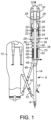
- FIG. 1 an FCC unit 6 is shown to which the process and apparatus of the present invention may be applied.
- the FCC unit 6 in Figure 1 represents only one of many FCC arrangements to which this invention can be applied.
- a regenerator standpipe 16 transfers catalyst from a regenerator 12 at a rate regulated by a slide valve 10.
- a fluidization medium from a nozzle 8 transports catalyst upwardly through a lower portion of a riser 14 at a relatively high density until a plurality of feed injection nozzles 18 (only one is shown) inject feed across the flowing stream of catalyst particles.
- the resulting mixture continues upward through an upper portion of the riser 14 until at least two disengaging arms 20 tangentially discharge the mixture of gas and catalyst through openings 22 from a top of the riser 14 into a disengaging vessel 24 that effects separation of gases from the catalyst.
- Most of the catalyst discharged from openings 22 falls downwardly in the disengaging vessel 24 into a bed 44.
- a transport conduit 26 carries the separated hydrocarbon vapors with entrained catalyst to one or more cyclones 28 in a reactor or separator vessel 30.
- the cyclones 28 separate spent catalyst from the hydrocarbon vapor stream.
- a collection chamber 31 gathers the separated hydrocarbon vapor streams from the cyclones for passage to an outlet nozzle 32 and into a downstream fractionation zone (not shown).
- Diplegs 34 discharge catalyst from the cyclones 28 into a bed 29 in a lower portion of the disengaging vessel 24 which pass through ports 36 into the bed 44 in the disengaging vessel 24.
- Catalyst and adsorbed or entrained hydrocarbons pass from the disengaging vessel 24 into a stripping vessel 38 across ports 36.
- Catalyst from openings 22 separated in the disengaging vessel 24 passes directly into the stripping vessel 38.
- the inlets to the stripping vessel 38 include openings 22 and ports 36.
- the stripping vessel 38 includes a first stripping section 60 and a second stripping section 62.
- the first stripping section 60 includes at least one grid 64 having at least one opening to allow catalyst to pass there through.
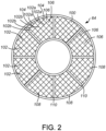
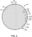
- the grids 64, 164 comprise grating 100, 200 or a series of elongate strips 102, 202 with a first plurality of the strips 102a, 202a running in a first direction and a second plurality of the strips 102b, 202b running in a second direction perpendicular to the first direction. Between the intersections 104, 204 of the various strips 102a, 102b, 202a, 202b are a plurality of openings 106, 206.
- both the first stripping section 60 and the second stripping section 62 may be disposed in an annulus 70 between the riser 14 and a shell 66 of the stripping vessel 38.
- the grid(s) 64 in the first stripping section 60 may comprise a plurality of generally sector shaped sections 108 as shown in Figure 2 .
- the sector shaped sections 108 are spaced apart from each other by a gap 110.
- Other configurations are also contemplated.
- the grids 164 may comprise a grating 200 that extends over the almost all of or the entire horizontal cross section of the stripping vessel 38.
- the grating 100 may also comprise sections that are separated by a gap.
- other preferred grids are disclosed in U.S. Pat. Nos. 6,680,030 and 7,077,997 .
- each ribbon 42a, 42b comprises bands 54 configured in undulating peaks 82 and valleys 84.
- Each band 54 includes a face 56 that obstructs passage of fluid and catalyst.
- the bands 54 include laterals 55 arranged to provide peaks 82 at an upper landing 63 and valleys 84 at a lower landing 65, but the peaks 82 and valleys 84 may be provided at the apex of a joint of just two bands 54.
- Each layers A, B includes paired ribbons 42a, 42b.
- the lower landings 65 in upper ribbon 42a meet the upper landings 63 of the lower ribbon 42b.
- a stabilizing strip 74 may be disposed between the upper landing 63 and the lower landing 65. If the paired ribbons 42a, 42b are cut out of a common piece of metal, a stabilizing strip 74 may be obviated.
- the ribbon 42a is disposed at a phase that is 90° out of phase to the phase of the paired ribbon 42b. Other phase relationships may be used.
- the axial spacing of a ribbon 42a is offset from the axial spacing of its paired ribbon 42b. Consequently, the edges 58 of the ribbon 42a and the edges 58 of the ribbon 42b may be parallel and may define a plane there between.
- the edges 58 of the laterals 55 and the landings 63, 65 in ribbon 42a and the edges 58 of the laterals 55 and the landings 63, 65 in ribbon 42b define openings 80 for the horizontal passage of the rising stripping fluid and the falling catalyst particles.
- the edges of laterals 55 and landings 63, 65 in alternating upper ribbons 42a and alternating lower ribbons 42b define openings 61 for the vertical passage of the rising stripping fluid and the falling catalyst particles.
- openings 80, 61 are also defined by the faces 56 of the laterals 55 and the upper and the lower landings 63, 65.
- Dimples 76 may be provided in the bands 54. Although shown in the laterals 55 near the valleys 84, the dimples 76 may be disposed in the lower landings 65. It is also contemplated that the edges 58 of the laterals 55 may be secured to each other in which case the laterals 55 would cross each other.
- the ribbons 42a, 42b are preferably stacked horizontally in the second stripping section 62, the ribbons 42a, 42b may be arranged vertically in the second stripping section 62. Other configurations for the structured packing 50 in the second stripping section 62 may be used. For example, although not depicted as such the ribbons in the second stripping section 62 may include segments with upper and lower tabs extending away therefrom in alternative directions. Such ribbons are disclosed for example in U.S. Pat. No. 7,332,132 .
- first stripping section 60 and the at least one grid 64 is disposed above the second stripping section 62 and the structured packing 50, it is contemplated (although not shown) that the second stripping section 62 is disposed above the first stripping section 60, and that the structured packing 50 is above the grid(s) 64.
- stripping gas such as steam enters a lower portion of the stripping vessel 38 through a distributor 40 and rises counter-current to a downward flow of catalyst through the second section 62 of the stripping vessel 38, and then the first section 60 of the stripping vessel 38, thereby removing adsorbed and entrained hydrocarbons from the catalyst.
- the hydrocarbons flow upwardly through and are ultimately recovered with the steam by the cyclones 28.
- the distributor 40 distributes the stripping gas around the circumference of the stripping vessel 38.
- the stripping gas removes the entrained hydrocarbons from the spent catalyst, and rises up through the stripping vessel 38.
- the spent catalyst leaves the stripping vessel 38 through a port 48 of a conduit 46 and passes into the regenerator 12.
- the catalyst is regenerated in the regenerator 12 as is known in the art and sent back to the riser 14 through the regenerator standpipe 16.
- the at least one grid 64 is preferably spaced between 0.91 m (3 ft.) to 1.5 m (5 ft.) from the second stripping section 62. If the first stripping section 60 includes a plurality of grids 64, the grids 64 are preferably each spaced apart from each other between 0.91 m (3 ft.) to 1.5 m (5 ft.). In some embodiments, the spacing between the grid 64 and the second stripping section is at least 0.91 m (3 ft.) and possibly greater than 1.5 m (5 ft.).
- the grid(s) 64 in the first stripping section 60 are most preferably spaced from the second stripping section 62 so as to minimize an accumulation of catalyst on top of the second stripping section 62, which is in some embodiments at least 1.2 m (4 ft.), or at least 0.91 m (3 ft.) or 0.61 m (2 ft.).
- the number of grids 64 in the first stripping section 60 will be dependent on the spacing between the top of the second stripping section 62 and the inlets into the stripping vessel 38.
- the use of the grids 64 in the first stripping section 60 allows for existing stripping vessels 38 to be retrofitted with more efficient stripping equipment while minimizing catalyst mal-distribution that may occur as a result of excess space above the stripping equipment in the stripping vessel 38.
- the grids 64 provide a cost efficient solution without negatively impacting the flow of the catalyst, stripping vapors, or recovered hydrocarbons.
Landscapes
- Chemical & Material Sciences (AREA)
- Engineering & Computer Science (AREA)
- Organic Chemistry (AREA)
- Chemical Kinetics & Catalysis (AREA)
- Materials Engineering (AREA)
- Combustion & Propulsion (AREA)
- Production Of Liquid Hydrocarbon Mixture For Refining Petroleum (AREA)
Claims (10)
- Cuve de stripage (38) pour éliminer les hydrocarbures d'un catalyseur, la cuve de stripage (38) comprenant :une entrée (22, 36) configurée pour recevoir un flux de particules de catalyseur usé, au moins certaines des particules de catalyseur usé comprenant des hydrocarbures entraînés ;une première section de stripage (60), la première section de stripage (60) incluant au moins une grille (64), chaque grille (64) comprenant un grillage (100), chaque grille (64) incluant au moins une ouverture (106, 206) pour permettre le passage du catalyseur ;une seconde section de stripage (62), la seconde section de stripage (62) incluant un garnissage structuré (50) composé d'une pluralité de rubans (42a, 42b), chaque ruban (42a, 42b) comprenant des bandes (54) configurées en pics (82) et creux (84) ondulants, chaque bande (54) inclut une face (56) qui obstrue le passage de fluide et de catalyseur, la au moins une grille (64) dans la première section de stripage (60) étant espacée du garnissage structuré (50) de la seconde section de stripage (62) ; etune sortie (48) configurée pour faire passer des particules de catalyseur depuis la cuve de stripage (38).
- Cuve de stripage (38) selon la revendication 1, comprenant en outre :
au moins une entrée (40) pour un fluide de stripage. - Cuve de stripage (38) selon la revendication 2, dans laquelle l'entrée (40) pour fluide de stripage est disposée en dessous de la seconde section de stripage (62).
- Cuve de stripage (38) selon la revendication 1, comprenant en outre :
une colonne montante interne (14). - Cuve de stripage (38) selon la revendication 1, dans laquelle la au moins une grille (64) dans la première section de stripage (60) inclut une pluralité d'ouvertures (106, 206) pour permettre le passage du catalyseur.
- Cuve de stripage (38) selon l'une quelconque des revendications 1 à 5, dans laquelle un espacement entre la au moins une grille (64) dans la première section de stripage (60) et le garnissage structuré (50) dans la seconde section de stripage (62) est entre 0,91 m (3 ft.) et 1,5 m (5 ft.).
- Cuve de stripage (38) selon la revendication 6, comprenant en outre :une seconde grille (64) dans la première section de stripage (60), la seconde grille (64) étant disposée au-dessus de la première grille (64),dans laquelle un espacement entre la au moins une grille (64) et la seconde grille (64) dans la première section de stripage (60) est entre 0,91 m (3 ft) et 1,5 m (5 ft).
- Cuve de stripage selon l'une quelconque des revendications 1 à 5, dans laquelle un nombre de grilles (64) dans la première section de stripage (60) dépend d'une distance entre un sommet de la première section de stripage (60) et un sommet de la seconde section de stripage (62), de telle sorte que les grilles (64) dans la première section de stripage (60) sont espacées d'au moins 0,91 m (3 ft) et d'au plus 1,5 m (5 ft).
- Procédé de stripage d'hydrocarbures d'un catalyseur comprenant :le passage d'un flux de particules de catalyseur vers une cuve de stripage (38), dans lequel au moins certaines des particules de catalyseur comprennent des hydrocarbures entraînés ;le passage de particules de catalyseur à travers une première section de stripage (60) de la cuve de stripage (38), la première section de stripage (60) incluant au moins une grille (64) ;le passage de particules de catalyseur à travers une seconde section de stripage (62) de la cuve de stripage (38), la seconde section de stripage (62) comprenant un garnissage structuré (52) composé d'une pluralité de rubans (42a, 42b), chaque ruban (42a, 42b) comprenant des bandes (54) configurées en pics (82) et creux (84) ondulants, chaque bande (54) inclut une face (56) qui obstrue le passage de fluide et de catalyseur ; etle stripage d'hydrocarbures des particules de catalyseur dans au moins l'une de la première section de stripage (60) et de la seconde section de stripage (62) avec un fluide de stripage,dans lequel la au moins une grille (64) dans la première section comprend une pluralité d'ouvertures (106, 206) pour permettre au catalyseur de passer à travers la au moins une grille (64), et chaque grille (64) comprenant un grillage (100) ;et dans lequel la au moins une grille dans la première section de stripage (60) est espacée du garnissage structuré de la seconde section de stripage (62).
- Procédé selon la revendication 9, dans lequel la au moins une grille (64) dans la première section de stripage (60) est espacée du garnissage structuré (52) dans la seconde section de stripage (62) d'une distance d'au moins 0,91 m (3 ft.).
Applications Claiming Priority (2)
| Application Number | Priority Date | Filing Date | Title |
|---|---|---|---|
| US14/561,781 US9446398B2 (en) | 2014-12-05 | 2014-12-05 | Stripping vessel for removing hydrocarbons entrained in catalyst particles |
| PCT/US2015/062992 WO2016089768A1 (fr) | 2014-12-05 | 2015-11-30 | Cuve de décapage pour éliminer les hydrocarbures entraînés dans des particules de catalyseur |
Publications (3)
| Publication Number | Publication Date |
|---|---|
| EP3227409A1 EP3227409A1 (fr) | 2017-10-11 |
| EP3227409A4 EP3227409A4 (fr) | 2018-07-04 |
| EP3227409B1 true EP3227409B1 (fr) | 2024-01-10 |
Family
ID=56092293
Family Applications (1)
| Application Number | Title | Priority Date | Filing Date |
|---|---|---|---|
| EP15866041.5A Active EP3227409B1 (fr) | 2014-12-05 | 2015-11-30 | Cuve de décapage pour éliminer les hydrocarbures entraînés dans des particules de catalyseur |
Country Status (3)
| Country | Link |
|---|---|
| US (1) | US9446398B2 (fr) |
| EP (1) | EP3227409B1 (fr) |
| WO (1) | WO2016089768A1 (fr) |
Families Citing this family (4)
| Publication number | Priority date | Publication date | Assignee | Title |
|---|---|---|---|---|
| US9707533B2 (en) | 2015-12-01 | 2017-07-18 | Dow Global Technologies Llc | Fluidized catalyst stripping unit for displacing entrained gas from catalyst particles |
| US10118144B2 (en) * | 2017-03-31 | 2018-11-06 | Uop Llc | Vessel for removing hydrocarbons on catalyst |
| US11167258B2 (en) | 2019-05-14 | 2021-11-09 | Uop Llc | Apparatus and process for separating gases from catalyst and revamp |
| FR3117895B1 (fr) * | 2020-12-23 | 2024-03-01 | Total Raffinage Chimie | Enceinte de separation et de stripage avec une grille de filtration de debris |
Family Cites Families (9)
| Publication number | Priority date | Publication date | Assignee | Title |
|---|---|---|---|---|
| US2472502A (en) * | 1945-07-28 | 1949-06-07 | Standard Oil Dev Co | Apparatus for stripping finely dividfd solids |
| US4364905A (en) | 1979-11-23 | 1982-12-21 | Standard Oil Company (Indiana) | Fluid catalytic cracking apparatus having riser reactor and improved means associated with the riser reactor for separating cracked product and entrained particulate catalyst |
| US4481103A (en) | 1983-10-19 | 1984-11-06 | Mobil Oil Corporation | Fluidized catalytic cracking process with long residence time steam stripper |
| FR2728805B1 (fr) | 1994-12-29 | 1997-03-28 | Total Raffinage Distribution | Procede et dispositif pour le strippage de solides fluidises et utilisation dans un procede de craquage a l'etat fluide |
| US6224833B1 (en) | 1998-12-15 | 2001-05-01 | Koch-Glitsch, Inc. | Apparatus for contacting of gases and solids in fluidized beds |
| US6740227B2 (en) | 1999-12-29 | 2004-05-25 | Uop Llc | Stripping process with fully distributed openings on baffles |
| US6680030B2 (en) | 1999-12-29 | 2004-01-20 | Uop Llc | Stripping process with horizontal baffles |
| US7077997B1 (en) * | 2002-08-16 | 2006-07-18 | Uop Llc | Stripping apparatus |
| US7332132B2 (en) * | 2004-03-19 | 2008-02-19 | Uop Llc | Stripping apparatus and process |
-
2014
- 2014-12-05 US US14/561,781 patent/US9446398B2/en active Active
-
2015
- 2015-11-30 WO PCT/US2015/062992 patent/WO2016089768A1/fr active Application Filing
- 2015-11-30 EP EP15866041.5A patent/EP3227409B1/fr active Active
Also Published As
| Publication number | Publication date |
|---|---|
| US9446398B2 (en) | 2016-09-20 |
| US20160158741A1 (en) | 2016-06-09 |
| EP3227409A1 (fr) | 2017-10-11 |
| EP3227409A4 (fr) | 2018-07-04 |
| WO2016089768A1 (fr) | 2016-06-09 |
Similar Documents
| Publication | Publication Date | Title |
|---|---|---|
| EP1577368B1 (fr) | Appareil et procédé de strippage | |
| JP5388583B2 (ja) | 剥離装置及び方法 | |
| US6680030B2 (en) | Stripping process with horizontal baffles | |
| EP3227409B1 (fr) | Cuve de décapage pour éliminer les hydrocarbures entraînés dans des particules de catalyseur | |
| EP2798042B1 (fr) | Appareils d'extraction des hydrocarbures gazeux à partir de particules et procédés associés | |
| US11261143B2 (en) | Apparatus and process for separating gases from catalyst | |
| AU777989B2 (en) | Stripping process with fully distributed openings on baffles | |
| US7077997B1 (en) | Stripping apparatus | |
| US7022221B1 (en) | Stripping apparatus and process | |
| US7972565B2 (en) | Stripping apparatus with multi-sloped baffles | |
| US8877133B2 (en) | Apparatuses for stripping gaseous hydrocarbons from particulate material and processes for the same | |
| EP3601484B1 (fr) | Récipient servant à éliminer des hydrocarbures d'un catalyseur | |
| US10974238B2 (en) | Process for combustion coke from coked catalyst | |
| WO2020232050A1 (fr) | Appareil et procédé pour la séparation de gaz à partir d'un catalyseur | |
| WO2010036499A2 (fr) | Procede et appareil de stripage à deflecteurs à pentes multiples |
Legal Events
| Date | Code | Title | Description |
|---|---|---|---|
| STAA | Information on the status of an ep patent application or granted ep patent |
Free format text: STATUS: THE INTERNATIONAL PUBLICATION HAS BEEN MADE |
|
| PUAI | Public reference made under article 153(3) epc to a published international application that has entered the european phase |
Free format text: ORIGINAL CODE: 0009012 |
|
| STAA | Information on the status of an ep patent application or granted ep patent |
Free format text: STATUS: REQUEST FOR EXAMINATION WAS MADE |
|
| 17P | Request for examination filed |
Effective date: 20170524 |
|
| AK | Designated contracting states |
Kind code of ref document: A1 Designated state(s): AL AT BE BG CH CY CZ DE DK EE ES FI FR GB GR HR HU IE IS IT LI LT LU LV MC MK MT NL NO PL PT RO RS SE SI SK SM TR |
|
| AX | Request for extension of the european patent |
Extension state: BA ME |
|
| DAV | Request for validation of the european patent (deleted) | ||
| DAX | Request for extension of the european patent (deleted) | ||
| A4 | Supplementary search report drawn up and despatched |
Effective date: 20180606 |
|
| RIC1 | Information provided on ipc code assigned before grant |
Ipc: B01J 8/34 20060101ALN20180531BHEP Ipc: B01J 38/06 20060101ALN20180531BHEP Ipc: B01J 19/32 20060101ALI20180531BHEP Ipc: B01D 45/00 20060101ALI20180531BHEP Ipc: B01J 8/18 20060101ALI20180531BHEP Ipc: B01J 8/26 20060101ALN20180531BHEP Ipc: C10G 11/18 20060101AFI20180531BHEP Ipc: B01J 29/90 20060101ALN20180531BHEP |
|
| STAA | Information on the status of an ep patent application or granted ep patent |
Free format text: STATUS: EXAMINATION IS IN PROGRESS |
|
| 17Q | First examination report despatched |
Effective date: 20220816 |
|
| P01 | Opt-out of the competence of the unified patent court (upc) registered |
Effective date: 20230421 |
|
| GRAP | Despatch of communication of intention to grant a patent |
Free format text: ORIGINAL CODE: EPIDOSNIGR1 |
|
| STAA | Information on the status of an ep patent application or granted ep patent |
Free format text: STATUS: GRANT OF PATENT IS INTENDED |
|
| RIC1 | Information provided on ipc code assigned before grant |
Ipc: B01J 29/90 20060101ALN20230731BHEP Ipc: B01J 38/06 20060101ALN20230731BHEP Ipc: B01J 8/26 20060101ALN20230731BHEP Ipc: B01J 8/34 20060101ALN20230731BHEP Ipc: B01D 45/00 20060101ALI20230731BHEP Ipc: B01J 8/18 20060101ALI20230731BHEP Ipc: B01J 19/32 20060101ALI20230731BHEP Ipc: C10G 11/18 20060101AFI20230731BHEP |
|
| INTG | Intention to grant announced |
Effective date: 20230823 |
|
| GRAS | Grant fee paid |
Free format text: ORIGINAL CODE: EPIDOSNIGR3 |
|
| GRAA | (expected) grant |
Free format text: ORIGINAL CODE: 0009210 |
|
| STAA | Information on the status of an ep patent application or granted ep patent |
Free format text: STATUS: THE PATENT HAS BEEN GRANTED |
|
| AK | Designated contracting states |
Kind code of ref document: B1 Designated state(s): AL AT BE BG CH CY CZ DE DK EE ES FI FR GB GR HR HU IE IS IT LI LT LU LV MC MK MT NL NO PL PT RO RS SE SI SK SM TR |
|
| REG | Reference to a national code |
Ref country code: GB Ref legal event code: FG4D |
|
| REG | Reference to a national code |
Ref country code: CH Ref legal event code: EP |
|
| REG | Reference to a national code |
Ref country code: DE Ref legal event code: R096 Ref document number: 602015087259 Country of ref document: DE |
|
| REG | Reference to a national code |
Ref country code: IE Ref legal event code: FG4D |
|
| REG | Reference to a national code |
Ref country code: LT Ref legal event code: MG9D |
|
| REG | Reference to a national code |
Ref country code: NL Ref legal event code: MP Effective date: 20240110 |
|
| REG | Reference to a national code |
Ref country code: AT Ref legal event code: MK05 Ref document number: 1648894 Country of ref document: AT Kind code of ref document: T Effective date: 20240110 |
|
| PG25 | Lapsed in a contracting state [announced via postgrant information from national office to epo] |
Ref country code: NL Free format text: LAPSE BECAUSE OF FAILURE TO SUBMIT A TRANSLATION OF THE DESCRIPTION OR TO PAY THE FEE WITHIN THE PRESCRIBED TIME-LIMIT Effective date: 20240110 |
|
| PG25 | Lapsed in a contracting state [announced via postgrant information from national office to epo] |
Ref country code: NL Free format text: LAPSE BECAUSE OF FAILURE TO SUBMIT A TRANSLATION OF THE DESCRIPTION OR TO PAY THE FEE WITHIN THE PRESCRIBED TIME-LIMIT Effective date: 20240110 |
|
| PG25 | Lapsed in a contracting state [announced via postgrant information from national office to epo] |
Ref country code: IS Free format text: LAPSE BECAUSE OF FAILURE TO SUBMIT A TRANSLATION OF THE DESCRIPTION OR TO PAY THE FEE WITHIN THE PRESCRIBED TIME-LIMIT Effective date: 20240510 |
|
| PG25 | Lapsed in a contracting state [announced via postgrant information from national office to epo] |
Ref country code: LT Free format text: LAPSE BECAUSE OF FAILURE TO SUBMIT A TRANSLATION OF THE DESCRIPTION OR TO PAY THE FEE WITHIN THE PRESCRIBED TIME-LIMIT Effective date: 20240110 |
|
| PG25 | Lapsed in a contracting state [announced via postgrant information from national office to epo] |
Ref country code: GR Free format text: LAPSE BECAUSE OF FAILURE TO SUBMIT A TRANSLATION OF THE DESCRIPTION OR TO PAY THE FEE WITHIN THE PRESCRIBED TIME-LIMIT Effective date: 20240411 |
|
| PG25 | Lapsed in a contracting state [announced via postgrant information from national office to epo] |
Ref country code: HR Free format text: LAPSE BECAUSE OF FAILURE TO SUBMIT A TRANSLATION OF THE DESCRIPTION OR TO PAY THE FEE WITHIN THE PRESCRIBED TIME-LIMIT Effective date: 20240110 Ref country code: RS Free format text: LAPSE BECAUSE OF FAILURE TO SUBMIT A TRANSLATION OF THE DESCRIPTION OR TO PAY THE FEE WITHIN THE PRESCRIBED TIME-LIMIT Effective date: 20240410 |
|
| PG25 | Lapsed in a contracting state [announced via postgrant information from national office to epo] |
Ref country code: ES Free format text: LAPSE BECAUSE OF FAILURE TO SUBMIT A TRANSLATION OF THE DESCRIPTION OR TO PAY THE FEE WITHIN THE PRESCRIBED TIME-LIMIT Effective date: 20240110 |
|
| PG25 | Lapsed in a contracting state [announced via postgrant information from national office to epo] |
Ref country code: AT Free format text: LAPSE BECAUSE OF FAILURE TO SUBMIT A TRANSLATION OF THE DESCRIPTION OR TO PAY THE FEE WITHIN THE PRESCRIBED TIME-LIMIT Effective date: 20240110 |
|
| PG25 | Lapsed in a contracting state [announced via postgrant information from national office to epo] |
Ref country code: RS Free format text: LAPSE BECAUSE OF FAILURE TO SUBMIT A TRANSLATION OF THE DESCRIPTION OR TO PAY THE FEE WITHIN THE PRESCRIBED TIME-LIMIT Effective date: 20240410 Ref country code: NO Free format text: LAPSE BECAUSE OF FAILURE TO SUBMIT A TRANSLATION OF THE DESCRIPTION OR TO PAY THE FEE WITHIN THE PRESCRIBED TIME-LIMIT Effective date: 20240410 Ref country code: LT Free format text: LAPSE BECAUSE OF FAILURE TO SUBMIT A TRANSLATION OF THE DESCRIPTION OR TO PAY THE FEE WITHIN THE PRESCRIBED TIME-LIMIT Effective date: 20240110 Ref country code: IS Free format text: LAPSE BECAUSE OF FAILURE TO SUBMIT A TRANSLATION OF THE DESCRIPTION OR TO PAY THE FEE WITHIN THE PRESCRIBED TIME-LIMIT Effective date: 20240510 Ref country code: HR Free format text: LAPSE BECAUSE OF FAILURE TO SUBMIT A TRANSLATION OF THE DESCRIPTION OR TO PAY THE FEE WITHIN THE PRESCRIBED TIME-LIMIT Effective date: 20240110 Ref country code: GR Free format text: LAPSE BECAUSE OF FAILURE TO SUBMIT A TRANSLATION OF THE DESCRIPTION OR TO PAY THE FEE WITHIN THE PRESCRIBED TIME-LIMIT Effective date: 20240411 Ref country code: ES Free format text: LAPSE BECAUSE OF FAILURE TO SUBMIT A TRANSLATION OF THE DESCRIPTION OR TO PAY THE FEE WITHIN THE PRESCRIBED TIME-LIMIT Effective date: 20240110 Ref country code: BG Free format text: LAPSE BECAUSE OF FAILURE TO SUBMIT A TRANSLATION OF THE DESCRIPTION OR TO PAY THE FEE WITHIN THE PRESCRIBED TIME-LIMIT Effective date: 20240110 Ref country code: AT Free format text: LAPSE BECAUSE OF FAILURE TO SUBMIT A TRANSLATION OF THE DESCRIPTION OR TO PAY THE FEE WITHIN THE PRESCRIBED TIME-LIMIT Effective date: 20240110 |
|
| PG25 | Lapsed in a contracting state [announced via postgrant information from national office to epo] |
Ref country code: PT Free format text: LAPSE BECAUSE OF FAILURE TO SUBMIT A TRANSLATION OF THE DESCRIPTION OR TO PAY THE FEE WITHIN THE PRESCRIBED TIME-LIMIT Effective date: 20240510 Ref country code: PL Free format text: LAPSE BECAUSE OF FAILURE TO SUBMIT A TRANSLATION OF THE DESCRIPTION OR TO PAY THE FEE WITHIN THE PRESCRIBED TIME-LIMIT Effective date: 20240110 |
|
| PG25 | Lapsed in a contracting state [announced via postgrant information from national office to epo] |
Ref country code: SE Free format text: LAPSE BECAUSE OF FAILURE TO SUBMIT A TRANSLATION OF THE DESCRIPTION OR TO PAY THE FEE WITHIN THE PRESCRIBED TIME-LIMIT Effective date: 20240110 Ref country code: PT Free format text: LAPSE BECAUSE OF FAILURE TO SUBMIT A TRANSLATION OF THE DESCRIPTION OR TO PAY THE FEE WITHIN THE PRESCRIBED TIME-LIMIT Effective date: 20240510 Ref country code: PL Free format text: LAPSE BECAUSE OF FAILURE TO SUBMIT A TRANSLATION OF THE DESCRIPTION OR TO PAY THE FEE WITHIN THE PRESCRIBED TIME-LIMIT Effective date: 20240110 Ref country code: LV Free format text: LAPSE BECAUSE OF FAILURE TO SUBMIT A TRANSLATION OF THE DESCRIPTION OR TO PAY THE FEE WITHIN THE PRESCRIBED TIME-LIMIT Effective date: 20240110 |