EP3226525B1 - Control system, communication terminal, control device, communication system, control method, and program - Google Patents
Control system, communication terminal, control device, communication system, control method, and program Download PDFInfo
- Publication number
- EP3226525B1 EP3226525B1 EP15863118.4A EP15863118A EP3226525B1 EP 3226525 B1 EP3226525 B1 EP 3226525B1 EP 15863118 A EP15863118 A EP 15863118A EP 3226525 B1 EP3226525 B1 EP 3226525B1
- Authority
- EP
- European Patent Office
- Prior art keywords
- terminal
- information
- communication terminal
- control device
- communication
- Prior art date
- Legal status (The legal status is an assumption and is not a legal conclusion. Google has not performed a legal analysis and makes no representation as to the accuracy of the status listed.)
- Active
Links
- 238000004891 communication Methods 0.000 title claims description 214
- 238000000034 method Methods 0.000 title claims description 20
- 230000004044 response Effects 0.000 claims description 49
- 238000013475 authorization Methods 0.000 claims description 38
- 238000012217 deletion Methods 0.000 claims description 3
- 230000037430 deletion Effects 0.000 claims description 3
- 238000004590 computer program Methods 0.000 claims 1
- 238000010586 diagram Methods 0.000 description 43
- 230000005540 biological transmission Effects 0.000 description 25
- 230000001360 synchronised effect Effects 0.000 description 20
- 239000000470 constituent Substances 0.000 description 15
- 230000007704 transition Effects 0.000 description 14
- 230000006870 function Effects 0.000 description 7
- 230000000694 effects Effects 0.000 description 4
- 238000009434 installation Methods 0.000 description 4
- 238000012545 processing Methods 0.000 description 4
- 230000005236 sound signal Effects 0.000 description 4
- 238000003384 imaging method Methods 0.000 description 3
- 230000001413 cellular effect Effects 0.000 description 2
- 230000002452 interceptive effect Effects 0.000 description 2
- 241001522296 Erithacus rubecula Species 0.000 description 1
- 230000000295 complement effect Effects 0.000 description 1
- 238000001816 cooling Methods 0.000 description 1
- 238000005401 electroluminescence Methods 0.000 description 1
- 239000000284 extract Substances 0.000 description 1
- 239000004973 liquid crystal related substance Substances 0.000 description 1
- 229910044991 metal oxide Inorganic materials 0.000 description 1
- 150000004706 metal oxides Chemical class 0.000 description 1
- 238000003825 pressing Methods 0.000 description 1
- 239000004065 semiconductor Substances 0.000 description 1
- 238000004904 shortening Methods 0.000 description 1
- 239000007787 solid Substances 0.000 description 1
Images


Classifications
-
- H—ELECTRICITY
- H04—ELECTRIC COMMUNICATION TECHNIQUE
- H04M—TELEPHONIC COMMUNICATION
- H04M3/00—Automatic or semi-automatic exchanges
- H04M3/42—Systems providing special services or facilities to subscribers
- H04M3/56—Arrangements for connecting several subscribers to a common circuit, i.e. affording conference facilities
- H04M3/562—Arrangements for connecting several subscribers to a common circuit, i.e. affording conference facilities where the conference facilities are distributed
-
- H—ELECTRICITY
- H04—ELECTRIC COMMUNICATION TECHNIQUE
- H04L—TRANSMISSION OF DIGITAL INFORMATION, e.g. TELEGRAPHIC COMMUNICATION
- H04L65/00—Network arrangements, protocols or services for supporting real-time applications in data packet communication
- H04L65/40—Support for services or applications
- H04L65/403—Arrangements for multi-party communication, e.g. for conferences
-
- H—ELECTRICITY
- H04—ELECTRIC COMMUNICATION TECHNIQUE
- H04L—TRANSMISSION OF DIGITAL INFORMATION, e.g. TELEGRAPHIC COMMUNICATION
- H04L67/00—Network arrangements or protocols for supporting network services or applications
- H04L67/14—Session management
- H04L67/141—Setup of application sessions
-
- H—ELECTRICITY
- H04—ELECTRIC COMMUNICATION TECHNIQUE
- H04N—PICTORIAL COMMUNICATION, e.g. TELEVISION
- H04N7/00—Television systems
- H04N7/14—Systems for two-way working
- H04N7/15—Conference systems
-
- H—ELECTRICITY
- H04—ELECTRIC COMMUNICATION TECHNIQUE
- H04M—TELEPHONIC COMMUNICATION
- H04M3/00—Automatic or semi-automatic exchanges
- H04M3/42—Systems providing special services or facilities to subscribers
- H04M3/56—Arrangements for connecting several subscribers to a common circuit, i.e. affording conference facilities
- H04M3/567—Multimedia conference systems
Definitions
- the present invention relates to a control system, a communication terminal, a control device, a communication system, a control method, and a program.
- a teleconference management system that manages the teleconference (see Patent Literature 1).
- the teleconference management system is connected to the teleconference terminals, and performs control for establishing a session based on the information received from the teleconference terminals.
- a plurality of teleconference management systems is installed, and the information such as a start request mentioned above is sent to the teleconference terminals via the plurality of teleconference management systems.
- This teleconference system allows the teleconference management systems representing the connection destinations of the teleconference terminals to be distributed. That enables achieving reduction in load for establishing a session in each teleconference management system.
- WO 2013/172482 A1 discloses a transmission / reception unit of a management system which receives a relay device ID transmitted by a selection device. Also, the transmission / reception unit transmits communication control request information to another management system based on the relay device ID. Consequently, a relay device to be used to relay content data to be transmitted / received among terminals can be selected from relay devices that the other management system can control.
- a control system includes a plurality of control devices that control a session for sending contents data among communication terminals.
- Each of the plurality of control devices includes a destination information sending unit configured to send destination information indicating address of a first communication terminal connected to concerned control device in a communication network to a management device that manages the destination information; a destination information receiving unit configured to receive sets of destination information each of which indicates address of a second communication terminal connected to another control device from among the plurality of control devices and each of which is sent by the management device; an inter-terminal information receiving unit configured to receive, from among inter-terminal information sent between the first communication terminal and the second communication terminal, the inter-terminal information sent by the first communication terminal; and an inter-terminal information sending unit configured to send, based on the destination information of the second communication terminal received by the destination information receiving unit, the inter-terminal information received by the inter-terminal information receiving unit to the second communication terminal.
- FIG. 1 is a schematic view illustrating the state of transmission and reception of a variety of information in a communication system 1.
- a communication terminal is simply referred to as a "terminal”.
- the communication system is built using a plurality of terminals 10aa, 10bb, and 10cc, a plurality of relay devices 30xx, 30yy, and 30zz, and a management system 5.
- the management system 5 includes a plurality of control devices 50x, 50y, and 50z and a common management device 60.
- an arbitrary terminal is referred to as the "terminal 10”.
- an arbitrary relay device is referred to as the "relay device 30”.
- an arbitrary control device is referred to as the "control device 50".
- Each terminal 10 performs communication by sending and receiving contents data. Moreover, one or more relay devices 30 relay contents data among a plurality of terminals 10. As a result, among a plurality of terminals 10, one or more sessions get established for sending one or more sets of contents data.
- a session for sending one or more sets of contents data is referred to as a session sed.
- contents data gets exchanged among the terminals 10, thereby making it possible to perform communication such as telephone calls among a plurality of business establishments, telephone calls among different rooms of the same business establishment, telephone calls within the same room, or telephone calls between an outdoor place and an indoor place or between outdoor places. Meanwhile, when the terminals 10 are used outdoors, wireless communication using a cellular phone communication network can be performed.
- the communication system 1 functions as a communication system that establishes a session sed via a communication management system (equivalent to a "management system") and enables mutual transmission of information and sentiments among a plurality of communication terminals (equivalent to "terminals").
- the explanation is given about a communication system, a management system, and a terminal under the assumption that a videoconference system represents an example of a communication system, a videoconference management system represents an example of a communication management system, and a videoconference terminal represents an example of a communication terminal. That is, the terminal and the communication system according to the present invention are not only applicable in a videoconference system but are also applicable in a communication system.
- the communication system 1 can be a telephone system
- the terminal 10 can be an IP (Internet Protocol) telephone, an Internet phone, or a PC (personal computer).
- videoconference is used in an interchangeable manner with the term “teleconference”.
- the communication system 1 can be implemented also in a case in which an application actively accesses a server at a center, and sends and obtains a variety of data. In that case, the other side of communication may not be a terminal and may be a server too.
- a terminal may be a gaming console or a car navigation device.
- the communication system 1 can be an information sharing system, and the terminal 10 can be a projector, a digital signage, or an interactive whiteboard.
- one or more sets of contents data sent among the terminals 10 include, for example, four sets of data, namely, high-resolution image data, medium-resolution image data, low-resolution image data, and audio data.
- images represented by image data either can be moving images or still images or can be moving images and still images.
- the low-resolution image data is, for example, 160 pixels wide and 120 pixels tall, and represents a base image.
- the medium-resolution image data is 320 pixels wide and 240 pixels tall.
- the high-resolution image data is, for example, 640 pixels wide and 480 pixels tall.
- image data of low image quality which is only low-resolution image data representing the base image
- image data of medium image quality which is low-resolution image data representing the base image and medium-resolution image data
- image data of high image quality which is low-resolution image data representing the base image, medium-resolution image data, and high-resolution image data
- the audio data has a smaller volume of data as compared to image data. Hence, the audio data gets relayed in a narrow-band channel too.
- a plurality of relay devices 30 constitute a relay system 3.
- Fig. 1 is illustrated the embodiment in which three relay devices 30 relay contents data among three terminals 10.
- the present invention is not limited to that case.
- the common management device 60 manages common information that represents a variety of information related to the terminals 10 or related to the sessions sed among the terminals 10, and that is used by each control device 50.
- a session for sending a variety of information is established via the control devices 50.
- a session sei such a session is referred to as a session sei.
- the variety of information sent among the terminals 10 contains a start request for starting communication, authorization for starting communication, and an end request for ending communication. Based on the variety of information sent from the terminals 10, each control device 50 can get to know the state of the terminals 10.
- Fig. 2 is a state transition diagram illustrating an example of state transitions of the terminal 10.
- state information such as "None” indicating a state of the terminal 10.
- the concerned terminal 10 issues a start request for starting communication with another terminal 10
- the state of communication of the terminal that issued the start request switches to the state of requesting for the start of communication with the other terminal 10 (the state indicated by state information "Inviting")
- the state of communication of the destination terminal 10 switches to the state of being requested for the start of communication from another terminal 10 (the state indicated by state information "Invited”).
- the destination terminal 10 outputs a ring alert
- the state of communication of the destination terminal 10 switches to the state of outputting a ring alert (the state indicated by state information "Ringing")
- the state of communication of the terminal 10 that issued the start request switches to the state of outputting a dial tone (the state indicated by state information "Calling").
- the terminal 10 that issued the start request and the destination terminal 10 switch to the state in which the start request is authorized (the state indicated by state information "Accepted”). Meanwhile, when a particular terminal 10 issues a start request for starting the relay of contents data, the state of communication of the terminal 10 switches to the state of performing communication (the state indicated by state information "Busy"). When a particular terminal 10 issues an end request for ending the communication, the state of communication of the terminal 10 that issued the end request returns to the state indicated by the state information "None". Moreover, when a particular terminal 10 issues a participation request for participating in an already-established session sed, the state of communication of the terminal 10 that issued the participation request switches to the state indicated by the state information "Accepted".
- the rules of state transition are only exemplary, and it is possible to adopt other rules in the communication system 1.
- a storage unit 5000 of each control device 50 is used to store information that indicates the rules of state transition illustrated in the state transition diagram in Fig. 2 .
- the control device 50 sends the start request to the destination terminal 10.
- the control device 50 can deny the start request and accurately perform call control between the terminals 10.
- each control device 50 manages, for example, the operating status (presence) of each terminal 10 with the aim of notifying the operating status to the users of the terminals 10.
- Examples of the operating status of a particular terminal 10 include: the state “Online” in which the terminal 10 is connected to the control device 50 but is not performing communication with other terminals 10; the state "Online (in a call)" in which the terminal 10 is connected to the control device 50 and is performing communication with other terminals 10; and the state “Offline” in which the terminal 10 is not connected to the control device 50.
- Each control device 50 notifies the terminal 10 connected thereto about the operating statuses of the terminals 10 representing the destination candidates of the concerned terminal 10.
- a corresponding display controller 17 updates, based on the operating statuses, the icons (see Fig. 3 ) representing the operating statuses in a destination list (see Fig. 3 ).
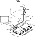
- Fig. 4 is an exemplary external view of the terminal 10 according to the embodiment.
- the terminal 10 includes a housing 1100, an arm 1200, and a camera housing 1300.
- an air intake face having a plurality of air intake holes is formed on a front wall surface 1110 of the housing 1100.
- a sound pickup hole 1131 is formed that enables a built-in microphone 114 (described later) to pick up any sound such as a voice, a noise, or a disturbing noise.
- an operation panel 1150 On the side of the right-side wall surface 1130 of the housing 1100, an operation panel 1150 is formed.
- the operation panel 1150 has a plurality of operation buttons (108a to 108e) (described later), a power switch 109 (described later), and an alarm lamp 119 (described later) installed thereon; as well as has an audio output face 1151 formed thereon with a plurality of audio output holes for letting out the output sound from a built-in speaker 115 (described later).
- a container 1160 in the form of a depression is formed for accommodating the arm 1200 and the camera housing 1300.
- a plurality of connecting ports (1132a to 1132c) is provided for electrically connecting cables to an external device connection I/F 118 (described later).
- a connecting port is provided for electrically connecting a cable 120c of a display 120 to the external device connection I/F 118 (described later).
- an arbitrary operation button is referred to as the "operation button 108”.
- an arbitrary connecting port is referred to as the "connecting port 1132”.
- the arm 1200 is attached to the housing 1100 via a torque hinge 1210, and is configured to be vertically rotatable with respect to the housing 1100 within the range of a tilt angle ⁇ 1 of 135°.
- Fig. 4 is illustrated the state in which the tilt angle ⁇ 1 is of 90°.
- the camera housing 1300 is installed a built-in camera 112 (described later) that can take images of users, documents, and rooms.
- a torque hinge 1310 is provided via which the camera housing 1300 is attached to the arm 1200 in a vertically-and-horizontally rotatable manner within a pan angle ⁇ 2 of ⁇ 180° and within a tilt angle ⁇ 3 of ⁇ 45° with the state illustrated in Fig. 4 representing 0°.
- the external view illustrated in Fig. 4 is only exemplary, and the terminal 10 is not limited to have that external view.
- Examples of the terminal 10 include a PC, a smartphone, and a tablet terminal.
- the camera and the microphone need not always be of the built-in type, and can be of the external type.
- the relay device 30, a relay management device 40, the control device 50, and the common management device 60 have the same external appearance as a commonly-used server computer. Hence, the explanation about that external appearance is not given.
- Fig. 5 is a hardware configuration diagram of the terminal 10 according to the present embodiment.
- the terminal 10 includes a CPU (Central Processing Unit) 101 that controls the overall operations of the terminal 10; a ROM (Read Only Memory) 102 that is used to store programs such as an IPL (Initial Program Loader) used in driving the CPU 101; a RAM (Random Access Memory) 103 that is used as the work area of the CPU 101; a flash memory 104 that is used to store a variety of data such as various terminal-intended programs, image data, and audio data; an SSD (Solid State Drive) 105 that controls reading or writing of a variety of data with respect to the flash memory 104 under the control of the CPU 101; a medium I/F 107 that controls reading or writing (storing) of data in a recording medium 106 such as a flash memory or an IC card (Integrated Circuit Card); the operation button 108 that is operated in the case of selecting a destination; the power switch 109 for switching ON and
- a CPU Central Processing Unit
- the terminal 10 includes the built-in camera 112 that takes images of photographic subjects under the control of the CPU 101 and obtains image data; an imaging element I/F 113 that controls the driving of the camera 112; the built-in microphone 114 that inputs audio; the built-in speaker 115 that outputs audio; an audio input-output I/F 116 for performing input and output of audio signals between the microphone 114 and the speaker 115 under the control of the CPU 101; a display I/F 117 for sending image data to the external display 120 under the control of the CPU 101; the external device connection I/F 118 for establishing connection with various external devices; the alarm lamp 119 that notifies malfunctioning of various functions of the terminal 10; and a bus line 110 such as an address bus or a data bus that electrically connects the abovementioned constituent elements in a manner illustrated in Fig. 5 .
- a bus line 110 such as an address bus or a data bus that electrically connects the abovementioned constituent elements in a manner illustrated in Fig. 5 .
- the display 120 is a display unit of liquid crystals or organic EL (Organic Electroluminescence) that displays images of photographic subjects and operation information.
- the display 120 is connected to the display I/F 117 via the cable 120c.
- the cable 120c can be a cable meant for analog RGB (VGA) signals, or can be a cable meant for component video signals, or can be a cable meant for HDMI (registered trademark) (High-Definition Multimedia Interface) signals or DVI (Digital Video Interactive) signals.
- the camera 112 includes a lens, and a solid-state image sensing device that converts light into electrical charge and computerizes the image (video) of a photographic subject.
- a solid-state image sensing device that converts light into electrical charge and computerizes the image (video) of a photographic subject.
- Examples of the solid-state image sensing device include a CMOS (Complementary Metal Oxide Semiconductor) and a CCD (Charge Coupled Device).
- external devices such as an external camera, an external microphone, and an external speaker can be electrically connected using USB (Universal Serial Bus) cables inserted in the connecting ports 1132 of the housing 1100.
- USB Universal Serial Bus
- an external camera When an external camera is connected, it is driven with priority over the built-in camera 112 under the control of the CPU 101.
- an external microphone When an external microphone is connected or an external speaker is connected, it is driven with priority over the built-in microphone 114 or the built-in speaker 115 under the control of the CPU 101.
- the recording medium 106 is configured to be detachably attachable to the terminal 10.
- the memory is not limited to the flash memory 104 and alternatively an EEPROM (Electrically Erasable and Programmable ROM) can also be used.
- Fig. 6 is a hardware configuration diagram of the control device 50.
- the control device 50 includes a CPU 501 that controls the overall operations of the control device 50; a ROM 502 that is used to store programs such as an IPL (Initial Program Loader) used in driving the CPU 501; a RAM 503 that is used as the work area of the CPU 501; an HD 504 that is used to store a variety of data such as programs meant for the control device 50; an HDD (Hard Disk Drive) 505 that controls reading or writing of a variety of data with respect to the HD 504 under the control of the CPU 501; a medium drive 507 that controls reading or writing (storing) of data in a recording medium 506 such as a flash memory; a display 508 that displays a variety of information such as a cursor, menus, windows, characters, and images; a network I/F 509 for performing data communication using the communication network 2; a keyboard 511 having a plurality of keys for inputting characters, numerical values, and various instructions
- the relay device 30 has an identical configuration to that of the control device 50. Hence, that explanation is not repeated.
- the programs meant for the terminal 10, the relay device 30, the control device 50, and the common management device 60 can be recorded as installable or executable files in a computer-readable recording medium, and can be distributed.
- the recording medium include a CD-R (Compact Disc Recordable), a DVD (Digital Versatile Disk), and a Blu-ray disc.
- the recording medium such as a CD-ROM in which the programs are stored and the HD 504 in which the programs are stored can be provided as a program product within and outside the country.
- control device 50 as well as the common management device 60 either can be configured using a single computer or can be configured using a plurality of computers among which the constituent elements (the functions or the modules) are divided and assigned in an arbitrary manner.
- the common management device 60 can be configured in any one of a plurality of control devices 50.
- Fig. 7 is an overall configuration according to the embodiment.
- Fig. 7 is an overall configuration diagram of the communication system according to the embodiment of the present invention.
- the terminals 10, the relay devices 30, the control devices 50, and the common management device 60 are communicably connected to other terminals and devices via the communication network 2.
- the communication network 2 can be a LAN2x (Local Area Network), the Internet, a cellular phone network, or a dedicated line.
- the connection among the relay devices 30, or the connection among the control devices 50, or the connection of the control devices 50 with the common management device 60 can be done using the communication network 2 as a dedicated line. That enables achieving stability in the communication among the devices.
- the communication performed via the communication network 2 can include wired communication and wireless communication.
- the relay devices (30xx and 30xy) and the control device 50x are installed in an area X.
- the area X represents Japan
- the relay devices (30xx and 30xy) and the control device 50x are installed in a data center in Tokyo.
- the relay devices (30yy and 30yz) and the control device 50y are installed in an area Y.
- the area Y represents the USA
- the relay devices (30yy and 30yz) and the control device 50y are installed in a data center in New York.
- the relay devices (30zz and 30zx) and the control device 50z are installed in an area Z.
- the area Z represents the Southeast Asia
- the relay devices (30zz and 30zx) and the control device 50z are installed in a data center in Singapore.
- the terminals 10aa, 10bb, and 10cc are portable in nature, and can be connected to the communication network 2 from the areas (X, Y, and Z) or can be connected to the communication network 2 from some other areas.
- the common management device 60 can be installed in one of the areas (X, Y, and Z), or can be installed in some other area.
- the relay device 30 and the control device 50 can be installed also in areas other than the areas (X, Y, and Z).
- FIG. 5 is a functional configuration according to the embodiment.
- Fig. 8 are illustrated functional block diagrams of the communication system according to the embodiment.
- the terminal 10 includes a transceiver 11, a receiver 12, a communication controller 13, the display controller 17, and a storing/reading unit 19.
- Each of those constituent elements is a function or a functioning module that is implemented when one of the constituent elements illustrated in Fig. 5 performs operations by following the instructions from the CPU 101 according to the terminal-intended program, which is loaded in the RAM 103 from the flash memory 104.
- the terminal 10 includes the RAM 103 and includes a storage unit 1000 configured using the flash memory 104.
- a recording medium 1010 configured using the recording medium 106 is inserted and is subjected to reading and writing of a variety of data by the storing/reading unit 19.
- the transceiver 11 is implemented by the network I/F 111 in response to an instruction from the CPU 101, and performs transmission and reception of a variety of data (or information) with other terminals, devices, or systems via the communication network 2.
- the communication controller 13 is implemented by the camera 112 and the imaging element I/F 113 in response to an instruction from the CPU 101, and takes an image of the photographic subject and outputs image data obtained by imaging. Moreover, the communication controller 13 is implemented by the audio input-output I/F 116 in response to an instruction from the CPU 101; and, after the voice of the user is converted into audio signals by the microphone 114, receives input of audio data related to the audio signals. Furthermore, the communication controller 13 is implemented by the audio input-output I/F 116 in response to an instruction from the CPU 101, and outputs the audio signals related to the audio data to the speaker and causes the speaker 115 to output the voice.
- the display controller 17 is implemented by the display I/F 117 in response to an instruction from the CPU 101; and combines the received sets of image data having different resolutions and performs control to send the combined image data to the display 120.
- the display controller 17 can send information, which is received from the control device 50, to the display 120 and causes the display 120 to display the display.
- the storing/reading unit 19 is either implemented using the SSD 105 in response to an instruction from the CPU 101 or implemented in response to an instruction from the CPU 101, and performs operations of storing a variety of data in the storage unit 1000 or the recording medium 1010 and reading a variety of data from the storage unit 1000 or the recording medium 1010.
- the storage unit 1000 is used to store a terminal ID (Identification), which enables identification of the terminal 10, and a password. Meanwhile, at least either the terminal ID or the password can be recorded in the recording medium 1010 and can be read by the storing/reading unit 19.
- the recording medium 1010 is an IC card (Integrated Circuit card) such as a SIM card (Subscriber Identity Module Card).
- SIM card Subscriber Identity Module Card
- the received data is stored in the storage unit 1000 in an overwriting manner.
- an image is displayed on the display 120 using the pre-overwriting image data, and a voice is output from the speaker 115 using the pre-overwriting audio data.
- the terminal ID according to the present embodiment is an example of identification information in the form of a word, or a character, or a symbol, or various signs.
- the identification information can be a combination of at least two items from among a word, a character, a symbol, and various signs.
- the terminal ID it is alternatively possible to use a user ID that enables identification of the user of the terminal 10. In that case, the terminal identification information contains not only the terminal ID but also the user ID.
- the control device 50 includes a transceiver 51, an authenticating unit 52, a manager 53, a searching unit 54, a session controller 58, and a storing/reading unit 59.
- Each of those constituent elements is a function or a functioning module that is implemented when one of the constituent elements illustrated in Fig. 6 performs operations by following the instructions from the CPU 501 according to the program that is meant for the control device 50 and that is loaded in the RAM 503 from the HD 504.
- the control device 50 includes the storage unit 5000 that is configured using the HD 504.
- the storage unit 5000 of the control device 50 is used to store area IDs of the areas (X, Y, and Z) in which the concerned control device 50 and the other control devices 50 are installed.
- area ID "jp01" is stored that indicates Japan as the location of installation of the control device 50x
- area ID "us01” is stored that indicates the USA as the location of installation of the control device 50y
- area ID "sg01” is stored that indicates Singapore as the location of installation of the control device 50z.
- an authentication management DB 5001 that is built using an authentication management table
- a terminal management DB 5002 that is built using a terminal management table
- a destination list management DB 5003 that is built using a destination list management table
- a session management DB 5004 that is built using a session management table
- a relay device management DB 5011 that is built using a relay device management table
- an operating status management DB 5012 that is built using an operating status management table
- a connection management DB 5013 that is built using a connection management table.
- FIG. 9 (A) is a conceptual diagram illustrating the authentication management table.
- terminal IDs enabling identification of the terminals 10; passwords; and service IDs of the services available in the terminals 10 are managed in a corresponding manner.
- the terminals 10aa, 10bb, and 10cc have terminal IDs "01aa@xx.com, 01bb@xx.com, and 01cc@xx.com, respectively.
- the portion "@xx.com" included in the terminal IDs can be omitted because it is common among the terminals 10.
- (B) is a conceptual diagram illustrating the terminal management table.
- the terminal management table with respect to the terminal ID of each terminal 10, the following information is managed in a corresponding manner: a destination name (for example, a terminal name); state information indicating the state of the concerned terminal 10; an IP address indicating the address of the concerned terminal 10; an area ID of the control device 50 to which the concerned terminal 10 is connected; and a relay device ID of the relay device 30 to which the concerned terminal 10 is connected.
- (D) is a conceptual diagram illustrating the session management table.
- the terminal IDs of the terminals 10 that are participating in that session sed are managed in a corresponding manner.
- one of the relay devices 30 manages the entire relay of contents data and, with that relay device 30 representing the starting point, information indicating the relay destinations of contents data is provided to the other relay devices 30.
- the session ID contains domain information (for example "001xx") indicating the relay device (for example, the relay device 30xx) that represents the starting point in the session sed.
- (E) is a conceptual diagram illustrating the relay device management table.
- the relay device management table with respect to a relay device ID of each relay device 30, the area ID of the area of installation of that relay device 30 and the URI (Uniform Resource Identifier) of that relay device 30 are managed in a corresponding manner.
- URI Uniform Resource Identifier
- FIG. 9 (F) is a conceptual diagram illustrating the operating status management table.
- the operating status management table with respect to the terminal ID of each terminal 10, the operating status (presence) of that terminal 10 is managed in a corresponding manner.
- (G) is a conceptual diagram illustrating the connection management table.
- the connection management table with respect to the terminal ID of each terminal 10, the following information is managed in a corresponding manner: a relay device connection ID that is generated every time when the terminal 10 establishes connection with a particular relay device 30; and a relay device connection password that is used in authenticating the terminal 10 when the terminal 10 establishes connection with that relay device 30.
- the transceiver 51 is implemented by the network I/F 509 in response to an instruction from the CPU 501, and performs transmission and reception of a variety of data (or information) with other terminals, devices, or systems via the communication network 2.
- the authenticating unit 52 is implemented in response to an instruction from the CPU 501; and searches the authentication management table (see Fig. 9(A) ) with the terminal ID and the password received by the transceiver 51 serving as the search keys, and authenticates the terminal 10 by determining whether or not the same terminal ID and the same password are managed in the authentication management table.
- the manager 53 is implemented in response to an instruction from the CPU 501, and manages all management tables by adding a variety of information to and deleting a variety of information from the management tables.
- the searching unit 54 is implemented in response to an instruction from the CPU 501, and performs a node search in order to search for the terminals 10 (nodes) connected to the other control devices 50.
- the session controller 58 is implemented in response to an instruction from the CPU 501, and controls a session sed in which contents data is sent among the terminals 10.
- the abovementioned control includes the control for establishing a session sed, the control for causing the terminals 10 to participate in the session sed, and the control for terminating the session sed.
- the storing/reading unit 59 is either implemented using the HDD 505 in response to an instruction from the CPU 501 or implemented in response to an instruction from the CPU 501, and performs operations of storing a variety of data in the storage unit 5000 and reading a variety of data from the storage unit 5000.
- the common management device 60 includes a transceiver 61 and a storing/reading unit 69. Each of those constituent elements is a function or a functioning module that is implemented when one of the constituent elements illustrated in Fig. 6 performs operations by following the instructions from the CPU 501 according to the program that is meant for the common management device and that is loaded in the RAM 503 from the HD 504. Moreover, the common management device 60 includes a storage unit 6000 that is configured using the HD 504.
- an authentication management DB 6001 that is built using an authentication management table
- a terminal management DB 6002 that is built using a terminal management table
- a destination list management DB 6003 that is built using a destination list management table
- a session management DB 6004 that is built using a session management table.
- the authentication management DB 6001, the terminal management DB 6002, the destination list management DB 6003, and the session management DB 6004 managed in the common management device are in synchronization with and are used to manage common information as the authentication management DB 5001, the terminal management DB 5002, the destination list management DB 5003, and the session management DB 5004, respectively, managed in the control device 50.
- the transceiver 61 is implemented by the network I/F 509 in response to an instruction from the CPU 501, and performs transmission and reception of a variety of data (or information) with other terminals, devices, or systems via the communication network 2.
- the storing/reading unit 69 is either implemented using the HDD 505 in response to an instruction from the CPU 501 or implemented in response to an instruction from the CPU 501, and performs operations of storing a variety of data in the storage unit 6000 and reading a variety of data from the storage unit 6000.
- the relay device 30 includes a transceiver 31, an authenticating unit 32, and a storing/reading unit 39. Each of those constituent elements is a function or a functioning module that is implemented when one of the constituent elements illustrated in Fig. 6 performs operations by following the instructions from the CPU 501 according to the program that is meant for the common management device and that is loaded in the RAM 503 from the HD 504. Moreover, the relay device 30 includes a storage unit 3000 that is configured using the HD 504.
- the transceiver 31 is implemented by the network I/F 509 in response to an instruction from the CPU 501, and performs transmission and reception of a variety of data (or information) with other terminals, devices, or systems via the communication network 2.
- the authenticating unit 32 is implemented in response to an instruction from the CPU 501, and authenticates the terminal 10 by determining whether or not the group including the terminal ID, the relay device connection ID, and the relay device connection password is managed in the connection management table in the control device 50 (see Fig. 9(G) ).
- the storing/reading unit 39 is either implemented using the HDD 505 in response to an instruction from the CPU 501 or implemented in response to an instruction from the CPU 501, and performs operations of storing a variety of data in the storage unit 3000 and reading a variety of data from the storage unit 3000.
- Fig. 10 is a sequence diagram illustrating a login operation performed by the terminal 10.
- the terminal 10 can log in to any arbitrary control device 50 from among a plurality of control devices 50.
- the method of selecting the control device 50 to which a particular terminal 10 issues a login request. Examples of that method include a method of selecting the control device 50 based on the information input in the concerned terminal 10; a method of selecting the closest control device 50 based on the physical position information of the concerned terminal 10; and a method of selecting the control device 50 using the GSLB (Global Server Load Balancing).
- GSLB Global Server Load Balancing
- the transceiver 11 of the concerned terminal 10 sends a login request and the IP address of the concerned terminal 10 to an arbitrary control device 50 that has been selected (Step S1).
- the login request includes the terminal ID and the password of the terminal 10 that issued the login request.
- the IP address thereof gets sent to the control device 50 to which the login request is issued.
- the transceiver 51 of the concerned control device 50 receives the login request, which includes the terminal ID and the password, and the IP address of the terminal 10.
- the authenticating unit 52 refers to the authentication management table ( Fig. 9(A) ) and authenticates the terminal 10 that issued the login request (Step S2).
- the authenticating unit 52 successfully authenticates the terminal 10 that issued the login request.
- the authenticating unit 52 fails in authenticating the terminal 10 that issued the login request. The following explanation is given for the case in which the authentication is successful.
- the storing/reading unit 59 searches the authentication management table with the terminal ID and the password of the terminal 10 that issued the login request serving as the search keys, and reads the corresponding service ID.
- the manager 53 assigns, to the terminal 10 that issued the login request, the area ID indicating the area in which the concerned control device 50 is installed (Step S3).
- the area ID is stored in advance in the storage unit 5000 of the control device 50. For example, if the control device 50 that receives the login request is installed in the area X (Japan), then the manager 53 assigns "jp01" as the area ID to the terminal 10 that issued the login request.
- the storing/reading unit 59 stores, in the operating status management table (see Fig. 9(F) ), the operating status "Online” in a corresponding manner to the terminal ID of the terminal 10 that issued the login request (Step S4).
- the manager 53 manages the state of communication of the terminal 10, which issued the login request, according to the rules of state transition illustrated in the state transition diagram illustrated in Fig. 2 (Step S5). That is, at Step S4, when the operating status is set to "Online", the manager 53 decides on "None” as the state information indicating the new state of the terminal 10 that issued the login request (See Fig. 2 ).
- the session controller 58 selects the relay device 30 representing the connection destination of the terminal 10 that issued the login request (Step S6).
- the session controller 58 selects, from the session management table, the relay device 30 that is identified by the relay device ID managed in a corresponding manner to the area ID (for example, "jp01") of the area (for example, the area X) in which the concerned control device 50 is installed, that is, the relay device 30 that is installed in the same area as the concerned control device 50.
- the storing/reading unit 59 searches the relay device management table (see Fig. 9(E) ) with the relay device ID of the selected relay device 30 serving as the search key, and reads the corresponding URI.
- the session controller 58 of the control device 50 generates a relay device connection ID that is used at the time when the terminal 10 that issued the login request establishes connection with the relay device 30 selected at Step S5 (Step S7).
- the storing/reading unit 59 stores, in the connection management table (see Fig. 9(G) ), the generated relay device connection ID and a relay device connection password in a corresponding manner to the terminal ID of the terminal 10 that issued the login request.
- the relay device connection password either can be determined in advance for each relay device 30, or can be generated every time a particular terminal 10 establishes connection with a particular relay device 30.
- the transceiver 51 of the control device 50 issues an updating request for updating the terminal management table to the common management device 60 (Step S8-1).
- the updating request includes the terminal ID and IP address of the terminal 10 that issued the login request; the area ID assigned at Step S3; the state information determined at Step S5; and the relay device ID of the relay device 30 selected at Step S6.
- the storing/reading unit 69 stores, in the terminal management table (see Fig. 9(B) ) managed in the common management device 60, the following information in a corresponding manner: the terminal ID, the IP address, the state information, the area ID, and the relay device ID included in the updating request.
- the transceiver 61 of the common management device 60 sends, to the control devices 50x, 50y, and 50z constituting the communication system 1, the updated contents of the terminal management table including the terminal ID, the state information, the area ID, and the relay device ID.
- the transceiver 51 of each of the control devices 50x, 50y, and 50z receives the updated contents
- the storing/reading unit 59 of each control device 50 updates the terminal management table, which is managed in that control device 50, based on the received updated contents.
- the terminal management table in each of the control devices 50x, 50y, and 50z gets synchronized with the terminal management table managed in the common management device 60 (Steps S8-2-1, S8-2-).
- the transceiver 51 of the control device 50 sends, to the terminal 10 that issued the login request, the authentication result indicating that the authentication was successful; the URI of the relay device 30 as read at Step S6; and the relay device connection ID and the relay device connection password as generated at Step S7 (Step S9).
- the transceiver 11 of the terminal 10 Upon receiving the URI, the relay device connection ID, and the relay device connection password from the control device 50; the transceiver 11 of the terminal 10 issues a login request to the relay device 30 specified by the URI (Step S10).
- the login request includes the terminal ID of the terminal 10 that issued the login request, and includes the relay device connection ID and the relay device connection password received from the control device 50.
- the authenticating unit 32 authenticates the terminal 10 that issued the login request (Step S11).
- the authenticating unit 32 inquires, with the control device 50 installed in the same area as the concerned relay device, whether or not the group of the terminal ID, the relay device connection ID, and the relay device connection password included in the login request is also managed in the connection management table in the control device 50 (see Fig. 9(G) ).
- the manager 53 refers to the connection management table and sends the result about the inquiry to the relay device 30 using the transceiver 51.
- the authenticating unit 32 successfully authenticates the terminal 10 that issued the login request. However, if the group of the terminal ID, the relay device connection ID, and the relay device connection password included in the login request is not managed in the connection management table in the control device 50, then the authenticating unit 32 fails in authenticating the terminal 10 that issued the login request.
- the transceiver 31 of the relay device 30 sends the authentication result to the terminal 10 that issued the login request (Step S12).
- Fig. 11 is a sequence diagram for explaining the operations performed to display a destination list in the terminal.
- the corresponding transceiver 11 issues, to the control device 50 via the transceiver 11, a destination list request that includes the terminal ID of the concerned terminal 10 and that represents a request for a destination list (Step S21).
- the transceiver 51 of the control device 50 receives the destination list request.
- the storing/reading unit 59 searches the destination list management table (see Fig. 9(C) ) with the terminal ID of the terminal 10 that issued the destination list request serving as the search key, and extracts the terminal IDs of destination candidate terminals 10 which are specifiable as the destination by the terminal 10 that issued the destination list request (Step S22). Moreover, the storing/reading unit 59 searches the terminal management table (see Fig. 9(B) ) with the extracted terminal IDs serving as the search keys, and reads the destination names. Then, the transceiver 51 of the control device 50 sends the terminal IDs of the destination candidate terminals 10 and the destination names, which are read by the storing/reading unit 59, to the terminal 10 that issued the destination list request (Step S23).
- the corresponding display controller 17 displays, on the display 120, a destination list, in which specifiable destination candidate names are reflected, based on the terminal IDs and the destination names included in the destination list information (see Fig. 3 ) (Step S24).
- the terminal 10 issues a destination-list-management-table updating request, which includes the terminal ID of the destination candidate terminal 10 to be added or deleted and the terminal ID of the concerned terminal, to the control device 50 (Step S25).
- the control device 50 that receives the updating request, in response to a request from the manager 53, the transceiver 51 sends the destination-list-management-table updating request to the common management device 60 (Step S26-1).
- This updating request includes the terminal ID of the terminal 10 that issued the updating request and the terminal ID of the destination candidate terminal 10 to be added or deleted.
- the storing/reading unit 69 of the common management device 60 adds, in the destination list management table, the terminal ID of the to-be-added destination candidate, which is included in the updating request, as the terminal ID of a destination candidate associated with the terminal ID of the terminal 10 that issued the updating request.
- the storing/reading unit 69 of the common management device 60 deletes, from the destination list management table, the terminal ID of the to-be-deleted destination candidate, which is included in the updating request, from among the terminal IDs of the destination candidates associated with the terminal ID of the terminal 10 that issued the updating request.
- the transceiver 61 of the common management device 60 sends, to the control devices 50x, 50y, and 50z constituting the communication system 1, the updated contents of the destination list management table.
- the transceiver 51 of each of the control devices 50x, 50y, and 50z receives the updated contents
- the storing/reading unit 59 of each control device 50 updates the destination list management table, which is managed in that control device 50, based on the received updated contents.
- the destination list management table in each of the control devices 50x, 50y, and 50z gets synchronized with the destination list management table managed in the common management device 60 (Steps S26-2-1, S26-2-).
- Fig. 12 is a sequence diagram for explaining the operations of synchronizing the operating statuses among the control devices.
- the searching unit 54 of the control device 50x performs a node search to search for the destination candidate terminals 10 (herein, assumed to be the terminals 10bb and 10cc (Steps S41-1 and S41-2).
- the node search is performed in order to get to know the control devices 50 to which the destination candidate terminals 10, which are not connected to the concerned control device 50, are connected.
- the node search is performed with respect to such terminals from among the destination candidate terminals 10 which are not connected to the concerned control device 50.
- the corresponding transceiver 51 in response to a request from the searching unit 54 of the control device 50x, the corresponding transceiver 51 sends search information regarding a node search to the other control devices 50y and 50z.
- the search information contains the terminal ID of the terminal 10aa that is connected to the control device 50x, and contains the terminal IDs of the destination candidate terminals 10bb and 10cc that are not connected to the control device 50x.
- the corresponding session controller 58 determines whether or not the terminals 10bb and 10cc, which are identified by the terminal IDs included in the search information, are connected to the control device 50x (Steps S42-1 and S42-2).
- the method for determining the connection with a particular terminal 10 there is no particular restriction and any known method can be implemented. Examples of the method include a method in which, in a session sei, the determination is performed based on whether or not a period of time exceeding a predetermined threshold value has elapsed since the last time of reception of information that is periodically sent by the terminal 10.
- the session controller 58 determines that the terminal 10bb or the terminal 10cc that is identified by a terminal ID is not connected to the concerned control device 50 (No at Steps S42-1 and S42-2), then that control device 50 ends the operations without sending a response to the control device 50 which sent the search information.
- the following explanation is given for the case in which the session controller 58 determines that the terminal 10bb or the terminal 10cc that is identified by a terminal ID is connected to the concerned control device 50 (Yes at Steps S42-1 and S42-2).
- the storing/reading unit 59 of each of the control devices 50y and 50z reads, from the operating status management table (see Fig. 9(F) ), the operating status corresponding to the terminal ID of the terminal 10 of the terminal 10bb or the terminal 10cc that is connected to the concerned control device 50 from among the destination candidate terminals 10 specified in the search information (Steps S43-1 and S43-2).
- the transceiver 51 of each of the control devices 50y and 50z sends, to the control device 50x, a notification about the terminal ID of the terminal 10bb or the terminal 10cc that is connected to the concerned control device 50 and about the operating status read at Step S43-1 or Step S43-2 (Steps S44-1 and S44-2).
- the transceiver 51 of the control device 50x receives each notification
- the corresponding searching unit 54 identifies the control device 50 that sent the notification as the connection destination of the terminal 10bb or the terminal 10cc identified by the terminal ID specified in the notification.
- the transceiver 11 sends the received notifications to the terminal 10aa that has performed login (Steps S45-1 and S45-2).
- the display controller 17 updates, based on the terminal IDs and the operating statuses of the destination candidate terminals 10bb and 10cc specified in the notifications, the icons representing the operating statuses of the destination candidate terminals 10bb and 10cc in the destination list (see Fig. 3 ) (Steps S46-1 and S46-2).
- the storing/reading unit 59 stores, in the operating status management table managed in the concerned control device 50, the operating statuses, which are specified in the notifications received from the control devices 50y and 50z, in a corresponding manner to the terminal IDs of the terminals 10bb and 10cc specified in the notifications (Steps S47-1 and S47-2).
- the control device 50x becomes able to know the operating statuses of the destination candidate terminals 10bb and 10cc of the terminal 10aa that is connected to the control device 50x.
- the storing/reading unit 59 of the control device 50x reads, from the operating status management table, the operating status corresponding to the terminal ID of the terminal 10aa that is connected to the control device 50x (Step S48). Then, the transceiver 51 of the control device 50x sends, to the control devices 50y and 50z representing the connection destinations of the destination candidate terminals 10bb and 10cc, respectively, the terminal ID of the terminal 10aa and the operating status read at Step S48 (Step S49-1 and S49-2). Upon receiving the notification, the transceiver 51 of each of the control devices 50y and 50z sends the received notification to the terminal 10bb or the terminal 10cc connected to the concerned control device 50 (Steps S50-1 and S50-2).
- the corresponding display controller 17 updates, based on the terminal ID and the operating status of the terminal 10aa as specified in the notification, the icon representing the operating status of the terminal 10aa in the destination list (Steps S51-1 and S51-2).
- each of the control devices 50y and 50z in response to a request from the corresponding manager 53, the corresponding storing/reading unit 59 updates, in the operating status management table managed in the concerned control device 50, the operating status of the terminal 10aa based on the notification received from the control device 50x (Steps S52-1 and S52-2). As a result, each of the control devices 50y and 50z becomes able to know the operating status of the terminal 10aa that is connected to the control device 50x.
- the transceiver 11 of the terminal 10aa issues a start request for starting communication to the control device 50x (Step S61).
- the start request for starting communication includes the terminal ID "01aa” of the terminal 10aa that issued the start request for starting communication, and includes the terminal ID "01bb" of the destination terminal 10bb.
- the storing/reading unit 59 stores, in the operating status management table (see Fig. 9(F) ), the operating status "Online (in a call)" in a corresponding manner to the terminal ID of the terminal 10aa that issued the start request (Step S62).
- the updated operating status "Online (in a call)" is notified to the destination candidate terminals 10 of the terminal 10aa as a result of the operations performed from Step S48 to Steps S52-1 and S52-2.
- the manager 53 manages the state of communication of the terminal 10 according to the rules of state transition illustrated in the state transition diagram in Fig. 2 (Step S63-1). That is, at Step S61, in response to the start request received by the control device 50x, the manager 53 decides on "Inviting" as the state information indicating the new state of the terminal 10aa that issued the start request, and decides on "Invited” as the state information indicating the new state of the destination terminal 10bb.
- the manager 53 issues, to the common management device 60, an updating request that is meant for updating the terminal management table and that includes the state information "Inviting” and “Invited” indicating the new states of the terminal 10aa that issued the start request and the destination terminal 10bb, respectively, in a corresponding manner to the terminal IDs of the terminals 10aa and 10bb.
- the storing/reading unit 69 stores the terminal IDs and the sets of state information, which are included in the updating request, in a corresponding manner in the terminal management table (see Fig. 9(B) ) managed in the common management device 60. Then, as a result of performing the operations identical to Steps S8-2-1, S8-2-...; the terminal management table managed in each of the control devices 50x, 50y, and 50z gets synchronized with the terminal management table managed in the common management device 60 (Steps S63-2-1, S63-2-2, S63-2-).
- the session controller 58 selects, from among the relay devices 30xx and 30yy connected to the terminals 10aa and 10bb, respectively, the relay device 30 representing the starting point in the session sed (Step S64).
- the two relay devices 30xx and 30yy relay the contents data.
- the relay device 30 that is selected at Step S64 entirely manages the relay destinations (destinations) of in-session contents among the nodes (the terminals 10 and the relay devices 30). That is, with the selected relay device 30 representing the starting point, information indicating the relay destinations of contents data is provided to the other relay devices 30. Meanwhile, there is no restriction on the method for selecting the relay device 30 at Step S64.
- the explanation is given under the assumption that the relay device 30xx, to which the terminal 10 that issued the start request is connected, is selected.
- the manager 53 manages the information related to the session sed established between the terminals 10aa and 10bb (Step S65-1).
- the manager 53 generates a session ID for enabling identification of the session sed established between the terminals 10aa and 10bb.
- the manager 53 generates a session ID (for example, "conf01.001xx”) that includes the information (for example, "001xx”) indicating the relay device 30xx that represents the starting point selected at Step S64.
- the transceiver 61 of the common management device 60 issues, to the common management device 60, an updating request that is for updating the session management table (see Fig. 9(D) ) and that includes the generated session ID; the terminal ID of the terminal 10aa that issued the start request; and the terminal ID of the destination terminal 10bb.
- the storing/reading unit 69 stores, in the session management table managed in the common management device 60, the session ID and the terminal IDs included in the updating request. Then, the transceiver 61 sends the updated contents of the session management table to the control devices 50x, 50y, and 50z constituting the communication system 1.
- the transceiver 51 of each of the control devices 50x, 50y, and 50z receives the updated contents
- the corresponding storing/reading unit 59 updates, based on the updated contents, the session management table managed in the concerned control device 50.
- the terminal management table managed in each of the control devices 50x, 50y, and 50z gets synchronized with the session management table managed in the common management device 60 (Step S65-2-).
- the transceiver 51 of the control device 50x sends the session ID, which is generated at Step S65-1, to the terminal 10aa that issued the start request (Step S66). Furthermore, the transceiver 51 of the control device 50x sends the start request, which is received from the terminal 10aa that issued the start request, and the session ID to the destination terminal 10bb (Step S67). Meanwhile, based on the IP address of the terminal 10bb as received from the common management device 60, the terminal management table (see Fig. 9(B) ) managed in the control device 50x becomes synchronous with the terminal management table managed in the common management device 60 and is used in managing the IP address of the destination terminal 10bb.
- the transceiver 51 of the control device 50x can send the start request directly to the terminal 10bb without having to make any inquiry about the IP address to the control device 50y that is the connection destination of the destination terminal 10bb or without having to perform communication via the control device 50y.
- the corresponding communication controller 13 causes the speaker 115 to output an audible ringing tone. Then, the transceiver 11 of the terminal 10bb sends ringing information, which indicates that an audible ringing tone is output, to the control device 50y representing the connection destination of the terminal 10bb (Step S68).
- the ringing information contains the terminal ID of the terminal 10aa that issued the start request and the terminal ID of the destination terminal 10bb.
- the corresponding manager 53 manages the state of communication of the terminals 10 according to the rules of state transition illustrated in the state transition diagram in Fig. 2 (Step S69-1). That is, at Step S68, based on the ringing information received by the control device 50y, the manager 53 decides on "Calling" as the state information indicating the new state of the terminal 10aa that issued the start request and decides on "Ringing" as the state information indicating the new state of the destination terminal 10bb.
- the manager 53 issues, to the common management device 60, an updating request that is meant for updating the terminal management table and that includes the state information "Calling” and “Ringing” indicating the new states of the terminal 10aa that issued the start request and the destination terminal 10bb, respectively, in a corresponding manner to the terminal IDs of the terminals 10aa and 10bb.
- the storing/reading unit 69 stores the terminal IDs and the sets of state information, which are included in the updating request, in a corresponding manner in the terminal management table (see Fig. 9(B) ) managed in the common management device 60. Then, as a result of performing the operations identical to Steps S8-2-1, S8-2-...; the terminal management table managed in each of the control devices 50x, 50y, and 50z gets synchronized with the terminal management table managed in the common management device 60 (Steps S69-2-1, S69-2-2, S69-2-).
- the transceiver 51 of the control device 50y sends the ringing information, which is received from the destination terminal 10bb, to the terminal 10aa that issued the start request (Step S70). Meanwhile, since the terminal management table (see Fig. 9(B) ) managed in the control device 50y is synchronous with the terminal management table managed in the common management device 60 based on the information received from the common management device 60, the IP address of the terminal 10aa that issued the start request is managed in the terminal management table in the control device 50y.
- the transceiver 51 of the control device 50y can send the ringing information directly to the terminal 10aa without having to make any inquiry about the IP address to the control device 50x that is the connection destination of the destination terminal 10aa or without having to perform communication via the control device 50x.
- the transceiver 11 sends start authorization information, which indicates authorization for starting communication, to the control device 50y representing the connection destination of the terminal 10bb (Step S71).
- the start authorization information contains the terminal ID of the terminal 10aa that issued the start request and the terminal ID of the destination terminal 10bb.
- the corresponding manager 53 When the transceiver 51 of the control device 50y receives the start authorization information, the corresponding manager 53 performs an operation identical to Step S69 and, based on the start authorization information that is received, decides on "Accepted” as the state information indicating the new state of the terminal 10aa, which issued the start request, and the destination terminal 10bb. Then, the manager 53 issues, to the common management device 60, an updating request that is meant for updating the terminal management table and that includes the state information "Accepted” indicating the new state of the terminal 10aa, which issued the start request, and the destination terminal 10bb in a corresponding manner to the terminal IDs of the terminals 10aa and 10bb (Step S72-1).
- the storing/reading unit 69 stores the terminal IDs and the sets of state information, which are included in the updating request, in a corresponding manner in the terminal management table (see Fig. 9(B) ) managed in the common management device 60. Then, as a result of performing the operations identical to Steps S8-2-1, S8-2-...; the terminal management table managed in each of the control devices 50x, 50y, and 50z gets synchronized with the terminal management table managed in the common management device 60 (Steps S72-2-1, S72-2-2, S72-2-).
- the transceiver 51 of the control device 50y performs an operation identical to Step S70 and sends the start authorization information, which is received from the destination terminal 10bb, to the terminal 10aa that issued the start request (Step S73).
- FIG. 14 each figure is a sequence diagram for explaining the operations for starting the relay of contents data.
- Step S73 the transceiver 11 of the terminal 10aa, which issued the start request, sends relay request information, which indicates a request to start the relay of contents data, to the control device 50x (Step S81).
- the relay request information contains the terminal ID of the terminal 10aa that issued the relay request and the session ID "conf01.001 xx" received at Step S66.
- the corresponding manager 53 When the transceiver 51 of the control device 50x receives the relay request information, the corresponding manager 53 performs an operation identical to Step S63-1 and, based on the relay request information that is received, decides on "Busy" as the state information indicating the new state of the terminal 10aa that issued the relay request. Then, the manager 53 issues, to the common management device 60, an updating request that is meant for updating the terminal management table and that includes the terminal ID of the terminal 10aa, which issued the relay request, and the state information "Busy" indicating the new state of the terminal 10aa (Step S82-1).
- the storing/reading unit 69 stores the terminal ID and the state information, which are included in the updating request, in a corresponding manner in the terminal management table (see Fig. 9(B) ) managed in the common management device 60. Then, as a result of performing the operations identical to Steps S8-2-1, S8-2-...; the terminal management table managed in each of the control devices 50x, 50y, and 50z gets synchronized with the terminal management table managed in the common management device 60 (Steps S82-2-1, S82-2-).
- the transceiver 51 of the control device 50x sends the relay request information, which is received from the terminal 10aa that issued the relay request, to the relay device 30xx identified by the relay device ID "001xx" (Step S83).
- the transceiver 31 of the relay device 30xx sends relay authorization information, which indicates authorization for the relay, to the control device 50x (Step S84).
- the transceiver 51 of the control device 50x Upon receiving the relay authorization information sent by the relay device 30xx, the transceiver 51 of the control device 50x sends the relay authorization information to the terminal 10aa that issued the relay request (Step S85).
- the relay device 30xx when the transceiver 31 of the relay device 30xx receives the relay request information, the relay device 30xx becomes able to know that the terminal 10aa, which issued the relay request, is participating in the session identified by the session ID included in the relay request information. As a result, the relay device 30xx starts relaying the contents data that is received from the terminal 10aa to the other terminals 10 participating in the same session as the session in which the terminal 10aa is participating, as well as starts sending the contents data that is received from the other terminals 10 to the terminal 10aa. In this way, the session sed between the terminal 10aa and the relay device 30xx gets established.
- Step S71 the transceiver 11 of the terminal 10bb sends relay request information, which indicates a request to start the relay of contents data, to the control device 50y (Step S91).
- the relay request information contains the terminal ID of the terminal 10bb that issued the relay request and the session ID "conf01.001xx" received at Step S67.
- the corresponding manager 53 When the transceiver 51 of the control device 50y receives the relay request information, the corresponding manager 53 performs an operation identical to Step S69-1 and, based on the relay request information that is received, decides on "Busy" as the state information indicating the new state of the terminal 10bb that issued the relay request. Then, the manager 53 issues, to the common management device 60, an updating request that is meant for updating the terminal management table and that includes the terminal ID of the terminal 10bb, which issued the relay request, and the state information "Busy" indicating the new state of the terminal 10bb (Step S92-1).
- the storing/reading unit 69 stores the terminal ID and the state information, which are included in the updating request, in a corresponding manner in the terminal management table (see Fig. 9(B) ) managed in the common management device 60. Then, as a result of performing the operations identical to Steps S8-2-1, S8-2-..., the terminal management table managed in each of the control devices 50x, 50y, and 50z gets synchronized with the terminal management table managed in the common management device 60 (Steps S92-2-1, S92-2-).
- the transceiver 51 of the control device 50y sends the relay request information, which is received from the terminal 10bb that issued the relay request, to the relay device 30yy identified by the relay device ID "001yy” (Step S93).
- the relay device 30yy Since the session ID "conf01.001xx" that is specified in the relay request information includes the information "001xx" indicating the relay device 30xx that represents the starting point, the relay device 30yy that receives the relay request information becomes able to know that the relay device 30xx is the starting relay device 30 in the session sed. Thus, the transceiver 31 of the relay device 30yy sends the relay request information, which is received from the control device 50y, to the relay device 30xx representing the starting point (Step S94).
- the transceiver 31 of the relay device 30xx sends relay authorization information, which indicates authorization for the relay, to the relay device 30yy (Step S95). Then, in response to the relay request information, the transceiver 31 of the relay device 30yy sends relay authorization information, which indicates authorization for the relay, to the control device 50y (Step S96). Upon receiving the relay authorization information sent by the relay device 30yy, the transceiver 51 of the control device 50y sends the relay authorization information to the terminal 10bb that issued the relay request (Step S97).
- the relay device 30xx When the transceiver 31 of the relay device 30xx receives the relay request information, the relay device 30xx becomes able to know that the terminal 10bb, which is connected to the relay device 30yy, is participating in the session that is identified by the session ID specified in the relay request information. Thus, based on the relay devices 30 to which the terminals 10 participating in the session sed are connected, the relay device 30xx determines the transmission path for sending contents data and notifies the relay device 30yy about the transmission path. For example, the relay device 30xx issues, to the relay device 30yy, a request for sending the contents data received from the terminal 10bb to the relay device 30xx and for sending the contents data received from the relay device 30xx to the terminal 10bb.
- the relay device 30yy starts sending the contents data received from the terminal 10bb to the relay device 30xx, as well as starts sending the contents data of the terminal 10aa as received from the relay device 30xx to the terminal 10bb.
- the session sed gets established between the terminal 10bb and the relay device 30yy and between the relay devices 30xx and 30yy.
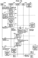
- Fig. 15 is a sequence diagram for explaining the operations by which the terminal 10 participates in the session sed.
- the transceiver 11 sends invitation information, which indicates an invitation for the terminal 10cc to join the session sed, to the control device 50x that is the connection destination of the terminal 10aa (Step S101).
- the invitation information contains the session ID of the session sed and the terminal ID of the terminal 10cc to be invited.
- the transceiver 51 of the control device 50x Upon receiving the invitation information from the terminal 10aa, the transceiver 51 of the control device 50x sends the invitation information to the terminal 10cc based on the terminal ID specified in the invitation information (Step S102). Meanwhile, based on the information received from the common management device 60, the terminal management table (see Fig. 9(B) ) managed in the control device 50x is synchronous with the terminal management table managed in the common management device 60 and is used in managing the IP address of the destination terminal 10cc. For that reason, the transceiver 51 of the control device 50x can send the invitation information directly to the terminal 10cc without having to make any inquiry about the destination information to the control device 50z that is the connection destination of the destination terminal 10cc or without having to perform communication via the control device 50z.
- the transceiver 11 of the terminal 10cc Upon receiving the invitation information from the control device 50x, the transceiver 11 of the terminal 10cc sends participation request information, which indicates a request for participating in the session sed as invited by the terminal 10aa in response to a user request, to the control device 50z representing the connection destination of the terminal 10cc (Step S103).
- the participation request information contains the session ID of the target session sed for participation.
- the corresponding manager 53 When the transceiver 51 of the control device 50z receives the participation request information, the corresponding manager 53 performs an operation identical to Step S63-1 and, based on the participation request information that is received, decides on "Accepted” as the state information indicating the new state of the terminal 10cc that issued the participation request. Then, the manager 53 issues, to the common management device 60, an updating request that is meant for updating the terminal management table and that includes the terminal ID of the terminal 10cc that issued the participation request and the state information "Accepted” indicating the new state of the terminal 10cc (Step S104-1).
- the storing/reading unit 69 stores the terminal ID and the state information, which are included in the updating request, in a corresponding manner in the terminal management table (see Fig. 9(B) ) managed in the common management device 60. Then, as a result of performing the operations identical to Steps S8-2-1, S8-2-..., the terminal management table managed in each of the control devices 50x, 50y, and 50z gets synchronized with the terminal management table managed in the common management device 60 (Steps S112-2-1, S112-2-).
- the manager 53 manages the information related to the session sed established among the terminals 10aa, 10bb, and 10cc (Step S105-1).
- the transceiver 51 issues, to the common management device 60, an updating request that is meant for updating the session management table and that includes the session ID specified in the participation request information and the terminal ID of the terminal 10cc that issued the participation request.
- the storing/reading unit 69 stores the session ID and the terminal ID, which are included in the updating request, in a corresponding manner in the session management table (see Fig. 9(D) ) managed in the common management device 60. Then, as a result of performing the operation identical to Step S65-2-..., the session management table managed in each of the control devices 50x, 50y, and 50z gets synchronized with the session management table managed in the common management device 60 (Step S105-2-).
- the transceiver 51 of the control device 50z sends participation authorization information, which indicates authorization for the participation, to the terminal 10cc that issued the participation request (Step S106).
- the transceiver 11 of the terminal 10cc Upon receiving the participation authorization information, the transceiver 11 of the terminal 10cc, which issued the participation request, sends relay request information, which indicates a request to start the relay of contents data, to the control device 50z (Step S111).
- the relay request information contains the terminal ID of the terminal 10cc that issued the relay request and the session ID "conf01. 001xx" received at Step S102.
- the corresponding manager 53 When the transceiver 51 of the control device 50z receives the relay request information, the corresponding manager 53 performs an operation identical to Step S63-1 and, based on the relay request information that is received, decides on "Busy" as the state information indicating the new state of the terminal 10cc that issued the relay request. Then, the manager 53 issues, to the common management device 60, an updating request that is meant for updating the terminal management table and that includes the terminal ID of the terminal 10cc that issued the relay request and the state information "Busy" indicating the new state of the terminal 10cc (Step S112-1).
- the storing/reading unit 69 stores the terminal ID and the state information, which are included in the updating request, in a corresponding manner in the terminal management table (see Fig. 9(B) ) managed in the common management device 60. Then, as a result of performing the operations identical to Steps S8-2-1, S8-2-..., the terminal management table managed in each of the control devices 50x, 50y, and 50z gets synchronized with the terminal management table managed in the common management device 60 (Steps S112-2-1, S112-2-).
- the transceiver 51 of the control device 50z sends the relay request information, which is received from the terminal 10cc that issued the relay request, to the relay device 30zz identified by the relay device ID "001zz" (Step S113).
- This relay request information is formed by adding the terminal ID of the terminal 10cc, which issued the participation request, to the relay request information received from the terminal 10cc.
- the relay device 30zz Since the session ID "conf01.001xx" that is specified in the relay request information includes the information "001xx" indicating the relay device 30 that represents the starting point, the relay device 30zz that receives the relay request information becomes able to know that the relay device 30xx is the starting relay device 30 in the session sed. Thus, the transceiver 31 of the relay device 30zz sends the relay request information, which is received from the control device 50z, to the relay device 30xx representing the starting point (Step S114).
- the transceiver 31 of the relay device 30xx sends relay authorization information, which indicates authorization for the relay, to the relay device 30zz (Step S115). Then, in response to the relay request information, the transceiver 31 of the relay device 30zz sends relay authorization information, which indicates authorization for the relay, to the control device 50z (Step S116). Upon receiving the relay authorization information sent by the relay device 30zz, the transceiver 51 of the control device 50z sends the relay authorization information to the terminal 10cc that issued the relay request (Step S117).
- the relay device 30xx When the transceiver 31 of the relay device 30xx receives the relay request information, the relay device 30xx becomes able to know that the terminal 10bb, which is connected to the relay device 30zz, is participating in the session that is identified by the session ID specified in the relay request information. Thus, based on the relay devices 30 to which the terminals 10 participating in the session sed are connected, the relay device 30xx determines the transmission path for sending contents data and notifies the relay devices 30zz and 30yy about the transmission path.
- the relay device 30xx issues, to the relay device 30zz, a request for sending the contents data received from the terminal 10cc to the relay devices 30xx and 30yy and for sending the contents data of the terminals 10aa and 10bb as received from the relay devices 30xx and 30zz, respectively, to the terminal 10cc.
- the relay device 30zz starts sending the contents data received from the terminal 10cc to the relay devices 30xx and 30yy, as well as starts sending the contents data of the terminal 10aa as received from the relay device 30xx to the terminal 10bb.
- the relay device 30xx issues, to the relay device 30yy, a request for sending the contents data received from the terminal 10bb to the relay device 30zz and for sending the contents data of the terminal 10cc as received from the relay device 30zz to the terminal 10bb.
- the relay device 30yy starts sending the contents data received from the terminal 10bb to the relay device 30zz, as well as starts sending the contents data of the terminal 10cc as received from the relay device 30zz to the terminal 10bb.
- the session sed gets established between the terminal 10cc and the relay device 30zz and between the relay device 30zz and the relay devices 30xx and 30yy.
- FIG. 16 each figure is a sequence diagram for explaining the operations by which the terminal 10aa exits the session sed.
- the transceiver 11 of the terminal 10aa sends end request information, which indicates a request to end the communication, to the control device 50x (Step S121).
- the end request information contains the session ID "conf01.001xx" of the session sed in which the terminal 10aa is participating.
- the corresponding manager 53 When the transceiver 51 of the control device 50x receives the end request information, the corresponding manager 53 performs an operation identical to Step S63-1 and, based on the end request information that is received, decides on "None" as the state information indicating the new state of the terminal 10aa that issued the end request. Then, the manager 53 issues, to the common management device 60, an updating request that is meant for updating the terminal management table and that includes the terminal ID of the terminal 10aa that issued the end request and the state information "None" indicating the new state of the terminal 10aa (Step S122-1).
- the storing/reading unit 69 stores the terminal ID and the state information, which are included in the updating request, in a corresponding manner in the terminal management table (see Fig. 9(B) ) managed in the common management device 60. Then, as a result of performing the operations identical to Steps S8-2-1, S8-2-..., the terminal management table managed in each of the control devices 50x, 50y, and 50z gets synchronized with the terminal management table managed in the common management device 60 (Steps S122-2-1, S122-2-).
- the manager 53 manages the information related to the session sed from which the terminal 10aa is exiting (Step S123-1).
- the transceiver 51 issues, to the common management device 60, an updating request that is meant for updating the session management table and that includes the session ID specified in the end request information and the terminal ID of the terminal 10aa that is exiting the session sed.
- the storing/reading unit 69 deletes the terminal ID of the terminal 10aa, which is associated with the session ID specified in the updating request, from the session management table (see Fig. 9(D) ) managed in the common management device 60. Then, as a result of performing the operation identical to Step S65-2-..., the terminal management table managed in each of the control devices 50x, 50y, and 50z gets synchronized with the session management table managed in the common management device 60 (Step S123-2-).
- the transceiver 51 of the control device 50x sends the end request information, which is received from the terminal 10aa that issued the end request, to the relay device 30xx identified by the relay device ID "001xx"
- the relay device 30xx When the transceiver 31 of the relay device 30xx receives the end request information, the relay device 30xx becomes able to know that the terminal 10aa is exiting the session sed established among the terminals 10aa, 10bb, and 10cc. Thus, based on the relay devices 30 to which the terminals 10bb and 10cc, which are participating in the session sed even after the exit of the terminal 10aa, are connected, the relay device 30xx determines the transmission path for sending contents data and notifies the relay devices 30yy and 30zz about the transmission path.
- Step S125 mutual transmission of contents data can be performed on a continuing basis between the terminals 10bb and 10cc.
- the transceiver 11 of the terminal 10bb sends end request information, which indicates a request to end the communication, to the control device 50y (Step S131).
- the end request information contains the session ID "conf01.001xx" of the session sed in which the terminal 10bb is participating.
- the corresponding manager 53 When the transceiver 51 of the control device 50y receives the end request information, the corresponding manager 53 performs an operation identical to Step S63-1 and, based on the end request information that is received, decides on "None" as the state information indicating the new state of the terminal 10bb that issued the end request. Then, the manager 53 issues, to the common management device 60, an updating request that is meant for updating the terminal management table and that includes the terminal ID of the terminal 10bb that issued the end request and the state information "None" indicating the new state of the terminal 10aa (Step S132-1).
- the storing/reading unit 69 stores the terminal ID and the state information, which are included in the updating request, in a corresponding manner in the terminal management table (see Fig. 9(B) ) managed in the common management device 60. Then, as a result of performing the operations identical to Steps S8-2-1, S8-2-..., the terminal management table managed in each of the control devices 50x, 50y, and 50z gets synchronized with the terminal management table managed in the common management device 60 (Steps S132-2-1, S132-2-).
- the manager 53 manages the information related to the session sed from which the terminal 10bb is exiting (Step S133-1).
- the transceiver 51 issues, to the common management device 60, an updating request that is meant for updating the session management table and that includes the terminal ID of the terminal 10bb that is exiting the session sed.
- the storing/reading unit 69 deletes the terminal ID of the terminal 10bb, which is associated with the session ID specified in the updating request, from the session management table (see Fig. 9(D) ) managed in the common management device 60. Then, as a result of performing the operation identical to Step S65-2-..., the terminal management table managed in each of the control devices 50x, 50y, and 50z gets synchronized with the session management table managed in the common management device 60 (Step S133-2-).
- the transceiver 51 of the control device 50y sends the end request information, which is received from the terminal 10bb that issued the end request, to the relay device 30yy identified by the relay device ID "001yy" (Step S134).
- the relay device 30yy Since the session ID "conf01.001xx" that is specified in the end request information includes the information "001xx" indicating the relay device 30xx that represents the starting point, the relay device 30yy that receives the end request information becomes able to know that the relay device 30xx is the starting relay device 30 in the session sed. Thus, the transceiver 31 of the relay device 30yy sends the end request information, which is received from the control device 50y, to the relay device 30xx representing the starting point (Step S135).
- the relay device 30xx When the transceiver 31 of the relay device 30xx receives the end request information, the relay device 30xx becomes able to know that the terminal 10bb is exiting the session sed established between the terminals 10bb and 10cc. Thus, based on the relay device 30 to which the terminal 10cc that is participating in the session sed even after the exit of the terminal 10aa is connected, the relay device 30xx determines the transmission path for sending contents data and notifies the relay devices 30yy and 30zz about the transmission path. For example, the relay device 30xx issues, to the relay device 30yy, a request for terminating the session sed with the terminal 10bb and the session sed with the relay device 30xx (Step S136).
- the relay device 30xx issues, to the relay device 30zz, a request for returning the contents data of the terminal 10cc as received from the terminal 10cc to the terminal 10cc.
- the terminal 10bb terminates the session sed (Step S137)
- the terminal 10bb can continue with the session sed in which the contents data sent by it is received by itself via the relay device 30zz.
- Fig. 17 is a diagram for explaining the logout operation performed by a particular terminal 10. The following explanation is given for the operations by which the terminal 10aa logs out of the control device 50x after exiting the session sed with the terminals 10bb and 10cc.
- the terminal 10aa issues a logout request to the control device 50x, which represents the corresponding connection destination, using the transceiver 11 (Step S141).
- the transceiver 51 of the control device 50x receives the logout request and, in response to a request from the manager 53, issues, to the common management device 60, a request for deleting the area ID, the IP address, and the relay device ID that are associated with the terminal ID of the terminal 10aa, which is going to log out, from the terminal management table (see Fig. 9(B) ) (Step S142-1).
- the storing/reading unit 69 deletes the area ID, the IP address, and the relay device ID that are associated with the received terminal ID from the terminal management table (see Fig. 9(B) ) managed in the common management device 60. Then, as a result of performing the operations identical to Steps S8-2-1, S8-2-..., the terminal management table managed in each of the control devices 50x, 50y, and 50z gets synchronized with the terminal management table managed in the common management device 60 (Steps S142-2-).
- the storing/reading unit 59 stores the operating status "offline" in a corresponding manner to the terminal ID of the terminal 10aa, which issued the logout request, in the operating status management table (see Fig. 9(F) ) (Step S143).
- the updated operating status "Offline” is then notified to the destination candidate terminals 10 of the terminal 10aa as a result of the operations performed from Step S48 to Steps S52-1 and S52-2.
- the manager 53 deletes, from the connection management table (see Fig. 9(G) ) managed in the control device 50x, the record of the terminal ID of the terminal 10aa that issued the logout request (Step S144). As a result, the terminal ID of the terminal 10aa as well as the relay device connection ID and the relay device connection password associated with that terminal ID are deleted from the connection management table.
- the transceiver 51 of the control device 50x sends logout completion information, which indicates completion of the logout, to the terminal 10aa that issued the logout request (Step S145).
- the terminal 10aa sends a logout request to the relay device 30xx (Step S146).
- the relay device 30xx when the operations associated with the logout of the terminal 10aa are completed, logout completion information is sent to the terminal 10aa (Step S147).
- the terminal 10aa completely logs out of the control device 50x and the relay device 30xx.
- the management system 5 (an example of a control system) includes a plurality of control devices 50 that control a session sed established for sending contents data among the terminals 10.
- the transceiver 51 (an example of a destination information sending unit) of each of the plurality of control devices 50 (the control devices 50x, 50y, and 50z) sends the IP address (an example of destination information) indicating the address of the terminal 10 (an example of a first communication terminal), to which the concerned control device 50 is connected, in the communication network 2 to the common management device 60 (an example of a management device) that manages IP addresses.
- the transceiver 51 (an example of a destination information receiver) of each of the control devices 50x, 50y, and 50z receives the IP address that indicates the address of the terminal 10 (an example of a second communication terminal) connected to another control device 50 and that is sent by the common management device 60.
- the transceiver 51 (an example of an inter-terminal information receiver) of each of the control devices 50x, 50y, and 50z receives, from among the information sent among the terminal 10 connected to the concerned control device 50 and the terminals connected to the other control devices for the purpose of establishing the session sed among the terminals 10, information such as a start request for starting communication (an example of inter-terminal information) issued by the terminal connected to the concerned control device 50.
- the transceiver 51 (an example of an inter-terminal information sending unit) of each of the control devices 50x, 50y, and 50z sends, based on the previously-received IP addresses of the terminals 10 connected to the other control devices 50, the received start request to the terminals 10 connected to the other control devices 50.
- each of the control devices 50x, 50y, and 50z becomes able to send, in the case of establishing the session sed between the terminal 10 connected to the concerned control device 50 and the terminals 10 connected to the other control devices, a start request directly to the terminals 10 connected to the other control devices 50 without having to perform communication via the other control devices 50.
- the transmission path of the start request can be shortened, and thus the time required for establishing the session sed can be shortened.
- the terminal management DB 5002 (an example of a destination information manager) of each of the control devices 50x, 50y, and 50z manages the IP addresses of the terminals 10 connected to the other control devices 50 as received by the corresponding transceiver 51. Based on the IP addresses of the terminals 10, which are connected to the other control devices 50, managed in the terminal management DB 5002, the transceiver 51 sends the start request to the terminals 10 connected to the other control devices 50. In this way, as a result of using the IP addresses that are stored in advance in the terminal management DB 5002 of the concerned control device 50, the corresponding transceiver 51 can promptly send the start request to the terminals 10 connected to the other control devices 50.
- the transceiver 51 (an example of a deletion request issuing unit) of each of the control devices 50x, 50y, and 50z issues, when the terminal 10 logs out of the concerned control device 50 and terminates the connection, a request to the common management device 60 for deleting the IP address of the terminal 10 that terminates the connection from among the IP addresses managed in the terminal management DB 6002 by the common management device 60.
- the common management device 60 for deleting the IP address of the terminal 10 that terminates the connection from among the IP addresses managed in the terminal management DB 6002 by the common management device 60.
- the transceiver 51 (an example of a state information receiver) of each of the control devices 50x, 50y, and 50z receives the state information indicating the state of each terminal 10 as sent by the common management device 60 that manages the states of the terminals 10.
- the manager 53 (an example of a determining unit) of each of the control devices 50x, 50y, and 50z decides, based on the start request received by the transceiver 51 and the state information "None", "Calling" as the state information indicating the new state of the terminal 10 that is connected to the concerned control device 50.
- the transceiver 51 of each of the control devices 50x, 50y, and 50z sends, to the common management device 60, the state information "Calling" that indicates the new state of the terminal 10 connected to the concerned control device 50 and that is determined by the manager 53.
- the new state of the terminal 10 that is connected to the concerned control device 50 can be notified to the other control devices via the common management device 60.
- the terminal management DB 5002 (an example of a state information management device) of each control device 50 manages the state information indicating the states of the terminals 10 as received by the transceiver 51.
- the storing/reading unit 59 (an example of an updating unit) updates, based on the sets of state information received by the transceiver 51, the state information managed in the terminal management DB 5002.
- the manager 53 determines the state information indicating the new state of the terminal 10 connected to the concerned control device 50. In this way, as a result of using the state information that is stored in advance in the terminal management DB 5002, the manager 53 can promptly determine the state information indicating the new state of the terminal 10 connected to the concerned control device 50.
- the management system 5 includes the control device 50x (an example of a first control device) connected to the terminal 10aa (an example of a first communication terminal) and includes the control device 50y (an example of a second control device) connected to the terminal 10bb (an example of a second communication terminal).
- the transceiver 51 of the control device 50x receives a start request that is issued by the terminal 10aa for starting communication between the terminals 10aa and 10bb, and sends the start request to the terminal 10bb.
- the transceiver 51 of the control device 50y receives start authorization (an example of inter-terminal information) that is sent by the terminal 10bb in response to the start request for starting communication between the terminals 10aa and 10bb, and sends the start authorization to the terminal 10aa.
- start authorization an example of inter-terminal information
- the common management device 60 is a different device than the control devices 50.
- the present invention is not limited to such an embodiment.
- the common management device 60 can be configured in one control device 50 from among the control devices 50x, 50y, and 50z.
- the concerned control device 50 includes the functional units of the common management device 60.
- the control device 50 having the highest number of connections with the terminals 10 is configured to include the functional units of the common management device 60, then the average time required by the control devices 50 to access the common management device 60 can be reduced as far as the entire communication system 1 is concerned.
- Patent Literature 1 Japanese Patent Literature Laid-open No. 2013-243469
Landscapes
- Engineering & Computer Science (AREA)
- Signal Processing (AREA)
- Multimedia (AREA)
- Computer Networks & Wireless Communication (AREA)
- Telephonic Communication Services (AREA)
- Two-Way Televisions, Distribution Of Moving Picture Or The Like (AREA)
Applications Claiming Priority (2)
| Application Number | Priority Date | Filing Date | Title |
|---|---|---|---|
| JP2014238732 | 2014-11-26 | ||
| PCT/JP2015/072285 WO2016084429A1 (ja) | 2014-11-26 | 2015-08-05 | 制御システム、通信端末、制御装置、通信システム、制御方法、及びプログラム |
Publications (3)
| Publication Number | Publication Date |
|---|---|
| EP3226525A1 EP3226525A1 (en) | 2017-10-04 |
| EP3226525A4 EP3226525A4 (en) | 2017-12-06 |
| EP3226525B1 true EP3226525B1 (en) | 2020-04-29 |
Family
ID=56074012
Family Applications (1)
| Application Number | Title | Priority Date | Filing Date |
|---|---|---|---|
| EP15863118.4A Active EP3226525B1 (en) | 2014-11-26 | 2015-08-05 | Control system, communication terminal, control device, communication system, control method, and program |
Country Status (4)
| Country | Link |
|---|---|
| US (1) | US20170257402A1 (ja) |
| EP (1) | EP3226525B1 (ja) |
| JP (1) | JP6465118B2 (ja) |
| WO (1) | WO2016084429A1 (ja) |
Families Citing this family (3)
| Publication number | Priority date | Publication date | Assignee | Title |
|---|---|---|---|---|
| JP6688485B2 (ja) * | 2016-07-15 | 2020-04-28 | 株式会社リコー | サービス提供システム、サービス授受システム、サービス提供方法、及びプログラム |
| JP7193718B2 (ja) * | 2018-12-19 | 2022-12-21 | 富士通株式会社 | 制御プログラム、情報処理装置及び制御方法 |
| US11061641B2 (en) | 2019-02-28 | 2021-07-13 | Ricoh Company, Ltd. | Screen sharing system, and information processing apparatus |
Family Cites Families (8)
| Publication number | Priority date | Publication date | Assignee | Title |
|---|---|---|---|---|
| JP2002176432A (ja) * | 2000-12-05 | 2002-06-21 | Sony Corp | 通信中継装置、通信中継方法、および通信端末装置、並びにプログラム記憶媒体 |
| JP4591117B2 (ja) * | 2005-03-03 | 2010-12-01 | 株式会社日立製作所 | プレゼンス情報配布システム |
| US20070233844A1 (en) * | 2006-03-29 | 2007-10-04 | Murata Kikai Kabushiki Kaisha | Relay device and communication system |
| JP5304700B2 (ja) * | 2010-03-25 | 2013-10-02 | ブラザー工業株式会社 | 状態通知方法、および通信システム |
| JP5411767B2 (ja) * | 2010-03-26 | 2014-02-12 | パナソニック株式会社 | 無線通信システム |
| JP5447171B2 (ja) * | 2010-05-14 | 2014-03-19 | 株式会社日立製作所 | セッション制御装置、当該セッション制御装置に適用されるソフトウェア、セッション制御方法、およびネットワークシステム |
| JP5998383B2 (ja) * | 2010-07-28 | 2016-09-28 | 株式会社リコー | 伝送管理システム、伝送システム、伝送管理方法、及びプログラム |
| JP5924119B2 (ja) * | 2012-05-18 | 2016-05-25 | 株式会社リコー | 伝送管理システム、伝送システム、及び伝送管理システム用プログラム |
-
2015
- 2015-08-05 JP JP2016561423A patent/JP6465118B2/ja not_active Expired - Fee Related
- 2015-08-05 WO PCT/JP2015/072285 patent/WO2016084429A1/ja active Application Filing
- 2015-08-05 EP EP15863118.4A patent/EP3226525B1/en active Active
-
2017
- 2017-05-24 US US15/603,970 patent/US20170257402A1/en not_active Abandoned
Non-Patent Citations (1)
| Title |
|---|
| None * |
Also Published As
| Publication number | Publication date |
|---|---|
| WO2016084429A1 (ja) | 2016-06-02 |
| EP3226525A4 (en) | 2017-12-06 |
| JPWO2016084429A1 (ja) | 2017-08-31 |
| US20170257402A1 (en) | 2017-09-07 |
| EP3226525A1 (en) | 2017-10-04 |
| JP6465118B2 (ja) | 2019-02-06 |
Similar Documents
| Publication | Publication Date | Title |
|---|---|---|
| EP3026844B1 (en) | Apparatus, system, and method of selecting relay device in conferencing system, and carrier medium | |
| JP5924119B2 (ja) | 伝送管理システム、伝送システム、及び伝送管理システム用プログラム | |
| JP5928148B2 (ja) | 伝送管理システム、伝送システム、及び伝送管理システム用プログラム | |
| JP6064367B2 (ja) | 伝送管理システム、伝送システム、及び伝送管理システム用プログラム | |
| JP6074915B2 (ja) | 伝送管理システム、伝送システム、伝送管理方法、及び伝送管理システム用プログラム | |
| US9961298B2 (en) | Management system, control apparatus, and method for managing session | |
| EP3226525B1 (en) | Control system, communication terminal, control device, communication system, control method, and program | |
| JP5953932B2 (ja) | 中継装置選択装置、伝送システム、及び中継装置選択装置用プログラム | |
| EP3029933B1 (en) | Apparatus, system, and method of controlling session, and carrier means | |
| EP3029882B1 (en) | Apparatus, system, and method for determining destination for state information and carrier means | |
| JP6245371B2 (ja) | 制御システム、通信端末、通信システム、制御方法、及びプログラム | |
| US10187219B2 (en) | Control system, communication system, computer program, controlling method, and computer program product | |
| JP6229756B2 (ja) | システム、管理システム、及び管理方法 | |
| JP2016178389A (ja) | 情報処理装置、プログラム、サービスの引き継ぎ方法 |
Legal Events
| Date | Code | Title | Description |
|---|---|---|---|
| STAA | Information on the status of an ep patent application or granted ep patent |
Free format text: STATUS: THE INTERNATIONAL PUBLICATION HAS BEEN MADE |
|
| PUAI | Public reference made under article 153(3) epc to a published international application that has entered the european phase |
Free format text: ORIGINAL CODE: 0009012 |
|
| STAA | Information on the status of an ep patent application or granted ep patent |
Free format text: STATUS: REQUEST FOR EXAMINATION WAS MADE |
|
| 17P | Request for examination filed |
Effective date: 20170524 |
|
| AK | Designated contracting states |
Kind code of ref document: A1 Designated state(s): AL AT BE BG CH CY CZ DE DK EE ES FI FR GB GR HR HU IE IS IT LI LT LU LV MC MK MT NL NO PL PT RO RS SE SI SK SM TR |
|
| AX | Request for extension of the european patent |
Extension state: BA ME |
|
| A4 | Supplementary search report drawn up and despatched |
Effective date: 20171106 |
|
| RIC1 | Information provided on ipc code assigned before grant |
Ipc: H04M 3/00 20060101AFI20171027BHEP Ipc: H04M 3/56 20060101ALI20171027BHEP Ipc: H04N 7/15 20060101ALI20171027BHEP |
|
| DAV | Request for validation of the european patent (deleted) | ||
| DAX | Request for extension of the european patent (deleted) | ||
| GRAP | Despatch of communication of intention to grant a patent |
Free format text: ORIGINAL CODE: EPIDOSNIGR1 |
|
| STAA | Information on the status of an ep patent application or granted ep patent |
Free format text: STATUS: GRANT OF PATENT IS INTENDED |
|
| INTG | Intention to grant announced |
Effective date: 20191121 |
|
| GRAS | Grant fee paid |
Free format text: ORIGINAL CODE: EPIDOSNIGR3 |
|
| GRAA | (expected) grant |
Free format text: ORIGINAL CODE: 0009210 |
|
| STAA | Information on the status of an ep patent application or granted ep patent |
Free format text: STATUS: THE PATENT HAS BEEN GRANTED |
|
| RAP1 | Party data changed (applicant data changed or rights of an application transferred) |
Owner name: RICOH COMPANY, LTD. |
|
| AK | Designated contracting states |
Kind code of ref document: B1 Designated state(s): AL AT BE BG CH CY CZ DE DK EE ES FI FR GB GR HR HU IE IS IT LI LT LU LV MC MK MT NL NO PL PT RO RS SE SI SK SM TR |
|
| REG | Reference to a national code |
Ref country code: GB Ref legal event code: FG4D |
|
| REG | Reference to a national code |
Ref country code: CH Ref legal event code: EP |
|
| REG | Reference to a national code |
Ref country code: AT Ref legal event code: REF Ref document number: 1265052 Country of ref document: AT Kind code of ref document: T Effective date: 20200515 |
|
| REG | Reference to a national code |
Ref country code: DE Ref legal event code: R096 Ref document number: 602015051892 Country of ref document: DE |
|
| REG | Reference to a national code |
Ref country code: IE Ref legal event code: FG4D |
|
| REG | Reference to a national code |
Ref country code: NL Ref legal event code: MP Effective date: 20200429 |
|
| REG | Reference to a national code |
Ref country code: LT Ref legal event code: MG4D |
|
| PG25 | Lapsed in a contracting state [announced via postgrant information from national office to epo] |
Ref country code: SE Free format text: LAPSE BECAUSE OF FAILURE TO SUBMIT A TRANSLATION OF THE DESCRIPTION OR TO PAY THE FEE WITHIN THE PRESCRIBED TIME-LIMIT Effective date: 20200429 Ref country code: LT Free format text: LAPSE BECAUSE OF FAILURE TO SUBMIT A TRANSLATION OF THE DESCRIPTION OR TO PAY THE FEE WITHIN THE PRESCRIBED TIME-LIMIT Effective date: 20200429 Ref country code: IS Free format text: LAPSE BECAUSE OF FAILURE TO SUBMIT A TRANSLATION OF THE DESCRIPTION OR TO PAY THE FEE WITHIN THE PRESCRIBED TIME-LIMIT Effective date: 20200829 Ref country code: PT Free format text: LAPSE BECAUSE OF FAILURE TO SUBMIT A TRANSLATION OF THE DESCRIPTION OR TO PAY THE FEE WITHIN THE PRESCRIBED TIME-LIMIT Effective date: 20200831 Ref country code: NO Free format text: LAPSE BECAUSE OF FAILURE TO SUBMIT A TRANSLATION OF THE DESCRIPTION OR TO PAY THE FEE WITHIN THE PRESCRIBED TIME-LIMIT Effective date: 20200729 Ref country code: FI Free format text: LAPSE BECAUSE OF FAILURE TO SUBMIT A TRANSLATION OF THE DESCRIPTION OR TO PAY THE FEE WITHIN THE PRESCRIBED TIME-LIMIT Effective date: 20200429 Ref country code: GR Free format text: LAPSE BECAUSE OF FAILURE TO SUBMIT A TRANSLATION OF THE DESCRIPTION OR TO PAY THE FEE WITHIN THE PRESCRIBED TIME-LIMIT Effective date: 20200730 |
|
| REG | Reference to a national code |
Ref country code: AT Ref legal event code: MK05 Ref document number: 1265052 Country of ref document: AT Kind code of ref document: T Effective date: 20200429 |
|
| PG25 | Lapsed in a contracting state [announced via postgrant information from national office to epo] |
Ref country code: LV Free format text: LAPSE BECAUSE OF FAILURE TO SUBMIT A TRANSLATION OF THE DESCRIPTION OR TO PAY THE FEE WITHIN THE PRESCRIBED TIME-LIMIT Effective date: 20200429 Ref country code: HR Free format text: LAPSE BECAUSE OF FAILURE TO SUBMIT A TRANSLATION OF THE DESCRIPTION OR TO PAY THE FEE WITHIN THE PRESCRIBED TIME-LIMIT Effective date: 20200429 Ref country code: RS Free format text: LAPSE BECAUSE OF FAILURE TO SUBMIT A TRANSLATION OF THE DESCRIPTION OR TO PAY THE FEE WITHIN THE PRESCRIBED TIME-LIMIT Effective date: 20200429 Ref country code: BG Free format text: LAPSE BECAUSE OF FAILURE TO SUBMIT A TRANSLATION OF THE DESCRIPTION OR TO PAY THE FEE WITHIN THE PRESCRIBED TIME-LIMIT Effective date: 20200729 |
|
| PG25 | Lapsed in a contracting state [announced via postgrant information from national office to epo] |
Ref country code: AL Free format text: LAPSE BECAUSE OF FAILURE TO SUBMIT A TRANSLATION OF THE DESCRIPTION OR TO PAY THE FEE WITHIN THE PRESCRIBED TIME-LIMIT Effective date: 20200429 Ref country code: NL Free format text: LAPSE BECAUSE OF FAILURE TO SUBMIT A TRANSLATION OF THE DESCRIPTION OR TO PAY THE FEE WITHIN THE PRESCRIBED TIME-LIMIT Effective date: 20200429 |
|
| PG25 | Lapsed in a contracting state [announced via postgrant information from national office to epo] |
Ref country code: CZ Free format text: LAPSE BECAUSE OF FAILURE TO SUBMIT A TRANSLATION OF THE DESCRIPTION OR TO PAY THE FEE WITHIN THE PRESCRIBED TIME-LIMIT Effective date: 20200429 Ref country code: RO Free format text: LAPSE BECAUSE OF FAILURE TO SUBMIT A TRANSLATION OF THE DESCRIPTION OR TO PAY THE FEE WITHIN THE PRESCRIBED TIME-LIMIT Effective date: 20200429 Ref country code: ES Free format text: LAPSE BECAUSE OF FAILURE TO SUBMIT A TRANSLATION OF THE DESCRIPTION OR TO PAY THE FEE WITHIN THE PRESCRIBED TIME-LIMIT Effective date: 20200429 Ref country code: AT Free format text: LAPSE BECAUSE OF FAILURE TO SUBMIT A TRANSLATION OF THE DESCRIPTION OR TO PAY THE FEE WITHIN THE PRESCRIBED TIME-LIMIT Effective date: 20200429 Ref country code: DK Free format text: LAPSE BECAUSE OF FAILURE TO SUBMIT A TRANSLATION OF THE DESCRIPTION OR TO PAY THE FEE WITHIN THE PRESCRIBED TIME-LIMIT Effective date: 20200429 Ref country code: EE Free format text: LAPSE BECAUSE OF FAILURE TO SUBMIT A TRANSLATION OF THE DESCRIPTION OR TO PAY THE FEE WITHIN THE PRESCRIBED TIME-LIMIT Effective date: 20200429 Ref country code: IT Free format text: LAPSE BECAUSE OF FAILURE TO SUBMIT A TRANSLATION OF THE DESCRIPTION OR TO PAY THE FEE WITHIN THE PRESCRIBED TIME-LIMIT Effective date: 20200429 Ref country code: SM Free format text: LAPSE BECAUSE OF FAILURE TO SUBMIT A TRANSLATION OF THE DESCRIPTION OR TO PAY THE FEE WITHIN THE PRESCRIBED TIME-LIMIT Effective date: 20200429 |
|
| REG | Reference to a national code |
Ref country code: DE Ref legal event code: R097 Ref document number: 602015051892 Country of ref document: DE |
|
| PG25 | Lapsed in a contracting state [announced via postgrant information from national office to epo] |
Ref country code: SK Free format text: LAPSE BECAUSE OF FAILURE TO SUBMIT A TRANSLATION OF THE DESCRIPTION OR TO PAY THE FEE WITHIN THE PRESCRIBED TIME-LIMIT Effective date: 20200429 Ref country code: PL Free format text: LAPSE BECAUSE OF FAILURE TO SUBMIT A TRANSLATION OF THE DESCRIPTION OR TO PAY THE FEE WITHIN THE PRESCRIBED TIME-LIMIT Effective date: 20200429 |
|
| PLBE | No opposition filed within time limit |
Free format text: ORIGINAL CODE: 0009261 |
|
| STAA | Information on the status of an ep patent application or granted ep patent |
Free format text: STATUS: NO OPPOSITION FILED WITHIN TIME LIMIT |
|
| PG25 | Lapsed in a contracting state [announced via postgrant information from national office to epo] |
Ref country code: MC Free format text: LAPSE BECAUSE OF FAILURE TO SUBMIT A TRANSLATION OF THE DESCRIPTION OR TO PAY THE FEE WITHIN THE PRESCRIBED TIME-LIMIT Effective date: 20200429 |
|
| REG | Reference to a national code |
Ref country code: CH Ref legal event code: PL |
|
| 26N | No opposition filed |
Effective date: 20210201 |
|
| PG25 | Lapsed in a contracting state [announced via postgrant information from national office to epo] |
Ref country code: LU Free format text: LAPSE BECAUSE OF NON-PAYMENT OF DUE FEES Effective date: 20200805 Ref country code: CH Free format text: LAPSE BECAUSE OF NON-PAYMENT OF DUE FEES Effective date: 20200831 Ref country code: LI Free format text: LAPSE BECAUSE OF NON-PAYMENT OF DUE FEES Effective date: 20200831 |
|
| REG | Reference to a national code |
Ref country code: BE Ref legal event code: MM Effective date: 20200831 |
|
| PG25 | Lapsed in a contracting state [announced via postgrant information from national office to epo] |
Ref country code: SI Free format text: LAPSE BECAUSE OF FAILURE TO SUBMIT A TRANSLATION OF THE DESCRIPTION OR TO PAY THE FEE WITHIN THE PRESCRIBED TIME-LIMIT Effective date: 20200429 |
|
| PG25 | Lapsed in a contracting state [announced via postgrant information from national office to epo] |
Ref country code: BE Free format text: LAPSE BECAUSE OF NON-PAYMENT OF DUE FEES Effective date: 20200831 Ref country code: IE Free format text: LAPSE BECAUSE OF NON-PAYMENT OF DUE FEES Effective date: 20200805 |
|
| PG25 | Lapsed in a contracting state [announced via postgrant information from national office to epo] |
Ref country code: TR Free format text: LAPSE BECAUSE OF FAILURE TO SUBMIT A TRANSLATION OF THE DESCRIPTION OR TO PAY THE FEE WITHIN THE PRESCRIBED TIME-LIMIT Effective date: 20200429 Ref country code: MT Free format text: LAPSE BECAUSE OF FAILURE TO SUBMIT A TRANSLATION OF THE DESCRIPTION OR TO PAY THE FEE WITHIN THE PRESCRIBED TIME-LIMIT Effective date: 20200429 Ref country code: CY Free format text: LAPSE BECAUSE OF FAILURE TO SUBMIT A TRANSLATION OF THE DESCRIPTION OR TO PAY THE FEE WITHIN THE PRESCRIBED TIME-LIMIT Effective date: 20200429 |
|
| PG25 | Lapsed in a contracting state [announced via postgrant information from national office to epo] |
Ref country code: MK Free format text: LAPSE BECAUSE OF FAILURE TO SUBMIT A TRANSLATION OF THE DESCRIPTION OR TO PAY THE FEE WITHIN THE PRESCRIBED TIME-LIMIT Effective date: 20200429 |
|
| PGFP | Annual fee paid to national office [announced via postgrant information from national office to epo] |
Ref country code: GB Payment date: 20220822 Year of fee payment: 8 Ref country code: DE Payment date: 20220819 Year of fee payment: 8 |
|
| PGFP | Annual fee paid to national office [announced via postgrant information from national office to epo] |
Ref country code: FR Payment date: 20220823 Year of fee payment: 8 |
|
| REG | Reference to a national code |
Ref country code: DE Ref legal event code: R119 Ref document number: 602015051892 Country of ref document: DE |
|
| GBPC | Gb: european patent ceased through non-payment of renewal fee |
Effective date: 20230805 |