EP3226492B1 - Method, system, and apparatus for improving forwarding capabilities during route convergence - Google Patents
Method, system, and apparatus for improving forwarding capabilities during route convergence Download PDFInfo
- Publication number
- EP3226492B1 EP3226492B1 EP16177390.8A EP16177390A EP3226492B1 EP 3226492 B1 EP3226492 B1 EP 3226492B1 EP 16177390 A EP16177390 A EP 16177390A EP 3226492 B1 EP3226492 B1 EP 3226492B1
- Authority
- EP
- European Patent Office
- Prior art keywords
- route
- traffic
- routes
- network device
- updated routes
- Prior art date
- Legal status (The legal status is an assumption and is not a legal conclusion. Google has not performed a legal analysis and makes no representation as to the accuracy of the status listed.)
- Active
Links
Images

Classifications
-
- H—ELECTRICITY
- H04—ELECTRIC COMMUNICATION TECHNIQUE
- H04L—TRANSMISSION OF DIGITAL INFORMATION, e.g. TELEGRAPHIC COMMUNICATION
- H04L45/00—Routing or path finding of packets in data switching networks
- H04L45/02—Topology update or discovery
-
- H—ELECTRICITY
- H04—ELECTRIC COMMUNICATION TECHNIQUE
- H04L—TRANSMISSION OF DIGITAL INFORMATION, e.g. TELEGRAPHIC COMMUNICATION
- H04L45/00—Routing or path finding of packets in data switching networks
- H04L45/02—Topology update or discovery
- H04L45/021—Ensuring consistency of routing table updates, e.g. by using epoch numbers
-
- H—ELECTRICITY
- H04—ELECTRIC COMMUNICATION TECHNIQUE
- H04L—TRANSMISSION OF DIGITAL INFORMATION, e.g. TELEGRAPHIC COMMUNICATION
- H04L45/00—Routing or path finding of packets in data switching networks
- H04L45/02—Topology update or discovery
- H04L45/033—Topology update or discovery by updating distance vector protocols
Definitions
- Networks often experience topology changes that necessitate route updates. For example, an administrator may add a router to a network and/or remove a router from the network. Additionally or alternatively, a physical link in the network may suffer a failure that prevents the flow of network traffic via certain paths. As a result, the routers within the network may need to modify routes affected by topology changes within their routing tables and/or forwarding tables. To facilitate modifying the affected routes in this way, the routers may converge with one another by advertising updates to the affected routes.
- the term "convergence" may refer to the process of updating affected routes to account for topology changes within a network.
- Traditional routers may advertise updates to the affected routes by sending the updates to one another. Some of the affected routes may be more important than others. For example, one of the affected routes may carry a lot of traffic, but another one of the affected routes may carry practically no traffic at all.
- these traditional routers may be unable to forward traffic via the affected routes until the updates have been installed into the routers' routing and forwarding tables.
- the order in which these updates are sent by the traditional routers may have little, if any, meaning or purpose. Since the updates are sent in no particular order during convergence, these traditional routers may end up installing updates to very important routes (e.g., high-traffic routes) after a long queue of updates to unimportant routes (e.g., low-traffic routes). As a result, the traditional routers may be unable to forward traffic via the very important routes until after the updates to the unimportant routes have been installed, thereby potentially causing delays and/or disruptions in the routers' forwarding capabilities.
- very important routes e.g., high-traffic routes
- unimportant routes e.g., low-traffic routes
- the instant disclosure therefore, identifies and addresses a need for additional and improved methods, systems, and apparatuses for improving forwarding capabilities during route convergence.
- US 8 737 406 B1 relates to a method for transmitting IP routes to prioritize convergence.
- US 2009/109852 A1 relates to statistics based forwarding information base repopulation.
- embodiments of the instant disclosure may enable routers to receive advertised updates to routes affected by topology changes in a prioritized order.
- embodiments of the instant disclosure may enable these routers to install updates to important routes before updates to unimportant routes during convergence.
- embodiments of the instant disclosure may enable these routers to forward traffic by way of the important routes at an earlier point in the convergence process.
- embodiments of the instant disclosure may ensure that the important routes are not only able to carry traffic prior to completion of the convergence process but also able to carry traffic sooner than the unimportant routes during convergence.
- convergence and the phrase “to converge,” as used herein, generally refer to the process of updating routes affected by topology changes within a network.
- a set of network devices may fully converge once they have completed exchanging any updates to routes affected by topology changes such that the devices' routing tables include the same routes or at least non-contradictory routes.
- convergence may reach a state of completion when the network devices effectively agree, by way of their routing tables, on the current network topology.
- the routing tables of these converged network devices may include only routes that are consistent with one another.
- FIGS. 1 and 2 detailed descriptions of example systems for improving forwarding capabilities during route convergence. Detailed descriptions of corresponding computer-implemented methods will be provided in connection with FIG. 3 . Detailed descriptions of an example traffic-based ranking of updated routes will be provided in connection with FIG. 4 . Detailed descriptions of an example queue that includes a set of updated routes arranged in a prioritized order will be provided in connection with FIG. 5 . In addition, detailed descriptions of an example computing system capable of implementing one or more of the embodiments described herein will be provided in connection with FIG. 6 .
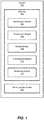
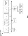
- FIG. 1 is a block diagram of an example system 100 for improving forwarding capabilities during route convergence.
- example system 100 may include one or more modules 102 for performing one or more tasks.
- example system 100 may include an identification module 104 that identifies, at an upstream network device, a set of updated routes that define network paths that have each experienced at least one topology change since the upstream network device last converged with a downstream network device.
- Example system 100 may also include a prioritization module 106 that determines, at the upstream network device, levels of priority for the set of updated routes based at least in part on amounts of traffic that traverse the network paths defined by the set of updated routes.
- Example system 100 may further include a sorting module 108 that arranges, at the upstream network device, the set of updated routes in a prioritized order in accordance with the levels of priority determined based at least in part on the amounts of traffic that traverse the network paths.
- example system 100 may include a convergence module 110 that converges the upstream network device with the downstream network device by sending the set of updated routes in the prioritized order to the downstream network device such that the downstream network device is able to forward traffic by way of higher priority routes within the set of updated routes before lower priority routes within the set of updated routes.
- example system 100 may include a monitoring module 112 that monitors the amounts of traffic that traverse the network paths defined by the set of updated routes by way of a traffic flow analysis.
- modules 102 in FIG. 1 may represent portions of a single module or application (such as a network operating system).
- one or more of modules 102 in FIG. 1 may represent one or more software applications or programs that, when executed by a computing device, cause the computing device to perform one or more tasks.
- one or more of modules 102 may represent software modules stored and configured to run on one or more computing devices, such as any of the devices illustrated in FIG. 2 (e.g., network devices 202, 204, 206, and/or 208), and/or computing system 600 in FIG. 6 .
- One or more of modules 102 in FIG. 1 may also represent all or portions of one or more special-purpose computers configured to perform one or more tasks.
- system 100 may also include one or more sets of updated routes, such as set of updated routes 120.
- set of updated routes 120 may include and/or represent routes that define paths to destinations whether inside or outside a network.
- path generally refers to any series of links and/or devices that facilitate communication and/or the flow of traffic between a source and a destination within a network and/or across networks.
- route generally refers to any type or form of information, data, and/or representation that indicates and/or identifies a path within a network and/or across networks.
- set of updated routes 120 may be maintained and/or stored in a routing table and/or a Routing Information Base (RIB).
- the routing table and/or RIB may include and/or represent any type or form of database and/or table that includes, stores, and/or identifies one or more routes within a routing engine of a router.
- set of updated routes 120 may be maintained and/or stored in a forwarding table and/or a Forwarding Information Base (FIB).
- the forwarding table and/or FIB may include and/or represent any type or form of database and/or table that includes, stores, and/or identifies one or more active routes within a forwarding engine (sometimes also referred to as a packet forwarding engine) of a router.
- a forwarding engine sometimes also referred to as a packet forwarding engine
- Each route may indicate and/or identify various information and/or data representative of a path.
- information and/or data include, without limitation, the Internet Protocol (IP) address of the destination device, the IP address of a gateway device, a routing prefix of the destination or gateway device, the IP address of the next hop, a network mask, combinations or variations of one or more of the same, and/or any other suitable information or data.
- IP Internet Protocol
- Example system 100 in FIG. 1 may be implemented in a variety of ways. For example, all or a portion of example system 100 may represent portions of example system 200 in FIG. 2 .
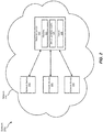
- system 200 may include a network 210 that supports and/or facilitates communication and/or data transfer among network devices 202, 204, 206, and 208 and/or various client devices (not illustrated in FIG. 2 ).
- FIG. 2 illustrates only network devices 202, 204, 206, and 208 within network 210, various other network devices and/or computing devices may represent part of network 210 and/or be included in network 210.
- network device 202 may be programmed with one or more of modules 102.
- network device 202 may include, store, and/or maintain set of updated routes 120. Additionally or alternatively, network device 202 may include and/or store a queue 220 that maintains set of updated routes 120 in a prioritized order to be sent to network devices 204, 206, and/or 208 during convergence.
- network devices 204, 206, and/or 208 may also be programmed with one or more of modules 102.
- one or more of modules 102 from FIG. 1 may, when executed by at least one processor of network device 202 in FIG. 2 , enable network device 202 to improve forwarding capabilities during route convergence.
- one or more of modules 102 may cause network device 202 to (1) identify, at network device 202, set of updated routes 120 that define network paths that have each experienced at least one topology change since network device 202 last converged with network devices 204, 206, and/or 208, (2) determine, at network device 202, levels of priority for set of updated routes 120 based at least in part on amounts of traffic that traverse the network paths defined by set of updated routes 120, (3) arranging, at network device 202, set of updated routes 120 in a prioritized order in accordance with the levels of priority determined based at least in part on the amounts of traffic that traverse the network paths, and then (4) converging network device 202 with network devices 204, 206, and/or 208 by sending set of updated routes 120 in the prioritized order
- Network devices 202, 204, 206, and/or 208 each generally represent any type or form of device, system, and/or mechanism that facilitates communication and/or network traffic among computing devices and/or within a network or across networks.
- network devices 202, 204, 206, and/or 208 may each represent a router. Additionally or alternatively, network devices 202, 204, 206, and/or 208 may each include and/or represent a gateway to a network.
- Examples of network devices 202, 204, 206, and/or 208 include, without limitation, routers (such as provider edge routers, hub routers, spoke routers, autonomous system boundary routers, and/or area border routers), switches, hubs, modems, bridges, repeaters, gateways, multiplexers, network adapters, network interfaces, network racks, chasses, servers, computing devices, virtual machines running on one or more of the same, portions of one or more of the same, combinations or variations of one or more of the same, and/or any other suitable network devices.
- routers such as provider edge routers, hub routers, spoke routers, autonomous system boundary routers, and/or area border routers
- switches such as provider edge routers, hub routers, spoke routers, autonomous system boundary routers, and/or area border routers
- switches such as provider edge routers, hub routers, spoke routers, autonomous system boundary routers, and/or area border routers
- switches such as provider edge routers, hub routers, spoke routers, autonomous system boundary routers
- Network 210 each generally represent to any type or form of medium and/or architecture that facilitates communication or data transfer.
- network 210 may facilitate traffic for subscribers of a service provider (such as AT&T, VERIZON WIRELESS, SPRINT, T-MOBILE, FACEBOOK, GOOGLE, INSTAGRAM, NETFLIX, AMAZON, YOUTUBE, CENTURY LINK, COMCAST, DIRECTV, and/or APPLE).
- a service provider such as AT&T, VERIZON WIRELESS, SPRINT, T-MOBILE, FACEBOOK, GOOGLE, INSTAGRAM, NETFLIX, AMAZON, YOUTUBE, CENTURY LINK, COMCAST, DIRECTV, and/or APPLE.
- network 210 examples include, without limitation, an MPLS network, an intranet, a Wide Area Network (WAN), a Local Area Network (LAN), a Personal Area Network (PAN), the Internet, Power Line Communications (PLC), a cellular network (e.g., a Global System for Mobile Communications (GSM) network), a peer network, portions of one or more of the same, combinations or variations of one or more of the same, and/or any other suitable networks.
- Network 210 may support and/or facilitate communication or data transfer using wireless and/or wired connections.
- FIG. 2 illustrates only a single network, alternative embodiments may include various other networks in addition to network 210. Additionally or alternatively, although FIG. 2 illustrates network 210 as a single entity, network 210 may alternatively include and/or represent a plurality of networks and/or subnetworks.
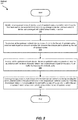
- FIG. 3 is a flow diagram of an example computer-implemented method 300 for improving forwarding capabilities during route convergence.
- the steps shown in FIG. 3 may be performed by any suitable computer-executable code and/or computing system. In some embodiments, the steps shown in FIG. 3 may be performed by one or more of the components of system 100 in FIG. 1 , system 200 in FIG. 2 , and/or computing system 600 in FIG. 6 .
- one or more of the systems described herein may identify, at an upstream network device, a set of updated routes that define network paths that have each experienced at least one topology change since the upstream network device last converged with a downstream network device.
- identification module 104 may, as part of network device 202 in FIG. 2 , identify set of updated routes 120 that define network paths that have each experienced at least one topology change since network device 202 last converged with network device 204, 206, and/or 208.
- Examples of such a topology change include, without limitation, adding a network device to a network, removing a network device from a network, a failure of network device within a network, a failure of communication port, link, and/or connection within a network, combinations or variations of one or more of the same, and/or any suitable topology change.
- upstream network device generally refers to any type or form of network device that resides more toward the server-side, and/or further away from the client-side, than a certain point of reference.
- downstream network device generally refers to any type or form of network device that resides more toward the client-side, and/or further away from the server-side, than a certain point of reference.
- identification module 104 may identify set of updated routes 120 based at least in part on any delays, disruptions, and/or failures detected in connection with traffic traversing network 210.
- monitoring module 112 may, as part of network device 202 in FIG. 2 and/or another network device (not necessarily illustrated in FIG. 2 ), monitor traffic received and/or transmitted by network device 202 within network 210.
- monitoring module 112 may detect any delays, disruptions, and/or failures that occur in connection with traffic transmitted by network device 202.
- Identification module 104 may then determine that some of these delays, disruptions, and/or failures resulted from a change in the topology of network 210. In response to this determination, identification module 104 may identify any routes involving the portion of network 210 that experienced the topology change and/or are affected by the same.
- identification module 104 may identify set of updated routes 120 based at least in part on a notification and/or advertisement indicating a change in the topology of network 210. For example, identification module 104 may receive a notification and/or advertisement indicating that a network device has been added to network 210. In one example, the notification and/or advertisement may be initiated by the newly added network device itself. In another example, the notification and/or advertisement may be initiated by a computing device operated by a network administrator involved in adding the network device to network 210. In response to the notification and/or advertisement, identification module 104 may identify any routes that are affected by the addition of the network device.
- identification module 104 may receive a notification and/or advertisement indicating that a network device has been removed from network 210.
- the notification and/or advertisement may be initiated by another network device that detected the removal of the network device from network 210.
- the notification and/or advertisement may be initiated by a computing device operated by a network administrator involved in removing the network device from network 210.
- identification module 104 may identify any routes that are affected by the removal of the network device.
- identification module 104 may receive a notification and/or advertisement indicating that certain traffic was dropped and/or unable to reach its destination due at least in part to a failure. Identification module 104 may then determine that the notification and/or advertisement resulted from a change in the topology of network 210. In response to this determination, identification module 104 may identify any routes involving the portion of network 210 that experienced the topology change and/or are affected by the same.
- network device 202 may modify and/or update those routes to account for the topology change. For example, network device 202 may modify and/or update the affected routes such that they define network paths that lead to the correct destination and/or are able to reach the same. In this example, these modified routes may constitute and/or represent alternatives to those routes that defined network paths that were affected by the topology change.
- the change to the topology of network 210 may have occurred since the last time that network device 202 converged with network device 204, 206, and/or 208.
- the addition or removal of a network device may have occurred after the last time that network device 202 converged with network device 204, 206, and/or 208.
- the failure of a network device may have occurred after the last time that network device 202 converged with network device 204, 206, and/or 208.
- network device 202 may need to converge with network device 204, 206, and/or 208 again to ensure that they effectively agree, by way of their routing tables, on the current network topology.
- one or more of the systems described herein may determine, at the upstream network device, levels of priority for the set of updated routes based at least in part on amounts of traffic that traverse the network paths defined by the set of updated routes.
- prioritization module 106 may, as part of network device 202 in FIG. 2 , determine levels of priority for set of updated routes 120 based at least in part on amounts of traffic that traverse the network paths defined by set of updated routes 120.
- the levels of priority may be relative in nature (e.g., prioritization of one route relative to another). Additionally or alternatively, the levels of priority may indicate that the routes belong to a certain class (e.g., high priority, moderate priority, and/or low priority).
- prioritization module 106 may determine the levels of priority for set of updated routes 120 based at least in part on a traffic flow analysis. For example, monitoring module 112 may monitor the amounts of traffic that traverse the network paths defined by set of updated routes 120. In this example, identification module 104 may determine which updated route defines the network path that carries the most traffic. Prioritization module 106 may then determine that this high-traffic updated route has the highest priority. Additionally or alternatively, prioritization module 106 may assign this high-traffic updated route the highest priority.
- identification module 104 may determine which updated route defines the network path that carries the least traffic. Prioritization module 106 may then determine that this low-traffic updated route has the lowest priority. Additionally or alternatively, prioritization module 106 may assign this low-traffic updated route the lowest priority.
- prioritization module 106 may rank set of updated routes 120 from highest priority to lowest priority. For example, prioritization module 106 may apply and/or assign the highest priority level to the updated route that carries the most traffic among set of updated routes 120. In this example, prioritization module 106 may apply and/or assign the second highest priority level to the updated route that carries the second most traffic among set of updated routes 120. Additionally or alternatively, prioritization module 106 may apply and/or assign the third highest priority level to the updated route that carries the third most traffic among set of updated routes 120.
- prioritization module 106 may apply and/or assign the lowest priority level to the updated route that carries the least traffic among set of updated routes 120.
- prioritization module 106 may apply and/or assign the second lowest priority level to the updated route that carries the second lowest traffic among set of updated routes 120.
- Prioritization module 106 may continue applying and/or assigning priority levels in this way for all of updated routes 120, thereby effectively ranking set of updated routes 120 from highest priority to lowest priority.
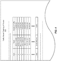
- FIG. 4 illustrates an example traffic-based ranking of updated routes 120.
- traffic-based ranking of updated routes 120 may identify updated routes (represented, in this example, by prefixes "64.15.112.0/20", “208.65.152.0/22”, “208.117.224.0/19", “128.47.209.0/18", "192.41.17.0/21”, “75.57.201.0/22", “102.2.65.0/18", and "82.92.156.0/16") according to their respective rankings (in this example, “1", “2", “3”, “4", "5", “6", “7", and "1,000,” respectively).
- These rankings may be based at least in part on the amount of traffic carried by the updated routes (in this example, " ⁇ 118,000,000”, “ ⁇ 112,000,000”, “ ⁇ 110,000,000”, “ ⁇ 105,000,000”, “ ⁇ 102,000,000”, “ ⁇ 100,000,000", “ ⁇ 92,000,000", and “ ⁇ 2,000,” respectively).
- the amount of traffic may be represented and/or measured by the number of flows, the number of packets, and/or the number of bytes carried by such routes.
- prioritization module 106 may assign a class designation to each of updated routes 120. For example, prioritization module 106 may assign a high-priority designation to each updated route that carries an amount of traffic that exceeds a high-traffic threshold. In this example, prioritization module 106 may assign a moderate-priority designation to each updated route that carries an amount of traffic that exceeds a moderate-traffic threshold but not the high-traffic threshold. Additionally or alternatively, prioritization module 106 may assign a low-priority designation to each updated route that carries an amount of traffic that does not reach the moderate-traffic threshold.
- prioritization module 106 may determine the levels of priority for set of updated routes 120 based at least in part on user input.
- identification module 104 may obtain user input that indicates a priority level selected by a network administrator for a route within set of updated routes 120. For example, identification module 104 may determine that a network administrator has entered user input indicating that a certain updated route should be assigned the highest priority regardless of the amount of traffic carried by that updated route. Prioritization module 106 may apply and/or assign the user-selected priority to the corresponding route based at least in part on the user input.
- identification module 104 may identify a route within set of updated routes 120 that has been prioritized based at least in part on the route's status being mission-critical. For example, a route within set of updated routes 120 may have been designated as being mission-critical.
- prioritization module 106 may apply and/or assign a priority level to the route due at least in part to that mission-critical designation regardless of the amount of traffic carried by the route. Accordingly, the mission-critical status may effectively increase the route's priority level above other routes that carry more traffic than the mission-critical route.
- mission-critical routes include, without limitation, routes related to emergency services (such as law enforcement, medical emergencies, and/or "911" services), routes related to military services, routes related to public safety, combinations or variations of one or more of the same, and/or any other suitable mission-critical routes.
- emergency services such as law enforcement, medical emergencies, and/or "911" services
- military services such as law enforcement, medical emergencies, and/or "911" services
- public safety such as public safety, combinations or variations of one or more of the same, and/or any other suitable mission-critical routes.
- one or more of the systems described herein may arranging, at the upstream network device, the set of updated routes in a prioritized order in accordance with the levels of priority determined based at least in part on the amounts of traffic that traverse the network paths.
- sorting module 108 may, as part of network device 202 in FIG. 2 , arrange set of updated routes 120 in a prioritized order in accordance with the levels of priority determined based at least in part on the amounts of traffic that traverse the network paths defined by set of updated routes 120.
- the term "prioritized order,” as used herein, generally refers to any type or form of arrangement, sequence, and/or order that reflects, follows, and/or coincides with priority levels of updated routes.
- sorting module 108 may arrange set of updated routes 120 in the prioritized order by reordering set of updated routes 120. For example, set of updated routes 120 may occupy queue 220 in FIG. 2 . In this example, set of updated routes 120 may originally be arranged out of order with respect to priority. Sorting module 108 may sort and/or reorder set of updated routes 120 in queue 220 according to the ranking of priority. In other words, sorting module 108 may effectively order set of updated routes 120 from highest priority to lowest priority in queue 220.
- the resulting prioritized order may include the route with the highest priority in the first location and the route with the lowest priority in the last location within queue 220.
- This prioritized order may enable the route with the highest priority to be the first one sent by network device 202 to network device 204, 206, and/or 208 during convergence.
- this prioritized order may enable the route with the second highest priority to be the second one sent by network device 202 to network device 204, 206, and/or 208 during convergence.
- the prioritized order may enable the route with the lowest priority to be the last one sent by network device 202 to network device 204, 206, and/or 208 during convergence.
- FIG. 5 illustrates an example representation of queue 220, which includes a set of updated routes arranged in a prioritized order.
- queue 220 in FIG. 5 may include a set of updated routes (represented, in this example, by prefixes "64.15.112.0/20", “208.65.152.0/22”, “208.117.224.0/19", “128.47.209.0/18", and "82.92.156.0/16") arranged in order of priority.
- the order of updated routes included in queue 220 in FIG. 5 may correspond to and/or follow traffic-based ranking 400 in FIG. 4 .
- 5 may enable the "64.15.112.0/20" route to be the first one sent by network device 202 to network device 204, 206, and/or 208, the "208.65.152.0/22" route to be the second one sent by network device 202 to network device 204, 206, and/or 208, and so on.
- sorting module 108 may position that route ahead of other routes that carry more traffic due at least in part to the route's user-selected priority level. In the event that an updated route has been prioritized based at least in part on the route's mission-critical status, sorting module 108 may position that route ahead of other routes that carry more traffic due at least in part to the route's mission-critical status.
- one or more of the systems described herein may converge the upstream network device with the downstream network device by sending the set of updated routes in the prioritized order to the downstream network device such that the downstream network device is able to forward traffic by way of higher priority updated routes before lower priority updates routes.
- convergence module 110 may, as part of network device 202 in FIG. 2 , direct network device 202 to converge with network device 204, 206, and/or 208.
- convergence module 110 may perform and/or facilitate this convergence process by sending set of updated routes 120 in the prioritized order to network device 204, 206, and/or 208.
- convergence module 110 may enable network device 204, 206, and/or 208 to forward traffic by way of higher priority routes within set of updated routes 120 before lower priority routes within set of updated routes 120.
- convergence module 110 may facilitate convergence among network devices 202, 204, 206, and/or 208 by way of a Border Gateway Protocol (BGP) convergence operation.
- BGP Border Gateway Protocol
- convergence module 110 may perform a BGP convergence operation with respect to network devices 202, 204, 206, and/or 208 by sending set of updated routes 120 from network device 202 to network device 204, 206, and/or 208 via BGP.
- convergence module 110 may send set of updated routes 120 from network device 202 to network device 204, 206, and/or 208 in the order shown in queue 220 in FIG. 2 .
- convergence module 110 may enable network device 204, 206, and/or 208 to begin forwarding traffic to the higher priority updated routes earlier than the lower priority updated routes during the convergence process.
- network device 204, 206, and/or 208 may be unable to forward traffic via an updated route until that updated route has been installed into the routing and forwarding tables. Since, in this example, set of updated routes 120 are sent in order of priority, network device 204, 206, and/or 208 may install updates to the important routes (e.g., high-traffic routes) sooner than the unimportant routes during the convergence process.
- convergence module 110 may enable network device 204, 206, and/or 208 not only to carry traffic prior to completion of the convergence process but also to carry traffic sooner than the unimportant routes during convergence, thereby potentially improving the forwarding capabilities of network device 204, 206, and/or 208 during route convergence.
- routers may be able to receive advertised updates to routes affected by topology changes in a prioritized order. By receiving these updates in the prioritized order, the routers may be able to install the updates to important routes before updates to unimportant routes during convergence. Moreover, by installing the updates to important routes in this way during convergence, the routers may be able to forward traffic by way of the important routes at an earlier point in the convergence process. Accordingly, these routers may not only be able to carry traffic prior to completion of the convergence process but also be able to carry traffic sooner than the unimportant routes during convergence.
- FIG. 6 is a block diagram of an example computing system 600 capable of implementing and/or being used in connection with one or more of the embodiments described and/or illustrated herein.
- all or a portion of computing system 600 may perform and/or be a means for performing, either alone or in combination with other elements, one or more of the steps described in connection with FIG. 3 .
- All or a portion of computing system 600 may also perform and/or be a means for performing and/or implementing any other steps, methods, or processes described and/or illustrated herein.
- computing system 600 may include an apparatus that performs and/or constitutes a means for performing and/or implementing any other steps, methods, or processes described and/or illustrated herein.
- Computing system 600 broadly represents any type or form of electrical load, including a single or multi-processor computing device or system capable of executing computer-readable instructions.
- Examples of computing system 600 include, without limitation, workstations, laptops, client-side terminals, servers, distributed computing systems, mobile devices, network switches, network routers (e.g., backbone routers, edge routers, core routers, mobile service routers, broadband routers, etc.), network appliances (e.g., network security appliances, network control appliances, network timing appliances, SSL VPN (Secure Sockets Layer Virtual Private Network) appliances, etc.), network controllers, gateways (e.g., service gateways, mobile packet gateways, multi-access gateways, security gateways, etc.), and/or any other type or form of computing system or device.
- network routers e.g., backbone routers, edge routers, core routers, mobile service routers, broadband routers, etc.
- network appliances e.g., network security appliances, network control appliances, network timing appliances, SSL VPN
- Computing system 600 may be programmed, configured, and/or otherwise designed to comply with one or more networking protocols. According to certain embodiments, computing system 600 may be designed to work with protocols of one or more layers of the Open Systems Interconnection (OSI) reference model, such as a physical layer protocol, a link layer protocol, a network layer protocol, a transport layer protocol, a session layer protocol, a presentation layer protocol, and/or an application layer protocol.
- OSI Open Systems Interconnection
- computing system 600 may include a network device configured according to a Universal Serial Bus (USB) protocol, an Institute of Electrical and Electronics Engineers (IEEE) 1394 protocol, an Ethernet protocol, a T1 protocol, a Synchronous Optical Networking (SONET) protocol, a Synchronous Digital Hierarchy (SDH) protocol, an Integrated Services Digital Network (ISDN) protocol, an Asynchronous Transfer Mode (ATM) protocol, a Point-to-Point Protocol (PPP), a Point-to-Point Protocol over Ethernet (PPPoE), a Point-to-Point Protocol over ATM (PPPoA), a Bluetooth protocol, an IEEE 802.XX protocol, a frame relay protocol, a token ring protocol, a spanning tree protocol, and/or any other suitable protocol.
- Computing system 600 may include various network and/or computing components.
- computing system 600 may include at least one processor 614 and a system memory 616.
- Processor 614 generally represents any type or form of processing unit capable of processing data or interpreting and executing instructions.
- processor 614 may represent an application-specific integrated circuit (ASIC), a system on a chip (e.g., a network processor), a hardware accelerator, a general purpose processor, and/or any other suitable processing element.
- ASIC application-specific integrated circuit
- system on a chip e.g., a network processor
- hardware accelerator e.g., a hardware accelerator
- general purpose processor e.g., a general purpose processor, and/or any other suitable processing element.
- Processor 614 may process data according to one or more of the networking protocols discussed above. For example, processor 614 may execute or implement a portion of a protocol stack, may process packets, may perform memory operations (e.g., queuing packets for later processing), may execute end-user applications, and/or may perform any other processing tasks.
- processor 614 may execute or implement a portion of a protocol stack, may process packets, may perform memory operations (e.g., queuing packets for later processing), may execute end-user applications, and/or may perform any other processing tasks.
- System memory 616 generally represents any type or form of volatile or non-volatile storage device or medium capable of storing data and/or other computer-readable instructions. Examples of system memory 616 include, without limitation, Random Access Memory (RAM), Read Only Memory (ROM), flash memory, or any other suitable memory device. Although not required, in certain embodiments computing system 600 may include both a volatile memory unit (such as, for example, system memory 616) and a non-volatile storage device (such as, for example, primary storage device 632, as described in detail below). System memory 616 may be implemented as shared memory and/or distributed memory in a network device. Furthermore, system memory 616 may store packets and/or other information used in networking operations. In one example, system memory 616 may include and/or store one or more of modules 102 from FIG. 1 .
- example computing system 600 may also include one or more components or elements in addition to processor 614 and system memory 616.
- computing system 600 may include a memory controller 618, an Input/Output (I/O) controller 620, and a communication interface 622, each of which may be interconnected via communication infrastructure 612.
- Communication infrastructure 612 generally represents any type or form of infrastructure capable of facilitating communication between one or more components of a computing device. Examples of communication infrastructure 612 include, without limitation, a communication bus (such as a Serial ATA (SATA), an Industry Standard Architecture (ISA), a Peripheral Component Interconnect (PCI), a PCI Express (PCIe), and/or any other suitable bus), and a network.
- SATA Serial ATA
- ISA Industry Standard Architecture
- PCI Peripheral Component Interconnect
- PCIe PCI Express
- Memory controller 618 generally represents any type or form of device capable of handling memory or data or controlling communication between one or more components of computing system 600.
- memory controller 618 may control communication between processor 614, system memory 616, and I/O controller 620 via communication infrastructure 612.
- memory controller 618 may include a Direct Memory Access (DMA) unit that may transfer data (e.g., packets) to or from a link adapter.
- DMA Direct Memory Access
- I/O controller 620 generally represents any type or form of device or module capable of coordinating and/or controlling the input and output functions of a computing device.
- I/O controller 620 may control or facilitate transfer of data between one or more elements of computing system 600, such as processor 614, system memory 616, communication interface 622, and storage interface 630.
- Communication interface 622 broadly represents any type or form of communication device or adapter capable of facilitating communication between example computing system 600 and one or more additional devices.
- communication interface 622 may facilitate communication between computing system 600 and a private or public network including additional computing systems.
- Examples of communication interface 622 include, without limitation, a link adapter, a wired network interface (such as a network interface card), a wireless network interface (such as a wireless network interface card), and any other suitable interface.
- communication interface 622 may provide a direct connection to a remote server via a direct link to a network, such as the Internet.
- Communication interface 622 may also indirectly provide such a connection through, for example, a local area network (such as an Ethernet network), a personal area network, a wide area network, a private network (e.g., a virtual private network), a telephone or cable network, a cellular telephone connection, a satellite data connection, or any other suitable connection.
- a local area network such as an Ethernet network
- a personal area network such as an Ethernet network
- a wide area network such as a wide area network
- a private network e.g., a virtual private network
- telephone or cable network such as a cellular telephone connection
- satellite data connection such as satellite data network
- communication interface 622 may also represent a host adapter configured to facilitate communication between computing system 600 and one or more additional network or storage devices via an external bus or communications channel.
- host adapters include, without limitation, Small Computer System Interface (SCSI) host adapters, Universal Serial Bus (USB) host adapters, IEEE 1394 host adapters, Advanced Technology Attachment (ATA), Parallel ATA (PATA), Serial ATA (SATA), and External SATA (eSATA) host adapters, Fibre Channel interface adapters, Ethernet adapters, or the like.
- Communication interface 622 may also enable computing system 600 to engage in distributed or remote computing. For example, communication interface 622 may receive instructions from a remote device or send instructions to a remote device for execution.
- example computing system 600 may also include a primary storage device 632 and/or a backup storage device 634 coupled to communication infrastructure 612 via a storage interface 630.
- Storage devices 632 and 634 generally represent any type or form of storage device or medium capable of storing data and/or other computer-readable instructions.
- storage devices 632 and 634 may represent a magnetic disk drive (e.g., a so-called hard drive), a solid state drive, a floppy disk drive, a magnetic tape drive, an optical disk drive, a flash drive, or the like.
- Storage interface 630 generally represents any type or form of interface or device for transferring data between storage devices 632 and 634 and other components of computing system 600.
- storage devices 632 and 634 may be configured to read from and/or write to a removable storage unit configured to store computer software, data, or other computer-readable information.
- suitable removable storage units include, without limitation, a floppy disk, a magnetic tape, an optical disk, a flash memory device, or the like.
- Storage devices 632 and 634 may also include other similar structures or devices for allowing computer software, data, or other computer-readable instructions to be loaded into computing system 600.
- storage devices 632 and 634 may be configured to read and write software, data, or other computer-readable information.
- Storage devices 632 and 634 may be a part of computing system 600 or may be separate devices accessed through other interface systems.
- computing system 600 may also employ any number of software, firmware, and/or hardware configurations.
- one or more of the example embodiments disclosed herein may be encoded as a computer program (also referred to as computer software, software applications, computer-readable instructions, or computer control logic) on a computer-readable medium.
- computer-readable medium generally refers to any form of device, carrier, or medium capable of storing or carrying computer-readable instructions.
- Examples of computer-readable media include, without limitation, transmission-type media, such as carrier waves, transitory-type media, and non-transitory-type media, such as magnetic-storage media (e.g., hard disk drives and floppy disks), optical-storage media (e.g., Compact Disks (CDs) and Digital Video Disks (DVDs)), electronic-storage media (e.g., solid-state drives and flash media), and other distribution systems.
- transmission-type media such as carrier waves
- transitory-type media such as magnetic-storage media (e.g., hard disk drives and floppy disks), optical-storage media (e.g., Compact Disks (CDs) and Digital Video Disks (DVDs)), electronic-storage media (e.g., solid-state drives and flash media), and other distribution systems.
- non-transitory-type media such as magnetic-storage media (e.g., hard disk drives and floppy disks), optical-storage media (e.
- system 100 in FIG. 1 may represent portions of a cloud-computing or network-based environment.
- Cloud-computing and network-based environments may provide various services and applications via the Internet. These cloud-computing and network-based services (e.g., software as a service, platform as a service, infrastructure as a service, etc.) may be accessible through a web browser or other remote interface.
- Various functions described herein may also provide network switching capabilities, gateway access capabilities, network security functions, content caching and delivery services for a network, network control services, and/or and other networking functionality.
- one or more of the modules described herein may transform data, physical devices, and/or representations of physical devices from one form to another. Additionally or alternatively, one or more of the modules recited herein may transform a processor, volatile memory, non-volatile memory, and/or any other portion of a physical computing device from one form to another by executing on the computing device, storing data on the computing device, and/or otherwise interacting with the computing device.
Description
- Networks often experience topology changes that necessitate route updates. For example, an administrator may add a router to a network and/or remove a router from the network. Additionally or alternatively, a physical link in the network may suffer a failure that prevents the flow of network traffic via certain paths. As a result, the routers within the network may need to modify routes affected by topology changes within their routing tables and/or forwarding tables. To facilitate modifying the affected routes in this way, the routers may converge with one another by advertising updates to the affected routes.
- In this context, the term "convergence" may refer to the process of updating affected routes to account for topology changes within a network. Traditional routers may advertise updates to the affected routes by sending the updates to one another. Some of the affected routes may be more important than others. For example, one of the affected routes may carry a lot of traffic, but another one of the affected routes may carry practically no traffic at all.
- Unfortunately, these traditional routers may be unable to forward traffic via the affected routes until the updates have been installed into the routers' routing and forwarding tables. Moreover, the order in which these updates are sent by the traditional routers may have little, if any, meaning or purpose. Since the updates are sent in no particular order during convergence, these traditional routers may end up installing updates to very important routes (e.g., high-traffic routes) after a long queue of updates to unimportant routes (e.g., low-traffic routes). As a result, the traditional routers may be unable to forward traffic via the very important routes until after the updates to the unimportant routes have been installed, thereby potentially causing delays and/or disruptions in the routers' forwarding capabilities.
- The instant disclosure, therefore, identifies and addresses a need for additional and improved methods, systems, and apparatuses for improving forwarding capabilities during route convergence.
-
US 8 737 406 B1 relates to a method for transmitting IP routes to prioritize convergence.US 2009/109852 A1 relates to statistics based forwarding information base repopulation. - Particular aspects and embodiments are set out in the appended independent and dependent claims.
- The accompanying drawings illustrate a number of example embodiments and are a part of the specification. Together with the following description, these drawings demonstrate and explain various principles of the instant disclosure.
-
FIG. 1 is a block diagram of an example system for improving forwarding capabilities during route convergence. -
FIG. 2 is a block diagram of an example system for improving forwarding capabilities during route convergence. -
FIG. 3 is a flow diagram of an example method for improving forwarding capabilities during route convergence. -
FIG. 4 is an illustration of an example traffic-based ranking of updated routes. -
FIG. 5 is an illustration of an example queue that includes a set of updated routes arranged in a prioritized order. -
FIG. 6 is a block diagram of an example computing system capable of implementing and/or being used in connection with one or more of the embodiments described and/or illustrated herein. - Throughout the drawings, identical reference characters and descriptions indicate similar, but not necessarily identical, elements. While the example embodiments described herein are susceptible to various modifications and alternative forms, specific embodiments have been shown by way of example in the drawings and will be described in detail herein. However, the example embodiments described herein are not intended to be limited to the particular forms disclosed. Rather, the instant disclosure covers all modifications, equivalents, and alternatives falling within the scope of the appended claims.
- The present disclosure describes various methods, systems, and apparatuses for improving forwarding capabilities during route convergence. As will be explained in greater detail below, embodiments of the instant disclosure may enable routers to receive advertised updates to routes affected by topology changes in a prioritized order. As a result, embodiments of the instant disclosure may enable these routers to install updates to important routes before updates to unimportant routes during convergence. By installing updates to important routes before updates to unimportant routes in this way, embodiments of the instant disclosure may enable these routers to forward traffic by way of the important routes at an earlier point in the convergence process. In other words, embodiments of the instant disclosure may ensure that the important routes are not only able to carry traffic prior to completion of the convergence process but also able to carry traffic sooner than the unimportant routes during convergence.
- The term "convergence" and the phrase "to converge," as used herein, generally refer to the process of updating routes affected by topology changes within a network. In this context, a set of network devices may fully converge once they have completed exchanging any updates to routes affected by topology changes such that the devices' routing tables include the same routes or at least non-contradictory routes. In other words, convergence may reach a state of completion when the network devices effectively agree, by way of their routing tables, on the current network topology. Accordingly, the routing tables of these converged network devices may include only routes that are consistent with one another.
- The following will provide, with reference to
FIGS. 1 and2 , detailed descriptions of example systems for improving forwarding capabilities during route convergence. Detailed descriptions of corresponding computer-implemented methods will be provided in connection withFIG. 3 . Detailed descriptions of an example traffic-based ranking of updated routes will be provided in connection withFIG. 4 . Detailed descriptions of an example queue that includes a set of updated routes arranged in a prioritized order will be provided in connection withFIG. 5 . In addition, detailed descriptions of an example computing system capable of implementing one or more of the embodiments described herein will be provided in connection withFIG. 6 . -
FIG. 1 is a block diagram of anexample system 100 for improving forwarding capabilities during route convergence. As illustrated in this figure,example system 100 may include one ormore modules 102 for performing one or more tasks. For example, and as will be explained in greater detail below,example system 100 may include anidentification module 104 that identifies, at an upstream network device, a set of updated routes that define network paths that have each experienced at least one topology change since the upstream network device last converged with a downstream network device.Example system 100 may also include aprioritization module 106 that determines, at the upstream network device, levels of priority for the set of updated routes based at least in part on amounts of traffic that traverse the network paths defined by the set of updated routes.Example system 100 may further include asorting module 108 that arranges, at the upstream network device, the set of updated routes in a prioritized order in accordance with the levels of priority determined based at least in part on the amounts of traffic that traverse the network paths. - In addition, and as will be described in greater detail below,
example system 100 may include aconvergence module 110 that converges the upstream network device with the downstream network device by sending the set of updated routes in the prioritized order to the downstream network device such that the downstream network device is able to forward traffic by way of higher priority routes within the set of updated routes before lower priority routes within the set of updated routes. Moreover,example system 100 may include amonitoring module 112 that monitors the amounts of traffic that traverse the network paths defined by the set of updated routes by way of a traffic flow analysis. Although illustrated as separate elements, one or more ofmodules 102 inFIG. 1 may represent portions of a single module or application (such as a network operating system). - In certain embodiments, one or more of
modules 102 inFIG. 1 may represent one or more software applications or programs that, when executed by a computing device, cause the computing device to perform one or more tasks. For example, and as will be described in greater detail below, one or more ofmodules 102 may represent software modules stored and configured to run on one or more computing devices, such as any of the devices illustrated inFIG. 2 (e.g.,network devices computing system 600 inFIG. 6 . One or more ofmodules 102 inFIG. 1 may also represent all or portions of one or more special-purpose computers configured to perform one or more tasks. - As illustrated in
FIG. 1 ,system 100 may also include one or more sets of updated routes, such as set ofupdated routes 120. In one example, set ofupdated routes 120 may include and/or represent routes that define paths to destinations whether inside or outside a network. The term "path," as used herein, generally refers to any series of links and/or devices that facilitate communication and/or the flow of traffic between a source and a destination within a network and/or across networks. The term "route," as used herein, generally refers to any type or form of information, data, and/or representation that indicates and/or identifies a path within a network and/or across networks. - In one example, set of
updated routes 120 may be maintained and/or stored in a routing table and/or a Routing Information Base (RIB). The routing table and/or RIB may include and/or represent any type or form of database and/or table that includes, stores, and/or identifies one or more routes within a routing engine of a router. Additionally or alternatively, set of updatedroutes 120 may be maintained and/or stored in a forwarding table and/or a Forwarding Information Base (FIB). The forwarding table and/or FIB may include and/or represent any type or form of database and/or table that includes, stores, and/or identifies one or more active routes within a forwarding engine (sometimes also referred to as a packet forwarding engine) of a router. - Each route may indicate and/or identify various information and/or data representative of a path. Examples of such information and/or data include, without limitation, the Internet Protocol (IP) address of the destination device, the IP address of a gateway device, a routing prefix of the destination or gateway device, the IP address of the next hop, a network mask, combinations or variations of one or more of the same, and/or any other suitable information or data.
-
Example system 100 inFIG. 1 may be implemented in a variety of ways. For example, all or a portion ofexample system 100 may represent portions ofexample system 200 inFIG. 2 . As shown inFIG. 2 ,system 200 may include anetwork 210 that supports and/or facilitates communication and/or data transfer amongnetwork devices FIG. 2 ). AlthoughFIG. 2 illustratesonly network devices network 210, various other network devices and/or computing devices may represent part ofnetwork 210 and/or be included innetwork 210. - In one example,
network device 202 may be programmed with one or more ofmodules 102. In this example,network device 202 may include, store, and/or maintain set of updatedroutes 120. Additionally or alternatively,network device 202 may include and/or store aqueue 220 that maintains set of updatedroutes 120 in a prioritized order to be sent tonetwork devices FIG. 2 ,network devices modules 102. - In one example, one or more of
modules 102 fromFIG. 1 may, when executed by at least one processor ofnetwork device 202 inFIG. 2 , enablenetwork device 202 to improve forwarding capabilities during route convergence. For example, and as will be described in greater detail below, one or more ofmodules 102 may causenetwork device 202 to (1) identify, atnetwork device 202, set of updatedroutes 120 that define network paths that have each experienced at least one topology change sincenetwork device 202 last converged withnetwork devices network device 202, levels of priority for set of updatedroutes 120 based at least in part on amounts of traffic that traverse the network paths defined by set of updatedroutes 120, (3) arranging, atnetwork device 202, set of updatedroutes 120 in a prioritized order in accordance with the levels of priority determined based at least in part on the amounts of traffic that traverse the network paths, and then (4) convergingnetwork device 202 withnetwork devices routes 120 in the prioritized order to networkdevices routes 120 before lower priority routes within set of updatedroute 120. -
Network devices network devices network devices network devices -
Network 210 each generally represent to any type or form of medium and/or architecture that facilitates communication or data transfer. In one example,network 210 may facilitate traffic for subscribers of a service provider (such as AT&T, VERIZON WIRELESS, SPRINT, T-MOBILE, FACEBOOK, GOOGLE, INSTAGRAM, NETFLIX, AMAZON, YOUTUBE, CENTURY LINK, COMCAST, DIRECTV, and/or APPLE). Examples ofnetwork 210 include, without limitation, an MPLS network, an intranet, a Wide Area Network (WAN), a Local Area Network (LAN), a Personal Area Network (PAN), the Internet, Power Line Communications (PLC), a cellular network (e.g., a Global System for Mobile Communications (GSM) network), a peer network, portions of one or more of the same, combinations or variations of one or more of the same, and/or any other suitable networks.Network 210 may support and/or facilitate communication or data transfer using wireless and/or wired connections. AlthoughFIG. 2 illustrates only a single network, alternative embodiments may include various other networks in addition tonetwork 210. Additionally or alternatively, althoughFIG. 2 illustratesnetwork 210 as a single entity,network 210 may alternatively include and/or represent a plurality of networks and/or subnetworks. -
FIG. 3 is a flow diagram of an example computer-implementedmethod 300 for improving forwarding capabilities during route convergence. The steps shown inFIG. 3 may be performed by any suitable computer-executable code and/or computing system. In some embodiments, the steps shown inFIG. 3 may be performed by one or more of the components ofsystem 100 inFIG. 1 ,system 200 inFIG. 2 , and/orcomputing system 600 inFIG. 6 . - As illustrated in
FIG. 3 , atstep 310 one or more of the systems described herein may identify, at an upstream network device, a set of updated routes that define network paths that have each experienced at least one topology change since the upstream network device last converged with a downstream network device. For example,identification module 104 may, as part ofnetwork device 202 inFIG. 2 , identify set of updatedroutes 120 that define network paths that have each experienced at least one topology change sincenetwork device 202 last converged withnetwork device - The term "upstream network device," as used herein, generally refers to any type or form of network device that resides more toward the server-side, and/or further away from the client-side, than a certain point of reference. In contrast, the term "downstream network device," as used herein, generally refers to any type or form of network device that resides more toward the client-side, and/or further away from the server-side, than a certain point of reference.
- The systems described herein may perform
step 310 in a variety of ways and/or contexts. In some examples,identification module 104 may identify set of updatedroutes 120 based at least in part on any delays, disruptions, and/or failures detected in connection withtraffic traversing network 210. For example,monitoring module 112 may, as part ofnetwork device 202 inFIG. 2 and/or another network device (not necessarily illustrated inFIG. 2 ), monitor traffic received and/or transmitted bynetwork device 202 withinnetwork 210. In this example,monitoring module 112 may detect any delays, disruptions, and/or failures that occur in connection with traffic transmitted bynetwork device 202.Identification module 104 may then determine that some of these delays, disruptions, and/or failures resulted from a change in the topology ofnetwork 210. In response to this determination,identification module 104 may identify any routes involving the portion ofnetwork 210 that experienced the topology change and/or are affected by the same. - In some examples,
identification module 104 may identify set of updatedroutes 120 based at least in part on a notification and/or advertisement indicating a change in the topology ofnetwork 210. For example,identification module 104 may receive a notification and/or advertisement indicating that a network device has been added tonetwork 210. In one example, the notification and/or advertisement may be initiated by the newly added network device itself. In another example, the notification and/or advertisement may be initiated by a computing device operated by a network administrator involved in adding the network device to network 210. In response to the notification and/or advertisement,identification module 104 may identify any routes that are affected by the addition of the network device. - Additionally or alternatively,
identification module 104 may receive a notification and/or advertisement indicating that a network device has been removed fromnetwork 210. In one example, the notification and/or advertisement may be initiated by another network device that detected the removal of the network device fromnetwork 210. In another example, the notification and/or advertisement may be initiated by a computing device operated by a network administrator involved in removing the network device fromnetwork 210. In response to the notification and/or advertisement,identification module 104 may identify any routes that are affected by the removal of the network device. - As another example,
identification module 104 may receive a notification and/or advertisement indicating that certain traffic was dropped and/or unable to reach its destination due at least in part to a failure.Identification module 104 may then determine that the notification and/or advertisement resulted from a change in the topology ofnetwork 210. In response to this determination,identification module 104 may identify any routes involving the portion ofnetwork 210 that experienced the topology change and/or are affected by the same. - Upon identification of the routes that define network paths affected by the topology change,
network device 202 may modify and/or update those routes to account for the topology change. For example,network device 202 may modify and/or update the affected routes such that they define network paths that lead to the correct destination and/or are able to reach the same. In this example, these modified routes may constitute and/or represent alternatives to those routes that defined network paths that were affected by the topology change. - In one example, the change to the topology of
network 210 may have occurred since the last time thatnetwork device 202 converged withnetwork device network device 202 converged withnetwork device network device 202 converged withnetwork device network device 202 may need to converge withnetwork device - Returning to
FIG. 3 , atstep 320 one or more of the systems described herein may determine, at the upstream network device, levels of priority for the set of updated routes based at least in part on amounts of traffic that traverse the network paths defined by the set of updated routes. For example,prioritization module 106 may, as part ofnetwork device 202 inFIG. 2 , determine levels of priority for set of updatedroutes 120 based at least in part on amounts of traffic that traverse the network paths defined by set of updatedroutes 120. In one example, the levels of priority may be relative in nature (e.g., prioritization of one route relative to another). Additionally or alternatively, the levels of priority may indicate that the routes belong to a certain class (e.g., high priority, moderate priority, and/or low priority). - The systems described herein may perform
step 320 in a variety of ways and/or contexts. In some examples,prioritization module 106 may determine the levels of priority for set of updatedroutes 120 based at least in part on a traffic flow analysis. For example,monitoring module 112 may monitor the amounts of traffic that traverse the network paths defined by set of updatedroutes 120. In this example,identification module 104 may determine which updated route defines the network path that carries the most traffic.Prioritization module 106 may then determine that this high-traffic updated route has the highest priority. Additionally or alternatively,prioritization module 106 may assign this high-traffic updated route the highest priority. - Similarly,
identification module 104 may determine which updated route defines the network path that carries the least traffic.Prioritization module 106 may then determine that this low-traffic updated route has the lowest priority. Additionally or alternatively,prioritization module 106 may assign this low-traffic updated route the lowest priority. - In one example,
prioritization module 106 may rank set of updatedroutes 120 from highest priority to lowest priority. For example,prioritization module 106 may apply and/or assign the highest priority level to the updated route that carries the most traffic among set of updatedroutes 120. In this example,prioritization module 106 may apply and/or assign the second highest priority level to the updated route that carries the second most traffic among set of updatedroutes 120. Additionally or alternatively,prioritization module 106 may apply and/or assign the third highest priority level to the updated route that carries the third most traffic among set of updatedroutes 120. - Continuing with this example,
prioritization module 106 may apply and/or assign the lowest priority level to the updated route that carries the least traffic among set of updatedroutes 120. In this example,prioritization module 106 may apply and/or assign the second lowest priority level to the updated route that carries the second lowest traffic among set of updatedroutes 120.Prioritization module 106 may continue applying and/or assigning priority levels in this way for all of updatedroutes 120, thereby effectively ranking set of updatedroutes 120 from highest priority to lowest priority. -
FIG. 4 illustrates an example traffic-based ranking of updatedroutes 120. As illustrated inFIG. 4 , traffic-based ranking of updatedroutes 120 may identify updated routes (represented, in this example, by prefixes "64.15.112.0/20", "208.65.152.0/22", "208.117.224.0/19", "128.47.209.0/18", "192.41.17.0/21", "75.57.201.0/22", "102.2.65.0/18", and "82.92.156.0/16") according to their respective rankings (in this example, "1", "2", "3", "4", "5", "6", "7", and "1,000," respectively). These rankings may be based at least in part on the amount of traffic carried by the updated routes (in this example, "∼118,000,000", "∼112,000,000", "∼110,000,000", "∼105,000,000", "∼102,000,000", "∼100,000,000", "∼92,000,000", and "∼2,000," respectively). The amount of traffic may be represented and/or measured by the number of flows, the number of packets, and/or the number of bytes carried by such routes. - In one example,
prioritization module 106 may assign a class designation to each of updatedroutes 120. For example,prioritization module 106 may assign a high-priority designation to each updated route that carries an amount of traffic that exceeds a high-traffic threshold. In this example,prioritization module 106 may assign a moderate-priority designation to each updated route that carries an amount of traffic that exceeds a moderate-traffic threshold but not the high-traffic threshold. Additionally or alternatively,prioritization module 106 may assign a low-priority designation to each updated route that carries an amount of traffic that does not reach the moderate-traffic threshold. - In some examples,
prioritization module 106 may determine the levels of priority for set of updatedroutes 120 based at least in part on user input. In one example,identification module 104 may obtain user input that indicates a priority level selected by a network administrator for a route within set of updatedroutes 120. For example,identification module 104 may determine that a network administrator has entered user input indicating that a certain updated route should be assigned the highest priority regardless of the amount of traffic carried by that updated route.Prioritization module 106 may apply and/or assign the user-selected priority to the corresponding route based at least in part on the user input. - Additionally or alternatively,
identification module 104 may identify a route within set of updatedroutes 120 that has been prioritized based at least in part on the route's status being mission-critical. For example, a route within set of updatedroutes 120 may have been designated as being mission-critical. In this example,prioritization module 106 may apply and/or assign a priority level to the route due at least in part to that mission-critical designation regardless of the amount of traffic carried by the route. Accordingly, the mission-critical status may effectively increase the route's priority level above other routes that carry more traffic than the mission-critical route. Examples of mission-critical routes include, without limitation, routes related to emergency services (such as law enforcement, medical emergencies, and/or "911" services), routes related to military services, routes related to public safety, combinations or variations of one or more of the same, and/or any other suitable mission-critical routes. - Returning to
FIG. 3 , atstep 330 one or more of the systems described herein may arranging, at the upstream network device, the set of updated routes in a prioritized order in accordance with the levels of priority determined based at least in part on the amounts of traffic that traverse the network paths. For example, sortingmodule 108 may, as part ofnetwork device 202 inFIG. 2 , arrange set of updatedroutes 120 in a prioritized order in accordance with the levels of priority determined based at least in part on the amounts of traffic that traverse the network paths defined by set of updatedroutes 120. The term "prioritized order," as used herein, generally refers to any type or form of arrangement, sequence, and/or order that reflects, follows, and/or coincides with priority levels of updated routes. - The systems described herein may perform
step 330 in a variety of ways and/or contexts. In some examples, sortingmodule 108 may arrange set of updatedroutes 120 in the prioritized order by reordering set of updatedroutes 120. For example, set of updatedroutes 120 may occupyqueue 220 inFIG. 2 . In this example, set of updatedroutes 120 may originally be arranged out of order with respect to priority. Sortingmodule 108 may sort and/or reorder set of updatedroutes 120 inqueue 220 according to the ranking of priority. In other words, sortingmodule 108 may effectively order set of updatedroutes 120 from highest priority to lowest priority inqueue 220. - The resulting prioritized order may include the route with the highest priority in the first location and the route with the lowest priority in the last location within
queue 220. This prioritized order may enable the route with the highest priority to be the first one sent bynetwork device 202 tonetwork device network device 202 tonetwork device network device 202 tonetwork device -
FIG. 5 illustrates an example representation ofqueue 220, which includes a set of updated routes arranged in a prioritized order. As illustrated inFIG. 5 ,queue 220 inFIG. 5 may include a set of updated routes (represented, in this example, by prefixes "64.15.112.0/20", "208.65.152.0/22", "208.117.224.0/19", "128.47.209.0/18", and "82.92.156.0/16") arranged in order of priority. The order of updated routes included inqueue 220 inFIG. 5 may correspond to and/or follow traffic-based ranking 400 inFIG. 4 . In this example, the order ofqueue 220 inFIG. 5 may enable the "64.15.112.0/20" route to be the first one sent bynetwork device 202 tonetwork device network device 202 tonetwork device - In the event that a network administrator has provided user input specifying a certain priority level for an updated route, sorting
module 108 may position that route ahead of other routes that carry more traffic due at least in part to the route's user-selected priority level. In the event that an updated route has been prioritized based at least in part on the route's mission-critical status, sortingmodule 108 may position that route ahead of other routes that carry more traffic due at least in part to the route's mission-critical status. - Returning to
FIG. 3 , atstep 340 one or more of the systems described herein may converge the upstream network device with the downstream network device by sending the set of updated routes in the prioritized order to the downstream network device such that the downstream network device is able to forward traffic by way of higher priority updated routes before lower priority updates routes. For example,convergence module 110 may, as part ofnetwork device 202 inFIG. 2 ,direct network device 202 to converge withnetwork device convergence module 110 may perform and/or facilitate this convergence process by sending set of updatedroutes 120 in the prioritized order to networkdevice convergence module 110 may enablenetwork device routes 120 before lower priority routes within set of updatedroutes 120. - The systems described herein may perform
step 340 in a variety of ways and/or contexts. In some examples,convergence module 110 may facilitate convergence amongnetwork devices convergence module 110 may perform a BGP convergence operation with respect tonetwork devices routes 120 fromnetwork device 202 tonetwork device convergence module 110 may send set of updatedroutes 120 fromnetwork device 202 tonetwork device queue 220 inFIG. 2 . - By sending set of updated
routes 120 tonetwork device convergence module 110 may enablenetwork device network device routes 120 are sent in order of priority,network device convergence module 110 may enablenetwork device network device - As explained above in connection with
FIGS. 1-5 , routers may be able to receive advertised updates to routes affected by topology changes in a prioritized order. By receiving these updates in the prioritized order, the routers may be able to install the updates to important routes before updates to unimportant routes during convergence. Moreover, by installing the updates to important routes in this way during convergence, the routers may be able to forward traffic by way of the important routes at an earlier point in the convergence process. Accordingly, these routers may not only be able to carry traffic prior to completion of the convergence process but also be able to carry traffic sooner than the unimportant routes during convergence. -
FIG. 6 is a block diagram of anexample computing system 600 capable of implementing and/or being used in connection with one or more of the embodiments described and/or illustrated herein. In some embodiments, all or a portion ofcomputing system 600 may perform and/or be a means for performing, either alone or in combination with other elements, one or more of the steps described in connection withFIG. 3 . All or a portion ofcomputing system 600 may also perform and/or be a means for performing and/or implementing any other steps, methods, or processes described and/or illustrated herein. In one example,computing system 600 may include an apparatus that performs and/or constitutes a means for performing and/or implementing any other steps, methods, or processes described and/or illustrated herein. -
Computing system 600 broadly represents any type or form of electrical load, including a single or multi-processor computing device or system capable of executing computer-readable instructions. Examples ofcomputing system 600 include, without limitation, workstations, laptops, client-side terminals, servers, distributed computing systems, mobile devices, network switches, network routers (e.g., backbone routers, edge routers, core routers, mobile service routers, broadband routers, etc.), network appliances (e.g., network security appliances, network control appliances, network timing appliances, SSL VPN (Secure Sockets Layer Virtual Private Network) appliances, etc.), network controllers, gateways (e.g., service gateways, mobile packet gateways, multi-access gateways, security gateways, etc.), and/or any other type or form of computing system or device. -
Computing system 600 may be programmed, configured, and/or otherwise designed to comply with one or more networking protocols. According to certain embodiments,computing system 600 may be designed to work with protocols of one or more layers of the Open Systems Interconnection (OSI) reference model, such as a physical layer protocol, a link layer protocol, a network layer protocol, a transport layer protocol, a session layer protocol, a presentation layer protocol, and/or an application layer protocol. For example,computing system 600 may include a network device configured according to a Universal Serial Bus (USB) protocol, an Institute of Electrical and Electronics Engineers (IEEE) 1394 protocol, an Ethernet protocol, a T1 protocol, a Synchronous Optical Networking (SONET) protocol, a Synchronous Digital Hierarchy (SDH) protocol, an Integrated Services Digital Network (ISDN) protocol, an Asynchronous Transfer Mode (ATM) protocol, a Point-to-Point Protocol (PPP), a Point-to-Point Protocol over Ethernet (PPPoE), a Point-to-Point Protocol over ATM (PPPoA), a Bluetooth protocol, an IEEE 802.XX protocol, a frame relay protocol, a token ring protocol, a spanning tree protocol, and/or any other suitable protocol. -
Computing system 600 may include various network and/or computing components. For example,computing system 600 may include at least oneprocessor 614 and asystem memory 616.Processor 614 generally represents any type or form of processing unit capable of processing data or interpreting and executing instructions. For example,processor 614 may represent an application-specific integrated circuit (ASIC), a system on a chip (e.g., a network processor), a hardware accelerator, a general purpose processor, and/or any other suitable processing element. -
Processor 614 may process data according to one or more of the networking protocols discussed above. For example,processor 614 may execute or implement a portion of a protocol stack, may process packets, may perform memory operations (e.g., queuing packets for later processing), may execute end-user applications, and/or may perform any other processing tasks. -
System memory 616 generally represents any type or form of volatile or non-volatile storage device or medium capable of storing data and/or other computer-readable instructions. Examples ofsystem memory 616 include, without limitation, Random Access Memory (RAM), Read Only Memory (ROM), flash memory, or any other suitable memory device. Although not required, in certainembodiments computing system 600 may include both a volatile memory unit (such as, for example, system memory 616) and a non-volatile storage device (such as, for example,primary storage device 632, as described in detail below).System memory 616 may be implemented as shared memory and/or distributed memory in a network device. Furthermore,system memory 616 may store packets and/or other information used in networking operations. In one example,system memory 616 may include and/or store one or more ofmodules 102 fromFIG. 1 . - In certain embodiments,
example computing system 600 may also include one or more components or elements in addition toprocessor 614 andsystem memory 616. For example, as illustrated inFIG. 6 ,computing system 600 may include amemory controller 618, an Input/Output (I/O)controller 620, and acommunication interface 622, each of which may be interconnected viacommunication infrastructure 612.Communication infrastructure 612 generally represents any type or form of infrastructure capable of facilitating communication between one or more components of a computing device. Examples ofcommunication infrastructure 612 include, without limitation, a communication bus (such as a Serial ATA (SATA), an Industry Standard Architecture (ISA), a Peripheral Component Interconnect (PCI), a PCI Express (PCIe), and/or any other suitable bus), and a network. -
Memory controller 618 generally represents any type or form of device capable of handling memory or data or controlling communication between one or more components ofcomputing system 600. For example, in certainembodiments memory controller 618 may control communication betweenprocessor 614,system memory 616, and I/O controller 620 viacommunication infrastructure 612. In some embodiments,memory controller 618 may include a Direct Memory Access (DMA) unit that may transfer data (e.g., packets) to or from a link adapter. - I/
O controller 620 generally represents any type or form of device or module capable of coordinating and/or controlling the input and output functions of a computing device. For example, in certain embodiments I/O controller 620 may control or facilitate transfer of data between one or more elements ofcomputing system 600, such asprocessor 614,system memory 616,communication interface 622, andstorage interface 630. -
Communication interface 622 broadly represents any type or form of communication device or adapter capable of facilitating communication betweenexample computing system 600 and one or more additional devices. For example, in certainembodiments communication interface 622 may facilitate communication betweencomputing system 600 and a private or public network including additional computing systems. Examples ofcommunication interface 622 include, without limitation, a link adapter, a wired network interface (such as a network interface card), a wireless network interface (such as a wireless network interface card), and any other suitable interface. In at least one embodiment,communication interface 622 may provide a direct connection to a remote server via a direct link to a network, such as the Internet.Communication interface 622 may also indirectly provide such a connection through, for example, a local area network (such as an Ethernet network), a personal area network, a wide area network, a private network (e.g., a virtual private network), a telephone or cable network, a cellular telephone connection, a satellite data connection, or any other suitable connection. - In certain embodiments,
communication interface 622 may also represent a host adapter configured to facilitate communication betweencomputing system 600 and one or more additional network or storage devices via an external bus or communications channel. Examples of host adapters include, without limitation, Small Computer System Interface (SCSI) host adapters, Universal Serial Bus (USB) host adapters, IEEE 1394 host adapters, Advanced Technology Attachment (ATA), Parallel ATA (PATA), Serial ATA (SATA), and External SATA (eSATA) host adapters, Fibre Channel interface adapters, Ethernet adapters, or the like.Communication interface 622 may also enablecomputing system 600 to engage in distributed or remote computing. For example,communication interface 622 may receive instructions from a remote device or send instructions to a remote device for execution. - As illustrated in
FIG. 6 ,example computing system 600 may also include aprimary storage device 632 and/or abackup storage device 634 coupled tocommunication infrastructure 612 via astorage interface 630.Storage devices storage devices Storage interface 630 generally represents any type or form of interface or device for transferring data betweenstorage devices computing system 600. - In certain embodiments,
storage devices Storage devices computing system 600. For example,storage devices Storage devices computing system 600 or may be separate devices accessed through other interface systems. - Many other devices or subsystems may be connected to
computing system 600. Conversely, all of the components and devices illustrated inFIG. 6 need not be present to practice the embodiments described and/or illustrated herein. The devices and subsystems referenced above may also be interconnected in different ways from those shown inFIG. 6 .Computing system 600 may also employ any number of software, firmware, and/or hardware configurations. For example, one or more of the example embodiments disclosed herein may be encoded as a computer program (also referred to as computer software, software applications, computer-readable instructions, or computer control logic) on a computer-readable medium. The term "computer-readable medium" generally refers to any form of device, carrier, or medium capable of storing or carrying computer-readable instructions. Examples of computer-readable media include, without limitation, transmission-type media, such as carrier waves, transitory-type media, and non-transitory-type media, such as magnetic-storage media (e.g., hard disk drives and floppy disks), optical-storage media (e.g., Compact Disks (CDs) and Digital Video Disks (DVDs)), electronic-storage media (e.g., solid-state drives and flash media), and other distribution systems. - While the foregoing disclosure sets forth various embodiments using specific block diagrams, flowcharts, and examples, each block diagram component, flowchart step, operation, and/or component described and/or illustrated herein may be implemented, individually and/or collectively, using a wide range of hardware, software, or firmware (or any combination thereof) configurations. In addition, any disclosure of components contained within other components should be considered an example since many other architectures can be implemented to achieve the same functionality.
- In some examples, all or a portion of
system 100 inFIG. 1 may represent portions of a cloud-computing or network-based environment. Cloud-computing and network-based environments may provide various services and applications via the Internet. These cloud-computing and network-based services (e.g., software as a service, platform as a service, infrastructure as a service, etc.) may be accessible through a web browser or other remote interface. Various functions described herein may also provide network switching capabilities, gateway access capabilities, network security functions, content caching and delivery services for a network, network control services, and/or and other networking functionality. - In addition, one or more of the modules described herein may transform data, physical devices, and/or representations of physical devices from one form to another. Additionally or alternatively, one or more of the modules recited herein may transform a processor, volatile memory, non-volatile memory, and/or any other portion of a physical computing device from one form to another by executing on the computing device, storing data on the computing device, and/or otherwise interacting with the computing device.
- The process parameters and sequence of the steps described and/or illustrated herein are given by way of example only and can be varied as desired. For example, while the steps illustrated and/or described herein may be shown or discussed in a particular order, these steps do not necessarily need to be performed in the order illustrated or discussed. The various example methods described and/or illustrated herein may also omit one or more of the steps described or illustrated herein or include additional steps in addition to those disclosed.
- The preceding description has been provided to enable others skilled in the art to best utilize various aspects of the example embodiments disclosed herein. This example description is not intended to be exhaustive or to be limited to any precise form disclosed. Many modifications and variations are possible without departing from the scope of the instant disclosure. The embodiments disclosed herein should be considered in all respects illustrative and not restrictive. Reference should be made to the appended claims in determining the scope of the instant disclosure.
- Unless otherwise noted, the terms "connected to" and "coupled to" (and their derivatives), as used in the specification and claims, are to be construed as permitting both direct and indirect (i.e., via other elements or components) connection. In addition, the terms "a" or "an," as used in the specification and claims, are to be construed as meaning "at least one of." Finally, for ease of use, the terms "including" and "having" (and their derivatives), as used in the specification and claims, are interchangeable with and have the same meaning as the word "comprising."
Claims (13)
- A method (300) comprising:identifying (310), at an upstream network device (202), a set of updated routes (120) that define network paths that have each experienced at least one topology change since the upstream network device last converged with a downstream network device (204, 206, 208);monitoring the amounts of traffic that traverse the network paths defined by the set of updated routes by way of a traffic flow analysis;determining (320), at the upstream network device, levels of priority for the set of updated routes based at least in part on the amounts of traffic that traverse the network paths defined by the set of updated routes;arranging (330), at the upstream network device, the set of updated routes in a prioritized order in accordance with the levels of priority determined based at least in part on the amounts of traffic that traverse the network paths; andconverging (340) the upstream network device with the downstream network device by sending the set of updated routes in the prioritized order to the downstream network device such that the downstream network device is able to forward traffic by way of higher priority routes within the set of updated routes before lower priority routes within the set of updated routes.
- The method of claim 1, wherein determining the levels of priority for the set of updated routes comprises:determining that a first route within the set of updated routes carries an amount of traffic that exceeds an amount of traffic carried by a second route within the set of updated routes; andapplying a higher priority level to the first route than the second route due at least in part to the first route carrying an amount of traffic that exceeds the amount of traffic carried by the second route.
- The method of any of claims 1-2, wherein determining the levels of priority for the set of updated routes comprises:identifying a route within the set of updated routes that carries more traffic than any other route within the set of updated routes;identifying another route within the set of updated routes that carries less traffic than any other route within the set of updated routes; andranking the set of updated routes from highest priority to lowest priority such that a highest priority level is applied to the route and a lowest priority level is applied to the other route.
- The method of claim 3, wherein arranging the set of updated routes in the prioritized order comprises ordering the set of updated routes in a queue according to the ranking such that:the route with the highest priority level is the first route sent to the downstream network device during the convergence; andthe other route with the lowest priority level is the last route sent to the downstream network device during the convergence.
- The method of any of claims 1-4, further comprising monitoring the amounts of traffic that traverse the network paths defined by the set of updated routes; and
wherein determining the levels of priority for the set of updated routes comprises:determining that a route carries an amount of traffic that exceeds a high-traffic threshold;applying a high priority level to the route due at least in part to the route carrying an amount of traffic that exceeds the high-traffic threshold;determining that another route carries an amount of traffic that does not reach the high-traffic threshold; andapplying, to the other route, a priority level that is lower than the high priority level due at least in part to the other route carrying an amount of traffic that does not reach the high-traffic threshold. - The method of any of claims 1-5, wherein determining the levels of priority for the set of updated routes comprises:obtaining user input that indicates a user-selected priority level for at least one route within the set of updated routes; andapplying the user-selected priority level to the route due at least in part to the user input.
- The method of any of claims 1-6, wherein:determining the levels of priority for the set of updated routes comprises identifying at least one route within the set of updated routes that has been prioritized based at least in part on a mission-critical status; andarranging the set of updated routes in the prioritized order comprises positioning, in a queue, the route ahead of at least one other route that carries an amount of traffic that exceeds an amount of traffic carried by the route due at least in part on the route's mission-critical status.
- The method of any of claims 1-7, wherein converging the upstream network device with the downstream network device comprises performing a Border Gateway Protocol (BGP) convergence operation with respect to the upstream network device and the downstream network device by sending the set of updated routes to the downstream network device via BGP.
- The method of any of claims 1-8, wherein converging the upstream network device with the downstream network device comprises enabling the downstream network device to begin forwarding traffic to the higher priority routes earlier than the lower priority routes during the convergence.
- A system (100) comprising:an identification module (104), stored in memory, configured to identify, at an upstream network device (202), a set of updated routes (120) that define network paths that have each experienced at least one topology change since the upstream network device last converged with a downstream network device (204, 206, 208);a monitoring module (112), stored in memory, configured to monitor the amounts of traffic that traverse the network paths defined by the set of updated routes by way of a traffic flow analysis;a prioritization module (106), stored in memory, configured to determine, at the upstream network device, levels of priority for the set of updated routes based at least in part on the amounts of traffic that traverse the network paths defined by the set of updated routes;a sorting module (108), stored in memory, configured to arrange, at the upstream network device, the set of updated routes in a prioritized order in accordance with the levels of priority determined based at least in part on the amounts of traffic that traverse the network paths;a convergence module (110), stored in memory, configured to converge the upstream network device with the downstream network device by sending the set of updated routes in the prioritized order to the downstream network device such that the downstream network
device is able to forward traffic by way of higher priority routes within the set of updated routes before lower priority routes within the set of updated routes; andat least one physical processor configured to execute the identification module, the monitoring module, the prioritization module, the sorting module, and the convergence module. - The system (100) of claim 10, wherein the prioritization module (106) is further configured to:determine that a first route within the set of updated routes carries an amount of traffic that exceeds an amount of traffic carried by a second route within the set of updated routes; andapply a higher priority level to the first route than the second route due at least in part to the first route carrying an amount of traffic that exceeds the amount of traffic carried by the second route.
- The system (100) of any of claims 10-11, wherein:the identification module (104) is further configured to:
identify a route within the set of updated routes that carries more traffic than any other route within the set of updated routes; andidentify another route within the set of updated routes that carries less traffic than any other route within the set of updated routes; andthe prioritization module (106) is configured to rank the set of updated routes from highest priority to lowest priority such that a highest priority level is applied to the route and a lowest priority level is applied to the other route. - An upstream network device (202) comprising:a memory device configured to store a set of updated routes (120) that define network paths that have each experienced at least one topology change since the upstream network device last converged with a downstream network device (204, 206, 208); anda processing unit (614) communicatively coupled to the memory device, wherein the processing unit is configured to:monitor the amounts of traffic that traverse the network paths defined by the set of updated routes by way of a traffic flow analysis;determine, at the upstream network device, levels of priority for the set of updated routes based at least in part on the amounts of traffic that traverse the network paths defined by the set of updated routes;arrange, at the upstream network device, the set of updated routes in a prioritized order in accordance with the levels of priority determined based at least in part on the amounts of traffic that traverse the network paths; andconverge the upstream network device with the downstream network device by sending the set of updated routes in the prioritized order to the downstream network device such that the downstream network device is able to forward traffic by way ofhigher priority routes within the set of updated routes before lower priority routes within the set of updated routes.
Applications Claiming Priority (1)
| Application Number | Priority Date | Filing Date | Title |
|---|---|---|---|
| US15/083,359 US10063457B2 (en) | 2016-03-29 | 2016-03-29 | Method, system, and apparatus for improving forwarding capabilities during route convergence |
Publications (2)
| Publication Number | Publication Date |
|---|---|
| EP3226492A1 EP3226492A1 (en) | 2017-10-04 |
| EP3226492B1 true EP3226492B1 (en) | 2018-12-05 |
Family
ID=56292563
Family Applications (1)
| Application Number | Title | Priority Date | Filing Date |
|---|---|---|---|
| EP16177390.8A Active EP3226492B1 (en) | 2016-03-29 | 2016-06-30 | Method, system, and apparatus for improving forwarding capabilities during route convergence |
Country Status (3)
| Country | Link |
|---|---|
| US (1) | US10063457B2 (en) |
| EP (1) | EP3226492B1 (en) |
| CN (1) | CN107241272B (en) |
Families Citing this family (9)
| Publication number | Priority date | Publication date | Assignee | Title |
|---|---|---|---|---|
| US9992097B2 (en) * | 2016-07-11 | 2018-06-05 | Cisco Technology, Inc. | System and method for piggybacking routing information in interests in a content centric network |
| US10594592B1 (en) * | 2017-09-29 | 2020-03-17 | Juniper Networks, Inc. | Controlling advertisements, such as Border Gateway Protocol (“BGP”) updates, of multiple paths for a given address prefix |
| CN107980241B (en) * | 2017-10-18 | 2021-12-10 | 深圳市奥星澳科技有限公司 | Gateway multi-connection method and device |
| CN108521374B (en) * | 2018-03-28 | 2021-09-10 | 新华三技术有限公司 | Routing processing method and device |
| CN110572452B (en) * | 2019-09-05 | 2021-11-09 | 深圳市博海粤能科技开发有限公司 | Upgrading method and system for wireless communication module of oil field Internet of things |
| US11165696B1 (en) * | 2019-11-27 | 2021-11-02 | Juniper Networks, Inc. | Providing convergence prioritization for border gateway protocol services across providers/customers |
| US11490317B2 (en) * | 2020-02-18 | 2022-11-01 | At&T Intellectual Property I, L.P. | Selectively shedding processing loads associated with updates to a routing table in a fifth generation (5G) or other next generation network |
| US11290941B2 (en) * | 2020-02-28 | 2022-03-29 | At&T Intellectual Property I, L.P. | Selectively using a co-processor to process network routing information in a fifth generation (5G) or other next generation network |
| JP2022019282A (en) * | 2020-07-17 | 2022-01-27 | 富士通株式会社 | Packet switch and setting method of time slot |
Family Cites Families (33)
| Publication number | Priority date | Publication date | Assignee | Title |
|---|---|---|---|---|
| EP0714192A1 (en) * | 1994-11-24 | 1996-05-29 | International Business Machines Corporation | Method for preempting connections in high speed packet switching networks |
| US6628609B2 (en) * | 1998-04-30 | 2003-09-30 | Nortel Networks Limited | Method and apparatus for simple IP-layer bandwidth allocation using ingress control of egress bandwidth |
| US6654346B1 (en) * | 1999-07-19 | 2003-11-25 | Dunti Corporation | Communication network across which packets of data are transmitted according to a priority scheme |
| US8510468B2 (en) * | 2000-04-17 | 2013-08-13 | Ciradence Corporation | Route aware network link acceleration |
| US7215637B1 (en) * | 2000-04-17 | 2007-05-08 | Juniper Networks, Inc. | Systems and methods for processing packets |
| AU2001268411A1 (en) * | 2000-06-14 | 2002-01-02 | Core Express, Inc. | Route selection within a network with peering connections |
| US7133365B2 (en) * | 2001-11-02 | 2006-11-07 | Internap Network Services Corporation | System and method to provide routing control of information over networks |
| US7284067B2 (en) * | 2002-02-20 | 2007-10-16 | Hewlett-Packard Development Company, L.P. | Method for integrated load balancing among peer servers |
| US8737406B1 (en) | 2002-08-01 | 2014-05-27 | Cisco Technology, Inc. | Method for transmitting IP routes to prioritize convergence |
| US20040073640A1 (en) * | 2002-09-23 | 2004-04-15 | Cricket Technologies Llc | Network load management apparatus, system, method, and electronically stored computer product |
| US7978708B2 (en) * | 2004-12-29 | 2011-07-12 | Cisco Technology, Inc. | Automatic route tagging of BGP next-hop routes in IGP |
| US8107379B2 (en) * | 2005-05-04 | 2012-01-31 | Cisco Technology, Inc. | Dynamic TE-LSP priority and preemption |
| US8072901B1 (en) * | 2005-05-09 | 2011-12-06 | Cisco Technology, Inc. | Technique for efficient probing to verify policy conformance |
| US20060291446A1 (en) * | 2005-06-24 | 2006-12-28 | Donald Caldwell | Systems, methods, and devices for managing routing |
| US8218572B2 (en) * | 2006-12-22 | 2012-07-10 | Verizon Patent And Licensing Inc. | Network element connection management within a network management system |
| CN101068214B (en) * | 2007-06-26 | 2013-01-30 | 华为技术有限公司 | Route convergent method and equipment |
| US8320371B2 (en) | 2007-10-26 | 2012-11-27 | Cisco Technology, Inc. | Statistics based forwarding information base repopulation |
| CN101547139B (en) * | 2008-03-28 | 2012-03-07 | 华为技术有限公司 | Method and device for announcing network topology changes |
| US8780896B2 (en) * | 2010-12-29 | 2014-07-15 | Juniper Networks, Inc. | Methods and apparatus for validation of equal cost multi path (ECMP) paths in a switch fabric system |
| CN102075444B (en) * | 2011-02-28 | 2013-10-02 | 北京邮电大学 | Network system and method for guaranteeing multi-type service quality |
| US9065749B2 (en) * | 2011-11-21 | 2015-06-23 | Qualcomm Incorporated | Hybrid networking path selection and load balancing |
| US8824274B1 (en) * | 2011-12-29 | 2014-09-02 | Juniper Networks, Inc. | Scheduled network layer programming within a multi-topology computer network |
| US9106510B2 (en) * | 2012-04-09 | 2015-08-11 | Cisco Technology, Inc. | Distributed demand matrix computations |
| US8327002B1 (en) * | 2012-07-31 | 2012-12-04 | Limelight Networks, Inc. | BGP peer prioritization in networks |
| US8693374B1 (en) * | 2012-12-18 | 2014-04-08 | Juniper Networks, Inc. | Centralized control of an aggregation network with a reduced control plane |
| US9450817B1 (en) * | 2013-03-15 | 2016-09-20 | Juniper Networks, Inc. | Software defined network controller |
| CN103220228A (en) * | 2013-04-10 | 2013-07-24 | 杭州华三通信技术有限公司 | Method and equipment for sending border gateway protocol (BGP) routes |
| US9313129B2 (en) * | 2014-03-14 | 2016-04-12 | Nicira, Inc. | Logical router processing by network controller |
| US10581758B2 (en) * | 2014-03-19 | 2020-03-03 | Avago Technologies International Sales Pte. Limited | Distributed hot standby links for vLAG |
| US10374871B2 (en) * | 2014-09-16 | 2019-08-06 | CloudGenix, Inc. | Methods and systems for business intent driven policy based network traffic characterization, monitoring and control |
| US10079779B2 (en) * | 2015-01-30 | 2018-09-18 | Nicira, Inc. | Implementing logical router uplinks |
| US10382341B2 (en) * | 2015-03-20 | 2019-08-13 | Juniper Networks, Inc. | Label switched path preemption avoidance |
| US9847939B2 (en) * | 2015-10-08 | 2017-12-19 | Cisco Technology, Inc. | Optimal route reflection using efficient border gate protocol best path selection |
-
2016
- 2016-03-29 US US15/083,359 patent/US10063457B2/en active Active
- 2016-06-30 EP EP16177390.8A patent/EP3226492B1/en active Active
- 2016-07-14 CN CN201610556593.9A patent/CN107241272B/en active Active
Non-Patent Citations (1)
| Title |
|---|
| None * |
Also Published As
| Publication number | Publication date |
|---|---|
| CN107241272A (en) | 2017-10-10 |
| US20170289013A1 (en) | 2017-10-05 |
| US10063457B2 (en) | 2018-08-28 |
| CN107241272B (en) | 2020-04-21 |
| EP3226492A1 (en) | 2017-10-04 |
Similar Documents
| Publication | Publication Date | Title |
|---|---|---|
| EP3226492B1 (en) | Method, system, and apparatus for improving forwarding capabilities during route convergence | |
| US11329909B2 (en) | Apparatus, system, and method for discovering network paths | |
| EP3223475B1 (en) | Method and system for forwarding network traffic using minimal forwarding information bases | |
| US10992566B1 (en) | Apparatus, system, and method for improved memory consumption in network devices via efficient route management | |
| US10637764B2 (en) | Systems and methods for facilitating transparent service mapping across multiple network transport options | |
| US11252100B2 (en) | Apparatus, system, and method for providing node protection across label-switched paths that share labels | |
| EP3419229B1 (en) | Apparatus, system, and method for imposing label stack entries on mpls packets | |
| US10728143B2 (en) | Apparatus, system, and method for sharing labels across label-switched paths within networks | |
| EP3382956B1 (en) | Apparatus, system, and method for facilitating controller-based multicast signaling | |
| US9451053B1 (en) | Systems and methods for interfacing software-defined networks with non-software-defined networks | |
| EP3373532B1 (en) | Apparatus, system, and method for providing node protection across label-switched paths that share labels | |
| US10644902B1 (en) | Method, system, and apparatus for classifying uplink and downlink traffic in networks | |
| EP3373531B1 (en) | System and method for sharing labels across label-switched paths within networks |
Legal Events
| Date | Code | Title | Description |
|---|---|---|---|
| PUAI | Public reference made under article 153(3) epc to a published international application that has entered the european phase |
Free format text: ORIGINAL CODE: 0009012 |
|
| STAA | Information on the status of an ep patent application or granted ep patent |
Free format text: STATUS: THE APPLICATION HAS BEEN PUBLISHED |
|
| AK | Designated contracting states |
Kind code of ref document: A1 Designated state(s): AL AT BE BG CH CY CZ DE DK EE ES FI FR GB GR HR HU IE IS IT LI LT LU LV MC MK MT NL NO PL PT RO RS SE SI SK SM TR |
|
| AX | Request for extension of the european patent |
Extension state: BA ME |
|
| STAA | Information on the status of an ep patent application or granted ep patent |
Free format text: STATUS: REQUEST FOR EXAMINATION WAS MADE |
|
| 17P | Request for examination filed |
Effective date: 20180404 |
|
| RBV | Designated contracting states (corrected) |
Designated state(s): AL AT BE BG CH CY CZ DE DK EE ES FI FR GB GR HR HU IE IS IT LI LT LU LV MC MK MT NL NO PL PT RO RS SE SI SK SM TR |
|
| GRAJ | Information related to disapproval of communication of intention to grant by the applicant or resumption of examination proceedings by the epo deleted |
Free format text: ORIGINAL CODE: EPIDOSDIGR1 |
|
| STAA | Information on the status of an ep patent application or granted ep patent |
Free format text: STATUS: GRANT OF PATENT IS INTENDED |
|
| GRAP | Despatch of communication of intention to grant a patent |
Free format text: ORIGINAL CODE: EPIDOSNIGR1 |
|
| INTG | Intention to grant announced |
Effective date: 20180606 |
|
| GRAS | Grant fee paid |
Free format text: ORIGINAL CODE: EPIDOSNIGR3 |
|
| GRAJ | Information related to disapproval of communication of intention to grant by the applicant or resumption of examination proceedings by the epo deleted |
Free format text: ORIGINAL CODE: EPIDOSDIGR1 |
|
| GRAL | Information related to payment of fee for publishing/printing deleted |
Free format text: ORIGINAL CODE: EPIDOSDIGR3 |
|
| STAA | Information on the status of an ep patent application or granted ep patent |
Free format text: STATUS: REQUEST FOR EXAMINATION WAS MADE |
|
| GRAR | Information related to intention to grant a patent recorded |
Free format text: ORIGINAL CODE: EPIDOSNIGR71 |
|
| STAA | Information on the status of an ep patent application or granted ep patent |
Free format text: STATUS: GRANT OF PATENT IS INTENDED |
|
| GRAA | (expected) grant |
Free format text: ORIGINAL CODE: 0009210 |
|
| STAA | Information on the status of an ep patent application or granted ep patent |
Free format text: STATUS: THE PATENT HAS BEEN GRANTED |
|
| INTC | Intention to grant announced (deleted) | ||
| INTG | Intention to grant announced |
Effective date: 20181017 |
|
| AK | Designated contracting states |
Kind code of ref document: B1 Designated state(s): AL AT BE BG CH CY CZ DE DK EE ES FI FR GB GR HR HU IE IS IT LI LT LU LV MC MK MT NL NO PL PT RO RS SE SI SK SM TR |
|
| REG | Reference to a national code |
Ref country code: GB Ref legal event code: FG4D |
|
| REG | Reference to a national code |
Ref country code: CH Ref legal event code: EP |
|
| REG | Reference to a national code |
Ref country code: AT Ref legal event code: REF Ref document number: 1074490 Country of ref document: AT Kind code of ref document: T Effective date: 20181215 |
|
| REG | Reference to a national code |
Ref country code: IE Ref legal event code: FG4D |
|
| REG | Reference to a national code |
Ref country code: DE Ref legal event code: R096 Ref document number: 602016007753 Country of ref document: DE |
|
| REG | Reference to a national code |
Ref country code: NL Ref legal event code: MP Effective date: 20181205 |
|
| REG | Reference to a national code |
Ref country code: AT Ref legal event code: MK05 Ref document number: 1074490 Country of ref document: AT Kind code of ref document: T Effective date: 20181205 |
|
| REG | Reference to a national code |
Ref country code: LT Ref legal event code: MG4D |
|
| PG25 | Lapsed in a contracting state [announced via postgrant information from national office to epo] |
Ref country code: FI Free format text: LAPSE BECAUSE OF FAILURE TO SUBMIT A TRANSLATION OF THE DESCRIPTION OR TO PAY THE FEE WITHIN THE PRESCRIBED TIME-LIMIT Effective date: 20181205 Ref country code: LT Free format text: LAPSE BECAUSE OF FAILURE TO SUBMIT A TRANSLATION OF THE DESCRIPTION OR TO PAY THE FEE WITHIN THE PRESCRIBED TIME-LIMIT Effective date: 20181205 Ref country code: BG Free format text: LAPSE BECAUSE OF FAILURE TO SUBMIT A TRANSLATION OF THE DESCRIPTION OR TO PAY THE FEE WITHIN THE PRESCRIBED TIME-LIMIT Effective date: 20190305 Ref country code: HR Free format text: LAPSE BECAUSE OF FAILURE TO SUBMIT A TRANSLATION OF THE DESCRIPTION OR TO PAY THE FEE WITHIN THE PRESCRIBED TIME-LIMIT Effective date: 20181205 Ref country code: LV Free format text: LAPSE BECAUSE OF FAILURE TO SUBMIT A TRANSLATION OF THE DESCRIPTION OR TO PAY THE FEE WITHIN THE PRESCRIBED TIME-LIMIT Effective date: 20181205 Ref country code: ES Free format text: LAPSE BECAUSE OF FAILURE TO SUBMIT A TRANSLATION OF THE DESCRIPTION OR TO PAY THE FEE WITHIN THE PRESCRIBED TIME-LIMIT Effective date: 20181205 Ref country code: NO Free format text: LAPSE BECAUSE OF FAILURE TO SUBMIT A TRANSLATION OF THE DESCRIPTION OR TO PAY THE FEE WITHIN THE PRESCRIBED TIME-LIMIT Effective date: 20190305 Ref country code: AT Free format text: LAPSE BECAUSE OF FAILURE TO SUBMIT A TRANSLATION OF THE DESCRIPTION OR TO PAY THE FEE WITHIN THE PRESCRIBED TIME-LIMIT Effective date: 20181205 |
|
| PG25 | Lapsed in a contracting state [announced via postgrant information from national office to epo] |
Ref country code: AL Free format text: LAPSE BECAUSE OF FAILURE TO SUBMIT A TRANSLATION OF THE DESCRIPTION OR TO PAY THE FEE WITHIN THE PRESCRIBED TIME-LIMIT Effective date: 20181205 Ref country code: RS Free format text: LAPSE BECAUSE OF FAILURE TO SUBMIT A TRANSLATION OF THE DESCRIPTION OR TO PAY THE FEE WITHIN THE PRESCRIBED TIME-LIMIT Effective date: 20181205 Ref country code: GR Free format text: LAPSE BECAUSE OF FAILURE TO SUBMIT A TRANSLATION OF THE DESCRIPTION OR TO PAY THE FEE WITHIN THE PRESCRIBED TIME-LIMIT Effective date: 20190306 Ref country code: SE Free format text: LAPSE BECAUSE OF FAILURE TO SUBMIT A TRANSLATION OF THE DESCRIPTION OR TO PAY THE FEE WITHIN THE PRESCRIBED TIME-LIMIT Effective date: 20181205 |
|
| PG25 | Lapsed in a contracting state [announced via postgrant information from national office to epo] |
Ref country code: NL Free format text: LAPSE BECAUSE OF FAILURE TO SUBMIT A TRANSLATION OF THE DESCRIPTION OR TO PAY THE FEE WITHIN THE PRESCRIBED TIME-LIMIT Effective date: 20181205 |
|
| PG25 | Lapsed in a contracting state [announced via postgrant information from national office to epo] |
Ref country code: IT Free format text: LAPSE BECAUSE OF FAILURE TO SUBMIT A TRANSLATION OF THE DESCRIPTION OR TO PAY THE FEE WITHIN THE PRESCRIBED TIME-LIMIT Effective date: 20181205 Ref country code: CZ Free format text: LAPSE BECAUSE OF FAILURE TO SUBMIT A TRANSLATION OF THE DESCRIPTION OR TO PAY THE FEE WITHIN THE PRESCRIBED TIME-LIMIT Effective date: 20181205 Ref country code: PT Free format text: LAPSE BECAUSE OF FAILURE TO SUBMIT A TRANSLATION OF THE DESCRIPTION OR TO PAY THE FEE WITHIN THE PRESCRIBED TIME-LIMIT Effective date: 20190405 Ref country code: PL Free format text: LAPSE BECAUSE OF FAILURE TO SUBMIT A TRANSLATION OF THE DESCRIPTION OR TO PAY THE FEE WITHIN THE PRESCRIBED TIME-LIMIT Effective date: 20181205 |
|
| PG25 | Lapsed in a contracting state [announced via postgrant information from national office to epo] |
Ref country code: RO Free format text: LAPSE BECAUSE OF FAILURE TO SUBMIT A TRANSLATION OF THE DESCRIPTION OR TO PAY THE FEE WITHIN THE PRESCRIBED TIME-LIMIT Effective date: 20181205 Ref country code: SK Free format text: LAPSE BECAUSE OF FAILURE TO SUBMIT A TRANSLATION OF THE DESCRIPTION OR TO PAY THE FEE WITHIN THE PRESCRIBED TIME-LIMIT Effective date: 20181205 Ref country code: IS Free format text: LAPSE BECAUSE OF FAILURE TO SUBMIT A TRANSLATION OF THE DESCRIPTION OR TO PAY THE FEE WITHIN THE PRESCRIBED TIME-LIMIT Effective date: 20190405 Ref country code: SM Free format text: LAPSE BECAUSE OF FAILURE TO SUBMIT A TRANSLATION OF THE DESCRIPTION OR TO PAY THE FEE WITHIN THE PRESCRIBED TIME-LIMIT Effective date: 20181205 Ref country code: EE Free format text: LAPSE BECAUSE OF FAILURE TO SUBMIT A TRANSLATION OF THE DESCRIPTION OR TO PAY THE FEE WITHIN THE PRESCRIBED TIME-LIMIT Effective date: 20181205 |
|
| REG | Reference to a national code |
Ref country code: DE Ref legal event code: R097 Ref document number: 602016007753 Country of ref document: DE |
|
| PLBE | No opposition filed within time limit |
Free format text: ORIGINAL CODE: 0009261 |
|
| STAA | Information on the status of an ep patent application or granted ep patent |
Free format text: STATUS: NO OPPOSITION FILED WITHIN TIME LIMIT |
|
| PG25 | Lapsed in a contracting state [announced via postgrant information from national office to epo] |
Ref country code: DK Free format text: LAPSE BECAUSE OF FAILURE TO SUBMIT A TRANSLATION OF THE DESCRIPTION OR TO PAY THE FEE WITHIN THE PRESCRIBED TIME-LIMIT Effective date: 20181205 Ref country code: SI Free format text: LAPSE BECAUSE OF FAILURE TO SUBMIT A TRANSLATION OF THE DESCRIPTION OR TO PAY THE FEE WITHIN THE PRESCRIBED TIME-LIMIT Effective date: 20181205 |
|
| 26N | No opposition filed |
Effective date: 20190906 |
|
| PG25 | Lapsed in a contracting state [announced via postgrant information from national office to epo] |
Ref country code: MC Free format text: LAPSE BECAUSE OF FAILURE TO SUBMIT A TRANSLATION OF THE DESCRIPTION OR TO PAY THE FEE WITHIN THE PRESCRIBED TIME-LIMIT Effective date: 20181205 |
|
| REG | Reference to a national code |
Ref country code: CH Ref legal event code: PL |
|
| REG | Reference to a national code |
Ref country code: BE Ref legal event code: MM Effective date: 20190630 |
|
| PG25 | Lapsed in a contracting state [announced via postgrant information from national office to epo] |
Ref country code: TR Free format text: LAPSE BECAUSE OF FAILURE TO SUBMIT A TRANSLATION OF THE DESCRIPTION OR TO PAY THE FEE WITHIN THE PRESCRIBED TIME-LIMIT Effective date: 20181205 |
|
| PG25 | Lapsed in a contracting state [announced via postgrant information from national office to epo] |
Ref country code: IE Free format text: LAPSE BECAUSE OF NON-PAYMENT OF DUE FEES Effective date: 20190630 |
|
| PG25 | Lapsed in a contracting state [announced via postgrant information from national office to epo] |
Ref country code: LI Free format text: LAPSE BECAUSE OF NON-PAYMENT OF DUE FEES Effective date: 20190630 Ref country code: CH Free format text: LAPSE BECAUSE OF NON-PAYMENT OF DUE FEES Effective date: 20190630 Ref country code: LU Free format text: LAPSE BECAUSE OF NON-PAYMENT OF DUE FEES Effective date: 20190630 Ref country code: BE Free format text: LAPSE BECAUSE OF NON-PAYMENT OF DUE FEES Effective date: 20190630 |
|
| PG25 | Lapsed in a contracting state [announced via postgrant information from national office to epo] |
Ref country code: CY Free format text: LAPSE BECAUSE OF FAILURE TO SUBMIT A TRANSLATION OF THE DESCRIPTION OR TO PAY THE FEE WITHIN THE PRESCRIBED TIME-LIMIT Effective date: 20181205 |
|
| PG25 | Lapsed in a contracting state [announced via postgrant information from national office to epo] |
Ref country code: MT Free format text: LAPSE BECAUSE OF FAILURE TO SUBMIT A TRANSLATION OF THE DESCRIPTION OR TO PAY THE FEE WITHIN THE PRESCRIBED TIME-LIMIT Effective date: 20181205 Ref country code: HU Free format text: LAPSE BECAUSE OF FAILURE TO SUBMIT A TRANSLATION OF THE DESCRIPTION OR TO PAY THE FEE WITHIN THE PRESCRIBED TIME-LIMIT; INVALID AB INITIO Effective date: 20160630 |
|
| REG | Reference to a national code |
Ref country code: DE Ref legal event code: R079 Ref document number: 602016007753 Country of ref document: DE Free format text: PREVIOUS MAIN CLASS: H04L0012755000 Ipc: H04L0045021000 |
|
| PG25 | Lapsed in a contracting state [announced via postgrant information from national office to epo] |
Ref country code: MK Free format text: LAPSE BECAUSE OF FAILURE TO SUBMIT A TRANSLATION OF THE DESCRIPTION OR TO PAY THE FEE WITHIN THE PRESCRIBED TIME-LIMIT Effective date: 20181205 |
|
| P01 | Opt-out of the competence of the unified patent court (upc) registered |
Effective date: 20230520 |
|
| PGFP | Annual fee paid to national office [announced via postgrant information from national office to epo] |
Ref country code: FR Payment date: 20230523 Year of fee payment: 8 Ref country code: DE Payment date: 20230523 Year of fee payment: 8 |
|
| PGFP | Annual fee paid to national office [announced via postgrant information from national office to epo] |
Ref country code: GB Payment date: 20230523 Year of fee payment: 8 |