EP3226385A1 - Synchronous reluctance motor - Google Patents
Synchronous reluctance motor Download PDFInfo
- Publication number
- EP3226385A1 EP3226385A1 EP17162384.6A EP17162384A EP3226385A1 EP 3226385 A1 EP3226385 A1 EP 3226385A1 EP 17162384 A EP17162384 A EP 17162384A EP 3226385 A1 EP3226385 A1 EP 3226385A1
- Authority
- EP
- European Patent Office
- Prior art keywords
- width
- rotor
- flux
- ribs
- portions
- Prior art date
- Legal status (The legal status is an assumption and is not a legal conclusion. Google has not performed a legal analysis and makes no representation as to the accuracy of the status listed.)
- Granted
Links
- 230000001360 synchronised effect Effects 0.000 title claims description 21
- 230000004907 flux Effects 0.000 claims abstract description 113
- 230000004888 barrier function Effects 0.000 claims abstract description 100
- 230000002093 peripheral effect Effects 0.000 claims abstract description 12
- 238000004088 simulation Methods 0.000 description 6
- 229910000831 Steel Inorganic materials 0.000 description 2
- 239000010959 steel Substances 0.000 description 2
- 238000003780 insertion Methods 0.000 description 1
- 230000037431 insertion Effects 0.000 description 1
- 239000000696 magnetic material Substances 0.000 description 1
- 230000005389 magnetism Effects 0.000 description 1
- 239000011347 resin Substances 0.000 description 1
- 229920005989 resin Polymers 0.000 description 1
Images




Classifications
-
- H—ELECTRICITY
- H02—GENERATION; CONVERSION OR DISTRIBUTION OF ELECTRIC POWER
- H02K—DYNAMO-ELECTRIC MACHINES
- H02K19/00—Synchronous motors or generators
- H02K19/02—Synchronous motors
-
- H—ELECTRICITY
- H02—GENERATION; CONVERSION OR DISTRIBUTION OF ELECTRIC POWER
- H02K—DYNAMO-ELECTRIC MACHINES
- H02K19/00—Synchronous motors or generators
- H02K19/02—Synchronous motors
- H02K19/10—Synchronous motors for multi-phase current
-
- H—ELECTRICITY
- H02—GENERATION; CONVERSION OR DISTRIBUTION OF ELECTRIC POWER
- H02K—DYNAMO-ELECTRIC MACHINES
- H02K1/00—Details of the magnetic circuit
- H02K1/06—Details of the magnetic circuit characterised by the shape, form or construction
- H02K1/22—Rotating parts of the magnetic circuit
- H02K1/24—Rotor cores with salient poles ; Variable reluctance rotors
- H02K1/246—Variable reluctance rotors
-
- H—ELECTRICITY
- H02—GENERATION; CONVERSION OR DISTRIBUTION OF ELECTRIC POWER
- H02K—DYNAMO-ELECTRIC MACHINES
- H02K1/00—Details of the magnetic circuit
- H02K1/06—Details of the magnetic circuit characterised by the shape, form or construction
- H02K1/22—Rotating parts of the magnetic circuit
-
- H—ELECTRICITY
- H02—GENERATION; CONVERSION OR DISTRIBUTION OF ELECTRIC POWER
- H02K—DYNAMO-ELECTRIC MACHINES
- H02K2213/00—Specific aspects, not otherwise provided for and not covered by codes H02K2201/00 - H02K2211/00
- H02K2213/03—Machines characterised by numerical values, ranges, mathematical expressions or similar information
-
- H—ELECTRICITY
- H02—GENERATION; CONVERSION OR DISTRIBUTION OF ELECTRIC POWER
- H02K—DYNAMO-ELECTRIC MACHINES
- H02K29/00—Motors or generators having non-mechanical commutating devices, e.g. discharge tubes or semiconductor devices
- H02K29/03—Motors or generators having non-mechanical commutating devices, e.g. discharge tubes or semiconductor devices with a magnetic circuit specially adapted for avoiding torque ripples or self-starting problems
Definitions
- the present invention relates to a synchronous reluctance motor for use in an electric power steering system, for example.
- the reluctance motor in which a rotor is rotated utilizing only reluctance torque generated by variations in electromagnetic energy with respect to a position.
- the reluctance motor includes a switched reluctance motor (SRM) and a synchronous reluctance motor (SynRM).
- SRM switched reluctance motor
- SynRM synchronous reluctance motor
- the stator and the rotor have magnetic saliency.
- the stator is structured in the same manner as that of a brushless motor.
- the synchronous reluctance motor In the synchronous reluctance motor, only the rotor, among the stator and the rotor, has magnetic saliency.
- the synchronous reluctance motor has a salient direction (hereinafter referred to as a "d-axis direction”) in which magnetic flux flows easily, and a non-salient direction (hereinafter referred to as a "q-axis direction”) in which magnetic flux does not flow easily, in accordance with the magnetic saliency of the rotor.
- reluctance torque is generated by the difference between an inductance in the d-axis direction (hereinafter referred to as a "d-axis inductance”) and an inductance in the q-axis direction (hereinafter referred to as a "q-axis inductance”), and the rotor is rotated by the reluctance torque (see Japanese Patent Application Publication No. 11-289730 ( JP 11-289730 A ).
- the rotor In the synchronous reluctance motor, the rotor is rotated utilizing only the reluctance torque, rather than using permanent magnets. Therefore, the synchronous reluctance motor generates small output torque compared to a motor that uses permanent magnets, and it is necessary to increase the output torque, even if only slightly.
- An aspect of the present invention provides a synchronous reluctance motor including a stator and a rotor, the rotor being provided with a number of flux barrier groups each constituted from a plurality of arcuate flux barriers and spaced from each other in a circumferential direction, the number of the flux barrier groups being equal to that of poles, and the flux barriers being disposed in a plurality of layers from an outer periphery toward a center and being convex toward the center.
- the plurality of flux barriers in each of the flux barrier groups include arcuate portions formed in the polygonal region.
- An arcuate center of the arcuate portions in each of the flux barrier groups is set to the circumferential center point of the flux barrier group on the outer peripheral edge of the rotor.
- a ratio of a width of the connecting portions to a width of the ribs is 0.53 or more and 0.8 or less.
- FIG. 1 is a cross-sectional view illustrating the configuration of a synchronous reluctance motor according to an embodiment of the present invention.
- FIG. 2 is an enlarged plan view illustrating a rotor of the synchronous reluctance motor of FIG. 1 .
- FIG. 3 is a sectional view taken along the line III-III of FIG. 2 .
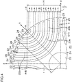
- FIG. 4 is a partially enlarged plan view mainly illustrating one of flux barrier groups in detail.
- a synchronous reluctance motor 1 (hereinafter referred to simply as a “motor 1 ") includes a stator (stationary element) 10 and a rotor (rotary element) 20.
- the stator 10 generates a rotating magnetic field.
- the rotor 20 is provided inside the stator 10, and rotated by the rotating magnetic field.
- the stator 10 includes an annular stator core 11 and stator coils 12.
- the stator core 11 is constituted by stacking a plurality of annular steel plates on each other.
- a plurality of slots 11 a for insertion of the stator coils 12 are provided in the inner peripheral portion of the stator core 11.
- three independent stator coils 12 are wound in the stator core 11, and the stator core 11 has 24 slots 11 a.
- the rotor 20 has four poles (two pairs of poles) in the embodiment.
- the rotor 20 includes a rotor core 21 and a rotor shaft (rotary shaft) 22.
- the rotor shaft 22 penetrates the center portion of the rotor core 21, and is fixed to the rotor core 21.
- the rotor core 21 is constituted by stacking a plurality of circular electromagnetic steel sheets having a hole in the center portion on each other.
- the rotor core 21 is provided with a number of flux barrier groups spaced from each other in the circumferential direction.
- the flux barrier groups are each constituted from a plurality of arcuate flux barriers (in this example, slits (air layers)) 23.
- the number of the flux barrier groups corresponds to the number of poles.
- the flux barriers 23 are disposed in a plurality of layers from the outer peripheral side toward the rotor shaft 22, and are convex toward the rotor shaft 22.
- the rotor core 21 is provided with four flux barrier groups spaced from each other in the circumferential direction.
- the flux barriers 23 in each of the flux barrier groups are provided in seven layers. That is, each of the flux barrier groups is constituted from seven flux barriers 23 with different lengths.
- the flux barriers may be formed from a non-magnetic material such as a resin, rather than being formed as slits.
- regions of the rotor core 21 interposed between two flux barriers 23 that are adjacent to each other in a plan view seen in the direction along the rotor shaft 22 are defined as ribs 24.
- Portions of the rotor core 21 that are close to the outer periphery of the rotor core 21 in the regions of the rotor core 21 interposed between flux barrier groups that are adjacent to each other are defined as connecting portions 25.
- An annular region at the outer peripheral portion of the rotor core 21, including a portion between the outer peripheral edge of the rotor core 21 and the end portions of the flux barriers 23, is defined as a bridge 26.
- An axis that passes through the center, in the circumferential direction, of the flux barriers 23 in the flux barrier group and that extends in the radial direction of the rotor core 21 is defined as a q-axis.
- An axis that passes between flux barrier groups that are adjacent to each other and that extends in the radial direction of the rotor core 21 is defined as a d-axis.
- the flux barriers 23 hinder the flow of magnetic flux. Therefore, magnetic flux from the stator core 11 directed from one of two adjacent q-axes toward the other is not easily conducted. In contrast, magnetic flux directed from one of two adjacent d-axes toward the other is easily conducted by the ribs 24 between the flux barriers 23.
- reluctance torque T is generated from the motor 1.
- Pn is the number of pairs of poles
- Ld is the d-axis inductance
- Lq is the q-axis inductance
- Id is the d-axis current
- Iq is the q-axis current.
- the reluctance torque (output torque) T is increased by increasing the difference (Ld - Lq) between the d-axis inductance Ld and the q-axis inductance Lq.
- the flux barriers 23 are provided to increase the magnetic resistance of the magnetic path in the q-axis direction, and to reduce the magnetic resistance of the magnetic path in the d-axis direction.
- the following design is adopted. That is, the shape of the flux barriers 23 as viewed in plan is set to an appropriate shape.
- the ratio of the width of the ribs 24 to the width of the flux barriers 23 is set to an appropriate value. Further, the ratio of the width of the connecting portions 25 to the width of the ribs 24 is set to an appropriate value.
- the circumferential center points of the flux barrier groups on the outer peripheral edge of the rotor 20 are defined as A, B, C, and D.
- a region of the rotor 20 surrounded by a polygon (in this example, a quadrangle) with vertexes A, B, C, and D as viewed in plan is defined as a polygonal region (in this example, a quadrangular region) 30.
- a side or a line segment that connects between the vertex A and the vertex B of the polygonal region 30 is occasionally represented as A-B.
- a side or a line segment that connects between the vertex B and the vertex C is occasionally represented as B-C.
- a side or a line segment that connects between the vertex C and the vertex D is occasionally represented as C-D.
- a side or a line segment that connects between the vertex D and the vertex A is occasionally represented as D-A.
- the plurality of flux barriers 23 in each of the flux barrier groups are constituted from arcuate portions 23a provided in the polygonal region 30 as viewed in plan, and linear portions 23b.
- the linear portions 23b extend from both end portions of the arcuate portions 23a to a region outside the polygonal region 30.
- the arcuate center of the plurality of arcuate portions 23a in each of the flux barrier groups is set to the circumferential center point A, B, C, or D of the flux barrier group on the outer peripheral edge of the rotor 20.
- the linear portions 23b which extend from the end portions of the arcuate portions 23a extend in a direction that is perpendicular to one of the four sides of the polygonal region 30 that is the closest to the end portions of the arcuate portions 23a as viewed in plan.
- the linear portions 23b which extend from the end portions of the arcuate portions 23a extend in the direction of a tangent to the arcuate portions 23a from the end portions of the arcuate portions 23a.
- the plurality of flux barriers 23 in one of the flux barrier groups mainly illustrated in FIG. 4 are constituted from a plurality of arcuate portions 23a and a plurality of linear portions 23b as viewed in plan.
- the arcuate portions 23a are centered on the point A.
- the linear portions 23b extend perpendicularly to the side A-B from first ends of the arcuate portions 23a on the side of the side A-B, and extend perpendicularly to the side D-A from second ends of the arcuate portions 23a on the side of the side D-A.
- ⁇ is the angle formed by the plane of the planar circuit and the direction of magnetic flux.
- magnetic flux ⁇ is maximized when the angle ⁇ formed by the plane of the planar circuit and the direction of magnetic flux is 90 degrees. If the shape of the plurality of flux barriers 23 in the flux barrier group mainly illustrated in FIG. 4 as viewed in plan is set as described above, magnetic flux that flows in the d-axis direction passes perpendicularly to the cross sections of the ribs 24 along the line segment D-A, and the cross-sectional area of the ribs 24 along the line segment D-A is maximized. Consequently, the magnetism utilization rate is enhanced, and thus the output torque T can be increased.
- the arcuate portions 23a can be formed at a position that is close to the center of the rotor 20 compared to a case where the arcuate center of the flux barriers 23 is set on the q-axis and outward of the outer peripheral edge of the rotor 20. Consequently, the width of the ribs 24 can be increased, and thus the magnetic resistance of the magnetic path in the d-axis direction can be reduced. Consequently, the output torque T can be increased.
- the width of the flux barriers 23 is defined as a [mm]
- the width of the ribs 24 is defined as m [mm]
- the width of the bridge 26 is defined as b [mm]
- the width of the connecting portions 25 is defined as c [mm].
- the length of a section from the point A to the flux barrier 23 that is the closest to the point A on the line segment D-A is defined as d [mm].
- the distance from the point A to the midpoint of the line segment D-A on the line segment D-A is defined as H [mm].
- b is preferably 0.5 mm or less.
- d is preferably 2 1/2 ⁇ b or more.
- c is preferably 0.5 mm or more and 3 mm or less.
- Table 1 indicates the result of simulating the output torque with respect to the width (rib width) m of the ribs 24 and the result of simulating the torque ripple with respect to the width m of the ribs 24 for a case where the sum of the width m of the ribs 24 and the width (slit width) a of the flux barriers 23 is constant.
- the sum of the width m of the ribs 24 and the width a of the flux barriers 23 is determined as 2.2 mm to 2.5 mm.
- Table 1 also indicates the values of the width a of the flux barriers 23 corresponding to the width m of the ribs 24, and a ratio m/a of the width m of the ribs 24 to the width a of the flux barriers 23 corresponding to the width m of the ribs 24.
- FIG. 5A is a graph indicating the result of simulating the output torque with respect to the width m of the ribs 24, among the simulation results indicated in Table 1.
- FIG. 5B is a graph indicating the result of simulating the torque ripple with respect to the width m of the ribs 24, among the simulation results indicated in Table 1.
- the output torque is maximized when the width m of the ribs 24 is 1.5 mm to 1.7 mm (the width a of the flux barriers 23 is 1.0 mm to 0.8 mm). That is, the output torque is maximized when the ratio m/a of the width m of the ribs 24 to the width a of the flux barriers 23 is 1.50 to 2.13.
- the width m of the ribs 24 When the width m of the ribs 24 is in the range of 1.5 mm or less, the amount of magnetic flux that passes through the ribs 24 is increased as the width m of the ribs 24 is increased. Therefore, it is considered that the output torque is increased as the width m of the ribs 24 is increased when the width m of the ribs 24 is in this range (1.5 mm or less).
- the width m of the ribs 24 is increased, the width a of the flux barriers 23 is reduced.
- the width m of the ribs 24 is more than 1.7 mm, the width a of the flux barriers 23 is too small. Therefore, it is considered that much magnetic flux leaks in the q-axis direction. Therefore, the output torque is reduced as the width m of the ribs 24 is increased to be more than 1.7 mm.
- the torque ripple is minimized when the width m of the ribs 24 is about 1.7 mm (the width a of the flux barriers 23 is about 0.8 mm). That is, the torque ripple is minimized when the ratio m/a of the width m of the ribs 24 to the width a of the flux barriers 23 is about 2.13.
- the width m of the ribs 24 is preferably 1.5 or more and 1.9 or less, more preferably 1.6 or more and 1.8 or less.
- the ratio m/a of the width m of the ribs 24 to the width a of the flux barriers 23 is preferably 1.50 or more and 4.75 or less, more preferably 1.78 or more and 3.00 or less.
- Table 2 indicates the result of simulating the torque ripple with respect to a ratio c/m of the width (connecting portion width) c of the connecting portions 25 to the width (rib width) m of the ribs 24 at the time when the width m of the ribs 24 and the width (slit width) a of the flux barriers 23 are constant and the width c of the connecting portions 25 and the length (section length d) of the section d are varied such that the distance H is constant.
- the width m of the ribs 24 is determined as 1.70 mm
- the width a of the flux barriers 23 is determined as 0.80 mm
- the distance H is determined as 17.50 mm.
- Table 2 indicates half (c/2) the width c of the connecting portions 25 in place of the width c of the connecting portions 25. It is assumed that d, a, m, c and H satisfy the formula (3).
- [Table 2] c/m Slit width a [mm] Half (c/2) of connecting portion width c [mm] Rib width m [mm] Distance H [mm] Torque ripple [%] 0.29 0.80 0.25 1.70 17.50 14.72 0.35 0.80 0.30 1.70 17.50 14.51 0.41 0.80 0.35 1.70 17.50 13.80 0.47 0.80 0.40 1.70 17.50 13.12 0.53 0.80 0.45 1.70 17.50 11.97 0.59 0.80 0.50 1.70 17.50 10.74 0.65 0.80 0.55 1.70 17.50 9.86 0.71 0.80 0.60 1.70 17.50 8.73 0.76 0.80 0.65 1.70 17.50 8.88 0.82 0.80 0.70 1.70 17.50 9.00 0.88 0.80 0.75 1.70 17.50 8.77 0.94 0.80 0.80 1.70 17.50 8.38 1.00 0.80 0.85 1.
- FIG. 6 is a graph indicating the simulation results indicated in Table 2.
- the torque ripple is less than 12% when the ratio of the width c of the connecting portions 25 to the width m of the ribs 24 is equal to or more than 0.53.
- the ratio of the width c of the connecting portions 25 to the width m of the ribs 24 is 1.18 at highest.
- the torque ripple is less than 12% even in the case where the ratio of the width c of the connecting portions 25 to the width m of the ribs 24 is 1.18.
- Table 3 indicates the result of simulating the torque ripple with respect to the ratio c/m of the width (connecting portion width) c of the connecting portions 25 to the width (rib width) m of the ribs 24 at the time when the width m of the ribs 24 and the length (section length d) of the section d are constant and the width c of the connecting portions 25 and the width (slit width) a of the flux barriers 23 are varied such that the distance H is constant.
- the width m of the ribs 24 is determined as 1.70 mm
- the length of the section d is determined as 0.7 mm
- the distance H is determined as 17.50 mm.
- Table 3 indicates half (c/2) the width c of the connecting portions 25 in place of the width c of the connecting portions 25. It is assumed that d, a, m, c and H satisfy the formula (3).
- [Table 3] c/m Slit width a [mm] Half (c/2) of connecting portion width c [mm] Rib width m [mm] Distance H [mm] Torque ripple [%] 0.5 0.82 0.85 1.70 17.50 8.88 0.6 0.80 1.02 1.70 17.50 8.29 0.7 0.77 1.19 1.70 17.50 9.68 0.8 0.75 1.36 1.70 17.50 10.97 0.9 0.72 1.53 1.70 17.50 13.69 1 0.70 1.70 1.70 17.50 15.80 1.1 0.68 1.87 1.70 17.50 15.76 1.2 0.65 2.04 1.70 17.50 13.98 1.3 0.63 2.21 1.70 17.50 13.74 1.4 0.60 2.38 1.70 17.50 17.14 1.5 0.58 2.55 1.70 17.50 20.86 1.6 0.55 2.72 1.70 17.50 23.36 1.7 0.53 2.89 1.
- FIG. 7 is a graph indicating the simulation results indicated in Table 3.
- the torque ripple is less than 12% when the ratio of the width c of the connecting portions 25 to the width m of the ribs 24 is 0.5 or more and 0.8 or less.
- Table 4 indicates the result of simulating the torque ripple with respect to the ratio c/m of the width (connecting portion width) c of the connecting portions 25 to the width (rib width) m of the ribs 24 at the time when the width (slit width) a of the flux barriers 23 and the length (section length d) of the section d are constant and the width c of the connecting portions 25 and the width m of the ribs 24 are varied such that the distance H is constant.
- the width a of the flux barriers 23 is determined as 0.8 mm
- the length of the section d is determined as 0.7 mm
- the distance H is determined as 17.50 mm. It is assumed that d, a, m, c and H satisfy the formula (3).
- FIG. 8 is a graph indicating the simulation results indicated in Table 4.
- the torque ripple is less than 12% when the ratio of the width c of the connecting portions 25 to the width m of the ribs 24 is 0.5 or more and 1.6 or less. From the simulation results of Tables 2, 3, and 4, it is found that the torque ripple is less than 12% when the ratio of the width c of the connecting portions 25 to the width m of the ribs 24 is 0.53 or more and 0.8 or less. For this reason, it is found that, in order to suppress the torque ripple to be low, the ratio of the width c of the connecting portions 25 to the width m of the ribs 24 is 0.53 or more and 0.8 or less.
- the present invention may be implemented in other embodiments.
- the rotor 20 has four poles (two pairs of poles) in the embodiment discussed above.
- the rotor 20 may have a different number of poles such as six poles (three pairs of poles) or eight poles (four pairs of poles).
- the flux barriers 23 are provided in seven layers.
- the flux barriers 23 may be provided in a different number of layers such as five layers, six layers, eight layers, or nine layers.
- the values of the radius r of the rotor 20, the width c of the connecting portions 25, the width m of the ribs 24, the width a of the flux barriers 23, and the width b of the bridge 26 are not limited to those indicated in the embodiment discussed above.
- the present invention can be applied to a synchronous motor for use in electric power steering systems, for example. However, the present invention can also be applied to a synchronous motor for use in systems other than electric power steering systems.
Landscapes
- Engineering & Computer Science (AREA)
- Power Engineering (AREA)
- Synchronous Machinery (AREA)
- Iron Core Of Rotating Electric Machines (AREA)
Abstract
Description
- The present invention relates to a synchronous reluctance motor for use in an electric power steering system, for example.
- There is known a reluctance motor in which a rotor is rotated utilizing only reluctance torque generated by variations in electromagnetic energy with respect to a position. The reluctance motor includes a switched reluctance motor (SRM) and a synchronous reluctance motor (SynRM). In the switched reluctance motor, the stator and the rotor have magnetic saliency. In the synchronous reluctance motor, the stator is structured in the same manner as that of a brushless motor.
- In the synchronous reluctance motor, only the rotor, among the stator and the rotor, has magnetic saliency. The synchronous reluctance motor has a salient direction (hereinafter referred to as a "d-axis direction") in which magnetic flux flows easily, and a non-salient direction (hereinafter referred to as a "q-axis direction") in which magnetic flux does not flow easily, in accordance with the magnetic saliency of the rotor. Therefore, reluctance torque is generated by the difference between an inductance in the d-axis direction (hereinafter referred to as a "d-axis inductance") and an inductance in the q-axis direction (hereinafter referred to as a "q-axis inductance"), and the rotor is rotated by the reluctance torque (see Japanese Patent Application Publication No.
11-289730 JP 11-289730 A - In the synchronous reluctance motor, the rotor is rotated utilizing only the reluctance torque, rather than using permanent magnets. Therefore, the synchronous reluctance motor generates small output torque compared to a motor that uses permanent magnets, and it is necessary to increase the output torque, even if only slightly.
- It is an object of the present invention to provide a synchronous reluctance motor capable of generating large output torque with little torque ripple.
- An aspect of the present invention provides a synchronous reluctance motor including a stator and a rotor, the rotor being provided with a number of flux barrier groups each constituted from a plurality of arcuate flux barriers and spaced from each other in a circumferential direction, the number of the flux barrier groups being equal to that of poles, and the flux barriers being disposed in a plurality of layers from an outer periphery toward a center and being convex toward the center. When a region surrounded by a polygon with vertexes constituted by circumferential center points of the flux barrier groups on an outer peripheral edge of the rotor as viewed in plan in a direction along a rotary shaft of the rotor is defined as a polygonal region, the plurality of flux barriers in each of the flux barrier groups include arcuate portions formed in the polygonal region. An arcuate center of the arcuate portions in each of the flux barrier groups is set to the circumferential center point of the flux barrier group on the outer peripheral edge of the rotor. When regions of the rotor interposed between two flux barriers that are adjacent to each other in the flux barrier groups are defined as ribs, and portions of the rotor that are close to the outer periphery of the rotor in the regions of the rotor interposed between flux barrier groups that are adjacent to each other are defined as connecting portions, a ratio of a width of the connecting portions to a width of the ribs is 0.53 or more and 0.8 or less.
- The foregoing and further features and advantages of the invention will become apparent from the following description of example embodiments with reference to the accompanying drawings, wherein like numerals are used to represent like elements and wherein:
-
FIG. 1 is a cross-sectional view illustrating the configuration of a synchronous reluctance motor according to an embodiment of the present invention; -
FIG. 2 is an enlarged plan view illustrating a rotor of the synchronous reluctance motor ofFIG. 1 ; -
FIG. 3 is a sectional view taken along the line III-III ofFIG. 2 ; -
FIG. 4 is a partially enlarged plan view mainly illustrating one of flux barrier groups in detail; -
FIG. 5A is a graph illustrating the result of simulating output torque with respect to a width m of ribs for a case where the sum of the width m of the ribs and a width a of flux barriers is constant; -
FIG. 5B is a graph illustrating the result of simulating torque ripple with respect to the width m of the ribs for a case where the sum of the width m of the ribs and the width a of the flux barriers is constant; -
FIG. 6 is a graph illustrating the result of simulating torque ripple with respect to a ratio c/m of a width c of connecting portions to the width m of the ribs at the time when the width m of the ribs and the width a of the flux barriers are constant and the width c of the connecting portions and the length of a section d are varied such that a distance H is constant; -
FIG. 7 is a graph illustrating the result of simulating torque ripple with respect to the ratio c/m of the width c of the connecting portions to the width m of the ribs at the time when the width m of the ribs and the length of the section d are constant and the width c of the connecting portions and the width a of the flux barriers are varied such that the distance H is constant; and -
FIG. 8 is a graph illustrating the result of simulating torque ripple with respect to the ratio c/m of the width c of the connecting portions to the width m of the ribs at the time when the width a of the flux barriers and the length of the section d are constant and the width c of the connecting portions and the width m of the ribs are varied such that the distance H is constant. - An embodiment of the present invention will be described in detail below with reference to the accompanying drawings.
FIG. 1 is a cross-sectional view illustrating the configuration of a synchronous reluctance motor according to an embodiment of the present invention.FIG. 2 is an enlarged plan view illustrating a rotor of the synchronous reluctance motor ofFIG. 1 .FIG. 3 is a sectional view taken along the line III-III ofFIG. 2 .FIG. 4 is a partially enlarged plan view mainly illustrating one of flux barrier groups in detail. - With reference to
FIG. 1 , a synchronous reluctance motor 1 (hereinafter referred to simply as a "motor 1 ") includes a stator (stationary element) 10 and a rotor (rotary element) 20. Thestator 10 generates a rotating magnetic field. Therotor 20 is provided inside thestator 10, and rotated by the rotating magnetic field. Thestator 10 includes anannular stator core 11 andstator coils 12. Thestator core 11 is constituted by stacking a plurality of annular steel plates on each other. A plurality ofslots 11 a for insertion of thestator coils 12 are provided in the inner peripheral portion of thestator core 11. In the embodiment, threeindependent stator coils 12 are wound in thestator core 11, and thestator core 11 has 24slots 11 a. - With reference to
FIGS. 1 to 4 , therotor 20 has four poles (two pairs of poles) in the embodiment. Therotor 20 includes arotor core 21 and a rotor shaft (rotary shaft) 22. Therotor shaft 22 penetrates the center portion of therotor core 21, and is fixed to therotor core 21. Therotor core 21 is constituted by stacking a plurality of circular electromagnetic steel sheets having a hole in the center portion on each other. Therotor core 21 is provided with a number of flux barrier groups spaced from each other in the circumferential direction. The flux barrier groups are each constituted from a plurality of arcuate flux barriers (in this example, slits (air layers)) 23. The number of the flux barrier groups corresponds to the number of poles. Theflux barriers 23 are disposed in a plurality of layers from the outer peripheral side toward therotor shaft 22, and are convex toward therotor shaft 22. In this example, therotor core 21 is provided with four flux barrier groups spaced from each other in the circumferential direction. Theflux barriers 23 in each of the flux barrier groups are provided in seven layers. That is, each of the flux barrier groups is constituted from sevenflux barriers 23 with different lengths. The flux barriers may be formed from a non-magnetic material such as a resin, rather than being formed as slits. - With reference to
FIGS. 2 and4 , regions of therotor core 21 interposed between twoflux barriers 23 that are adjacent to each other in the same flux barrier group in a plan view seen in the direction along therotor shaft 22 are defined asribs 24. Portions of therotor core 21 that are close to the outer periphery of therotor core 21 in the regions of therotor core 21 interposed between flux barrier groups that are adjacent to each other are defined as connectingportions 25. An annular region at the outer peripheral portion of therotor core 21, including a portion between the outer peripheral edge of therotor core 21 and the end portions of theflux barriers 23, is defined as abridge 26. - An axis that passes through the center, in the circumferential direction, of the
flux barriers 23 in the flux barrier group and that extends in the radial direction of therotor core 21 is defined as a q-axis. An axis that passes between flux barrier groups that are adjacent to each other and that extends in the radial direction of therotor core 21 is defined as a d-axis. Theflux barriers 23 hinder the flow of magnetic flux. Therefore, magnetic flux from thestator core 11 directed from one of two adjacent q-axes toward the other is not easily conducted. In contrast, magnetic flux directed from one of two adjacent d-axes toward the other is easily conducted by theribs 24 between theflux barriers 23. - When a rotating magnetic field is applied to the
rotor 20 by thestator 10, reluctance torque T is generated from themotor 1. The reluctance torque T is represented by the following formula (1):
- In the formula (1), Pn is the number of pairs of poles, Ld is the d-axis inductance, Lq is the q-axis inductance, Id is the d-axis current, and Iq is the q-axis current.
- Thus, the reluctance torque (output torque) T is increased by increasing the difference (Ld - Lq) between the d-axis inductance Ld and the q-axis inductance Lq. In the embodiment, in order to increase the difference (Ld - Lq), the
flux barriers 23 are provided to increase the magnetic resistance of the magnetic path in the q-axis direction, and to reduce the magnetic resistance of the magnetic path in the d-axis direction. In the embodiment, further, in order to increase the reluctance torque T (motor output) while reducing torque ripple, the following design is adopted. That is, the shape of theflux barriers 23 as viewed in plan is set to an appropriate shape. In addition, the ratio of the width of theribs 24 to the width of theflux barriers 23 is set to an appropriate value. Further, the ratio of the width of the connectingportions 25 to the width of theribs 24 is set to an appropriate value. Such features will be described in detail below. - First, the shape of the
flux barriers 23 as viewed in plan will be described with reference toFIGS. 2 and4 . The circumferential center points of the flux barrier groups on the outer peripheral edge of therotor 20 are defined as A, B, C, and D. A region of therotor 20 surrounded by a polygon (in this example, a quadrangle) with vertexes A, B, C, and D as viewed in plan is defined as a polygonal region (in this example, a quadrangular region) 30. A side or a line segment that connects between the vertex A and the vertex B of thepolygonal region 30 is occasionally represented as A-B. A side or a line segment that connects between the vertex B and the vertex C is occasionally represented as B-C. A side or a line segment that connects between the vertex C and the vertex D is occasionally represented as C-D. A side or a line segment that connects between the vertex D and the vertex A is occasionally represented as D-A. - The plurality of
flux barriers 23 in each of the flux barrier groups are constituted fromarcuate portions 23a provided in thepolygonal region 30 as viewed in plan, andlinear portions 23b. Thelinear portions 23b extend from both end portions of thearcuate portions 23a to a region outside thepolygonal region 30. The arcuate center of the plurality ofarcuate portions 23a in each of the flux barrier groups is set to the circumferential center point A, B, C, or D of the flux barrier group on the outer peripheral edge of therotor 20. Thelinear portions 23b which extend from the end portions of thearcuate portions 23a extend in a direction that is perpendicular to one of the four sides of thepolygonal region 30 that is the closest to the end portions of thearcuate portions 23a as viewed in plan. In other words, thelinear portions 23b which extend from the end portions of thearcuate portions 23a extend in the direction of a tangent to thearcuate portions 23a from the end portions of thearcuate portions 23a. - For example, the plurality of
flux barriers 23 in one of the flux barrier groups mainly illustrated inFIG. 4 are constituted from a plurality ofarcuate portions 23a and a plurality oflinear portions 23b as viewed in plan. Thearcuate portions 23a are centered on the point A. Thelinear portions 23b extend perpendicularly to the side A-B from first ends of thearcuate portions 23a on the side of the side A-B, and extend perpendicularly to the side D-A from second ends of thearcuate portions 23a on the side of the side D-A. - The reason that the shape of the plurality of
flux barriers 23 in each of the flux barrier groups as viewed in plan is set as described above will be described using the flux barrier group mainly illustrated inFIG. 4 as an example. In general, when a planar circuit with an area of S is placed in a magnetic field with a magnetic flux density of B [wb], magnetic flux φ which penetrates the planar circuit with an area of S is represented by the following formula (2):
- θ is the angle formed by the plane of the planar circuit and the direction of magnetic flux.
- From the formula (2), it is found that magnetic flux φ is maximized when the angle θ formed by the plane of the planar circuit and the direction of magnetic flux is 90 degrees. If the shape of the plurality of
flux barriers 23 in the flux barrier group mainly illustrated inFIG. 4 as viewed in plan is set as described above, magnetic flux that flows in the d-axis direction passes perpendicularly to the cross sections of theribs 24 along the line segment D-A, and the cross-sectional area of theribs 24 along the line segment D-A is maximized. Consequently, the magnetism utilization rate is enhanced, and thus the output torque T can be increased. - The
arcuate portions 23a can be formed at a position that is close to the center of therotor 20 compared to a case where the arcuate center of theflux barriers 23 is set on the q-axis and outward of the outer peripheral edge of therotor 20. Consequently, the width of theribs 24 can be increased, and thus the magnetic resistance of the magnetic path in the d-axis direction can be reduced. Consequently, the output torque T can be increased. - Next, the ratio of the width of the
ribs 24 to the width of theflux barriers 23 will be described. As illustrated inFIG. 4 , the width of theflux barriers 23 is defined as a [mm], the width of theribs 24 is defined as m [mm], the width of thebridge 26 is defined as b [mm], and the width of the connectingportions 25 is defined as c [mm]. The length of a section from the point A to theflux barrier 23 that is the closest to the point A on the line segment D-A is defined as d [mm]. The distance from the point A to the midpoint of the line segment D-A on the line segment D-A is defined as H [mm]. When the radius of therotor 20 is defined as r [mm], H = r/21/2 is satisfied. - As seen from
FIG. 4 , the following formula (3) is satisfied:
In the embodiment, r, c, d, m, and a are set as follows, for example.
r = 24.8 mm, c = 2 mm, b = 0.5 mm, d = 2 1/2·b, m = 1.7 mm, and a = 0.8 mm. - Table 1 indicates the result of simulating the output torque with respect to the width (rib width) m of the
ribs 24 and the result of simulating the torque ripple with respect to the width m of theribs 24 for a case where the sum of the width m of theribs 24 and the width (slit width) a of theflux barriers 23 is constant. Here, the sum of the width m of theribs 24 and the width a of theflux barriers 23 is determined as 2.2 mm to 2.5 mm. Table 1 also indicates the values of the width a of theflux barriers 23 corresponding to the width m of theribs 24, and a ratio m/a of the width m of theribs 24 to the width a of theflux barriers 23 corresponding to the width m of theribs 24.[Table 1] Rib width m [mm] Slit width a [mm] m/a Torque [Nm] Torque ripple [%] 0.8 1.7 0.47 3.30 34.0 0.9 1.6 0.56 3.58 31.5 1 1.5 0.67 3.82 28.5 1.1 1.4 0.79 4.05 23.5 1.25 1.25 1.00 4.32 17.1 1.3 1.2 1.08 4.40 15.6 1.4 1.1 1.27 4.50 12.3 1.5 1 1.50 4.59 9.30 1.7 0.8 2.13 4.59 6.50 1.8 0.6 3.00 4.52 8.40 1.9 0.4 4.75 4.41 10.1 2 0.2 10.00 4.23 12.1 -
FIG. 5A is a graph indicating the result of simulating the output torque with respect to the width m of theribs 24, among the simulation results indicated in Table 1.FIG. 5B is a graph indicating the result of simulating the torque ripple with respect to the width m of theribs 24, among the simulation results indicated in Table 1. As indicated in Table 1 andFIG. 5A , the output torque is maximized when the width m of theribs 24 is 1.5 mm to 1.7 mm (the width a of theflux barriers 23 is 1.0 mm to 0.8 mm). That is, the output torque is maximized when the ratio m/a of the width m of theribs 24 to the width a of theflux barriers 23 is 1.50 to 2.13. When the width m of theribs 24 is in the range of 1.5 mm or less, the amount of magnetic flux that passes through theribs 24 is increased as the width m of theribs 24 is increased. Therefore, it is considered that the output torque is increased as the width m of theribs 24 is increased when the width m of theribs 24 is in this range (1.5 mm or less). When the width m of theribs 24 is increased, the width a of theflux barriers 23 is reduced. When the width m of theribs 24 is more than 1.7 mm, the width a of theflux barriers 23 is too small. Therefore, it is considered that much magnetic flux leaks in the q-axis direction. Therefore, the output torque is reduced as the width m of theribs 24 is increased to be more than 1.7 mm. - As indicated in Table 1 and
FIG. 5B , the torque ripple is minimized when the width m of theribs 24 is about 1.7 mm (the width a of theflux barriers 23 is about 0.8 mm). That is, the torque ripple is minimized when the ratio m/a of the width m of theribs 24 to the width a of theflux barriers 23 is about 2.13. For this reason, it is found that, in order to increase the output torque while suppressing the torque ripple, the width m of theribs 24 is preferably 1.5 or more and 1.9 or less, more preferably 1.6 or more and 1.8 or less. In other words, it is found that, in order to increase the output torque while suppressing the torque ripple, the ratio m/a of the width m of theribs 24 to the width a of theflux barriers 23 is preferably 1.50 or more and 4.75 or less, more preferably 1.78 or more and 3.00 or less. - Table 2 indicates the result of simulating the torque ripple with respect to a ratio c/m of the width (connecting portion width) c of the connecting
portions 25 to the width (rib width) m of theribs 24 at the time when the width m of theribs 24 and the width (slit width) a of theflux barriers 23 are constant and the width c of the connectingportions 25 and the length (section length d) of the section d are varied such that the distance H is constant. Here, the width m of theribs 24 is determined as 1.70 mm, the width a of theflux barriers 23 is determined as 0.80 mm, and the distance H is determined as 17.50 mm. Table 2 indicates half (c/2) the width c of the connectingportions 25 in place of the width c of the connectingportions 25. It is assumed that d, a, m, c and H satisfy the formula (3).[Table 2] c/m Slit width a [mm] Half (c/2) of connecting portion width c [mm] Rib width m [mm] Distance H [mm] Torque ripple [%] 0.29 0.80 0.25 1.70 17.50 14.72 0.35 0.80 0.30 1.70 17.50 14.51 0.41 0.80 0.35 1.70 17.50 13.80 0.47 0.80 0.40 1.70 17.50 13.12 0.53 0.80 0.45 1.70 17.50 11.97 0.59 0.80 0.50 1.70 17.50 10.74 0.65 0.80 0.55 1.70 17.50 9.86 0.71 0.80 0.60 1.70 17.50 8.73 0.76 0.80 0.65 1.70 17.50 8.88 0.82 0.80 0.70 1.70 17.50 9.00 0.88 0.80 0.75 1.70 17.50 8.77 0.94 0.80 0.80 1.70 17.50 8.38 1.00 0.80 0.85 1.70 17.50 8.23 1.06 0.80 0.90 1.70 17.50 8.25 1.12 0.80 0.95 1.70 17.50 8.22 1.18 0.80 1.00 1.70 17.50 8.23 -
FIG. 6 is a graph indicating the simulation results indicated in Table 2. As indicated in Table 2 andFIG. 6 , the torque ripple is less than 12% when the ratio of the width c of the connectingportions 25 to the width m of theribs 24 is equal to or more than 0.53. In order to meet the formula (3), the ratio of the width c of the connectingportions 25 to the width m of theribs 24 is 1.18 at highest. However, the torque ripple is less than 12% even in the case where the ratio of the width c of the connectingportions 25 to the width m of theribs 24 is 1.18. - Table 3 indicates the result of simulating the torque ripple with respect to the ratio c/m of the width (connecting portion width) c of the connecting
portions 25 to the width (rib width) m of theribs 24 at the time when the width m of theribs 24 and the length (section length d) of the section d are constant and the width c of the connectingportions 25 and the width (slit width) a of theflux barriers 23 are varied such that the distance H is constant. Here, the width m of theribs 24 is determined as 1.70 mm, the length of the section d is determined as 0.7 mm, and the distance H is determined as 17.50 mm. Table 3 indicates half (c/2) the width c of the connectingportions 25 in place of the width c of the connectingportions 25. It is assumed that d, a, m, c and H satisfy the formula (3).[Table 3] c/m Slit width a [mm] Half (c/2) of connecting portion width c [mm] Rib width m [mm] Distance H [mm] Torque ripple [%] 0.5 0.82 0.85 1.70 17.50 8.88 0.6 0.80 1.02 1.70 17.50 8.29 0.7 0.77 1.19 1.70 17.50 9.68 0.8 0.75 1.36 1.70 17.50 10.97 0.9 0.72 1.53 1.70 17.50 13.69 1 0.70 1.70 1.70 17.50 15.80 1.1 0.68 1.87 1.70 17.50 15.76 1.2 0.65 2.04 1.70 17.50 13.98 1.3 0.63 2.21 1.70 17.50 13.74 1.4 0.60 2.38 1.70 17.50 17.14 1.5 0.58 2.55 1.70 17.50 20.86 1.6 0.55 2.72 1.70 17.50 23.36 1.7 0.53 2.89 1.70 17.50 24.99 1.8 0.51 3.06 1.70 17.50 25.24 1.9 0.48 3.23 1.70 17.50 24.18 2 0.46 3.40 1.70 17.50 22.37 2.1 0.43 3.57 1.70 17.50 19.57 2.2 0.41 3.74 1.70 17.50 22.21 2.3 0.38 3.91 1.70 17.50 26.09 2.4 0.36 4.08 1.70 17.50 28.59 2.5 0.34 4.25 1.70 17.50 31.84 2.6 0.31 4.42 1.70 17.50 33.36 2.7 0.29 4.59 1.70 17.50 32.15 2.8 0.26 4.76 1.70 17.50 28.22 2.9 0.24 4.93 1.70 17.50 22.02 3 0.21 5.10 1.70 17.50 19.26 3.1 0.19 5.27 1.70 17.50 23.74 3.2 0.17 5.44 1.70 17.50 28.39 3.3 0.14 5.61 1.70 17.50 31.71 3.4 0.12 5.78 1.70 17.50 35.23 3.5 0.09 5.95 1.70 17.50 35.96 -
FIG. 7 is a graph indicating the simulation results indicated in Table 3. As indicated in Table 3 andFIG. 7 , the torque ripple is less than 12% when the ratio of the width c of the connectingportions 25 to the width m of theribs 24 is 0.5 or more and 0.8 or less. Table 4 indicates the result of simulating the torque ripple with respect to the ratio c/m of the width (connecting portion width) c of the connectingportions 25 to the width (rib width) m of theribs 24 at the time when the width (slit width) a of theflux barriers 23 and the length (section length d) of the section d are constant and the width c of the connectingportions 25 and the width m of theribs 24 are varied such that the distance H is constant. Here, the width a of theflux barriers 23 is determined as 0.8 mm, the length of the section d is determined as 0.7 mm, and the distance H is determined as 17.50 mm. It is assumed that d, a, m, c and H satisfy the formula (3).[Table 4] c/m Slit width a [mm] Half (c/2) of connecting portion width c [mm] Rib width m [mm] Distance H [mm] Torque ripple [%] 0.5 0.8 0.45 1.79 17.50 9.59 0.6 0.8 0.53 1.78 17.50 9.44 0.7 0.8 0.62 1.76 17.50 9.77 0.8 0.8 0.70 1.75 17.50 9.81 0.9 0.8 0.78 1.74 17.50 9.48 1 0.8 0.86 1.72 17.50 8.78 1.1 0.8 0.94 1.71 17.50 8.02 1.2 0.8 1.02 1.70 17.50 8.29 1.3 0.8 1.09 1.68 17.50 8.85 1.4 0.8 1.17 1.67 17.50 9.78 1.5 0.8 1.24 1.66 17.50 10.27 1.6 0.8 1.32 1.65 17.50 11.43 1.7 0.8 1.39 1.64 17.50 12.34 1.8 0.8 1.46 1.62 17.50 13.45 1.9 0.8 1.53 1.61 17.50 14.08 2 0.8 1.60 1.60 17.50 14.61 2.1 0.8 1.67 1.59 17.50 15.20 2.2 0.8 1.74 1.58 17.50 15.37 2.3 0.8 1.80 1.57 17.50 15.39 2.4 0.8 1.87 1.56 17.50 15.01 2.5 0.8 1.93 1.54 17.50 14.66 2.6 0.8 1.99 1.53 17.50 13.93 2.7 0.8 2.06 1.52 17.50 13.88 2.8 0.8 2.12 1.51 17.50 14.67 2.9 0.8 2.18 1.50 17.50 15.49 3 0.8 2.24 1.49 17.50 16.44 3.1 0.8 2.30 1.48 17.50 17.48 3.2 0.8 2.36 1.47 17.50 18.73 3.3 0.8 2.42 1.46 17.50 20.23 3.4 0.8 2.47 1.45 17.50 21.69 3.5 0.8 2.53 1.45 17.50 22.91 3.6 0.8 2.58 1.44 17.50 23.74 3.7 0.8 2.64 1.43 17.50 24.53 3.8 0.8 2.69 1.42 17.50 25.29 3.9 0.8 2.75 1.41 17.50 25.67 4 0.8 2.80 1.40 17.50 25.99 4.1 0.8 2.85 1.39 17.50 26.30 4.2 0.8 2.90 1.38 17.50 26.31 4.3 0.8 2.95 1.37 17.50 26.01 4.4 0.8 3.00 1.37 17.50 25.96 4.5 0.8 3.05 1.36 17.50 25.66 4.6 0.8 3.10 1.35 17.50 25.09 4.7 0.8 3.15 1.34 17.50 24.69 4.8 0.8 3.20 1.33 17.50 24.26 4.9 0.8 3.25 1.33 17.50 23.18 5 0.8 3.29 1.32 17.50 22.31 -
FIG. 8 is a graph indicating the simulation results indicated in Table 4. As indicated in Table 4 andFIG. 8 , the torque ripple is less than 12% when the ratio of the width c of the connectingportions 25 to the width m of theribs 24 is 0.5 or more and 1.6 or less. From the simulation results of Tables 2, 3, and 4, it is found that the torque ripple is less than 12% when the ratio of the width c of the connectingportions 25 to the width m of theribs 24 is 0.53 or more and 0.8 or less. For this reason, it is found that, in order to suppress the torque ripple to be low, the ratio of the width c of the connectingportions 25 to the width m of theribs 24 is 0.53 or more and 0.8 or less. - While an embodiment of the present invention has been described above, the present invention may be implemented in other embodiments. For example, the
rotor 20 has four poles (two pairs of poles) in the embodiment discussed above. However, therotor 20 may have a different number of poles such as six poles (three pairs of poles) or eight poles (four pairs of poles). In the embodiment discussed above, theflux barriers 23 are provided in seven layers. However, theflux barriers 23 may be provided in a different number of layers such as five layers, six layers, eight layers, or nine layers. - The values of the radius r of the
rotor 20, the width c of the connectingportions 25, the width m of theribs 24, the width a of theflux barriers 23, and the width b of thebridge 26 are not limited to those indicated in the embodiment discussed above. The present invention can be applied to a synchronous motor for use in electric power steering systems, for example. However, the present invention can also be applied to a synchronous motor for use in systems other than electric power steering systems. - Besides, a variety of design changes may be made without departing from the scope described in the claims.
Claims (4)
- A synchronous reluctance motor comprising:a stator; anda rotor, the rotor being provided with a number of flux barrier groups each constituted from a plurality of arcuate flux barriers and spaced from each other in a circumferential direction, the number of the flux barrier groups being equal to that of poles, and the flux barriers being disposed in a plurality of layers from an outer periphery toward a center and being convex toward the center, whereinwhen a region surrounded by a polygon with vertexes constituted by circumferential center points of the flux barrier groups on an outer peripheral edge of the rotor as viewed in plan in a direction along a rotary shaft of the rotor is defined as a polygonal region, the plurality of flux barriers in each of the flux barrier groups include arcuate portions formed in the polygonal region,an arcuate center of the arcuate portions in each of the flux barrier groups is set to the circumferential center point of the flux barrier group on the outer peripheral edge of the rotor, andwhen regions of the rotor interposed between two flux barriers that are adjacent to each other in the flux barrier groups are defined as ribs, and portions of the rotor that are close to the outer periphery of the rotor in the regions of the rotor interposed between flux barrier groups that are adjacent to each other are defined as connecting portions, a ratio of a width of the connecting portions to a width of the ribs is 0.53 or more and 0.8 or less.
- The synchronous reluctance motor according to claim 1, wherein
a ratio of the width of the ribs to a width of the flux barriers is 1.50 or more and 4.75 or less. - The synchronous reluctance motor according to claim 1 or 2, wherein
the width of the connecting portions is 0.5 mm or more and 3.0 mm or less. - The synchronous reluctance motor according to any one of claims 1 to 3, wherein the plurality of flux barriers in each of the flux barrier groups are constituted from the arcuate portions formed in the polygonal region as viewed in plan, and linear portions that extend in a direction that is perpendicular to a side of the polygonal region from both end portions of the arcuate portions to a region outside the polygonal region.
Applications Claiming Priority (1)
| Application Number | Priority Date | Filing Date | Title |
|---|---|---|---|
| JP2016066425A JP2017184386A (en) | 2016-03-29 | 2016-03-29 | Synchronous reluctance motor |
Publications (2)
| Publication Number | Publication Date |
|---|---|
| EP3226385A1 true EP3226385A1 (en) | 2017-10-04 |
| EP3226385B1 EP3226385B1 (en) | 2019-01-02 |
Family
ID=58401495
Family Applications (1)
| Application Number | Title | Priority Date | Filing Date |
|---|---|---|---|
| EP17162384.6A Not-in-force EP3226385B1 (en) | 2016-03-29 | 2017-03-22 | Synchronous reluctance motor |
Country Status (4)
| Country | Link |
|---|---|
| US (1) | US10284063B2 (en) |
| EP (1) | EP3226385B1 (en) |
| JP (1) | JP2017184386A (en) |
| CN (1) | CN107240999A (en) |
Families Citing this family (9)
| Publication number | Priority date | Publication date | Assignee | Title |
|---|---|---|---|---|
| JP6877944B2 (en) * | 2016-10-11 | 2021-05-26 | 東芝産業機器システム株式会社 | Synchronous reluctance type rotary electric machine |
| CN108736601B (en) * | 2017-04-17 | 2020-10-27 | 日本电产株式会社 | Rotor, motor having the same, and method for reducing torque chain wave of rotor |
| US10666097B2 (en) * | 2017-12-12 | 2020-05-26 | Hamilton Sundstrand Corporation | Switched reluctance electric machine including pole flux barriers |
| JP7101869B2 (en) * | 2019-03-22 | 2022-07-15 | 三菱電機株式会社 | Synchronous reluctance motor |
| CN113785165B (en) * | 2019-03-28 | 2023-05-05 | 江森自控泰科知识产权控股有限责任合伙公司 | Heating, ventilation, air conditioning, and/or refrigeration system with compressor motor cooling system |
| CN110635591B (en) * | 2019-09-27 | 2025-03-07 | 珠海格力电器股份有限公司 | Synchronous reluctance motor |
| CN112510869A (en) * | 2020-11-25 | 2021-03-16 | 中车永济电机有限公司 | Novel synchronous reluctance motor rotor |
| TWI819686B (en) * | 2022-07-05 | 2023-10-21 | 國立宜蘭大學 | Motor rotor design system |
| CN219181380U (en) * | 2022-12-14 | 2023-06-13 | 日本电产株式会社 | Synchronous reluctance motor |
Citations (6)
| Publication number | Priority date | Publication date | Assignee | Title |
|---|---|---|---|---|
| JPH11289730A (en) | 1998-03-31 | 1999-10-19 | Fujitsu General Ltd | Reluctance motor |
| JP2002078251A (en) * | 2000-08-31 | 2002-03-15 | Mitsubishi Electric Corp | Electric motor |
| WO2008123636A1 (en) * | 2007-04-09 | 2008-10-16 | Hanbat Industry University Cooperation Foundation | Rotor design method and rotor structure increasing torque and moment |
| KR101251859B1 (en) * | 2012-03-29 | 2013-04-10 | 한밭대학교 산학협력단 | Method for designing permanent magnet assisted synchronous reluctance motor |
| KR20130080635A (en) * | 2012-01-05 | 2013-07-15 | 한밭대학교 산학협력단 | Synchronous reluctance motor for reducing torque ripple |
| CN204465182U (en) * | 2014-11-26 | 2015-07-08 | 天津市松正电动汽车技术股份有限公司 | A synchronous reluctance motor structure and hybrid drive system |
Family Cites Families (12)
| Publication number | Priority date | Publication date | Assignee | Title |
|---|---|---|---|---|
| IT1219228B (en) * | 1988-04-21 | 1990-05-03 | Antonino Fratta | SYNCHRONOUS RELUCTANCE ELECTRICAL MACHINE EQUIPPED WITH INTRINSIC POWER SUPPLY MEANS |
| US6300703B1 (en) * | 1997-03-13 | 2001-10-09 | Matsushita Electric Industrial Co., Ltd. | Rotor core for reluctance motor |
| JP4726105B2 (en) * | 2001-08-03 | 2011-07-20 | ヤマハ発動機株式会社 | Orientation device |
| KR100690682B1 (en) * | 2005-06-15 | 2007-03-09 | 엘지전자 주식회사 | Rotor of flux barrier type synchronous reluctance motor |
| US20080145252A1 (en) * | 2006-12-15 | 2008-06-19 | Lg Electronics Inc. | Rotary compressor and air conditioner having the same |
| JP5221895B2 (en) * | 2007-05-10 | 2013-06-26 | 本田技研工業株式会社 | Synchronous reluctance motor |
| JP5332137B2 (en) * | 2007-05-22 | 2013-11-06 | 日産自動車株式会社 | Rotating electric machine |
| JP2009247095A (en) * | 2008-03-31 | 2009-10-22 | Jfe Steel Corp | Rotor of reluctance motor, and method of stamping steel plate for rotor of reluctance motor |
| JP5066214B2 (en) * | 2010-03-30 | 2012-11-07 | 株式会社日立産機システム | Permanent magnet synchronous machine and press machine or injection molding machine using the same |
| CN203674941U (en) * | 2013-12-25 | 2014-06-25 | 珠海格力节能环保制冷技术研究中心有限公司 | Permanent magnet motor |
| CN203911711U (en) * | 2014-06-03 | 2014-10-29 | 广东美芝制冷设备有限公司 | Permanent magnet synchronous reluctance motor and compressor having same |
| CN204615530U (en) * | 2015-05-12 | 2015-09-02 | 河北工业大学 | ALA rotor structure of synchronous reluctance motor |
-
2016
- 2016-03-29 JP JP2016066425A patent/JP2017184386A/en active Pending
-
2017
- 2017-03-20 US US15/462,982 patent/US10284063B2/en not_active Expired - Fee Related
- 2017-03-22 CN CN201710173658.6A patent/CN107240999A/en active Pending
- 2017-03-22 EP EP17162384.6A patent/EP3226385B1/en not_active Not-in-force
Patent Citations (6)
| Publication number | Priority date | Publication date | Assignee | Title |
|---|---|---|---|---|
| JPH11289730A (en) | 1998-03-31 | 1999-10-19 | Fujitsu General Ltd | Reluctance motor |
| JP2002078251A (en) * | 2000-08-31 | 2002-03-15 | Mitsubishi Electric Corp | Electric motor |
| WO2008123636A1 (en) * | 2007-04-09 | 2008-10-16 | Hanbat Industry University Cooperation Foundation | Rotor design method and rotor structure increasing torque and moment |
| KR20130080635A (en) * | 2012-01-05 | 2013-07-15 | 한밭대학교 산학협력단 | Synchronous reluctance motor for reducing torque ripple |
| KR101251859B1 (en) * | 2012-03-29 | 2013-04-10 | 한밭대학교 산학협력단 | Method for designing permanent magnet assisted synchronous reluctance motor |
| CN204465182U (en) * | 2014-11-26 | 2015-07-08 | 天津市松正电动汽车技术股份有限公司 | A synchronous reluctance motor structure and hybrid drive system |
Also Published As
| Publication number | Publication date |
|---|---|
| JP2017184386A (en) | 2017-10-05 |
| EP3226385B1 (en) | 2019-01-02 |
| US20170288514A1 (en) | 2017-10-05 |
| CN107240999A (en) | 2017-10-10 |
| US10284063B2 (en) | 2019-05-07 |
Similar Documents
| Publication | Publication Date | Title |
|---|---|---|
| EP3226385B1 (en) | Synchronous reluctance motor | |
| EP3160015A1 (en) | Synchronous reluctance motor | |
| US10686341B2 (en) | Rotating electric machine | |
| JP6026023B2 (en) | Rotating electric machine | |
| US9231445B2 (en) | Rotor for the electric machine | |
| US11909267B2 (en) | Permanent magnet rotary electric machine including flux barriers shaped along flux lines | |
| US9716411B2 (en) | Permanent-magnet-type rotating electric mechanism | |
| CN110212724B (en) | Self-starting synchronous reluctance motor and compressor with same | |
| JP4900132B2 (en) | Rotor and rotating electric machine | |
| EP3261219A1 (en) | Synchronous reluctance motor | |
| WO2019082518A1 (en) | Synchronous reluctance motor | |
| US7276832B2 (en) | Permanent magnet rotary motor | |
| US10236732B2 (en) | Inductor type rotary motor | |
| US20190181705A1 (en) | Rotor and method for designing rotor | |
| WO2020194363A1 (en) | Synchronous reluctance motor | |
| US20130207501A1 (en) | Rotary electric machine | |
| US20220200375A1 (en) | Four-pole synchronous reluctance motor | |
| CN209805640U (en) | Self-starting synchronous reluctance motor and compressor with same | |
| US12218549B2 (en) | Rotary electric machine | |
| US20220103033A1 (en) | Rotary electric machine | |
| JP2004254354A (en) | Reluctance motor | |
| KR20250150636A (en) | Rotor core, rotor, rotating electric machine and method of designing rotor core | |
| KR20250154452A (en) | Rotor core, rotor, rotating electric machine and method of designing rotor core | |
| JP2017229121A (en) | Synchronous reluctance motor |
Legal Events
| Date | Code | Title | Description |
|---|---|---|---|
| PUAI | Public reference made under article 153(3) epc to a published international application that has entered the european phase |
Free format text: ORIGINAL CODE: 0009012 |
|
| STAA | Information on the status of an ep patent application or granted ep patent |
Free format text: STATUS: THE APPLICATION HAS BEEN PUBLISHED |
|
| AK | Designated contracting states |
Kind code of ref document: A1 Designated state(s): AL AT BE BG CH CY CZ DE DK EE ES FI FR GB GR HR HU IE IS IT LI LT LU LV MC MK MT NL NO PL PT RO RS SE SI SK SM TR |
|
| AX | Request for extension of the european patent |
Extension state: BA ME |
|
| STAA | Information on the status of an ep patent application or granted ep patent |
Free format text: STATUS: REQUEST FOR EXAMINATION WAS MADE |
|
| 17P | Request for examination filed |
Effective date: 20180329 |
|
| RBV | Designated contracting states (corrected) |
Designated state(s): AL AT BE BG CH CY CZ DE DK EE ES FI FR GB GR HR HU IE IS IT LI LT LU LV MC MK MT NL NO PL PT RO RS SE SI SK SM TR |
|
| RIC1 | Information provided on ipc code assigned before grant |
Ipc: H02K 29/03 20060101ALN20180412BHEP Ipc: H02K 1/24 20060101AFI20180412BHEP |
|
| RIC1 | Information provided on ipc code assigned before grant |
Ipc: H02K 1/24 20060101AFI20180416BHEP Ipc: H02K 29/03 20060101ALN20180416BHEP |
|
| GRAP | Despatch of communication of intention to grant a patent |
Free format text: ORIGINAL CODE: EPIDOSNIGR1 |
|
| STAA | Information on the status of an ep patent application or granted ep patent |
Free format text: STATUS: GRANT OF PATENT IS INTENDED |
|
| INTG | Intention to grant announced |
Effective date: 20180625 |
|
| GRAS | Grant fee paid |
Free format text: ORIGINAL CODE: EPIDOSNIGR3 |
|
| GRAJ | Information related to disapproval of communication of intention to grant by the applicant or resumption of examination proceedings by the epo deleted |
Free format text: ORIGINAL CODE: EPIDOSDIGR1 |
|
| GRAL | Information related to payment of fee for publishing/printing deleted |
Free format text: ORIGINAL CODE: EPIDOSDIGR3 |
|
| STAA | Information on the status of an ep patent application or granted ep patent |
Free format text: STATUS: REQUEST FOR EXAMINATION WAS MADE |
|
| GRAR | Information related to intention to grant a patent recorded |
Free format text: ORIGINAL CODE: EPIDOSNIGR71 |
|
| STAA | Information on the status of an ep patent application or granted ep patent |
Free format text: STATUS: GRANT OF PATENT IS INTENDED |
|
| GRAA | (expected) grant |
Free format text: ORIGINAL CODE: 0009210 |
|
| STAA | Information on the status of an ep patent application or granted ep patent |
Free format text: STATUS: THE PATENT HAS BEEN GRANTED |
|
| INTC | Intention to grant announced (deleted) | ||
| RIC1 | Information provided on ipc code assigned before grant |
Ipc: H02K 29/03 20060101ALN20181108BHEP Ipc: H02K 1/24 20060101AFI20181108BHEP |
|
| AK | Designated contracting states |
Kind code of ref document: B1 Designated state(s): AL AT BE BG CH CY CZ DE DK EE ES FI FR GB GR HR HU IE IS IT LI LT LU LV MC MK MT NL NO PL PT RO RS SE SI SK SM TR |
|
| INTG | Intention to grant announced |
Effective date: 20181123 |
|
| REG | Reference to a national code |
Ref country code: GB Ref legal event code: FG4D |
|
| REG | Reference to a national code |
Ref country code: CH Ref legal event code: EP Ref country code: AT Ref legal event code: REF Ref document number: 1085651 Country of ref document: AT Kind code of ref document: T Effective date: 20190115 |
|
| REG | Reference to a national code |
Ref country code: IE Ref legal event code: FG4D |
|
| REG | Reference to a national code |
Ref country code: DE Ref legal event code: R096 Ref document number: 602017001626 Country of ref document: DE |
|
| REG | Reference to a national code |
Ref country code: NL Ref legal event code: MP Effective date: 20190102 |
|
| REG | Reference to a national code |
Ref country code: LT Ref legal event code: MG4D |
|
| REG | Reference to a national code |
Ref country code: AT Ref legal event code: MK05 Ref document number: 1085651 Country of ref document: AT Kind code of ref document: T Effective date: 20190102 |
|
| PG25 | Lapsed in a contracting state [announced via postgrant information from national office to epo] |
Ref country code: NL Free format text: LAPSE BECAUSE OF FAILURE TO SUBMIT A TRANSLATION OF THE DESCRIPTION OR TO PAY THE FEE WITHIN THE PRESCRIBED TIME-LIMIT Effective date: 20190102 |
|
| PG25 | Lapsed in a contracting state [announced via postgrant information from national office to epo] |
Ref country code: NO Free format text: LAPSE BECAUSE OF FAILURE TO SUBMIT A TRANSLATION OF THE DESCRIPTION OR TO PAY THE FEE WITHIN THE PRESCRIBED TIME-LIMIT Effective date: 20190402 Ref country code: FI Free format text: LAPSE BECAUSE OF FAILURE TO SUBMIT A TRANSLATION OF THE DESCRIPTION OR TO PAY THE FEE WITHIN THE PRESCRIBED TIME-LIMIT Effective date: 20190102 Ref country code: SE Free format text: LAPSE BECAUSE OF FAILURE TO SUBMIT A TRANSLATION OF THE DESCRIPTION OR TO PAY THE FEE WITHIN THE PRESCRIBED TIME-LIMIT Effective date: 20190102 Ref country code: PT Free format text: LAPSE BECAUSE OF FAILURE TO SUBMIT A TRANSLATION OF THE DESCRIPTION OR TO PAY THE FEE WITHIN THE PRESCRIBED TIME-LIMIT Effective date: 20190502 Ref country code: PL Free format text: LAPSE BECAUSE OF FAILURE TO SUBMIT A TRANSLATION OF THE DESCRIPTION OR TO PAY THE FEE WITHIN THE PRESCRIBED TIME-LIMIT Effective date: 20190102 Ref country code: ES Free format text: LAPSE BECAUSE OF FAILURE TO SUBMIT A TRANSLATION OF THE DESCRIPTION OR TO PAY THE FEE WITHIN THE PRESCRIBED TIME-LIMIT Effective date: 20190102 Ref country code: LT Free format text: LAPSE BECAUSE OF FAILURE TO SUBMIT A TRANSLATION OF THE DESCRIPTION OR TO PAY THE FEE WITHIN THE PRESCRIBED TIME-LIMIT Effective date: 20190102 |
|
| PG25 | Lapsed in a contracting state [announced via postgrant information from national office to epo] |
Ref country code: HR Free format text: LAPSE BECAUSE OF FAILURE TO SUBMIT A TRANSLATION OF THE DESCRIPTION OR TO PAY THE FEE WITHIN THE PRESCRIBED TIME-LIMIT Effective date: 20190102 Ref country code: LV Free format text: LAPSE BECAUSE OF FAILURE TO SUBMIT A TRANSLATION OF THE DESCRIPTION OR TO PAY THE FEE WITHIN THE PRESCRIBED TIME-LIMIT Effective date: 20190102 Ref country code: IS Free format text: LAPSE BECAUSE OF FAILURE TO SUBMIT A TRANSLATION OF THE DESCRIPTION OR TO PAY THE FEE WITHIN THE PRESCRIBED TIME-LIMIT Effective date: 20190502 Ref country code: GR Free format text: LAPSE BECAUSE OF FAILURE TO SUBMIT A TRANSLATION OF THE DESCRIPTION OR TO PAY THE FEE WITHIN THE PRESCRIBED TIME-LIMIT Effective date: 20190403 Ref country code: BG Free format text: LAPSE BECAUSE OF FAILURE TO SUBMIT A TRANSLATION OF THE DESCRIPTION OR TO PAY THE FEE WITHIN THE PRESCRIBED TIME-LIMIT Effective date: 20190402 Ref country code: RS Free format text: LAPSE BECAUSE OF FAILURE TO SUBMIT A TRANSLATION OF THE DESCRIPTION OR TO PAY THE FEE WITHIN THE PRESCRIBED TIME-LIMIT Effective date: 20190102 |
|
| REG | Reference to a national code |
Ref country code: DE Ref legal event code: R097 Ref document number: 602017001626 Country of ref document: DE |
|
| PG25 | Lapsed in a contracting state [announced via postgrant information from national office to epo] |
Ref country code: DK Free format text: LAPSE BECAUSE OF FAILURE TO SUBMIT A TRANSLATION OF THE DESCRIPTION OR TO PAY THE FEE WITHIN THE PRESCRIBED TIME-LIMIT Effective date: 20190102 Ref country code: RO Free format text: LAPSE BECAUSE OF FAILURE TO SUBMIT A TRANSLATION OF THE DESCRIPTION OR TO PAY THE FEE WITHIN THE PRESCRIBED TIME-LIMIT Effective date: 20190102 Ref country code: IT Free format text: LAPSE BECAUSE OF FAILURE TO SUBMIT A TRANSLATION OF THE DESCRIPTION OR TO PAY THE FEE WITHIN THE PRESCRIBED TIME-LIMIT Effective date: 20190102 Ref country code: AT Free format text: LAPSE BECAUSE OF FAILURE TO SUBMIT A TRANSLATION OF THE DESCRIPTION OR TO PAY THE FEE WITHIN THE PRESCRIBED TIME-LIMIT Effective date: 20190102 Ref country code: EE Free format text: LAPSE BECAUSE OF FAILURE TO SUBMIT A TRANSLATION OF THE DESCRIPTION OR TO PAY THE FEE WITHIN THE PRESCRIBED TIME-LIMIT Effective date: 20190102 Ref country code: CZ Free format text: LAPSE BECAUSE OF FAILURE TO SUBMIT A TRANSLATION OF THE DESCRIPTION OR TO PAY THE FEE WITHIN THE PRESCRIBED TIME-LIMIT Effective date: 20190102 Ref country code: MC Free format text: LAPSE BECAUSE OF FAILURE TO SUBMIT A TRANSLATION OF THE DESCRIPTION OR TO PAY THE FEE WITHIN THE PRESCRIBED TIME-LIMIT Effective date: 20190102 Ref country code: SK Free format text: LAPSE BECAUSE OF FAILURE TO SUBMIT A TRANSLATION OF THE DESCRIPTION OR TO PAY THE FEE WITHIN THE PRESCRIBED TIME-LIMIT Effective date: 20190102 Ref country code: AL Free format text: LAPSE BECAUSE OF FAILURE TO SUBMIT A TRANSLATION OF THE DESCRIPTION OR TO PAY THE FEE WITHIN THE PRESCRIBED TIME-LIMIT Effective date: 20190102 |
|
| PLBE | No opposition filed within time limit |
Free format text: ORIGINAL CODE: 0009261 |
|
| STAA | Information on the status of an ep patent application or granted ep patent |
Free format text: STATUS: NO OPPOSITION FILED WITHIN TIME LIMIT |
|
| PG25 | Lapsed in a contracting state [announced via postgrant information from national office to epo] |
Ref country code: SM Free format text: LAPSE BECAUSE OF FAILURE TO SUBMIT A TRANSLATION OF THE DESCRIPTION OR TO PAY THE FEE WITHIN THE PRESCRIBED TIME-LIMIT Effective date: 20190102 Ref country code: LU Free format text: LAPSE BECAUSE OF NON-PAYMENT OF DUE FEES Effective date: 20190322 |
|
| 26N | No opposition filed |
Effective date: 20191003 |
|
| REG | Reference to a national code |
Ref country code: BE Ref legal event code: MM Effective date: 20190331 |
|
| PG25 | Lapsed in a contracting state [announced via postgrant information from national office to epo] |
Ref country code: IE Free format text: LAPSE BECAUSE OF NON-PAYMENT OF DUE FEES Effective date: 20190322 |
|
| PG25 | Lapsed in a contracting state [announced via postgrant information from national office to epo] |
Ref country code: BE Free format text: LAPSE BECAUSE OF NON-PAYMENT OF DUE FEES Effective date: 20190331 Ref country code: SI Free format text: LAPSE BECAUSE OF FAILURE TO SUBMIT A TRANSLATION OF THE DESCRIPTION OR TO PAY THE FEE WITHIN THE PRESCRIBED TIME-LIMIT Effective date: 20190102 |
|
| PG25 | Lapsed in a contracting state [announced via postgrant information from national office to epo] |
Ref country code: TR Free format text: LAPSE BECAUSE OF FAILURE TO SUBMIT A TRANSLATION OF THE DESCRIPTION OR TO PAY THE FEE WITHIN THE PRESCRIBED TIME-LIMIT Effective date: 20190102 |
|
| PGFP | Annual fee paid to national office [announced via postgrant information from national office to epo] |
Ref country code: DE Payment date: 20200310 Year of fee payment: 4 |
|
| PG25 | Lapsed in a contracting state [announced via postgrant information from national office to epo] |
Ref country code: MT Free format text: LAPSE BECAUSE OF NON-PAYMENT OF DUE FEES Effective date: 20190322 |
|
| PGFP | Annual fee paid to national office [announced via postgrant information from national office to epo] |
Ref country code: FR Payment date: 20200214 Year of fee payment: 4 |
|
| REG | Reference to a national code |
Ref country code: CH Ref legal event code: PL |
|
| PG25 | Lapsed in a contracting state [announced via postgrant information from national office to epo] |
Ref country code: LI Free format text: LAPSE BECAUSE OF NON-PAYMENT OF DUE FEES Effective date: 20200331 Ref country code: CH Free format text: LAPSE BECAUSE OF NON-PAYMENT OF DUE FEES Effective date: 20200331 |
|
| PG25 | Lapsed in a contracting state [announced via postgrant information from national office to epo] |
Ref country code: CY Free format text: LAPSE BECAUSE OF FAILURE TO SUBMIT A TRANSLATION OF THE DESCRIPTION OR TO PAY THE FEE WITHIN THE PRESCRIBED TIME-LIMIT Effective date: 20190102 |
|
| PG25 | Lapsed in a contracting state [announced via postgrant information from national office to epo] |
Ref country code: HU Free format text: LAPSE BECAUSE OF FAILURE TO SUBMIT A TRANSLATION OF THE DESCRIPTION OR TO PAY THE FEE WITHIN THE PRESCRIBED TIME-LIMIT; INVALID AB INITIO Effective date: 20170322 |
|
| REG | Reference to a national code |
Ref country code: DE Ref legal event code: R119 Ref document number: 602017001626 Country of ref document: DE |
|
| GBPC | Gb: european patent ceased through non-payment of renewal fee |
Effective date: 20210322 |
|
| PG25 | Lapsed in a contracting state [announced via postgrant information from national office to epo] |
Ref country code: FR Free format text: LAPSE BECAUSE OF NON-PAYMENT OF DUE FEES Effective date: 20210331 Ref country code: GB Free format text: LAPSE BECAUSE OF NON-PAYMENT OF DUE FEES Effective date: 20210322 Ref country code: DE Free format text: LAPSE BECAUSE OF NON-PAYMENT OF DUE FEES Effective date: 20211001 |
|
| PG25 | Lapsed in a contracting state [announced via postgrant information from national office to epo] |
Ref country code: MK Free format text: LAPSE BECAUSE OF FAILURE TO SUBMIT A TRANSLATION OF THE DESCRIPTION OR TO PAY THE FEE WITHIN THE PRESCRIBED TIME-LIMIT Effective date: 20190102 |