EP3226378B1 - Apparatus and method for supplying differential voltage, and dc-dc converter - Google Patents
Apparatus and method for supplying differential voltage, and dc-dc converter Download PDFInfo
- Publication number
- EP3226378B1 EP3226378B1 EP17164330.7A EP17164330A EP3226378B1 EP 3226378 B1 EP3226378 B1 EP 3226378B1 EP 17164330 A EP17164330 A EP 17164330A EP 3226378 B1 EP3226378 B1 EP 3226378B1
- Authority
- EP
- European Patent Office
- Prior art keywords
- power supply
- diode
- voltage
- control circuit
- auxiliary power
- Prior art date
- Legal status (The legal status is an assumption and is not a legal conclusion. Google has not performed a legal analysis and makes no representation as to the accuracy of the status listed.)
- Active
Links
Images

Classifications
-
- H—ELECTRICITY
- H02—GENERATION; CONVERSION OR DISTRIBUTION OF ELECTRIC POWER
- H02M—APPARATUS FOR CONVERSION BETWEEN AC AND AC, BETWEEN AC AND DC, OR BETWEEN DC AND DC, AND FOR USE WITH MAINS OR SIMILAR POWER SUPPLY SYSTEMS; CONVERSION OF DC OR AC INPUT POWER INTO SURGE OUTPUT POWER; CONTROL OR REGULATION THEREOF
- H02M3/00—Conversion of DC power input into DC power output
- H02M3/02—Conversion of DC power input into DC power output without intermediate conversion into AC
- H02M3/04—Conversion of DC power input into DC power output without intermediate conversion into AC by static converters
- H02M3/10—Conversion of DC power input into DC power output without intermediate conversion into AC by static converters using discharge tubes with control electrode or semiconductor devices with control electrode
- H02M3/145—Conversion of DC power input into DC power output without intermediate conversion into AC by static converters using discharge tubes with control electrode or semiconductor devices with control electrode using devices of a triode or transistor type requiring continuous application of a control signal
- H02M3/155—Conversion of DC power input into DC power output without intermediate conversion into AC by static converters using discharge tubes with control electrode or semiconductor devices with control electrode using devices of a triode or transistor type requiring continuous application of a control signal using semiconductor devices only
- H02M3/156—Conversion of DC power input into DC power output without intermediate conversion into AC by static converters using discharge tubes with control electrode or semiconductor devices with control electrode using devices of a triode or transistor type requiring continuous application of a control signal using semiconductor devices only with automatic control of output voltage or current, e.g. switching regulators
-
- H—ELECTRICITY
- H02—GENERATION; CONVERSION OR DISTRIBUTION OF ELECTRIC POWER
- H02M—APPARATUS FOR CONVERSION BETWEEN AC AND AC, BETWEEN AC AND DC, OR BETWEEN DC AND DC, AND FOR USE WITH MAINS OR SIMILAR POWER SUPPLY SYSTEMS; CONVERSION OF DC OR AC INPUT POWER INTO SURGE OUTPUT POWER; CONTROL OR REGULATION THEREOF
- H02M3/00—Conversion of DC power input into DC power output
- H02M3/22—Conversion of DC power input into DC power output with intermediate conversion into AC
- H02M3/24—Conversion of DC power input into DC power output with intermediate conversion into AC by static converters
- H02M3/28—Conversion of DC power input into DC power output with intermediate conversion into AC by static converters using discharge tubes with control electrode or semiconductor devices with control electrode to produce the intermediate AC
- H02M3/325—Conversion of DC power input into DC power output with intermediate conversion into AC by static converters using discharge tubes with control electrode or semiconductor devices with control electrode to produce the intermediate AC using devices of a triode or a transistor type requiring continuous application of a control signal
- H02M3/335—Conversion of DC power input into DC power output with intermediate conversion into AC by static converters using discharge tubes with control electrode or semiconductor devices with control electrode to produce the intermediate AC using devices of a triode or a transistor type requiring continuous application of a control signal using semiconductor devices only
- H02M3/33507—Conversion of DC power input into DC power output with intermediate conversion into AC by static converters using discharge tubes with control electrode or semiconductor devices with control electrode to produce the intermediate AC using devices of a triode or a transistor type requiring continuous application of a control signal using semiconductor devices only with automatic control of the output voltage or current, e.g. flyback converters
- H02M3/33523—Conversion of DC power input into DC power output with intermediate conversion into AC by static converters using discharge tubes with control electrode or semiconductor devices with control electrode to produce the intermediate AC using devices of a triode or a transistor type requiring continuous application of a control signal using semiconductor devices only with automatic control of the output voltage or current, e.g. flyback converters with galvanic isolation between input and output of both the power stage and the feedback loop
-
- B—PERFORMING OPERATIONS; TRANSPORTING
- B60—VEHICLES IN GENERAL
- B60L—PROPULSION OF ELECTRICALLY-PROPELLED VEHICLES; SUPPLYING ELECTRIC POWER FOR AUXILIARY EQUIPMENT OF ELECTRICALLY-PROPELLED VEHICLES; ELECTRODYNAMIC BRAKE SYSTEMS FOR VEHICLES IN GENERAL; MAGNETIC SUSPENSION OR LEVITATION FOR VEHICLES; MONITORING OPERATING VARIABLES OF ELECTRICALLY-PROPELLED VEHICLES; ELECTRIC SAFETY DEVICES FOR ELECTRICALLY-PROPELLED VEHICLES
- B60L1/00—Supplying electric power to auxiliary equipment of vehicles
- B60L1/003—Supplying electric power to auxiliary equipment of vehicles to auxiliary motors, e.g. for pumps, compressors
-
- B—PERFORMING OPERATIONS; TRANSPORTING
- B60—VEHICLES IN GENERAL
- B60L—PROPULSION OF ELECTRICALLY-PROPELLED VEHICLES; SUPPLYING ELECTRIC POWER FOR AUXILIARY EQUIPMENT OF ELECTRICALLY-PROPELLED VEHICLES; ELECTRODYNAMIC BRAKE SYSTEMS FOR VEHICLES IN GENERAL; MAGNETIC SUSPENSION OR LEVITATION FOR VEHICLES; MONITORING OPERATING VARIABLES OF ELECTRICALLY-PROPELLED VEHICLES; ELECTRIC SAFETY DEVICES FOR ELECTRICALLY-PROPELLED VEHICLES
- B60L1/00—Supplying electric power to auxiliary equipment of vehicles
- B60L1/02—Supplying electric power to auxiliary equipment of vehicles to electric heating circuits
-
- B—PERFORMING OPERATIONS; TRANSPORTING
- B60—VEHICLES IN GENERAL
- B60L—PROPULSION OF ELECTRICALLY-PROPELLED VEHICLES; SUPPLYING ELECTRIC POWER FOR AUXILIARY EQUIPMENT OF ELECTRICALLY-PROPELLED VEHICLES; ELECTRODYNAMIC BRAKE SYSTEMS FOR VEHICLES IN GENERAL; MAGNETIC SUSPENSION OR LEVITATION FOR VEHICLES; MONITORING OPERATING VARIABLES OF ELECTRICALLY-PROPELLED VEHICLES; ELECTRIC SAFETY DEVICES FOR ELECTRICALLY-PROPELLED VEHICLES
- B60L58/00—Methods or circuit arrangements for monitoring or controlling batteries or fuel cells, specially adapted for electric vehicles
- B60L58/10—Methods or circuit arrangements for monitoring or controlling batteries or fuel cells, specially adapted for electric vehicles for monitoring or controlling batteries
- B60L58/18—Methods or circuit arrangements for monitoring or controlling batteries or fuel cells, specially adapted for electric vehicles for monitoring or controlling batteries of two or more battery modules
- B60L58/20—Methods or circuit arrangements for monitoring or controlling batteries or fuel cells, specially adapted for electric vehicles for monitoring or controlling batteries of two or more battery modules having different nominal voltages
-
- H—ELECTRICITY
- H02—GENERATION; CONVERSION OR DISTRIBUTION OF ELECTRIC POWER
- H02J—ELECTRIC POWER NETWORKS; CIRCUIT ARRANGEMENTS OR SYSTEMS FOR SUPPLYING OR DISTRIBUTING ELECTRIC POWER; SYSTEMS FOR STORING ELECTRIC ENERGY
- H02J1/00—Circuit arrangements for DC mains or DC distribution networks
- H02J1/10—Parallel operation of DC sources
-
- H—ELECTRICITY
- H02—GENERATION; CONVERSION OR DISTRIBUTION OF ELECTRIC POWER
- H02J—ELECTRIC POWER NETWORKS; CIRCUIT ARRANGEMENTS OR SYSTEMS FOR SUPPLYING OR DISTRIBUTING ELECTRIC POWER; SYSTEMS FOR STORING ELECTRIC ENERGY
- H02J1/00—Circuit arrangements for DC mains or DC distribution networks
- H02J1/10—Parallel operation of DC sources
- H02J1/108—Parallel operation of DC sources having arrangements for blocking reverse current flow, e.g. using diodes
-
- H—ELECTRICITY
- H02—GENERATION; CONVERSION OR DISTRIBUTION OF ELECTRIC POWER
- H02J—ELECTRIC POWER NETWORKS; CIRCUIT ARRANGEMENTS OR SYSTEMS FOR SUPPLYING OR DISTRIBUTING ELECTRIC POWER; SYSTEMS FOR STORING ELECTRIC ENERGY
- H02J7/00—Circuit arrangements for charging or discharging batteries or for supplying loads from batteries
- H02J7/34—Parallel operation in networks using both storage and other DC sources, e.g. providing buffering
- H02J7/342—The other DC source being a battery actively interacting with the first one, i.e. battery to battery charging
-
- H—ELECTRICITY
- H02—GENERATION; CONVERSION OR DISTRIBUTION OF ELECTRIC POWER
- H02J—ELECTRIC POWER NETWORKS; CIRCUIT ARRANGEMENTS OR SYSTEMS FOR SUPPLYING OR DISTRIBUTING ELECTRIC POWER; SYSTEMS FOR STORING ELECTRIC ENERGY
- H02J7/00—Circuit arrangements for charging or discharging batteries or for supplying loads from batteries
- H02J7/60—Circuit arrangements for charging or discharging batteries or for supplying loads from batteries including safety or protection arrangements
- H02J7/663—Circuit arrangements for charging or discharging batteries or for supplying loads from batteries including safety or protection arrangements using battery or load disconnect circuits
-
- H—ELECTRICITY
- H02—GENERATION; CONVERSION OR DISTRIBUTION OF ELECTRIC POWER
- H02J—ELECTRIC POWER NETWORKS; CIRCUIT ARRANGEMENTS OR SYSTEMS FOR SUPPLYING OR DISTRIBUTING ELECTRIC POWER; SYSTEMS FOR STORING ELECTRIC ENERGY
- H02J7/00—Circuit arrangements for charging or discharging batteries or for supplying loads from batteries
- H02J7/60—Circuit arrangements for charging or discharging batteries or for supplying loads from batteries including safety or protection arrangements
- H02J7/663—Circuit arrangements for charging or discharging batteries or for supplying loads from batteries including safety or protection arrangements using battery or load disconnect circuits
- H02J7/667—Circuit arrangements for charging or discharging batteries or for supplying loads from batteries including safety or protection arrangements using battery or load disconnect circuits disconnection of loads if battery is not under charge, e.g. in vehicle if engine is not running
-
- B—PERFORMING OPERATIONS; TRANSPORTING
- B60—VEHICLES IN GENERAL
- B60L—PROPULSION OF ELECTRICALLY-PROPELLED VEHICLES; SUPPLYING ELECTRIC POWER FOR AUXILIARY EQUIPMENT OF ELECTRICALLY-PROPELLED VEHICLES; ELECTRODYNAMIC BRAKE SYSTEMS FOR VEHICLES IN GENERAL; MAGNETIC SUSPENSION OR LEVITATION FOR VEHICLES; MONITORING OPERATING VARIABLES OF ELECTRICALLY-PROPELLED VEHICLES; ELECTRIC SAFETY DEVICES FOR ELECTRICALLY-PROPELLED VEHICLES
- B60L2210/00—Converter types
- B60L2210/10—DC to DC converters
- B60L2210/12—Buck converters
-
- H—ELECTRICITY
- H02—GENERATION; CONVERSION OR DISTRIBUTION OF ELECTRIC POWER
- H02M—APPARATUS FOR CONVERSION BETWEEN AC AND AC, BETWEEN AC AND DC, OR BETWEEN DC AND DC, AND FOR USE WITH MAINS OR SIMILAR POWER SUPPLY SYSTEMS; CONVERSION OF DC OR AC INPUT POWER INTO SURGE OUTPUT POWER; CONTROL OR REGULATION THEREOF
- H02M1/00—Details of apparatus for conversion
- H02M1/0003—Details of control, feedback or regulation circuits
- H02M1/0006—Arrangements for supplying an adequate voltage to the control circuit of converters
-
- H—ELECTRICITY
- H02—GENERATION; CONVERSION OR DISTRIBUTION OF ELECTRIC POWER
- H02M—APPARATUS FOR CONVERSION BETWEEN AC AND AC, BETWEEN AC AND DC, OR BETWEEN DC AND DC, AND FOR USE WITH MAINS OR SIMILAR POWER SUPPLY SYSTEMS; CONVERSION OF DC OR AC INPUT POWER INTO SURGE OUTPUT POWER; CONTROL OR REGULATION THEREOF
- H02M1/00—Details of apparatus for conversion
- H02M1/0083—Converters characterised by their input or output configuration
- H02M1/0093—Converters characterised by their input or output configuration wherein the output is created by adding a regulated voltage to or subtracting it from an unregulated input
-
- Y—GENERAL TAGGING OF NEW TECHNOLOGICAL DEVELOPMENTS; GENERAL TAGGING OF CROSS-SECTIONAL TECHNOLOGIES SPANNING OVER SEVERAL SECTIONS OF THE IPC; TECHNICAL SUBJECTS COVERED BY FORMER USPC CROSS-REFERENCE ART COLLECTIONS [XRACs] AND DIGESTS
- Y02—TECHNOLOGIES OR APPLICATIONS FOR MITIGATION OR ADAPTATION AGAINST CLIMATE CHANGE
- Y02T—CLIMATE CHANGE MITIGATION TECHNOLOGIES RELATED TO TRANSPORTATION
- Y02T10/00—Road transport of goods or passengers
- Y02T10/60—Other road transportation technologies with climate change mitigation effect
- Y02T10/70—Energy storage systems for electromobility, e.g. batteries
-
- Y—GENERAL TAGGING OF NEW TECHNOLOGICAL DEVELOPMENTS; GENERAL TAGGING OF CROSS-SECTIONAL TECHNOLOGIES SPANNING OVER SEVERAL SECTIONS OF THE IPC; TECHNICAL SUBJECTS COVERED BY FORMER USPC CROSS-REFERENCE ART COLLECTIONS [XRACs] AND DIGESTS
- Y02—TECHNOLOGIES OR APPLICATIONS FOR MITIGATION OR ADAPTATION AGAINST CLIMATE CHANGE
- Y02T—CLIMATE CHANGE MITIGATION TECHNOLOGIES RELATED TO TRANSPORTATION
- Y02T10/00—Road transport of goods or passengers
- Y02T10/60—Other road transportation technologies with climate change mitigation effect
- Y02T10/72—Electric energy management in electromobility
Definitions
- the embodiments of this disclosure relate to an apparatus and a method for supplying a differential voltage, a direct current (DC)-DC converter, and a hybrid vehicle comprising the DC-DC converter.
- an additional 48 V battery system level is defined.
- a DC-DC converter must be arranged between the 48 V battery system and 14 V battery system.
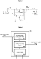
- Fig. 1 shows a schematic diagram of a DC-DC converter connected between the 48 V battery system and the 14 V battery system, wherein unit 1 and unit 2 are two main circuits of the DC-DC converter.
- switch S1 is closed when there is no voltage on capacitor C2
- an arc discharge effect will occur.
- a pre-charging function is generally needed, i.e. capacitor C2 is first pre-charged from 0V to 48 V, then switch S1 is closed to begin transferring power.
- a control circuit is needed to control and/or realize the pre-charging function, and the control circuit needs a differential voltage to operate normally.
- a mechanism capable of providing a differential voltage for normal operation of the control circuit is needed.
- SUNG HOONSUNG "Development of high efficiency bi-directional DC/DC Converter for 48V-12V Dual voltage system in vehicle”,EVS28 INTERNATIONAL ELECTRIC VEHICLE SYMPOSIUM AND EXHIBITION, 3 May 2015 (2015-05-03), pages 1-5, Goyang, Korea
- a system comprising: a control circuit (control circuit, LM5170); a DC-DC converter configured to convert a voltage between a first power supply (14V) and a second power supply (48V), comprising: a first port configured to be connected to the first power supply (14V); a second port configured to be connected to the second power supply (48V); converting means (Unit 1, Unit 2) connected between the first and second ports; a first capacitor (C1) connected between the first port and ground, said ground being configured to be connected to a negative pin of the first power supply (14V) and a negative pin of the second power supply (48V); a second capacitor (C2) connected between the second port and ground; and a security device (Security MOSFET) connected to the control circuit (control circuit, LM5170) and the first port and configured to be connected to the first power supply (14V), wherein the system further comprises: an apparatus (200) connected to the security device (Security MOSFET) and the control circuit (
- the auxiliary power supply generating means comprises a half-wave rectification circuit, and a reference ground of the auxiliary power supply is a positive terminal of the first power supply.
- the half-wave rectification circuit comprises: a floating winding, a first terminal of the floating winding being connected with the first power supply and a second terminal of the floating winding being connected with an anode of a first diode; the first diode, a cathode of the first diode being connected with the voltage supplying means; and a capacitor connected between the first terminal of the floating winding and the cathode of the first diode.
- the auxiliary power supply generating means is a secondary side of a flyback converter, and a primary side of the flyback converter is connected to the first power supply.
- the voltage supplying means comprises: a second diode, an anode of the second diode being connected with a port dedicated to the second power supply, and a cathode of the second diode being connected with the output means; and a third diode, an anode of the third diode being connected with the auxiliary power supply generating means, and a cathode of the third diode being connected with the output means.
- the cathodes of the second diode and the third diode are connected with each other, and a switch is connected between the port dedicated to the second power supply and the second power supply.
- the voltage supplying means outputs the auxiliary power supply through the third diode when the switch is turned off, and outputs the second power supply through the second diode when the switch is turned on.
- the apparatus is configured to supply the differential voltage to a control circuit using the output differential voltage so as to control a DC-DC converter.
- a voltage difference between the power supply output from the voltage supplying means and the first power supply is greater than or equal to 10V.
- a hybrid vehicle comprising the DC-DC converter described above is provided.
- a method for operating a system comprising: supplying a differential voltage by an apparatus (200) which is interconnected with a security device (Security MOSFET) of a DC-DC converter and a control circuit (control circuit, LM5170), comprised by the DC-DC power conversion system, wherein supplying the differential voltage comprises: connecting a first power supply (14V) to an auxiliary power supply generating means (201) and generate (S510) an auxiliary power supply; and receiving the auxiliary power supply (12V/P14V) and a second power supply (48V), and output one of the auxiliary power supply (12V/P14V) and the second power supply (48V) by a voltage supplying means (202); and supplying (S520) by an output means (203) the output from the voltage supplying means (202) and the first power supply (14V) as the differential voltage to the control circuit (control circuit, LM5170) and control the DC-DC converter, in order to ensure a circuit-breaker function (circuit breaker,
- the step of supplying the first power supply and one of the auxiliary power supply and a second power supply externally comprises: supplying the first power supply and the auxiliary power supply externally before the second power supply is turned on; and supplying the first power supply and the second power supply externally after the second power supply is turned on.
- the step of supplying the first power supply and one of the auxiliary power supply and a second power supply externally comprises supplying a differential voltage to a control circuit using the output differential voltage so as to control a DC-DC converter.
- a voltage difference between the first power supply and one of the auxiliary power supply and a second power supply is greater than or equal to 10 V.
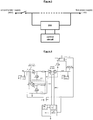
- Fig. 2 shows a schematic block diagram of an apparatus 200 for supplying a differential voltage according to an embodiment of this disclosure.
- the apparatus 200 comprises an auxiliary power supply generating means 201, a voltage supplying means 202 and an output means 203.
- the auxiliary power supply generating means 201 is connected with a first power supply, and configured to generate an auxiliary power supply.
- the voltage supplying means 202 is configured to receive a second power supply and the auxiliary power supply, and output one of the auxiliary power supply and the second power supply.
- the output means 203 is configured to supply the power supply output from the voltage supplying means and the first power supply externally.
- the first power supply is e.g. 14 V
- the second power supply is e.g. 48 V.
- the apparatus 200 can supply a differential voltage, and so another circuit can use this differential voltage to operate normally.
- Fig. 3 shows a schematic diagram of the connections between an apparatus 200 according to an embodiment of this disclosure and a control circuit for controlling and/or realizing a pre-charging function.
- the apparatus 200 is connected between the first power supply (14 V) and the second power supply (48 V), and supplies two voltage outputs to the control circuit.
- the control circuit controls the main circuits in the DC-DC converter, such as unit 1 and unit 2, to be in a step-up mode.
- the two voltages output by the apparatus 200 are a differential voltage, so that the control circuit can operate normally and use the differential voltage to control the DC-DC converter.
- Fig. 4 shows a schematic diagram of a specific circuit of an apparatus for supplying a differential voltage according to an embodiment of this disclosure and a control circuit.
- control circuit is shown as e.g. LM5170 from Texas Instruments, but the control circuit could obviously be specificized as any other suitable circuit.
- control circuit could obviously be specificized as any other suitable circuit.
- Fig. 4 only unit 1 and unit 2 are shown, but those skilled in the art should understand that the number of main circuits in the DC-DC converter is not limited to two, but may be more or less.
- the auxiliary power supply generating means (Auxiliary Power Supply, APS) 201 may comprise a half-wave rectification circuit, and the reference ground of the auxiliary power supply is the positive terminal of the first power supply (14 V).
- the half-wave rectification circuit may comprise a floating winding, a first diode D1 and a capacitor C3.
- a first terminal of the floating winding is connected with the first power supply (14 V), and a second terminal of the floating winding is connected with an anode of the first diode D1.
- a cathode of the first diode D1 is connected with the voltage supplying means 202.
- the capacitor C3 is connected between the first terminal of the floating winding and the cathode of the first diode D1.
- the auxiliary power supply generating means 201 may be a secondary side of a flyback converter, and a primary side of the flyback converter is connected to the first power supply (14 V).
- the auxiliary power supply generating means 201 draws power from the primary side of the flyback converter, in order to provide an auxiliary power supply.
- the primary side of the flyback converter draws power from the first power supply 14 V, in order to supply energy to the auxiliary power supply generating means 201, in order to transfer the auxiliary power supply.
- the voltage supplying means 202 may comprise a second diode D2 and a third diode D3.
- An anode of the second diode D2 is connected with a port dedicated to the second power supply (48 V), and a cathode of the second diode is connected with the output means 203.
- An anode of the third diode D3 is connected with the auxiliary power supply generating means 201, and a cathode of the third diode is connected with the output means 203.
- the cathodes of the second diode D2 and the third diode D3 are connected with each other.
- D2 and D3 are shown as being connected in parallel to a VIN port of LM5170, to supply the auxiliary power supply 12 V/P14 V or the second power supply 48 V to LM5170.
- a switch S1 is connected between the second power supply and the port dedicated to the second power supply (48 V).
- the voltage supplying means 202 outputs the auxiliary power supply 12 V/P14 V through the third diode D3 when the switch S1 is turned off, and outputs the second power supply 48 V through the second diode D2 when the switch S1 is turned on.
- the third diode D3 can prevent a short circuit from occurring between the 48 V port and the 14 V port when the first diode D1 and capacitor C3 have a short circuit
- the second diode D2 can prevent a short circuit from occurring in the 14 V battery system when C2 has a short circuit.
- the output means 203 may simply be specificized as conductive wires connected to D2 and D3 respectively.
- the apparatus 200 may supply the first power supply 14 V and the auxiliary power supply 12 V/P14 V to the control circuit; thus the control circuit can receive a differential voltage having a 12 V voltage difference.
- the apparatus 200 can supply the first power supply 14 V and the second power supply 48 V to the control circuit; thus the control circuit can receive a differential voltage having a 34 V voltage difference.
- the apparatus 200 may be configured to use an output differential voltage to supply a differential voltage to a control circuit such as LM5170, in order to control the DC-DC converter.
- a control circuit such as LM5170
- control circuit LM5170 to ensure a circuit breaker function of a security device, it must receive a differential voltage having a voltage difference greater than 10 V, and the apparatus 200 according to an embodiment of this disclosure can at least supply a differential voltage having a 12 V voltage difference.
- LM5170 can operate normally even when the switch S1 is open.
- control circuit LM5170 may also drive 4 circuits, etc.
- the auxiliary power supply generating means 201 by adjusting the size of components in the apparatus 200, in particular the auxiliary power supply generating means 201, it can be ensured that the voltage difference between the first power supply 14 V and the power supply output by the voltage supplying means 202 is greater than or equal to 10 V.
- the control circuit is connected to a security device of the DC-DC converter.
- the security device comprises two common-source security metal oxide semiconductor field effect transistors (MOSFETs).
- the two security MOSFETs may be N type MOSFETs.
- the pre-charging process of C2 is split into two stages. In the first stage, C1 and C2 are charged from 0V to 14 V; and in the second stage, C2 is further charged to 48 V.
- the two common-source security MOSFETs only act in the first stage; in the second stage, the two common-source security MOSFETs are both turned on, and serve the function of conducting wires.
- a DC-DC converter configured to convert a voltage between a first power supply (e.g. 14 V) and a second power supply (e.g. 48 V) is also provided, comprising a first port, a second port, a first capacitor (C1), a second capacitor (C2) and a security device.
- the first port e.g. a port for the first power supply
- the second port e.g. a port for the second power supply
- the second power supply is configured to be connected to the second power supply (48 V).
- a converting means is connected between the first and second ports.
- the converting means is the main circuits of the DC-DC converter, e.g. unit 1 and unit 2.
- the first capacitor (C1) is connected between the first port and ground, said ground being configured to be connected to a negative pin of the first power supply and a negative pin of the second power supply.
- the second capacitor (C2) is connected between the second port and ground.
- the security device is connected to the first port and configured to be connected to the first power supply, and is connected to the apparatus 200 described above.
- the security device is e.g. two common-source security MOSFETs as shown in Fig. 4 .
- the DC-DC converter is controlled by the differential voltage output by the apparatus 200.
- an embodiment of this disclosure also provides a hybrid vehicle comprising the DC-DC converter described above.
- Fig. 5 shows a schematic flow chart of a method 500 for supplying a differential voltage according to an embodiment of this disclosure.
- an auxiliary power supply is generated with respect to a first power supply as a reference ground.
- the first power supply and one of the auxiliary power supply and a second power supply are supplied externally.
- the step of supplying the first power supply and one of the auxiliary power supply and a second power supply externally comprises: supplying the first power supply and the auxiliary power supply externally before the second power supply is turned on; and supplying the first power supply and the second power supply externally after the second power supply is turned on.
- the step of supplying the first power supply and one of the auxiliary power supply and a second power supply externally comprises supplying a differential voltage to a control circuit using the output differential voltage so as to control a DC-DC converter.
- a voltage difference between the first power supply and one of the auxiliary power supply and a second power supply is greater than or equal to 10 V.
Landscapes
- Engineering & Computer Science (AREA)
- Power Engineering (AREA)
- Transportation (AREA)
- Mechanical Engineering (AREA)
- Life Sciences & Earth Sciences (AREA)
- Sustainable Development (AREA)
- Sustainable Energy (AREA)
- Electric Propulsion And Braking For Vehicles (AREA)
- Dc-Dc Converters (AREA)
Description
- The embodiments of this disclosure relate to an apparatus and a method for supplying a differential voltage, a direct current (DC)-DC converter, and a hybrid vehicle comprising the DC-DC converter.
- In a hybrid vehicle, in order to use high-power loads such as electric compressors, electric heaters, power steering and electric pumps, an additional 48 V battery system level is defined. A DC-DC converter must be arranged between the 48 V battery system and 14 V battery system.
-
Fig. 1 shows a schematic diagram of a DC-DC converter connected between the 48 V battery system and the 14 V battery system, whereinunit 1 andunit 2 are two main circuits of the DC-DC converter. In the circuit connection, if switch S1 is closed when there is no voltage on capacitor C2, an arc discharge effect will occur. To reduce this arc discharge effect as much as possible, a pre-charging function is generally needed, i.e. capacitor C2 is first pre-charged from 0V to 48 V, then switch S1 is closed to begin transferring power. - In general, a control circuit is needed to control and/or realize the pre-charging function, and the control circuit needs a differential voltage to operate normally. Thus, a mechanism capable of providing a differential voltage for normal operation of the control circuit is needed.
- SUNG HOONSUNG: "Development of high efficiency bi-directional DC/DC Converter for 48V-12V Dual voltage system in vehicle",EVS28 INTERNATIONAL ELECTRIC VEHICLE SYMPOSIUM AND EXHIBITION, 3 May 2015 (2015-05-03), pages 1-5, Goyang, Korea
- According to an embodiment of this disclosure, a system comprising: a control circuit (control circuit, LM5170); a DC-DC converter configured to convert a voltage between a first power supply (14V) and a second power supply (48V), comprising: a first port configured to be connected to the first power supply (14V); a second port configured to be connected to the second power supply (48V); converting means (
Unit 1, Unit 2) connected between the first and second ports; a first capacitor (C1) connected between the first port and ground, said ground being configured to be connected to a negative pin of the first power supply (14V) and a negative pin of the second power supply (48V); a second capacitor (C2) connected between the second port and ground; and a security device (Security MOSFET) connected to the control circuit (control circuit, LM5170) and the first port and configured to be connected to the first power supply (14V), wherein the system further comprises: an apparatus (200) connected to the security device (Security MOSFET) and the control circuit (control circuit, LM5170) and configured to supply a differential voltage, said apparatus comprising: an auxiliary power supply generating means (201), which is configured to be connected to the first power supply (14V), and configured to generate an auxiliary power supply (12V/P14V); a voltage supplying means (202) configured to receive the second power supply (48V) and the auxiliary power supply (12V/P14V), and output one of the auxiliary power supply (12V/ P14V) and the second power supply (48V); and an output means (203) configured to supply the output from the voltage supplying means (202) and the first power supply (14V) as the differential voltage to the control circuit (control circuit, LM5170) to control the DC-DC converter, in order to ensure a circuit-breaker function (circuit breaker, BRKS, BRKG) of the security device (Security MOSFET), and to provide for a pre-charge of the first capacitor (C1), and the second capacitor (C2) and to operate the converting means. - In one example, the auxiliary power supply generating means comprises a half-wave rectification circuit, and a reference ground of the auxiliary power supply is a positive terminal of the first power supply.
- In one example, the half-wave rectification circuit comprises: a floating winding, a first terminal of the floating winding being connected with the first power supply and a second terminal of the floating winding being connected with an anode of a first diode; the first diode, a cathode of the first diode being connected with the voltage supplying means; and a capacitor connected between the first terminal of the floating winding and the cathode of the first diode.
- In one example, the auxiliary power supply generating means is a secondary side of a flyback converter, and a primary side of the flyback converter is connected to the first power supply.
- In one example, the voltage supplying means comprises: a second diode, an anode of the second diode being connected with a port dedicated to the second power supply, and a cathode of the second diode being connected with the output means; and a third diode, an anode of the third diode being connected with the auxiliary power supply generating means, and a cathode of the third diode being connected with the output means.
- In one example, the cathodes of the second diode and the third diode are connected with each other, and a switch is connected between the port dedicated to the second power supply and the second power supply.
- In one example, the voltage supplying means outputs the auxiliary power supply through the third diode when the switch is turned off, and outputs the second power supply through the second diode when the switch is turned on.
- In one example, the apparatus is configured to supply the differential voltage to a control circuit using the output differential voltage so as to control a DC-DC converter.
- In one example, a voltage difference between the power supply output from the voltage supplying means and the first power supply is greater than or equal to 10V.
- According to another embodiment of this disclosure, a hybrid vehicle comprising the DC-DC converter described above is provided.
- According to another embodiment of this disclosure, a method for operating a system comprising: supplying a differential voltage by an apparatus (200) which is interconnected with a security device (Security MOSFET) of a DC-DC converter and a control circuit (control circuit, LM5170), comprised by the DC-DC power conversion system, wherein supplying the differential voltage comprises: connecting a first power supply (14V) to an auxiliary power supply generating means (201) and generate (S510) an auxiliary power supply; and receiving the auxiliary power supply (12V/P14V) and a second power supply (48V), and output one of the auxiliary power supply (12V/P14V) and the second power supply (48V) by a voltage supplying means (202); and supplying (S520) by an output means (203) the output from the voltage supplying means (202) and the first power supply (14V) as the differential voltage to the control circuit (control circuit, LM5170) and control the DC-DC converter, in order to ensure a circuit-breaker function (circuit breaker, BRKS, BRKG) of the security device (Security MOSFET), and to provide for a precharge of a first capacitor (C1), when connected to the first power supply (14V), and a second capacitor (C2), when connected to the second power supply (48V), comprised by the DC-DC converter, and to operate the converting means.
- In one example, the step of supplying the first power supply and one of the auxiliary power supply and a second power supply externally comprises: supplying the first power supply and the auxiliary power supply externally before the second power supply is turned on; and supplying the first power supply and the second power supply externally after the second power supply is turned on.
- In one example, the step of supplying the first power supply and one of the auxiliary power supply and a second power supply externally comprises supplying a differential voltage to a control circuit using the output differential voltage so as to control a DC-DC converter.
- In one example, a voltage difference between the first power supply and one of the auxiliary power supply and a second power supply is greater than or equal to 10 V.
- Thus, according to an embodiment of this disclosure, there is a voltage difference between the first power supply and the power supply supplied by the output means, so a differential voltage can be supplied, and so another circuit can use this differential voltage to operate normally.
- The following detailed description, which is aided by the accompanying drawings, will enable this disclosure to be understood more easily, wherein identical labels designate units with the same structure, and wherein:
-
Fig. 1 shows a schematic diagram of a DC-DC converter connected between the 48 V battery system and the 14 V battery system; -
Fig. 2 shows a schematic block diagram of an apparatus for supplying a differential voltage according to an embodiment of this disclosure; -
Fig. 3 shows a schematic diagram of the connections between an apparatus according to an embodiment of this disclosure and a control circuit for controlling and/or realizing a pre-charging function; -
Fig. 4 shows a schematic diagram of a specific circuit of an apparatus for supplying a differential voltage according to an embodiment of this disclosure and a control circuit; and -
Fig. 5 shows a schematic flow chart of a method for supplying a differential voltage according to an embodiment of this disclosure. - The technical solutions in embodiments of the present invention are described clearly and fully below in conjunction with the accompanying drawings in embodiments of the present invention. Clearly, the embodiments described are some, not all, of the embodiments of the present invention. The scope of protection of this invention is only limited by the appended claims.
-
Fig. 2 shows a schematic block diagram of anapparatus 200 for supplying a differential voltage according to an embodiment of this disclosure. - As shown in
Fig. 2 , theapparatus 200 comprises an auxiliary power supply generating means 201, a voltage supplying means 202 and an output means 203. - The auxiliary power supply generating means 201 is connected with a first power supply, and configured to generate an auxiliary power supply. The voltage supplying means 202 is configured to receive a second power supply and the auxiliary power supply, and output one of the auxiliary power supply and the second power supply. The output means 203 is configured to supply the power supply output from the voltage supplying means and the first power supply externally.
- In one example, the first power supply is e.g. 14 V, and the second power supply is e.g. 48 V.
- Thus, according to an embodiment of this disclosure, there is a voltage difference between the first power supply and the power supply supplied by the output means 203, so the
apparatus 200 can supply a differential voltage, and so another circuit can use this differential voltage to operate normally. -
Fig. 3 shows a schematic diagram of the connections between anapparatus 200 according to an embodiment of this disclosure and a control circuit for controlling and/or realizing a pre-charging function. - As shown in
Fig. 3 , theapparatus 200 is connected between the first power supply (14 V) and the second power supply (48 V), and supplies two voltage outputs to the control circuit. The control circuit controls the main circuits in the DC-DC converter, such asunit 1 andunit 2, to be in a step-up mode. The two voltages output by theapparatus 200 are a differential voltage, so that the control circuit can operate normally and use the differential voltage to control the DC-DC converter. -
Fig. 4 shows a schematic diagram of a specific circuit of an apparatus for supplying a differential voltage according to an embodiment of this disclosure and a control circuit. - In
Fig. 4 , the control circuit is shown as e.g. LM5170 from Texas Instruments, but the control circuit could obviously be specificized as any other suitable circuit. InFig. 4 , onlyunit 1 andunit 2 are shown, but those skilled in the art should understand that the number of main circuits in the DC-DC converter is not limited to two, but may be more or less. - As shown in
Fig. 4 , the auxiliary power supply generating means (Auxiliary Power Supply, APS) 201 may comprise a half-wave rectification circuit, and the reference ground of the auxiliary power supply is the positive terminal of the first power supply (14 V). - According to an embodiment of this disclosure, the half-wave rectification circuit may comprise a floating winding, a first diode D1 and a capacitor C3.
- A first terminal of the floating winding is connected with the first power supply (14 V), and a second terminal of the floating winding is connected with an anode of the first diode D1. A cathode of the first diode D1 is connected with the voltage supplying means 202. The capacitor C3 is connected between the first terminal of the floating winding and the cathode of the first diode D1.
- The auxiliary power supply generating means 201 can generate a false voltage signal of 12 V/P14 V based on the first power supply (14 V); the voltage of the false voltage signal relative to ground may be 12 V + 14 V = 26 V.
- The auxiliary power supply generating means 201 may be a secondary side of a flyback converter, and a primary side of the flyback converter is connected to the first power supply (14 V). The auxiliary power supply generating means 201 draws power from the primary side of the flyback converter, in order to provide an auxiliary power supply. In other words, the primary side of the flyback converter draws power from the
first power supply 14 V, in order to supply energy to the auxiliary power supply generating means 201, in order to transfer the auxiliary power supply. - As shown in
Fig. 4 , the voltage supplying means 202 may comprise a second diode D2 and a third diode D3. - An anode of the second diode D2 is connected with a port dedicated to the second power supply (48 V), and a cathode of the second diode is connected with the output means 203. An anode of the third diode D3 is connected with the auxiliary power supply generating means 201, and a cathode of the third diode is connected with the output means 203.
- In one example, the cathodes of the second diode D2 and the third diode D3 are connected with each other. Thus, in
Fig. 4 , D2 and D3 are shown as being connected in parallel to a VIN port of LM5170, to supply theauxiliary power supply 12 V/P14 V or thesecond power supply 48 V to LM5170. - In one example, a switch S1 is connected between the second power supply and the port dedicated to the second power supply (48 V). The voltage supplying means 202 outputs the
auxiliary power supply 12 V/P14 V through the third diode D3 when the switch S1 is turned off, and outputs thesecond power supply 48 V through the second diode D2 when the switch S1 is turned on. - In addition, the third diode D3 can prevent a short circuit from occurring between the 48 V port and the 14 V port when the first diode D1 and capacitor C3 have a short circuit, and the second diode D2 can prevent a short circuit from occurring in the 14 V battery system when C2 has a short circuit.
- The output means 203 may simply be specificized as conductive wires connected to D2 and D3 respectively.
- In this way, before the switch S1 has been turned on, the
apparatus 200 may supply thefirst power supply 14 V and theauxiliary power supply 12 V/P14 V to the control circuit; thus the control circuit can receive a differential voltage having a 12 V voltage difference. After the switch S1 has been turned on, theapparatus 200 can supply thefirst power supply 14 V and thesecond power supply 48 V to the control circuit; thus the control circuit can receive a differential voltage having a 34 V voltage difference. - Thus, the
apparatus 200 may be configured to use an output differential voltage to supply a differential voltage to a control circuit such as LM5170, in order to control the DC-DC converter. - Specifically, with regard to control circuit LM5170, to ensure a circuit breaker function of a security device, it must receive a differential voltage having a voltage difference greater than 10 V, and the
apparatus 200 according to an embodiment of this disclosure can at least supply a differential voltage having a 12 V voltage difference. - Thus, when the
apparatus 200 according to an embodiment of this disclosure is used, LM5170 can operate normally even when the switch S1 is open. - Although the main circuits of the DC-DC converter shown in
Fig. 4 only comprise the twomain circuits unit 1 andunit 2, it can be understood that control circuit LM5170 may also drive 4 circuits, etc. - In addition, by adjusting the size of components in the
apparatus 200, in particular the auxiliary power supply generating means 201, it can be ensured that the voltage difference between thefirst power supply 14 V and the power supply output by the voltage supplying means 202 is greater than or equal to 10 V. - In addition, since discrete analogue devices are used to realize the
apparatus 200, the structure is simple and the cost is low. - The control circuit is connected to a security device of the DC-DC converter. As shown in
Fig. 4 , the security device comprises two common-source security metal oxide semiconductor field effect transistors (MOSFETs). The two security MOSFETs may be N type MOSFETs. - The pre-charging process of C2 is split into two stages. In the first stage, C1 and C2 are charged from 0V to 14 V; and in the second stage, C2 is further charged to 48 V. The two common-source security MOSFETs only act in the first stage; in the second stage, the two common-source security MOSFETs are both turned on, and serve the function of conducting wires.
- According to an embodiment of this disclosure, referring to
Fig. 4 , a DC-DC converter configured to convert a voltage between a first power supply (e.g. 14 V) and a second power supply (e.g. 48 V) is also provided, comprising a first port, a second port, a first capacitor (C1), a second capacitor (C2) and a security device. - The first port, e.g. a port for the first power supply, is configured to be connected to the first power supply (14 V). The second port, e.g. a port for the second power supply, is configured to be connected to the second power supply (48 V). A converting means is connected between the first and second ports. Here, the converting means is the main circuits of the DC-DC converter,
e.g. unit 1 andunit 2. The first capacitor (C1) is connected between the first port and ground, said ground being configured to be connected to a negative pin of the first power supply and a negative pin of the second power supply. The second capacitor (C2) is connected between the second port and ground. The security device is connected to the first port and configured to be connected to the first power supply, and is connected to theapparatus 200 described above. The security device is e.g. two common-source security MOSFETs as shown inFig. 4 . - The DC-DC converter is controlled by the differential voltage output by the
apparatus 200. - In addition, an embodiment of this disclosure also provides a hybrid vehicle comprising the DC-DC converter described above.
-
Fig. 5 shows a schematic flow chart of amethod 500 for supplying a differential voltage according to an embodiment of this disclosure. - As shown in
Fig. 5 , in S510 of themethod 500, an auxiliary power supply is generated with respect to a first power supply as a reference ground. In S520, the first power supply and one of the auxiliary power supply and a second power supply are supplied externally. - Thus, according to an embodiment of this disclosure, there is a voltage difference between the first power supply and the power supply supplied, so a differential voltage can be supplied, and so another circuit can use this differential voltage to operate normally.
- In one example, the step of supplying the first power supply and one of the auxiliary power supply and a second power supply externally comprises: supplying the first power supply and the auxiliary power supply externally before the second power supply is turned on; and supplying the first power supply and the second power supply externally after the second power supply is turned on.
- In one example, the step of supplying the first power supply and one of the auxiliary power supply and a second power supply externally comprises supplying a differential voltage to a control circuit using the output differential voltage so as to control a DC-DC converter.
- In one example, a voltage difference between the first power supply and one of the auxiliary power supply and a second power supply is greater than or equal to 10 V.
- It should be noted that for clarity and simplicity, only parts relevant to embodiments of the present invention are shown in
Figs. 2 to 4 . However, those skilled in the art should understand that the apparatuses or devices shown inFigs. 2 to 4 may comprise other necessary units. - The embodiments above are merely particular embodiments of the present invention, but the scope of protection of the present invention is only limited by the appended claims.
Claims (12)
- A system comprising: a control circuit (control circuit, LM5170); a DC-DC converter configured to convert a voltage between a first power supply (14V) and a second power supply (48V), comprising: a first port configured to be connected to the first power supply (14V); a second port configured to be connected to the second power supply (48V); converting means (Unit 1, Unit 2) connected between the first and second ports; a first capacitor (C1) connected between the first port and ground, said ground being configured to be connected to a negative pin of the first power supply (14V) and a negative pin of the second power supply (48V); a second capacitor (C2) connected between the second port and ground; and a security device (Security MOSFET) connected to the control circuit (control circuit, LM5170) and the first port and configured to be connected to the first power supply (14V);
characterized in that the system further comprises: an apparatus (200) connected to the security device (Security MOSFET) and the control circuit (control circuit, LM5170) and configured to supply a differential voltage, said apparatus comprising: an auxiliary power supply generating means (201), which is configured to be connected to the first power supply (14V), and configured to generate an auxiliary power supply (12V/P14V); a voltage supplying means (202) configured to receive the second power supply (48V) and the auxiliary power supply (12V/P14V), and output one of the auxiliary power supply (12V/P14V) and the second power supply (48V); and an output means (203) configured to supply the output from the voltage supplying means (202) and the first power supply (14V) as the differential voltage to the control circuit (control circuit, LM5170) to control the DC-DC converter, in order
to ensure a circuit-breaker function (circuit breaker, BRKS, BRKG) of the security device (Security MOSFET), and to provide for a pre-charge of the first capacitor (C1), and the second capacitor (C2). - The system of claim 1, wherein the auxiliary power supply generating means comprises a half-wave rectification circuit, and a reference ground of the auxiliary power supply is a positive terminal of the first power supply.
- The system of claim 2, wherein the half-wave rectification circuit comprises:a floating winding, a first terminal of the floating winding is connected with the first power supply and a second terminal thereof is connected with an anode of a first diode;the first diode, a cathode of the first diode is connected with the voltage supplying means; anda capacitor connected between the first terminal of the floating winding and the cathode of the first diode.
- The system of claim 2 or 3, wherein the auxiliary power supply generating means is a secondary side of a flyback converter, and a primary side of the flyback converter is connected to the first power supply.
- The system of any one of claims 1-4, wherein the voltage supplying means comprises:a second diode, an anode of the second diode is connected with a port dedicated to the second power supply, and a cathode thereof is connected with the output means; anda third diode, an anode of the third diode is connected with the auxiliary power supply generating means, and a cathode thereof is connected with the output means.
- The system of claim 5, wherein the cathodes of the second diode and the third diode are connected with each other, and a switch is connected between the port dedicated to the second power supply and the second power supply.
- The system of claim 6, wherein the voltage supplying means outputs the auxiliary power supply through the third diode when the switch is turned off, and outputs the second power supply through the second diode when the switch is turned on.
- The system of any one of claims 1-7, wherein a voltage difference between the power supply output from the voltage supplying means and the first power supply is greater than or equal to 10V.
- A hybrid vehicle comprising the system of any one of claims 1-8.
- A method for operating the system of claim 1, comprising: supplying the differential voltage by the apparatus (200), wherein supplying the differential voltage comprises: connecting the first power supply (14V) to the auxiliary power supply generating means (201) and generate (S510) an auxiliary power supply; and receiving the auxiliary power supply (12V/P14V) and the second power supply (48V), and output one of the auxiliary power supply (12V/P14V) and the second power supply (48V) by the voltage supplying means (202); and supplying (S520) by the output means (203) the output from the voltage supplying means (202) and the first power supply (14V) as the differential voltage to the control circuit (control circuit, LM5170) and control the DC-DC converter, in order to ensure a circuit-breaker function (circuit breaker, BRKS, BRKG) of the security device (Security MOSFET), and to provide for a pre-charge of the first capacitor (C1) and the second capacitor (C2).
- The method for operating the system of claim 10, wherein the supplying the first power supply and one of the auxiliary power supply and a second power supply externally comprises:supplying the first power supply and the auxiliary power supply externally before the second power supply is turned on; andsupplying the first power supply and the second power supply externally after the second power supply is turned on.
- The method for operating the system of claim 10 or 11, wherein a voltage difference between the first power supply and one of the auxiliary power supply and a second power supply is greater than or equal to 10V.
Applications Claiming Priority (1)
| Application Number | Priority Date | Filing Date | Title |
|---|---|---|---|
| CN201610194621.7A CN107294381B (en) | 2016-03-31 | 2016-03-31 | Apparatus and method for providing differential voltage and DC-DC converter |
Publications (2)
| Publication Number | Publication Date |
|---|---|
| EP3226378A1 EP3226378A1 (en) | 2017-10-04 |
| EP3226378B1 true EP3226378B1 (en) | 2021-05-19 |
Family
ID=58464436
Family Applications (1)
| Application Number | Title | Priority Date | Filing Date |
|---|---|---|---|
| EP17164330.7A Active EP3226378B1 (en) | 2016-03-31 | 2017-03-31 | Apparatus and method for supplying differential voltage, and dc-dc converter |
Country Status (2)
| Country | Link |
|---|---|
| EP (1) | EP3226378B1 (en) |
| CN (1) | CN107294381B (en) |
Citations (2)
| Publication number | Priority date | Publication date | Assignee | Title |
|---|---|---|---|---|
| US6208117B1 (en) * | 1999-07-30 | 2001-03-27 | Fujitsu Limited | Battery pack and electronic apparatus using the same |
| JP2005135672A (en) * | 2003-10-29 | 2005-05-26 | Sony Corp | Battery pack |
Family Cites Families (9)
| Publication number | Priority date | Publication date | Assignee | Title |
|---|---|---|---|---|
| US6700808B2 (en) * | 2002-02-08 | 2004-03-02 | Mobility Electronics, Inc. | Dual input AC and DC power supply having a programmable DC output utilizing a secondary buck converter |
| JP3826929B2 (en) * | 2003-10-27 | 2006-09-27 | ソニー株式会社 | Battery pack |
| CN1329221C (en) * | 2004-01-29 | 2007-08-01 | 三菱电机株式会社 | Auxiliary power supply for vehicle |
| TWI270998B (en) * | 2005-09-27 | 2007-01-11 | Liou Ching Shiung | A voltage supplying apparatus using a fuel cell |
| GB2476508B (en) * | 2009-12-23 | 2013-08-21 | Control Tech Ltd | Voltage compensation for photovoltaic generator systems |
| DE102012200804A1 (en) * | 2012-01-20 | 2013-07-25 | Continental Automotive Gmbh | On-board network and method for operating a vehicle electrical system |
| CN103501115A (en) * | 2013-10-15 | 2014-01-08 | 扬州瑞控汽车电子有限公司 | Interleaved and parallel working direct-current (DC) step-down circuit |
| CN204055403U (en) * | 2014-09-02 | 2014-12-31 | 中国东方电气集团有限公司 | A kind of redundant circuit structure of accessory feed of electric-vehicle-mounted DC/DC device |
| CN104901378A (en) * | 2015-04-17 | 2015-09-09 | 丁振荣 | Mobile power supply |
-
2016
- 2016-03-31 CN CN201610194621.7A patent/CN107294381B/en active Active
-
2017
- 2017-03-31 EP EP17164330.7A patent/EP3226378B1/en active Active
Patent Citations (2)
| Publication number | Priority date | Publication date | Assignee | Title |
|---|---|---|---|---|
| US6208117B1 (en) * | 1999-07-30 | 2001-03-27 | Fujitsu Limited | Battery pack and electronic apparatus using the same |
| JP2005135672A (en) * | 2003-10-29 | 2005-05-26 | Sony Corp | Battery pack |
Non-Patent Citations (2)
| Title |
|---|
| O. GARCIA ET AL: "Automotive DC-DC bidirectional converter made with many interleaved buck stages", IEEE TRANSACTIONS ON POWER ELECTRONICS, vol. 21, no. 3, 1 May 2006 (2006-05-01), pages 578 - 586, XP055071613, ISSN: 0885-8993, DOI: 10.1109/TPEL.2006.872379 * |
| SUNG HOONSUNG: "Development of high efficiency bi-directional DC/DC Converter for 48V-12V Dual voltage system in vehicle", EVS28 INTERNATIONAL ELECTRIC VEHICLE SYMPOSIUM AND EXHIBITION, 3 May 2015 (2015-05-03), Goyang, Korea, pages 1 - 5, XP055535657 * |
Also Published As
| Publication number | Publication date |
|---|---|
| CN107294381A (en) | 2017-10-24 |
| CN107294381B (en) | 2021-05-04 |
| EP3226378A1 (en) | 2017-10-04 |
Similar Documents
| Publication | Publication Date | Title |
|---|---|---|
| US20210126541A1 (en) | Power conversion system | |
| US9806618B2 (en) | Power converting device and power conditioner using the same | |
| JP6296608B2 (en) | Uninterruptible power system | |
| US20180138730A1 (en) | Universal current charger | |
| CN105391281A (en) | System and method for a switch having a normally-on transistor and a normally-off transistor | |
| US10940813B2 (en) | Universal platform architecture for hybrid more electric aircraft | |
| EP3226395B1 (en) | Pre-charging circuit, dc-dc converter and hybrid vehicle | |
| JP6362283B2 (en) | Electric vehicle charging equipment and charging method | |
| US20200052601A1 (en) | Power conversion system | |
| US11973426B2 (en) | Universal buck converter | |
| US9716445B2 (en) | Inverter grid-connected system and method for implementing three-phase alternating current grid-connected transition | |
| CN103944420B (en) | Power supply system and control method thereof | |
| US12500424B2 (en) | Power supply system and solar photovoltaic inverter | |
| US9257892B2 (en) | Method and device for current driven electric energy conversion | |
| EP3206291B1 (en) | Apparatus and method for low frequency power inverter | |
| US9998019B2 (en) | DC-DC converter, and solar power controller and mobile body using same | |
| US20140001862A1 (en) | Uninterruptible power supply | |
| CN107294381B (en) | Apparatus and method for providing differential voltage and DC-DC converter | |
| CN115483675B (en) | Power supply switching device and multi-input power supply | |
| CN111106667A (en) | Power supply device and power supply system | |
| WO2016159517A1 (en) | H-bridge multilevel inverter | |
| CN213990500U (en) | Auxiliary power supply circuit and power supply system | |
| US10038224B2 (en) | Power supply device | |
| CN111327194B (en) | Power converter and power supply device sharing direct-current power supply | |
| JP6817579B2 (en) | Power conversion circuit and power transmission system |
Legal Events
| Date | Code | Title | Description |
|---|---|---|---|
| PUAI | Public reference made under article 153(3) epc to a published international application that has entered the european phase |
Free format text: ORIGINAL CODE: 0009012 |
|
| STAA | Information on the status of an ep patent application or granted ep patent |
Free format text: STATUS: EXAMINATION IS IN PROGRESS |
|
| 17P | Request for examination filed |
Effective date: 20170331 |
|
| AK | Designated contracting states |
Kind code of ref document: A1 Designated state(s): AL AT BE BG CH CY CZ DE DK EE ES FI FR GB GR HR HU IE IS IT LI LT LU LV MC MK MT NL NO PL PT RO RS SE SI SK SM TR |
|
| AX | Request for extension of the european patent |
Extension state: BA ME |
|
| GRAP | Despatch of communication of intention to grant a patent |
Free format text: ORIGINAL CODE: EPIDOSNIGR1 |
|
| STAA | Information on the status of an ep patent application or granted ep patent |
Free format text: STATUS: GRANT OF PATENT IS INTENDED |
|
| RIC1 | Information provided on ipc code assigned before grant |
Ipc: H02M 1/00 20060101ALN20200409BHEP Ipc: B60L 58/20 20190101ALI20200409BHEP Ipc: H02J 7/00 20060101ALI20200409BHEP Ipc: H02J 1/10 20060101ALI20200409BHEP Ipc: B60L 1/00 20060101ALI20200409BHEP Ipc: H02M 3/335 20060101AFI20200409BHEP Ipc: B60L 1/02 20060101ALI20200409BHEP |
|
| INTG | Intention to grant announced |
Effective date: 20200424 |
|
| GRAJ | Information related to disapproval of communication of intention to grant by the applicant or resumption of examination proceedings by the epo deleted |
Free format text: ORIGINAL CODE: EPIDOSDIGR1 |
|
| STAA | Information on the status of an ep patent application or granted ep patent |
Free format text: STATUS: EXAMINATION IS IN PROGRESS |
|
| INTC | Intention to grant announced (deleted) | ||
| REG | Reference to a national code |
Ref country code: DE Ref legal event code: R079 Ref document number: 602017038714 Country of ref document: DE Free format text: PREVIOUS MAIN CLASS: H02J0007000000 Ipc: H02M0003335000 |
|
| RIC1 | Information provided on ipc code assigned before grant |
Ipc: H02J 1/10 20060101ALI20201002BHEP Ipc: B60L 1/00 20060101ALI20201002BHEP Ipc: H02J 7/00 20060101ALI20201002BHEP Ipc: B60L 1/02 20060101ALI20201002BHEP Ipc: B60L 58/20 20190101ALI20201002BHEP Ipc: H02M 1/00 20060101ALN20201002BHEP Ipc: H02M 3/335 20060101AFI20201002BHEP |
|
| RIC1 | Information provided on ipc code assigned before grant |
Ipc: H02J 7/00 20060101ALI20201009BHEP Ipc: H02M 1/00 20060101ALN20201009BHEP Ipc: H02M 3/335 20060101AFI20201009BHEP Ipc: B60L 1/00 20060101ALI20201009BHEP Ipc: B60L 58/20 20190101ALI20201009BHEP Ipc: H02J 1/10 20060101ALI20201009BHEP Ipc: B60L 1/02 20060101ALI20201009BHEP |
|
| RIC1 | Information provided on ipc code assigned before grant |
Ipc: H02J 7/00 20060101ALI20201022BHEP Ipc: H02M 3/335 20060101AFI20201022BHEP Ipc: B60L 58/20 20190101ALI20201022BHEP Ipc: B60L 1/00 20060101ALI20201022BHEP Ipc: H02M 1/00 20060101ALN20201022BHEP Ipc: H02J 1/10 20060101ALI20201022BHEP Ipc: B60L 1/02 20060101ALI20201022BHEP |
|
| GRAP | Despatch of communication of intention to grant a patent |
Free format text: ORIGINAL CODE: EPIDOSNIGR1 |
|
| STAA | Information on the status of an ep patent application or granted ep patent |
Free format text: STATUS: GRANT OF PATENT IS INTENDED |
|
| RIC1 | Information provided on ipc code assigned before grant |
Ipc: H02M 3/335 20060101AFI20201030BHEP Ipc: H02J 1/10 20060101ALI20201030BHEP Ipc: B60L 1/02 20060101ALI20201030BHEP Ipc: B60L 58/20 20190101ALI20201030BHEP Ipc: H02J 7/00 20060101ALI20201030BHEP Ipc: B60L 1/00 20060101ALI20201030BHEP Ipc: H02M 1/00 20060101ALN20201030BHEP |
|
| INTG | Intention to grant announced |
Effective date: 20201130 |
|
| GRAS | Grant fee paid |
Free format text: ORIGINAL CODE: EPIDOSNIGR3 |
|
| GRAA | (expected) grant |
Free format text: ORIGINAL CODE: 0009210 |
|
| STAA | Information on the status of an ep patent application or granted ep patent |
Free format text: STATUS: THE PATENT HAS BEEN GRANTED |
|
| AK | Designated contracting states |
Kind code of ref document: B1 Designated state(s): AL AT BE BG CH CY CZ DE DK EE ES FI FR GB GR HR HU IE IS IT LI LT LU LV MC MK MT NL NO PL PT RO RS SE SI SK SM TR |
|
| REG | Reference to a national code |
Ref country code: GB Ref legal event code: FG4D |
|
| REG | Reference to a national code |
Ref country code: CH Ref legal event code: EP |
|
| REG | Reference to a national code |
Ref country code: DE Ref legal event code: R096 Ref document number: 602017038714 Country of ref document: DE |
|
| REG | Reference to a national code |
Ref country code: AT Ref legal event code: REF Ref document number: 1394961 Country of ref document: AT Kind code of ref document: T Effective date: 20210615 |
|
| REG | Reference to a national code |
Ref country code: IE Ref legal event code: FG4D |
|
| REG | Reference to a national code |
Ref country code: LT Ref legal event code: MG9D |
|
| REG | Reference to a national code |
Ref country code: AT Ref legal event code: MK05 Ref document number: 1394961 Country of ref document: AT Kind code of ref document: T Effective date: 20210519 |
|
| REG | Reference to a national code |
Ref country code: NL Ref legal event code: MP Effective date: 20210519 |
|
| PG25 | Lapsed in a contracting state [announced via postgrant information from national office to epo] |
Ref country code: HR Free format text: LAPSE BECAUSE OF FAILURE TO SUBMIT A TRANSLATION OF THE DESCRIPTION OR TO PAY THE FEE WITHIN THE PRESCRIBED TIME-LIMIT Effective date: 20210519 Ref country code: AT Free format text: LAPSE BECAUSE OF FAILURE TO SUBMIT A TRANSLATION OF THE DESCRIPTION OR TO PAY THE FEE WITHIN THE PRESCRIBED TIME-LIMIT Effective date: 20210519 Ref country code: BG Free format text: LAPSE BECAUSE OF FAILURE TO SUBMIT A TRANSLATION OF THE DESCRIPTION OR TO PAY THE FEE WITHIN THE PRESCRIBED TIME-LIMIT Effective date: 20210819 Ref country code: FI Free format text: LAPSE BECAUSE OF FAILURE TO SUBMIT A TRANSLATION OF THE DESCRIPTION OR TO PAY THE FEE WITHIN THE PRESCRIBED TIME-LIMIT Effective date: 20210519 Ref country code: LT Free format text: LAPSE BECAUSE OF FAILURE TO SUBMIT A TRANSLATION OF THE DESCRIPTION OR TO PAY THE FEE WITHIN THE PRESCRIBED TIME-LIMIT Effective date: 20210519 |
|
| PG25 | Lapsed in a contracting state [announced via postgrant information from national office to epo] |
Ref country code: GR Free format text: LAPSE BECAUSE OF FAILURE TO SUBMIT A TRANSLATION OF THE DESCRIPTION OR TO PAY THE FEE WITHIN THE PRESCRIBED TIME-LIMIT Effective date: 20210820 Ref country code: IS Free format text: LAPSE BECAUSE OF FAILURE TO SUBMIT A TRANSLATION OF THE DESCRIPTION OR TO PAY THE FEE WITHIN THE PRESCRIBED TIME-LIMIT Effective date: 20210919 Ref country code: LV Free format text: LAPSE BECAUSE OF FAILURE TO SUBMIT A TRANSLATION OF THE DESCRIPTION OR TO PAY THE FEE WITHIN THE PRESCRIBED TIME-LIMIT Effective date: 20210519 Ref country code: PT Free format text: LAPSE BECAUSE OF FAILURE TO SUBMIT A TRANSLATION OF THE DESCRIPTION OR TO PAY THE FEE WITHIN THE PRESCRIBED TIME-LIMIT Effective date: 20210920 Ref country code: NO Free format text: LAPSE BECAUSE OF FAILURE TO SUBMIT A TRANSLATION OF THE DESCRIPTION OR TO PAY THE FEE WITHIN THE PRESCRIBED TIME-LIMIT Effective date: 20210819 Ref country code: PL Free format text: LAPSE BECAUSE OF FAILURE TO SUBMIT A TRANSLATION OF THE DESCRIPTION OR TO PAY THE FEE WITHIN THE PRESCRIBED TIME-LIMIT Effective date: 20210519 Ref country code: RS Free format text: LAPSE BECAUSE OF FAILURE TO SUBMIT A TRANSLATION OF THE DESCRIPTION OR TO PAY THE FEE WITHIN THE PRESCRIBED TIME-LIMIT Effective date: 20210519 Ref country code: SE Free format text: LAPSE BECAUSE OF FAILURE TO SUBMIT A TRANSLATION OF THE DESCRIPTION OR TO PAY THE FEE WITHIN THE PRESCRIBED TIME-LIMIT Effective date: 20210519 |
|
| PG25 | Lapsed in a contracting state [announced via postgrant information from national office to epo] |
Ref country code: NL Free format text: LAPSE BECAUSE OF FAILURE TO SUBMIT A TRANSLATION OF THE DESCRIPTION OR TO PAY THE FEE WITHIN THE PRESCRIBED TIME-LIMIT Effective date: 20210519 |
|
| PG25 | Lapsed in a contracting state [announced via postgrant information from national office to epo] |
Ref country code: SM Free format text: LAPSE BECAUSE OF FAILURE TO SUBMIT A TRANSLATION OF THE DESCRIPTION OR TO PAY THE FEE WITHIN THE PRESCRIBED TIME-LIMIT Effective date: 20210519 Ref country code: SK Free format text: LAPSE BECAUSE OF FAILURE TO SUBMIT A TRANSLATION OF THE DESCRIPTION OR TO PAY THE FEE WITHIN THE PRESCRIBED TIME-LIMIT Effective date: 20210519 Ref country code: EE Free format text: LAPSE BECAUSE OF FAILURE TO SUBMIT A TRANSLATION OF THE DESCRIPTION OR TO PAY THE FEE WITHIN THE PRESCRIBED TIME-LIMIT Effective date: 20210519 Ref country code: CZ Free format text: LAPSE BECAUSE OF FAILURE TO SUBMIT A TRANSLATION OF THE DESCRIPTION OR TO PAY THE FEE WITHIN THE PRESCRIBED TIME-LIMIT Effective date: 20210519 Ref country code: DK Free format text: LAPSE BECAUSE OF FAILURE TO SUBMIT A TRANSLATION OF THE DESCRIPTION OR TO PAY THE FEE WITHIN THE PRESCRIBED TIME-LIMIT Effective date: 20210519 Ref country code: RO Free format text: LAPSE BECAUSE OF FAILURE TO SUBMIT A TRANSLATION OF THE DESCRIPTION OR TO PAY THE FEE WITHIN THE PRESCRIBED TIME-LIMIT Effective date: 20210519 Ref country code: ES Free format text: LAPSE BECAUSE OF FAILURE TO SUBMIT A TRANSLATION OF THE DESCRIPTION OR TO PAY THE FEE WITHIN THE PRESCRIBED TIME-LIMIT Effective date: 20210519 |
|
| REG | Reference to a national code |
Ref country code: DE Ref legal event code: R097 Ref document number: 602017038714 Country of ref document: DE |
|
| PLBE | No opposition filed within time limit |
Free format text: ORIGINAL CODE: 0009261 |
|
| STAA | Information on the status of an ep patent application or granted ep patent |
Free format text: STATUS: NO OPPOSITION FILED WITHIN TIME LIMIT |
|
| 26N | No opposition filed |
Effective date: 20220222 |
|
| PG25 | Lapsed in a contracting state [announced via postgrant information from national office to epo] |
Ref country code: IS Free format text: LAPSE BECAUSE OF FAILURE TO SUBMIT A TRANSLATION OF THE DESCRIPTION OR TO PAY THE FEE WITHIN THE PRESCRIBED TIME-LIMIT Effective date: 20210919 Ref country code: AL Free format text: LAPSE BECAUSE OF FAILURE TO SUBMIT A TRANSLATION OF THE DESCRIPTION OR TO PAY THE FEE WITHIN THE PRESCRIBED TIME-LIMIT Effective date: 20210519 |
|
| PG25 | Lapsed in a contracting state [announced via postgrant information from national office to epo] |
Ref country code: IT Free format text: LAPSE BECAUSE OF FAILURE TO SUBMIT A TRANSLATION OF THE DESCRIPTION OR TO PAY THE FEE WITHIN THE PRESCRIBED TIME-LIMIT Effective date: 20210519 |
|
| PG25 | Lapsed in a contracting state [announced via postgrant information from national office to epo] |
Ref country code: MC Free format text: LAPSE BECAUSE OF FAILURE TO SUBMIT A TRANSLATION OF THE DESCRIPTION OR TO PAY THE FEE WITHIN THE PRESCRIBED TIME-LIMIT Effective date: 20210519 |
|
| REG | Reference to a national code |
Ref country code: CH Ref legal event code: PL |
|
| GBPC | Gb: european patent ceased through non-payment of renewal fee |
Effective date: 20220331 |
|
| REG | Reference to a national code |
Ref country code: BE Ref legal event code: MM Effective date: 20220331 |
|
| PG25 | Lapsed in a contracting state [announced via postgrant information from national office to epo] |
Ref country code: LU Free format text: LAPSE BECAUSE OF NON-PAYMENT OF DUE FEES Effective date: 20220331 Ref country code: LI Free format text: LAPSE BECAUSE OF NON-PAYMENT OF DUE FEES Effective date: 20220331 Ref country code: IE Free format text: LAPSE BECAUSE OF NON-PAYMENT OF DUE FEES Effective date: 20220331 Ref country code: GB Free format text: LAPSE BECAUSE OF NON-PAYMENT OF DUE FEES Effective date: 20220331 Ref country code: CH Free format text: LAPSE BECAUSE OF NON-PAYMENT OF DUE FEES Effective date: 20220331 |
|
| PG25 | Lapsed in a contracting state [announced via postgrant information from national office to epo] |
Ref country code: BE Free format text: LAPSE BECAUSE OF NON-PAYMENT OF DUE FEES Effective date: 20220331 |
|
| PG25 | Lapsed in a contracting state [announced via postgrant information from national office to epo] |
Ref country code: HU Free format text: LAPSE BECAUSE OF FAILURE TO SUBMIT A TRANSLATION OF THE DESCRIPTION OR TO PAY THE FEE WITHIN THE PRESCRIBED TIME-LIMIT; INVALID AB INITIO Effective date: 20170331 |
|
| PG25 | Lapsed in a contracting state [announced via postgrant information from national office to epo] |
Ref country code: MK Free format text: LAPSE BECAUSE OF FAILURE TO SUBMIT A TRANSLATION OF THE DESCRIPTION OR TO PAY THE FEE WITHIN THE PRESCRIBED TIME-LIMIT Effective date: 20210519 Ref country code: CY Free format text: LAPSE BECAUSE OF FAILURE TO SUBMIT A TRANSLATION OF THE DESCRIPTION OR TO PAY THE FEE WITHIN THE PRESCRIBED TIME-LIMIT Effective date: 20210519 |
|
| PG25 | Lapsed in a contracting state [announced via postgrant information from national office to epo] |
Ref country code: MT Free format text: LAPSE BECAUSE OF FAILURE TO SUBMIT A TRANSLATION OF THE DESCRIPTION OR TO PAY THE FEE WITHIN THE PRESCRIBED TIME-LIMIT Effective date: 20210519 |
|
| PG25 | Lapsed in a contracting state [announced via postgrant information from national office to epo] |
Ref country code: TR Free format text: LAPSE BECAUSE OF FAILURE TO SUBMIT A TRANSLATION OF THE DESCRIPTION OR TO PAY THE FEE WITHIN THE PRESCRIBED TIME-LIMIT Effective date: 20210519 |
|
| PGFP | Annual fee paid to national office [announced via postgrant information from national office to epo] |
Ref country code: DE Payment date: 20260313 Year of fee payment: 10 |
|
| PGFP | Annual fee paid to national office [announced via postgrant information from national office to epo] |
Ref country code: FR Payment date: 20260331 Year of fee payment: 10 |