EP3226096A1 - Method and device for parking a balance vehicle - Google Patents
Method and device for parking a balance vehicle Download PDFInfo
- Publication number
- EP3226096A1 EP3226096A1 EP16196306.1A EP16196306A EP3226096A1 EP 3226096 A1 EP3226096 A1 EP 3226096A1 EP 16196306 A EP16196306 A EP 16196306A EP 3226096 A1 EP3226096 A1 EP 3226096A1
- Authority
- EP
- European Patent Office
- Prior art keywords
- balance vehicle
- parking
- parking point
- point
- balance
- Prior art date
- Legal status (The legal status is an assumption and is not a legal conclusion. Google has not performed a legal analysis and makes no representation as to the accuracy of the status listed.)
- Ceased
Links
Images



Classifications
-
- G—PHYSICS
- G08—SIGNALLING
- G08G—TRAFFIC CONTROL SYSTEMS
- G08G1/00—Traffic control systems for road vehicles
- G08G1/14—Traffic control systems for road vehicles indicating individual free spaces in parking areas
- G08G1/141—Traffic control systems for road vehicles indicating individual free spaces in parking areas with means giving the indication of available parking spaces
- G08G1/144—Traffic control systems for road vehicles indicating individual free spaces in parking areas with means giving the indication of available parking spaces on portable or mobile units, e.g. personal digital assistant [PDA]
-
- B—PERFORMING OPERATIONS; TRANSPORTING
- B60—VEHICLES IN GENERAL
- B60W—CONJOINT CONTROL OF VEHICLE SUB-UNITS OF DIFFERENT TYPE OR DIFFERENT FUNCTION; CONTROL SYSTEMS SPECIALLY ADAPTED FOR HYBRID VEHICLES; ROAD VEHICLE DRIVE CONTROL SYSTEMS FOR PURPOSES NOT RELATED TO THE CONTROL OF A PARTICULAR SUB-UNIT
- B60W30/00—Purposes of road vehicle drive control systems not related to the control of a particular sub-unit, e.g. of systems using conjoint control of vehicle sub-units
- B60W30/06—Automatic manoeuvring for parking
-
- B—PERFORMING OPERATIONS; TRANSPORTING
- B60—VEHICLES IN GENERAL
- B60W—CONJOINT CONTROL OF VEHICLE SUB-UNITS OF DIFFERENT TYPE OR DIFFERENT FUNCTION; CONTROL SYSTEMS SPECIALLY ADAPTED FOR HYBRID VEHICLES; ROAD VEHICLE DRIVE CONTROL SYSTEMS FOR PURPOSES NOT RELATED TO THE CONTROL OF A PARTICULAR SUB-UNIT
- B60W30/00—Purposes of road vehicle drive control systems not related to the control of a particular sub-unit, e.g. of systems using conjoint control of vehicle sub-units
- B60W30/14—Adaptive cruise control
- B60W30/143—Speed control
-
- B—PERFORMING OPERATIONS; TRANSPORTING
- B62—LAND VEHICLES FOR TRAVELLING OTHERWISE THAN ON RAILS
- B62D—MOTOR VEHICLES; TRAILERS
- B62D15/00—Steering not otherwise provided for
- B62D15/02—Steering position indicators ; Steering position determination; Steering aids
- B62D15/027—Parking aids, e.g. instruction means
-
- B—PERFORMING OPERATIONS; TRANSPORTING
- B62—LAND VEHICLES FOR TRAVELLING OTHERWISE THAN ON RAILS
- B62D—MOTOR VEHICLES; TRAILERS
- B62D15/00—Steering not otherwise provided for
- B62D15/02—Steering position indicators ; Steering position determination; Steering aids
- B62D15/027—Parking aids, e.g. instruction means
- B62D15/0285—Parking performed automatically
-
- G—PHYSICS
- G01—MEASURING; TESTING
- G01C—MEASURING DISTANCES, LEVELS OR BEARINGS; SURVEYING; NAVIGATION; GYROSCOPIC INSTRUMENTS; PHOTOGRAMMETRY OR VIDEOGRAMMETRY
- G01C21/00—Navigation; Navigational instruments not provided for in groups G01C1/00 - G01C19/00
- G01C21/26—Navigation; Navigational instruments not provided for in groups G01C1/00 - G01C19/00 specially adapted for navigation in a road network
- G01C21/34—Route searching; Route guidance
- G01C21/3407—Route searching; Route guidance specially adapted for specific applications
-
- G—PHYSICS
- G05—CONTROLLING; REGULATING
- G05D—SYSTEMS FOR CONTROLLING OR REGULATING NON-ELECTRIC VARIABLES
- G05D1/00—Control of position, course, altitude or attitude of land, water, air or space vehicles, e.g. using automatic pilots
- G05D1/02—Control of position or course in two dimensions
- G05D1/021—Control of position or course in two dimensions specially adapted to land vehicles
- G05D1/0212—Control of position or course in two dimensions specially adapted to land vehicles with means for defining a desired trajectory
-
- G—PHYSICS
- G05—CONTROLLING; REGULATING
- G05D—SYSTEMS FOR CONTROLLING OR REGULATING NON-ELECTRIC VARIABLES
- G05D1/00—Control of position, course, altitude or attitude of land, water, air or space vehicles, e.g. using automatic pilots
- G05D1/02—Control of position or course in two dimensions
- G05D1/021—Control of position or course in two dimensions specially adapted to land vehicles
- G05D1/0231—Control of position or course in two dimensions specially adapted to land vehicles using optical position detecting means
- G05D1/0238—Control of position or course in two dimensions specially adapted to land vehicles using optical position detecting means using obstacle or wall sensors
-
- G—PHYSICS
- G05—CONTROLLING; REGULATING
- G05D—SYSTEMS FOR CONTROLLING OR REGULATING NON-ELECTRIC VARIABLES
- G05D1/00—Control of position, course, altitude or attitude of land, water, air or space vehicles, e.g. using automatic pilots
- G05D1/08—Control of attitude, i.e. control of roll, pitch, or yaw
- G05D1/0891—Control of attitude, i.e. control of roll, pitch, or yaw specially adapted for land vehicles
-
- G—PHYSICS
- G06—COMPUTING OR CALCULATING; COUNTING
- G06V—IMAGE OR VIDEO RECOGNITION OR UNDERSTANDING
- G06V20/00—Scenes; Scene-specific elements
- G06V20/50—Context or environment of the image
- G06V20/56—Context or environment of the image exterior to a vehicle by using sensors mounted on the vehicle
- G06V20/58—Recognition of moving objects or obstacles, e.g. vehicles or pedestrians; Recognition of traffic objects, e.g. traffic signs, traffic lights or roads
- G06V20/586—Recognition of moving objects or obstacles, e.g. vehicles or pedestrians; Recognition of traffic objects, e.g. traffic signs, traffic lights or roads of parking space
-
- G—PHYSICS
- G08—SIGNALLING
- G08G—TRAFFIC CONTROL SYSTEMS
- G08G1/00—Traffic control systems for road vehicles
- G08G1/16—Anti-collision systems
- G08G1/168—Driving aids for parking, e.g. acoustic or visual feedback on parking space
-
- B—PERFORMING OPERATIONS; TRANSPORTING
- B60—VEHICLES IN GENERAL
- B60W—CONJOINT CONTROL OF VEHICLE SUB-UNITS OF DIFFERENT TYPE OR DIFFERENT FUNCTION; CONTROL SYSTEMS SPECIALLY ADAPTED FOR HYBRID VEHICLES; ROAD VEHICLE DRIVE CONTROL SYSTEMS FOR PURPOSES NOT RELATED TO THE CONTROL OF A PARTICULAR SUB-UNIT
- B60W2420/00—Indexing codes relating to the type of sensors based on the principle of their operation
- B60W2420/40—Photo, light or radio wave sensitive means, e.g. infrared sensors
- B60W2420/403—Image sensing, e.g. optical camera
-
- B—PERFORMING OPERATIONS; TRANSPORTING
- B60—VEHICLES IN GENERAL
- B60W—CONJOINT CONTROL OF VEHICLE SUB-UNITS OF DIFFERENT TYPE OR DIFFERENT FUNCTION; CONTROL SYSTEMS SPECIALLY ADAPTED FOR HYBRID VEHICLES; ROAD VEHICLE DRIVE CONTROL SYSTEMS FOR PURPOSES NOT RELATED TO THE CONTROL OF A PARTICULAR SUB-UNIT
- B60W2554/00—Input parameters relating to objects
-
- B—PERFORMING OPERATIONS; TRANSPORTING
- B60—VEHICLES IN GENERAL
- B60W—CONJOINT CONTROL OF VEHICLE SUB-UNITS OF DIFFERENT TYPE OR DIFFERENT FUNCTION; CONTROL SYSTEMS SPECIALLY ADAPTED FOR HYBRID VEHICLES; ROAD VEHICLE DRIVE CONTROL SYSTEMS FOR PURPOSES NOT RELATED TO THE CONTROL OF A PARTICULAR SUB-UNIT
- B60W2554/00—Input parameters relating to objects
- B60W2554/80—Spatial relation or speed relative to objects
-
- B—PERFORMING OPERATIONS; TRANSPORTING
- B60—VEHICLES IN GENERAL
- B60W—CONJOINT CONTROL OF VEHICLE SUB-UNITS OF DIFFERENT TYPE OR DIFFERENT FUNCTION; CONTROL SYSTEMS SPECIALLY ADAPTED FOR HYBRID VEHICLES; ROAD VEHICLE DRIVE CONTROL SYSTEMS FOR PURPOSES NOT RELATED TO THE CONTROL OF A PARTICULAR SUB-UNIT
- B60W2720/00—Output or target parameters relating to overall vehicle dynamics
-
- B—PERFORMING OPERATIONS; TRANSPORTING
- B60—VEHICLES IN GENERAL
- B60W—CONJOINT CONTROL OF VEHICLE SUB-UNITS OF DIFFERENT TYPE OR DIFFERENT FUNCTION; CONTROL SYSTEMS SPECIALLY ADAPTED FOR HYBRID VEHICLES; ROAD VEHICLE DRIVE CONTROL SYSTEMS FOR PURPOSES NOT RELATED TO THE CONTROL OF A PARTICULAR SUB-UNIT
- B60W2720/00—Output or target parameters relating to overall vehicle dynamics
- B60W2720/10—Longitudinal speed
-
- B—PERFORMING OPERATIONS; TRANSPORTING
- B62—LAND VEHICLES FOR TRAVELLING OTHERWISE THAN ON RAILS
- B62K—CYCLES; CYCLE FRAMES; CYCLE STEERING DEVICES; RIDER-OPERATED TERMINAL CONTROLS SPECIALLY ADAPTED FOR CYCLES; CYCLE AXLE SUSPENSIONS; CYCLE SIDECARS, FORECARS, OR THE LIKE
- B62K11/00—Motorcycles, engine-assisted cycles or motor scooters with one or two wheels
- B62K11/007—Automatic balancing machines with single main ground engaging wheel or coaxial wheels supporting a rider
-
- G—PHYSICS
- G08—SIGNALLING
- G08G—TRAFFIC CONTROL SYSTEMS
- G08G1/00—Traffic control systems for road vehicles
- G08G1/14—Traffic control systems for road vehicles indicating individual free spaces in parking areas
- G08G1/141—Traffic control systems for road vehicles indicating individual free spaces in parking areas with means giving the indication of available parking spaces
- G08G1/143—Traffic control systems for road vehicles indicating individual free spaces in parking areas with means giving the indication of available parking spaces inside the vehicles
Definitions
- the present disclosure relates to the technical field of intelligent transportation, and more particularly, to a method and device for parking a balance vehicle.
- Balance vehicle is a new kind of short-distance transportation, which can make use of an electric motor and a balance device to realize self-balancing and going forward/backward as well as steering, and can be automatically turned off when not in use for a period of time in order to keep power from being consumed. If a balance vehicle has not leaned against an object in process of automatic turn-off, it will fall to ground due to lost of self-balancing, which may cause physical damage to the balance vehicle.
- a balance vehicle can emit sound or light or other warning signals in process of automatic turn-off in order to warn persons nearby of the turn-off, and thereby the persons warned will take the balance vehicle in a right place manually. Since the sound or light or other warning signals emitted by the balance vehicle may disturb other persons around and the emitted sound may even lead to noise pollution when the balance vehicle is in a smaller space, user experience is thus poor; In addition, parking of the balance vehicle requires human's participation, so if nobody is in an area within a preset distance from current position of the balance vehicle or the persons warned may not get to the position of the balance vehicle in time, then the balance vehicle still may fall to the ground.
- the embodiments in the present disclosure provide a method and device for parking a balance vehicle, which enables automatic movement of the balance vehicle to a parking point to achieve parking.
- a method for parking a balance vehicle may include: determining whether there is a target parking point for parking the balance vehicle when the balance vehicle needs to be parked; and controlling, if there is a target parking point for parking the balance vehicle, the balance vehicle to park at the target parking point.
- the determining whether there is a target parking point for parking the balance vehicle may include: determining, by a distance sensor of the balance vehicle, whether there is a reference parking point for parking the balance vehicle in an area within a set distance from a current position of the balance vehicle; determining, if it is determined by the distance sensor that there is a reference parking point for parking balance vehicle, whether a distance between the current position and a position of the reference parking point is less than a preset distance threshold; and determining the reference parking point as the target parking point if it is determined that the distance is less than the preset distance threshold.
- the determining whether the distance between the current position and the position of the reference parking point is less than the preset distance threshold may include: determining, in the case where it is determined by the distance sensor that there are two or more reference parking points, distances between the balance vehicle and the two or more reference parking points, respectively; and determining whether a minimum distance among the distances for the two or more reference parking points is less than the preset distance threshold.
- controlling the balance vehicle to park at the target parking point may include: determining, by a distance sensor of the balance vehicle, a driving direction of the balance vehicle; controlling the balance vehicle to be driven in the driving direction to the target parking point.
- the determining whether there is a target parking point for parking the balance vehicle may include: controlling a camera device of the balance vehicle to be rotated within a preset angle range to capture images; and determining that there is a target parking point for parking the balance vehicle if there shows a parking point for parking the balance vehicle in the images captured by the camera device.
- the method further includes: determining whether there are two or more parking points for parking the balance vehicle according to the images captured by the camera device during rotation within the preset angle range; calculating, if there are two or more parking points, complexities of driving routes along which the balance vehicle would be driven from a current position of the balance vehicle to the two or more parking points, respectively; and determining, according to the complexities of the driving routes for the two or more parking points, a parking point which corresponds to a minimum complexity among the complexities as the target parking point for parking the balance vehicle.
- controlling the balance vehicle to park at the target parking point may include: controlling the balance vehicle to be driven along a driving route having the minimum complexity to the target parking point to park.
- the determining whether there is a target parking point for parking the balance vehicle may include: controlling a body motor of the balance vehicle to drive the balance vehicle to move within a preset area at a preset speed; controlling the balance vehicle in a preset speed increase manner such that the speed of the balance vehicle is increased to a preset speed threshold if the balance vehicle detects an obstacle during movement within the preset area; determining whether the balance vehicle is able to go over the obstacle if it moves at the preset speed threshold and determining the obstacle as the target parking point for parking the balance vehicle if it is determined that the balance vehicle is not able to go over the obstacle.
- the method further may include: determining whether the balance vehicle reaches the target parking point; determining, by a balance device of the balance vehicle, whether gravity center of the balance vehicle has leaned against the target parking point upon determination that the balance vehicle reaches the target parking point; and controlling the balance vehicle to perform a posture adjustment if the gravity center of the balance vehicle has not leaned against the target parking point, and stopping the posture adjustment when the gravity center of the balance vehicle leans against the target parking point such that the balance vehicle parks at the target parking point.
- a device for parking a balance vehicle may include: a first determination module configured to determine whether there is a target parking point for parking the balance vehicle exists when the balance vehicle needs to be parked; a control module configured to control, if the first determination module determines that there is a target parking point for parking the balance vehicle, the balance vehicle to park at the target parking point.
- the first determination module may include: a first determination submodule configured to determine, by a distance sensor of the balance vehicle, whether there is a reference parking point for parking the balance vehicle in an area within a set distance from a current position of the balance vehicle; a second determination submodule configured to determine, if the first determination submodule determines that there is a reference parking point for parking the balance vehicle, whether a distance between the current position and a position of the reference parking point is less than a preset distance threshold; and a third determination submodule configured to determine the reference parking point as the target parking point if the second determination submodule determines that the distance is less than the preset distance threshold.
- the second determination submodule may include: a distance sensor submodule configured to determine, in the case where the first determination submodule determines, using the distance sensor, that there are two or more reference parking points, distances between the balance vehicle and the two or more reference parking points, respectively; and a distance comparison submodule configured to determine whether a minimum distance among the distances for the two or more reference parking points determined by the distance sensor submodule is less than the preset distance threshold.
- control module may include: a direction determination submodule configured to determine, by a distance sensor of the balance vehicle, a driving direction of the balance vehicle; a first control submodule configured to control the balance vehicle to be driven in the driving direction determined by direction determination submodule to the target parking point.
- the first determination module may include: an image capture submodule configured to control a camera device of the balance vehicle to be rotated within a preset angle range to capture images; an image analysis submodule configured to determine that there is a target parking point for parking the balance vehicle if there shows a parking point for parking the balance vehicle in the images captured by the image capture submodule using the camera device.
- the device may further include: a number determination module configured to determine whether there are two or more parking points for parking the balance vehicle according to the images captured by the camera device during rotation within the preset angle range under control of the image capture submodule; a calculating module, configured to calculate, if the number determination module determines that there are two or more parking points, complexities of driving routes along which the balance vehicle would be driven from a current position of the balance vehicle to the two or more parking points, respectively; a second determination module configured to determine, according to the complexities of the driving routes for the two or more parking points calculated by the calculating module, a parking point which corresponds to a minimum complexity among the complexities as the target parking point for parking the balance vehicle.
- a number determination module configured to determine whether there are two or more parking points for parking the balance vehicle according to the images captured by the camera device during rotation within the preset angle range under control of the image capture submodule
- a calculating module configured to calculate, if the number determination module determines that there are two or more parking points, complexities of driving routes
- control module may include: a second control submodule configured to control the balance vehicle to be driven along a driving route having the minimum complexity to the target parking point to park.
- the first determination module may include: a drive submodule configured to control a body motor of the balance vehicle to drive the balance vehicle to move within a preset area at a preset speed; a speed-up submodule configured to control the balance vehicle in a preset speed increase manner such that the speed of the balance vehicle is increased to a preset speed threshold if an obstacle is detected during movement of the balance vehicle within the preset area under control of the drive submodule; a go-over submodule configured to determine whether the balance vehicle is able to go over the obstacle if it moves at the preset speed threshold to which the balance vehicle has increased under control of the speed-up submodule; and a target determination submodule configured to determine the obstacle as the target parking point for parking the balance vehicle if the go-over submodule determines that the balance vehicle is not able to go over the obstacle.
- a drive submodule configured to control a body motor of the balance vehicle to drive the balance vehicle to move within a preset area at a preset speed
- the device may further include: a third determination module configured to determine whether the balance vehicle reaches the target parking point; a gravity center determination module configured to determine, by a balance device of the balance vehicle, whether gravity center of the balance vehicle has leaned against the target parking point when the third determination module determines that the balance vehicle reaches the target parking point; an adjustment module, configured to control, if the gravity center determination module determines that the gravity center of the balance vehicle has not leaned against the target parking point, the balance vehicle to perform a posture adjustment, and stop the posture adjustment when the gravity center of the balance vehicle leans against the target parking point such that the balance vehicle parks at the target parking point.
- a third determination module configured to determine whether the balance vehicle reaches the target parking point
- a gravity center determination module configured to determine, by a balance device of the balance vehicle, whether gravity center of the balance vehicle has leaned against the target parking point when the third determination module determines that the balance vehicle reaches the target parking point
- an adjustment module configured to control, if the gravity center determination module determines that the gravity center of the balance
- a device for controlling parking of a balance vehicle includes: a processor; a storage for storing instructions, which are executable by the processor; wherein, the processor is configured to: determine whether there is a target parking point for parking the balance vehicle when the balance vehicle needs to be parked; control, if there is a target parking point for parking the balance vehicle, the balance vehicle to park at the target parking point.
- the technical solutions provided by the embodiments of the present disclosure may attain at least the following beneficial effects: when the balance vehicle needs to be parked, it may automatically determine whether there is a target parking point for parking the balance vehicle in an area within a set distance from current position of the balance vehicle and then parks at the target parking point, which can solves an problem in related art that parking of a balance vehicle requires human's participation, thus user experience of using the balance vehicle can be improved.
- a distance of a nearest parking point in the area within the set distance from the current position can be exactly determined, and used for determining whether to control the balance vehicle to park at this point, which enhances probability of successful parking of the balance vehicle.
- all the parking points which are in the areas covered by images captured by the camera device during rotation, can be determined according to the captured images, and then a parking point, which is the nearest and most convenient for parking of the balance vehicle, can be determined through image processing.
- the body motor of the balance vehicle By controlling the body motor of the balance vehicle to drive the balance vehicle to move within a preset area at a preset speed, it can be determined whether there is a parking point for parking the balance vehicle in a smaller area of the area within the set distance from the current position, then automatic parking of the balance vehicle can be achieved without additional hardware supports, and thereby cost may be reduced.
- parking of the balance vehicle can be achieved by leaning against the target parking point, which prevents the balance vehicle from falling to the ground due to its gravity center not leaning against the target parking point.
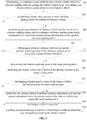
- Fig. 1 is a flow chart showing a method for parking a balance vehicle according to an exemplary embodiment.
- the method for parking a balance vehicle can be applied to a balance vehicle.
- the method for parking a balance vehicle includes the following steps.
- step 101 a determination as to whether there is a target parking point for parking the balance vehicle is made when the balance vehicle needs to be parked.
- the balance vehicle when the balance vehicle triggers turn-off, the balance vehicle may first determine whether there is a target parking point for parking the balance vehicle in order to prevent the balance vehicle from falling to the ground.
- a distance sensor of the balance vehicle can be used to determine whether there is a target parking point for parking the balance vehicle in an area within a set distance from a current position of the balance vehicle.
- a camera device provided on the balance vehicle such as a camera (wherein, the camera is rotatable within a preset angle range)
- a body motor of the balance vehicle can be used for searching for an obstacle by a touch test, and if, when the driving speed of the balance vehicle exceeds a preset speed threshold, the balance vehicle is still not able to go over the obstacle, then the obstacle can be determined as the target parking point.
- the way of determining a target parking point by using the distance sensor, camera device and body motor can be obtained from the embodiments shown in Figs 2-4 , and thus is not described here in detail.
- step 102 in the case that there is a target parking point for parking the balance vehicle, the balance vehicle is controlled to park at the target parking point.
- the balance vehicle can be controlled to be driven in a direction toward the target parking point sensed by the distance sensor to the target parking point.
- a driving route, along which the balance vehicle will be driven from the current position to the target parking point can be determined according to images captured by the camera device, and then the balance vehicle can be controlled to be driven along the driving route to the target parking point.
- the balance vehicle if the balance vehicle is blocked by an obstacle during movement within a preset area and it is determined that the balance vehicle is not able to go over the obstacle, it can be determined that the balance vehicle has reached the target parking point.
- the balance vehicle when the balance vehicle needs to be parked, the balance vehicle can automatically determine whether there is a target parking point for parking the balance vehicle in an area within a set distance from the current position, and then parks at the target parking point, which can solve the problem in related art that parking of a balance vehicle requires human's participation, thus user experience of using the balance vehicle can be improved.
- the determination as to whether there is a target parking point for parking the balance vehicle may include: determining, by a distance sensor of the balance vehicle, whether there is a reference parking point for parking the balance vehicle in an area within a set distance from the current position; determining, if it is determined by the distance sensor that there is a reference parking point for parking the balance vehicle, whether a distance between the current position and a position of the reference parking point is less than a preset distance threshold; and determining the reference parking point as the target parking point if it is determined that the distance is less than the preset distance threshold.
- the determination as to whether the distance between the current position and the position of the reference parking point is less than the preset distance threshold may include: determining, in the case where it is determined by the distance sensor that there are two or more reference parking points, distances between the balance vehicle and the two or more reference parking points, respectively; and determining whether a minimum distance among the distances for the two or more reference parking points is less than the preset distance threshold.
- controlling the balance vehicle to park at the target parking point may include: determining, by a distance sensor of the balance vehicle, a driving direction of the balance vehicle; and controlling the balance vehicle to be driven in the driving direction to the target parking point.
- the determination as to whether there is a target parking point for parking the balance vehicle may include: controlling a camera device of the balance vehicle to be rotated within a preset angle range to capture images; and determining that there is a target parking point for parking the balance vehicle if there shows a parking point for parking the balance vehicle in the images captured by the camera device.
- the method may further include: determining whether there are two or more parking points for parking the balance vehicle according to the images captured by the camera device during rotation within a preset angle range; calculating, if there are two or more parking points, complexities of driving routes along which the balance vehicle would be driven from the current position to the two or more parking points, respectively; and determining, according to the complexities of the driving routes for the two or more parking points, a parking point which corresponds to a minimum complexity among the complexities as the target parking point for parking the balance vehicle.
- controlling of the balance vehicle to park at the target parking point may include: controlling the balance vehicle to be driven along the driving route to the target parking point to park.
- the determination as to whether there is a target parking point for parking the balance vehicle may include: controlling a body motor of the balance vehicle to drive the balance vehicle to move within a preset area at a preset speed; controlling the balance vehicle in a preset speed increase manner such that the speed of the balance vehicle is increased to a preset speed threshold if the balance vehicle detects an obstacle during movement within the preset area; determining whether the balance vehicle is able to go over the obstacle if it moves at a preset speed threshold; and determining the obstacle as the target parking point for parking the balance vehicle if it is determined that the balance vehicle is not able to go over the obstacle.
- the method may further include: determining whether the balance vehicle reaches the target parking point; determining, by a balance device of the balance vehicle, whether gravity center of the balance vehicle has leaned against the target parking point upon determination that the balance vehicle reaches the target parking point; and controlling the balance vehicle to perform a posture adjustment if the gravity center of the balance vehicle has not leaned against the target parking point, and stopping the posture adjustment when the gravity center of the balance vehicle leans against the target parking point such that the balance vehicle parks at the target parking point.
- the above method provided by the present disclosure can achieve automatic parking of a balance vehicle, which can solve an problem in related art that parking a balance vehicle requires human's participation, and thus user experience of using the balance vehicle can be improved.
- Fig. 2 is a flow chart showing a method for parking a balance vehicle according to an exemplary embodiment 1.
- the embodiment utilizes the above method provided according to the embodiments of the present disclosure, and will be described by using an example, in which a distance sensor of the balance vehicle is used to achieve parking of the balance vehicle.
- the method includes the following steps.
- a distance sensor of the balance vehicle is used to determine whether there is a reference parking point for parking the balance vehicle in an area within a set distance from a current position of the balance vehicle.
- the balance vehicle may be provided with a plurality of distance sensors, of which one distance sensor can be used to determine whether there is a reference parking point in a certain direction or a range of directions.
- the balance vehicle may be provided with two distance sensors, which are used to determine whether there is a reference parking point in a forward direction and a backward direction, respectively.
- the reference parking point mentioned in the present disclosure may be a position of a target object against which the balance vehicle can lean.
- the target object maybe a wall, or may be a fixed-position object, such as a cabinet, or may be other objects for parking a balance vehicle, which are temporarily fixed in position.
- step 202 a determination as to whether there are two or more reference parking points for parking the balance vehicle is made. If it is determined that there are two or more reference parking points, then the flow goes to step 203, and if there is only one reference parking point, then the flow goes to step 204.
- the distance sensor in the balance vehicle may sense a plurality of reference parking points. For example, the distance sensor may determine there is a reference parking point at a position 3 meters away from the current position in the forward direction and there is a reference parking point at a position 4 meters away from the current position in the backward direction.
- step 203 distances between the balance vehicle and the two or more reference parking points are determined respectively, and a reference parking point which corresponds to a minimum value among the distances, is determined as the optimal reference parking point. Then, the flow goes to step 204.
- the distance sensor determines that there is a reference parking point at a position 3 meters away in the forward direction and there is a reference parking point at a position 4 meters away in the backward direction, it can be determined that the reference parking point at the position 3 meters away in the forward direction is the optimal reference parking point.
- the distance between the optimal reference parking point and the balance vehicle is compared with a preset distance threshold, in order to determine whether the optimal reference parking point can be used for parking the balance vehicle.
- step 204 a determination as to whether the distance between the current position and the position of the reference parking point is less than a preset distance threshold is made. If the distance is less than the preset distance threshold, then the flow goes to step 205, otherwise goes to step 210.
- the preset distance threshold may be obtained by recording different distances between the balance vehicle and different parking points within a certain number of parking operations for test (for example, 30 times) since a corresponding automatic parking application is installed by a user in the balance vehicle and determining a distance by which the balance vehicle can be successfully parked, and then the preset distance threshold may be stored in the balance vehicle.
- the preset distance threshold may be a default value stored in the corresponding automatic parking application, which was installed by the user.
- step 205 the reference parking point is determined as the target parking point.
- step 206 the balance vehicle is controlled to be driven in a driving direction determined by the distance sensor to the target parking point.
- the balance vehicle will be controlled to be driven in the front-right direction to the target parking point.
- step 207 upon determination that the balance vehicle reaches the target parking point, a determination as to whether gravity center of the balance vehicle has leaned against the target parking point is made by using a balance device of the balance vehicle. If the gravity center of the balance vehicle leans against the target parking point, then the flow goes to step 209, while if the gravity center of the balance vehicle has not leaned against the target parking point, then the flow goes to step 208.
- step 208 the balance vehicle is controlled to perform a posture adjustment, and the posture adjustment will be stopped upon the gravity center of the balance vehicle leans against the target parking point, after which the flow goes to step 209.
- the determination as to whether the gravity center of the balance vehicle leans against the target parking point may be made and the posture adjustment may be performed by using a balance device of the balance vehicle.
- step 209 the balance vehicle is turned off.
- step 210 a park assistance message is sent to a user terminal, in order to remind the user of assisting in parking of the balance vehicle.
- the balance vehicle may also emit sound or light or other warning signals, in order to warn persons nearby of parking the balance vehicle manually.
- a distance of a nearest parking point in the area from the current position can be exactly determined, and used for determining whether to control the balance vehicle to park at this point, which enhances probability of successful parking of the balance vehicle.
- Fig. 3 is a flow chart showing a method for parking a balance vehicle according to an exemplary embodiment 2.
- the embodiment will be schematically described by using an example in which a camera device of the balance vehicle is used for achieving parking of a balance vehicle.
- the method includes the following steps.
- step 301 the camera device of the balance vehicle is controlled to be rotated within a preset angle range to capture images.
- the camera device of the balance vehicle is rotatable within a preset angle range, and can capture images during the rotation. For example, in the case that the camera device of the balance vehicle is rotatable in an angle range of 360°, then parking points for parking the balance vehicle can be found out during rotation of the camera device within 360°.
- step 302 a determination as to whether there is a target parking point for parking the balance vehicle is made according to the images captured by the camera device during rotation within the preset angle range. If it is determined that there is a target parking point for parking the balance vehicle, the flow goes to step 303, otherwise goes to step 310.
- step 303 a determination as to whether there are two or more parking points for parking the balance vehicle is made according to the captured images during rotation of the camera device within the preset angle range. If it is determined that there are two or more parking points for the balance vehicle, then the flow goes to step 304, otherwise goes to step 306.
- step 304 complexities of driving routes along which the balance vehicle would be driven from the current position to the two or more parking points are calculated, respectively.
- step 305 according to the complexities of the driving routes for the two or more parking points, a parking point which corresponds to a minimum value among the complexities is determined as the target parking point for parking the balance vehicle.
- a parking point which corresponds to a minimum value among the complexities, can be determined as a parking point for easier parking of the balance vehicle, and therefore, the parking point with the minimum complexity can be determined as the target parking point.
- a driving route, along which the balance vehicle will be driven to a parking point A is "drive forward 3 meters, turn left 90°, then drive 2 meters", which has a complexity of 0.6
- another driving route, along which the balance vehicle will be driven to another parking point B is "drive forward 4 meters", which has a complexity of 0.3
- the parking point B will be determined as the target parking point.
- the target parking point may also be determined according to reliability of a target object at which a parking point is positioned.
- the parking point on the wall can be selected as the target parking point for the balance vehicle because the parking point on the wall may cause less negative effects on the user's daily life, while the pillar in the hall may easily block a user's movement if the user passes through.
- the level of reliability of a parking point may be preset by a user based on an empirical value.
- reliability of a reference parking point may be applied a certain weight when complexities for respective parking points are calculated.
- step 306 the balance vehicle is controlled to be driven along the driving route to the target parking point to park.
- step 307 a determination as to whether gravity center of the balance vehicle leans against the target parking point by using a balance device of the balance vehicle, when it is determined that the balance vehicle reaches the target parking point.
- step 308 the balance vehicle is controlled to perform a posture adjustment and stop the posture adjustment when the gravity center of the balance vehicle leans against the target parking point. Then, the flow goes to step 309.
- step 309 the balance vehicle is turned off.
- step 310 a park assistance message is sent to the user terminal, in order to remind the user of assisting in parking of the balance vehicle.
- the balance vehicle may also emit sound or light or other warning signals, in order to warn persons nearby of parking the balance vehicle manually.
- a parking point which is the nearest and most convenient for parking of the balance vehicle, can be determined through image processing.
- Fig. 4 is a flow chart showing a method for parking a balance vehicle according to an exemplary embodiment 3.
- the embodiment will be schematically described by using a example, in which a body motor of the balance vehicle is used to drive the balance vehicle to move within a preset area so as to achieve parking of the balance vehicle.
- the method includes the following steps.
- step 401 the body motor of the balance vehicle is controlled to drive the balance vehicle to move within a preset area at a preset speed.
- the body motor of the balance vehicle can be controlled to drive the balance vehicle to move around within a preset area at a relative slower speed, by which a touch test during the movement can be performed to determine whether there is a parking point.
- the preset area may be a relative smaller area.
- the touch test may be conducted in an area within 1 to 100 cm from the current position.
- step 402 the balance vehicle is controlled in a preset speed increase manner such that the speed of the balance vehicle is increased to a preset speed threshold if the balance vehicle detects an obstacle during movement within the preset area.
- the preset speed increase manner may be increase gradually.
- the speed can be increased by 3m/s firstly, then the balance vehicle moves forward at the increased speed, and if it still cannot able to go over an obstacle, the increased speed is increased by 2m/s, and so on.
- the increment of speed for each time may be same, or may be smaller and smaller.
- the preset speed threshold may be a speed value set by the user based on an empirical value. If the preset speed threshold is exceeded, it is possible that the balance vehicle will be damaged. Therefore, the preset speed threshold can be stored in the balance vehicle.
- step 403 a determination as to whether the balance vehicle is able to go over the obstacle if it moves at the preset speed threshold. If the balance vehicle is able to go over the obstacle, then the flow goes to step 408, but if the balance vehicle is not able to go over the obstacle, then the flow goes to step 404.
- step 404 the obstacle is determined as the target parking point for parking the balance vehicle.
- step 405 a determination as to whether gravity center of the balance vehicle leans against the target parking point by using a balance device of the balance vehicle.
- step 406 the balance vehicle is controlled to perform a posture adjustment, and stop the posture adjustment when the gravity center of the balance vehicle leans against the target parking point, after which the flow goes to step 407.
- step 407 the balance vehicle is turned off.
- step 408 a parking assistance message is sent to the user terminal, in order to remind the user of assisting in parking of the balance vehicle.
- the balance vehicle may also emit sound or light or other warning signals, in order to warn persons nearby of parking the balance vehicle manually.
- Fig. 5 is a block diagram illustrating a device for parking a balance vehicle according to an exemplary embodiment.
- the device for parking a balance vehicle includes: a first determination module 510, configured to determine whether there is a target parking point for parking the balance vehicle when the balance vehicle needs to be parked; a control module 520, configured to control, if the first determination module 510 determines that there is a target parking point for parking the balance vehicle, the balance vehicle to park at the target parking point.
- Fig. 6 is a block diagram illustrating another device for parking a balance vehicle according to an exemplary embodiment.
- the first determination module 510 may include: a first determination submodule 511, configured to determine, by a distance sensor of the balance vehicle, whether there is a reference parking point for parking the balance vehicle in an area within a set distance from the current position; a second determination submodule 512, configured to determine, if the first determination submodule 511 determines that there is a reference parking point for parking balance vehicle, whether a distance between the current position and the position of the reference parking point is less than a preset distance threshold; a third determination submodule 513, configured to determine the reference parking point as the target parking point, if the second determination submodule 512 determines that the distance is less than the preset distance threshold.
- the second determination submodule 512 may include: a distance sensor submodule 5121, configured to determine, in the case where the first determination submodule 511 determines, using the distance sensor, that there are two or more reference parking points, distances between the balance vehicle and the two or more reference parking points, respectively; a distance comparison submodule 5122, configured to determine whether a minimum distance among the distances for the two or more reference parking points determined by the distance sensor submodule 5121 is less than the preset distance threshold.
- control module 520 may include: a direction determination submodule 521, configured to determine, by using a distance sensor of the balance vehicle, a driving direction of the balance vehicle; a first control submodule 522, configured to control the balance vehicle to be driven in the driving direction determined by direction determination submodule 521 to the target parking point.
- the first determination module 510 may include: an image capture submodule 514, configured to control a camera device of the balance vehicle to be rotated within a preset angle range to capture images; an image analysis submodule 515, configured to determine that there is a target parking point for parking the balance vehicle, if there shows a parking point for parking the balance vehicle in the images captured by the image capture submodule 514 using the camera device.
- the device may further include: a number determination module 530, configured to determine whether there are parking points for parking the balance vehicle, according to the images captured by the camera device during rotation within the preset angle range under control of the image capture submodule 514; a calculating module 540, configured to calculate, if the number determination module 530 determines that there are two or more parking points, complexities of driving routes along which the balance vehicle would be driven from the current position to the two or more parking points, respectively; a second determination module 550, configured to determine, according to the complexities of driving routes for the two or more parking points calculated by the calculating module 540, a parking point which corresponds to a minimum value among the complexities as the target parking point for parking the balance vehicle.
- a number determination module 530 configured to determine whether there are parking points for parking the balance vehicle, according to the images captured by the camera device during rotation within the preset angle range under control of the image capture submodule 514
- a calculating module 540 configured to calculate, if the number determination module 530 determines that there
- control module 520 may include: a second control submodule 523, configured to control the balance vehicle to be driven along the driving route to the target parking point to park.
- Fig. 7 is a block diagram illustrating a further device for parking a balance vehicle according to an exemplary embodiment.
- the first determination module 510 may include: a drive submodule 516, configured to control a body motor of the balance vehicle to drive the balance vehicle to move within a preset area at a preset speed; a speed-up submodule 517, configured to control the balance vehicle in a preset speed increase manner such that the speed of the balance vehicle is increased to a preset speed threshold, an obstacle is detected during movement of the balance vehicle within the preset area under control of the drive submodule 516; a go-over submodule 518, configured to determine whether the balance vehicle is able to go over the obstacle if the balance vehicle moves at the preset speed threshold to which the balance vehicle is increased under control of the speed-up submodule 517; a target determination submodule 519, configured to determine the obstacle as the target parking
- the device may further include: a third determination module 560, configured to determine whether the balance vehicle reaches the target parking point; a gravity center determination module 570, configured to determine, by a balance device of the balance vehicle, whether gravity center of the balance vehicle leans against the target parking point, when the third determination module 560 determines that the balance vehicle reaches the target parking point; an adjustment module 580, configured to control, if the gravity center determination module 570 determines that the gravity center of the balance vehicle does not leans against the target parking point, the balance vehicle to perform a posture adjustment, and stop the posture adjustment when the gravity center of the balance vehicle leans against the target parking point such that the balance vehicle parks at the target parking point
- a device since it substantially corresponds to embodiments of a method, description of a certain part of the method may be referred to for description of a relevant part of the device.
- the above-described embodiments of a device are for illustrative purposes only, wherein elements described as separate components may or may not be physically separated, and components illustrated as elements may or may not be physical elements (i.e., these components may be located in the same place, or be distributed in several network elements). Part or all of the modules may be selected to realize the purposes of the scheme of this disclosure according to actual needs. Those of ordinary skill in the art may be able to understand and practice the scheme without creative efforts.
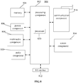
- Fig. 8 is a block diagram applicable to a device for parking a balance vehicle according to an exemplary embodiment.
- the device 800 may be a balance vehicle.
- the device 800 may include one or more of the following components: a processing component 802, a memory 804, a power component 806, a multimedia component 808, an audio component 810, an input/output (I/O) interface 812, a sensor component 814, and a communication component 816.
- a processing component 802 a memory 804, a power component 806, a multimedia component 808, an audio component 810, an input/output (I/O) interface 812, a sensor component 814, and a communication component 816.
- the processing component 802 typically controls overall operations of the device 800, such as the operations associated with display, telephone calls, data communications, camera operations, and recording operations.
- the processing component 802 may include one or more processors 820 to execute instructions to perform all or part of the steps in the above described methods.
- the processing component 802 may include one or more modules which facilitate the interaction between the processing component 802 and other components.
- the processing component 802 may include a multimedia module to facilitate the interaction between the multimedia component 808 and the processing component 802.
- the memory 804 is configured to store various types of data to support the operation of the device 800. Examples of such data may include instructions for any applications or methods operated on the device 800, contact data, phonebook data, messages, pictures, video, etc.
- the memory 804 may be implemented using any type of volatile or non-volatile memory devices, or a combination thereof, such as a static random access memory (SRAM), an electrically erasable programmable read-only memory (EEPROM), an erasable programmable read-only memory (EPROM), a programmable read-only memory (PROM), a read-only memory (ROM), a magnetic memory, a flash memory, a magnetic or optical disk.
- SRAM static random access memory
- EEPROM electrically erasable programmable read-only memory
- EPROM erasable programmable read-only memory
- PROM programmable read-only memory
- ROM read-only memory
- magnetic memory a magnetic memory
- flash memory a flash memory
- magnetic or optical disk a magnetic or
- the power component 806 provides power to various components of the device 800.
- the power component 806 may include a power management system, one or more power sources, and any other components associated with the generation, management, and distribution of power in the device 800.
- the multimedia component 808 includes a screen providing an output interface between the device 800 and the user.
- the screen may include a liquid crystal display (LCD) and a touch panel (TP). If the screen includes the touch panel, the screen may be implemented as a touch screen to receive input signals from the user.
- the touch panel includes one or more touch sensors to sense touches, swipes, and gestures on the touch panel. The touch sensors may not only sense a boundary of a touch or swipe action, but also detect a period of time and a pressure associated with the touch or swipe action.
- the multimedia component 808 includes a front camera and/or a rear camera.
- the front camera and/or the rear camera may receive an external multimedia datum while the device 800 is in an operation mode, such as a photographing mode or a video mode.
- an operation mode such as a photographing mode or a video mode.
- Each of the front camera and the rear camera may be a fixed optical lens system or have focus and optical zoom capability.
- the audio component 810 is configured to output and/or input audio signals.
- the audio component 810 includes a microphone ("MIC") configured to receive an external audio signal when the device 800 is in an operation mode, such as a call mode, a recording mode, and a voice recognition mode.
- the received audio signal may be further stored in the memory 804 or transmitted via the communication component 816.
- the audio component 810 further includes a speaker to output audio signals.
- the I/O interface 812 provides an interface between the processing component 802 and peripheral interface modules, such as a keyboard, a click wheel, buttons, and the like.
- the buttons may include, but are not limited to, a home button, a volume button, a starting button, and a locking button.
- the sensor component 814 includes one or more sensors to provide status assessments of various aspects of the device 800. For instance, the sensor component 814 may detect an open/closed status of the device 800, relative positioning of components, e.g., the display and the keypad, of the device 800, a change in position of the device 800 or a component of the device 800, a presence or absence of user contact with the device 800, an orientation or an acceleration/deceleration of the device 800, and a change in temperature of the device 800.
- the sensor component 814 may include a proximity sensor configured to detect the presence of nearby objects without any physical contact.
- the sensor component 814 may also include a light sensor, such as a CMOS or CCD image sensor, for use in imaging applications.
- the sensor component 814 may also include an accelerometer sensor, a gyroscope sensor, a magnetic sensor, a distance sensor, a pressure sensor, or a temperature sensor.
- the communication component 816 is configured to facilitate communication, wired or wirelessly, between the device 800 and other devices.
- the device 800 can access a wireless network based on a communication standard, such as Wi-Fi, 2G, or 3G, or a combination thereof.
- the communication component 816 receives a broadcast signal or broadcast associated information from an external broadcast management system via a broadcast channel.
- the communication component 816 further includes a near field communication (NFC) module to facilitate short-range communications.
- the NFC module may be implemented based on a radio frequency identification (RFID) technology, an infrared data association (IrDA) technology, an ultra-wideband (UWB) technology, a Bluetooth (BT) technology, and other technologies.
- RFID radio frequency identification
- IrDA infrared data association
- UWB ultra-wideband
- BT Bluetooth
- the device 800 may be implemented with one or more application specific integrated circuits (ASICs), digital signal processors (DSPs), digital signal processing devices (DSPDs), programmable logic devices (PLDs), field programmable gate arrays (FPGAs), controllers, micro-controllers, microprocessors, or other electronic components, for performing the above described methods.
- ASICs application specific integrated circuits
- DSPs digital signal processors
- DSPDs digital signal processing devices
- PLDs programmable logic devices
- FPGAs field programmable gate arrays
- controllers micro-controllers, microprocessors, or other electronic components, for performing the above described methods.
- non-transitory computer-readable storage medium including instructions, such as the memory 804 including instructions executable by the processor 820 in the device 800 to perform the above-described methods.
- the non-transitory computer-readable storage medium may be a ROM, a RAM, a CD-ROM, a magnetic tape, a floppy disc, an optical data storage device, and the like.
Landscapes
- Engineering & Computer Science (AREA)
- Physics & Mathematics (AREA)
- General Physics & Mathematics (AREA)
- Automation & Control Theory (AREA)
- Radar, Positioning & Navigation (AREA)
- Mechanical Engineering (AREA)
- Transportation (AREA)
- Remote Sensing (AREA)
- Aviation & Aerospace Engineering (AREA)
- Combustion & Propulsion (AREA)
- Chemical & Material Sciences (AREA)
- Multimedia (AREA)
- Theoretical Computer Science (AREA)
- Electromagnetism (AREA)
- Traffic Control Systems (AREA)
- Control Of Driving Devices And Active Controlling Of Vehicle (AREA)
Abstract
Description
- The present disclosure relates to the technical field of intelligent transportation, and more particularly, to a method and device for parking a balance vehicle.
- Balance vehicle is a new kind of short-distance transportation, which can make use of an electric motor and a balance device to realize self-balancing and going forward/backward as well as steering, and can be automatically turned off when not in use for a period of time in order to keep power from being consumed. If a balance vehicle has not leaned against an object in process of automatic turn-off, it will fall to ground due to lost of self-balancing, which may cause physical damage to the balance vehicle.
- In the related art, a balance vehicle can emit sound or light or other warning signals in process of automatic turn-off in order to warn persons nearby of the turn-off, and thereby the persons warned will take the balance vehicle in a right place manually. Since the sound or light or other warning signals emitted by the balance vehicle may disturb other persons around and the emitted sound may even lead to noise pollution when the balance vehicle is in a smaller space, user experience is thus poor; In addition, parking of the balance vehicle requires human's participation, so if nobody is in an area within a preset distance from current position of the balance vehicle or the persons warned may not get to the position of the balance vehicle in time, then the balance vehicle still may fall to the ground.
- In view of the fact in related arts, the embodiments in the present disclosure provide a method and device for parking a balance vehicle, which enables automatic movement of the balance vehicle to a parking point to achieve parking.
- According to a first aspect of embodiments in the present disclosure, a method for parking a balance vehicle is provided. The method may include: determining whether there is a target parking point for parking the balance vehicle when the balance vehicle needs to be parked; and controlling, if there is a target parking point for parking the balance vehicle, the balance vehicle to park at the target parking point.
- In an embodiment, the determining whether there is a target parking point for parking the balance vehicle may include: determining, by a distance sensor of the balance vehicle, whether there is a reference parking point for parking the balance vehicle in an area within a set distance from a current position of the balance vehicle; determining, if it is determined by the distance sensor that there is a reference parking point for parking balance vehicle, whether a distance between the current position and a position of the reference parking point is less than a preset distance threshold; and determining the reference parking point as the target parking point if it is determined that the distance is less than the preset distance threshold.
- In an embodiment, the determining whether the distance between the current position and the position of the reference parking point is less than the preset distance threshold may include: determining, in the case where it is determined by the distance sensor that there are two or more reference parking points, distances between the balance vehicle and the two or more reference parking points, respectively; and determining whether a minimum distance among the distances for the two or more reference parking points is less than the preset distance threshold.
- In an embodiment, the controlling the balance vehicle to park at the target parking point may include: determining, by a distance sensor of the balance vehicle, a driving direction of the balance vehicle; controlling the balance vehicle to be driven in the driving direction to the target parking point.
- In an embodiment, the determining whether there is a target parking point for parking the balance vehicle may include: controlling a camera device of the balance vehicle to be rotated within a preset angle range to capture images; and determining that there is a target parking point for parking the balance vehicle if there shows a parking point for parking the balance vehicle in the images captured by the camera device.
- In an embodiment, the method further includes: determining whether there are two or more parking points for parking the balance vehicle according to the images captured by the camera device during rotation within the preset angle range; calculating, if there are two or more parking points, complexities of driving routes along which the balance vehicle would be driven from a current position of the balance vehicle to the two or more parking points, respectively; and determining, according to the complexities of the driving routes for the two or more parking points, a parking point which corresponds to a minimum complexity among the complexities as the target parking point for parking the balance vehicle.
- In an embodiment, the controlling the balance vehicle to park at the target parking point may include: controlling the balance vehicle to be driven along a driving route having the minimum complexity to the target parking point to park.
- In an embodiment, the determining whether there is a target parking point for parking the balance vehicle may include: controlling a body motor of the balance vehicle to drive the balance vehicle to move within a preset area at a preset speed; controlling the balance vehicle in a preset speed increase manner such that the speed of the balance vehicle is increased to a preset speed threshold if the balance vehicle detects an obstacle during movement within the preset area; determining whether the balance vehicle is able to go over the obstacle if it moves at the preset speed threshold and determining the obstacle as the target parking point for parking the balance vehicle if it is determined that the balance vehicle is not able to go over the obstacle.
- In an embodiment, the method further may include: determining whether the balance vehicle reaches the target parking point; determining, by a balance device of the balance vehicle, whether gravity center of the balance vehicle has leaned against the target parking point upon determination that the balance vehicle reaches the target parking point; and controlling the balance vehicle to perform a posture adjustment if the gravity center of the balance vehicle has not leaned against the target parking point, and stopping the posture adjustment when the gravity center of the balance vehicle leans against the target parking point such that the balance vehicle parks at the target parking point.
- According to a second aspect of embodiments in the present disclosure, a device for parking a balance vehicle is provided. The device may include: a first determination module configured to determine whether there is a target parking point for parking the balance vehicle exists when the balance vehicle needs to be parked; a control module configured to control, if the first determination module determines that there is a target parking point for parking the balance vehicle, the balance vehicle to park at the target parking point.
- In an embodiment, the first determination module may include: a first determination submodule configured to determine, by a distance sensor of the balance vehicle, whether there is a reference parking point for parking the balance vehicle in an area within a set distance from a current position of the balance vehicle; a second determination submodule configured to determine, if the first determination submodule determines that there is a reference parking point for parking the balance vehicle, whether a distance between the current position and a position of the reference parking point is less than a preset distance threshold; and a third determination submodule configured to determine the reference parking point as the target parking point if the second determination submodule determines that the distance is less than the preset distance threshold.
- In an embodiment, the second determination submodule may include: a distance sensor submodule configured to determine, in the case where the first determination submodule determines, using the distance sensor, that there are two or more reference parking points, distances between the balance vehicle and the two or more reference parking points, respectively; and a distance comparison submodule configured to determine whether a minimum distance among the distances for the two or more reference parking points determined by the distance sensor submodule is less than the preset distance threshold.
- In an embodiment, the control module may include: a direction determination submodule configured to determine, by a distance sensor of the balance vehicle, a driving direction of the balance vehicle; a first control submodule configured to control the balance vehicle to be driven in the driving direction determined by direction determination submodule to the target parking point.
- In an embodiment, the first determination module may include: an image capture submodule configured to control a camera device of the balance vehicle to be rotated within a preset angle range to capture images; an image analysis submodule configured to determine that there is a target parking point for parking the balance vehicle if there shows a parking point for parking the balance vehicle in the images captured by the image capture submodule using the camera device.
- In an embodiment, the device may further include: a number determination module configured to determine whether there are two or more parking points for parking the balance vehicle according to the images captured by the camera device during rotation within the preset angle range under control of the image capture submodule; a calculating module, configured to calculate, if the number determination module determines that there are two or more parking points, complexities of driving routes along which the balance vehicle would be driven from a current position of the balance vehicle to the two or more parking points, respectively; a second determination module configured to determine, according to the complexities of the driving routes for the two or more parking points calculated by the calculating module, a parking point which corresponds to a minimum complexity among the complexities as the target parking point for parking the balance vehicle.
- In an embodiment, the control module may include: a second control submodule configured to control the balance vehicle to be driven along a driving route having the minimum complexity to the target parking point to park.
- In an embodiment, the first determination module may include: a drive submodule configured to control a body motor of the balance vehicle to drive the balance vehicle to move within a preset area at a preset speed; a speed-up submodule configured to control the balance vehicle in a preset speed increase manner such that the speed of the balance vehicle is increased to a preset speed threshold if an obstacle is detected during movement of the balance vehicle within the preset area under control of the drive submodule; a go-over submodule configured to determine whether the balance vehicle is able to go over the obstacle if it moves at the preset speed threshold to which the balance vehicle has increased under control of the speed-up submodule; and a target determination submodule configured to determine the obstacle as the target parking point for parking the balance vehicle if the go-over submodule determines that the balance vehicle is not able to go over the obstacle.
- In an embodiment, the device may further include: a third determination module configured to determine whether the balance vehicle reaches the target parking point; a gravity center determination module configured to determine, by a balance device of the balance vehicle, whether gravity center of the balance vehicle has leaned against the target parking point when the third determination module determines that the balance vehicle reaches the target parking point; an adjustment module, configured to control, if the gravity center determination module determines that the gravity center of the balance vehicle has not leaned against the target parking point, the balance vehicle to perform a posture adjustment, and stop the posture adjustment when the gravity center of the balance vehicle leans against the target parking point such that the balance vehicle parks at the target parking point.
- According to a third aspect of embodiments in the present disclosure, a device for controlling parking of a balance vehicle is provided. The device includes: a processor; a storage for storing instructions, which are executable by the processor; wherein, the processor is configured to: determine whether there is a target parking point for parking the balance vehicle when the balance vehicle needs to be parked; control, if there is a target parking point for parking the balance vehicle, the balance vehicle to park at the target parking point.
- The technical solutions provided by the embodiments of the present disclosure may attain at least the following beneficial effects: when the balance vehicle needs to be parked, it may automatically determine whether there is a target parking point for parking the balance vehicle in an area within a set distance from current position of the balance vehicle and then parks at the target parking point, which can solves an problem in related art that parking of a balance vehicle requires human's participation, thus user experience of using the balance vehicle can be improved.
- Furthermore, by determining, using a distance sensor of the balance vehicle, whether there is a reference parking point for parking the balance vehicle within an area of a set distance from a current position parking point, a distance of a nearest parking point in the area within the set distance from the current position can be exactly determined, and used for determining whether to control the balance vehicle to park at this point, which enhances probability of successful parking of the balance vehicle.
- By controlling a camera device of the balance vehicle to be rotated within a preset angle range, all the parking points, which are in the areas covered by images captured by the camera device during rotation, can be determined according to the captured images, and then a parking point, which is the nearest and most convenient for parking of the balance vehicle, can be determined through image processing.
- By controlling the body motor of the balance vehicle to drive the balance vehicle to move within a preset area at a preset speed, it can be determined whether there is a parking point for parking the balance vehicle in a smaller area of the area within the set distance from the current position, then automatic parking of the balance vehicle can be achieved without additional hardware supports, and thereby cost may be reduced.
- By controlling the balance vehicle to perform a posture adjustment after the balance vehicle reaches the target parking point, parking of the balance vehicle can be achieved by leaning against the target parking point, which prevents the balance vehicle from falling to the ground due to its gravity center not leaning against the target parking point.
- It is to be understood that both the forgoing general descriptions and the following detailed descriptions are exemplary and explanatory only, and are not restrictive of the present disclosure.
- The accompanying drawings, which are incorporated in and constitute a part of this specification, illustrate embodiments consistent with the disclosure and, together with the description, serve to explain the principles of the disclosure.
-
Fig. 1 is a flow chart showing a method for parking a balance vehicle according to an exemplary embodiment. -
Fig. 2 is a flow chart showing a method for parking a balance vehicle according to an exemplary embodiment 1. -
Fig. 3 is a flow chart showing a method for parking a balance vehicle according to an exemplary embodiment 2. -
Fig. 4 is a flow chart showing a method for parking a balance vehicle according to an exemplary embodiment 3. -
Fig. 5 is a block diagram illustrating a device for parking a balance vehicle according to an exemplary embodiment. -
Fig. 6 is a block diagram illustrating another device for parking a balance vehicle according to an exemplary embodiment. -
Fig. 7 is a block diagram illustrating yet another device for parking a balance vehicle according to an exemplary embodiment. -
Fig. 8 is a block diagram applicable to a device for parking a balance vehicle according to an exemplary embodiment. - Reference will now be made in detail to exemplary embodiments, examples of which are illustrated in the accompanying drawings. The following description refers to the accompanying drawings in which same numbers in different drawings represent same or similar elements unless otherwise described. The implementations set forth in the following description of exemplary embodiments do not represent all implementations consistent with the disclosure. Instead, they are merely examples of devices and methods consistent with aspects related to the disclosure as recited in the appended claims.
-
Fig. 1 is a flow chart showing a method for parking a balance vehicle according to an exemplary embodiment. The method for parking a balance vehicle can be applied to a balance vehicle. As shown inFig. 1 , the method for parking a balance vehicle includes the following steps. - In
step 101, a determination as to whether there is a target parking point for parking the balance vehicle is made when the balance vehicle needs to be parked. - In an embodiment, when the balance vehicle triggers turn-off, the balance vehicle may first determine whether there is a target parking point for parking the balance vehicle in order to prevent the balance vehicle from falling to the ground.
- In an embodiment, a distance sensor of the balance vehicle can be used to determine whether there is a target parking point for parking the balance vehicle in an area within a set distance from a current position of the balance vehicle. In another embodiment, a camera device provided on the balance vehicle, such as a camera (wherein, the camera is rotatable within a preset angle range), can be used to determine whether there is a target parking point for parking the balance vehicle. In a further embodiment, a body motor of the balance vehicle can be used for searching for an obstacle by a touch test, and if, when the driving speed of the balance vehicle exceeds a preset speed threshold, the balance vehicle is still not able to go over the obstacle, then the obstacle can be determined as the target parking point. The way of determining a target parking point by using the distance sensor, camera device and body motor can be obtained from the embodiments shown in
Figs 2-4 , and thus is not described here in detail. - In
step 102, in the case that there is a target parking point for parking the balance vehicle, the balance vehicle is controlled to park at the target parking point. - In an embodiment, the balance vehicle can be controlled to be driven in a direction toward the target parking point sensed by the distance sensor to the target parking point. In another embodiment, a driving route, along which the balance vehicle will be driven from the current position to the target parking point, can be determined according to images captured by the camera device, and then the balance vehicle can be controlled to be driven along the driving route to the target parking point. In a further embodiment, if the balance vehicle is blocked by an obstacle during movement within a preset area and it is determined that the balance vehicle is not able to go over the obstacle, it can be determined that the balance vehicle has reached the target parking point.
- In this embodiment, when the balance vehicle needs to be parked, the balance vehicle can automatically determine whether there is a target parking point for parking the balance vehicle in an area within a set distance from the current position, and then parks at the target parking point, which can solve the problem in related art that parking of a balance vehicle requires human's participation, thus user experience of using the balance vehicle can be improved.
- In an embodiment, the determination as to whether there is a target parking point for parking the balance vehicle may include: determining, by a distance sensor of the balance vehicle, whether there is a reference parking point for parking the balance vehicle in an area within a set distance from the current position; determining, if it is determined by the distance sensor that there is a reference parking point for parking the balance vehicle, whether a distance between the current position and a position of the reference parking point is less than a preset distance threshold; and determining the reference parking point as the target parking point if it is determined that the distance is less than the preset distance threshold.
- In an embodiment, the determination as to whether the distance between the current position and the position of the reference parking point is less than the preset distance threshold may include: determining, in the case where it is determined by the distance sensor that there are two or more reference parking points, distances between the balance vehicle and the two or more reference parking points, respectively; and determining whether a minimum distance among the distances for the two or more reference parking points is less than the preset distance threshold.
- In an embodiment, the controlling the balance vehicle to park at the target parking point may include: determining, by a distance sensor of the balance vehicle, a driving direction of the balance vehicle; and controlling the balance vehicle to be driven in the driving direction to the target parking point.
- In an embodiment, the determination as to whether there is a target parking point for parking the balance vehicle may include: controlling a camera device of the balance vehicle to be rotated within a preset angle range to capture images; and determining that there is a target parking point for parking the balance vehicle if there shows a parking point for parking the balance vehicle in the images captured by the camera device.
- In an embodiment, the method may further include: determining whether there are two or more parking points for parking the balance vehicle according to the images captured by the camera device during rotation within a preset angle range; calculating, if there are two or more parking points, complexities of driving routes along which the balance vehicle would be driven from the current position to the two or more parking points, respectively; and determining, according to the complexities of the driving routes for the two or more parking points, a parking point which corresponds to a minimum complexity among the complexities as the target parking point for parking the balance vehicle.
- In an embodiment, the controlling of the balance vehicle to park at the target parking point may include: controlling the balance vehicle to be driven along the driving route to the target parking point to park.
- In an embodiment, the determination as to whether there is a target parking point for parking the balance vehicle may include: controlling a body motor of the balance vehicle to drive the balance vehicle to move within a preset area at a preset speed; controlling the balance vehicle in a preset speed increase manner such that the speed of the balance vehicle is increased to a preset speed threshold if the balance vehicle detects an obstacle during movement within the preset area; determining whether the balance vehicle is able to go over the obstacle if it moves at a preset speed threshold; and determining the obstacle as the target parking point for parking the balance vehicle if it is determined that the balance vehicle is not able to go over the obstacle.
- In an embodiment, the method may further include: determining whether the balance vehicle reaches the target parking point; determining, by a balance device of the balance vehicle, whether gravity center of the balance vehicle has leaned against the target parking point upon determination that the balance vehicle reaches the target parking point; and controlling the balance vehicle to perform a posture adjustment if the gravity center of the balance vehicle has not leaned against the target parking point, and stopping the posture adjustment when the gravity center of the balance vehicle leans against the target parking point such that the balance vehicle parks at the target parking point.
- Regarding details about how to park a balance vehicle, please see the following embodiments.
- So far, the above method provided by the present disclosure can achieve automatic parking of a balance vehicle, which can solve an problem in related art that parking a balance vehicle requires human's participation, and thus user experience of using the balance vehicle can be improved.
- The following particular embodiments are provided to illustrate the technical solutions of the embodiments of the present disclosure.
-
Fig. 2 is a flow chart showing a method for parking a balance vehicle according to an exemplary embodiment 1. The embodiment utilizes the above method provided according to the embodiments of the present disclosure, and will be described by using an example, in which a distance sensor of the balance vehicle is used to achieve parking of the balance vehicle. As shown inFig. 2 , the method includes the following steps. - In
step 201, a distance sensor of the balance vehicle is used to determine whether there is a reference parking point for parking the balance vehicle in an area within a set distance from a current position of the balance vehicle. - In an embodiment, the balance vehicle may be provided with a plurality of distance sensors, of which one distance sensor can be used to determine whether there is a reference parking point in a certain direction or a range of directions. For example, the balance vehicle may be provided with two distance sensors, which are used to determine whether there is a reference parking point in a forward direction and a backward direction, respectively.
- In an embodiment, the reference parking point mentioned in the present disclosure may be a position of a target object against which the balance vehicle can lean. In an embodiment, the target object maybe a wall, or may be a fixed-position object, such as a cabinet, or may be other objects for parking a balance vehicle, which are temporarily fixed in position.
- In
step 202, a determination as to whether there are two or more reference parking points for parking the balance vehicle is made. If it is determined that there are two or more reference parking points, then the flow goes to step 203, and if there is only one reference parking point, then the flow goes to step 204. - In an embodiment, the distance sensor in the balance vehicle may sense a plurality of reference parking points. For example, the distance sensor may determine there is a reference parking point at a position 3 meters away from the current position in the forward direction and there is a reference parking point at a position 4 meters away from the current position in the backward direction.
- In
step 203, distances between the balance vehicle and the two or more reference parking points are determined respectively, and a reference parking point which corresponds to a minimum value among the distances, is determined as the optimal reference parking point. Then, the flow goes to step 204. - For example, in the case where the distance sensor determines that there is a reference parking point at a position 3 meters away in the forward direction and there is a reference parking point at a position 4 meters away in the backward direction, it can be determined that the reference parking point at the position 3 meters away in the forward direction is the optimal reference parking point. The distance between the optimal reference parking point and the balance vehicle is compared with a preset distance threshold, in order to determine whether the optimal reference parking point can be used for parking the balance vehicle.
- In
step 204, a determination as to whether the distance between the current position and the position of the reference parking point is less than a preset distance threshold is made. If the distance is less than the preset distance threshold, then the flow goes to step 205, otherwise goes to step 210. - In an embodiment, the preset distance threshold may be obtained by recording different distances between the balance vehicle and different parking points within a certain number of parking operations for test (for example, 30 times) since a corresponding automatic parking application is installed by a user in the balance vehicle and determining a distance by which the balance vehicle can be successfully parked, and then the preset distance threshold may be stored in the balance vehicle.
- In an embodiment, the preset distance threshold may be a default value stored in the corresponding automatic parking application, which was installed by the user.
- In
step 205, the reference parking point is determined as the target parking point. - In
step 206, the balance vehicle is controlled to be driven in a driving direction determined by the distance sensor to the target parking point. - For example, if it is determined that the target parking point is positioned in front of right side of the current position, then it can be determined that the driving direction of the balance vehicle is in front-right direction, and the balance vehicle will be controlled to be driven in the front-right direction to the target parking point.
- In
step 207, upon determination that the balance vehicle reaches the target parking point, a determination as to whether gravity center of the balance vehicle has leaned against the target parking point is made by using a balance device of the balance vehicle. If the gravity center of the balance vehicle leans against the target parking point, then the flow goes to step 209, while if the gravity center of the balance vehicle has not leaned against the target parking point, then the flow goes to step 208. - In
step 208, the balance vehicle is controlled to perform a posture adjustment, and the posture adjustment will be stopped upon the gravity center of the balance vehicle leans against the target parking point, after which the flow goes to step 209. - In an embodiment, the determination as to whether the gravity center of the balance vehicle leans against the target parking point may be made and the posture adjustment may be performed by using a balance device of the balance vehicle.
- In
step 209, the balance vehicle is turned off. - In
step 210, a park assistance message is sent to a user terminal, in order to remind the user of assisting in parking of the balance vehicle. - In an embodiment, the balance vehicle may also emit sound or light or other warning signals, in order to warn persons nearby of parking the balance vehicle manually.
- In this embodiment, by determining, using a distance sensor of the balance vehicle, whether there is a reference parking point for parking the balance vehicle in an area within a set distance from a current position of the balance vehicle, a distance of a nearest parking point in the area from the current position can be exactly determined, and used for determining whether to control the balance vehicle to park at this point, which enhances probability of successful parking of the balance vehicle.
-
Fig. 3 is a flow chart showing a method for parking a balance vehicle according to an exemplary embodiment 2. The embodiment will be schematically described by using an example in which a camera device of the balance vehicle is used for achieving parking of a balance vehicle. As shown inFigure 3 , the method includes the following steps. - In
step 301, the camera device of the balance vehicle is controlled to be rotated within a preset angle range to capture images. - In an embodiment, the camera device of the balance vehicle is rotatable within a preset angle range, and can capture images during the rotation. For example, in the case that the camera device of the balance vehicle is rotatable in an angle range of 360°, then parking points for parking the balance vehicle can be found out during rotation of the camera device within 360°.
- In
step 302, a determination as to whether there is a target parking point for parking the balance vehicle is made according to the images captured by the camera device during rotation within the preset angle range. If it is determined that there is a target parking point for parking the balance vehicle, the flow goes to step 303, otherwise goes to step 310. - In
step 303, a determination as to whether there are two or more parking points for parking the balance vehicle is made according to the captured images during rotation of the camera device within the preset angle range. If it is determined that there are two or more parking points for the balance vehicle, then the flow goes to step 304, otherwise goes to step 306. - In
step 304, complexities of driving routes along which the balance vehicle would be driven from the current position to the two or more parking points are calculated, respectively. - In
step 305, according to the complexities of the driving routes for the two or more parking points, a parking point which corresponds to a minimum value among the complexities is determined as the target parking point for parking the balance vehicle. - In an embodiment, a parking point, which corresponds to a minimum value among the complexities, can be determined as a parking point for easier parking of the balance vehicle, and therefore, the parking point with the minimum complexity can be determined as the target parking point. For example, in the case where a driving route, along which the balance vehicle will be driven to a parking point A, is "drive forward 3 meters, turn left 90°, then drive 2 meters", which has a complexity of 0.6, and another driving route, along which the balance vehicle will be driven to another parking point B, is "drive forward 4 meters", which has a complexity of 0.3, the parking point B will be determined as the target parking point.
- In another embodiment, the target parking point may also be determined according to reliability of a target object at which a parking point is positioned. For example, in the case where two parking points are determined according to the captured images, and one of them is a parking point on a wall, and the other one is a park point on a pillar in a hall, the parking point on the wall can be selected as the target parking point for the balance vehicle because the parking point on the wall may cause less negative effects on the user's daily life, while the pillar in the hall may easily block a user's movement if the user passes through. The level of reliability of a parking point may be preset by a user based on an empirical value.
- In an embodiment, reliability of a reference parking point may be applied a certain weight when complexities for respective parking points are calculated. The particular value of the weight can be preset by a user based on an empirical value. For example, in the case where the driving route, along which the balance vehicle will be driven to a parking point A, is "drive forward 3 meters, turn left 90°, then go ahead 2 meters", which has a complexity of 0.6, and the parking point is a wall, which has a reliability of 0.8, while another driving route, along which the balance vehicle will be driven to another parking point B, is "drive forward 4 meters", which has a complexity of 0.3, and the parking point is on a cabinet, which has a reliability 0.6, if each reliability is applied with a weight of -0.2, then the complexity for the parking point A is 0.6+(-0.2)*0.8 = 0.44, and the complexity for the parking point B is 0.3+(-0.2)*0.6 = 0.18, and hence it can be determined that the parking point B is the target parking point.
- In
step 306, the balance vehicle is controlled to be driven along the driving route to the target parking point to park. - In
step 307, a determination as to whether gravity center of the balance vehicle leans against the target parking point by using a balance device of the balance vehicle, when it is determined that the balance vehicle reaches the target parking point. - In step 308, the balance vehicle is controlled to perform a posture adjustment and stop the posture adjustment when the gravity center of the balance vehicle leans against the target parking point. Then, the flow goes to step 309.
- In
step 309, the balance vehicle is turned off. - In
step 310, a park assistance message is sent to the user terminal, in order to remind the user of assisting in parking of the balance vehicle. - In an embodiment, the balance vehicle may also emit sound or light or other warning signals, in order to warn persons nearby of parking the balance vehicle manually.
- In this embodiment, by controlling a camera device of the balance vehicle to be rotated within a preset angle range, all the parking points, which are in the area covered by images captured by the camera device during rotation, can be determined according to the captured images, and then a parking point, which is the nearest and most convenient for parking of the balance vehicle, can be determined through image processing.
-
Fig. 4 is a flow chart showing a method for parking a balance vehicle according to an exemplary embodiment 3. The embodiment will be schematically described by using a example, in which a body motor of the balance vehicle is used to drive the balance vehicle to move within a preset area so as to achieve parking of the balance vehicle. As shown inFig. 4 , the method includes the following steps. - In
step 401, the body motor of the balance vehicle is controlled to drive the balance vehicle to move within a preset area at a preset speed. - In an embodiment, the body motor of the balance vehicle can be controlled to drive the balance vehicle to move around within a preset area at a relative slower speed, by which a touch test during the movement can be performed to determine whether there is a parking point. In an embodiment, the preset area may be a relative smaller area. For example, the touch test may be conducted in an area within 1 to 100 cm from the current position.
- In
step 402, the balance vehicle is controlled in a preset speed increase manner such that the speed of the balance vehicle is increased to a preset speed threshold if the balance vehicle detects an obstacle during movement within the preset area. - In an embodiment, the preset speed increase manner may be increase gradually. For example, the speed can be increased by 3m/s firstly, then the balance vehicle moves forward at the increased speed, and if it still cannot able to go over an obstacle, the increased speed is increased by 2m/s, and so on. The increment of speed for each time may be same, or may be smaller and smaller.
- In an embodiment, the preset speed threshold may be a speed value set by the user based on an empirical value. If the preset speed threshold is exceeded, it is possible that the balance vehicle will be damaged. Therefore, the preset speed threshold can be stored in the balance vehicle.
- In
step 403, a determination as to whether the balance vehicle is able to go over the obstacle if it moves at the preset speed threshold. If the balance vehicle is able to go over the obstacle, then the flow goes to step 408, but if the balance vehicle is not able to go over the obstacle, then the flow goes to step 404. - In
step 404, the obstacle is determined as the target parking point for parking the balance vehicle. - In
step 405, a determination as to whether gravity center of the balance vehicle leans against the target parking point by using a balance device of the balance vehicle. - In
step 406, the balance vehicle is controlled to perform a posture adjustment, and stop the posture adjustment when the gravity center of the balance vehicle leans against the target parking point, after which the flow goes to step 407. - In
step 407, the balance vehicle is turned off. - In
step 408, a parking assistance message is sent to the user terminal, in order to remind the user of assisting in parking of the balance vehicle. - In an embodiment, the balance vehicle may also emit sound or light or other warning signals, in order to warn persons nearby of parking the balance vehicle manually.
- In this embodiment, by controlling the body motor of the balance vehicle to drive the balance vehicle to move within a preset area at a preset speed, it can be determined whether there is a parking point for parking the balance vehicle within a smaller area in the area within a set distance from the current position, automatic parking of the balance vehicle can be achieved without additional hardware supports, and thereby cost may be reduced.
- It should be understood by those skilled in the art that, the technical solutions described with respect to
Fig. 2 ,Fig. 3 andFig. 4 of the present disclosure can be applied to a same device or a same balance vehicle at the same time. The technical solutions can also be used in combination in order to achieve safe, automatic parking of a balance vehicle. -
Fig. 5 is a block diagram illustrating a device for parking a balance vehicle according to an exemplary embodiment. As shown inFig. 5 , the device for parking a balance vehicle includes: afirst determination module 510, configured to determine whether there is a target parking point for parking the balance vehicle when the balance vehicle needs to be parked; acontrol module 520, configured to control, if thefirst determination module 510 determines that there is a target parking point for parking the balance vehicle, the balance vehicle to park at the target parking point. -
Fig. 6 is a block diagram illustrating another device for parking a balance vehicle according to an exemplary embodiment. As shown inFig. 6 , based on the embodiment shown inFig. 5 above, in an embodiment, thefirst determination module 510 may include: afirst determination submodule 511, configured to determine, by a distance sensor of the balance vehicle, whether there is a reference parking point for parking the balance vehicle in an area within a set distance from the current position; a second determination submodule 512, configured to determine, if thefirst determination submodule 511 determines that there is a reference parking point for parking balance vehicle, whether a distance between the current position and the position of the reference parking point is less than a preset distance threshold; a third determination submodule 513, configured to determine the reference parking point as the target parking point, if the second determination submodule 512 determines that the distance is less than the preset distance threshold. - In an embodiment, the second determination submodule 512 may include: a
distance sensor submodule 5121, configured to determine, in the case where thefirst determination submodule 511 determines, using the distance sensor, that there are two or more reference parking points, distances between the balance vehicle and the two or more reference parking points, respectively; adistance comparison submodule 5122, configured to determine whether a minimum distance among the distances for the two or more reference parking points determined by thedistance sensor submodule 5121 is less than the preset distance threshold. - In an embodiment, the
control module 520 may include: adirection determination submodule 521, configured to determine, by using a distance sensor of the balance vehicle, a driving direction of the balance vehicle; afirst control submodule 522, configured to control the balance vehicle to be driven in the driving direction determined bydirection determination submodule 521 to the target parking point. - In an embodiment, the
first determination module 510 may include: animage capture submodule 514, configured to control a camera device of the balance vehicle to be rotated within a preset angle range to capture images; animage analysis submodule 515, configured to determine that there is a target parking point for parking the balance vehicle, if there shows a parking point for parking the balance vehicle in the images captured by theimage capture submodule 514 using the camera device. - In an embodiment, the device may further include: a number determination module 530, configured to determine whether there are parking points for parking the balance vehicle, according to the images captured by the camera device during rotation within the preset angle range under control of the
image capture submodule 514; a calculatingmodule 540, configured to calculate, if the number determination module 530 determines that there are two or more parking points, complexities of driving routes along which the balance vehicle would be driven from the current position to the two or more parking points, respectively; asecond determination module 550, configured to determine, according to the complexities of driving routes for the two or more parking points calculated by the calculatingmodule 540, a parking point which corresponds to a minimum value among the complexities as the target parking point for parking the balance vehicle. - In an embodiment, the
control module 520 may include: asecond control submodule 523, configured to control the balance vehicle to be driven along the driving route to the target parking point to park. -
Fig. 7 is a block diagram illustrating a further device for parking a balance vehicle according to an exemplary embodiment. As shown inFig. 7 , based on the embodiments shown inFig. 5 or fig. 6 above, in an embodiment, thefirst determination module 510 may include: adrive submodule 516, configured to control a body motor of the balance vehicle to drive the balance vehicle to move within a preset area at a preset speed; a speed-up submodule 517, configured to control the balance vehicle in a preset speed increase manner such that the speed of the balance vehicle is increased to a preset speed threshold, an obstacle is detected during movement of the balance vehicle within the preset area under control of thedrive submodule 516; a go-over submodule 518, configured to determine whether the balance vehicle is able to go over the obstacle if the balance vehicle moves at the preset speed threshold to which the balance vehicle is increased under control of the speed-up submodule 517; atarget determination submodule 519, configured to determine the obstacle as the target parking point for parking the balance vehicle, if the go-over submodule 518 determines that the balance vehicle is not able to go over the obstacle. - In an embodiment, the device may further include: a
third determination module 560, configured to determine whether the balance vehicle reaches the target parking point; a gravitycenter determination module 570, configured to determine, by a balance device of the balance vehicle, whether gravity center of the balance vehicle leans against the target parking point, when thethird determination module 560 determines that the balance vehicle reaches the target parking point; anadjustment module 580, configured to control, if the gravitycenter determination module 570 determines that the gravity center of the balance vehicle does not leans against the target parking point, the balance vehicle to perform a posture adjustment, and stop the posture adjustment when the gravity center of the balance vehicle leans against the target parking point such that the balance vehicle parks at the target parking point - The implementation procedures of functions and features of respective modules of the device are same as those in respective steps of the above methods, and thus will be not repeated here.
- For embodiments of a device, since it substantially corresponds to embodiments of a method, description of a certain part of the method may be referred to for description of a relevant part of the device. The above-described embodiments of a device are for illustrative purposes only, wherein elements described as separate components may or may not be physically separated, and components illustrated as elements may or may not be physical elements (i.e., these components may be located in the same place, or be distributed in several network elements). Part or all of the modules may be selected to realize the purposes of the scheme of this disclosure according to actual needs. Those of ordinary skill in the art may be able to understand and practice the scheme without creative efforts.
-
Fig. 8 is a block diagram applicable to a device for parking a balance vehicle according to an exemplary embodiment. For example, thedevice 800 may be a balance vehicle. - Referring to
Fig. 8 , thedevice 800 may include one or more of the following components: aprocessing component 802, amemory 804, apower component 806, amultimedia component 808, anaudio component 810, an input/output (I/O)interface 812, asensor component 814, and acommunication component 816. - The
processing component 802 typically controls overall operations of thedevice 800, such as the operations associated with display, telephone calls, data communications, camera operations, and recording operations. Theprocessing component 802 may include one ormore processors 820 to execute instructions to perform all or part of the steps in the above described methods. Moreover, theprocessing component 802 may include one or more modules which facilitate the interaction between theprocessing component 802 and other components. For instance, theprocessing component 802 may include a multimedia module to facilitate the interaction between themultimedia component 808 and theprocessing component 802. - The
memory 804 is configured to store various types of data to support the operation of thedevice 800. Examples of such data may include instructions for any applications or methods operated on thedevice 800, contact data, phonebook data, messages, pictures, video, etc. Thememory 804 may be implemented using any type of volatile or non-volatile memory devices, or a combination thereof, such as a static random access memory (SRAM), an electrically erasable programmable read-only memory (EEPROM), an erasable programmable read-only memory (EPROM), a programmable read-only memory (PROM), a read-only memory (ROM), a magnetic memory, a flash memory, a magnetic or optical disk. - The
power component 806 provides power to various components of thedevice 800. Thepower component 806 may include a power management system, one or more power sources, and any other components associated with the generation, management, and distribution of power in thedevice 800. - The
multimedia component 808 includes a screen providing an output interface between thedevice 800 and the user. In some embodiments, the screen may include a liquid crystal display (LCD) and a touch panel (TP). If the screen includes the touch panel, the screen may be implemented as a touch screen to receive input signals from the user. The touch panel includes one or more touch sensors to sense touches, swipes, and gestures on the touch panel. The touch sensors may not only sense a boundary of a touch or swipe action, but also detect a period of time and a pressure associated with the touch or swipe action. In some embodiments, themultimedia component 808 includes a front camera and/or a rear camera. The front camera and/or the rear camera may receive an external multimedia datum while thedevice 800 is in an operation mode, such as a photographing mode or a video mode. Each of the front camera and the rear camera may be a fixed optical lens system or have focus and optical zoom capability. - The
audio component 810 is configured to output and/or input audio signals. For example, theaudio component 810 includes a microphone ("MIC") configured to receive an external audio signal when thedevice 800 is in an operation mode, such as a call mode, a recording mode, and a voice recognition mode. The received audio signal may be further stored in thememory 804 or transmitted via thecommunication component 816. In some embodiments, theaudio component 810 further includes a speaker to output audio signals. - The I/
O interface 812 provides an interface between theprocessing component 802 and peripheral interface modules, such as a keyboard, a click wheel, buttons, and the like. The buttons may include, but are not limited to, a home button, a volume button, a starting button, and a locking button. - The
sensor component 814 includes one or more sensors to provide status assessments of various aspects of thedevice 800. For instance, thesensor component 814 may detect an open/closed status of thedevice 800, relative positioning of components, e.g., the display and the keypad, of thedevice 800, a change in position of thedevice 800 or a component of thedevice 800, a presence or absence of user contact with thedevice 800, an orientation or an acceleration/deceleration of thedevice 800, and a change in temperature of thedevice 800. Thesensor component 814 may include a proximity sensor configured to detect the presence of nearby objects without any physical contact. Thesensor component 814 may also include a light sensor, such as a CMOS or CCD image sensor, for use in imaging applications. In some embodiments, thesensor component 814 may also include an accelerometer sensor, a gyroscope sensor, a magnetic sensor, a distance sensor, a pressure sensor, or a temperature sensor. - The
communication component 816 is configured to facilitate communication, wired or wirelessly, between thedevice 800 and other devices. Thedevice 800 can access a wireless network based on a communication standard, such as Wi-Fi, 2G, or 3G, or a combination thereof. In one exemplary embodiment, thecommunication component 816 receives a broadcast signal or broadcast associated information from an external broadcast management system via a broadcast channel. In one exemplary embodiment, thecommunication component 816 further includes a near field communication (NFC) module to facilitate short-range communications. For example, the NFC module may be implemented based on a radio frequency identification (RFID) technology, an infrared data association (IrDA) technology, an ultra-wideband (UWB) technology, a Bluetooth (BT) technology, and other technologies. - In exemplary embodiments, the
device 800 may be implemented with one or more application specific integrated circuits (ASICs), digital signal processors (DSPs), digital signal processing devices (DSPDs), programmable logic devices (PLDs), field programmable gate arrays (FPGAs), controllers, micro-controllers, microprocessors, or other electronic components, for performing the above described methods. - In exemplary embodiments, there is also provided a non-transitory computer-readable storage medium including instructions, such as the
memory 804 including instructions executable by theprocessor 820 in thedevice 800 to perform the above-described methods. For example, the non-transitory computer-readable storage medium may be a ROM, a RAM, a CD-ROM, a magnetic tape, a floppy disc, an optical data storage device, and the like. - Other embodiments of the invention will be apparent to those skilled in the art from consideration of the specification and practice of the invention disclosed here. This application is intended to cover any variations, uses, or adaptations of the invention following the general principles thereof and including such departures from the present disclosure as come within known or customary practice in the art. The specification and embodiments are merely considered to be exemplary and the substantive scope of the disclosure is limited only by the appended claims.
- It should be understood that the disclosure is not limited to the precise structure as described above and shown in the figures, but can have various modification and alternations without departing from the scope of the disclosure. The scope of the disclosure is limited only by the appended claims.
Claims (13)
- A method for parking a balance vehicle, characterized by comprising:determining (101) whether there is a target parking point for parking the balance vehicle when the balance vehicle needs to be parked; andcontrolling (102), if there is a target parking point for parking the balance vehicle, the balance vehicle to park at the target parking point.
- The method of claim 1, wherein the determining whether there is a target parking point for parking the balance vehicle comprises:determining (201), by a distance sensor of the balance vehicle, whether there is a reference parking point for parking the balance vehicle in an area within a set distance from a current position of the balance vehicle;determining (204), if it is determined by the distance sensor that there is a reference parking point for parking balance vehicle, whether a distance between the current position and a position of the reference parking point is less than a preset distance threshold; anddetermining (205) the reference parking point as the target parking point if it is determined that the distance is less than the preset distance threshold.
- The method of claim 2, wherein the determining whether the distance between the current position and the position of the reference parking point is less than the preset distance threshold comprises:determining (203), in the case where it is determined by the distance sensor that there are two or more reference parking points, distances between the balance vehicle and the two or more reference parking points, respectively; anddetermining (203) whether a minimum distance among the distances for the two or more reference parking points is less than the preset distance threshold.
- The method of claim 1, wherein the controlling the balance vehicle to park at the target parking point comprises:determining, by a distance sensor of the balance vehicle, a driving direction of the balance vehicle; andcontrolling (206) the balance vehicle to be driven in the driving direction to the target parking point.
- The method of claim 1, wherein the determining whether there is a target parking point for parking the balance vehicle comprises:controlling (301) a camera device of the balance vehicle to be rotated within a preset angle range to capture images; anddetermining (302) that there is a target parking point for parking the balance vehicle if there shows a parking point for parking the balance vehicle in the images captured by the camera device.
- The method of claim 5, further comprising:determining (303) whether there are two or more parking points for parking the balance vehicle according to the images captured by the camera device during rotation within the preset angle range;calculating (304), if there are two or more parking points, complexities of driving routes along which the balance vehicle would be driven from a current position of the balance vehicle to the two or more parking points, respectively; anddetermining (305), according to the complexities of the driving routes for the two or more parking points, a parking point which corresponds to a minimum complexity among the complexities as the target parking point for parking the balance vehicle.
- The method of claim 6, wherein the controlling the balance vehicle to park at the target parking point comprises:controlling (306) the balance vehicle to be driven along a driving route having the minimum complexity to the target parking point to park.
- The method of claim 1, wherein the determining whether there is a target parking point for parking the balance vehicle comprises:controlling (401) a body motor of the balance vehicle to drive the balance vehicle to move within a preset area at a preset speed;controlling (402) the balance vehicle in a preset speed increase manner such that the speed of the balance vehicle is increased to a preset speed threshold if the balance vehicle detects an obstacle during movement within the preset area;determining (403) whether the balance vehicle is able to go over the obstacle if it moves at the preset speed threshold; anddetermining (404) the obstacle as the target parking point for parking the balance vehicle if it is determined that the balance vehicle is not able to go over the obstacle.
- The method of claim 1, further comprising:determining whether the balance vehicle reaches the target parking point;determining (207, 307, 405), by a balance device of the balance vehicle, whether gravity center of the balance vehicle has leaned against the target parking point upon determination that the balance vehicle reaches the target parking point; andcontrolling (208, 308, 406) the balance vehicle to perform a posture adjustment if the gravity center of the balance vehicle has not leaned against the target parking point, and stopping the posture adjustment when the gravity center of the balance vehicle leans against the target parking point such that the balance vehicle parks at the target parking point.
- A device for parking a balance vehicle, comprising components for performing a method for controlling parking of a balance vehicle according to any one of claims 1 to 9.
- A device for controlling parking of a balance vehicle, characterized by comprising:a processor;a storage for storing instructions, which are executable by the processor;wherein the processor is configured to:determine whether there is a target parking point for parking the balance vehicle, when the balance vehicle needs to be parked;control, if there is a target parking point for parking the balance vehicle, the balance vehicle to park at the target parking point.
- A computer program including instructions for executing the steps of a method for controlling parking of a balance vehicle according to any one of claims 1 to 9 when said program is executed by a computer.
- A recording medium readable by a computer and having recorded thereon a computer program including instructions for executing the steps of a method for controlling parking of a balance vehicle according to any one of claims 1 to 9.
Applications Claiming Priority (1)
| Application Number | Priority Date | Filing Date | Title |
|---|---|---|---|
| CN201610187664.2A CN105810007B (en) | 2016-03-29 | 2016-03-29 | Balance car parking method and device |
Publications (1)
| Publication Number | Publication Date |
|---|---|
| EP3226096A1 true EP3226096A1 (en) | 2017-10-04 |
Family
ID=56454957
Family Applications (1)
| Application Number | Title | Priority Date | Filing Date |
|---|---|---|---|
| EP16196306.1A Ceased EP3226096A1 (en) | 2016-03-29 | 2016-10-28 | Method and device for parking a balance vehicle |
Country Status (4)
| Country | Link |
|---|---|
| US (1) | US10336319B2 (en) |
| EP (1) | EP3226096A1 (en) |
| CN (1) | CN105810007B (en) |
| WO (1) | WO2017166550A1 (en) |
Cited By (3)
| Publication number | Priority date | Publication date | Assignee | Title |
|---|---|---|---|---|
| EP3381757A1 (en) * | 2017-03-30 | 2018-10-03 | Valeo Schalter und Sensoren GmbH | Evaluation of the complexity of parking a vehicle |
| EP3287747B1 (en) * | 2016-08-23 | 2020-12-30 | Beijing Xiaomi Mobile Software Co., Ltd. | Method and apparatus for controlling a balance car |
| CN113246969A (en) * | 2018-12-25 | 2021-08-13 | 西安艾润物联网技术服务有限责任公司 | Automatic parking method, device and readable storage medium |
Families Citing this family (16)
| Publication number | Priority date | Publication date | Assignee | Title |
|---|---|---|---|---|
| CN105721834B (en) * | 2016-03-29 | 2018-12-25 | 北京小米移动软件有限公司 | Control the method and device that balance car is stopped |
| CN105810007B (en) * | 2016-03-29 | 2020-07-03 | 北京小米移动软件有限公司 | Balance car parking method and device |
| WO2018039908A1 (en) * | 2016-08-30 | 2018-03-08 | 尚艳燕 | Method and device for automatically parking balancing vehicle |
| WO2018039909A1 (en) * | 2016-08-30 | 2018-03-08 | 尚艳燕 | Automatic parking method and apparatus for balance vehicle in narrow space |
| US20180335773A1 (en) * | 2017-05-16 | 2018-11-22 | Yi Xie | Balancing board |
| CN107992091B (en) * | 2017-10-31 | 2021-10-12 | 深圳市博鑫创科科技有限公司 | Balance vehicle following method and system based on signal intensity |
| CN108121352A (en) * | 2017-10-31 | 2018-06-05 | 深圳市博鑫创科科技有限公司 | The method and system that a kind of balance car is stopped automatically |
| CN108121341B (en) * | 2017-10-31 | 2021-04-16 | 深圳市博鑫创科科技有限公司 | Automatic parking method and system for balance car fleet |
| CN108121944A (en) * | 2017-10-31 | 2018-06-05 | 深圳市博鑫创科科技有限公司 | A kind of automatic parking scheme of balance car based on camera and system |
| CN108121340B (en) * | 2017-10-31 | 2021-09-03 | 深圳市博鑫创科科技有限公司 | Two-dimensional code-based balance car automatic parking method and system |
| CN110789519B (en) * | 2018-08-02 | 2023-03-03 | 奥迪股份公司 | Method, device, equipment and storage medium for obtaining parking position of vehicles |
| JP6767443B2 (en) * | 2018-09-07 | 2020-10-14 | 本田技研工業株式会社 | Parking control devices, parking control methods, vehicles and programs |
| JP6782286B2 (en) * | 2018-09-07 | 2020-11-11 | 本田技研工業株式会社 | Parking control devices, parking control methods, vehicles and programs |
| CN109767638B (en) * | 2018-12-17 | 2021-08-10 | 北京百度网讯科技有限公司 | Vehicle control method, device, equipment and computer readable storage medium |
| US11756311B2 (en) * | 2021-05-18 | 2023-09-12 | Toyota Motor Engineering & Manufacturing North America, Inc. | Parking spot and person detection |
| CN116088524B (en) * | 2023-01-30 | 2025-10-10 | 阳光新能源开发股份有限公司 | Photovoltaic installation system, photovoltaic installation vehicle, and method for determining parking intervals and speed control thereof |
Citations (5)
| Publication number | Priority date | Publication date | Assignee | Title |
|---|---|---|---|---|
| US20080027599A1 (en) * | 2006-07-28 | 2008-01-31 | James Logan | Autonomous vehicle and systems and methods for the operation thereof |
| DE102007038243A1 (en) * | 2006-08-14 | 2008-06-05 | Mario Lehmann | Parallel- two-wheeler, has charging connector arranged such that power connection is formed between street-light and two-wheeler, and light barrier detecting proper connection for enabling power supply for charging process |
| US20110209929A1 (en) * | 2010-02-26 | 2011-09-01 | Segway Inc. | Apparatus and methods for control of a vehicle |
| CN104249737A (en) * | 2013-06-29 | 2014-12-31 | 青岛联合创新技术服务平台有限公司 | Intelligent parking place space detecting system and working method thereof |
| CN105223952A (en) * | 2015-09-28 | 2016-01-06 | 小米科技有限责任公司 | The control method of balance car and device |
Family Cites Families (12)
| Publication number | Priority date | Publication date | Assignee | Title |
|---|---|---|---|---|
| US6842692B2 (en) * | 2002-07-02 | 2005-01-11 | The United States Of America As Represented By The Department Of Veterans Affairs | Computer-controlled power wheelchair navigation system |
| JP3809431B2 (en) * | 2003-08-28 | 2006-08-16 | トヨタ自動車株式会社 | Parking assistance device |
| US7953526B2 (en) * | 2006-01-18 | 2011-05-31 | I-Guide Robotics, Inc. | Robotic vehicle controller |
| CN102110376B (en) * | 2011-02-18 | 2012-11-21 | 汤一平 | Roadside parking space detection device based on computer vision |
| US9273976B2 (en) * | 2013-03-12 | 2016-03-01 | United Parcel Service Of America, Inc. | Defining travel paths in parking areas |
| CN104512394B (en) * | 2013-09-27 | 2017-06-06 | 北汽福田汽车股份有限公司 | The auxiliary braking control method and system of automobile parking process |
| CN203937671U (en) * | 2014-02-26 | 2014-11-12 | 安徽工程大学 | A kind of automated parking system based on microcontroller |
| CN104943686B (en) * | 2014-03-28 | 2018-11-06 | 北京奇虎科技有限公司 | Automatic parking implementation method and device based on wireless signal identification |
| CN103903475B (en) * | 2014-04-04 | 2016-03-30 | 荣辉桂 | A kind of intelligent parking service system towards City-level and dispatching method of parking |
| US9805602B2 (en) * | 2014-07-21 | 2017-10-31 | Ford Global Technologies, Llc | Parking service |
| CN205098363U (en) * | 2015-11-11 | 2016-03-23 | 陈俊基 | Intelligence balance car and self -service stop mechanism, self -service parking system thereof |
| CN105810007B (en) * | 2016-03-29 | 2020-07-03 | 北京小米移动软件有限公司 | Balance car parking method and device |
-
2016
- 2016-03-29 CN CN201610187664.2A patent/CN105810007B/en active Active
- 2016-07-28 WO PCT/CN2016/092113 patent/WO2017166550A1/en not_active Ceased
- 2016-10-28 EP EP16196306.1A patent/EP3226096A1/en not_active Ceased
- 2016-11-02 US US15/341,913 patent/US10336319B2/en active Active
Patent Citations (6)
| Publication number | Priority date | Publication date | Assignee | Title |
|---|---|---|---|---|
| US20080027599A1 (en) * | 2006-07-28 | 2008-01-31 | James Logan | Autonomous vehicle and systems and methods for the operation thereof |
| DE102007038243A1 (en) * | 2006-08-14 | 2008-06-05 | Mario Lehmann | Parallel- two-wheeler, has charging connector arranged such that power connection is formed between street-light and two-wheeler, and light barrier detecting proper connection for enabling power supply for charging process |
| US20110209929A1 (en) * | 2010-02-26 | 2011-09-01 | Segway Inc. | Apparatus and methods for control of a vehicle |
| CN104249737A (en) * | 2013-06-29 | 2014-12-31 | 青岛联合创新技术服务平台有限公司 | Intelligent parking place space detecting system and working method thereof |
| CN105223952A (en) * | 2015-09-28 | 2016-01-06 | 小米科技有限责任公司 | The control method of balance car and device |
| US20170088134A1 (en) * | 2015-09-28 | 2017-03-30 | Xiaomi Inc. | Control method and control apparatus for a balance car and storage medium |
Cited By (4)
| Publication number | Priority date | Publication date | Assignee | Title |
|---|---|---|---|---|
| EP3287747B1 (en) * | 2016-08-23 | 2020-12-30 | Beijing Xiaomi Mobile Software Co., Ltd. | Method and apparatus for controlling a balance car |
| EP3381757A1 (en) * | 2017-03-30 | 2018-10-03 | Valeo Schalter und Sensoren GmbH | Evaluation of the complexity of parking a vehicle |
| CN113246969A (en) * | 2018-12-25 | 2021-08-13 | 西安艾润物联网技术服务有限责任公司 | Automatic parking method, device and readable storage medium |
| CN113246969B (en) * | 2018-12-25 | 2022-05-31 | 西安艾润物联网技术服务有限责任公司 | Automatic parking method, device and readable storage medium |
Also Published As
| Publication number | Publication date |
|---|---|
| CN105810007B (en) | 2020-07-03 |
| US20170282913A1 (en) | 2017-10-05 |
| US10336319B2 (en) | 2019-07-02 |
| WO2017166550A1 (en) | 2017-10-05 |
| CN105810007A (en) | 2016-07-27 |
Similar Documents
| Publication | Publication Date | Title |
|---|---|---|
| US10336319B2 (en) | Method, device and computer-readable storage medium for parking a self-balancing vehicle | |
| CN108596116B (en) | Distance measuring method, intelligent control method and device, electronic equipment and storage medium | |
| US10605250B2 (en) | Fan and method and device for controlling the fan | |
| EP3163411A1 (en) | Method, device and apparatus for application switching | |
| EP3115982A1 (en) | Method and apparatus for road condition prompt | |
| CN105116817A (en) | Balance car management method and device | |
| WO2017219506A1 (en) | Method and device for acquiring movement trajectory | |
| US10518834B2 (en) | Method and apparatus for controlling self-balancing vehicle | |
| CN113060144A (en) | Distraction reminding method and device, electronic equipment and storage medium | |
| EP3157233A1 (en) | Handheld device, method for operating the handheld device and computer program | |
| CN105388503A (en) | Navigation method and device | |
| EP3511865A1 (en) | Imaging processing method for smart mirror, and smart mirror | |
| CN110979318A (en) | Lane information acquisition method and device, automatic driving vehicle and storage medium | |
| EP3758343B1 (en) | Method and device for controlling image acquisition component and storage medium | |
| CN107685325B (en) | Self-balancing robot and its speed control device and speed control method | |
| CN105898228B (en) | Control method and device for picture pick-up device | |
| EP3225510B1 (en) | Methods and devices for controlling self-balanced vehicle to park | |
| CN107422740B (en) | Balance adjustment method and device | |
| CN106791371A (en) | A kind of image pickup method and removable filming apparatus | |
| CN106740851A (en) | Control the method and device of automatic parking function | |
| CN113561970A (en) | Method, device, equipment and storage medium for determining initial parking position information | |
| CN105303891B (en) | A kind of safe driving method and device | |
| CN112751375B (en) | Wireless charging method, wireless charging device and storage medium | |
| CN113460092A (en) | Method, device, equipment, storage medium and product for controlling vehicle | |
| CN115743098B (en) | Parking method, device, storage medium, electronic equipment and vehicle |
Legal Events
| Date | Code | Title | Description |
|---|---|---|---|
| PUAI | Public reference made under article 153(3) epc to a published international application that has entered the european phase |
Free format text: ORIGINAL CODE: 0009012 |
|
| STAA | Information on the status of an ep patent application or granted ep patent |
Free format text: STATUS: THE APPLICATION HAS BEEN PUBLISHED |
|
| AK | Designated contracting states |
Kind code of ref document: A1 Designated state(s): AL AT BE BG CH CY CZ DE DK EE ES FI FR GB GR HR HU IE IS IT LI LT LU LV MC MK MT NL NO PL PT RO RS SE SI SK SM TR |
|
| AX | Request for extension of the european patent |
Extension state: BA ME |
|
| STAA | Information on the status of an ep patent application or granted ep patent |
Free format text: STATUS: REQUEST FOR EXAMINATION WAS MADE |
|
| 17P | Request for examination filed |
Effective date: 20180327 |
|
| RBV | Designated contracting states (corrected) |
Designated state(s): AL AT BE BG CH CY CZ DE DK EE ES FI FR GB GR HR HU IE IS IT LI LT LU LV MC MK MT NL NO PL PT RO RS SE SI SK SM TR |
|
| STAA | Information on the status of an ep patent application or granted ep patent |
Free format text: STATUS: EXAMINATION IS IN PROGRESS |
|
| 17Q | First examination report despatched |
Effective date: 20180523 |
|
| STAA | Information on the status of an ep patent application or granted ep patent |
Free format text: STATUS: THE APPLICATION HAS BEEN REFUSED |
|
| 18R | Application refused |
Effective date: 20190930 |