EP3226077A2 - Developer containing unit, development processing unit, development unit, and image forming apparatus - Google Patents
Developer containing unit, development processing unit, development unit, and image forming apparatus Download PDFInfo
- Publication number
- EP3226077A2 EP3226077A2 EP17161478.7A EP17161478A EP3226077A2 EP 3226077 A2 EP3226077 A2 EP 3226077A2 EP 17161478 A EP17161478 A EP 17161478A EP 3226077 A2 EP3226077 A2 EP 3226077A2
- Authority
- EP
- European Patent Office
- Prior art keywords
- protrusion
- unit
- developer
- fixing
- regulating member
- Prior art date
- Legal status (The legal status is an assumption and is not a legal conclusion. Google has not performed a legal analysis and makes no representation as to the accuracy of the status listed.)
- Withdrawn
Links
Images


Classifications
-
- G—PHYSICS
- G03—PHOTOGRAPHY; CINEMATOGRAPHY; ANALOGOUS TECHNIQUES USING WAVES OTHER THAN OPTICAL WAVES; ELECTROGRAPHY; HOLOGRAPHY
- G03G—ELECTROGRAPHY; ELECTROPHOTOGRAPHY; MAGNETOGRAPHY
- G03G21/00—Arrangements not provided for by groups G03G13/00 - G03G19/00, e.g. cleaning, elimination of residual charge
- G03G21/16—Mechanical means for facilitating the maintenance of the apparatus, e.g. modular arrangements
- G03G21/1642—Mechanical means for facilitating the maintenance of the apparatus, e.g. modular arrangements for connecting the different parts of the apparatus
- G03G21/1647—Mechanical connection means
-
- G—PHYSICS
- G03—PHOTOGRAPHY; CINEMATOGRAPHY; ANALOGOUS TECHNIQUES USING WAVES OTHER THAN OPTICAL WAVES; ELECTROGRAPHY; HOLOGRAPHY
- G03G—ELECTROGRAPHY; ELECTROPHOTOGRAPHY; MAGNETOGRAPHY
- G03G15/00—Apparatus for electrographic processes using a charge pattern
- G03G15/06—Apparatus for electrographic processes using a charge pattern for developing
- G03G15/08—Apparatus for electrographic processes using a charge pattern for developing using a solid developer, e.g. powder developer
- G03G15/0896—Arrangements or disposition of the complete developer unit or parts thereof not provided for by groups G03G15/08 - G03G15/0894
-
- G—PHYSICS
- G03—PHOTOGRAPHY; CINEMATOGRAPHY; ANALOGOUS TECHNIQUES USING WAVES OTHER THAN OPTICAL WAVES; ELECTROGRAPHY; HOLOGRAPHY
- G03G—ELECTROGRAPHY; ELECTROPHOTOGRAPHY; MAGNETOGRAPHY
- G03G21/00—Arrangements not provided for by groups G03G13/00 - G03G19/00, e.g. cleaning, elimination of residual charge
- G03G21/16—Mechanical means for facilitating the maintenance of the apparatus, e.g. modular arrangements
- G03G21/18—Mechanical means for facilitating the maintenance of the apparatus, e.g. modular arrangements using a processing cartridge, whereby the process cartridge comprises at least two image processing means in a single unit
- G03G21/1803—Arrangements or disposition of the complete process cartridge or parts thereof
- G03G21/1817—Arrangements or disposition of the complete process cartridge or parts thereof having a submodular arrangement
- G03G21/1821—Arrangements or disposition of the complete process cartridge or parts thereof having a submodular arrangement means for connecting the different parts of the process cartridge, e.g. attachment, positioning of parts with each other, pressure/distance regulation
-
- G—PHYSICS
- G03—PHOTOGRAPHY; CINEMATOGRAPHY; ANALOGOUS TECHNIQUES USING WAVES OTHER THAN OPTICAL WAVES; ELECTROGRAPHY; HOLOGRAPHY
- G03G—ELECTROGRAPHY; ELECTROPHOTOGRAPHY; MAGNETOGRAPHY
- G03G21/00—Arrangements not provided for by groups G03G13/00 - G03G19/00, e.g. cleaning, elimination of residual charge
- G03G21/16—Mechanical means for facilitating the maintenance of the apparatus, e.g. modular arrangements
- G03G21/1661—Mechanical means for facilitating the maintenance of the apparatus, e.g. modular arrangements means for handling parts of the apparatus in the apparatus
- G03G21/1676—Mechanical means for facilitating the maintenance of the apparatus, e.g. modular arrangements means for handling parts of the apparatus in the apparatus for the developer unit
-
- G—PHYSICS
- G03—PHOTOGRAPHY; CINEMATOGRAPHY; ANALOGOUS TECHNIQUES USING WAVES OTHER THAN OPTICAL WAVES; ELECTROGRAPHY; HOLOGRAPHY
- G03G—ELECTROGRAPHY; ELECTROPHOTOGRAPHY; MAGNETOGRAPHY
- G03G21/00—Arrangements not provided for by groups G03G13/00 - G03G19/00, e.g. cleaning, elimination of residual charge
- G03G21/16—Mechanical means for facilitating the maintenance of the apparatus, e.g. modular arrangements
- G03G21/18—Mechanical means for facilitating the maintenance of the apparatus, e.g. modular arrangements using a processing cartridge, whereby the process cartridge comprises at least two image processing means in a single unit
- G03G21/1875—Mechanical means for facilitating the maintenance of the apparatus, e.g. modular arrangements using a processing cartridge, whereby the process cartridge comprises at least two image processing means in a single unit provided with identifying means or means for storing process- or use parameters, e.g. lifetime of the cartridge
- G03G21/1896—Mechanical means for facilitating the maintenance of the apparatus, e.g. modular arrangements using a processing cartridge, whereby the process cartridge comprises at least two image processing means in a single unit provided with identifying means or means for storing process- or use parameters, e.g. lifetime of the cartridge mechanical or optical identification means, e.g. protrusions, bar codes
Definitions
- An image forming apparatus forms an image on a surface of a medium such as paper.
- a process of forming an image involves formation of an electrostatic latent image on a surface of a photosensitive drum, which is followed by attachment of a developer onto the formed electrostatic latent image.
- the developer attached onto the electrostatic latent image is transferred onto the medium. Thereafter, heat and pressure are applied onto the developer transferred onto the medium. The developer is thereby fixed onto the medium.
- a development unit that includes an attachable unit and an attached unit.
- the attachable unit includes an engaging section.
- the attached unit includes an engaged section that allows the engaging section to be brought into engagement with the engaged section attachably and detachably, and whose state changes in response to the engagement of the engaging section. The state of the engaged section upon the engagement of the engaging section is maintained even after the engaging section is detached from the engaged section.
- a development processing unit that includes an engaged section that allows an engaging section of an attachable unit to be brought into engagement with the engaged section attachably and detachably, and whose state changes in response to the engagement of the engaging section. The state of the engaged section upon the engagement of the engaging section is maintained even after the engaging section is detached from the engaged section.
- an image forming apparatus that includes the foregoing development unit.
- the development unit described below may be used in an image forming apparatus that forms an image by means of attachment of a developer onto an electrostatic latent image, for example.
- the development unit 100 may include the development processor 200 and the developer container 300 as illustrated in FIGs. 1 to 4 , for example.
- the developer container 300 is attachable to the development processor 200 in a detachable manner.
- FIG. 2 illustrates a state in which the developer container 300 is detached from the development processor 200.
- the development processor 200 may correspond to the development processing unit according to the first example embodiment of the technology.
- the development processor 200 may correspond to an "attached unit" in one specific but non-limiting embodiment of the technology.
- the development processor 200 may attach, onto an electrostatic latent image, a developer 314 illustrated in FIG. 5 that is fed from the developer container 300 which will be described later.
- FIG. 5 illustrates a plan configuration in an YZ plane of each of the development processor 200 and the developer container 300.
- FIG. 5 illustrates a state in which the developer container 300 is attached to the development processor 200.
- FIG. 5 omits illustration of the engaged section 201.
- the photosensitive drum 212 may be an organic photoreceptor that includes a cylindrical electrically-conductive supporting body and a photoconductive layer, for example.
- the photoconductive layer may cover an outer peripheral surface of the electrically-conductive supporting body.
- the photosensitive drum 212 may be rotatable with a drive source such as a motor.
- the electrically-conductive supporting body may be a metal pipe that includes a metal material such as aluminum, for example.
- the photoconductive layer may be a stack that includes layers including an electric charge generating layer and an electric charge transfer layer, for example.
- the housing 211 may have an opening 219 from which the photosensitive drum 212 is to be partially exposed, for example.
- the LED head 214 may be an exposure device that performs exposure of the surface of the photosensitive drum 212, and thereby forms an electrostatic latent image on the surface of the photosensitive drum 212.
- the LED head 214 may include an LED device and a lens array, for example.
- the LED device and the lens array may be so disposed that light (irradiation light) outputted from the LED device is imaged on the surface of the photosensitive drum 212.
- the housing 211 may have an opening 220 that guides the light outputted from the LED head 214 to the photosensitive drum 212, for example.
- the feeding roller 217 may include a metal shaft and an electrically-semiconductive foamed silicone sponge layer that covers an outer peripheral surface of the metal shaft, for example.
- the feeding roller 217 may be rotatable with a drive source such as a motor.
- the feeding roller 217 may feed the developer 314 to the surface of the developing roller 215 while being in contact with the developing roller 215 in a slidable manner.
- the developing blade 218 may control the thickness of the developer 314 fed on the surface of the developing roller 215.
- the developing blade 218 may be so disposed as to be away from the developing roller 215 with a predetermined spacing in between.
- the thickness of the developer 314 may be controlled on the basis of the predetermined spacing.
- the developing blade 218 may include a metal material such as stainless steel, for example.
- the developer 314 may be so-called toner, for example.
- a configuration of the developer 314 such as a color of the developer 314 is not particularly limited.
- the development processor 200 may have the engaged section 201 that is provided in part of the housing 211, for example.
- the engaged section 201 may include the insertion regulating member 204 and a fixing member 206, for example.
- the insertion regulating member 204 may be disposed inside an insertion chamber 203, for example.
- the fixing member 206 may be disposed outside the insertion chamber 203, for example.
- FIG. 6 illustrates a state in which the fixing member 206 is away from the insertion regulating member 204 for the sake of easier understanding of the configuration of the insertion regulating member 204.
- the insertion regulating member 204 may have a function of regulating (permitting or prohibiting) insertion of the protrusion 302 into the insertion chamber 203, which may be called an insertion regulating function. Accordingly, the insertion regulating member 204 may be movable from an initial position to a regulating position in a direction (a Z direction) intersecting an insertion direction (an X direction) of the protrusion 302. Such a movement of the insertion regulating member 204 may be performed in response to the insertion of the protrusion 302 into the insertion chamber 203.
- the "insertion direction of the protrusion 302" is a direction in which the protrusion 302 is inserted, and is also referred to as a protruding direction or an extending direction of the protrusion 302 in other words.
- the insertion regulating member 204 may prevent the protrusion 302 from being inserted into the insertion chamber 203 from the opening 202B after the protrusion 302 is inserted into the insertion chamber 203 from the opening 202A, i.e., the insertion regulating member 204 may prohibit the insertion of the protrusion 302 into the insertion chamber 203 from the opening 202B.
- the insertion regulating member 204 may be pressed in the Z direction by the protrusion 302 when the protrusion 302 is inserted into the insertion chamber 203 from the opening 202A, for example.
- the Z direction may correspond to a downward direction in FIG. 6 , for example.
- the insertion regulating member 204 may be therefore moved from the initial position to the regulating position in the downward direction.
- a three-dimensional shape of the insertion regulating member 204 is not particularly limited and may be any three-dimensional shape that includes the foregoing pair of sloped surfaces 204M.
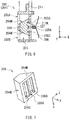
- the three-dimensional shape of the insertion regulating member 204 may be a quadrangular prism shape having top and bottom surfaces that are each a substantially-trapezoidal shape as illustrated in FIG. 7 , for example.
- the fixing member 206 may be inserted into one of the fixing depressions 205B and 205C when the insertion regulating member 204 is located at the regulating position, for example.
- the insertion regulating member 204 located at the regulating position may be thus fixed fully by the fixing member 206.
- the developer container 300 may include the engaging section 301 that is provided in part of the housing 311, for example.
- the engaging section 301 may include a partially-protruding part, i.e., the protrusion 302, for example.
- the protrusion 302 may be disposed in one of two protrusion regions R1 and R2.
- the "two protrusion regions R1 and R2" may each be a position in which the protrusion 302 is disposed. Positions of the two protrusion regions R1 and R2 may correspond to the respective positions of the two openings 202A and 202B provided in the development processor 200.
- the protrusion 302 may correspond to a "protrusion" in one specific but non-limiting embodiment of the technology.
- the protrusion region R1 may correspond to a "first protrusion region” in one specific but non-limiting embodiment of the technology.
- the protrusion region R2 may correspond to a "second protrusion region” in one specific but non-limiting embodiment of the technology.
- the engaging section 301 may have a protrusion depression 303 in a region covering from the protrusion region R1 to the protrusion region R2, for example.
- the engaging section 301 may include a protrusion member 304, for example.
- the protrusion member 304 may be insertable into the protrusion depression 303, for example.
- One reason why the protrusion member 304 is described as being "insertable into the protrusion depression 303" is that the protrusion member 304 may be inserted into the protrusion depression 303 on an as-needed basis, i.e., the protrusion member 304 may be attachable to and detachable from the protrusion depression 303 on an as-needed basis.
- FIG. 8 illustrates a state where the protrusion member 304 is away from the protrusion depression 303 for the sake of easier understanding of a relationship between the protrusion depression 303 and the protrusion member 304.
- the embedded part 305 may be contained in the protrusion depression 303, and the protrusion 302 may protrude from the protrusion depression 303. It is thus possible to fill the protrusion depression 303 with part of the protrusion member 304, i.e., the embedded part 305, and to cause only other part of the protrusion member 304, i.e., only the protrusion 302 to protrude from the protrusion depression 303.
- a three-dimensional shape of the alignment projection 306 is not particularly limited.
- the three-dimensional shape of the alignment projection 306 may be a cylindrical shape, a prism shape, or any other shape, for example.
- Non-limiting examples of the prism shape may include a quadrangular prism shape and a pentagonal prism shape.
- a three-dimensional shape of the alignment opening 304K is not particularly limited and may be any shape that allows the alignment projection 306 to be inserted into the alignment opening 304K.
- the three-dimensional shape of the alignment opening 304K may be the same as the three-dimensional shape of the alignment projection 306 described above, or may be different from the three-dimensional shape of the alignment projection 306 described above.
- the protrusion member 304 may include both the protrusion 302 and the embedded part 305. One reason for this is to prevent the developer container 300 from being unattachable to the development processor 200 unintentionally.
- the following description refers, as an example, to an attachment regulating operation with the engaging section 301 in the first row and the engaged section 201 in the first row.
- the insertion regulating member 204 may be fully fixed by the fixing member 206 as described above. Therefore, a state in which the insertion regulating member 204 is located at the regulating position may be maintained even after the developer container 300 is detached from the development processor 200.
- the charging roller 213 in the development processor 200 may apply a direct-current voltage to the surface of the photosensitive drum 212 while rotating, in response to the rotation of the photosensitive drum 212.
- the surface of the photosensitive drum 212 may be thereby electrically charged in an even manner.
- the developing roller 215 may rotate while being so pressed against the feeding roller 217 as to be in contact with the feeding roller 217, after application of a voltage to the development roller 215. This may cause the developer 314 fed on the surface of the feeding roller 217 to be adsorbed onto the surface of the developing roller 215.
- the developer 314 may be therefore conveyed by utilizing the rotation of the developing roller 215.
- part of the developer 314 adsorbed onto the surface of the developing roller 215 may be removed by the developing blade 218. This may allow the thickness of the developer 314 adsorbed onto the surface of the developing roller 215 to be even.
- the development unit 100 may include the attached unit (the development processor 200) having the engaged section 201 and the attachable unit (the developer container 300) having the engaging section 301.
- the state of the engaged section 201 changes in response to the engagement of the engaging section 301.
- the state of the engaged section 201 upon the engagement of the engaging section 301 i.e., the state of the engaged section 201 after the change is maintained even after the engaging section 301 is detached from the engaged section 201.
- an inappropriate developer container 300 is prevented from being attached to the development processor 200 after the insertion regulating member 204 has moved to the regulating position as described above. It is therefore possible to prevent the developer container 300 from being mistakenly attached to the development processor 200.
- the insertion regulating member 204 is fixed temporarily and fully by the fixing member 206 under the conditions that: the insertion regulating member 204 has the fixing depression 205A having a relatively-smaller depth and the fixing depressions 205B and 205C each having a relatively-greater depth; and the fixing member 206 is insertable into any of the fixing depressions 205A to 205C. It is therefore possible to achieve a higher effect.
- the fixing member 206 that has been inserted into the fixing depression 205A it is easier for the fixing member 206 that has been inserted into the fixing depression 205A to be removed from the fixing depression 205A on an as-needed basis when the inner wall surface, of the insertion regulating member 204, inside the fixing depression 205A is so sloped that the depth of the fixing depression 205A gradually increases in a direction of being closer to the fixing depression 205A from each of the pair of fixing depressions 205B and 205C. It is therefore possible to achieve a higher effect.
- the insertion regulating member 226 may have a function of regulating (permitting or prohibiting) insertion of the protrusion 302 into the insertion chamber 224, which may be called an insertion regulating function.
- the insertion regulating member 225 may be so pressed by the inserted protrusion 302 as to move backward.
- the insertion regulating member 226 may be so pressed by the movement controlling member 228 as to move forward, thereby exhibiting the foregoing insertion control function.
- the insertion regulating member 226 may be thus movable in the insertion direction (the X direction) of the protrusion 302.
- the insertion regulating member 226 may be movable from the initial position to the regulating position.
- which of the insertion regulating members 225 and 226 is pressed by the protrusion 302 may depend on whether the protrusion 302 is inserted into the insertion chamber 223 from the opening 221 or whether the protrusion 302 is inserted into the insertion chamber 224 from the opening 222.
- a three-dimensional shape of the fixing depression 227UB may be a triangular prism shape having an upper surface and a lower surface (a bottom surface) that each has an isosceles triangle shape or any other shape, for example.
- One reason for this is that it is easier for the projection 225P to be removed from the fixing depression 227UB on an as-needed basis upon the movement (the forward movement or the backward movement) of the insertion regulating member 225 located at the initial position. This allows the insertion regulating member 225 to move more easily and more stably.
- each of the foregoing sloped surfaces may include only a flat surface, include only a curved surface, or include both the flat surface and the curved surface.
- the number of the engaged section 220 provided in the development processor 200 may be one, or two or more, as with the number of the engaging section 301 provided in the developer container 300.
- the number of the engaged section 220 and the number of the engaging section 301 may be preferably equal to each other.
- FIG. 14 illustrates an example case where the number of the engaged section 220 is two, and the two engaged sections 220 are disposed in the Z direction.
- An operation of the development unit 100 according to the present example embodiment may be similar to the operation of the development unit 100 according to the first example embodiment except that the development unit 100 according to the present example embodiment may perform the attachment regulating operation by the following procedure.
- the projection 226P may be inserted into the fixing depression 227UD when the insertion regulating member 226 is located at the initial position.
- the height of the projection 226P may gradually increase in the insertion direction of the protrusion 302
- the depth of the fixing depression 227UD gradually increases in the insertion direction of the protrusion 302 and thereafter gradually decreases in the insertion direction of the protrusion 302. It may be therefore easy for the projection 226P to be removed from the fixing depression 227UD.
- the insertion regulating member 226 may be thus fixed temporarily by the projection 226P in accordance with the insertion of the projection 226P into the fixing depression 227UD.
- the engaged section 220 includes the insertion regulating members 225 and 226; and one of the insertion regulating members 225 and 226 is movable from the initial position to the regulating position.
- the movement controlling member 228 having the following configuration is provided.
- each of the insertion regulating members 225 and 226 is suppressed when the separating member 227 has the two fixing depressions 227UA and 227UB into which the projection 225P is to be inserted and also has the two fixing depressions 227UC and 227UD into which the projection 226P is to be inserted. It is therefore possible to achieve a higher effect.
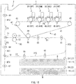
- the image forming apparatus described below may be a full-color printer using an electrophotographic method, for example.
- the image forming apparatus may form an image on a surface of a medium M, for example.
- a material of the medium M is not particularly limited. However, the material of the medium M may be one or more of materials such as paper and a film.
- the one or more trays 10 each may contain the medium M.
- the one or more trays 10 may each be attached to the housing 1 detachably, for example.
- One or more trays 10 may each contain a plurality of media M in a stacked state, for example.
- the media M may be picked out one by one from the corresponding tray 10 by the corresponding feeding roller 20.
- the one or more developing units 30 each may perform a development process with a developer.
- the one or more developing units 30 each may have a configuration similar to that of the development unit according to any one of the foregoing example embodiments of the technology.
- the one or more developing units 30 each may have a configuration similar to that of the development unit 100 according to the foregoing first example embodiment, or may have a configuration similar to that of the development unit 100 according to the foregoing second example embodiment.
- the conveying path switching guides 71 and 72 each may switch the conveying direction of the medium M depending on conditions such as a manner in which an image is formed on the medium M.
- the conditions on the manner in which an image is formed on the medium M may include whether an image is formed on only one surface of the medium M and whether images are formed on both surfaces of the medium M, for example.
- the primary transfer process may involve application of a voltage to the primary transfer roller 45Y.
- the primary transfer roller 45Y may be so pressed against the photosensitive drum as to be in contact with the photosensitive drum with the intermediate transfer belt 41 in between. Accordingly, the yellow developer that has been attached onto the surface of the photosensitive drum, i.e., onto the electrostatic latent image in the foregoing developing process may be transferred onto the intermediate transfer belt 41.
- the intermediate transfer belt 41 onto which the yellow developer is transferred may continue to travel in the direction indicated by the arrow F5.
- the developing process and the primary transfer process may be sequentially performed by the developing units 30M, 30C, and 30K, and the primary transfer rollers 45M, 45C, and 45K.
- the procedure of the developing process and the primary transfer process performed by the developing units 30M, 30C, and 30K, and the primary transfer rollers 45M, 45C, and 45K may be similar to that performed by the developing unit 30Y and the primary transfer roller 45Y described above.
- the developers of the respective colors may be sequentially transferred onto the intermediate transfer belt 41 in such a manner. The developer images of the respective colors may be thus formed on the intermediate transfer belt 41.
- the procedure of conveying the medium M may vary depending on a manner in which an image is formed on the surface of the medium M, which is not described in detail in this description.
- Unnecessary remains of the developer may be present on the surface of the photosensitive drum in the developing unit 30Y.
- the unnecessary remains of the developer may be part of the developer that has been used in the primary transfer process, which may be the developer that has remained on the surface of the photosensitive drum without being transferred onto the intermediate transfer belt 41, for example.
- the foregoing cleaning process using the cleaning blade may be performed similarly in each of the developing units 30M, 30C, and 30K.
Landscapes
- Physics & Mathematics (AREA)
- General Physics & Mathematics (AREA)
- Engineering & Computer Science (AREA)
- Computer Vision & Pattern Recognition (AREA)
- Electrophotography Configuration And Component (AREA)
- Dry Development In Electrophotography (AREA)
Abstract
Description
- The technology relates to: a developer containing unit that contains a developer; a development processing unit that attaches, onto an electrostatic latent image, the developer fed from the developer containing unit; a development unit including the developer containing unit and the development processing unit; and an image forming apparatus that includes the development unit.
- An image forming apparatus using an electrophotographic method is in widespread use. One reason for this is that the image forming apparatus using the electrophotographic method is able to achieve a high-quality image in a shorter time, compared to an image forming apparatus using other method such as an inkjet method.
- An image forming apparatus forms an image on a surface of a medium such as paper. A process of forming an image involves formation of an electrostatic latent image on a surface of a photosensitive drum, which is followed by attachment of a developer onto the formed electrostatic latent image. The developer attached onto the electrostatic latent image is transferred onto the medium. Thereafter, heat and pressure are applied onto the developer transferred onto the medium. The developer is thereby fixed onto the medium.
- The image forming apparatus includes a development unit that attaches the developer onto the electrostatic latent image. The development unit may include a developer containing unit and a development processing unit. The developer containing unit may contain the developer. The development processing unit may attach, onto the electrostatic latent image, the developer fed from the developer containing unit. The developer containing unit may be attachable to and detachable from the development processing unit.
- An image forming apparatus that forms a full-color image uses two or more kinds of developers that are colored in colors different from each other. The image forming apparatus is accordingly provided with two or more kinds of developer containing units.
- When providing two or more kinds of developer containing units, each of the developer containing units may be provided with, for example, a display directed to distinguishing the developer containing units in order to prevent the two or more developer containing units from being attached mistakenly. For example, reference is made to Japanese Unexamined Patent Application Publication No.
2006-099132 - Specific consideration has been made in order to prevent attachment from being performed mistakenly. However, measures against attachment performed mistakenly have not been sufficient yet, and there is still room for improvement in preventing attachment from being performed mistakenly.
- It is desirable to provide a developer containing unit, a development processing unit, a development unit, and an image forming apparatus that are each able to prevent attachment from being performed mistakenly.
- According to one embodiment of the technology, there is provided a development unit that includes an attachable unit and an attached unit. The attachable unit includes an engaging section. The attached unit includes an engaged section that allows the engaging section to be brought into engagement with the engaged section attachably and detachably, and whose state changes in response to the engagement of the engaging section. The state of the engaged section upon the engagement of the engaging section is maintained even after the engaging section is detached from the engaged section.
- According to one embodiment of the technology, there is provided a development processing unit that includes an engaged section that allows an engaging section of an attachable unit to be brought into engagement with the engaged section attachably and detachably, and whose state changes in response to the engagement of the engaging section. The state of the engaged section upon the engagement of the engaging section is maintained even after the engaging section is detached from the engaged section.
- According to one embodiment of the technology, there is provided a developer containing unit that includes an engaging section that is to be brought into engagement with an engaged section of an attached unit attachably and detachably. The engaging section includes a protrusion that is provided in one of a first protrusion region and a second protrusion region.
- According to one embodiment of the technology, there is provided an image forming apparatus that includes the foregoing development unit.
-
-
FIG. 1 is a perspective view of a configuration example of a development unit according to first example embodiment of the technology. -
FIG. 2 is a perspective view of a configuration example of a development processor. -
FIG. 3 is an enlarged perspective view of a part A of the configuration of the development processor illustrated inFIG. 2 . -
FIG. 4 is a perspective view of a configuration example of a developer container. -
FIG. 5 is a plan view of an example of each of the configurations of the development processor and the developer container. -
FIG. 6 is a cross-sectional view of a configuration example of a key part of the development processor. -
FIG. 7 is a perspective view of a configuration example of an insertion regulating member. -
FIG. 8 is a cross-sectional view of a configuration example of a key part of the developer container. -
FIG. 9 is a perspective view of a configuration example of the key part of the developer container. -
FIG. 10 is a cross-sectional diagram describing an example procedure of attachment of the developer container to the development processor. -
FIG. 11 is a cross-sectional diagram describing an example procedure of the attachment following the procedure illustrated inFIG. 10 . -
FIG. 12 is a cross-sectional diagram describing an example procedure of the attachment following the procedure illustrated inFIG. 11 . -
FIG. 13 is a cross-sectional diagram describing an example procedure of the attachment following the procedure illustrated inFIG. 12 . -
FIG. 14 is a cross-sectional view of a configuration example of a key part of a development unit according to a second example embodiment of the technology. -
FIG. 15 is a cross-sectional diagram describing an example procedure of attachment of the developer container to the development processor. -
FIG. 16 is a cross-sectional diagram describing an example procedure of the attachment following the procedure illustrated inFIG. 15 . -
FIG. 17 is a cross-sectional diagram describing an example procedure of the attachment following the procedure illustrated inFIG. 16 . -
FIG. 18 schematically illustrates a configuration example of an image forming apparatus according to one example embodiment of the technology. -
FIG. 19 is a cross-sectional diagram describing a modification of the configuration of the development unit. - Some example embodiments of the technology are described below in detail with reference to the drawings. The description is given in the following order.
- 1. Development Unit: First Example Embodiment
- 1-1. Overall Configuration
- 1-2. Detailed Configuration of Development Processor (Development Processing Unit)
- 1-3. Detailed Configuration of Developer Container (Developer Containing Unit)
- 1-4. Attachment Mechanism
- 1-5. Operation
- 1-6. Workings and Effects
- 2. Development Unit: Second Example Embodiment
- 2-1. Configuration
- 2-2. Operation
- 2-3. Workings and Effects
- 3. Image Forming Apparatus
- 3-1. Overall Configuration
- 3-2. Operation
- 3-3. Workings and Effects
- 4. Modifications
- A development unit according to a first example embodiment of the technology is described below.
- The development unit described below may be used in an image forming apparatus that forms an image by means of attachment of a developer onto an electrostatic latent image, for example.
- It is to be noted that a developer containing unit according to the first example embodiment of the technology and a development processing unit according to the first example embodiment of the technology may be applied to the development unit described below, for example. The developer containing unit and the development processing unit according to the first example embodiment are therefore described together with the development unit according to the first example embodiment below.
- An overall configuration of the development unit according to the present example embodiment is described below.
-
FIGs. 1 to 4 each illustrate a configuration of adevelopment unit 100. Thedevelopment unit 100 may correspond to a "development unit" in one specific but non-limiting embodiment of the technology. Specifically,FIG. 1 is a perspective view of the configuration of thedevelopment unit 100.FIG. 2 is a perspective view of a configuration of adevelopment processor 200.FIG. 3 enlarges a part A of the perspective view of the configuration of thedevelopment processor 200 illustrated inFIG. 2 .FIG. 4 is a perspective view of a configuration of adeveloper container 300. - The
development unit 100 may include thedevelopment processor 200 and thedeveloper container 300 as illustrated inFIGs. 1 to 4 , for example. Thedeveloper container 300 is attachable to thedevelopment processor 200 in a detachable manner.FIG. 2 illustrates a state in which thedeveloper container 300 is detached from thedevelopment processor 200. - The
development processor 200 may correspond to the development processing unit according to the first example embodiment of the technology. Thedevelopment processor 200 may correspond to an "attached unit" in one specific but non-limiting embodiment of the technology. Thedevelopment processor 200 may attach, onto an electrostatic latent image, adeveloper 314 illustrated inFIG. 5 that is fed from thedeveloper container 300 which will be described later. - In particular, referring to
FIGs. 2 and3 , thedevelopment processor 200 may include an engagedsection 201, for example. The engagedsection 201 may be used upon attachment of thedeveloper container 300 to thedevelopment processor 200. A detailed configuration of thedevelopment processor 200 will be described later. - The
developer container 300 may correspond to the developer containing unit according to the first example embodiment of the technology. Thedeveloper container 300 may be a so-called toner cartridge, for example. Thedeveloper container 300 may correspond to an "attachable unit" in one specific but non-limiting embodiment of the technology. Thedeveloper container 300 may contain the foregoingdeveloper 314. - In particular, referring to
FIG. 4 , thedeveloper container 300 may include an engagingsection 301, for example. The engagingsection 301 may be directed to the attachment of thedeveloper container 300 to thedevelopment processor 200.FIG. 4 illustrates only part of thedeveloper container 300, i.e., the engagingsection 301 and a part around the engagingsection 301. A detailed configuration of thedeveloper container 300 will be described later. - The
development unit 100 may have an attachment mechanism that attaches thedeveloper container 300 to thedevelopment processor 200 by means of the engagedsection 201 and the engagingsection 301 as described above. The engagedsection 201 and the engagingsection 301 may also have a function of aligning thedevelopment processor 200 and thedeveloper container 300 to each other upon the attachment of thedeveloper container 300 to thedevelopment processor 200. The attachment mechanism will be described later in detail. - The detailed configuration of the
development processor 200 is described below. -
FIG. 5 illustrates a plan configuration in an YZ plane of each of thedevelopment processor 200 and thedeveloper container 300.FIG. 5 illustrates a state in which thedeveloper container 300 is attached to thedevelopment processor 200.FIG. 5 omits illustration of the engagedsection 201. - Referring to
FIG. 5 , thedevelopment processor 200 may include ahousing 211. Thedevelopment processor 200 may include, inside thehousing 211, aphotosensitive drum 212, a chargingroller 213, a light emitting diode (LED)head 214, a developingroller 215, acleaning blade 216, a feedingroller 217, and a developingblade 218, for example. - The
photosensitive drum 212 may be an organic photoreceptor that includes a cylindrical electrically-conductive supporting body and a photoconductive layer, for example. The photoconductive layer may cover an outer peripheral surface of the electrically-conductive supporting body. Thephotosensitive drum 212 may be rotatable with a drive source such as a motor. The electrically-conductive supporting body may be a metal pipe that includes a metal material such as aluminum, for example. The photoconductive layer may be a stack that includes layers including an electric charge generating layer and an electric charge transfer layer, for example. Thehousing 211 may have anopening 219 from which thephotosensitive drum 212 is to be partially exposed, for example. - The charging
roller 213 may include a metal shaft and an electrically-semiconductive epichlorohydrin rubber layer that covers an outer peripheral surface of the metal shaft, for example. The chargingroller 213 may be rotatable with a drive source such as a motor. The chargingroller 213 may be so pressed against thephotosensitive drum 212 as to be in contact with thephotosensitive drum 212, thereby charging the surface of thephotosensitive drum 212. - The
LED head 214 may be an exposure device that performs exposure of the surface of thephotosensitive drum 212, and thereby forms an electrostatic latent image on the surface of thephotosensitive drum 212. TheLED head 214 may include an LED device and a lens array, for example. The LED device and the lens array may be so disposed that light (irradiation light) outputted from the LED device is imaged on the surface of thephotosensitive drum 212. Thehousing 211 may have anopening 220 that guides the light outputted from theLED head 214 to thephotosensitive drum 212, for example. - The developing
roller 215 may include a metal shaft and an electrically-semiconductive urethane rubber layer that covers an outer peripheral surface of the metal shaft, for example. The developingroller 215 may be rotatable with a drive source such as a motor. The developingroller 215 may support thedeveloper 314 that is fed from the feedingroller 217, and attach thefed developer 314 onto the electrostatic latent image formed on the surface of thephotosensitive drum 212. - The
cleaning blade 216 may scrape off unnecessary remains of thedeveloper 314 that are present on the surface of thephotosensitive drum 212. Thecleaning blade 216 may extend in a direction intersecting a paper plane ofFIG. 5 , i.e., a direction substantially parallel to a rotation axis of thephotosensitive drum 212, for example. Thecleaning blade 216 may be so pressed against thephotosensitive drum 212 as to be in contact with thephotosensitive drum 212. Thecleaning blade 216 may include a polymer material such as urethane rubber, for example. - The feeding
roller 217 may include a metal shaft and an electrically-semiconductive foamed silicone sponge layer that covers an outer peripheral surface of the metal shaft, for example. The feedingroller 217 may be rotatable with a drive source such as a motor. The feedingroller 217 may feed thedeveloper 314 to the surface of the developingroller 215 while being in contact with the developingroller 215 in a slidable manner. - The developing
blade 218 may control the thickness of thedeveloper 314 fed on the surface of the developingroller 215. The developingblade 218 may be so disposed as to be away from the developingroller 215 with a predetermined spacing in between. The thickness of thedeveloper 314 may be controlled on the basis of the predetermined spacing. The developingblade 218 may include a metal material such as stainless steel, for example. - A detailed configuration of the
developer container 300 is described below with reference toFIG. 5. FIG. 5 omits illustration of the engagingsection 301. - Referring to
FIG. 5 , thedeveloper container 300 may include ahousing 311. Thedeveloper container 300 may include a stirringbar 313 inside thehousing 311, for example. Specifically, thedeveloper container 300 may include the stirringbar 313 in a containingchamber 312, for example. - The containing
chamber 312 may contain thedeveloper 314. The containingchamber 312 may have anoutlet 315 from which thedeveloper 314 is to be discharged to thedevelopment processor 200. Theoutlet 315 may be provided with ashutter 316 that is to be opened and closed utilizing a slide mechanism, for example.FIG. 5 illustrates an example case where theshutter 316 is open. - The stirring
bar 313 may extend in a direction intersecting the paper plane ofFIG. 5 , for example. The stirringbar 313 may be rotatable around a rotation axis that extends in the direction in which the stirringbar 313 extends. The stirringbar 313 may stir thedeveloper 314 contained in the containingchamber 312. - The
developer 314 may be so-called toner, for example. A configuration of thedeveloper 314 such as a color of thedeveloper 314 is not particularly limited. - An attachment mechanism of the
development unit 100 is described below. - The
development unit 100 may allow for attachment of thedeveloper container 300 to thedevelopment processor 200 by utilizing the engagedsection 201 provided in thedevelopment processor 200 and the engagingsection 301 provided in thedeveloper container 300, as described above. - In particular, the
development unit 100 may have a function of preventing attachment of thedeveloper container 300 to thedevelopment processor 200 from being performed mistakenly. Specifically, upon the attachment of thedeveloper container 300 to thedevelopment processor 200, when the engagingsection 301 is brought into engagement with the engagedsection 201 attachably and detachably, the state of the engagedsection 201 changes in response to the engagement of the engagingsection 301. The state, after the foregoing change, of the engagedsection 201 upon the engagement of the engagingsection 301 is maintained even after the engagingsection 301 is detached from the engagedsection 201. Some reasons that prevent attachment from being performed mistakenly will be described later in detail. -
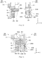
FIG. 6 illustrates a cross-sectional configuration, in an XZ plane, of a key part of thedevelopment processor 200.FIG. 7 is a perspective view of a configuration of aninsertion regulating member 204.FIG. 8 illustrates a cross-sectional configuration in the XZ plane of a key part of thedeveloper container 300.FIG. 9 is a perspective view of a configuration of a key part of thedeveloper container 300.FIG. 6 illustrates a cross-section of thedevelopment processor 200 taken along a line VI-VI ofFIG. 3 . - Referring to
FIG. 6 , thedevelopment processor 200 may have the engagedsection 201 that is provided in part of thehousing 211, for example. The engagedsection 201 may include theinsertion regulating member 204 and a fixingmember 206, for example. Theinsertion regulating member 204 may be disposed inside aninsertion chamber 203, for example. The fixingmember 206 may be disposed outside theinsertion chamber 203, for example.FIG. 6 illustrates a state in which the fixingmember 206 is away from theinsertion regulating member 204 for the sake of easier understanding of the configuration of theinsertion regulating member 204. - The
insertion chamber 203 may have space into which part of thedeveloper container 300 is inserted upon the attachment of thedeveloper container 300 to thedevelopment processor 200. Specifically, the part of thedeveloper container 300 to be inserted into theinsertion chamber 203 may be aprotrusion 302 illustrated inFIG. 8 which will be described later. Theinsertion chamber 203 may have twoopenings protrusion 302 is insertable. Theopening 202A may correspond to a "first opening" in one specific but non-limiting embodiment of the technology. Theopening 202B may correspond to a "second opening" in one specific but non-limiting embodiment of the technology. Theprotrusion 302 may be insertable into theinsertion chamber 203 from theopening 202A. Theprotrusion 302 may be also insertable into theinsertion chamber 203 from theopening 202B. In other words, theprotrusion 302 may be insertable into theinsertion chamber 203 from either of theopenings - The
insertion regulating member 204 may have a function of regulating (permitting or prohibiting) insertion of theprotrusion 302 into theinsertion chamber 203, which may be called an insertion regulating function. Accordingly, theinsertion regulating member 204 may be movable from an initial position to a regulating position in a direction (a Z direction) intersecting an insertion direction (an X direction) of theprotrusion 302. Such a movement of theinsertion regulating member 204 may be performed in response to the insertion of theprotrusion 302 into theinsertion chamber 203. The "insertion direction of theprotrusion 302" is a direction in which theprotrusion 302 is inserted, and is also referred to as a protruding direction or an extending direction of theprotrusion 302 in other words. - When the
insertion regulating member 204 is located at the "initial position", theinsertion regulating member 204 may allow theprotrusion 302 to be inserted into theinsertion chamber 203 from theopening 202A, as illustrated inFIG. 10 which will be described later. In other words, when theinsertion regulating member 204 is located at the initial position, theinsertion regulating member 204 may not prevent theprotrusion 302 from being inserted into theinsertion chamber 203 from theopening 202A, i.e., to permit theprotrusion 302 to be inserted into theinsertion chamber 203 from theopening 202A. - It is to be noted that the
protrusion 302 may be insertable into theinsertion chamber 203 from either of theopenings insertion regulating member 204 is located at the initial position, theinsertion regulating member 204 may alternatively allow theprotrusion 302 to be inserted into theinsertion chamber 203 from theopening 202B. - In contrast, when the
insertion regulating member 204 is located at the "regulating position", theinsertion regulating member 204 may prevent theprotrusion 302 from being inserted into theinsertion chamber 203 from theopening 202B, in response to the insertion of theprotrusion 302 into theinsertion chamber 203 from theopening 202A as illustrated inFIGs. 11 to 13 which will be described later. In other words, when theinsertion regulating member 204 is located at the regulating position, theinsertion regulating member 204 may prevent theprotrusion 302 from being inserted into theinsertion chamber 203 from theopening 202B after theprotrusion 302 is inserted into theinsertion chamber 203 from theopening 202A, i.e., theinsertion regulating member 204 may prohibit the insertion of theprotrusion 302 into theinsertion chamber 203 from theopening 202B. - It is to be noted that the
protrusion 302 may be insertable into theinsertion chamber 203 from either of theopenings insertion regulating member 204 is located at the regulating position, theinsertion regulating member 204 may alternatively prevent theprotrusion 302 from being inserted into theinsertion chamber 203 from theopening 202A in response to the insertion of theprotrusion 302 into theinsertion chamber 203 from theopening 202A. - More specifically, the
insertion regulating member 204 may have a particular shape in order to exhibit the insertion regulating function described above, for example. Specifically, theinsertion regulating member 204 may include a pair of slopedsurfaces 204M at positions corresponding to therespective openings insertion regulating member 204 is located at the initial position. The pair of slopedsurfaces 204M may be able to be brought into contact with theprotrusion 302 and be sloped with respect to the insertion direction of theprotrusion 302. - One reason why the
insertion regulating member 204 includes the pair of slopedsurfaces 204M is that the pair of slopedsurfaces 204M makes it easier for theinsertion regulating member 204 to move from the initial position to the regulating position by utilizing an insertion operation of theprotrusion 302 upon the insertion of theprotrusion 302 into theinsertion chamber 203. Specifically, upon the insertion of theprotrusion 302 into theinsertion chamber 203, theprotrusion 302 may be guided deeply into theinsertion chamber 203 while being in contact with one of the slopedsurfaces 204M. At this time, theinsertion regulating member 204 may be pressed by theprotrusion 302 in the direction (the Z direction) intersecting the insertion direction of theprotrusion 302, and be thereby moved from the initial position to the regulating position. - As can be appreciated from
FIG. 6 , a direction in which theinsertion regulating member 204 is pressed by theprotrusion 302 depends on from which of theopenings protrusion 302 is inserted into theinsertion chamber 203. - Specifically, the
insertion regulating member 204 may be pressed in the Z direction by theprotrusion 302 when theprotrusion 302 is inserted into theinsertion chamber 203 from theopening 202A, for example. The Z direction may correspond to a downward direction inFIG. 6 , for example. Theinsertion regulating member 204 may be therefore moved from the initial position to the regulating position in the downward direction. - In contrast, the
insertion regulating member 204 may be pressed in the Z direction by theprotrusion 302 when theprotrusion 302 is inserted into theinsertion chamber 203 from theopening 202B, for example. The Z direction may correspond to an upward direction inFIG. 6 , for example. Theinsertion regulating member 204 may be therefore moved from the initial position to the regulating position in the upward direction. - It is to be noted that a state of the pair of sloped
surfaces 204M is not particularly limited as long as the state of the pair of slopedsurfaces 204M allows theinsertion regulating member 204 to move from the initial position to the regulating position by utilizing the contact of theprotrusion 302 and the insertion regulating member 204 (one of the pair of slopedsurfaces 204M) with each other. - Specifically, each of the pair of sloped
surfaces 204M may be a flat surface, a convex curved surface, a concave curved surface, a convex bent surface, a concave bent surface, or a surface including two or more of the foregoing surfaces, for example. It is to be noted that one of the slopedsurfaces 204M and the other of the slopedsurfaces 204M may have the same state or may have states different from each other. - It may be preferable that each of the pair of sloped
surfaces 204M be a flat surface in particular. One reason for this is that it is easier for theinsertion regulating member 204 to move smoothly and stably by utilizing the contact of theprotrusion 302 and the insertion regulating member 204 (one of the pair of slopedsurfaces 204M) with each other. - For the foregoing reason, a cross-sectional shape of the
insertion regulating member 204 is not particularly limited; however, it may be preferable that the cross-sectional shape of theinsertion regulating member 204 be a substantially-trapezoidal shape having a shorter side onopenings FIG. 6 , for example. In this case, a width of theinsertion regulating member 204, i.e., a dimension of theinsertion regulating member 204 in the Z direction may gradually increase in a direction of being away from theopenings - A three-dimensional shape of the
insertion regulating member 204 is not particularly limited and may be any three-dimensional shape that includes the foregoing pair of slopedsurfaces 204M. In this example, the three-dimensional shape of theinsertion regulating member 204 may be a quadrangular prism shape having top and bottom surfaces that are each a substantially-trapezoidal shape as illustrated inFIG. 7 , for example. - Further, the
insertion regulating member 204 may have three fixingdepressions FIG. 6 ) to side (left side inFIG. 6 ) on which theprotrusion 302 is to be inserted into theinsertion chamber 203, for example. The fixingdepressions insertion regulating member 204. The moving direction of theinsertion regulating member 204 is a direction in which theinsertion regulating member 204 moves. - When the
insertion regulating member 204 is located at the initial position, the fixingdepression 205A may be used to fix theinsertion regulating member 204 with the fixingmember 206. The fixingdepression 205A may correspond to a "first fixing depression" in one specific but non-limiting embodiment of the technology. The wording "fix" used in relation to the foregoing function of the fixingdepression 205A may refer to temporarily fixing the position of theinsertion regulating member 204, while suppressing unintentional variation in the position of theinsertion regulating member 204 due to a cause such as impact and vibration. The temporal fixation of the position of theinsertion regulating member 204 may allow theinsertion regulating member 204 to be movable on an as-needed basis. This can be appreciated from the fact that theinsertion regulating member 204 is movable from the initial position to the regulating position. - The fixing
depression 205A may have a depth, i.e., a dimension in the X direction, that is smaller than a depth of each of the fixingdepressions insertion regulating member 204 located at the initial position to be movable on an as-needed basis. - A shape of the fixing
depression 205A is not particularly limited. The wording the "shape of the fixingdepression 205A" may refer to a three-dimensional shape of space that configures the fixingdepression 205A. For example, the three-dimensional shape of the fixingdepression 205A may be preferably a triangular prism shape in particular, as illustrated inFIG. 6 . Specifically, it may be preferable that the depth of the fixingdepression 205A gradually increase in a direction of being closer to the fixingdepression 205A from the fixingdepression 205B, and gradually increase in a direction of being closer to the fixingdepression 205A from the fixingdepression 205C. In other words, it may be preferable that an inner wall surface of theinsertion regulating member 204, inside the fixingdepression 205A be so sloped that the depth of the fixingdepression 205A gradually increases in the direction of being closer to the fixingdepression 205A from the fixingdepression 205B. Further, it may be preferable that the inner wall surface, of theinsertion regulating member 204, inside the fixingdepression 205A be so sloped that the depth of the fixingdepression 205A gradually increases in a direction of being closer to the fixingdepression 205A from the fixingdepression 205C. In this case, the inner wall surface may include two flat sloped surfaces, for example. One reason for this is that, upon being located in the initial state, it may be easier for theinsertion regulating member 204 to slide in the moving direction of theinsertion regulating member 204 by utilizing the slope of the foregoing inner wall surface, even when the fixingmember 206 is inserted into the fixingdepression 205A. This allows theinsertion regulating member 204 to move easily and stably on an as-needed basis. - However, the foregoing inner wall surface of the
insertion regulating member 204 may include a curved surface, or may include both the flat surface and the curved surface. Specifically, the three-dimensional shape of the fixingdepression 205A may be a semi-cylindrical shape, a semi-spherical shape, or any other shape, for example. - The fixing
depressions depression 205A in the moving direction of theinsertion regulating member 204. When theinsertion regulating member 204 is located at the regulating position, each of the fixingdepressions insertion regulating member 204 with the fixingmember 206. The fixingdepressions depressions insertion regulating member 204, thereby substantially causing theinsertion regulating member 204 to be difficult to move. This may be directed to preventing theinsertion regulating member 204 from moving again after theinsertion regulating member 204 moves from the initial position to the regulating position. - In order to substantially cause the
insertion regulating member 204 that has moved to the regulating position to be difficult to move, each of the fixingdepressions depression 205A, for example. One reason for this is that an amount or a length by which the fixingmember 206 is inserted into any one of the fixingdepressions member 206 to fix theinsertion regulating member 204. - A three-dimensional shape of each of the fixing
depressions FIG. 6 illustrates an example case where the three-dimensional shape of each of the fixingdepressions FIG. 6 illustrates an example case where the three-dimensional shape of each of the fixingdepressions depressions depressions - The fixing
depressions 205A to 205C each may be provided in part of one surface of theinsertion regulating member 204 on the opposite side to the side on which theprotrusion 302 is to be inserted into theinsertion chamber 203, for example, as illustrated inFIG. 7 . The foregoing part of the surface of theinsertion regulating member 204 may be a substantially-middle region of the foregoing surface of theinsertion regulating member 204, for example. - The fixing
member 206 may fix theinsertion regulating member 204 as described above. Specifically, the fixingmember 206 may temporarily fix theinsertion regulating member 204 and fully fix theinsertion regulating member 204. The fixingmember 206 may be so fixed by anauxiliary fixing member 207 that the fixingmember 206 is prevented from moving unintentionally in the moving direction of theinsertion regulating member 204, for example. However, theauxiliary fixing member 207 may not be provided. - The fixing
member 206 may be partially introduced inside theinsertion chamber 203 from anopening 211K that is provided in theinsertion chamber 203, for example. Further, the fixingmember 206 may include a protruding part that protrudes toward theinsertion regulating member 204, for example. The protruding part may be insertable into one of the three fixingdepressions 205A to 205C provided in theinsertion regulating member 204, for example. - Specifically, the fixing
member 206 may be inserted into the fixingdepression 205A when theinsertion regulating member 204 is located at the initial position, for example. Theinsertion regulating member 204 located at the initial position may be thus fixed temporarily by the fixingmember 206. - In contrast, the fixing
member 206 may be inserted into one of the fixingdepressions insertion regulating member 204 is located at the regulating position, for example. Theinsertion regulating member 204 located at the regulating position may be thus fixed fully by the fixingmember 206. - The fixing
member 206 may include an elastic material that is elastically transformable, i.e., expandable and contractible, toward theinsertion regulating member 204, for example. More specifically, the fixingmember 206 may be a spring member such as a plate spring and a coil spring, for example. Accordingly, the fixingmember 206 may also have a function as a biasing member that press the fixingmember 206 against theinsertion regulating member 204, in addition to a function of fixing theinsertion regulating member 204, for example.FIG. 6 illustrates an example case where the fixingmember 206 is the plate spring. - One reason why the fixing
member 206 also has the function as the biasing member that presses the fixingmember 206 against theinsertion regulating member 204 is that making use of the biasing function allows the fixingmember 206 to be easier to be inserted deeply into any one of the fixingdepressions 205A to 205C. This makes it more difficult for the fixingmember 206 after being inserted into any one of the fixingdepressions 205A to 205C to be detached from the corresponding one of the fixingdepressions 205A to 205C. This makes it easier for the fixingmember 206 to fix the position of theinsertion regulating member 204 in both the temporal fixation and the fully-performed fixation of theinsertion regulating member 204. - Referring to
FIGs. 8 and 9 , thedeveloper container 300 may include the engagingsection 301 that is provided in part of thehousing 311, for example. The engagingsection 301 may include a partially-protruding part, i.e., theprotrusion 302, for example. Theprotrusion 302 may be disposed in one of two protrusion regions R1 and R2. The "two protrusion regions R1 and R2" may each be a position in which theprotrusion 302 is disposed. Positions of the two protrusion regions R1 and R2 may correspond to the respective positions of the twoopenings development processor 200. Theprotrusion 302 may correspond to a "protrusion" in one specific but non-limiting embodiment of the technology. The protrusion region R1 may correspond to a "first protrusion region" in one specific but non-limiting embodiment of the technology. The protrusion region R2 may correspond to a "second protrusion region" in one specific but non-limiting embodiment of the technology. - More specifically, the engaging
section 301 may have aprotrusion depression 303 in a region covering from the protrusion region R1 to the protrusion region R2, for example. The engagingsection 301 may include aprotrusion member 304, for example. Theprotrusion member 304 may be insertable into theprotrusion depression 303, for example. One reason why theprotrusion member 304 is described as being "insertable into theprotrusion depression 303" is that theprotrusion member 304 may be inserted into theprotrusion depression 303 on an as-needed basis, i.e., theprotrusion member 304 may be attachable to and detachable from theprotrusion depression 303 on an as-needed basis.FIG. 8 illustrates a state where theprotrusion member 304 is away from theprotrusion depression 303 for the sake of easier understanding of a relationship between theprotrusion depression 303 and theprotrusion member 304. - The
protrusion member 304 may be so inserted into theprotrusion depression 303 that theprotrusion member 304 partially protrudes in one of the two protrusion regions R1 and R2 and does not protrude in other regions, for example. Specifically, theprotrusion member 304 may include a partially-protruding part, i.e., theprotrusion 302 and a part to be embedded in theprotrusion depression 303, i.e., an embeddedpart 305, for example. Theprotrusion 302 and the embeddedpart 305 may be coupled to each other, for example. Accordingly, a cross-sectional shape in an XZ plane of theprotrusion member 304 may be a shape of the letter "L", for example. - When the
protrusion member 304 is inserted into theprotrusion depression 303, the embeddedpart 305 may be contained in theprotrusion depression 303, and theprotrusion 302 may protrude from theprotrusion depression 303. It is thus possible to fill theprotrusion depression 303 with part of theprotrusion member 304, i.e., the embeddedpart 305, and to cause only other part of theprotrusion member 304, i.e., only theprotrusion 302 to protrude from theprotrusion depression 303. - The engaging
section 301 may include analignment projection 306 inside theprotrusion depression 303, for example. Theprotrusion member 304 may have analignment opening 304K into which thealignment projection 306 is insertable, for example. One reason for this is that, when theprotrusion member 304 is inserted into theprotrusion depression 303, theprotrusion member 304 may be aligned with respect to theprotrusion depression 303 by utilizing thealignment projection 306, and theprotrusion member 304 may be fixed while being inserted into theprotrusion depression 303 by utilizing thealignment projection 306. - A three-dimensional shape of the
alignment projection 306 is not particularly limited. However, the three-dimensional shape of thealignment projection 306 may be a cylindrical shape, a prism shape, or any other shape, for example. Non-limiting examples of the prism shape may include a quadrangular prism shape and a pentagonal prism shape. A three-dimensional shape of thealignment opening 304K is not particularly limited and may be any shape that allows thealignment projection 306 to be inserted into thealignment opening 304K. Specifically, the three-dimensional shape of thealignment opening 304K may be the same as the three-dimensional shape of thealignment projection 306 described above, or may be different from the three-dimensional shape of thealignment projection 306 described above. - However, in particular, the three-dimensional shape of the
alignment opening 304K may be preferably a three-dimensional shape that allows the position at which theprotrusion 302 is located to be switched optionally by means of thesingle protrusion member 304. In other words, the three-dimensional shape of thealignment opening 304K may be preferably a three-dimensional shape that allows the position at which theprotrusion 302 is located to be freely switched between the protrusion region R1 and the protrusion region R2 by means of thesingle protrusion member 304. Specifically, the three-dimensional shape of thealignment opening 304K may be preferably a three-dimensional shape that allows for the following. That is, when theprotrusion member 304 is so oriented that theprotrusion 302 is disposed in the protrusion region R1, the thus-orientedprotrusion member 304 is insertable into theprotrusion depression 303, and when theprotrusion member 304 is so oriented that theprotrusion 302 is disposed in the protrusion region R2, the thus-orientedprotrusion member 304 is also insertable into theprotrusion depression 303. - In the foregoing example case, the position of the
protrusion 302 may be variable by varying a state in which theprotrusion member 304 is inserted into theprotrusion depression 303. Specifically, when theprotrusion member 304 is so inserted into theprotrusion depression 303 that theprotrusion 302 is located in the protrusion region R1, part of theprotrusion member 304, i.e., theprotrusion 302 may be allowed to protrude in the protrusion region R1, for example. In contrast, when the orientation of theprotrusion member 304 is varied from that in the foregoing case, and theprotrusion member 304 is thus so inserted into theprotrusion depression 303 that theprotrusion 302 is located in the protrusion region R2, part of theprotrusion member 304, i.e., theprotrusion 302 may be allowed to protrude in the protrusion region R2, for example. It is thus possible to freely set the position at which theprotrusion member 304 partially protrudes by means of thesingle protrusion member 304. - It is to be noted that the
protrusion member 304 may have an alignment depression instead of thealignment opening 304K, for example. Also in this example case where theprotrusion member 304 has the alignment depression, theprotrusion member 304 may be aligned and fixed due to insertion of thealignment projection 306 into the alignment depression. - The
protrusion member 304 may include both theprotrusion 302 and the embeddedpart 305. One reason for this is to prevent thedeveloper container 300 from being unattachable to thedevelopment processor 200 unintentionally. - More in detail, in order to achieve the partial protrusion of part of the
protrusion member 304, i.e., theprotrusion 302, another protrusion member may be usable instead of theprotrusion member 304, for example. Specifically, instead of theprotrusion member 304 having the cross-sectional shape of the letter "L", a protrusion member having a rectangular cross-sectional shape that extends in the extending direction of theprotrusion 302 may be used, for example. When such a protrusion member is used, part, of theprotrusion depression 303, corresponding to the protrusion region R1 is filled with this protrusion member; however, other part of theprotrusion depression 303 is not filled with this protrusion member. - The
development processor 200 may have the configuration described above in which, after theprotrusion 302 is inserted into theinsertion chamber 203 from theopening 202A, the insertion of theprotrusion 302 into theinsertion chamber 203 from theopening 202B is prohibited by utilizing the insertion regulating function of theinsertion regulating member 204, for example. Consideration is given below to an example case in which thedeveloper container 300 is attached to thedevelopment processor 200 while the foregoing protrusion member having the rectangular cross-sectional shape is so inserted into theprotrusion depression 303 that theprotrusion 302 is located in the protrusion region R1, and thedeveloper container 300 is thereafter detached from thedevelopment processor 200. In this case, another protrusion member may be so mistakenly inserted into theprotrusion depression 303 that protrusion 302 is also located in the protrusion region R2, in addition to that the foregoing protrusion member is so inserted into theprotrusion depression 303 that theprotrusion 302 is located in the protrusion region R1. In such a state, when an attempt is made to attach thedeveloper container 300 to thedevelopment processor 200, thedeveloper container 300 is unattachable to thedevelopment processor 200. One reason for this is that theprotrusion 302 located in the protrusion region R2 is not insertable into theinsertion chamber 203 from theopening 202B. - In contrast, in the example case where the
protrusion member 304 is used, theprotrusion 302 may protrude in the protrusion region R1 and the embeddedpart 305 may fill theprotrusion depression 303. This may prevent theprotrusion 302 from being disposed in the protrusion region R2 mistakenly. As a result, thedeveloper container 300 may be prevented from becoming unattachable to thedevelopment processor 200 due to theprotrusion 302 mistakenly disposed in the protrusion region R2. -
FIGs. 8 and 9 each illustrate an example case where theprotrusion member 304 is so inserted into theprotrusion depression 303 that theprotrusion 302 is disposed in the protrusion region R1. - It is to be noted that the number of the engaged
section 201 provided in thedevelopment processor 200 may be one, or two or more. In other words, when components including theinsertion chamber 203 and theinsertion regulating member 204 of the engagedsection 201 is considered as a set, the number of set of the components including theinsertion chamber 203 and theinsertion regulating member 204 may be one, or two or more. - Similarly, the number of the engaging
section 301 provided in thedeveloper container 300 may be one, or two or more. In other words, when components including theprotrusion depression 303 and theprotrusion 302 of the engagingsection 301 are considered as a set, the number of set of the components including theprotrusion depression 303 and theprotrusion 302 may be one, or two or more. - When the number of the engaged
section 201 is two or more, a positional relationship between the two or moreengaged sections 201 is not particularly limited. However, the two or moreengaged sections 201 may be preferably arranged at any intervals on an as-needed basis, in particular. One reason for this is that a region occupied by the engagedsections 201 is thereby reduced, allowing for a reduction in volume of the engagedsections 201. - The positional relationship between the two or more
engaged sections 201 is not particularly limited as described above. This is also applicable to the two or moreengaging sections 301. - It is to be noted that the number of the engaged
section 201 and the number of the engagingsection 301 may be preferably equal to each other. One reason for this is that, a difference in number between the engagedsection 201 and the engagingsection 301 results in presence of theprotrusion 302 that is not able to be inserted into theinsertion chamber 203, making it more difficult to attach thedeveloper container 300 to thedevelopment processor 200. -
FIGs. 2 and3 each illustrates an example case where the number of the engagedsections 201 is two, and the two engagedsections 201 are arranged in the Z direction. Further,FIG. 4 illustrates an example case where the number of the engagingsection 301 is two and the twoengaging sections 301 are arranged in the Z direction, which correspond to the number and the arrangement state of the engagedsections 201 described above. - The
development processor 200 may be provided with the two engagedsections 201 that are arranged in the Z direction as described above, for example. In this example case, thedevelopment processor 200 may be provided with the engagedsection 201 in a first row and the engagedsection 201 in a second row. The first row may be the upper row, and the second row may be the lower row. Each of the engagedsections 201 in the first and second rows may have theopenings insertion chamber 203, for example. - The
developer container 300 may be provided with the twoengaging sections 301 that are arranged in the Z direction as described above, for example. In this example case, thedeveloper container 300 may be provided with the engagingsection 301 in a first row and the engagingsection 301 in a second row. The first row may be the upper row, and the second row may be the lower row. Each of the engagingsections 301 in the first and second rows may have theprotrusion depression 303 and theprotrusion 302, for example. - In the foregoing
developer container 300, theprotrusion 302 may be disposed in one of the protrusion regions R1 and R2 in the engagingsection 301 in the first row. Similarly, theprotrusion 302 may be disposed in one of the protrusion regions R1 and R2 in the engagingsection 301 in the second row. Specifically, when the number of the engagingsection 301 is two, the total number of theprotrusion 302 to be used is two. Accordingly, there are four combinations for the twoprotrusions 302 to be inserted into one of the protrusion regions R1 and R2 in the first row and one of the protrusion regions R1 and R2 in the second row. - Combination 1: The
protrusion 302 is disposed in the protrusion region R1 in the first row, and theprotrusion 302 is disposed in the protrusion region R1 in the second row. - Combination 2: The
protrusion 302 is disposed in the protrusion region R1 in the first row, and theprotrusion 302 is disposed in the protrusion region R2 in the second row. - Combination 3: The
protrusion 302 is disposed in the protrusion region R2 in the first row, and theprotrusion 302 is disposed in the protrusion region R1 in the second row. - Combination 4: The
protrusion 302 is disposed in the protrusion region R2 in the first row, and theprotrusion 302 is disposed in the protrusion region R2 in the second row. - Accordingly, when the number of the engaging
section 301 is two, a maximum of four types ofdeveloper containers 300 are identifiable by utilizing the foregoing four combinations. Specifically, the positions of the twoprotrusions 302 provided in each of the fourdeveloper containers 300 may be set to have any one of the foregoing four combinations, and thereby be different from each other. This allows for differentiation between the fourdeveloper containers 300 depending on the positions of the twoprotrusions 302 included in each of thedeveloper containers 300, even when the fourdeveloper containers 300 have the same structure except for the positions of the twoprotrusions 302.FIG. 4 illustrates an example state in which the twoprotrusions 302 are disposed inCombination 2 described above. - An operation of the
development unit 100 is described below. - The
development unit 100 may perform an attachment regulating operation and a development operation by the procedure described below, for example. -
FIGs. 10 to 13 each illustrate a cross-sectional configuration of thedevelopment processor 200 and thedeveloper container 300 corresponding toFIGs. 6 to 8 and describe a procedure of attaching thedeveloper container 300 to thedevelopment processor 200.FIGs. 10 to 13 each illustrate together the engagedsection 201 and a part around the engagedsection 201 out of thedevelopment processor 200 and the engagingsection 301 and a part around the engagingsection 301 out of thedeveloper container 300, thereby describing the procedure of attaching thedeveloper container 300 to thedevelopment processor 200 by utilizing the engagedsection 201 and the engagingsection 301.FIGs. 10 to 13 each illustrate, unlikeFIG. 8 , a state in which theprotrusion member 304 is inserted into theprotrusion depression 303. - The following description refers, as an example, to an attachment regulating operation with the engaging
section 301 in the first row and the engagedsection 201 in the first row. - In this example, the two
protrusions 302 of the twoengaging sections 301 are disposed inCombination 2 as described above. Theprotrusion 302 is therefore disposed in the protrusion region R1 in the engagingsection 301 in the first row. - Further, the
insertion regulating member 204 is located at the initial position in the engagedsection 201. The fixingmember 206 is therefore inserted into the fixingdepression 205A in the engagedsection 201.FIGs. 10 to 13 each illustrate, unlikeFIG. 6 described above, a state in which the fixingmember 206 is in contact with theinsertion regulating member 204, i.e., in a state of being practically used.FIGs. 10 to 13 each omit illustration of theauxiliary fixing member 207. - Referring to
FIG. 10 , upon performing the attachment regulating operation, first, thedevelopment processor 200 and thedeveloper container 300 may be so caused to face each other that the position of the engagedsection 201 and the position of the engagingsection 301 are aligned with each other. This is directed to the attachment of thedeveloper container 300 to thedevelopment processor 200. - Thereafter, referring to
FIG. 11 , thedeveloper container 300 may be pressed against thedevelopment processor 200. Theprotrusion 302 may be thereby inserted into theinsertion chamber 203 from theopening 202A in the engagedsection 201. In this case, theprotrusion 302 may be pressed deeply into theinsertion chamber 203 while theprotrusion 302 is brought into contact with the slopedsurface 204M that is located at a position corresponding to theopening 202A. Accordingly, theinsertion regulating member 204 may be pressed downward by theprotrusion 302. This may cause theinsertion regulating member 204 to move from the initial position to the regulating position. - Upon the movement of the
insertion regulating member 204 from the initial position to the regulating position, the fixingmember 206 may remain stationary whereas theinsertion regulating member 204 moves. Therefore, the fixingmember 206 that has been inserted into the fixingdepression 205A may be removed from the fixingdepression 205A and thereafter be inserted into the fixingdepression 205B. - In this example case, the fixing
member 206 may be inserted into the fixingdepression 205A when theinsertion regulating member 204 is located at the initial position. However, the fixingdepression 205A may have a relatively-small depth. Due to the relatively-small depth of the fixingdepression 205A, theinsertion regulating member 204 may be temporarily fixed by the fixingmember 206 in accordance with the insertion of the fixingmember 206 into the fixingdepression 205A. - In this state, when the
insertion regulating member 204 is pressed downward by theprotrusion 302, force of theprotrusion 302 that presses theinsertion regulating member 204 may be greater than force of the fixingmember 206 that temporarily fixes theinsertion regulating member 204. Accordingly, the fixingmember 206 may be removed from the fixingdepression 205A. Theinsertion regulating member 204 may therefore move from the initial position toward the regulating position. - When the
insertion regulating member 204 moves to the regulating position, the fixingmember 206 that has been removed from the fixingdepression 205A may be inserted into the fixingdepression 205B. In this example case, the fixingdepression 205B may have a depth greater than the depth of the fixingdepression 205A. It may be therefore more difficult for the fixingmember 206 that is inserted into the fixingdepression 205B to be removed from the fixingdepression 205B. Accordingly, theinsertion regulating member 204 may be fully fixed by the fixingmember 206. - As a result, the
insertion regulating member 204 may move to the position corresponding to theopening 202B, i.e., the regulating position, partially blocking theopening 202B. - Lastly, referring to
FIG. 12 , when theprotrusion 302 that has been inserted into theinsertion chamber 203 is removed from theinsertion chamber 203, theinsertion regulating member 204 may be fully fixed by the fixingmember 206 as described above. Therefore, a state in which theinsertion regulating member 204 is located at the regulating position may be maintained even after thedeveloper container 300 is detached from thedevelopment processor 200. - The attachment regulating operation may be thus completed. After the completion of the attachment regulating operation, the insertion of the
protrusion 302 into theinsertion chamber 203 from theopening 202A may be permitted in the engagedsection 201, whereas the insertion of theprotrusion 302 into theinsertion chamber 203 from theopening 202B is prohibited in the engagedsection 201. - Specifically, referring to
FIG. 13 , theprotrusion 302 may be disposed in the protrusion region R2 in the engagingsection 301 in the first row in thedeveloper container 300. When an attempt is made to attach thedeveloper container 300 in the foregoing state to thedevelopment processor 200, theprotrusion 302 is not insertable into theinsertion chamber 203 from theopening 202B. - The attachment regulating operation described above may be similarly performed for the engaging
section 301 in the second row and the engagedsection 201 in the second row. - Specifically, the
protrusion 302 may be disposed in the protrusion region R2 in the engagingsection 301 in the second row, for example. Theprotrusion 302 thus disposed may be inserted into theinsertion chamber 203 from theopening 202B. Accordingly, after thedeveloper container 300 is detached from thedevelopment processor 200, the insertion of theprotrusion 302 into theinsertion chamber 203 from theopening 202B may be permitted in the engagedsection 201 in the second row, whereas the insertion of theprotrusion 302 into theinsertion chamber 203 from theopening 202A is prohibited in the engagedsection 201 in the second row. - Accordingly, when an attempt is made to attach, to the
development processor 200, anotherdeveloper container 300 that has an arrangement combination of the twoprotrusions 302 different from that of thedeveloper container 300 used in performing the foregoing attachment regulating operation, such adeveloper container 300 having different arrangement combination of the twoprotrusions 302 is not attachable to thedevelopment processor 200. This prevents aninappropriate developer container 300 from being mistakenly attached to thedevelopment processor 200. - Upon performing the development operation, first, the charging
roller 213 in thedevelopment processor 200 may apply a direct-current voltage to the surface of thephotosensitive drum 212 while rotating, in response to the rotation of thephotosensitive drum 212. The surface of thephotosensitive drum 212 may be thereby electrically charged in an even manner. - Thereafter, the
LED head 214 may apply light to the surface of thephotosensitive drum 212 in accordance with an image signal. This may cause attenuation of a surface electric potential, i.e. light attenuation, in a part irradiated with light on the surface of thephotosensitive drum 212. Accordingly, an electrostatic latent image may be formed on the surface of thephotosensitive drum 212. - In the
developer container 300, thedeveloper 314 contained in the containingchamber 312 may be discharged toward the feedingroller 217. - The feeding
roller 217 may rotate after application of a voltage to thefeeding roller 217. This may cause thedeveloper 314 to be fed from thedeveloper container 300 to the surface of the feedingroller 217. - The developing
roller 215 may rotate while being so pressed against the feedingroller 217 as to be in contact with the feedingroller 217, after application of a voltage to thedevelopment roller 215. This may cause thedeveloper 314 fed on the surface of the feedingroller 217 to be adsorbed onto the surface of the developingroller 215. Thedeveloper 314 may be therefore conveyed by utilizing the rotation of the developingroller 215. At this time, part of thedeveloper 314 adsorbed onto the surface of the developingroller 215 may be removed by the developingblade 218. This may allow the thickness of thedeveloper 314 adsorbed onto the surface of the developingroller 215 to be even. - The
developer 314 adsorbed onto the surface of developingroller 215 may be transferred onto the surface of thephotosensitive drum 212 after thephotosensitive drum 212 rotates while being so pressed against the developingroller 215 as to be in contact with thedevelopment roller 215. This may cause thedeveloper 314 to be attached onto the surface of thephotosensitive drum 212, i.e., the electrostatic latent image. The developer image may be thus formed. - The
development unit 100 may include the attached unit (the development processor 200) having the engagedsection 201 and the attachable unit (the developer container 300) having the engagingsection 301. Upon the attachment of thedeveloper container 300 to thedevelopment processor 200, when the engagingsection 301 is brought into engagement with the engagedsection 201 attachably and detachably, the state of the engagedsection 201 changes in response to the engagement of the engagingsection 301. The state of the engagedsection 201 upon the engagement of the engagingsection 301, i.e., the state of the engagedsection 201 after the change is maintained even after the engagingsection 301 is detached from the engagedsection 201. In this case, aninappropriate developer container 300 is prevented from being attached to thedevelopment processor 200 after theinsertion regulating member 204 has moved to the regulating position as described above. It is therefore possible to prevent thedeveloper container 300 from being mistakenly attached to thedevelopment processor 200. - This is also applicable to a particular example case where a plurality of
developer containers 300 having similar structures except for a difference in positions of theprotrusions 302 are used utilizing the engagedsections 201 and the engagingsections 301 described above. In other words, it is also possible to prevent the plurality ofdeveloper containers 300 having such structures from being mistakenly attached to thedevelopment processors 200. - In particular, it is possible to sufficiently prevent an
inappropriate developer container 300 from being attached to thedevelopment processor 200 under the conditions that: the engagingsection 301 includes theprotrusion 302 that is disposed in one of the protrusion regions R1 and R2; the engagedsection 201 includes theinsertion regulating member 204 inside theinsertion chamber 203 having theopenings insertion regulating member 204 is movable from the initial position to the regulating position. - Moreover, concerning the engaged
section 201, it is easier for theinsertion regulating member 204 to move from the initial position to the regulating position when theinsertion regulating member 204 includes the pair of slopedsurfaces 204M at positions corresponding to therespective openings insertion regulating member 204 is located at the initial position. It is therefore possible to achieve a higher effect. - Moreover, unintentional movement of the
insertion regulating member 204 is suppressed when the engagedsection 201 includes the fixingmember 206 that fixes theinsertion regulating member 204. It is therefore possible to achieve a higher effect. In this case, theinsertion regulating member 204 is fixed temporarily and fully by the fixingmember 206 under the conditions that: theinsertion regulating member 204 has the fixingdepression 205A having a relatively-smaller depth and the fixingdepressions member 206 is insertable into any of the fixingdepressions 205A to 205C. It is therefore possible to achieve a higher effect. Further, it is easier for the fixingmember 206 that has been inserted into the fixingdepression 205A to be removed from the fixingdepression 205A on an as-needed basis when the inner wall surface, of theinsertion regulating member 204, inside the fixingdepression 205A is so sloped that the depth of the fixingdepression 205A gradually increases in a direction of being closer to the fixingdepression 205A from each of the pair of fixingdepressions - It is easier for the fixing
member 206 to fix theinsertion regulating member 204 when the fixingmember 206 is biased toward theinsertion regulating member 204. It is therefore possible to achieve a higher effect. - Concerning the engaging
section 301, it is avoidable to mistakenly dispose theprotrusion 302 when theprotrusion member 304 that is so inserted into theprotrusion depression 303 as to partially protrude in one of the protrusion region R1 and the protrusion region R2 and not to protrude in other region. Theprotrusion depression 303 is provided in a region covering from the protrusion region R1 to the protrusion region R2. It is therefore possible to achieve a higher effect. - It is to be noted that, when the number of the engaged
section 201 is two or more and the number of the engagingsection 301 is two or more, the number of the combinations of arranging the plurality ofprotrusions 302 increases. The combinations of arranging theprotrusions 302 are utilizable for identifying therespective developer containers 300. It is therefore possible to prevent the greater number ofdeveloper containers 300 from being mistakenly attached to thedevelopment processors 200. In particular, when the n-number of engagingsections 301 are provided, the number of the combinations of arranging theprotrusions 302 that are utilizable for identifying thedeveloper containers 300 is 2n, where "n" is an integer. To give a specific example, when twoengaging sections 301 are provided, the number of arranging theprotrusions 302 is 4 (22=4). To give another specific example, when threeengaging sections 301 are provided, the number of arranging theprotrusions 302 is 8 (23=8). - A development unit according to a second example embodiment of the technology is described below.
- It is to be noted that a developer containing unit according to the second example embodiment of the technology and a development processing unit according to the second example embodiment of the technology may be applied to the development unit described below, for example. The developer containing unit and the development processing unit according to the second example embodiment are described together with the development unit according to the second example embodiment below.
- The
development unit 100 according to the present example embodiment may have a configuration similar to that of thedevelopment unit 100 according to the first example embodiment except that thedevelopment processor 200 includes an engagedsection 220 instead of the engagedsection 201. -
FIG. 14 illustrates a cross-sectional configuration on an XZ plane of a key part of thedevelopment processor 200, and corresponds toFIG. 10 . - Referring to
FIG. 14 , the engagedsection 220 provided in thedevelopment processor 200 may include aninsertion chamber 223, aninsertion chamber 224, aninsertion regulating member 225, aninsertion regulating member 226, a separatingmember 227, and amovement controlling member 228, for example. Theinsertion chamber 223 may have anopening 221. Theinsertion chamber 224 may have anopening 222. Theinsertion regulating member 225 may be disposed inside theinsertion chamber 223. Theinsertion regulating member 226 may be disposed inside theinsertion chamber 224. The separatingmember 227 may be disposed between theinsertion chambers movement controlling member 228 may be disposed outside theinsertion chambers insertion chamber 223 may correspond to a "first insertion chamber" in one specific but non-limiting embodiment of the technology. Theinsertion chamber 224 may correspond to a "second insertion chamber" in one specific but non-limiting embodiment of the technology. Theinsertion regulating member 225 may correspond to a "first insertion regulating member" in one specific but non-limiting embodiment of the technology. Theinsertion regulating member 226 may correspond to a "second insertion regulating member" in one specific but non-limiting embodiment of the technology. Theopening 221 may correspond to a "first opening" in one specific but non-limiting embodiment of the technology. Theopening 222 may correspond to a "second opening" in one specific but non-limiting embodiment of the technology. - The
insertion chamber 223 may have space into which part of thedeveloper container 300 is inserted from theopening 221 upon the attachment of thedeveloper container 300 to thedevelopment processor 200. Specifically, the part of thedeveloper container 300 to be inserted into theinsertion chamber 223 may be theprotrusion 302. Theinsertion chamber 224 may have space into which part of thedeveloper container 300 is inserted from theopening 222 upon the attachment of thedeveloper container 300 to thedevelopment processor 200. Specifically, the part of thedeveloper container 300 to be inserted into theinsertion chamber 224 may be theprotrusion 302. In other words, theprotrusion 302 may be insertable into theinsertion chamber 223 from theopening 221, and may be also insertable into theinsertion chamber 224 from theopening 222. - The
insertion regulating member 225 may have a function of regulating (permitting or prohibiting) insertion of theprotrusion 302 into theinsertion chamber 223, which may be called an insertion regulating function. Accordingly, when theprotrusion 302 is inserted into theinsertion chamber 224 from theopening 222, theinsertion regulating member 226 may be so pressed by the insertedprotrusion 302 as to move backward. In response to the backward movement of theinsertion regulating member 226, theinsertion regulating member 225 may be so pressed by themovement controlling member 228 as to move forward, thereby exhibiting the foregoing insertion regulating function. Theinsertion regulating member 225 may be thus movable in the insertion direction (the X direction) of theprotrusion 302. In particular, theinsertion regulating member 225 may be movable from the initial position to the regulating position. - It is to be noted that moving "backward" may refer to moving to the right side in
FIG. 14 , and moving "forward" may refer to moving to the left side inFIG. 14 . - The
insertion regulating member 226 may have a function of regulating (permitting or prohibiting) insertion of theprotrusion 302 into theinsertion chamber 224, which may be called an insertion regulating function. When theprotrusion 302 is inserted into theinsertion chamber 223 from theopening 221, theinsertion regulating member 225 may be so pressed by the insertedprotrusion 302 as to move backward. In response to the backward movement of theinsertion regulating member 225, theinsertion regulating member 226 may be so pressed by themovement controlling member 228 as to move forward, thereby exhibiting the foregoing insertion control function. Theinsertion regulating member 226 may be thus movable in the insertion direction (the X direction) of theprotrusion 302. In particular, theinsertion regulating member 226 may be movable from the initial position to the regulating position. - As can be appreciated from
FIG. 14 , which of theinsertion regulating members protrusion 302 may depend on whether theprotrusion 302 is inserted into theinsertion chamber 223 from theopening 221 or whether theprotrusion 302 is inserted into theinsertion chamber 224 from theopening 222. - When the
insertion regulating members insertion regulating members protrusion 302 to be inserted into theinsertion chamber 223 from theopening 221, as illustrated inFIG. 14 . In other words, when theinsertion regulating members insertion regulating member 225 may not prevent theprotrusion 302 from being inserted into theinsertion chamber 223 from theopening 221, i.e., theinsertion regulating member 225 may permit theprotrusion 302 to be inserted into theinsertion chamber 223 from theopening 221. - It is to be noted that the
protrusion 302 may be insertable into theinsertion chamber 223 from theopening 221 and may be also insertable into theinsertion chamber 224 from theopening 222 as described above. Therefore, when theinsertion regulating members insertion regulating members protrusion 302 to be inserted into theinsertion chamber 224 from theopening 222. - In contrast, when the
insertion regulating members insertion regulating members protrusion 302 from being inserted into theinsertion chamber 224 from theopening 222, in response theinsertion regulating member 225 being pressed by theprotrusion 302 that has been inserted into theinsertion chamber 223 from theopening 221 as illustrated inFIGs. 15 to 17 which will be described later. In other words, when theinsertion regulating members insertion regulating member 226 may prevent theprotrusion 302 from being inserted into theinsertion chamber 224 from theopening 222 after theprotrusion 302 is inserted into theinsertion chamber 223 from theopening 221, i.e., theinsertion regulating member 226 may prohibit the insertion of theprotrusion 302 into theinsertion chamber 224 from theopening 222. - It is to be noted that the
protrusion 302 may be insertable into theinsertion chamber 223 from theopening 221, and may be also insertable into theinsertion chamber 224 from theopening 222 as described above. Therefore, when theinsertion regulating members insertion regulating members protrusion 302 from being inserted into theinsertion chamber 223 from theopening 221 in response to theinsertion regulating member 226 being pressed by theprotrusion 302 that has been inserted into theinsertion chamber 224 from theopening 222. - More specifically, the
insertion regulating member 225 may have a particular shape in order to exhibit the insertion regulating function described above, for example. Specifically, theinsertion regulating member 225 may have a cross-sectional shape in the XZ plane that is substantially rectangular and includes aprojection 225P as illustrated inFIG. 14 , for example. Theprojection 225P may be projected in a direction of being closer to the separatingmember 227. Theprojection 225P may correspond to a "first projection" in one specific but non-limiting embodiment of the technology. - One reason why the
insertion regulating member 225 includes theprojection 225P is that theprojection 225P is inserted into any of fixing depressions 227UA and 227UB provided in the separatingmember 227 and theinsertion regulating member 225 is fixed thereby. The fixing depressions 227UA and 227UB will be described later. - Specifically, for example, when the
insertion regulating member 225 is located at the initial position, theprojection 225P may be inserted into the fixing depression 227UB. Theinsertion regulating member 225 may be thereby temporarily fixed by theprojection 225P while being located at the initial position. - In contrast, for example, when the
insertion regulating member 225 is located at the regulating position, theprojection 225P may be insertable into the fixing depression 227UA. Theinsertion regulating member 225 may be thereby fully fixed by theprojection 225P while being located at the regulating position. - A cross-sectional shape in the XZ plane of the
projection 225P is not particularly limited. However, it may be preferable in particular that a height of theprojection 225P gradually increase in the insertion direction of theprotrusion 302. Specifically, it may be preferable that a three-dimensional shape of theprojection 225P have a sloped surface having a height that gradually increases in the insertion direction of theprotrusion 302. One reason for this is that it is easier for theprojection 225P to be removed from the fixing depression 227UB on an as-needed basis and it is more difficult for theprojection 225P to be removed from the fixing depression 227UA on an as-needed basis. The foregoing sloped surface may be a flat surface, a curved surface, or a surface including both the flat surface and the curved surface, for example. - It is to be noted that the
insertion regulating member 225 may preferably have adeformation depression 225U on side on which theprotrusion 302 is inserted, for example. One reason for this is that it is easier for theprojection 225P and a part around theprojection 225P out of theinsertion regulating member 225 to be so deformed as to be away from the separatingmember 227 in a direction (the Z direction) intersecting the insertion direction of theprotrusion 302. Such deformation of theprojection 225P and the part around theprojection 225P may be performed utilizing thedeformation depression 225U. Accordingly, theinsertion regulating member 225 may be biased toward the separatingmember 227 by utilizing a restoration force that is generated upon the deformation of theinsertion regulating member 225. This may make it easier for theinsertion regulating member 225 to move while being in contact with the separatingmember 227. It may be therefore easier for theprojection 225P to be inserted into any of the fixing depressions 227UA and 227UB. - Moreover, the
insertion regulating member 226 may have a shape similar to the shape of theinsertion regulating member 225 in order to exhibit the insertion regulating function described above, for example. Specifically, theinsertion regulating member 226 may have a cross-sectional shape in the XZ plane that is substantially rectangular and includes aprojection 226P as illustrated inFIG. 14 , for example. Theprojection 226P may be projected in a direction of being closer to the separatingmember 227. One reason why theinsertion regulating member 226 includes theprojection 226P is that theprojection 226P is inserted into any of fixing depressions 227UC and 227UD provided in the separatingmember 227 and theinsertion regulating member 226 is fixed thereby. Theprojection 226P may correspond to a "second projection" in one specific but non-limiting embodiment of the technology. - Specifically, for example, when the
insertion regulating member 226 is located at the initial position, theprojection 226P may be inserted into the fixing depression 227UD. Theinsertion regulating member 226 may be thereby temporarily fixed by theprojection 226P while being located at the initial position. - In contrast, for example, when the
insertion regulating member 226 is located at the regulating position, theprojection 226P may be insertable into the fixing depression 227UC. Theinsertion regulating member 226 may be thereby fully fixed by theprojection 226P while being located at the regulating position. - A cross-sectional shape in the XZ plane of the
projection 226P is not particularly limited. However, it may be preferable in particular that the cross-sectional shape of theprojection 226P be similar to the cross-sectional shape of theprojection 225P. Specifically, it may be preferable that a height of theprojection 226P gradually increase in the insertion direction of theprotrusion 302. Further, it may be preferable that a three-dimensional shape of theprojection 226P have a sloped surface having a height that gradually increases in the insertion direction of theprotrusion 302. One reason for this is that it is easier for theprojection 226P to be removed from the fixing depression 227UD on an as-needed basis and it is more difficult for theprojection 226P to be removed from the fixing depression 227UC on an as-needed basis. - It is to be noted that the
insertion regulating member 226 may preferably have a deformation depression 226U on side on which theprotrusion 302 is inserted, for example, as with theinsertion regulating member 225. One reason for this is that theinsertion regulating member 226 may be biased toward the separatingmember 227 utilizing a restoration force that is generated upon the deformation of theinsertion regulating member 226. This may make it easier for theprojection 226P to be inserted into any of the fixing depressions 227UC and 227UD. - The separating
member 227 may be disposed between theinsertion chambers insertion chambers member 227. - The separating
member 227 may have the two fixing depressions 227UA and 227UB on theinsertion regulating member 225 side, for example. The fixing depressions 227UA and 227UB may be provided in order from side on which theprotrusion 302 is inserted into theinsertion chamber 223, for example. Theprojection 225P may be insertable into the fixing depression 227UB when theinsertion regulating member 225 is located at the initial position. Further, theprojection 225P may be insertable into the fixing depression 227UA when theinsertion regulating member 225 is located at the regulating position. The fixing depression 227UA may correspond to the "second fixing depression" in one specific but non-limiting embodiment of the technology. The fixing depression 227UB may correspond to the "first fixing depression" in one specific but non-limiting embodiment of the technology. - When the
insertion regulating member 225 is located at the initial position, the fixing depression 227UB may be used to fix theinsertion regulating member 225 by utilizing insertion of theprojection 225P into the fixing depression 227B. The wording "fix" used in relation to the foregoing function of the fixing depression 227UB may refer to temporarily fixing the position of theinsertion regulating member 225, while suppressing unintentional variation of the position of theinsertion regulating member 225 due to a cause such as impact and vibration. The temporal fixation of the position of theinsertion regulating member 225 may allow theinsertion regulating member 225 to be movable on an as-needed basis. This can be appreciated from the fact that theinsertion regulating member 225 is movable from the initial position to the regulating position. - A shape of the fixing depression 227UB in the XZ plane is not particularly limited. The wording the "shape of the fixing depression 227UB" may refer to a three-dimensional shape of space that configures the fixing depression 227UB. For example, it may be preferable in particular that a depth of the fixing depression 227UB gradually increase in the insertion direction of the
protrusion 302 and thereafter gradually decrease in the insertion direction of theprotrusion 302. Specifically, it may be preferable that the separatingmember 227 include sloped surfaces that are so sloped that the depth of the fixing depression 227UB gradually increases in the insertion direction of theprotrusion 302 and thereafter gradually decreases in the insertion direction of theprotrusion 302. A three-dimensional shape of the fixing depression 227UB may be a triangular prism shape having an upper surface and a lower surface (a bottom surface) that each has an isosceles triangle shape or any other shape, for example. One reason for this is that it is easier for theprojection 225P to be removed from the fixing depression 227UB on an as-needed basis upon the movement (the forward movement or the backward movement) of theinsertion regulating member 225 located at the initial position. This allows theinsertion regulating member 225 to move more easily and more stably. It is to be noted that each of the foregoing sloped surfaces may include only a flat surface, include only a curved surface, or include both the flat surface and the curved surface. - When the
insertion regulating member 225 is located at the regulating position, the fixing depression 227UA may be used to fix theinsertion regulating member 225 by utilizing insertion of theprojection 225P into the fixing depression 227UA. The wording "fix" used in relation to the foregoing function of the fixing depression 227UA may refer to fully fixing theinsertion regulating member 225, thereby substantially causing theinsertion regulating member 225 to be difficult to move. This may be directed to preventing theinsertion regulating member 225 from moving again after theinsertion regulating member 225 has moved from the initial position to the regulating position. - A shape of the fixing depression 227UA in the XZ plane is not particularly limited. The wording the "shape of the fixing depression 227UA" may refer to a three-dimensional shape of space that configures the fixing depression 227UA. For example, it may be preferable in particular that a depth of the fixing depression 227UA gradually increase in the insertion direction of the
protrusion 302. Specifically, it may be preferable that an inner wall surface, of the separatingmember 227, inside the fixing depression 227UA include sloped surfaces that are so sloped that the depth of the fixing depression 227UA gradually increases in the insertion direction of theprotrusion 302. A three-dimensional shape of the fixing depression 227UA may be a triangular prism shape having an upper surface and a lower surface (a bottom surface) that each has a right-angled triangle shape or any other shape, for example. One reason for this is that it is more difficult for theprojection 225P to be removed from the fixing depression 227UA when theprojection 225P is inserted into the fixing depression 227UA in response to the movement of theinsertion regulating member 225 to the regulating position. This may be due to the height of theprojection 225P that gradually increases in the insertion direction of theprotrusion 302 as described above, for example. It is to be noted that each of the foregoing sloped surfaces may include a flat surface, include a curved surface, or include both the flat surface and the curved surface. - The separating
member 227 may have the two fixing depressions 227UC and 227UD on theinsertion regulating member 226 side, for example. The fixing depressions 227UC and 227UD may be disposed in order from side on which theprotrusion 302 is inserted into theinsertion chamber 224, for example. Theprojection 226P may be insertable into the fixing depression 227UD when theinsertion regulating member 226 is located at the initial position. Further, theprojection 226P may be insertable into the fixing depression 227UC when theinsertion regulating member 226 is located at the regulating position. The fixing depression 227UC may correspond to a "fourth depression" in one specific but non-limiting embodiment of the technology. The fixing depression 227UD may correspond to a "third depression" in one specific but non-limiting embodiment of the technology. - A function and a shape in the XZ plane of the fixing depression 227UC may be similar to the function and the shape of the fixing depression 227UA, for example. A function and a shape in the XZ plane of the fixing depression 227UD may be similar to the function and the shape of the fixing depression 227UB, for example. One reason for this is that it is more difficult for the
projection 226P to be removed from the fixing depression 227UC when theprojection 226P is inserted into the fixing depression 227UC in response to the movement of theinsertion regulating member 226 to the regulating position. This may be due to the height of theprojection 226P that gradually increases in the insertion direction of theprotrusion 302 as described above, for example. Further, another reason is that it is easier for theprojection 226P to be removed from the fixing depression 227UD on an as-needed basis upon the movement (the forward movement or the backward movement) of theinsertion regulating member 226 located at the initial position. - The
movement controlling member 228 may be supported by a supportingpart 230, for example. The supportingpart 230 may be fixed onto the separatingmember 227, for example. Themovement controlling member 228 may control the movement of each of theinsertion regulating members - The
movement controlling member 228 may have a first end that is in contact with theinsertion regulating member 225 and a second end that is in contact with theinsertion regulating member 226, for example. Further, themovement controlling member 228 may be rotatable around arotation shaft 229 while maintaining a state in which themovement controlling member 228 is in contact with theinsertion regulating member 225 at the first end and in contact with theinsertion regulating member 226 at the second end. Therotation shaft 229 may be located between theinsertion regulating members - Accordingly, the
movement controlling member 228 may so rotate around therotation shaft 229 that the first end of themovement controlling member 228 moves backward and the second end of themovement controlling member 228 moves forward, thereby pressing theinsertion regulating member 226 from the initial position to the regulating position. Such rotation of themovement controlling member 228 may be performed in response to theinsertion regulating member 225 being pressed by theprotrusion 302 that has been inserted into theinsertion chamber 223 from theopening 221. - Further, the
movement controlling member 228 may so rotate around therotation shaft 229 that the second end of themovement controlling member 228 moves backward and the first end of themovement controlling member 228 moves forward, thereby pressing theinsertion regulating member 225 from the initial position to the regulating position. Such rotation of themovement controlling member 228 may be performed in response to theinsertion regulating member 226 being pressed by theprotrusion 302 that has been inserted into theinsertion chamber 224 from theopening 222. - It is to be noted that the positions of the two protrusion regions R1 and R2 provided in the engaging
section 301 may correspond to the positions of the twoopenings development processor 200, specifically, provided in the engagedsection 220. - It is to be noted that the number of the engaged
section 220 provided in thedevelopment processor 200 may be one, or two or more, as with the number of the engagingsection 301 provided in thedeveloper container 300. However, the number of the engagedsection 220 and the number of the engagingsection 301 may be preferably equal to each other.FIG. 14 illustrates an example case where the number of the engagedsection 220 is two, and the two engagedsections 220 are disposed in the Z direction. - An operation of the
development unit 100 according to the present example embodiment may be similar to the operation of thedevelopment unit 100 according to the first example embodiment except that thedevelopment unit 100 according to the present example embodiment may perform the attachment regulating operation by the following procedure. -
FIGs. 15 to 17 each describe the procedure of the attachment of thedeveloper container 300 to thedevelopment processor 200.FIGs. 15 to 17 illustrate cross-sectional configurations corresponding toFIGs. 11 to 14 . The description is given below referring to the attachment regulating operation performed with the engagingsection 301 in the first row and the engagedsection 220 in the first row as an example. - In this example, the two
protrusions 302 of the twoengaging sections 301 are disposed inCombination 2 as described above. Theprotrusion 302 is therefore disposed in the protrusion region R1 in the engagingsection 301 in the first row. - Further, the
insertion regulating member 225 is located at the initial position in the engagedsection 220. Theprojection 225P is therefore inserted into the fixing depression 227UB. Further, theinsertion regulating member 226 is located at the initial position in the engagedsection 220. Theprojection 226P is therefore inserted into the fixing depression 227UD. - Referring to
FIG. 14 , upon performing the attachment regulating operation, first, thedevelopment processor 200 and thedeveloper container 300 may be so caused to face each other that the position of the engagedsection 220 and the position of the engagingsection 301 are aligned with each other. This is directed to the attachment of thedeveloper container 300 to thedevelopment processor 200. - Thereafter, referring to
FIG. 15 , thedeveloper container 300 may be pressed against thedevelopment processor 200. Theprotrusion 302 may be thereby inserted into theinsertion chamber 223 from theopening 221 in the engagedsection 220. - In this case, the
protrusion 302 may be pressed deeply into theinsertion chamber 223 while theprotrusion 302 presses theinsertion regulating member 225. Accordingly, themovement controlling member 228 may so rotate around therotation shaft 229 that the first end of themovement controlling member 228 in contact with theinsertion regulating member 225 moves backward and the second end of themovement controlling member 228 in contact with theinsertion regulating member 226 moves forward. Theinsertion regulating member 225 may thereby move backward whereas theinsertion regulating member 226 may thereby move forward. As a result, theinsertion regulating member 226 may move from the initial position to the regulating position. - Upon the movement of the
insertion regulating member 226 from the initial state to the regulating state, the separatingmember 227 may remain stationary whereas theinsertion regulating member 226 moves. Therefore, theprojection 226P that has been inserted into the fixing depression 227UD may be removed from the fixing depression 227UD and thereafter be inserted into the fixing depression 227UC. - In this case, the
projection 226P may be inserted into the fixing depression 227UD when theinsertion regulating member 226 is located at the initial position. However, the height of theprojection 226P may gradually increase in the insertion direction of theprotrusion 302, whereas the depth of the fixing depression 227UD gradually increases in the insertion direction of theprotrusion 302 and thereafter gradually decreases in the insertion direction of theprotrusion 302. It may be therefore easy for theprojection 226P to be removed from the fixing depression 227UD. Theinsertion regulating member 226 may be thus fixed temporarily by theprojection 226P in accordance with the insertion of theprojection 226P into the fixing depression 227UD. - In this state, when the
insertion regulating member 226 moves forward, the force of themovement controlling member 228 pressing theinsertion regulating member 226 may be greater than the force of theprojection 226P temporarily fixing theinsertion regulating member 226. Accordingly, theprojection 226P may be removed from the fixing depression 227UD, thereby causing theinsertion regulating member 226 to move from the initial position toward the regulating position. - When the
insertion regulating member 226 moves to the regulating position, theprojection 226P that has been removed from the fixing depression 227UD may be inserted into the fixing depression 227UC. The height of the fixing depression 227UC may gradually increase in the insertion direction of theprotrusion 302. Theprojection 226P may be therefore difficult to be removed from the fixing depression 227US in this case. Theinsertion regulating member 226 may be thus fully fixed by theprojection 226P. - As a result, the
insertion regulating member 226 may move to a position in the vicinity of theopening 222, i.e., to the regulating position, thereby substantially blocking theopening 222. - It is to be noted that the
projection 225P may be removed from the fixing depression 227UB when theinsertion regulating member 225 moves backward. In this case, theprojection 225P and the part around theprojection 225P may be away from the separatingmember 227 by utilizing the deformation of theprojection 225P and the part around theprojection 225P by means of the deformation depression 227UC. Accordingly, theinsertion regulating member 225 may so move backward as to be away from theopening 221 while maintaining the state in which theprojection 225P and the part around theprojection 225P are away from the separatingmember 227. - Lastly, referring to
FIG. 16 , when theprotrusion 302 that has been inserted into theinsertion chamber 223 is removed from theinsertion chamber 223, theinsertion regulating member 226 may be fully fixed by theprojection 226P as described above. Therefore, a state in which theinsertion regulating member 226 is located at the regulating position may be maintained even after thedeveloper container 300 is detached from thedevelopment processor 200. - The attachment regulating operation may be thus completed. After the completion of the attachment regulating operation, the insertion of the
protrusion 302 into theinsertion chamber 223 from theopening 221 may be permitted in the engagedsection 220, whereas the insertion of theprotrusion 302 into theinsertion chamber 224 from theopening 222 may be prohibited in the engagedsection 220. - Specifically, referring to
FIG. 17 , theprotrusion 302 may be disposed in the protrusion region R2 in the engagingsection 301 in the first row in thedeveloper container 300. When an attempt is made to attach thedeveloper container 300 in the foregoing state to thedevelopment processor 200, theprotrusion 302 is not insertable into theinsertion chamber 224 from theopening 222. - The attachment regulating operation described above may be similarly performed for the engaging
section 301 in the second row and the engagedsection 220 in the second row. - Specifically, the
protrusion 302 may be disposed in the protrusion region R2 in the engagingsection 301 in the second row, for example. Theprotrusion 302 thus disposed may be inserted into theinsertion chamber 224 from theopening 222. Accordingly, after thedeveloper container 300 is detached from thedevelopment processor 200, the insertion of theprotrusion 302 into theinsertion chamber 224 from theopening 222 may be permitted in the engagedsection 220 in the second row, whereas the insertion of theprotrusion 302 into theinsertion chamber 223 from theopening 221 may be prohibited in the engagedsection 220 in the second row. - Accordingly, when an attempt is made to attach, to the
development processor 200, anotherdeveloper container 300 that has an arrangement combination of the twoprotrusions 302 different from that of thedeveloper container 300 used in performing the foregoing attachment regulating operation, such adeveloper container 300 having the different arrangement combination of the twoprotrusions 302 may not be attachable to thedevelopment processor 200. This prevents aninappropriate developer container 300 from being mistakenly attached to thedevelopment processor 200. - The
development unit 100 according to the present example embodiment may include thedevelopment processor 200 having the engagedsection 220 and thedeveloper container 300 having the engagingsection 301. Thedevelopment processor 200 may correspond to the "attached unit" in one specific but non-limiting embodiment of the technology. Thedeveloper container 300 may correspond to the "attachable unit" in one specific but non-limiting embodiment of the technology. Upon the attachment of thedeveloper container 300 to thedevelopment processor 200, when the engagingsection 301 is brought into engagement with the engagedsection 220 attachably and detachably, the state of the engagedsection 220 changes in response to the engagement of the engagingsection 301. The state of the engagedsection 220 upon the engagement of the engagingsection 301, i.e., the state of the engagedsection 220 after the change is maintained even after the engagingsection 301 is detached from the engagedsection 220. In this case, aninappropriate developer container 300 is prevented from being attached to thedevelopment processor 200 after one of theinsertion regulating members developer container 300 from being mistakenly attached to thedevelopment processor 200. - In particular, it is possible to sufficiently prevent an
inappropriate developer container 300 from being attached to thedevelopment processor 200 under the conditions that: the engagedsection 220 includes theinsertion regulating members insertion regulating members insertion regulating members movement controlling member 228 having the following configuration is provided. That is, themovement controlling member 228 utilizes the rotation operation of themovement controlling member 228 and thereby presses the one of theinsertion regulating members insertion regulating members protrusion 302. Accordingly, it is possible to achieve a higher effect. - Moreover, unintentional movement of each of the
insertion regulating members member 227 has the two fixing depressions 227UA and 227UB into which theprojection 225P is to be inserted and also has the two fixing depressions 227UC and 227UD into which theprojection 226P is to be inserted. It is therefore possible to achieve a higher effect. - In this case, the
insertion regulating members projections projections protrusion 302; and that the depth of each of the fixing depressions 227UB and 227UD gradually increases in the insertion direction of theprotrusion 302 and thereafter gradually decreases in the insertion direction of theprotrusion 302. Accordingly, theprojections - Further, the
insertion regulating members projections protrusion 302. Accordingly, theprojections - It is easier for the
insertion regulating member 225 to be fixed by theprojection 225P and it is also easier for theinsertion regulating member 226 to be fixed by theprojection 226P when theprojections member 227. It is therefore possible to achieve a higher effect. - Workings and effects other than those described above may be similar to those of the
development unit 100 according to the foregoing first example embodiment. - An image forming apparatus using the development unit according to any of the foregoing example embodiments of the technology is described below.
- The image forming apparatus described below may be a full-color printer using an electrophotographic method, for example. The image forming apparatus may form an image on a surface of a medium M, for example. A material of the medium M is not particularly limited. However, the material of the medium M may be one or more of materials such as paper and a film.
- An overall configuration of the image forming apparatus is described.
FIG. 18 schematically illustrates an example of the configuration of the image forming apparatus. - Referring to
FIG. 18 , the image forming apparatus may include, inside ahousing 1, one or more trays 10, one ormore feeding rollers 20, one or more developingunit 30, a transferringunit 40, a fixingunit 50, conveyingrollers 61 to 67, and conveying path switching guides 71 and 72, for example. - The
housing 1 may include astacker 2 into which the medium M on which an image is formed is to be discharged. The medium M may be conveyed along conveying routes RT1 to RT5. - The one or more trays 10 each may contain the medium M. The one or more trays 10 may each be attached to the
housing 1 detachably, for example. One or more trays 10 may each contain a plurality of media M in a stacked state, for example. The media M may be picked out one by one from the corresponding tray 10 by thecorresponding feeding roller 20. - In this example, the image forming apparatus may include two trays 10, i.e.,
trays 11 and 12, and include two feedingrollers 20, i.e., feedingrollers trays 11 and 12 may overlap with each other, for example. - The one or more developing
units 30 each may perform a development process with a developer. The one or more developingunits 30 each may have a configuration similar to that of the development unit according to any one of the foregoing example embodiments of the technology. Specifically, the one or more developingunits 30 each may have a configuration similar to that of thedevelopment unit 100 according to the foregoing first example embodiment, or may have a configuration similar to that of thedevelopment unit 100 according to the foregoing second example embodiment. - In this example, the image forming apparatus may include four developing
units 30, i.e., the developingunits - The developing
units housing 1, and may be disposed along a traveling path of anintermediate transfer belt 41 which will be described later, for example. In this example, the developingunits intermediate transfer belt 41, for example. - The developing
units unit 30Y may contain a yellow developer, for example. The developingunit 30M may contain a magenta developer, for example. The developing unit 30C may contain a cyan developer, for example. The developingunit 30K may contain a black developer, for example. - The transferring
unit 40 may perform a transfer process with the developers that have been subjected to the development process by each of the developingunits 30. Specifically, the transferringunit 40 may transfer, onto the medium M, the developer attached to an electrostatic latent image by each of the developingunits 30. - The transferring
unit 40 may include theintermediate transfer belt 41, a drivingroller 42, a driven roller (an idle roller) 43, abackup roller 44, one or moreprimary transfer rollers 45, asecondary transfer roller 46, and acleaning blade 47, for example. - The
intermediate transfer belt 41 may be an intermediate transfer medium onto which the developer is temporarily transferred before the developer is transferred onto the medium M. Theintermediate transfer belt 41 may be an endless elastic belt, for example. Theintermediate transfer belt 41 may include one or more of polymer compounds such as polyimide. Theintermediate transfer belt 41 may be movable in response to rotation of the drivingroller 42 while lying on the drivingroller 42, the drivenroller 43, and thebackup roller 44. - The driving
roller 42 may be rotatable clockwise with a drive source such as a motor. Each of the drivenroller 43 and thebackup roller 44 may be rotatable clockwise as with the drivingroller 42 in response to the rotation of the drivingroller 42. - The one or more
primary transfer rollers 45 each may transfer the developer fed from the developingunit 30 onto theintermediate transfer belt 41. In other words, the one or moreprimary transfer rollers 45 each may perform primary transfer. The one or moreprimary transfer rollers 45 each may be so pressed against the developingunit 30 as to be in contact with the corresponding developingunit 30, specifically, a photosensitive drum in the corresponding developingunit 30, with theintermediate transfer belt 41 in between. The one or moreprimary transfer roller 45 each may be rotatable clockwise in accordance with the traveling of theintermediate transfer belt 41. - In this example, the transferring
unit 40 may include fourprimary transfer rollers 45, i.e.,primary transfer rollers units 30, i.e., the developingunits unit 40 may also include onesecondary transfer roller 46 corresponding to the onebackup roller 44. - The
secondary transfer roller 46 may transfer, onto the medium M, the developer that has been transferred onto theintermediate transfer belt 41. In other words, thesecondary transfer roller 46 may perform secondary transfer. Thesecondary transfer roller 46 may be so pressed against thebackup roller 44 as to be in contact with thebackup roller 44. Thesecondary transfer roller 46 may include a core member and an elastic layer, for example. The core member may be made of metal or any other material, for example. The elastic layer may include a foamed rubber layer that covers an outer peripheral surface of the core member, for example. Thesecondary transfer roller 46 may be rotatable anticlockwise in accordance with the traveling of theintermediate transfer belt 41. - The
cleaning blade 47 may be so pressed against the intermediate transfer belt as to be in contact with theintermediate transfer belt 41. Thecleaning blade 47 may scrape off unnecessary remains of the developer on the surface of theintermediate transfer belt 41. - The fixing
unit 50 may perform a fixing process using the developer that has been transferred onto the medium M by the transferringunit 40. Specifically, the fixingunit 50 may apply pressure on the developer that has been transferred onto the medium M by the transferringunit 40 while applying heat to the developer. The fixingunit 50 may thus fix the developer onto the medium M. - The fixing
unit 50 may include aheating roller 51 and a pressurizingroller 52, for example. - The
heating roller 51 may be a rotating body that applies heat to the developer image. Theheating roller 51 may be rotatable clockwise. Theheating roller 51 may include a metal core and a resin coating, for example. The metal core may have a hollow cylindrical shape, for example. The resin coating may be provided on the surface of the metal core. The metal core may include a metal material such as aluminum, for example. The resin coating may include a polymer compound such as a copolymer of tetrafluoroethylene and perfluoroalkylvinylether (PFA) and polytetrafluoroethylene (PTFE), for example. - A heater may be provided inside the metal core of the
heating roller 51, for example. Non-limiting examples of the heater may include a halogen lamp. The surface temperature of theheating roller 51 may be detected by a thermistor that is provided at a position away from theheating roller 51, for example. - The pressurizing
roller 52 may be a rotating body that applies pressure onto the developer image. The pressurizingroller 52 may be rotatable anticlockwise while being so pressed against theheating roller 51 as to be in contact with theheating roller 51. The pressurizingroller 52 may be a metal rod, for example. The metal bar may include a metal material such as aluminum, for example. - Each of the conveying
rollers 61 to 67 may include a pair of rollers that face each other with corresponding one of the conveying routes RT1 to RT5 of the medium M in between. Each of the conveyingrollers 61 to 67 may convey the medium M that has been taken out by the feedingrollers 20. Specifically, in an example case where an image is formed only on one surface of the medium M, the medium M may be conveyed by the conveyingrollers 61 to 63 along the conveying routes RT1 and RT2. In another example case where images are formed on both surfaces of the medium M, the medium M may be conveyed by the conveyingrollers 61 to 67 along the conveying routes RT1 to RT5. - The conveying path switching guides 71 and 72 each may switch the conveying direction of the medium M depending on conditions such as a manner in which an image is formed on the medium M. The conditions on the manner in which an image is formed on the medium M may include whether an image is formed on only one surface of the medium M and whether images are formed on both surfaces of the medium M, for example.
- An operation of the image forming apparatus is described below.
- An example case where an image is formed on only one surface of the medium M is described below referring to
FIG. 18 . In this case, the medium M that is contained in thetray 11 may be used. - The image forming apparatus may perform processes such as a developing process, a transferring process, a fixing process, and a cleaning process as described below, for example.
- The medium M contained in the
tray 11 may be taken out by the feedingroller 21. The medium M may be conveyed by the conveyingrollers - Upon the developing process, the developing
unit 30Y may operate by a procedure similar to that of the development unit according to any of the example embodiments of the technology described above. The yellow developer may be thereby attached onto the surface of the photosensitive drum, i.e., onto the electrostatic latent image. The yellow developer image may be thus formed. - In the transferring
unit 40, when the drivingroller 42 rotates, the drivenroller 43 and thebackup roller 44 may be rotated in accordance with the rotation of the drivingroller 42. Theintermediate transfer belt 41 may thereby travel in a direction indicated by an arrow F5. - The primary transfer process may involve application of a voltage to the
primary transfer roller 45Y. Theprimary transfer roller 45Y may be so pressed against the photosensitive drum as to be in contact with the photosensitive drum with theintermediate transfer belt 41 in between. Accordingly, the yellow developer that has been attached onto the surface of the photosensitive drum, i.e., onto the electrostatic latent image in the foregoing developing process may be transferred onto theintermediate transfer belt 41. - Thereafter, the
intermediate transfer belt 41 onto which the yellow developer is transferred may continue to travel in the direction indicated by the arrow F5. Accordingly, the developing process and the primary transfer process may be sequentially performed by the developingunits primary transfer rollers units primary transfer rollers unit 30Y and theprimary transfer roller 45Y described above. The developers of the respective colors may be sequentially transferred onto theintermediate transfer belt 41 in such a manner. The developer images of the respective colors may be thus formed on theintermediate transfer belt 41. - Specifically, the developing
unit 30M and theprimary transfer roller 45M may transfer the magenta developer onto the surface of theintermediate transfer belt 41, thereby forming the magenta developer image. Thereafter, the developing unit 30C and theprimary transfer roller 45C may transfer the cyan developer onto the surface of theintermediate transfer belt 41, thereby forming the cyan developer image. Thereafter, the developingunit 30K and theprimary transfer roller 45K may transfer the black developer onto the surface of theintermediate transfer belt 41, thereby forming the black developer image. - It is to be noted that whether each of the developing
units primary transfer rollers - The medium M that is conveyed along the conveying route RT1 may pass between the
backup roller 44 and thesecondary transfer roller 46. - The secondary transfer process may involve application of a voltage to the
secondary transfer roller 46. Thesecondary transfer roller 46 may be so pressed against thebackup roller 44 as to be in contact with thebackup roller 44 with the medium M in between. Accordingly, the developer that has been transferred onto theintermediate transfer belt 41 in the foregoing primary transfer process may be transferred onto the medium M. - After the developer has been transferred onto the medium M in the secondary transfer process, the medium M may continue to be conveyed in the direction indicated by the arrow F1 along the conveying route RT1. The medium M may be thus brought into the fixing
unit 50. - Upon the fixing process, the surface temperature of the
heating roller 51 may be so controlled as to be at a predetermined temperature. In response to the rotation of the pressurizingroller 52 that is so pressed against theheating roller 51 as to be in contact with theheating roller 51, the medium M may be so conveyed as to pass between theheating roller 51 and the pressurizingroller 52. - The developer that has been transferred onto the surface of the medium M may be thereby heated. This may melt the developer. The developer in a melted state may be so pressed against the medium M as to be in contact with the medium M, thereby being firmly attached onto the medium M. As a result, an image may be formed on the surface of the medium M.
- The medium M onto which the image has been formed may be conveyed by the conveying
roller 63 in a direction indicated by an arrow F2 along the conveying route RT2. The medium M may be thus discharged into thestacker 2. - The procedure of conveying the medium M may vary depending on a manner in which an image is formed on the surface of the medium M, which is not described in detail in this description.
- In an example case where images are to be formed on both surfaces of the medium M, the medium M that has passed through the fixing
unit 50 may be conveyed by the conveyingrollers 64 to 67 in directions indicated by arrows F3 and F4 along the conveying routes RT3 to RT5. Thereafter, the medium M may be conveyed again by the conveyingrollers - In another example case where images are formed on one surface of the medium M a plurality of times, the medium M that has passed through the fixing
unit 50 may be conveyed by the conveyingrollers 64 to 66 in the directions indicated by the arrows F3 and F4 along the conveying routes RT3 and RT5. Thereafter, the medium M may be conveyed again by the conveyingrollers unit 50, the direction in which the medium M is to be conveyed may be controlled by the conveying path switching guides 71 and 72. Thus, the developing process, the primary transfer process, the secondary transfer process, and the fixing process may be performed again on the surface of the medium M, i.e., on the surface on which an image has been formed already. - The image forming apparatus may perform the cleaning process at any timing.
- Unnecessary remains of the developer may be present on the surface of the photosensitive drum in the developing
unit 30Y. The unnecessary remains of the developer may be part of the developer that has been used in the primary transfer process, which may be the developer that has remained on the surface of the photosensitive drum without being transferred onto theintermediate transfer belt 41, for example. - To address this, the photosensitive drum may rotate while being so pressed against the cleaning blade as to be in contact with the cleaning blade in the developing
unit 30Y. This may cause the remains of the developer present on the surface of the photosensitive drum to be scraped off by the cleaning blade. As a result, the unnecessary remains of the developer may be removed from the surface of the photosensitive drum. - The foregoing cleaning process using the cleaning blade may be performed similarly in each of the developing
units - In the transferring
unit 40, part of the developer that has been transferred onto the surface of theintermediate transfer belt 41 in the primary transfer process may not be transferred onto the surface of the medium M in the secondary transfer process and may remain on the surface of theintermediate transfer belt 41. - To address this, the
cleaning blade 47 may scrape off the remains of the developer present on the surface of theintermediate transfer belt 41 in the transferringunit 40 upon traveling of theintermediate transfer belt 41 in the direction indicated by the arrow F5. As a result, unnecessary remains of the developer may be removed from the surface of theintermediate transfer belt 41. - The developing
unit 30 of the foregoing image forming apparatus may have a configuration similar to the development unit according to any of the example embodiments of the technology described above. The developingunit 30 is therefore prevented from being mistakenly attached. This example uses four developingunits 30 containing developers of colors different from each other, i.e., the developingunits units 30 from being mistakenly attached. - Workings and effects other than those described above may be similar to those of the development unit according to any of the example embodiments of the technology described above.
- The foregoing configuration of the
development unit 100 including thedevelopment processor 200 and thedeveloper container 300 is modifiable as appropriate. - Referring to
FIG. 19 corresponding toFIG. 6 , in one example modification of the first example embodiment, the engagedsection 201 may include a fixingmember 208 instead of the foregoing fixingmember 206 and may utilize the fixingmember 206 as a biasing member that presses the fixingmember 208 against theinsertion regulating member 204. In this example case, the fixingmember 208 has a function of fixing theinsertion regulating member 204, and the fixingmember 206 has a function of pressing the fixingmember 208 against theinsertion regulating member 204. It is possible to achieve similar effects also in this example case. - In the first example embodiment, the
development processor 200 includes the engagedsection 201 and thedeveloper container 300 includes the engagingsection 301, for example. However, in another example modification of the first example embodiment, thedevelopment processor 200 may include the engagingsection 301 and thedeveloper container 300 may include the engagedsection 201. Similarly, in the second example embodiment, thedevelopment processor 200 includes the engagedsection 220 and thedeveloper container 300 includes the engagingsection 301, for example. However, in one example modification of the second example embodiment, thedevelopment processor 200 may include the engagingsection 301 and thedeveloper container 300 may include the engagedsection 220. It is possible to achieve similar effects also in these example cases. - Moreover, in each of the first and second example embodiments, the
developer container 300 in thedevelopment unit 100 serves as the "attachable unit" in one specific but non-limiting embodiment of the technology and thedevelopment processor 200 in thedevelopment unit 100 serves as the "attached unit" in one specific but non-limiting embodiment of the technology. However, any configuration unit other than thedeveloper container 300 may serve as the "attachable unit", or any configuration unit other than thedevelopment processor 200 may serve as the "attached unit" under the condition that the foregoing two configuration units other than thedeveloper container 300 and thedevelopment processor 200 are any two configuration units that configure thedevelopment unit 100 and are necessary to be combined with each other upon the use of thedevelopment unit 100. The attachable unit is attached to the attached unit by means of the engaging section and the engaged section also in this case. Accordingly, it is possible to achieve similar effects. - Although some preferred example embodiments of the technology have been described in the foregoing by way of example with reference to the accompanying drawings, the technology is by no means limited to the example embodiments described above. It should be appreciated that modifications and alterations may be made by persons skilled in the art without departing from the scope as defined by the appended claims. The technology is intended to include such modifications and alterations in so far as they fall within the scope of the appended claims or the equivalents thereof. For example, the image forming method of the image forming apparatus according to one example embodiment of the technology is not limited to the intermediate transfer method using the intermediate transfer belt, and may be any other image forming method.
- It is possible to achieve at least the following configurations from the above-described example embodiments of the invention.
- (1) A development unit including:
- an attachable unit including an engaging section; and
- an attached unit including an engaged section that allows the engaging section to be brought into engagement with the engaged section attachably and detachably, and whose state changes in response to the engagement of the engaging section, the state of the engaged section upon the engagement of the engaging section being maintained even after the engaging section is detached from the engaged section.
- (2) The development unit according to (1), wherein
the attachable unit is a developer container that contains a developer, and
the attached unit is a development processor that attaches, onto an electrostatic latent image, the developer fed from the developer container. - (3) The development unit according to (1) or (2), wherein
the engaging section includes a protrusion that is disposed in one of a first protrusion region and a second protrusion region, and
the engaged section includes:- an insertion chamber that has a first opening and a second opening, and into which the protrusion is insertable from either of the first opening and the second opening; and
- an insertion regulating member that is disposed inside the insertion chamber, and is movable from an initial position to a regulating position in a direction intersecting a direction in which the protrusion is to be inserted into the insertion chamber,
- the insertion regulating member allowing, upon being located at the initial position, the protrusion to be inserted into the insertion chamber from either of the first opening and the second opening,
- the insertion regulating member preventing, upon being located at the regulating position, the protrusion from being inserted into the insertion chamber from one of the first opening and the second opening in response to the insertion of the protrusion into the insertion chamber from the other of the first opening and the second opening.
- (4) The development unit according to (3), wherein the insertion regulating member includes a pair of sloped surfaces that are located at positions corresponding to the respective first and second openings when the insertion regulating member is located at the initial position, the pair of sloped surfaces being able to be brought into contact with the protrusion and each being sloped with respect to the direction in which the protrusion is to be inserted into the insertion chamber.
- (5) The development unit according to (3) or (4), wherein the engaged section further includes a fixing member that fixes the insertion regulating member.
- (6) The development unit according to (5), wherein
the insertion regulating member has a first fixing depression and a pair of second fixing depressions on side opposite to side on which the protrusion is to be inserted into the insertion chamber, the pair of second fixing depressions being provided on respective sides of the first fixing depression in a direction in which the insertion regulating member moves, the pair of second fixing depressions each having a depth that is greater than a depth of the first fixing depression, and
the fixing member is inserted into the first fixing depression when the insertion regulating member is located at the initial position, and becomes insertable into one of the pair of second fixing depressions in response to the movement of the insertion regulating member from the initial position to the regulating position. - (7) The development unit according to (6), wherein the depth of the first fixing depression gradually increases in a direction of being closer to the first fixing depression from one of the pair of second fixing depressions, and gradually increases in a direction of being closer to the first fixing depression from the other of the pair of second fixing depressions.
- (8) The development unit according to any one of (5) to (7), wherein the fixing member is biased toward the insertion regulating member.
- (9) The development unit according to (8), wherein the engaged section further includes a biasing member that biases the fixing member toward the insertion regulating member.
- (10) The development unit according to (1) or (2), wherein
the engaging section includes a protrusion that is disposed in one of a first protrusion region and a second protrusion region, and
the engaged section includes
a first insertion chamber that has a first opening, and into which the protrusion is insertable from the first opening,
a second insertion chamber that has a second opening, and into which the protrusion is insertable from the second opening,
a first insertion regulating member that is disposed inside the first insertion chamber, and is movable in a direction in which the protrusion is to be inserted into the first insertion chamber,
a second insertion regulating member that is disposed inside the second insertion chamber, and is movable in a direction in which the protrusion is to be inserted into the second insertion chamber, and
a movement controlling member that causes the first insertion regulating member to move from an initial position to a regulating position, in response to the second insertion regulating member being pressed by the protrusion that has been inserted into the second insertion chamber from the second opening, the first insertion regulating member allowing, upon being located at the initial position, the protrusion to be inserted into either of the first insertion chamber and the second insertion chamber from corresponding one of the first opening and the second opening, the first insertion regulating member preventing, upon being located at the regulating position, the protrusion from being inserted into the first insertion chamber from the first opening, or- causes the second insertion regulating member to move from an initial position to a regulating position, in response to the first insertion regulating member being pressed by the protrusion that has been inserted into the first insertion chamber from the first opening, the second insertion regulating member allowing, upon being located at the initial position, the protrusion to be inserted into either of the first insertion chamber and the second insertion chamber from corresponding one of the first opening and the second opening, the second insertion regulating member preventing, upon being located at the regulating position, the protrusion from being inserted into the second insertion chamber from the second opening.
- (11) The development unit according to (10), wherein the movement controlling member is able to rotate around a rotation shaft and thereby press one of the first insertion regulating member and the second insertion regulating member from the initial position to the regulating position in response to the other of the first insertion regulating member and the second insertion regulating member being pressed by the protrusion, the rotation shaft being located between the first insertion regulating member and the second insertion regulating member.
- (12) The development unit according to (10) or (11), wherein
the engaged section further includes a separating member that is disposed between the first insertion chamber and the second insertion chamber,
the first insertion regulating member includes a first projection that projects in a direction of being closer to the separating member,
the second insertion regulating member includes a second projection that projects in the direction of being closer to the separating member, and
the separating member has
a first fixing depression into which the first projection is insertable when the first insertion regulating member is located at the initial position,
a second fixing depression into which the first projection is insertable when the first insertion regulating member is located at the regulating position,
a third fixing depression into which the second projection is insertable when the second insertion regulating member is located at the initial position, and
a fourth fixing depression into which the second projection is insertable when the second insertion regulating member is located at the regulating position. - (13) The development unit according to (12), wherein
each of the first projection and the second projection has a height that gradually increases in the direction in which the protrusion is to be inserted,
each of the first fixing depression and the third fixing depression has a depth that gradually increases and thereafter gradually decreases in the direction in which the protrusion is to be inserted, and
each of the second fixing depression and the fourth fixing depression has a depth that gradually increases in the direction in which the protrusion is to be inserted. - (14) The development unit according to (12) or (13), wherein
the first projection is biased toward the separating member, and
the second projection is biased toward the separating member. - (15) The development unit according to any one of (1) to (14), wherein the engaging section has a protrusion depression and a protrusion member, the protrusion depression being provided in a region covering from a first protrusion region to a second protrusion region, the protrusion member being inserted into the protrusion depression and thereby partially protruding in one of the first protrusion region and the second protrusion region and not protruding in a region other than the one of the first protrusion region and the second protrusion region in which the protrusion member protrudes.
- (16) The development unit according to (15), wherein
the engaging section includes an alignment projection inside the protrusion depression, and
the protrusion member has one of an alignment depression and an alignment opening into which the alignment projection is insertable. - (17) The development unit according to any one of (1) to (16), wherein
the engaging section included in the attachable unit includes two or more engaging sections, and
the engaged section included in the attached unit includes two or more engaged sections. - (18) A development processing unit including
an engaged section that allows an engaging section of an attachable unit to be brought into engagement with the engaged section attachably and detachably, and whose state changes in response to the engagement of the engaging section, the state of the engaged section upon the engagement of the engaging section being maintained even after the engaging section is detached from the engaged section. - (19) The development processing unit according to (18), wherein
the attachable unit is a developer containing unit that contains a developer, and
the development processing unit attaches, onto an electrostatic latent image, the developer fed from the developer containing unit. - (20) The development processing unit according to (18) or (19), wherein the engaged section includes two or more engaged sections.
- (21) A developer containing unit including an engaging section that is to be brought into engagement with an engaged section of an attached unit attachably and detachably, the engaging section including a protrusion that is provided in one of a first protrusion region and a second protrusion region.
- (22) The developer containing unit according to (21), wherein
the attached unit is a development processing unit that attaches a developer onto an electrostatic latent image, and
the developer containing unit feeds the developer to the development processing unit. - (23) The developer containing unit according to (21) or (22), wherein the engaging section includes two or more engaging sections.
- (24) An image forming apparatus including:
- an attachable unit having an engaging section; and
- an attached unit having an engaged section that allows the engaging section to be brought into engagement with the engaged section attachably and detachably, and whose state changes in response to the engagement of the engaging section, the state of the engaged section upon the engagement of the engaging section being maintained even after the engaging section is detached from the engaged section.
- (25) The image forming apparatus according to claim 24, further including:
- a developing unit including a developer container and a development processor, the developer container containing a developer, the development processor attaching, onto an electrostatic latent image, the developer fed from the developer container;
- a transferring unit that transfers, onto a medium, the developer attached onto the electrostatic latent image; and
- a fixing unit that fixes the developer transferred onto the medium, wherein
- the attachable unit is the developer container, and
- the attached unit is the development processor.
- According to the developer containing unit, the development processing unit, the development unit, and the image forming apparatus each according to one embodiment of the technology, each of the attachable unit having the engaging section and the attached unit having the engaged section has the foregoing configuration. It is therefore possible to prevent attachment from being performed mistakenly.
- Although the technology has been described in terms of exemplary embodiments, it is not limited thereto. It should be appreciated that variations may be made in the described embodiments by persons skilled in the art without departing from the scope of the invention as defined by the following claims. The limitations in the claims are to be interpreted broadly based on the language employed in the claims and not limited to examples described in this specification or during the prosecution of the application, and the examples are to be construed as non-exclusive. For example, in this disclosure, the term "preferably", "preferred" or the like is non-exclusive and means "preferably", but not limited to. The use of the terms first, second, etc. do not denote any order or importance, but rather the terms first, second, etc. are used to distinguish one element from another. The term "substantially" and its variations are defined as being largely but not necessarily wholly what is specified as understood by one of ordinary skill in the art. The term "about" or "approximately" as used herein can allow for a degree of variability in a value or range. Moreover, no element or component in this disclosure is intended to be dedicated to the public regardless of whether the element or component is explicitly recited in the following claims.
Claims (17)
- A development unit (100) comprising:an attachable unit (300) including an engaging section (301); andan attached unit (200) including an engaged section (201, 220) that allows the engaging section (301) to be brought into engagement with the engaged section (201, 220) attachably and detachably, and whose state changes in response to the engagement of the engaging section (301), the state of the engaged section (201, 220) upon the engagement of the engaging section (301) being maintained even after the engaging section (301) is detached from the engaged section (201, 220).
- The development unit (100) according to claim 1, wherein
the attachable unit (300) is a developer container (300) that contains a developer (314), and
the attached unit (200) is a development processor (200) that attaches, onto an electrostatic latent image, the developer (314) fed from the developer container (300). - The development unit (100) according to claim 1 or 2, wherein
the engaging section (301) includes a protrusion (302) that is disposed in one of a first protrusion region (R1) and a second protrusion region (R2), and
the engaged section (201) includes:an insertion chamber (203) that has a first opening (202A) and a second opening (202B), and into which the protrusion (302) is insertable from either of the first opening (202A) and the second opening (202B); andan insertion regulating member (204) that is disposed inside the insertion chamber (203), and is movable from an initial position to a regulating position in a direction intersecting a direction in which the protrusion (302) is to be inserted into the insertion chamber (203),the insertion regulating member (204) allowing, upon being located at the initial position, the protrusion (302) to be inserted into the insertion chamber (203) from either of the first opening (202A) and the second opening (202B),the insertion regulating member (204) preventing, upon being located at the regulating position, the protrusion (302) from being inserted into the insertion chamber (203) from one of the first opening (202A) and the second opening (202B) in response to the insertion of the protrusion (302) into the insertion chamber (203) from the other of the first opening (202A) and the second opening (202B). - The development unit (100) according to claim 3, wherein the insertion regulating member (204) includes a pair of sloped surfaces (204M) that are located at positions corresponding to the respective first and second openings (202A, 202B) when the insertion regulating member (204) is located at the initial position, the pair of sloped surfaces (204M) being able to be brought into contact with the protrusion (302) and each being sloped with respect to the direction in which the protrusion (302) is to be inserted into the insertion chamber (203).
- The development unit (100) according to claim 3 or 4, wherein the engaged section (201) further includes a fixing member (206) that fixes the insertion regulating member (204).
- The development unit (100) according to claim 5, wherein
the insertion regulating member (204) has a first fixing depression (205A) and a pair of second fixing depressions (205B, 205C) on side opposite to side on which the protrusion (302) is to be inserted into the insertion chamber (203), the pair of second fixing depressions (205B, 205C) being provided on respective sides of the first fixing depression (205A) in a direction in which the insertion regulating member (204) moves, the pair of second fixing depressions (205B, 205C) each having a depth that is greater than a depth of the first fixing depression (205A), and
the fixing member (206) is inserted into the first fixing depression (205A) when the insertion regulating member (204) is located at the initial position, and becomes insertable into one of the pair of second fixing depressions (205B, 205C) in response to the movement of the insertion regulating member (204) from the initial position to the regulating position. - The development unit (100) according to claim 5 or 6, wherein the fixing member (206) is biased toward the insertion regulating member (204).
- The development unit (100) according to any one of claims 1 to 7, wherein
the engaging section (301) has a protrusion depression (303) and a protrusion member (304), the protrusion depression (303) being provided in a region covering from a first protrusion region (R1) to a second protrusion region (R2), the protrusion member (304) being inserted into the protrusion depression (303) and thereby partially protruding in one of the first protrusion region (R1) and the second protrusion region (R2) and not protruding in a region other than the one of the first protrusion region (R1) and the second protrusion region (R2) in which the protrusion member (304) protrudes,
the engaging section (301) includes an alignment projection (306) inside the protrusion depression (303), and
the protrusion member (304) has one of an alignment depression and an alignment opening (304K) into which the alignment projection (306) is insertable. - The development unit (100) according to any one of claims 1 to 8, wherein
the engaging section (301) included in the attachable unit (300) comprises two or more engaging sections (301), and
the engaged section (201, 220) included in the attached unit (200) comprises two or more engaged sections (201, 220). - A development processing unit (200) comprising
an engaged section (201, 220) that allows an engaging section (301) of an attachable unit (300) to be brought into engagement with the engaged section (201, 220) attachably and detachably, and whose state changes in response to the engagement of the engaging section (301), the state of the engaged section (201, 220) upon the engagement of the engaging section (301) being maintained even after the engaging section (301) is detached from the engaged section (201, 220). - The development processing unit (200) according to claim 10, wherein
the attachable unit (300) is a developer containing unit (300) that contains a developer (314), and
the development processing unit (200) attaches, onto an electrostatic latent image, the developer (314) fed from the developer containing unit (300). - The development processing unit (200) according to claim 10 or 11, wherein the engaged section (201, 220) comprises two or more engaged sections (201, 220).
- A developer containing unit (300) comprising an engaging section (301) that is to be brought into engagement with an engaged section (201, 220) of an attached unit (200) attachably and detachably, the engaging section (301) including a protrusion (302) that is provided in one of a first protrusion region (R1) and a second protrusion region (R2).
- The developer containing unit (300) according to claim 13, wherein
the attached unit (200) is a development processing unit (200) that attaches a developer (314) onto an electrostatic latent image, and
the developer containing unit (300) feeds the developer (314) to the development processing unit (200). - The developer containing unit (300) according to claim 13 or 14, wherein the engaging section (301) comprises two or more engaging sections (301).
- An image forming apparatus comprising the development unit (100) according to any one of claims 1 to 9.
- The image forming apparatus according to claim 16, further comprising:a developing unit (30) including a developer container (300) and a development processor (200), the developer container (300) containing a developer (314), the development processor (200) attaching, onto an electrostatic latent image, the developer (314) fed from the developer container (300);a transferring unit (40) that transfers, onto a medium (M), the developer (314) attached onto the electrostatic latent image; anda fixing unit (50) that fixes the developer (314) transferred onto the medium (M), whereinthe attachable unit (300) is the developer container (300), andthe attached unit (200) is the development processor (200).
Applications Claiming Priority (1)
| Application Number | Priority Date | Filing Date | Title |
|---|---|---|---|
| JP2016070201A JP6546559B2 (en) | 2016-03-31 | 2016-03-31 | Development processing apparatus, development apparatus and image forming apparatus |
Publications (2)
| Publication Number | Publication Date |
|---|---|
| EP3226077A2 true EP3226077A2 (en) | 2017-10-04 |
| EP3226077A3 EP3226077A3 (en) | 2017-12-20 |
Family
ID=58358445
Family Applications (1)
| Application Number | Title | Priority Date | Filing Date |
|---|---|---|---|
| EP17161478.7A Withdrawn EP3226077A3 (en) | 2016-03-31 | 2017-03-17 | Developer containing unit, development processing unit, development unit, and image forming apparatus |
Country Status (4)
| Country | Link |
|---|---|
| US (1) | US10108140B2 (en) |
| EP (1) | EP3226077A3 (en) |
| JP (1) | JP6546559B2 (en) |
| CN (1) | CN107272367A (en) |
Families Citing this family (1)
| Publication number | Priority date | Publication date | Assignee | Title |
|---|---|---|---|---|
| JP7047541B2 (en) | 2018-03-30 | 2022-04-05 | ブラザー工業株式会社 | Develop cartridge |
Citations (1)
| Publication number | Priority date | Publication date | Assignee | Title |
|---|---|---|---|---|
| JP2006099132A (en) | 2005-11-24 | 2006-04-13 | Oki Data Corp | Electrophotographic printer |
Family Cites Families (24)
| Publication number | Priority date | Publication date | Assignee | Title |
|---|---|---|---|---|
| US4561567A (en) * | 1984-01-20 | 1985-12-31 | Pitney Bowes Inc. | Toner loading apparatus |
| JPS60229072A (en) * | 1984-04-27 | 1985-11-14 | Toshiba Corp | Developing device |
| JPS634252A (en) * | 1986-06-24 | 1988-01-09 | Canon Inc | Process cartridge and image forming device using same |
| JPH01205175A (en) * | 1988-02-12 | 1989-08-17 | Nec Corp | Consumables cartridge |
| DE69207229T2 (en) * | 1991-03-01 | 1996-06-20 | Canon Kk | Imaging system and a removable work unit used therein |
| JPH06202403A (en) | 1992-12-24 | 1994-07-22 | Mita Ind Co Ltd | Reset mechanism for image forming number counter |
| US5530531A (en) * | 1995-03-15 | 1996-06-25 | Hewlett-Packard Company | Multiple cartridge keying apparatus |
| US5848338A (en) * | 1997-01-17 | 1998-12-08 | Mita Industrial Co., Ltd. | Toner replenishing device and toner cartridge for use therein |
| JP2000010392A (en) * | 1998-06-18 | 2000-01-14 | Ricoh Co Ltd | Cap for toner bottle |
| TWI243292B (en) * | 1998-12-22 | 2005-11-11 | Ricoh Kk | Toner container and image forming method and apparatus using the same |
| JP3050872B1 (en) | 1999-07-12 | 2000-06-12 | 松下電送システム株式会社 | Transfer unit and recording device having the same |
| US7155138B2 (en) * | 2003-12-22 | 2006-12-26 | Canon Kabushiki Kaisha | Developer supply container |
| JP2008020605A (en) * | 2006-07-12 | 2008-01-31 | Oki Data Corp | Developing device and image forming apparatus |
| EP1950625B1 (en) * | 2007-02-28 | 2014-10-29 | Brother Kogyo Kabushiki Kaisha | Image forming apparatus and developer cartridge |
| JP4458104B2 (en) * | 2007-02-28 | 2010-04-28 | ブラザー工業株式会社 | Image forming apparatus |
| JP5238434B2 (en) * | 2008-09-30 | 2013-07-17 | 京セラドキュメントソリューションズ株式会社 | Developing device and image forming apparatus including the same |
| JP2012103427A (en) * | 2010-11-09 | 2012-05-31 | Ricoh Co Ltd | Image forming apparatus |
| JP5741808B2 (en) * | 2011-01-20 | 2015-07-01 | 株式会社リコー | Developer amount detection device and image forming apparatus |
| JP5182402B2 (en) * | 2011-08-31 | 2013-04-17 | ブラザー工業株式会社 | cartridge |
| JP5919705B2 (en) | 2011-09-29 | 2016-05-18 | ブラザー工業株式会社 | Image forming apparatus |
| JP5822816B2 (en) * | 2012-11-20 | 2015-11-24 | 株式会社沖データ | Developer container, developer container holding unit, and image forming apparatus |
| KR101580224B1 (en) * | 2014-03-12 | 2015-12-24 | 삼성전자주식회사 | Cartridge and electrophotographic image forming apparatus using the same |
| TWM486074U (en) * | 2014-03-24 | 2014-09-11 | Avision Inc | Imaging device with structural engagement |
| JP6671884B2 (en) * | 2014-10-14 | 2020-03-25 | キヤノン株式会社 | Image forming device |
-
2016
- 2016-03-31 JP JP2016070201A patent/JP6546559B2/en not_active Expired - Fee Related
-
2017
- 2017-03-16 US US15/460,284 patent/US10108140B2/en not_active Expired - Fee Related
- 2017-03-17 EP EP17161478.7A patent/EP3226077A3/en not_active Withdrawn
- 2017-03-20 CN CN201710164722.4A patent/CN107272367A/en active Pending
Patent Citations (1)
| Publication number | Priority date | Publication date | Assignee | Title |
|---|---|---|---|---|
| JP2006099132A (en) | 2005-11-24 | 2006-04-13 | Oki Data Corp | Electrophotographic printer |
Also Published As
| Publication number | Publication date |
|---|---|
| CN107272367A (en) | 2017-10-20 |
| US10108140B2 (en) | 2018-10-23 |
| EP3226077A3 (en) | 2017-12-20 |
| JP2017181843A (en) | 2017-10-05 |
| JP6546559B2 (en) | 2019-07-17 |
| US20170285561A1 (en) | 2017-10-05 |
Similar Documents
| Publication | Publication Date | Title |
|---|---|---|
| US7272339B2 (en) | Process cartridge including first and second frames and separating member moving the second frame to a separated position and image forming apparatus detachably mounting the cartridge | |
| EP2972592B1 (en) | Toner container and image forming apparatus | |
| US20070177894A1 (en) | Image forming apparatus having belt unit | |
| US8687993B2 (en) | Charging device, image forming assembly and image forming apparatus using the charging device | |
| US10331061B2 (en) | Developing device | |
| US9599931B2 (en) | Floating toner port interface with a replaceable unit of an electrophotographic image forming device | |
| EP2680086B1 (en) | Developer storage body, image forming unit and image forming apparatus | |
| EP3226077A2 (en) | Developer containing unit, development processing unit, development unit, and image forming apparatus | |
| US7907875B2 (en) | Developer cartridge and developing device | |
| JP7047633B2 (en) | Fixing device and image forming device | |
| US8045897B2 (en) | Developing device | |
| US20160282759A1 (en) | Developer replenishment device and image forming apparatus | |
| US9568858B2 (en) | Developing unit, image forming unit, and image forming apparatus | |
| JP2006337839A (en) | Developing cartridge, process cartridge and image forming apparatus | |
| US20160320744A1 (en) | Developing device insertion/extraction structure and image forming apparatus | |
| US9958805B2 (en) | Image forming apparatus | |
| US10942467B1 (en) | Charging device, image carrying unit, and image forming apparatus | |
| US11506995B2 (en) | Developing device and image forming apparatus | |
| US10048620B1 (en) | Developing device and image forming apparatus therewith | |
| US8010015B2 (en) | Charger and image forming apparatus using the charger | |
| JP2019045747A (en) | Charging roller bearing retention mechanism | |
| JP7187166B2 (en) | image forming device | |
| JP4793466B2 (en) | Image forming apparatus | |
| KR20190038360A (en) | Developing apparatus and image forming apparatus |
Legal Events
| Date | Code | Title | Description |
|---|---|---|---|
| PUAI | Public reference made under article 153(3) epc to a published international application that has entered the european phase |
Free format text: ORIGINAL CODE: 0009012 |
|
| STAA | Information on the status of an ep patent application or granted ep patent |
Free format text: STATUS: THE APPLICATION HAS BEEN PUBLISHED |
|
| AK | Designated contracting states |
Kind code of ref document: A2 Designated state(s): AL AT BE BG CH CY CZ DE DK EE ES FI FR GB GR HR HU IE IS IT LI LT LU LV MC MK MT NL NO PL PT RO RS SE SI SK SM TR |
|
| AX | Request for extension of the european patent |
Extension state: BA ME |
|
| PUAL | Search report despatched |
Free format text: ORIGINAL CODE: 0009013 |
|
| AK | Designated contracting states |
Kind code of ref document: A3 Designated state(s): AL AT BE BG CH CY CZ DE DK EE ES FI FR GB GR HR HU IE IS IT LI LT LU LV MC MK MT NL NO PL PT RO RS SE SI SK SM TR |
|
| AX | Request for extension of the european patent |
Extension state: BA ME |
|
| RIC1 | Information provided on ipc code assigned before grant |
Ipc: G03G 21/18 20060101ALI20171114BHEP Ipc: G03G 21/16 20060101AFI20171114BHEP |
|
| STAA | Information on the status of an ep patent application or granted ep patent |
Free format text: STATUS: REQUEST FOR EXAMINATION WAS MADE |
|
| 17P | Request for examination filed |
Effective date: 20180620 |
|
| RBV | Designated contracting states (corrected) |
Designated state(s): AL AT BE BG CH CY CZ DE DK EE ES FI FR GB GR HR HU IE IS IT LI LT LU LV MC MK MT NL NO PL PT RO RS SE SI SK SM TR |
|
| STAA | Information on the status of an ep patent application or granted ep patent |
Free format text: STATUS: EXAMINATION IS IN PROGRESS |
|
| STAA | Information on the status of an ep patent application or granted ep patent |
Free format text: STATUS: THE APPLICATION HAS BEEN WITHDRAWN |
|
| 17Q | First examination report despatched |
Effective date: 20210406 |
|
| 18W | Application withdrawn |
Effective date: 20210412 |