EP3226054A1 - Objective optical system - Google Patents
Objective optical system Download PDFInfo
- Publication number
- EP3226054A1 EP3226054A1 EP15863917.9A EP15863917A EP3226054A1 EP 3226054 A1 EP3226054 A1 EP 3226054A1 EP 15863917 A EP15863917 A EP 15863917A EP 3226054 A1 EP3226054 A1 EP 3226054A1
- Authority
- EP
- European Patent Office
- Prior art keywords
- lens
- lens group
- optical system
- objective optical
- refractive power
- Prior art date
- Legal status (The legal status is an assumption and is not a legal conclusion. Google has not performed a legal analysis and makes no representation as to the accuracy of the status listed.)
- Withdrawn
Links
- 230000003287 optical effect Effects 0.000 title claims abstract description 190
- 230000014509 gene expression Effects 0.000 claims abstract description 115
- 230000004075 alteration Effects 0.000 description 144
- 230000005499 meniscus Effects 0.000 description 83
- 201000009310 astigmatism Diseases 0.000 description 71
- 238000010586 diagram Methods 0.000 description 45
- 238000003780 insertion Methods 0.000 description 15
- 230000037431 insertion Effects 0.000 description 15
- 230000004304 visual acuity Effects 0.000 description 14
- 230000015556 catabolic process Effects 0.000 description 12
- 239000006059 cover glass Substances 0.000 description 12
- 238000006731 degradation reaction Methods 0.000 description 12
- QIVUCLWGARAQIO-OLIXTKCUSA-N (3s)-n-[(3s,5s,6r)-6-methyl-2-oxo-1-(2,2,2-trifluoroethyl)-5-(2,3,6-trifluorophenyl)piperidin-3-yl]-2-oxospiro[1h-pyrrolo[2,3-b]pyridine-3,6'-5,7-dihydrocyclopenta[b]pyridine]-3'-carboxamide Chemical compound C1([C@H]2[C@H](N(C(=O)[C@@H](NC(=O)C=3C=C4C[C@]5(CC4=NC=3)C3=CC=CN=C3NC5=O)C2)CC(F)(F)F)C)=C(F)C=CC(F)=C1F QIVUCLWGARAQIO-OLIXTKCUSA-N 0.000 description 6
- 238000000034 method Methods 0.000 description 6
- 210000001747 pupil Anatomy 0.000 description 6
- 210000001519 tissue Anatomy 0.000 description 6
- 210000003855 cell nucleus Anatomy 0.000 description 5
- 230000001413 cellular effect Effects 0.000 description 5
- 238000012937 correction Methods 0.000 description 5
- 238000003745 diagnosis Methods 0.000 description 5
- 230000000694 effects Effects 0.000 description 5
- 230000002093 peripheral effect Effects 0.000 description 4
- 238000012216 screening Methods 0.000 description 4
- 238000003384 imaging method Methods 0.000 description 3
- 230000035945 sensitivity Effects 0.000 description 3
- 230000002159 abnormal effect Effects 0.000 description 2
- 210000004027 cell Anatomy 0.000 description 2
- 230000006866 deterioration Effects 0.000 description 2
- 230000003902 lesion Effects 0.000 description 2
- 238000004519 manufacturing process Methods 0.000 description 2
- HFGHRUCCKVYFKL-UHFFFAOYSA-N 4-ethoxy-2-piperazin-1-yl-7-pyridin-4-yl-5h-pyrimido[5,4-b]indole Chemical compound C1=C2NC=3C(OCC)=NC(N4CCNCC4)=NC=3C2=CC=C1C1=CC=NC=C1 HFGHRUCCKVYFKL-UHFFFAOYSA-N 0.000 description 1
- 0 CC(C)*NN* Chemical compound CC(C)*NN* 0.000 description 1
- 206010010071 Coma Diseases 0.000 description 1
- 238000013459 approach Methods 0.000 description 1
- 238000001574 biopsy Methods 0.000 description 1
- 238000005520 cutting process Methods 0.000 description 1
- 230000002349 favourable effect Effects 0.000 description 1
- 238000001727 in vivo Methods 0.000 description 1
- AYOOGWWGECJQPI-NSHDSACASA-N n-[(1s)-1-(5-fluoropyrimidin-2-yl)ethyl]-3-(3-propan-2-yloxy-1h-pyrazol-5-yl)imidazo[4,5-b]pyridin-5-amine Chemical compound N1C(OC(C)C)=CC(N2C3=NC(N[C@@H](C)C=4N=CC(F)=CN=4)=CC=C3N=C2)=N1 AYOOGWWGECJQPI-NSHDSACASA-N 0.000 description 1
- XULSCZPZVQIMFM-IPZQJPLYSA-N odevixibat Chemical compound C12=CC(SC)=C(OCC(=O)N[C@@H](C(=O)N[C@@H](CC)C(O)=O)C=3C=CC(O)=CC=3)C=C2S(=O)(=O)NC(CCCC)(CCCC)CN1C1=CC=CC=C1 XULSCZPZVQIMFM-IPZQJPLYSA-N 0.000 description 1
- 239000004065 semiconductor Substances 0.000 description 1
- 238000004904 shortening Methods 0.000 description 1
- 238000004513 sizing Methods 0.000 description 1
- 230000008719 thickening Effects 0.000 description 1
- 238000011282 treatment Methods 0.000 description 1
- KMIOJWCYOHBUJS-HAKPAVFJSA-N vorolanib Chemical compound C1N(C(=O)N(C)C)CC[C@@H]1NC(=O)C1=C(C)NC(\C=C/2C3=CC(F)=CC=C3NC\2=O)=C1C KMIOJWCYOHBUJS-HAKPAVFJSA-N 0.000 description 1
Images






Classifications
-
- G—PHYSICS
- G02—OPTICS
- G02B—OPTICAL ELEMENTS, SYSTEMS OR APPARATUS
- G02B15/00—Optical objectives with means for varying the magnification
- G02B15/14—Optical objectives with means for varying the magnification by axial movement of one or more lenses or groups of lenses relative to the image plane for continuously varying the equivalent focal length of the objective
- G02B15/22—Optical objectives with means for varying the magnification by axial movement of one or more lenses or groups of lenses relative to the image plane for continuously varying the equivalent focal length of the objective with movable lens means specially adapted for focusing at close distances
-
- A—HUMAN NECESSITIES
- A61—MEDICAL OR VETERINARY SCIENCE; HYGIENE
- A61B—DIAGNOSIS; SURGERY; IDENTIFICATION
- A61B1/00—Instruments for performing medical examinations of the interior of cavities or tubes of the body by visual or photographical inspection, e.g. endoscopes; Illuminating arrangements therefor
- A61B1/00163—Optical arrangements
- A61B1/00188—Optical arrangements with focusing or zooming features
-
- G—PHYSICS
- G02—OPTICS
- G02B—OPTICAL ELEMENTS, SYSTEMS OR APPARATUS
- G02B13/00—Optical objectives specially designed for the purposes specified below
-
- G—PHYSICS
- G02—OPTICS
- G02B—OPTICAL ELEMENTS, SYSTEMS OR APPARATUS
- G02B13/00—Optical objectives specially designed for the purposes specified below
- G02B13/001—Miniaturised objectives for electronic devices, e.g. portable telephones, webcams, PDAs, small digital cameras
- G02B13/009—Miniaturised objectives for electronic devices, e.g. portable telephones, webcams, PDAs, small digital cameras having zoom function
-
- G—PHYSICS
- G02—OPTICS
- G02B—OPTICAL ELEMENTS, SYSTEMS OR APPARATUS
- G02B23/00—Telescopes, e.g. binoculars; Periscopes; Instruments for viewing the inside of hollow bodies; Viewfinders; Optical aiming or sighting devices
- G02B23/24—Instruments or systems for viewing the inside of hollow bodies, e.g. fibrescopes
- G02B23/2407—Optical details
- G02B23/2423—Optical details of the distal end
- G02B23/243—Objectives for endoscopes
-
- G—PHYSICS
- G02—OPTICS
- G02B—OPTICAL ELEMENTS, SYSTEMS OR APPARATUS
- G02B23/00—Telescopes, e.g. binoculars; Periscopes; Instruments for viewing the inside of hollow bodies; Viewfinders; Optical aiming or sighting devices
- G02B23/24—Instruments or systems for viewing the inside of hollow bodies, e.g. fibrescopes
- G02B23/2407—Optical details
- G02B23/2423—Optical details of the distal end
- G02B23/243—Objectives for endoscopes
- G02B23/2438—Zoom objectives
Definitions
- the present invention relates to an objective optical system having a focusing function, and in particular, to an objective optical system for endoscope that enables a proximity magnifying observation, an objective optical system of a digital camera and a video camera that enables macro photography or an objective optical system of a miniature camera for consumer use.
- an objective lens of an endoscope in a state of being close to a lesioned part, is sought to enable magnifying observation of the lesioned part.
- an objective lens in which it is possible to change an object-point distance (object distance) at which the focusing can be done (hereinafter, referred to as "magnifying endoscope objective lens'), is available.
- the magnifying endoscope objective lens by focusing to an object point at a close distance, it is possible to carry out proximity magnifying observation. Moreover, it is possible to carry out normal observation by focusing to an object point at a long distance.
- the normal observation is an observation with a magnification lower than a magnification in the proximity magnifying observation. In the normal observation, it is possible to observe a wide range including a lesioned part and a surrounding portion thereof.
- magnifying endoscope objective lenses disclosed in patent literatures 1 to 4 are available.
- the magnifying endoscope objective lenses disclosed in patent literatures 1 to 3 include a first lens group having a positive refractive power, a second lens group having a negative refractive power, and a third lens group having a positive refractive power. At the time of focusing to an object point at a close distance and an object point at a long distance, the second lens group having a negative refractive power moves.
- the magnifying endoscope objective lens disclosed in patent literature 4 includes a first lens group having a negative refractive power, a second lens group having a positive refractive power, and a third lens group having a negative refractive power. At the time of focusing to an object point at a close distance and an object point at a long distance, the second lens group having a positive refractive power moves.
- 'microscopic observation' an observation of same level as an observation through a microscope
- the observation of same level as the microscopic observation means an observation with about same degree of magnification and resolving power.
- the magnifying endoscope objective lens is sought to have even larger magnification at the time of proximity magnifying observation. By doing so, an observation of same level as the microscopic observation is possible even by an endoscope.
- the endoscope objective lenses disclosed in patent literatures 5 and 6 are single focal length endoscope objective lenses.
- a single focal length endoscope objective lens is an objective lens in which an object-point distance to which the focusing can be done has been determined in advance. Therefore, the endoscope objective lenses disclosed in patent literatures 5 and 6 do not include a lens group that moves.
- the endoscope objective lenses disclosed in patent literatures 7 to 9 are magnifying endoscope objective lenses.
- One magnifying endoscope objective lens includes a first lens group having a positive refractive power, a second lens group having a negative refractive power, and a third lens group having a positive refractive power. At the time of focusing to an object point at a close distance or an object point at a long distance, the second lens group having a negative refractive power moves. Moreover, the other magnifying endoscope objective lens includes a first lens group having a negative refractive power, a second lens group having a positive refractive power, and a third lens group having a positive refractive power. At the time of focusing to an object point at a close distance and an object point at a long distance, the second lens group having a positive refractive power moves.
- the magnifying endoscope objective lens disclosed in patent literature 8 includes four lens groups. At the time of focusing to an object point at a close distance and an object point at a long distance, a second lens group and a third lens group move, or the third lens group moves.
- the magnifying endoscope objective lens disclosed in patent literature 9 includes a first lens group having a positive refractive power, a second lens group having a negative refractive power, and a third lens group having a positive refractive power. At the time of focusing to an object point at a close distance and an object point at a long distance, the second lens group having a negative refractive power moves.
- a desire to carry out the proximity magnification observation with a high resolving power and enlarge magnification is there not only in endoscopes, but also in digital cameras and video cameras.
- the macro photography in digital cameras and video cameras corresponds to the proximity magnifying observation. Therefore, even in optical systems of digital cameras and video cameras, high magnification and high resolving power in the macro photography have been sought.
- small-sizing of an optical system is desired.
- a method of disposing two objective lenses in one insertion portion in advance separately from the treatment-tool insertion channel may be taken into consideration.
- the insertion portion used in this method is same as an insertion portion in which an insertion portion of an endoscope having an objective lens for normal observation and an insertion portion of an endoscope having an objective lens for proximity magnifying are put together. In this case, since an outer diameter of the insertion portion in particular becomes large, the stress that the patient has to bear is tremendous.
- magnification at the time of proximity magnifying observation is a magnification that enables observation of the cellular level.
- an observation of cell nucleus rather than the cellular observation has been sought. Therefore, the magnification at the time of proximity magnifying observation cannot be said to be adequate for the observation of cell nucleus.
- the present invention has been made in view of such problems, and an object of the present invention is to provide an objective optical system having a high resolving power, which is small-sized and with a large magnification at the time of proximity magnifying observation and macro photography, while enabling to change an object-point distance to which the focusing can be done.
- the present invention provides the following means.
- An objective optical system comprises in order from an object side; a first lens group having a positive refractive power, a second lens group having a negative refractive power, and a third lens group having a positive refractive power, wherein focusing is carried out by moving the second lens group with respect to a change in an object-point distance, and the following conditional expression (1) is satisfied: 0 ⁇ f f / f e ⁇ 0.33 where,
- an objective optical system comprises in order from an object side; a first lens group having a positive refractive power, a second lens group having a negative refractive power, and a third lens group having a positive refractive power, wherein focusing is carried out by moving the second lens group with respect to a change in an object-point distance, and the following conditional expressions (2) and (3) are satisfied: 3 ⁇ ⁇ and 60 ° ⁇ ⁇ where,
- an objective optical system comprises in order from an object side; a first lens group having a positive refractive power, a second lens group having a negative refractive power, and a third lens group having a positive refractive power, wherein focusing is carried out by moving only the second lens group with respect to a change in an object-point distance, and the first lens group includes at least one negative lens, two cemented lenses, and one positive lens, and the negative lens is disposed nearest to an object, and the cemented lens includes a positive lens and a negative lens.
- an objective optical system according to a preferable aspect of the present invention is to be used for an endoscope.
- An objective optical system shows an effect that the objective optical system is small-sized and with a large magnification at the time of proximity magnifying observation and macro photography, and has a high resolving power, while enabling to change an object-point distance to which the focusing can be done.
- the objective optical system according to the present embodiment can be used for an objective lens of an endoscope.
- the objective optical system according to present embodiment in endoscopic observation, enables to carry out normal observation and proximity magnifying observation with one optical system.
- the objective optical system includes a plurality of lens groups, and at least one of the plurality of lens groups moves on an optical axis. Accordingly, it is possible to carry out the normal observation when focused to an object point at a long distance and the proximity magnifying observation when focused to an object point at a close distance. In other words, an observation of same level as microscopic observation in the form of an extension of the proximity magnifying observation, and proximity magnifying observation with even higher magnification are possible.
- the objective optical system includes in order from an obj ect side, a first lens group having a positive refractive power, a second lens group having a negative refractive power, and a third lens group having a positive refractive power. Moreover, focusing is carried out by moving the second lens group with respect to a change in an obj ect-point distance.
- the first lens group includes a single lens and a cemented lens.
- at least one negative lens is to be used as the single lens.
- the negative lens is to be disposed nearest to an object.
- at least two cemented lenses are to be used as a cemented lens. In such manner, the first lens group includes at least one negative lens and two cemented lenses.
- one positive lens or two positive lenses may be used as a single lens.
- one cemented lens may be used as the cemented lens.
- the second lens group includes one cemented lens. In the second lens group, additionally one negative lens may be used.
- the third lens group includes either only a single lens or a single lens and a cemented lens.
- the third lens group may include at the most three single lenses as the single lens.
- one cemented lens is used as the cemented lens.
- Fig. 1 is a diagram showing a cross-sectional arrangement of the objective optical system according to the present embodiment.
- a first lens group G1 includes in order from an object side, a negative lens L1, a cemented lens CL1, a positive lens L4, a positive lens L5, and a cemented lens CL2.
- the cemented lens CL1 includes a positive lens L2 and a negative lens L3.
- the cemented lens CL2 includes a positive lens L6 and a negative lens L7.
- the first lens group G1 includes seven single lenses.
- a second lens from the object side becomes the positive lens L2 and a fourth lens from the object side becomes the positive lens L4.
- the first lens group G1 includes five lens components.
- a second lens component from the object side becomes the cemented lens CL1 and a fourth lens component from the object side becomes the positive lens L6.
- a lens component means a single lens or a cemented lens.
- a second lens group G2 includes a cemented lens CL3.
- the cemented lens CL3 includes a negative lens L8 and a positive lens L9.
- the second lens group G2 has an aperture stop S on the object side.
- the aperture stop S By disposing the aperture stop S near the second lens group G2, it is possible to make low a height of a light ray that passes through the second lens group G2. As a result, it is possible to make an outer diameter of the second lens group G2 small.
- the second lens group G2 moves at the time of focusing.
- the focusing can be carried out even when an object point is positioned anywhere from a long distance up to a close distance. It is possible to carry out normal observation when focused to an object point at a long distance, and proximity magnifying observation when focused to an object point at a close distance.
- Fig. 1 is a diagram in a state in which the object point is positioned between the long distance and the close distance, or other words, in an intermediate state.
- the second lens group G2 moves from the position in Fig. 1 toward the object side.
- the second lens group moves from the position in Fig. 1 toward an image side.
- a moving mechanism is necessary for moving the second lens group G2 in an optical axial direction.
- the objective optical system according to the present embodiment since it is possible make the second lens group G2 small-sized, it is possible to dispose easily the moving mechanism around the second lens group G2.
- the moving lens group since the number of lens groups that move is one, it is possible to make the moving lens group light-weight. Consequently, it is possible to reduce a load applied on the moving mechanism. Furthermore, it is possible to make the moving mechanism simple.
- an actuator is available.
- the actuator is to be connected to a lens frame holding the second lens group G2, and accordingly a drive force is imparted to the lens frame.
- a third lens group G3 includes a positive lens L10, a positive lens L11, and a cemented lens CL4.
- the cemented lens CL4 includes a positive lens L12 and a negative lens L13.
- a plane-parallel plate F1 is disposed in the first lens group G1.
- the plane-parallel plate F1 is a filter for cutting light of a specific wavelength such as laser light of YAG laser (light of wavelength 1060 nm), laser light of semiconductor laser (light of wavelength 810 nm), or light of wavelength of near-infrared region.
- the plane-parallel plate F1 may be disposed in the second lens group G2, or in the third lens group G3, or on the image side of the third lens group G3.
- a plane-parallel plate F2 and a cover glass CG are disposed on the image side of the third lens group G3.
- the cover glass CG is provided to an image pickup element for protecting an image pickup surface of the image pickup element. Since an image-side surface of the cover glass CG is an image plane I of the objective optical system, the image pickup element is disposed such that the image plane I and the image pickup surface coincide.
- An image pickup optical system is formed by the objective optical system and the image pickup element.
- the objective optical system according to a first embodiment has the abovementioned basic arrangement, and the following conditional expression (1) is satisfied: 0 ⁇ f f / f e ⁇ 0.33 where,
- Conditional expression (1) is related to the front focal position of the objective optical system at the time of focusing to the object point at the close distance, and is necessary for making large the magnification at the time of proximity magnifying observation.
- f f denotes a distance from a lens surface nearest to an object of the objective optical system up to the front focal position.
- the object-point distance is a distance from the lens surface nearest to the object of the objective optical system up to an object point (an object to be observed).
- an object point an object to be observed.
- the front focal position is separated apart from the objective optical system, the objective optical system cannot come closer to the object point by distance separated apart. Therefore, by making large the magnification at the time of the proximity magnifying observation, it is necessary to make small a distance from the front focal position up to the objective optical system.
- conditional expression (1) When exceeding an upper limit value of conditional expression (1), the front focal position is separated excessively apart from the objective optical system. Consequently, at the time of the proximity magnifying observation, desired magnification cannot be achieved. Therefore, it is not preferable to exceed the upper limit value of conditional expression (1).
- the front focal position approaches excessively closer to the objective optical system.
- an object-side surface of the first lens L1 has to be made a concave surface.
- the object-side surface of the first lens L1 is either a convex surface or a flat surface. Therefore, it is not preferable to let the object-side surface of the first lens L1 to be the concave surface, or in other words, to fall below the lower limit value of conditional expression (1).
- An objective optical system has the abovementioned basic arrangement, and the following conditional expressions (2) and (3) are satisfied: 3 ⁇ ⁇ and 60 ° ⁇ ⁇ where,
- 'specific phenomenon' a phenomenon that appears specifically (hereinafter, referred to as 'specific phenomenon') when a healthy cell becomes cancerous for example.
- Specific phenomena include a disarray of cell arrangement, an abnormal thickening of cell nucleus, and an abnormal growth of capillary blood vessels surrounding a cell nucleus.
- a magnification of same level As a microscopic observation.
- the objective optical system of the present embodiment is combined with an image pickup element in which the number of pixels is made large
- the objective optical system of the present embodiment satisfies conditional expression (2)
- the resolving power of a few ⁇ m up to approximately 10 ⁇ m is achieved.
- magnification of about 400 times to 600 times can be achieved, the observation at the cellular level, and furthermore, the observation at a cell-nucleus level become possible. Accordingly, it is possible to observe the specific phenomenon accurately.
- the magnification at the time of the proximity magnifying observation is large, an extremely narrow range is to be observed with a high magnification. Therefore, in the proximity magnifying observation, it is desirable to observe by dabbing a front-end portion of an insertion portion at the physiological tissue. By doing so, the objective optical system makes a contact with and is fixed to a site to be observed. Accordingly, since it is possible to prevent shaking, a stable image is achieved.
- conditional expression (2) the magnification at the time of the proximity magnifying observation is inadequate.
- Compensating the inadequate magnification by using an electrical compensating means such as an electronic zoom may be taken in to consideration.
- an image before carrying out the electronic zoom is not an image with an extremely small aberration, quality of image after carrying out the electronic zoom is degraded.
- An image with a degraded quality is not preferable as an image to be used for diagnosis of the lesion.
- the objective optical system at the time of the proximity magnifying observation, observation of same level as the microscopic observation is possible.
- it since it is necessary to carry out screening of inside of the body for finding a lesioned part, and moreover, to treat the lesioned part, it is necessary to secure a wide field of view at the time of normal observation.
- conditional expression (3) it is possible to secure the wide field of view at the time of the normal observation.
- the field of view in this case is a field of view of same degree as of an objective optical system without the function of the proximity magnifying observation.
- conditional expression (3) even with the objective optical system that enables the proximity magnifying observation, it is possible to secure a sufficiently wide field of view at the time of the normal observation. Consequently, it is possible to carry out screening, diagnosis, and treatment without any problem.
- An objective optical system has the abovementioned basic arrangement, and in which only the second lens group is to be moved, and the first lens group includes at least one negative lens, two cemented lenses, and one positive lens, and the negative lens is disposed nearest to an object, and the cemented lens includes a positive lens and a negative lens.
- the objective optical system according to the present embodiment similarly as the objective optical system according to the first embodiment and the objective optical system according to the second embodiment, includes a first lens group having a positive refractive power, a second lens group having a negative refractive power, and a third lens group having a positive refractive power, and focusing is carried out by moving only the second lens group with respect to a change in an object-point distance.
- the first lens group is formed by combining two cemented lenses and one positive lens.
- two cemented lenses it is possible to correct a chromatic aberration adequately.
- an imaging performance of a lens group positioned on an object side of an aperture stop or in other words, an imaging performance of the first lens group is favorable.
- the proximity magnifying observation enlarge magnification by a lens group positioned on the image side of the aperture stop is large. Therefore, it is necessary to correct favorably a longitudinal chromatic aberration in particular, in the first lens group.
- chromatic blurring occurred in an image is spread largely at the time of the proximity magnifying observation. Therefore, it is not preferable not to dispose a cemented lens in the first lens group.
- a part of the positive refractive power in the first lens group is imposed on the positive lens.
- Conditional expression (4) is related to the combined focal length of the first lens group and the second lens group at the time of normal observation. By satisfying conditional expression (4), it is possible to correct an astigmatism favorably.
- conditional expression (4) When falling below a lower limit value of conditional expression (4), a meridional image plane is substantially inclined toward a minus side. When exceeding an upper limit value of conditional expression (4), both the meridional image plane and a sagittal image plane are inclined toward a plus side. Therefore, exceeding the upper limit value of conditional expression (4) is not preferable.
- Conditional expression (5) is related to the astigmatism at the time of proximity magnifying observation and the magnification of the overall optical system. By satisfying conditional expression (5), it is possible to correct the astigmatism at the time of the proximity magnifying observation as well as to secure the magnification necessary as the optical system as a whole.
- conditional expression (5) When falling below a lower limit value of conditional expression (5), at the time of the proximity magnifying observation, since the meridional image plane is inclined toward the minus side and the sagittal image plane is inclined toward the plus side, there is an increase in the astigmatism. Therefore, falling below the lower limit value of conditional expression (5) is not preferable.
- conditional expression (5) When exceeding an upper limit value of conditional expression (5), although there is no deterioration of astigmatism, the magnification that is necessary for the optical system as a whole becomes low. Consequently, the desired magnification cannot be achieved in both the normal observation and the proximity magnifying observation. Therefore, exceeding the upper limit value of conditional expression (5) is not preferable.
- conditional expression (5') is satisfied instead of conditional expression (5): 0.5 ⁇ f G 12 e / f e ⁇ 1.38
- conditional expression (5') it is possible to correct more favorably the astigmatism at the time of the proximity magnifying observation as well as to secure adequately the magnification necessary for the optical system as a whole.
- a negative lens is disposed first and a positive lens is disposed second when counted from the object side.
- Such arrangement of the lenses exerts an effect of suppressing a fluctuation in a curvature of field at the time of the normal observation as well as the proximity magnifying observation.
- conditional expression (6) is satisfied.
- conditional expression (6) it is possible to suppress further the fluctuation in the curvature of field at the time of the normal observation as well as the proximity magnifying observation.
- conditional expression (6) When falling below a lower limit value of conditional expression (6), the image plane at the time of the normal observation is inclined toward the plus side, and the image plane at the time of the proximity magnifying observation is inclined toward the minus side.
- conditional expression (6) When exceeding an upper limit value of conditional expression (6), the image plane at the time of the normal observation is inclined toward the minus side and the image plane at the time of the proximity magnifying observation is inclined toward the plus side.
- Even when the positive lens is a single lens, it may be cemented with a negative lens positioned on the image side.
- Conditional expression (7) is related to the front principal-point position at the time of focusing to the object point at the close distance. By satisfying conditional expression (7), it is possible to secure the magnification necessary for the proximity magnifying observation.
- HF is a distance from a lens surface nearest to object of the objective optical system up to the front principal-point position.
- conditional expression (7) When falling below a lower limit value of conditional expression (7), although the magnification at the time of the proximity magnifying observation becomes large, it is necessary to make large a refractive power of an image-side surface of the negative lens disposed nearest to the object. Since the refractive power of the first lens group is a positive refractive power, for maintaining the positive refractive power of each lens in the first lens group, there arises a need to make large the refractive power of the positive lens in particular. Consequently, from the normal observation up to the proximity magnifying observation, a spherical aberration and the curvature of field become large. Therefore, falling below the lower limit value of conditional expression (7) is not preferable.
- conditional expression (7) When exceeding an upper limit value of conditional expression (7), it becomes difficult to increase the magnification at the time of the proximity magnifying observation to the desired magnification.
- Conditional expression (8) is related to the focal length of the lens component positioned fourth from the object side, out of the lens components in the first lens group.
- the lens component means either a single lens or a cemented lens.
- the lens component positioned fourth from the object side may be a single lens or may be a cemented lens, and in either of the cases, the lens component positioned fourth from the object side has a positive refractive power and is involved in correction of a chromatic aberration of magnification.
- conditional expression (8) it is possible to correct the chromatic aberration of magnification favorably.
- the chromatic aberration of magnification of higher-order about an F-line and a g-line occurs substantially on the minus side
- the chromatic aberration of magnification of higher-order about a C-line occurs substantially on the plus side.
- conditional expression (8) When exceeding an upper limit value of conditional expression (8), the chromatic aberration of magnification of higher-order about the F-line and the g-line occurs substantially on the plus side, and the chromatic aberration of magnification of higher-order about the C-line occurs substantially on the minus side. In such manner, when the chromatic aberration of magnification of higher-order for each wavelength occurs substantially, it becomes a cause of chromatic blurring in a peripheral area of image. At the time of the proximity magnifying observation, since the occurrence of chromatic blurring in the peripheral area of image becomes substantial, the resolving power is degraded in the peripheral area of image. Therefore, exceeding the upper limit value of conditional expression (8) is not preferable.
- conditional expression (8') is satisfied instead of conditional expression (8): 2.5 ⁇ f G 1 L 4 / f w ⁇ 5.5
- conditional expression (8') it is possible to correct more favorably the chromatic aberration of magnification at the time of the proximity magnifying observation.
- Conditional expression (9) is related to a ratio of the focal length of the first lens group and the focal length of the second lens group, and is related to correction of the spherical aberration and the chromatic aberration.
- conditional expression (9) it is possible to correct favorably the spherical aberration and the chromatic aberration.
- conditional expression (9) In a case in which conditional expression (9) is not satisfied, the chromatic aberration of magnification cannot be corrected favorably. As a result, it leads to degradation of image quality, and particularly degradation of image quality in the peripheral area of image.
- conditional expression (9) When falling below a lower limit value of conditional expression (9) and the refractive power of second lens group becomes relatively too large as compared to the refractive power of the first lens group, the chromatic aberration of magnification about the C-line occurs substantially on the minus side, and the chromatic aberration of magnification about the F-line occurs substantially on the plus side. Furthermore, since the spherical aberration occurs substantially on the plus side, this leads to degradation of the resolving power. Therefore, falling below the lower limit value of conditional expression (9) is not preferable.
- conditional expression (9) When exceeding an upper limit value of conditional expression (9), and the refractive power of second lens group becomes relatively too small as compared to the refractive power of the first lens group, conversely, the chromatic aberration of magnification about the C-line occurs substantially on the plus side, and the chromatic aberration of magnification about the F-line occurs substantially on the minus side. Therefore, exceeding the upper limit value of conditional expression (9) is not preferable.
- conditional expression (9) When falling below the lower limit value of conditional expression (9), there is an effect also on the spherical aberration and the longitudinal chromatic aberration. Particularly, since the spherical aberration occurs significantly for a light ray of a low height, an aberration curve is substantially inclined toward the minus side. Moreover, with regard to the longitudinal chromatic aberration, the longitudinal chromatic aberration about the F-line is corrected excessively. Also, correction of coma becomes difficult. Therefore, falling below the lower limit value of conditional expression (9) is not preferable.
- Conditional expression (10) is related to a ratio of the focal length of the second lens group and the focal length of the third lens group. As to whether the refractive power of the second lens group is large or small depends on whether an amount of movement of the second lens group at the time of focusing is large or small. By satisfying conditional expression (10), it is possible to make the optical system small-sized as well as to suppress a fluctuation in aberration at the time of focusing.
- conditional expression (10) When falling below a lower limit value of conditional expression (10), since the refractive power of the second lens group becomes small, the amount of movement of the second lens group at the time of focusing becomes large. Consequently, the optical system becomes large-sized. Moreover, a stroke of driving a lens becomes long. Therefore, in a case of using an actuator in particular as a means for driving the lens, a drive mechanism including the actuator becomes large-sized. Moreover, while moving the lens, since it is necessary to move the lens through a long distance accurately, the drive mechanism is susceptible to become complicated.
- conditional expression (10) When exceeding an upper limit value of conditional expression (10) and the refractive power of the second lens group has become relatively large as compared to the refractive power of the third lens group, error sensitivity at the time of manufacturing becomes large.
- a clearance between frames In the second lens group, a clearance between frames has been provided for the movement. In this case, relative positions of frames fluctuate within the range of clearance. Fluctuation in aberration occurs due to the relative fluctuation of frames, but when the error sensitivity at the time of manufacturing is high, the fluctuation in aberration becomes large. Therefore, exceeding the upper limit value of conditional expression (10) is not preferable.
- conditional expression (10) when exceeding the upper limit value of conditional expression (10), since the focal length of the third lens group becomes large, a back focus of the objective optical system becomes long. Consequently, an overall length of the optical system becomes long, and moreover, an overall length of an image pickup unit including an image pickup element becomes long. In such manner, the objective optical lens and the image pickup unit become large-sized. Therefore, exceeding the upper limit value of conditional expression (10) is not preferable.
- Conditional expression (11) is related to a position of an entrance pupil at a maximum diagonal, and particularly to a field of view at the time of focusing to the object point at the close distance.
- EN w is a distance from a lens surface nearest to the object of the objective optical system up to the most diagonal entrance-pupil position at the time of focusing to the object point at the long distance
- EN e is a distance from the lens surface nearest to obj ect of the objective optical system up to the most diagonal entrance-pupil position at the time of focusing to the object point at the close distance.
- conditional expression (11) When exceeding an upper limit value of conditional expression (11) and the entrance pupil at the time of focusing to the object point at the close distance is positioned on the image side, the field of view is narrowed excessively. Particularly, at the time of the proximity magnifying observation, a range of only a few ⁇ m 2 to tens of 10 ⁇ m 2 in the field of view can be secured. Therefore, even for slightly improving the observability, it is necessary to secure the field of view of a certain width. Therefore, exceeding the upper limit value of conditional expression (11) is not preferable, and it is desirable to satisfy conditional expression (11).
- Conditional expression (12) is related to the position of the entrance pupil at a maximum diagonal, and to an outer diameter of the lens system.
- conditional expression (12) When falling below a lower limit value of conditional expression (12), the entrance pupil at the maximum diagonal, at the time of focusing to the object point at the long distance, is positioned on the image side. Consequently, it is possible to make small a diameter of the lens positioned nearest to the object. However, since this leads to an increase in a diameter of the lens positioned nearest to the image, the optical system becomes large-sized. Therefore, falling below the lower limit value of conditional expression (12) is not preferable.
- conditional expression (12) When exceeding an upper limit value of conditional expression (12), the entrance pupil at the maximum diagonal, at the time of focusing to the object point at the long distance, is positioned on the object side. Consequently, the diameter of the lens positioned on the object side becomes large.
- Conditional expression (13) is related to the lens positioned nearest to the image in the third lens group.
- Conditional expression (13) is related to the correction of the longitudinal chromatic aberration and the curvature of field.
- conditional expression (13) When falling below a lower limit value of conditional expression (13), the refractive power of a negative lens positioned nearest to the image becomes large. Consequently, in the normal observation and the proximity magnifying observation, a fluctuation in an image plane, for example, a fluctuation in a position of the image plane and a fluctuation in an inclination of the image plane become large. Therefore, falling below the lower limit value of conditional expression (13) is not preferable.
- conditional expression (13) When exceeding an upper limit value of conditional expression (13), the refractive power of the negative lens positioned nearest to the image becomes small. In this case, the capacity of correcting chromatic aberration is reduced. Consequently, deterioration of the longitudinal chromatic aberration becomes remarkable.
- the longitudinal chromatic aberration about the C-line occurs substantially on the minus side and the longitudinal chromatic aberration about the F-line occurs substantially on the plus side.
- the longitudinal chromatic aberration about the C-line occurs substantially on the plus side
- the longitudinal chromatic aberration about the F-line occurs substantially on the minus side. In both the observations, the resolving power at an image center is degraded. Therefore, exceeding the upper limit value of conditional expression (13) is not preferable.
- conditional expression (14) When falling below a lower limit value of conditional expression (14), in all observation states from the normal observation to the proximity magnifying observation, the image plane is inclined toward the plus side. Therefore, falling below the lower limit value of conditional expression (14) is not preferable.
- conditional expression (14) When an upper limit value of conditional expression (14) is exceeded, in all observation states from the normal observation to the proximity magnifying observation, correction of the spherical aberration is excessive. Therefore, exceeding the upper limit value of conditional expression (14) is not preferable.
- conditional expression (15) When falling below the lower limit value of conditional expression (15) and the amount of movement of the second lens group becomes small, a focusing sensitivity becomes excessively high. Therefore, falling below the lower limit value of conditional expression (15) is not preferable. Particularly, in a case in which the object point is at a position of a state close to the proximity magnifying observation, when the second lens group is moved even slightly, an imaging surface moves immediately. Thus, when falling below the lower limit value of conditional expression (15), the objective optical system becomes an optical system in which focusing becomes difficult.
- a diameter of the aperture stop is constant when the aperture stop moves along the optical axis.
- the objective optical system according to the present embodiment can also be used in an optical instrument other than endoscope.
- an image pickup optical system of a digital camera it is possible to use the objective optical system according to the present embodiment.
- macro photography beyond equal magnification is carried out.
- an amount of drawing out of lens becomes large, a macro-converter lens is used in many cases.
- the objective optical system according to the present embodiment as an image pickup optical system, without installing the macro-converter lens, it is possible to carry out macro photography with a higher magnification than ever before.
- the first lens group is drawn out toward the object side, and focusing is carried out by floating of a plurality of lens groups.
- macro photography with inner focusing is possible. Therefore, it is advantageous in a case of photographing after determining a working distance.
- the objective optical system according to the present embodiment can also be used for an image pickup optical system of portable equipment such as a camera of a mobile telephone. By doing so, the macro photography is readily enjoyable.
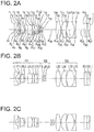
- Fig. 2A, Fig. 2B, and Fig. 2C are lens cross-sectional views of the objective optical system according to the example 1, where, Fig. 2A is a cross-sectional view in a normal observation state, Fig. 2B is a cross-sectional view in an intermediate state, and Fig. 2C is a cross-sectional view in a proximity magnifying observation state.
- the objective optical system of the example 1, as shown in Fig. 2A, Fig. 2B, and Fig. 2C , includes in order from an object side, a first lens group G1 having a positive refractive power, a second lens group G2 having a negative refractive power, and a third lens group G3 having a positive refractive power.
- the first lens group G1 includes a planoconcave negative lens L1 of which an object side is a flat surface, a positive meniscus lens L2 having a convex surface directed toward an image side, a negative meniscus lens L3 having a convex surface directed toward the image side, a positive meniscus lens L4 having a convex surface directed toward the image side, a positive meniscus lens L5 having a convex surface directed toward the image side, a biconvex positive lens L6, and a negative meniscus lens L7 having a convex surface directed toward the image side.
- the positive meniscus lens L2 and the negative meniscus lens L3 form a cemented lens having a negative refractive power.
- the biconvex positive lens L6 and the negative meniscus lens L7 form a cemented lens having a positive refractive power.
- the second lens group G2 includes a biconcave negative lens L8 and a positive meniscus lens L9 having a convex surface directed toward the object side.
- the biconcave negative lens L8 and the positive meniscus lens L9 form a cemented lens having a negative refractive power.
- An aperture stop S is disposed between the first lens group G1 and the second lens group G2. More elaborately, the aperture stop S is disposed nearest to an object in the second lens group G2.
- the third lens group G3 includes a biconvex positive lens L10, a positive meniscus lens L11 having a convex surface directed toward the object side, a planoconvex positive lens L12, and a planoconcave negative lens L13.
- the biconvex positive lens L12 and the planoconcave negative lens L13 form a cemented lens having a negative refractive power.
- a plane-parallel plate F1 is disposed on the image side of the planoconcave negative lens L1.
- a plane-parallel plate F2 and a cover glass CG are disposed on the image side of the third lens group G3.
- the second lens group G2 and the aperture stop S move integrally.
- the second lens group G2 and the aperture stop S move toward the image side.
- the objective optical system of the example 1 has the abovementioned basic arrangement, and satisfies each of conditional expressions (1) to (15). Moreover, by letting a focal length of each lens group from the first lens group G1 to the third lens group G3 to be an appropriate value, there is no degradation of image quality, and a compact objective optical system is realized.
- Fig. 3A, Fig. 3B, Fig. 3C, and Fig. 3D are aberration diagrams of a spherical aberration (SA), an astigmatism (AS), a distortion (DT), and a chromatic aberration of magnification (CC) respectively in the normal observation state of the example 1
- Fig. 3E, Fig. 3F, Fig. 3G, and Fig. 3H are aberration diagrams of a spherical aberration (SA), an astigmatism (AS), a distortion (DT), and a chromatic aberration of magnification (CC) respectively in the intermediate state of the example 1
- Fig. 3I, Fig. 3J, Fig. 3K, and Fig. 3L are aberration diagrams of a spherical aberration (SA), an astigmatism (AS), a distortion (DT), and a chromatic aberration of magnification (CC) respectively in the proximity magnifying observation state of the example 1.
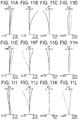
- a longitudinal axis indicates an aberration amount.
- the unit of aberration amount for the spherical aberration, the astigmatism, and the chromatic aberration of magnification is mm.
- the unit of aberration amount for the distortion is %.
- ⁇ is a half angle of view, and the unit of ⁇ is ° (degrees), and Fno denotes an F-number.
- the unit of a wavelength of an aberration curve is nm.
- Fig. 4A, Fig. 4B, and Fig. 4C are lens cross-sectional views of the objective optical system according to the example 2, where, Fig. 4A is a cross-sectional view in a normal observation state, Fig. 4B is a cross-sectional view in an intermediate state, and Fig. 4C is a cross-sectional view in a proximity magnifying observation state.
- the objective optical system of the example 2 includes in order from an object side, a first lens group G1 having a positive refractive power, a second lens group G2 having a negative refractive power, and a third lens group G3 having a positive refractive power.
- the first lens group G1 includes a planoconcave negative lens L1 of which an object side is a flat surface, a positive meniscus lens L2 having a convex surface directed toward an image side, a negative meniscus lens L3 having a convex surface directed toward the image side, a planoconvex positive lens L4 having a convex surface directed toward the image side, a negative meniscus lens L5 having a convex surface directed toward the image side, and a biconvex positive lens L6.
- the positive meniscus lens L2 and the negative meniscus lens L3 form a cemented lens having a positive refractive power.
- the planoconvex positive lens L4 and the negative meniscus lens L5 form a cemented lens having a positive refractive power.
- the second lens group G2 includes a biconcave negative lens L7 and a positive meniscus lens L8 having a convex surface directed toward the object side.
- the biconcave negative lens L7 and the positive meniscus lens L8 form a cemented lens having a negative refractive power.
- An aperture stop S is disposed between the first lens group G1 and the second lens group G2. More elaborately, the aperture stop S is disposed nearest to an object in the second lens group G2.
- the third lens group G3 includes a biconvex positive lens L9, a biconvex positive lens L10, and a negative meniscus lens L11 having a convex surface directed toward the image side.
- the biconvex positive lens L10 and the negative meniscus lens L11 form a cemented lens having a positive refractive power.
- a plane-parallel plate F1, a plane-parallel plate F2, and a cover glass CG are disposed on the image side of the third lens group G3.
- the second lens group G2 and the aperture stop S move integrally.
- the second lens group G2 and the aperture stop S move toward the image side.
- the objective optical system of the example 2 has the abovementioned basic arrangement, and satisfies each of conditional expressions (1) to (15). Moreover, by letting a focal length of each lens group from the first lens group G1 to the third lens group G3 to be an appropriate value, there is no degradation of image quality, and a compact objective optical system is realized.
- Fig. 5A, Fig. 5B, Fig. 5C, and Fig. 5D are aberration diagrams of a spherical aberration (SA), an astigmatism (AS), a distortion (DT), and a chromatic aberration of magnification (CC) respectively in the normal observation state of the example 2
- Fig. 5E, Fig. 5F, Fig. 5G, and Fig. 5H are aberration diagrams of a spherical aberration (SA), an astigmatism (AS), a distortion (DT), and a chromatic aberration of magnification (CC) respectively in the intermediate state of the example 2
- Fig. 5I, Fig. 5J, Fig. 5K, and Fig. 5L are aberration diagrams of a spherical aberration (SA), an astigmatism (AS), a distortion (DT), and a chromatic aberration of magnification (CC) respectively in the proximity magnifying observation state of the example 2.
- Fig. 6A, Fig. 6B, and Fig. 6C are lens cross-sectional views of the objective optical system according to the example 3, where, Fig. 6A is a cross-sectional view in a normal observation state, Fig. 6B is a cross-sectional view in an intermediate state, and Fig. 6C is a cross-sectional view in a proximity magnifying observation state.
- the objective optical system of the example 3, as shown in Fig. 6A, Fig. 6B, and Fig. 6C , includes in order from an object side, a first lens group G1 having a positive refractive power, a second lens group G2 having a negative refractive power, and a third lens group G3 having a positive refractive power.
- the first lens group G1 includes a planoconcave negative lens L1 of which an object side is a flat surface, a positive meniscus lens L2 having a convex surface directed toward an image side, a negative meniscus lens L3 having a convex surface directed toward the image side, a planoconvex positive lens L4 having a convex surface directed toward the image side, a negative meniscus lens L5 having a convex surface directed toward the image side, and a biconvex positive lens L6.
- the positive meniscus lens L2 and the negative meniscus lens L3 form a cemented lens having a positive refractive power.
- the planoconvex positive lens L4 and the negative meniscus lens L5 form a cemented lens having a positive refractive power.
- the second lens group G2 includes a biconcave negative lens L7 and a positive meniscus lens L8 having a convex surface directed toward the object side.
- the biconcave negative lens L7 and the positive meniscus lens L8 form a cemented lens having a negative refractive power.
- An aperture stop S is disposed between the first lens group G1 and the second lens group G2. More elaborately, the aperture stop S is disposed nearest to an object in the second lens group G2.
- the third lens group G3 includes a biconvex positive lens L9, a biconvex positive lens L10, and a planoconcave negative lens L11 of which an image side is a flat surface.
- a plane-parallel plate F1, a plane-parallel plate F2, and a cover glass CG are disposed on the image side of the third lens group G3.
- the second lens group G2 and the aperture stop S move integrally.
- the second lens group G2 and the aperture stop S move toward the image side.
- the objective optical system of the example 3 has the abovementioned basic arrangement, and satisfies each of conditional expressions (1) to (15). Moreover, by letting a focal length of each lens group from the first lens group G1 to the third lens group G3 to be an appropriate value, there is no degradation of image quality, and a compact objective optical system is realized.
- Fig. 7A, Fig. 7B, Fig. 7C, and Fig. 7D are aberration diagrams of a spherical aberration (SA), an astigmatism (AS), a distortion (DT), and a chromatic aberration of magnification (CC) respectively in the normal observation state of the example 3
- Fig. 7E, Fig. 7F, Fig. 7G, and Fig. 7H are aberration diagrams of a spherical aberration (SA), an astigmatism (AS), a distortion (DT), and a chromatic aberration of magnification (CC) respectively in the intermediate state of the example 3
- Fig. 7I, Fig. 7J, Fig. 7K, and Fig. 7L are aberration diagrams of a spherical aberration (SA), an astigmatism (AS), a distortion (DT), and a chromatic aberration of magnification (CC) respectively in the proximity magnifying observation state of the example 3.
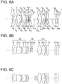
- Fig. 8A, Fig. 8B, and Fig. 8C are lens cross-sectional views of the objective optical system according to the example 4, where, Fig. 8A is a cross-sectional view in a normal observation state, Fig. 8B is a cross-sectional view in an intermediate state, and Fig. 8C is a cross-sectional view in a proximity magnifying observation state.
- the objective optical system of the example 4, as shown in Fig. 8A, Fig. 8B, and Fig. 8C , includes in order from an object side, a first lens group G1 having a positive refractive power, a second lens group G2 having a negative refractive power, and a third lens group G3 having a positive refractive power.
- the first lens group G1 includes a planoconcave negative lens L1 of which an object side is a flat surface, a biconvex positive lens L2, a negative meniscus lens L3 having a convex surface directed toward an image side, a positive meniscus lens L4 having a convex surface directed toward the image side, a negative meniscus lens L5 having a convex surface directed toward the image side, and a biconvex positive lens L6.
- the biconvex positive lens L2 and the negative meniscus lens L3 form a cemented lens having a positive refractive power.
- the positive meniscus lens L4 and the negative meniscus lens L5 form a cemented lens having a positive refractive power.
- the second lens group G2 includes a biconcave negative lens L7 and a positive meniscus lens L8 having a convex surface directed toward the object side.
- the biconcave negative lens L7 and the positive meniscus lens L8 form a cemented lens having a negative refractive power.
- An aperture stop S is disposed between the first lens group G1 and the second lens group G2. More elaborately, the aperture stop S is disposed nearest to an object in the second lens group G2.
- the third lens group G3 includes a biconvex positive lens L9, a biconvex positive lens L10, and a planoconcave negative lens L11 of which an image side is a flat surface.
- a plane-parallel plate F1, a plane-parallel plate F2, and a cover glass CG are disposed on the image side of the third lens group G3.
- the second lens group G2 and the aperture stop S move integrally.
- the second lens group G2 and the aperture stop S move toward the image side.
- the objective optical system of the example 4 has the abovementioned basic arrangement, and satisfies each of conditional expressions (1) to (15). Moreover, by letting a focal length of each lens group from the first lens group G1 to the third lens group G3 to be an appropriate value, there is no degradation of image quality, and a compact objective optical system is realized.
- Fig. 9A, Fig. 9B, Fig. 9C, and Fig. 9D are aberration diagrams of a spherical aberration (SA), an astigmatism (AS), a distortion (DT), and a chromatic aberration of magnification (CC) respectively in the normal observation state of the example 4
- Fig. 9E, Fig. 9F, Fig. 9G, and Fig. 9H are aberration diagrams of a spherical aberration (SA), an astigmatism (AS), a distortion (DT), and a chromatic aberration of magnification (CC) respectively in the intermediate state of the example 4
- Fig. 9I, Fig. 9J, Fig. 9K, and Fig. 9L are aberration diagrams of a spherical aberration (SA), an astigmatism (AS), a distortion (DT), and a chromatic aberration of magnification (CC) respectively in the proximity magnifying observation state of the example 4.
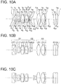
- Fig. 10A, Fig. 10B, and Fig. 10C are lens cross-sectional views of the objective optical system according to the example 5, where, Fig. 10A is a cross-sectional view in a normal observation state, Fig. 10B is a cross-sectional view in an intermediate state, and Fig. 10C is a cross-sectional view in a proximity magnifying observation state.
- the objective optical system of the example 5, as shown in Fig. 10A, Fig. 10B, and Fig. 10C , includes in order from an object side, a first lens group G1 having a positive refractive power, a second lens group G2 having a negative refractive power, and a third lens group G3 having a positive refractive power.
- the first lens group G1 includes a planoconcave negative lens L1 of which an object side is a flat surface, a positive meniscus lens L2 having a convex surface directed toward an image side, a negative meniscus lens L3 having a convex surface directed toward the image side, a biconvex positive lens L4, a negative meniscus lens L5 having a convex surface directed toward the image side, a biconvex positive lens L6, and a negative meniscus lens L7 having a convex surface directed toward the image side.
- the positive meniscus lens L2 and the negative meniscus lens L3 form a cemented lens having a positive refractive power.
- the biconvex positive lens L4 and the negative meniscus lens L5 form a cemented lens having a positive refractive power.
- the biconvex positive lens L6 and the negative meniscus lens L7 form a cemented lens having a positive refractive power.
- the second lens group G2 includes a biconcave negative lens L8 and a positive meniscus lens L9 having a convex surface directed toward the object side.
- the biconcave negative lens L8 and the positive meniscus lens L9 form a cemented lens having a negative refractive power.
- An aperture stop S is disposed between the first lens group G1 and the second lens group G2. More elaborately, the aperture stop S is disposed nearest to an object in the second lens group G2.
- the third lens group G3 includes a biconvex positive lens L10, a biconvex positive lens L11, and a negative meniscus lens L12 having a convex surface directed toward the image side.
- a plane-parallel plate F1 is disposed on the image side of the planoconcave negative lens L1.
- a plane-parallel plate F2 and a cover glass CG are disposed on the image side of the third lens group G3.
- the second lens group G2 and the aperture stop S move integrally.
- the second lens group G2 and the aperture stop S move toward the image side.
- the objective optical system of the example 5 has the abovementioned basic arrangement, and satisfies each of conditional expressions (1) to (15). Moreover, by letting a focal length of each lens group from the first lens group G1 to the third lens group G3 to be an appropriate value, there is no degradation of image quality, and a compact objective optical system is realized.
- Fig. 11A, Fig. 11B, Fig. 11C, and Fig. 11D are aberration diagrams of a spherical aberration (SA), an astigmatism (AS), a distortion (DT), and a chromatic aberration of magnification (CC) respectively in the normal observation state of the example 5
- Fig. 11E, Fig. 11F, Fig. 11G, and Fig. 11H are aberration diagrams of a spherical aberration (SA), an astigmatism (AS), a distortion (DT), and a chromatic aberration of magnification (CC) respectively in the intermediate state of the example 5
- Fig. 11I, Fig. 11J, Fig. 11K, and Fig. 11L are aberration diagrams of a spherical aberration (SA), an astigmatism (AS), a distortion (DT), and a chromatic aberration of magnification (CC) respectively in the proximity magnifying observation state of the example 5.
- Fig. 12A, Fig. 12B, and Fig. 12C are lens cross-sectional views of the objective optical system according to the example 6, where, Fig. 12A is a cross-sectional view in a normal observation state, Fig. 12B is a cross-sectional view in an intermediate state, and Fig. 12C is a cross-sectional view in a proximity magnifying observation state.
- the objective optical system of the example 6, as shown in Fig. 12A, Fig. 12B, and Fig. 12C , includes in order from an object side, a first lens group G1 having a positive refractive power, a second lens group G2 having a negative refractive power, and a third lens group G3 having a positive refractive power.
- the first lens group G1 includes a planoconcave negative lens L1 of which an object side is a flat surface, a positive meniscus lens L2 having a convex surface directed toward an image side, a negative meniscus lens L3 having a convex surface directed toward the image side, a positive meniscus lens L4 having a convex surface directed toward the image side, a negative meniscus lens L5 having a convex surface directed toward the image side, a biconvex positive lens L6, and a negative meniscus lens L7 having a convex surface directed toward the image side.
- the positive meniscus lens L2 and the negative meniscus lens L3 form a cemented lens having a positive refractive power.
- the positive meniscus lens L4 and the negative meniscus lens L5 form a cemented lens having a positive refractive power.
- the biconvex positive lens L6 and the negative meniscus lens L7 form a cemented lens having a positive refractive power.
- the second lens group G2 includes a biconcave negative lens L8 and a positive meniscus lens L9 having a convex surface directed toward the object side.
- the biconcave negative lens L8 and the positive meniscus lens L9 form a cemented lens having a negative refractive power.
- An aperture stop S is disposed between the first lens group G1 and the second lens group G2. More elaborately, the aperture stop S is disposed nearest to an object in the second lens group G2.
- the third lens group G3 includes a biconvex positive lens L10, a negative meniscus lens L11 having a convex surface directed toward the image side, a biconvex positive lens L12, and a planoconcave negative lens L13 of which an image side is a flat surface.
- the biconvex positive lens L10 and the negative meniscus lens L11 form a cemented lens having a positive refractive power.
- a plane-parallel plate F1, a plane-parallel plate F2, and a cover glass CG are disposed on the image side of the third lens group G3.
- the second lens group G2 and the aperture stop S move integrally.
- the second lens group G2 and the aperture stop S move toward the image side.
- the objective optical system of the example 6 has the abovementioned basic arrangement, and satisfies each of conditional expressions (1) to (15). Moreover, by letting a focal length of each lens group from the first lens group G1 to the third lens group G3 to be an appropriate value, there is no degradation of image quality, and a compact objective optical system is realized.
- Fig. 13A, Fig. 13B, Fig. 13C, and Fig. 13D are aberration diagrams of a spherical aberration (SA), an astigmatism (AS), a distortion (DT), and a chromatic aberration of magnification (CC) respectively in the normal observation state of the example 6
- Fig. 13E, Fig. 13F, Fig. 13G, and Fig. 13H are aberration diagrams of a spherical aberration (SA), an astigmatism (AS), a distortion (DT), and a chromatic aberration of magnification (CC) respectively in the intermediate state of the example 6
- Fig. 13I, Fig. 13J, Fig. 13K, and Fig. 13L are aberration diagrams of a spherical aberration (SA), an astigmatism (AS), a distortion (DT), and a chromatic aberration of magnification (CC) respectively in the proximity magnifying observation state of the example 6.
- Fig. 14A, Fig. 14B, and Fig. 14C are lens cross-sectional views of the objective optical system according to the example 7, where, Fig. 14A is a cross-sectional view in a normal observation state, Fig. 14B is a cross-sectional view in an intermediate state, and Fig. 14C is a cross-sectional view in a proximity magnifying observation state.
- the objective optical system of the example 7, as shown in Fig. 14A, Fig. 14B, and Fig. 14C , includes in order from an object side, a first lens group G1 having a positive refractive power, a second lens group G2 having a negative refractive power, and a third lens group G3 having a positive refractive power.
- the first lens group G1 includes a planoconcave negative lens L1 of which an object side is a flat surface, a positive meniscus lens L2 having a convex surface directed toward an image side, a positive meniscus lens L3 having a convex surface directed toward the image side, a negative meniscus lens L4 having a convex surface directed toward the image side, a biconvex positive lens L5, and a negative meniscus lens L6 having a convex surface directed toward the image side.
- the positive meniscus lens L3 and the negative meniscus lens L4 form a cemented lens having a positive refractive power.
- the biconvex positive lens L5 and the negative meniscus lens L6 form a cemented lens having a positive refractive power.
- the second lens group G2 includes a biconcave negative lens L7, a positive meniscus lens L8 having a convex surface directed toward the object side, and a negative meniscus lens L9 having a convex surface directed toward the object side.
- the biconcave negative lens L7 and the positive meniscus lens L8 form a cemented lens having a negative refractive power.
- An aperture stop S is disposed between the first lens group G1 and the second lens group G2. More elaborately, the aperture stop S is disposed nearest to an object in the second lens group G2.
- the third lens group G3 includes a biconvex positive lens L10, a biconvex positive lens L11, and a planoconcave negative lens L12 of which an image side is a flat surface.
- a plane-parallel plate F1, a plane-parallel plate F2, and a cover glass CG are disposed on the image side of the third lens group G3.
- the second lens group G2 and the aperture stop S move integrally.
- the second lens group G2 and the aperture stop S move toward the image side.
- the objective optical system of the example 7 has the abovementioned basic arrangement, and satisfies each of conditional expressions (1) to (15). Moreover, by letting a focal length of each lens group from the first lens group G1 to the third lens group G3 to be an appropriate value, there is no degradation of image quality, and a compact objective optical system is realized.
- Fig. 15A, Fig. 15B, Fig. 15C, and Fig. 15D are aberration diagrams of a spherical aberration (SA), an astigmatism (AS), a distortion (DT), and a chromatic aberration of magnification (CC) respectively in the normal observation state of the example 7
- Fig. 15E, Fig. 15F, Fig. 15G, and Fig. 15H are aberration diagrams of a spherical aberration (SA), an astigmatism (AS), a distortion (DT), and a chromatic aberration of magnification (CC) respectively in the intermediate state of the example 7,
- Fig. 15I, Fig. 15J, Fig. 15K, and Fig. 15L are aberration diagrams of a spherical aberration (SA), an astigmatism (AS), a distortion (DT), and a chromatic aberration of magnification (CC) respectively in the proximity magnifying observation state of the example 7.
- Fig. 16A, Fig. 16B, and Fig. 16C are lens cross-sectional views of the objective optical system according to the example 8, where, Fig. 16A is a cross-sectional view in a normal observation state, Fig. 16B is a cross-sectional view in an intermediate state, and Fig. 16C is a cross-sectional view in a proximity magnifying observation state.
- the objective optical system of the example 8, as shown in Fig. 16A, Fig. 16B, and Fig. 16C , includes in order from an object side, a first lens group G1 having a positive refractive power, a second lens group G2 having a negative refractive power, and a third lens group G3 having a positive refractive power.
- the first lens group G1 includes a planoconcave negative lens L1 of which an object side is a flat surface, a positive meniscus lens L2 having a convex surface directed toward an image side, a negative meniscus lens L3 having a convex surface directed toward the image side, a positive meniscus lens L4 having a convex surface directed toward the image side, a positive meniscus lens L5 having a convex surface directed toward the image side, a biconvex positive lens L6, and a negative meniscus lens L7 having a convex surface directed toward the image side.
- the positive meniscus lens L2 and the negative meniscus lens L3 form a cemented lens having a positive refractive power.
- the biconvex positive lens L6 and the negative meniscus lens L7 form a cemented lens having a positive refractive power.
- the second lens group G2 includes a biconcave negative lens L8 and a positive meniscus lens L9 having a convex surface directed toward the object side.
- the biconcave negative lens L8 and the positive meniscus lens L9 form a cemented lens having a negative refractive power.
- An aperture stop S is disposed between the first lens group G1 and the second lens group G2. More elaborately, the aperture stop S is disposed nearest to an object in the second lens group G2.
- the third lens group G3 includes a biconvex positive lens L10, a biconvex positive lens L11, a biconcave negative lens L12, a planoconvex positive lens L13, and a negative meniscus lens L14 having a convex surface directed toward the image side.
- the biconvex positive lens L11 and the planoconcave negative lens L12 form a cemented lens having a negative refractive power.
- a plane-parallel plate F1 is disposed on the image side of the planoconcave negative lens L1.
- a plane-parallel plate F2 and a cover glass CG are disposed on the image side of the third lens group G3.
- the second lens group G2 and the aperture stop S move integrally.
- the second lens group G2 and the aperture stop S move toward the image side.
- the objective optical system of the example 8 has the abovementioned basic arrangement, and satisfies each of conditional expressions (1) to (15). Moreover, by letting a focal length of each lens group from the first lens group G1 to the third lens group G3 to be an appropriate value, there is no degradation of image quality, and a compact objective optical system is realized.
- Fig. 17A, Fig. 17B, Fig. 17C, and Fig. 17D are aberration diagrams of a spherical aberration (SA), an astigmatism (AS), a distortion (DT), and a chromatic aberration of magnification (CC) respectively in the normal observation state of the example 8
- Fig. 17E, Fig. 17F, Fig. 17G, and Fig. 17H are aberration diagrams of a spherical aberration (SA), an astigmatism (AS), a distortion (DT), and a chromatic aberration of magnification (CC) respectively in the intermediate state of the example 8
- Fig. 17I, Fig. 17J, Fig. 17K, and Fig. 17L are aberration diagrams of a spherical aberration (SA), an astigmatism (AS), a distortion (DT), and a chromatic aberration of magnification (CC) respectively in the proximity magnifying observation state of the example 8.
- r denotes radius of curvature of each lens surface
- d denotes a distance between respective lens surfaces
- ne denotes a refractive index of each lens for e-line
- vd denotes an Abbe number for each lens
- Fno denotes an F number
- ⁇ denotes a half angle of view
- IH denotes an image height.
- focal length is a value for the e-line. More over, ⁇ denotes a lateral magnification of the overall objective optical system at a proximity magnifying observation state.
- Conditional expression Example1 Example2 Example3 Example4 (1) f f /f e 0.28 0.27 0.28 0.32 (2)
- the present invention also includes the following inventions which are conceived form abovementioned embodiments and examples.
- An objective optical system comprising in order from an object side; a first lens group having a positive refractive power, a second lens group having a negative refractive power, and a third lens group having a positive refractive power, wherein focusing is carried out by moving the second lens group with respect to a change in an object-point distance, and the following condition expression (1) is satisfied: 0 ⁇ f f / f e ⁇ 0.33 where,
- An objective optical system comprising in order from an object side; a first lens group having a positive refractive power, a second lens group having a negative refractive power, and a third lens group having a positive refractive power, wherein focusing is carried out by moving the second lens group with respect to a change in an object-point distance, and the following conditional expressions (2) and (3) are satisfied: 3 ⁇ ⁇ and 60 ° ⁇ ⁇ where,
- An objective optical system comprising in order from an object side; a first lens group having a positive refractive power, a second lens group having a negative refractive power, and a third lens group having a positive refractive power, wherein focusing is carried out by moving only the second lens group with respect to a change in an object-point distance, and the first lens group includes at least one negative lens, two cemented lenses, and one positive lens, and the negative lens is disposed nearest to an object, and the cemented lens includes a positive lens and a negative lens.
- the objective optical system according to any one of Appended Modes 1 to 3, wherein the objective optical system is used for an endoscope.
- the present invention is useful for an objective optical system in which the objective optical system is small-sized and with a large magnification at the time of proximity magnifying observation and macro photography, and has a high resolving power, while enabling to change an object-point distance to which the focusing can be done.
Landscapes
- Physics & Mathematics (AREA)
- Optics & Photonics (AREA)
- General Physics & Mathematics (AREA)
- Life Sciences & Earth Sciences (AREA)
- Health & Medical Sciences (AREA)
- Surgery (AREA)
- Astronomy & Astrophysics (AREA)
- Medical Informatics (AREA)
- General Health & Medical Sciences (AREA)
- Radiology & Medical Imaging (AREA)
- Nuclear Medicine, Radiotherapy & Molecular Imaging (AREA)
- Engineering & Computer Science (AREA)
- Biomedical Technology (AREA)
- Pathology (AREA)
- Molecular Biology (AREA)
- Heart & Thoracic Surgery (AREA)
- Animal Behavior & Ethology (AREA)
- Biophysics (AREA)
- Public Health (AREA)
- Veterinary Medicine (AREA)
- Lenses (AREA)
- Instruments For Viewing The Inside Of Hollow Bodies (AREA)
Abstract

ff denotes a front focal position at the time of focusing to an object point at a close distance, and
fe denotes a focal length of the overall objective optical system at the time of focusing to an object point at a close distance.
Description
- The present invention relates to an objective optical system having a focusing function, and in particular, to an objective optical system for endoscope that enables a proximity magnifying observation, an objective optical system of a digital camera and a video camera that enables macro photography or an objective optical system of a miniature camera for consumer use.
- In a field of medical endoscopes, precise diagnosis of a lesioned part has been carried out by an observation through an endoscope (hereinafter, referred to as 'endoscopic observation'). Therefore, an objective lens of an endoscope, in a state of being close to a lesioned part, is sought to enable magnifying observation of the lesioned part. As such objective lens, an objective lens in which it is possible to change an object-point distance (object distance) at which the focusing can be done (hereinafter, referred to as "magnifying endoscope objective lens'), is available.
- In the magnifying endoscope objective lens, by focusing to an object point at a close distance, it is possible to carry out proximity magnifying observation. Moreover, it is possible to carry out normal observation by focusing to an object point at a long distance. The normal observation is an observation with a magnification lower than a magnification in the proximity magnifying observation. In the normal observation, it is possible to observe a wide range including a lesioned part and a surrounding portion thereof. As the magnifying endoscope objective lens, magnifying endoscope objective lenses disclosed in
patent literatures 1 to 4 are available. - The magnifying endoscope objective lenses disclosed in
patent literatures 1 to 3 include a first lens group having a positive refractive power, a second lens group having a negative refractive power, and a third lens group having a positive refractive power. At the time of focusing to an object point at a close distance and an object point at a long distance, the second lens group having a negative refractive power moves. - The magnifying endoscope objective lens disclosed in
patent literature 4 includes a first lens group having a negative refractive power, a second lens group having a positive refractive power, and a third lens group having a negative refractive power. At the time of focusing to an object point at a close distance and an object point at a long distance, the second lens group having a positive refractive power moves. - In recent years, for improving an accuracy of diagnosis, a high quality of an endoscope image has been sought. In order to meet the requirement, a use of an image pickup element with number of pixels larger than the number of pixels of a conventional image pickup element has been started. Consequently, the magnifying endoscope objective lens is sought to have a high resolving power.
- Moreover, in precise diagnosis of a lesioned part in recent years, it has been strongly sought that an observation of same level as an observation through a microscope (hereinafter, referred to as 'microscopic observation') be carried out even by the endoscopic observation. The observation of same level as the microscopic observation means an observation with about same degree of magnification and resolving power. For this, the magnifying endoscope objective lens is sought to have even larger magnification at the time of proximity magnifying observation. By doing so, an observation of same level as the microscopic observation is possible even by an endoscope.
- In endoscopic observation, observation of a physiological tissue with the same level as the microscopic observation, such as an observation at the cellular level, has heretofore been difficult. Consequently, the only method available was to extract a part of a physiological tissue by biopsy after a lesioned part has been identified by endoscopic observation, and to observe the extracted physiological tissue by a microscope. However, by using a magnifying endoscope objective lens having a large magnification, there is a merit of being able to observe a physiological tissue with the same level as the microscopic observation while being in-vivo, as an extension of the normal observation.
- As an endoscope objective lens which enables observation of the same level as the microscopic observation, endoscope objective lenses disclosed in patent literatures 5 to 9 are available.
- The endoscope objective lenses disclosed in patent literatures 5 and 6 are single focal length endoscope objective lenses. A single focal length endoscope objective lens is an objective lens in which an object-point distance to which the focusing can be done has been determined in advance. Therefore, the endoscope objective lenses disclosed in patent literatures 5 and 6 do not include a lens group that moves.
- The endoscope objective lenses disclosed in
patent literatures 7 to 9 are magnifying endoscope objective lenses. - Two magnifying endoscope objective lenses have been disclosed in
patent literature 7. One magnifying endoscope objective lens includes a first lens group having a positive refractive power, a second lens group having a negative refractive power, and a third lens group having a positive refractive power. At the time of focusing to an object point at a close distance or an object point at a long distance, the second lens group having a negative refractive power moves. Moreover, the other magnifying endoscope objective lens includes a first lens group having a negative refractive power, a second lens group having a positive refractive power, and a third lens group having a positive refractive power. At the time of focusing to an object point at a close distance and an object point at a long distance, the second lens group having a positive refractive power moves. - The magnifying endoscope objective lens disclosed in patent literature 8 includes four lens groups. At the time of focusing to an object point at a close distance and an object point at a long distance, a second lens group and a third lens group move, or the third lens group moves.
- The magnifying endoscope objective lens disclosed in
patent literature 9 includes a first lens group having a positive refractive power, a second lens group having a negative refractive power, and a third lens group having a positive refractive power. At the time of focusing to an object point at a close distance and an object point at a long distance, the second lens group having a negative refractive power moves. -
- PTL 1: Japanese Patent Publication after Examination No. Sho
61-044283 - PTL 2: Japanese Patent Application Laid-open Publication No.
Hei 06-317744 - PTL 3: Japanese Patent Application Laid-open Publication No.
Hei 11-316339 - PTL 4: Japanese Patent Application Laid-open Publication No.
2000-267002 - PTL 5: Japanese Patent Application Laid-open Publication No.
2004-313769 - PTL 6: Japanese Patent Application Laid-open Publication No.
2004-313772 - PTL 7: Japanese Patent Application Laid-open Publication No.
2007-233036 - PTL 8: Japanese Patent Application Laid-open Publication No.
2007-260305 - PTL 9: Japanese Patent Application Laid-open Publication No.
2009-294496 - Moreover, a desire to carry out the proximity magnification observation with a high resolving power and enlarge magnification is there not only in endoscopes, but also in digital cameras and video cameras. The macro photography in digital cameras and video cameras corresponds to the proximity magnifying observation. Therefore, even in optical systems of digital cameras and video cameras, high magnification and high resolving power in the macro photography have been sought. Moreover, in optical systems of digital cameras and video cameras, small-sizing of an optical system is desired.
- In endoscopic observation, for finding a lesioned part, screening of inside of the body is to be carried out. In the magnifying endoscope objective lens disclosed in
patent literature 1, at the time of carrying out the screening, a field of view at the time of normal observation being narrow, a job of treating the lesioned part becomes difficult. Moreover, the resolving power at the time of proximity magnifying observation cannot be said to be adequate. - In the magnifying endoscope objective lenses disclosed in
patent literatures 2 to 4, the magnification at the time of proximity magnifying observation is not adequately high to enable the observation of same level as the microscopic observation. - In the single focal length endoscope objective lenses disclosed in patent literatures 5 and 6, the magnification at the time of observation is high. Therefore, in these single focal length endoscope objective lenses, the observation of same level as the microscopic observation is possible. However, the magnification being fixed in these single focal length endoscope objective lenses, it is possible to carry out only proximity magnifying observation. For such reasons, these single focal length endoscope objective lenses, in addition to an objective lens for carrying out the normal observation, are to be provided with an objective lens module separately for proximity magnifying observation.
- Therefore, at the time of carrying out proximity magnifying observation of a lesioned part by using the single focal length endoscope objective lenses disclosed in patent literatures 5 and 6, these single focal length endoscope objective lenses are to be guided up to a front end of an endoscope insertion portion (hereinafter, referred to as 'insertion portion') through a treatment-tool insertion channel of the endoscope. In this case, since each single focal length endoscope objective lens has a different optical axis with respect to an objective lens for normal observation, at the time of changing the method of observation from the normal observation to the proximity magnifying observation, a parallax occurs. As a result, it becomes difficult to specify an observation range at the time of proximity magnifying observation.
- Furthermore, since these single focal length endoscope objective lenses have to go through the treatment-tool insertion channel, a diameter thereof becomes thin. In this case, it becomes difficult to fix the single focal length endoscope objective lens with respect to a site to be observed. When the fixing of the single focal length endoscope objective lens is difficult, it is difficult to observe a magnified image stably. Therefore, endoscopes including the single focal length endoscope objective lens have not being used except by certain skilled experienced doctors having an observation technique.
- As a method of observing stably a magnified image in a state close to a site to be observed, a method of disposing two objective lenses in one insertion portion in advance separately from the treatment-tool insertion channel may be taken into consideration. However, the insertion portion used in this method is same as an insertion portion in which an insertion portion of an endoscope having an objective lens for normal observation and an insertion portion of an endoscope having an objective lens for proximity magnifying are put together. In this case, since an outer diameter of the insertion portion in particular becomes large, the stress that the patient has to bear is tremendous.
- In the magnifying endoscope objective lenses disclosed in
patent literatures 7 to 9, it is possible to carry out observation in a state further closer to a site to be observed than in the observation by the magnifying endoscope objective lenses disclosed in citedreferences 1 to 4. - However, in the magnifying endoscope objective lens disclosed in
patent literature 7, the magnification at the time of proximity magnifying observation being small, it is difficult to carry out observation of the same level as the microscopic observation. Therefore, when an observation by a monitor is intended, an electronic image magnification (hereinafter, referred to as 'electronic zoom') is to be used together in combination. As a result, the observation magnification becomes large but there is a possibility of degradation of image quality as the resolving power of image becomes low. - In the magnifying endoscope objective lenses disclosed in
patent literatures 8 and 9, the magnification at the time of proximity magnifying observation is a magnification that enables observation of the cellular level. However, in recent years, an observation of cell nucleus rather than the cellular observation has been sought. Therefore, the magnification at the time of proximity magnifying observation cannot be said to be adequate for the observation of cell nucleus. - In the magnifying endoscope objective lens disclosed in patent literature 8, at the time of switching between the normal observation and the proximity magnifying observation, two lens groups move. In this case, since it is necessary to install a drive mechanism having a complicated structure in the insertion portion, the insertion portion becomes large-sized. Moreover, since the two lens groups move completely independently, control of the movement becomes difficult.
- In such manner, a capability to carry out observation of the same level as the microscopic observation in the form of an extension of the proximity magnifying observation, and proximity magnifying observation with even higher magnification has been sought.
- The present invention has been made in view of such problems, and an object of the present invention is to provide an objective optical system having a high resolving power, which is small-sized and with a large magnification at the time of proximity magnifying observation and macro photography, while enabling to change an object-point distance to which the focusing can be done.
- To solve the abovementioned problems and to achieve an object, the present invention provides the following means.
- An objective optical system according to an aspect of the present invention comprises in order from an object side;
a first lens group having a positive refractive power, a second lens group having a negative refractive power, and a third lens group having a positive refractive power, wherein
focusing is carried out by moving the second lens group with respect to a change in an object-point distance, and the following conditional expression (1) is satisfied:
- ff denotes a front focal position at a time of focusing to an object point at a close distance, and
- fe denotes a focal length of the overall objective optical system at the time of focusing to the object point at the close distance.
- Moreover, an objective optical system according to another aspect of the present invention comprises in order from an object side;
a first lens group having a positive refractive power, a second lens group having a negative refractive power, and a third lens group having a positive refractive power, wherein
focusing is carried out by moving the second lens group with respect to a change in an object-point distance, and
the following conditional expressions (2) and (3) are satisfied:

- P denotes a lateral magnification of the overall objective optical system at a time of focusing to an object point at a close distance, and
- ω denotes a maximum half angle of view at the time of focusing to an object point at a long distance.
- Moreover, an objective optical system according to still another aspect of the present invention comprises in order from an object side;
a first lens group having a positive refractive power, a second lens group having a negative refractive power, and a third lens group having a positive refractive power, wherein
focusing is carried out by moving only the second lens group with respect to a change in an object-point distance, and
the first lens group includes at least one negative lens, two cemented lenses, and one positive lens, and
the negative lens is disposed nearest to an object, and
the cemented lens includes a positive lens and a negative lens. - Moreover, an objective optical system according to a preferable aspect of the present invention is to be used for an endoscope.
- An objective optical system according to an embodiment of the present invention shows an effect that the objective optical system is small-sized and with a large magnification at the time of proximity magnifying observation and macro photography, and has a high resolving power, while enabling to change an object-point distance to which the focusing can be done.
-
-
Fig. 1 is a diagram showing a cross-sectional arrangement of an objective optical system according to an embodiment of the present invention; -
Fig. 2A, Fig. 2B, and Fig. 2C are diagrams showing a cross-sectional arrangement of an objective optical system according to an example 1 of the present invention, where,Fig. 2A is a cross-sectional view in a normal observation state,Fig. 2B is a cross-sectional view in an intermediate state, andFig. 2C is a cross-sectional view in a proximity magnifying observation state; -
Fig. 3A, Fig. 3B, Fig. 3C, Fig. 3D, Fig. 3E, Fig. 3F, Fig. 3G, Fig. 3H, Fig. 3I, Fig. 3J, Fig. 3K, and Fig. 3L are aberrations diagrams showing a spherical aberration (SA), an astigmatism (AS), a distortion (DT), and a chromatic aberration of magnification (CC) of the example 1; -
Fig. 4A, Fig. 4B, and Fig. 4C are diagrams showing a cross-sectional arrangement of an objective optical system according to an example 2 of the present invention, where,Fig. 4A is a cross-sectional view in a normal observation state,Fig. 4B is a cross-sectional view in an intermediate state, andFig. 4C is a cross-sectional view in a proximity magnifying observation state; -
Fig. 5A, Fig. 5B, Fig. 5C, Fig. 5D, Fig. 5E, Fig. 5F, Fig. 5G, Fig. 5H, Fig. 5I, Fig. 5J, Fig. 5K, and Fig. 5L are aberration diagrams showing a spherical aberration (SA), an astigmatism (AS), a distortion (DT), and a chromatic aberration of magnification (CC) of the example 2; -
Fig. 6A, Fig. 6B, and Fig. 6C are diagrams showing a cross-sectional arrangement of an objective optical system according to an example 3 of the present invention, where,Fig. 6A is a cross-sectional view in a normal observation state,Fig. 6B is a cross-sectional view in an intermediate state, andFig. 6C is a cross-sectional view in a proximity magnifying observation state; -
Fig. 7A, Fig. 7B, Fig. 7C, Fig. 7D, Fig. 7E, Fig. 7F, Fig. 7G, Fig. 7H, Fig. 7I, Fig. 7J, Fig. 7K, and Fig. 7L are aberration diagrams showing a spherical aberration (SA), an astigmatism (AS), a distortion (DT), and a chromatic aberration of magnification (CC) of the example 3; -
Fig. 8A, Fig. 8B, and Fig. 8C are diagrams showing a cross-sectional arrangement of an objective optical system according to an example 4 of the present invention, where,Fig. 8A is a cross-sectional view in a normal observation state,Fig. 8B is a cross-sectional view in an intermediate state, andFig. 8C is a cross-sectional view in a proximity magnifying observation state; -
Fig. 9A, Fig. 9B, Fig. 9C, Fig. 9D, Fig. 9E, Fig. 9F, Fig. 9G, Fig. 9H, Fig. 9I, Fig. 9J, Fig. 9K, and Fig. 9L are aberration diagrams showing a spherical aberration (SA), an astigmatism (AS), a distortion (DT), and a chromatic aberration of magnification (CC) of the example 4; -
Fig. 10A, Fig. 10B, and Fig. 10C are diagrams showing a cross-sectional arrangement of an objective optical system according to an example 5 of the present invention, where,Fig. 10A is a cross-sectional view in a normal observation state,Fig. 10B is a cross-sectional view in an intermediate state, andFig. 10C is a cross-sectional view in a proximity magnifying observation state; -
Fig. 11A, Fig. 11B, Fig. 11C, Fig. 11D, Fig. 11E, Fig. 11F, Fig. 11G, Fig. 11H, Fig. 11I, Fig. 11J, Fig. 11K, and Fig. 11L are aberration diagrams showing a spherical aberration (SA), an astigmatism (AS), a distortion (DT), and a chromatic aberration of magnification (CC) of the example 5; -
Fig. 12A, Fig. 12B, and Fig. 12C are diagrams showing a cross-sectional arrangement of an objective optical system according to an example 6 of the present invention, where,Fig. 12A is a cross-sectional view in a normal observation state,Fig. 12B is a cross-sectional view in an intermediate state, andFig. 12C is a cross-sectional view in a proximity magnifying observation state; -
Fig. 13A, Fig. 13B, Fig. 13C, Fig. 13D, Fig. 13E, Fig. 13F, Fig. 13G, Fig. 13H, Fig. 13I, Fig. 13J, Fig. 13K, and Fig. 13L are aberration diagrams showing a spherical aberration (SA), an astigmatism (AS), a distortion (DT), and a chromatic aberration of magnification (CC) of the example 6; -
Fig. 14A, Fig. 14B, and Fig. 14C are diagrams showing a cross-sectional arrangement of an objective optical system according to an example 7 of the present invention, where,Fig. 14A is a cross-sectional view in a normal observation state,Fig. 14B is a cross-sectional view in an intermediate state, andFig. 14C is a cross-sectional view in a proximity magnifying observation state; -
Fig. 15A, Fig. 15B, Fig. 15C, Fig. 15D, Fig. 15E, Fig. 15F, Fig. 15G, Fig. 15H, Fig. 15I, Fig. 15J, Fig. 15K, and Fig. 15L are aberration diagrams showing a spherical aberration (SA), an astigmatism (AS), a distortion (DT), and a chromatic aberration of magnification (CC) of the example 7; -
Fig. 16A, Fig. 16B, and Fig. 16C are diagrams showing a cross-sectional arrangement of an objective optical system according to an example 8 of the present invention, where,Fig. 16A is a cross-sectional view in a normal observation state,Fig. 16B is a cross-sectional view in an intermediate state, andFig. 16C is a cross-sectional view in a proximity magnifying observation state; and -
Fig. 17A, Fig. 17B, Fig. 17C, Fig. 17D, Fig. 17E, Fig. 17F, Fig. 17G, Fig. 17H, Fig. 17I, Fig. 17J, Fig. 17K, and Fig. 17L are aberration diagrams showing a spherical aberration (SA), an astigmatism (AS), a distortion (DT), and a chromatic aberration of magnification (CC) of the example 8. - Reasons for adopting such arrangements and effects thereof in an objective optical system according to the present embodiment will be described below by referring to the accompanying diagrams. However, the present invention is not limited to the following embodiments.
- The objective optical system according to the present embodiment can be used for an objective lens of an endoscope. In this case, the objective optical system according to present embodiment, in endoscopic observation, enables to carry out normal observation and proximity magnifying observation with one optical system. For this, the objective optical system includes a plurality of lens groups, and at least one of the plurality of lens groups moves on an optical axis. Accordingly, it is possible to carry out the normal observation when focused to an object point at a long distance and the proximity magnifying observation when focused to an object point at a close distance. In other words, an observation of same level as microscopic observation in the form of an extension of the proximity magnifying observation, and proximity magnifying observation with even higher magnification are possible.
- A basic arrangement of the objective optical system according to the present embodiment will be described below. In the basic arrangement, the objective optical system includes in order from an obj ect side, a first lens group having a positive refractive power, a second lens group having a negative refractive power, and a third lens group having a positive refractive power. Moreover, focusing is carried out by moving the second lens group with respect to a change in an obj ect-point distance.
- The first lens group includes a single lens and a cemented lens. In the first lens group, at least one negative lens is to be used as the single lens. The negative lens is to be disposed nearest to an object. Moreover, in the first lens group, at least two cemented lenses are to be used as a cemented lens. In such manner, the first lens group includes at least one negative lens and two cemented lenses.
- In the first lens group, additionally one positive lens or two positive lenses may be used as a single lens. Moreover, in the first lens group, additionally one cemented lens may be used as the cemented lens.
- The second lens group includes one cemented lens. In the second lens group, additionally one negative lens may be used.
- The third lens group includes either only a single lens or a single lens and a cemented lens. The third lens group may include at the most three single lenses as the single lens. Moreover, in the third lens group, one cemented lens is used as the cemented lens.
- A specific arrangement of the objective optical system according to the present embodiment will be described below.
Fig. 1 is a diagram showing a cross-sectional arrangement of the objective optical system according to the present embodiment. - A first lens group G1 includes in order from an object side, a negative lens L1, a cemented lens CL1, a positive lens L4, a positive lens L5, and a cemented lens CL2. Here, the cemented lens CL1 includes a positive lens L2 and a negative lens L3. The cemented lens CL2 includes a positive lens L6 and a negative lens L7.
- If a single lens is let to be a unit, the first lens group G1 includes seven single lenses. A second lens from the object side becomes the positive lens L2 and a fourth lens from the object side becomes the positive lens L4.
- Whereas, if a lens component is let to be a unit, the first lens group G1 includes five lens components. A second lens component from the object side becomes the cemented lens CL1 and a fourth lens component from the object side becomes the positive lens L6. Here, a lens component means a single lens or a cemented lens.
- A second lens group G2 includes a cemented lens CL3. The cemented lens CL3 includes a negative lens L8 and a positive lens L9.
- Moreover, the second lens group G2 has an aperture stop S on the object side. By disposing the aperture stop S near the second lens group G2, it is possible to make low a height of a light ray that passes through the second lens group G2. As a result, it is possible to make an outer diameter of the second lens group G2 small.
- The second lens group G2 moves at the time of focusing. By the second lens group G2 moving, the focusing can be carried out even when an object point is positioned anywhere from a long distance up to a close distance. It is possible to carry out normal observation when focused to an object point at a long distance, and proximity magnifying observation when focused to an object point at a close distance.
-
Fig. 1 is a diagram in a state in which the object point is positioned between the long distance and the close distance, or other words, in an intermediate state. In a case of focusing to the object point positioned at the long distance, the second lens group G2 moves from the position inFig. 1 toward the object side. In a case of focusing to the object point positioned at the close distance, the second lens group moves from the position inFig. 1 toward an image side. - A moving mechanism is necessary for moving the second lens group G2 in an optical axial direction. As mentioned above, in the objective optical system according to the present embodiment, since it is possible make the second lens group G2 small-sized, it is possible to dispose easily the moving mechanism around the second lens group G2.
- Moreover, since the number of lens groups that move is one, it is possible to make the moving lens group light-weight. Consequently, it is possible to reduce a load applied on the moving mechanism. Furthermore, it is possible to make the moving mechanism simple.
- As the moving mechanism, for example, an actuator is available. The actuator is to be connected to a lens frame holding the second lens group G2, and accordingly a drive force is imparted to the lens frame.
- A third lens group G3 includes a positive lens L10, a positive lens L11, and a cemented lens CL4. The cemented lens CL4 includes a positive lens L12 and a negative lens L13.
- In the objective optical system according to the present embodiment, a plane-parallel plate F1 is disposed in the first lens group G1. The plane-parallel plate F1 is a filter for cutting light of a specific wavelength such as laser light of YAG laser (light of wavelength 1060 nm), laser light of semiconductor laser (light of wavelength 810 nm), or light of wavelength of near-infrared region. The plane-parallel plate F1 may be disposed in the second lens group G2, or in the third lens group G3, or on the image side of the third lens group G3.
- Moreover, a plane-parallel plate F2 and a cover glass CG are disposed on the image side of the third lens group G3. The cover glass CG is provided to an image pickup element for protecting an image pickup surface of the image pickup element. Since an image-side surface of the cover glass CG is an image plane I of the objective optical system, the image pickup element is disposed such that the image plane I and the image pickup surface coincide. An image pickup optical system is formed by the objective optical system and the image pickup element.
- The objective optical system according to a first embodiment has the abovementioned basic arrangement, and the following conditional expression (1) is satisfied:

- ff denotes a front focal position at a time of focusing to an object point at a close distance, and
- fe denotes a focal length of the overall objective optical system at the time of focusing to the object point at the close distance.
- Conditional expression (1) is related to the front focal position of the objective optical system at the time of focusing to the object point at the close distance, and is necessary for making large the magnification at the time of proximity magnifying observation. Here, ff denotes a distance from a lens surface nearest to an object of the objective optical system up to the front focal position.
- The object-point distance is a distance from the lens surface nearest to the object of the objective optical system up to an object point (an object to be observed). For making large the magnification at the time of the proximity magnifying observation by shortening the object-point distance, it is preferable to bring the front focal position as close as possible to the objective optical system. When the front focal position is separated apart from the objective optical system, the objective optical system cannot come closer to the object point by distance separated apart. Therefore, by making large the magnification at the time of the proximity magnifying observation, it is necessary to make small a distance from the front focal position up to the objective optical system.
- When exceeding an upper limit value of conditional expression (1), the front focal position is separated excessively apart from the objective optical system. Consequently, at the time of the proximity magnifying observation, desired magnification cannot be achieved. Therefore, it is not preferable to exceed the upper limit value of conditional expression (1).
- When falling below a lower limit value of conditional expression (1), the front focal position approaches excessively closer to the objective optical system. In this case, an object-side surface of the first lens L1 has to be made a concave surface. However, in a case of using the objective optical system in an endoscope, it is preferable that the object-side surface of the first lens L1 is either a convex surface or a flat surface. Therefore, it is not preferable to let the object-side surface of the first lens L1 to be the concave surface, or in other words, to fall below the lower limit value of conditional expression (1).
- An objective optical system according to a second embodiment has the abovementioned basic arrangement, and the following conditional expressions (2) and (3) are satisfied:


- β denotes a lateral magnification of the overall objective optical system at the time of focusing to an object point at a close distance, and
- ω denotes a maximum half angle of view at the time of focusing to an object point at a long distance.
- By observing a lesion occurred in a physiological tissue at a cellular level, it is possible to observe a phenomenon that appears specifically (hereinafter, referred to as 'specific phenomenon') when a healthy cell becomes cancerous for example. Specific phenomena include a disarray of cell arrangement, an abnormal thickening of cell nucleus, and an abnormal growth of capillary blood vessels surrounding a cell nucleus. For observing such specific phenomenon, at the time of the proximity magnifying observation, it is necessary to secure a magnification of same level as a microscopic observation. Moreover, it becomes indispensable to secure a resolving power of same level as the microscopic observation in a range from a few tens of µm2 to approximately 100µm2 within a field of view.
- In a case in which the objective optical system of the present embodiment is combined with an image pickup element in which the number of pixels is made large, since the objective optical system of the present embodiment satisfies conditional expression (2), the resolving power of a few µm up to approximately 10µm is achieved. Taking into consideration a case of observing by displaying an image on a 19 inch monitor, since magnification of about 400 times to 600 times can be achieved, the observation at the cellular level, and furthermore, the observation at a cell-nucleus level become possible. Accordingly, it is possible to observe the specific phenomenon accurately.
- In a case in which the magnification at the time of the proximity magnifying observation is large, an extremely narrow range is to be observed with a high magnification. Therefore, in the proximity magnifying observation, it is desirable to observe by dabbing a front-end portion of an insertion portion at the physiological tissue. By doing so, the objective optical system makes a contact with and is fixed to a site to be observed. Accordingly, since it is possible to prevent shaking, a stable image is achieved.
- In a case of not satisfying conditional expression (2), the magnification at the time of the proximity magnifying observation is inadequate. Compensating the inadequate magnification by using an electrical compensating means such as an electronic zoom may be taken in to consideration. However, if an image before carrying out the electronic zoom is not an image with an extremely small aberration, quality of image after carrying out the electronic zoom is degraded. An image with a degraded quality is not preferable as an image to be used for diagnosis of the lesion.
- Moreover, in the objective optical system according to the present embodiment, at the time of the proximity magnifying observation, observation of same level as the microscopic observation is possible. However, since it is necessary to carry out screening of inside of the body for finding a lesioned part, and moreover, to treat the lesioned part, it is necessary to secure a wide field of view at the time of normal observation.
- By satisfying conditional expression (3), it is possible to secure the wide field of view at the time of the normal observation. The field of view in this case is a field of view of same degree as of an objective optical system without the function of the proximity magnifying observation. Thus, by satisfying conditional expression (3), even with the objective optical system that enables the proximity magnifying observation, it is possible to secure a sufficiently wide field of view at the time of the normal observation. Consequently, it is possible to carry out screening, diagnosis, and treatment without any problem.
- An objective optical system according to a third embodiment has the abovementioned basic arrangement, and in which only the second lens group is to be moved, and the first lens group includes at least one negative lens, two cemented lenses, and one positive lens, and the negative lens is disposed nearest to an object, and the cemented lens includes a positive lens and a negative lens.
- The objective optical system according to the present embodiment, similarly as the objective optical system according to the first embodiment and the objective optical system according to the second embodiment, includes a first lens group having a positive refractive power, a second lens group having a negative refractive power, and a third lens group having a positive refractive power, and focusing is carried out by moving only the second lens group with respect to a change in an object-point distance.
- In such objective optical system, it is desired that the first lens group is formed by combining two cemented lenses and one positive lens. By using two cemented lenses, it is possible to correct a chromatic aberration adequately.
- Particularly, at the time of carrying out proximity magnifying observation, it is desired that an imaging performance of a lens group positioned on an object side of an aperture stop, or in other words, an imaging performance of the first lens group is favorable. In the proximity magnifying observation, enlarge magnification by a lens group positioned on the image side of the aperture stop is large. Therefore, it is necessary to correct favorably a longitudinal chromatic aberration in particular, in the first lens group. When a cemented lens is not disposed in the first lens group, chromatic blurring occurred in an image is spread largely at the time of the proximity magnifying observation. Therefore, it is not preferable not to dispose a cemented lens in the first lens group.
- Moreover, by using one positive lens, a part of the positive refractive power in the first lens group is imposed on the positive lens. For dispersing the positive refractive power in the first lens group, it is preferable to add one positive lens in the first lens group. By doing so, it is possible to suppress an occurrence of aberration.
- Moreover, in the objective optical systems according to the first embodiment to the third embodiment (hereinafter, referred to as 'objective optical systems according to the present embodiment'), it is desirable that the following conditional expressions (4) and (5) are satisfied:


- fG12w denotes a combined focal length of the first lens group and the second lens group at the time of focusing to the object point at the long distance,
- fG12e denotes a combined focal length of the first lens group and the second lens group at the time of focusing to the object point the a close distance,
- fe denotes a focal length of the overall objective optical system at the time of focusing to then object point at the long distance, and
- fw denotes the focal length of the overall objective optical system at the time of focusing to the object point at the close distance.
- Conditional expression (4) is related to the combined focal length of the first lens group and the second lens group at the time of normal observation. By satisfying conditional expression (4), it is possible to correct an astigmatism favorably.
- When falling below a lower limit value of conditional expression (4), a meridional image plane is substantially inclined toward a minus side. When exceeding an upper limit value of conditional expression (4), both the meridional image plane and a sagittal image plane are inclined toward a plus side. Therefore, exceeding the upper limit value of conditional expression (4) is not preferable.
- Conditional expression (5) is related to the astigmatism at the time of proximity magnifying observation and the magnification of the overall optical system. By satisfying conditional expression (5), it is possible to correct the astigmatism at the time of the proximity magnifying observation as well as to secure the magnification necessary as the optical system as a whole.
- When falling below a lower limit value of conditional expression (5), at the time of the proximity magnifying observation, since the meridional image plane is inclined toward the minus side and the sagittal image plane is inclined toward the plus side, there is an increase in the astigmatism. Therefore, falling below the lower limit value of conditional expression (5) is not preferable.
- When exceeding an upper limit value of conditional expression (5), although there is no deterioration of astigmatism, the magnification that is necessary for the optical system as a whole becomes low. Consequently, the desired magnification cannot be achieved in both the normal observation and the proximity magnifying observation. Therefore, exceeding the upper limit value of conditional expression (5) is not preferable.
- Furthermore, it is desirable that the following conditional expression (5') is satisfied instead of conditional expression (5):

- By satisfying conditional expression (5'), it is possible to correct more favorably the astigmatism at the time of the proximity magnifying observation as well as to secure adequately the magnification necessary for the optical system as a whole.
- Moreover, in the objective optical system according to the present embodiment, it is preferable that the following conditional expression (6) is satisfied:

- fG1L2 denotes a focal length of a lens alone, positioned second from the object side in the first lens group, and
- fw denotes the focal length of the overall objective optical system at the time of focusing to the object point at the long distance.
- In the objective optical system according to the present embodiment, a negative lens is disposed first and a positive lens is disposed second when counted from the object side. Such arrangement of the lenses exerts an effect of suppressing a fluctuation in a curvature of field at the time of the normal observation as well as the proximity magnifying observation.
- Moreover, with such lens arrangement, it is preferable that conditional expression (6) is satisfied. By satisfying conditional expression (6), it is possible to suppress further the fluctuation in the curvature of field at the time of the normal observation as well as the proximity magnifying observation.
- When falling below a lower limit value of conditional expression (6), the image plane at the time of the normal observation is inclined toward the plus side, and the image plane at the time of the proximity magnifying observation is inclined toward the minus side. When exceeding an upper limit value of conditional expression (6), the image plane at the time of the normal observation is inclined toward the minus side and the image plane at the time of the proximity magnifying observation is inclined toward the plus side. Even when the positive lens is a single lens, it may be cemented with a negative lens positioned on the image side.
- Moreover, in the objective optical system according to the present embodiment, it is preferable that the following conditional expression (7) is satisfied:

- HF denotes a front principal-point position at the time of focusing to the object point at the close distance, and
- fe denotes the focal length of the overall objective optical system at the time of focusing to the object point at the close distance.
- Conditional expression (7) is related to the front principal-point position at the time of focusing to the object point at the close distance. By satisfying conditional expression (7), it is possible to secure the magnification necessary for the proximity magnifying observation. Here, HF is a distance from a lens surface nearest to object of the objective optical system up to the front principal-point position.
- When falling below a lower limit value of conditional expression (7), although the magnification at the time of the proximity magnifying observation becomes large, it is necessary to make large a refractive power of an image-side surface of the negative lens disposed nearest to the object. Since the refractive power of the first lens group is a positive refractive power, for maintaining the positive refractive power of each lens in the first lens group, there arises a need to make large the refractive power of the positive lens in particular. Consequently, from the normal observation up to the proximity magnifying observation, a spherical aberration and the curvature of field become large. Therefore, falling below the lower limit value of conditional expression (7) is not preferable.
- When exceeding an upper limit value of conditional expression (7), it becomes difficult to increase the magnification at the time of the proximity magnifying observation to the desired magnification.
- Moreover, in the objective optical system according to the present embodiment, it is desirable that the following conditional expression (8) is satisfied:

- fG1L4 denotes a focal length of a lens component positioned fourth from the object side in the first lens group, and
- fw denotes the focal length of the overall objective optical system at the time of focusing to the object point at the long distance, and here
- Conditional expression (8) is related to the focal length of the lens component positioned fourth from the object side, out of the lens components in the first lens group. Here, the lens component means either a single lens or a cemented lens.
- The lens component positioned fourth from the object side may be a single lens or may be a cemented lens, and in either of the cases, the lens component positioned fourth from the object side has a positive refractive power and is involved in correction of a chromatic aberration of magnification. By satisfying conditional expression (8), it is possible to correct the chromatic aberration of magnification favorably.
- When falling below a lower limit value of conditional expression (8), the chromatic aberration of magnification of higher-order about an F-line and a g-line, and particularly the chromatic aberration of magnification of higher-order about the g-line occurs substantially on the minus side, and the chromatic aberration of magnification of higher-order about a C-line occurs substantially on the plus side.
- When exceeding an upper limit value of conditional expression (8), the chromatic aberration of magnification of higher-order about the F-line and the g-line occurs substantially on the plus side, and the chromatic aberration of magnification of higher-order about the C-line occurs substantially on the minus side. In such manner, when the chromatic aberration of magnification of higher-order for each wavelength occurs substantially, it becomes a cause of chromatic blurring in a peripheral area of image. At the time of the proximity magnifying observation, since the occurrence of chromatic blurring in the peripheral area of image becomes substantial, the resolving power is degraded in the peripheral area of image. Therefore, exceeding the upper limit value of conditional expression (8) is not preferable.
- Furthermore, it is desirable that the following conditional expression (8') is satisfied instead of conditional expression (8):

- By satisfying conditional expression (8'), it is possible to correct more favorably the chromatic aberration of magnification at the time of the proximity magnifying observation.
- Moreover, in the objective optical system according to the present embodiment, it is desirable that the following conditional expression (9) is satisfied:

- fG1 denotes a focal length of the first lens group, and
- fG2 denotes a focal length of the second lens group.
- Conditional expression (9) is related to a ratio of the focal length of the first lens group and the focal length of the second lens group, and is related to correction of the spherical aberration and the chromatic aberration. By satisfying conditional expression (9), it is possible to correct favorably the spherical aberration and the chromatic aberration.
- In a case in which conditional expression (9) is not satisfied, the chromatic aberration of magnification cannot be corrected favorably. As a result, it leads to degradation of image quality, and particularly degradation of image quality in the peripheral area of image.
- When falling below a lower limit value of conditional expression (9) and the refractive power of second lens group becomes relatively too large as compared to the refractive power of the first lens group, the chromatic aberration of magnification about the C-line occurs substantially on the minus side, and the chromatic aberration of magnification about the F-line occurs substantially on the plus side. Furthermore, since the spherical aberration occurs substantially on the plus side, this leads to degradation of the resolving power. Therefore, falling below the lower limit value of conditional expression (9) is not preferable.
- When exceeding an upper limit value of conditional expression (9), and the refractive power of second lens group becomes relatively too small as compared to the refractive power of the first lens group, conversely, the chromatic aberration of magnification about the C-line occurs substantially on the plus side, and the chromatic aberration of magnification about the F-line occurs substantially on the minus side. Therefore, exceeding the upper limit value of conditional expression (9) is not preferable.
- When falling below the lower limit value of conditional expression (9), there is an effect also on the spherical aberration and the longitudinal chromatic aberration. Particularly, since the spherical aberration occurs significantly for a light ray of a low height, an aberration curve is substantially inclined toward the minus side. Moreover, with regard to the longitudinal chromatic aberration, the longitudinal chromatic aberration about the F-line is corrected excessively. Also, correction of coma becomes difficult. Therefore, falling below the lower limit value of conditional expression (9) is not preferable.
- Moreover, in the objective optical system according to the present embodiment, it is desirable that the following conditional expression (10) is satisfied:

- fG2 denotes the focal length of the second lens group, and
- fG3 denotes a focal length of the third lens group.
- Conditional expression (10) is related to a ratio of the focal length of the second lens group and the focal length of the third lens group. As to whether the refractive power of the second lens group is large or small depends on whether an amount of movement of the second lens group at the time of focusing is large or small. By satisfying conditional expression (10), it is possible to make the optical system small-sized as well as to suppress a fluctuation in aberration at the time of focusing.
- When falling below a lower limit value of conditional expression (10), since the refractive power of the second lens group becomes small, the amount of movement of the second lens group at the time of focusing becomes large. Consequently, the optical system becomes large-sized. Moreover, a stroke of driving a lens becomes long. Therefore, in a case of using an actuator in particular as a means for driving the lens, a drive mechanism including the actuator becomes large-sized. Moreover, while moving the lens, since it is necessary to move the lens through a long distance accurately, the drive mechanism is susceptible to become complicated.
- When exceeding an upper limit value of conditional expression (10) and the refractive power of the second lens group has become relatively large as compared to the refractive power of the third lens group, error sensitivity at the time of manufacturing becomes large. In the second lens group, a clearance between frames has been provided for the movement. In this case, relative positions of frames fluctuate within the range of clearance. Fluctuation in aberration occurs due to the relative fluctuation of frames, but when the error sensitivity at the time of manufacturing is high, the fluctuation in aberration becomes large. Therefore, exceeding the upper limit value of conditional expression (10) is not preferable.
- Furthermore, when exceeding the upper limit value of conditional expression (10), since the focal length of the third lens group becomes large, a back focus of the objective optical system becomes long. Consequently, an overall length of the optical system becomes long, and moreover, an overall length of an image pickup unit including an image pickup element becomes long. In such manner, the objective optical lens and the image pickup unit become large-sized. Therefore, exceeding the upper limit value of conditional expression (10) is not preferable.
- Moreover, in the objective optical system according to the present embodiment, it is preferable that the following conditional expression (11) is satisfied:

- ENw denotes a most diagonal entrance-pupil position at the time of focusing to the object point at the long distance, and
- ENe denotes a most diagonal entrance-pupil position at the time of focusing to the object point at the close distance.
- Conditional expression (11) is related to a position of an entrance pupil at a maximum diagonal, and particularly to a field of view at the time of focusing to the object point at the close distance. Here, ENw is a distance from a lens surface nearest to the object of the objective optical system up to the most diagonal entrance-pupil position at the time of focusing to the object point at the long distance and ENe is a distance from the lens surface nearest to obj ect of the objective optical system up to the most diagonal entrance-pupil position at the time of focusing to the object point at the close distance.
- When falling below a lower limit value of conditional expression (11), the entrance pupil at the time of focusing to the object point at the close distance is positioned on the object side. Therefore, the field of view at the time of focusing to the object point at the close distance becomes wide. However, since the magnification becomes small by an amount equivalent to an amount by which the field of view has widened, it becomes difficult to secure the magnification necessary for the proximity magnifying observation.
- When exceeding an upper limit value of conditional expression (11) and the entrance pupil at the time of focusing to the object point at the close distance is positioned on the image side, the field of view is narrowed excessively. Particularly, at the time of the proximity magnifying observation, a range of only a few µm2 to tens of 10µm2 in the field of view can be secured. Therefore, even for slightly improving the observability, it is necessary to secure the field of view of a certain width. Therefore, exceeding the upper limit value of conditional expression (11) is not preferable, and it is desirable to satisfy conditional expression (11).
- In the objective optical system according to the present embodiment, it is desirable that the following conditional expression (12) is satisfied:

- ENw denotes the most diagonal entrance-pupil position at the time of focusing to the object point at the long distance, and
- fw denotes the focal length of the overall objective optical system at the time of focusing to the object point at the long distance.
- Conditional expression (12) is related to the position of the entrance pupil at a maximum diagonal, and to an outer diameter of the lens system.
- When falling below a lower limit value of conditional expression (12), the entrance pupil at the maximum diagonal, at the time of focusing to the object point at the long distance, is positioned on the image side. Consequently, it is possible to make small a diameter of the lens positioned nearest to the object. However, since this leads to an increase in a diameter of the lens positioned nearest to the image, the optical system becomes large-sized. Therefore, falling below the lower limit value of conditional expression (12) is not preferable.
- When exceeding an upper limit value of conditional expression (12), the entrance pupil at the maximum diagonal, at the time of focusing to the object point at the long distance, is positioned on the object side. Consequently, the diameter of the lens positioned on the object side becomes large.
- Moreover, in the objective optical system according to the present embodiment, it is preferable that the following conditional expression (13) is satisfied:

- R3GLi denotes a radius of curvature on the object side of a lens positioned nearest to an image in the third lens group, and
- fe denotes the focal length of the objective optical system at the time of focusing to the object point at the close distance.
- Conditional expression (13) is related to the lens positioned nearest to the image in the third lens group. Conditional expression (13) is related to the correction of the longitudinal chromatic aberration and the curvature of field.
- When falling below a lower limit value of conditional expression (13), the refractive power of a negative lens positioned nearest to the image becomes large. Consequently, in the normal observation and the proximity magnifying observation, a fluctuation in an image plane, for example, a fluctuation in a position of the image plane and a fluctuation in an inclination of the image plane become large. Therefore, falling below the lower limit value of conditional expression (13) is not preferable.
- When exceeding an upper limit value of conditional expression (13), the refractive power of the negative lens positioned nearest to the image becomes small. In this case, the capacity of correcting chromatic aberration is reduced. Consequently, deterioration of the longitudinal chromatic aberration becomes remarkable. In other words, at the time of the normal observation, the longitudinal chromatic aberration about the C-line occurs substantially on the minus side and the longitudinal chromatic aberration about the F-line occurs substantially on the plus side. Whereas, at the time of the proximity magnifying observation, the longitudinal chromatic aberration about the C-line occurs substantially on the plus side, and the longitudinal chromatic aberration about the F-line occurs substantially on the minus side. In both the observations, the resolving power at an image center is degraded. Therefore, exceeding the upper limit value of conditional expression (13) is not preferable.
- Moreover, in the objective optical system according to the present embodiment, it is desirable that the following conditional expression (14) is satisfied.

- fG2 denotes the focal length of the second lens group, and
- fw denotes the focal length of the overall objective optical system at the time of focusing to the object point at the long distance.
- When falling below a lower limit value of conditional expression (14), in all observation states from the normal observation to the proximity magnifying observation, the image plane is inclined toward the plus side. Therefore, falling below the lower limit value of conditional expression (14) is not preferable.
- When an upper limit value of conditional expression (14) is exceeded, in all observation states from the normal observation to the proximity magnifying observation, correction of the spherical aberration is excessive. Therefore, exceeding the upper limit value of conditional expression (14) is not preferable.
- Moreover, in the objective optical system according to the present embodiment, it is desirable that the following conditional expression (15) is satisfied:

- Δ2G denotes an amount of movement of the second lens group when focused from the object point at the long distance to the object point at the close distance, and
- LTL denotes a overall length of the objective optical system.
- When falling below the lower limit value of conditional expression (15) and the amount of movement of the second lens group becomes small, a focusing sensitivity becomes excessively high. Therefore, falling below the lower limit value of conditional expression (15) is not preferable. Particularly, in a case in which the object point is at a position of a state close to the proximity magnifying observation, when the second lens group is moved even slightly, an imaging surface moves immediately. Thus, when falling below the lower limit value of conditional expression (15), the objective optical system becomes an optical system in which focusing becomes difficult.
- When exceeding an upper limit value of conditional expression (15), the amount of movement of the second lens group becomes excessively large. The overall length of the optical system becomes long due to the excessively large amount of movement of the second lens group. Therefore, exceeding the upper limit value of conditional expression (15) is not preferable.
- Moreover, in the objective optical system according to the present embodiment, it is desirable that a diameter of the aperture stop is constant when the aperture stop moves along the optical axis.
- In an aperture stop in which an aperture diameter changes, a mechanism which changes the aperture diameter is necessary. Since a driving means (such as an actuator) for driving the second lens has already been disposed in the insertion portion, installing such mechanism leads to further increase in diameter of a lens frame which accommodates the objective optical system. Therefore, it is not preferable to use an aperture stop of which the aperture diameter changes.
- Moreover, the objective optical system according to the present embodiment can also be used in an optical instrument other than endoscope.
- For instance, in an image pickup optical system of a digital camera, it is possible to use the objective optical system according to the present embodiment. In photography by a digital camera, sometimes macro photography beyond equal magnification is carried out. In such case, as an amount of drawing out of lens becomes large, a macro-converter lens is used in many cases. However, by using the objective optical system according to the present embodiment as an image pickup optical system, without installing the macro-converter lens, it is possible to carry out macro photography with a higher magnification than ever before.
- Moreover, generally, in a macro lens, the first lens group is drawn out toward the object side, and focusing is carried out by floating of a plurality of lens groups. However, when the objective optical system according to the present embodiment is used, macro photography with inner focusing is possible. Therefore, it is advantageous in a case of photographing after determining a working distance.
- Furthermore, the objective optical system according to the present embodiment can also be used for an image pickup optical system of portable equipment such as a camera of a mobile telephone. By doing so, the macro photography is readily enjoyable.
- An objective optical system according to an example 1 will be described below.
Fig. 2A, Fig. 2B, and Fig. 2C are lens cross-sectional views of the objective optical system according to the example 1, where,Fig. 2A is a cross-sectional view in a normal observation state,Fig. 2B is a cross-sectional view in an intermediate state, andFig. 2C is a cross-sectional view in a proximity magnifying observation state. - The objective optical system of the example 1, as shown in
Fig. 2A, Fig. 2B, and Fig. 2C , includes in order from an object side, a first lens group G1 having a positive refractive power, a second lens group G2 having a negative refractive power, and a third lens group G3 having a positive refractive power. - The first lens group G1 includes a planoconcave negative lens L1 of which an object side is a flat surface, a positive meniscus lens L2 having a convex surface directed toward an image side, a negative meniscus lens L3 having a convex surface directed toward the image side, a positive meniscus lens L4 having a convex surface directed toward the image side, a positive meniscus lens L5 having a convex surface directed toward the image side, a biconvex positive lens L6, and a negative meniscus lens L7 having a convex surface directed toward the image side. Here, the positive meniscus lens L2 and the negative meniscus lens L3 form a cemented lens having a negative refractive power. The biconvex positive lens L6 and the negative meniscus lens L7 form a cemented lens having a positive refractive power.
- The second lens group G2 includes a biconcave negative lens L8 and a positive meniscus lens L9 having a convex surface directed toward the object side. Here, the biconcave negative lens L8 and the positive meniscus lens L9 form a cemented lens having a negative refractive power.
- An aperture stop S is disposed between the first lens group G1 and the second lens group G2. More elaborately, the aperture stop S is disposed nearest to an object in the second lens group G2.
- The third lens group G3 includes a biconvex positive lens L10, a positive meniscus lens L11 having a convex surface directed toward the object side, a planoconvex positive lens L12, and a planoconcave negative lens L13. Here, the biconvex positive lens L12 and the planoconcave negative lens L13 form a cemented lens having a negative refractive power.
- A plane-parallel plate F1 is disposed on the image side of the planoconcave negative lens L1. A plane-parallel plate F2 and a cover glass CG are disposed on the image side of the third lens group G3.
- At the time of focusing, the second lens group G2 and the aperture stop S move integrally. When focusing is carried out from a state of being focused to an object point at a long distance to an object point at a close distance, the second lens group G2 and the aperture stop S move toward the image side.
- The objective optical system of the example 1 has the abovementioned basic arrangement, and satisfies each of conditional expressions (1) to (15). Moreover, by letting a focal length of each lens group from the first lens group G1 to the third lens group G3 to be an appropriate value, there is no degradation of image quality, and a compact objective optical system is realized.
-
Fig. 3A, Fig. 3B, Fig. 3C, and Fig. 3D are aberration diagrams of a spherical aberration (SA), an astigmatism (AS), a distortion (DT), and a chromatic aberration of magnification (CC) respectively in the normal observation state of the example 1,Fig. 3E, Fig. 3F, Fig. 3G, and Fig. 3H are aberration diagrams of a spherical aberration (SA), an astigmatism (AS), a distortion (DT), and a chromatic aberration of magnification (CC) respectively in the intermediate state of the example 1, andFig. 3I, Fig. 3J, Fig. 3K, and Fig. 3L are aberration diagrams of a spherical aberration (SA), an astigmatism (AS), a distortion (DT), and a chromatic aberration of magnification (CC) respectively in the proximity magnifying observation state of the example 1. - In each aberration diagram, a longitudinal axis indicates an aberration amount. The unit of aberration amount for the spherical aberration, the astigmatism, and the chromatic aberration of magnification is mm. Moreover, the unit of aberration amount for the distortion is %. Furthermore, ω is a half angle of view, and the unit of ω is ° (degrees), and Fno denotes an F-number. The unit of a wavelength of an aberration curve is nm. These symbols are same in other examples as well.
- An objective optical system according to an example 2 will be described below.
Fig. 4A, Fig. 4B, and Fig. 4C are lens cross-sectional views of the objective optical system according to the example 2, where,Fig. 4A is a cross-sectional view in a normal observation state,Fig. 4B is a cross-sectional view in an intermediate state, andFig. 4C is a cross-sectional view in a proximity magnifying observation state. - The objective optical system of the example 2, as shown in
Fig. 4A, Fig. 4B, and Fig. 4C , includes in order from an object side, a first lens group G1 having a positive refractive power, a second lens group G2 having a negative refractive power, and a third lens group G3 having a positive refractive power. - The first lens group G1 includes a planoconcave negative lens L1 of which an object side is a flat surface, a positive meniscus lens L2 having a convex surface directed toward an image side, a negative meniscus lens L3 having a convex surface directed toward the image side, a planoconvex positive lens L4 having a convex surface directed toward the image side, a negative meniscus lens L5 having a convex surface directed toward the image side, and a biconvex positive lens L6. Here, the positive meniscus lens L2 and the negative meniscus lens L3 form a cemented lens having a positive refractive power. The planoconvex positive lens L4 and the negative meniscus lens L5 form a cemented lens having a positive refractive power.
- The second lens group G2 includes a biconcave negative lens L7 and a positive meniscus lens L8 having a convex surface directed toward the object side. Here, the biconcave negative lens L7 and the positive meniscus lens L8 form a cemented lens having a negative refractive power.
- An aperture stop S is disposed between the first lens group G1 and the second lens group G2. More elaborately, the aperture stop S is disposed nearest to an object in the second lens group G2.
- The third lens group G3 includes a biconvex positive lens L9, a biconvex positive lens L10, and a negative meniscus lens L11 having a convex surface directed toward the image side. Here, the biconvex positive lens L10 and the negative meniscus lens L11 form a cemented lens having a positive refractive power.
- A plane-parallel plate F1, a plane-parallel plate F2, and a cover glass CG are disposed on the image side of the third lens group G3.
- At the time of focusing, the second lens group G2 and the aperture stop S move integrally. When focusing is carried out from a state of being focused to an object point at a long distance to an object point at a close distance, the second lens group G2 and the aperture stop S move toward the image side.
- The objective optical system of the example 2 has the abovementioned basic arrangement, and satisfies each of conditional expressions (1) to (15). Moreover, by letting a focal length of each lens group from the first lens group G1 to the third lens group G3 to be an appropriate value, there is no degradation of image quality, and a compact objective optical system is realized.
-
Fig. 5A, Fig. 5B, Fig. 5C, and Fig. 5D are aberration diagrams of a spherical aberration (SA), an astigmatism (AS), a distortion (DT), and a chromatic aberration of magnification (CC) respectively in the normal observation state of the example 2,Fig. 5E, Fig. 5F, Fig. 5G, and Fig. 5H are aberration diagrams of a spherical aberration (SA), an astigmatism (AS), a distortion (DT), and a chromatic aberration of magnification (CC) respectively in the intermediate state of the example 2, andFig. 5I, Fig. 5J, Fig. 5K, and Fig. 5L are aberration diagrams of a spherical aberration (SA), an astigmatism (AS), a distortion (DT), and a chromatic aberration of magnification (CC) respectively in the proximity magnifying observation state of the example 2. - An objective optical system according to an example 3 will be described below.
Fig. 6A, Fig. 6B, and Fig. 6C are lens cross-sectional views of the objective optical system according to the example 3, where,Fig. 6A is a cross-sectional view in a normal observation state,Fig. 6B is a cross-sectional view in an intermediate state, andFig. 6C is a cross-sectional view in a proximity magnifying observation state. - The objective optical system of the example 3, as shown in
Fig. 6A, Fig. 6B, and Fig. 6C , includes in order from an object side, a first lens group G1 having a positive refractive power, a second lens group G2 having a negative refractive power, and a third lens group G3 having a positive refractive power. - The first lens group G1 includes a planoconcave negative lens L1 of which an object side is a flat surface, a positive meniscus lens L2 having a convex surface directed toward an image side, a negative meniscus lens L3 having a convex surface directed toward the image side, a planoconvex positive lens L4 having a convex surface directed toward the image side, a negative meniscus lens L5 having a convex surface directed toward the image side, and a biconvex positive lens L6. Here, the positive meniscus lens L2 and the negative meniscus lens L3 form a cemented lens having a positive refractive power. The planoconvex positive lens L4 and the negative meniscus lens L5 form a cemented lens having a positive refractive power.
- The second lens group G2 includes a biconcave negative lens L7 and a positive meniscus lens L8 having a convex surface directed toward the object side. Here, the biconcave negative lens L7 and the positive meniscus lens L8 form a cemented lens having a negative refractive power.
- An aperture stop S is disposed between the first lens group G1 and the second lens group G2. More elaborately, the aperture stop S is disposed nearest to an object in the second lens group G2.
- The third lens group G3 includes a biconvex positive lens L9, a biconvex positive lens L10, and a planoconcave negative lens L11 of which an image side is a flat surface.
- A plane-parallel plate F1, a plane-parallel plate F2, and a cover glass CG are disposed on the image side of the third lens group G3.
- At the time of focusing, the second lens group G2 and the aperture stop S move integrally. When focusing is carried out from a state of being focused to an object point at a long distance to an object point at a close distance, the second lens group G2 and the aperture stop S move toward the image side.
- The objective optical system of the example 3 has the abovementioned basic arrangement, and satisfies each of conditional expressions (1) to (15). Moreover, by letting a focal length of each lens group from the first lens group G1 to the third lens group G3 to be an appropriate value, there is no degradation of image quality, and a compact objective optical system is realized.
-
Fig. 7A, Fig. 7B, Fig. 7C, and Fig. 7D are aberration diagrams of a spherical aberration (SA), an astigmatism (AS), a distortion (DT), and a chromatic aberration of magnification (CC) respectively in the normal observation state of the example 3,Fig. 7E, Fig. 7F, Fig. 7G, and Fig. 7H are aberration diagrams of a spherical aberration (SA), an astigmatism (AS), a distortion (DT), and a chromatic aberration of magnification (CC) respectively in the intermediate state of the example 3, andFig. 7I, Fig. 7J, Fig. 7K, and Fig. 7L are aberration diagrams of a spherical aberration (SA), an astigmatism (AS), a distortion (DT), and a chromatic aberration of magnification (CC) respectively in the proximity magnifying observation state of the example 3. - An objective optical system according to an example 4 will be described below.
Fig. 8A, Fig. 8B, and Fig. 8C are lens cross-sectional views of the objective optical system according to the example 4, where,Fig. 8A is a cross-sectional view in a normal observation state,Fig. 8B is a cross-sectional view in an intermediate state, andFig. 8C is a cross-sectional view in a proximity magnifying observation state. - The objective optical system of the example 4, as shown in
Fig. 8A, Fig. 8B, and Fig. 8C , includes in order from an object side, a first lens group G1 having a positive refractive power, a second lens group G2 having a negative refractive power, and a third lens group G3 having a positive refractive power. - The first lens group G1 includes a planoconcave negative lens L1 of which an object side is a flat surface, a biconvex positive lens L2, a negative meniscus lens L3 having a convex surface directed toward an image side, a positive meniscus lens L4 having a convex surface directed toward the image side, a negative meniscus lens L5 having a convex surface directed toward the image side, and a biconvex positive lens L6. Here, the biconvex positive lens L2 and the negative meniscus lens L3 form a cemented lens having a positive refractive power. The positive meniscus lens L4 and the negative meniscus lens L5 form a cemented lens having a positive refractive power.
- The second lens group G2 includes a biconcave negative lens L7 and a positive meniscus lens L8 having a convex surface directed toward the object side. Here, the biconcave negative lens L7 and the positive meniscus lens L8 form a cemented lens having a negative refractive power.
- An aperture stop S is disposed between the first lens group G1 and the second lens group G2. More elaborately, the aperture stop S is disposed nearest to an object in the second lens group G2.
- The third lens group G3 includes a biconvex positive lens L9, a biconvex positive lens L10, and a planoconcave negative lens L11 of which an image side is a flat surface.
- A plane-parallel plate F1, a plane-parallel plate F2, and a cover glass CG are disposed on the image side of the third lens group G3.
- At the time of focusing, the second lens group G2 and the aperture stop S move integrally. When focusing is carried out from a state of being focused to an object point at a long distance to an object point at a close distance, the second lens group G2 and the aperture stop S move toward the image side.
- The objective optical system of the example 4 has the abovementioned basic arrangement, and satisfies each of conditional expressions (1) to (15). Moreover, by letting a focal length of each lens group from the first lens group G1 to the third lens group G3 to be an appropriate value, there is no degradation of image quality, and a compact objective optical system is realized.
-
Fig. 9A, Fig. 9B, Fig. 9C, and Fig. 9D are aberration diagrams of a spherical aberration (SA), an astigmatism (AS), a distortion (DT), and a chromatic aberration of magnification (CC) respectively in the normal observation state of the example 4,Fig. 9E, Fig. 9F, Fig. 9G, and Fig. 9H are aberration diagrams of a spherical aberration (SA), an astigmatism (AS), a distortion (DT), and a chromatic aberration of magnification (CC) respectively in the intermediate state of the example 4, andFig. 9I, Fig. 9J, Fig. 9K, and Fig. 9L are aberration diagrams of a spherical aberration (SA), an astigmatism (AS), a distortion (DT), and a chromatic aberration of magnification (CC) respectively in the proximity magnifying observation state of the example 4. - An objective optical system according to an example 5 will be described below.
Fig. 10A, Fig. 10B, and Fig. 10C are lens cross-sectional views of the objective optical system according to the example 5, where,Fig. 10A is a cross-sectional view in a normal observation state,Fig. 10B is a cross-sectional view in an intermediate state, andFig. 10C is a cross-sectional view in a proximity magnifying observation state. - The objective optical system of the example 5, as shown in
Fig. 10A, Fig. 10B, and Fig. 10C , includes in order from an object side, a first lens group G1 having a positive refractive power, a second lens group G2 having a negative refractive power, and a third lens group G3 having a positive refractive power. - The first lens group G1 includes a planoconcave negative lens L1 of which an object side is a flat surface, a positive meniscus lens L2 having a convex surface directed toward an image side, a negative meniscus lens L3 having a convex surface directed toward the image side, a biconvex positive lens L4, a negative meniscus lens L5 having a convex surface directed toward the image side, a biconvex positive lens L6, and a negative meniscus lens L7 having a convex surface directed toward the image side. Here, the positive meniscus lens L2 and the negative meniscus lens L3 form a cemented lens having a positive refractive power. The biconvex positive lens L4 and the negative meniscus lens L5 form a cemented lens having a positive refractive power. The biconvex positive lens L6 and the negative meniscus lens L7 form a cemented lens having a positive refractive power.
- The second lens group G2 includes a biconcave negative lens L8 and a positive meniscus lens L9 having a convex surface directed toward the object side. Here, the biconcave negative lens L8 and the positive meniscus lens L9 form a cemented lens having a negative refractive power.
- An aperture stop S is disposed between the first lens group G1 and the second lens group G2. More elaborately, the aperture stop S is disposed nearest to an object in the second lens group G2.
- The third lens group G3 includes a biconvex positive lens L10, a biconvex positive lens L11, and a negative meniscus lens L12 having a convex surface directed toward the image side.
- A plane-parallel plate F1 is disposed on the image side of the planoconcave negative lens L1. A plane-parallel plate F2 and a cover glass CG are disposed on the image side of the third lens group G3.
- At the time of focusing, the second lens group G2 and the aperture stop S move integrally. When focusing is carried out from a state of being focused to an object point at a long distance to an object point at a close distance, the second lens group G2 and the aperture stop S move toward the image side.
- The objective optical system of the example 5 has the abovementioned basic arrangement, and satisfies each of conditional expressions (1) to (15). Moreover, by letting a focal length of each lens group from the first lens group G1 to the third lens group G3 to be an appropriate value, there is no degradation of image quality, and a compact objective optical system is realized.
-
Fig. 11A, Fig. 11B, Fig. 11C, and Fig. 11D are aberration diagrams of a spherical aberration (SA), an astigmatism (AS), a distortion (DT), and a chromatic aberration of magnification (CC) respectively in the normal observation state of the example 5,Fig. 11E, Fig. 11F, Fig. 11G, and Fig. 11H are aberration diagrams of a spherical aberration (SA), an astigmatism (AS), a distortion (DT), and a chromatic aberration of magnification (CC) respectively in the intermediate state of the example 5, andFig. 11I, Fig. 11J, Fig. 11K, and Fig. 11L are aberration diagrams of a spherical aberration (SA), an astigmatism (AS), a distortion (DT), and a chromatic aberration of magnification (CC) respectively in the proximity magnifying observation state of the example 5. - An objective optical system according to an example 6 will be described below.
Fig. 12A, Fig. 12B, and Fig. 12C are lens cross-sectional views of the objective optical system according to the example 6, where,Fig. 12A is a cross-sectional view in a normal observation state,Fig. 12B is a cross-sectional view in an intermediate state, andFig. 12C is a cross-sectional view in a proximity magnifying observation state. - The objective optical system of the example 6, as shown in
Fig. 12A, Fig. 12B, and Fig. 12C , includes in order from an object side, a first lens group G1 having a positive refractive power, a second lens group G2 having a negative refractive power, and a third lens group G3 having a positive refractive power. - The first lens group G1 includes a planoconcave negative lens L1 of which an object side is a flat surface, a positive meniscus lens L2 having a convex surface directed toward an image side, a negative meniscus lens L3 having a convex surface directed toward the image side, a positive meniscus lens L4 having a convex surface directed toward the image side, a negative meniscus lens L5 having a convex surface directed toward the image side, a biconvex positive lens L6, and a negative meniscus lens L7 having a convex surface directed toward the image side. Here, the positive meniscus lens L2 and the negative meniscus lens L3 form a cemented lens having a positive refractive power. The positive meniscus lens L4 and the negative meniscus lens L5 form a cemented lens having a positive refractive power. The biconvex positive lens L6 and the negative meniscus lens L7 form a cemented lens having a positive refractive power.
- The second lens group G2 includes a biconcave negative lens L8 and a positive meniscus lens L9 having a convex surface directed toward the object side. Here, the biconcave negative lens L8 and the positive meniscus lens L9 form a cemented lens having a negative refractive power.
- An aperture stop S is disposed between the first lens group G1 and the second lens group G2. More elaborately, the aperture stop S is disposed nearest to an object in the second lens group G2.
- The third lens group G3 includes a biconvex positive lens L10, a negative meniscus lens L11 having a convex surface directed toward the image side, a biconvex positive lens L12, and a planoconcave negative lens L13 of which an image side is a flat surface. Here, the biconvex positive lens L10 and the negative meniscus lens L11 form a cemented lens having a positive refractive power.
- A plane-parallel plate F1, a plane-parallel plate F2, and a cover glass CG are disposed on the image side of the third lens group G3.
- At the time of focusing, the second lens group G2 and the aperture stop S move integrally. When focusing is carried out from a state of being focused to an object point at a long distance to an object point at a close distance, the second lens group G2 and the aperture stop S move toward the image side.
- The objective optical system of the example 6 has the abovementioned basic arrangement, and satisfies each of conditional expressions (1) to (15). Moreover, by letting a focal length of each lens group from the first lens group G1 to the third lens group G3 to be an appropriate value, there is no degradation of image quality, and a compact objective optical system is realized.
-
Fig. 13A, Fig. 13B, Fig. 13C, and Fig. 13D are aberration diagrams of a spherical aberration (SA), an astigmatism (AS), a distortion (DT), and a chromatic aberration of magnification (CC) respectively in the normal observation state of the example 6,Fig. 13E, Fig. 13F, Fig. 13G, and Fig. 13H are aberration diagrams of a spherical aberration (SA), an astigmatism (AS), a distortion (DT), and a chromatic aberration of magnification (CC) respectively in the intermediate state of the example 6, andFig. 13I, Fig. 13J, Fig. 13K, and Fig. 13L are aberration diagrams of a spherical aberration (SA), an astigmatism (AS), a distortion (DT), and a chromatic aberration of magnification (CC) respectively in the proximity magnifying observation state of the example 6. - An objective optical system according to an example 7 will be described below.
Fig. 14A, Fig. 14B, and Fig. 14C are lens cross-sectional views of the objective optical system according to the example 7, where,Fig. 14A is a cross-sectional view in a normal observation state,Fig. 14B is a cross-sectional view in an intermediate state, andFig. 14C is a cross-sectional view in a proximity magnifying observation state. - The objective optical system of the example 7, as shown in
Fig. 14A, Fig. 14B, and Fig. 14C , includes in order from an object side, a first lens group G1 having a positive refractive power, a second lens group G2 having a negative refractive power, and a third lens group G3 having a positive refractive power. - The first lens group G1 includes a planoconcave negative lens L1 of which an object side is a flat surface, a positive meniscus lens L2 having a convex surface directed toward an image side, a positive meniscus lens L3 having a convex surface directed toward the image side, a negative meniscus lens L4 having a convex surface directed toward the image side, a biconvex positive lens L5, and a negative meniscus lens L6 having a convex surface directed toward the image side. Here, the positive meniscus lens L3 and the negative meniscus lens L4 form a cemented lens having a positive refractive power. The biconvex positive lens L5 and the negative meniscus lens L6 form a cemented lens having a positive refractive power.
- The second lens group G2 includes a biconcave negative lens L7, a positive meniscus lens L8 having a convex surface directed toward the object side, and a negative meniscus lens L9 having a convex surface directed toward the object side. Here, the biconcave negative lens L7 and the positive meniscus lens L8 form a cemented lens having a negative refractive power.
- An aperture stop S is disposed between the first lens group G1 and the second lens group G2. More elaborately, the aperture stop S is disposed nearest to an object in the second lens group G2.
- The third lens group G3 includes a biconvex positive lens L10, a biconvex positive lens L11, and a planoconcave negative lens L12 of which an image side is a flat surface.
- A plane-parallel plate F1, a plane-parallel plate F2, and a cover glass CG are disposed on the image side of the third lens group G3.
- At the time of focusing, the second lens group G2 and the aperture stop S move integrally. When focusing is carried out from a state of being focused to an object point at a long distance to an object point at a close distance, the second lens group G2 and the aperture stop S move toward the image side.
- The objective optical system of the example 7 has the abovementioned basic arrangement, and satisfies each of conditional expressions (1) to (15). Moreover, by letting a focal length of each lens group from the first lens group G1 to the third lens group G3 to be an appropriate value, there is no degradation of image quality, and a compact objective optical system is realized.
-
Fig. 15A, Fig. 15B, Fig. 15C, and Fig. 15D are aberration diagrams of a spherical aberration (SA), an astigmatism (AS), a distortion (DT), and a chromatic aberration of magnification (CC) respectively in the normal observation state of the example 7,Fig. 15E, Fig. 15F, Fig. 15G, and Fig. 15H are aberration diagrams of a spherical aberration (SA), an astigmatism (AS), a distortion (DT), and a chromatic aberration of magnification (CC) respectively in the intermediate state of the example 7, andFig. 15I, Fig. 15J, Fig. 15K, and Fig. 15L are aberration diagrams of a spherical aberration (SA), an astigmatism (AS), a distortion (DT), and a chromatic aberration of magnification (CC) respectively in the proximity magnifying observation state of the example 7. - An obj ective optical system according to an example 8 will be described below.
Fig. 16A, Fig. 16B, and Fig. 16C are lens cross-sectional views of the objective optical system according to the example 8, where,Fig. 16A is a cross-sectional view in a normal observation state,Fig. 16B is a cross-sectional view in an intermediate state, andFig. 16C is a cross-sectional view in a proximity magnifying observation state. - The objective optical system of the example 8, as shown in
Fig. 16A, Fig. 16B, and Fig. 16C , includes in order from an object side, a first lens group G1 having a positive refractive power, a second lens group G2 having a negative refractive power, and a third lens group G3 having a positive refractive power. - The first lens group G1 includes a planoconcave negative lens L1 of which an object side is a flat surface, a positive meniscus lens L2 having a convex surface directed toward an image side, a negative meniscus lens L3 having a convex surface directed toward the image side, a positive meniscus lens L4 having a convex surface directed toward the image side, a positive meniscus lens L5 having a convex surface directed toward the image side, a biconvex positive lens L6, and a negative meniscus lens L7 having a convex surface directed toward the image side. Here, the positive meniscus lens L2 and the negative meniscus lens L3 form a cemented lens having a positive refractive power. The biconvex positive lens L6 and the negative meniscus lens L7 form a cemented lens having a positive refractive power.
- The second lens group G2 includes a biconcave negative lens L8 and a positive meniscus lens L9 having a convex surface directed toward the object side. Here, the biconcave negative lens L8 and the positive meniscus lens L9 form a cemented lens having a negative refractive power.
- An aperture stop S is disposed between the first lens group G1 and the second lens group G2. More elaborately, the aperture stop S is disposed nearest to an object in the second lens group G2.
- The third lens group G3 includes a biconvex positive lens L10, a biconvex positive lens L11, a biconcave negative lens L12, a planoconvex positive lens L13, and a negative meniscus lens L14 having a convex surface directed toward the image side. Here, the biconvex positive lens L11 and the planoconcave negative lens L12 form a cemented lens having a negative refractive power.
- A plane-parallel plate F1 is disposed on the image side of the planoconcave negative lens L1. A plane-parallel plate F2 and a cover glass CG are disposed on the image side of the third lens group G3.
- At the time of focusing, the second lens group G2 and the aperture stop S move integrally. When focusing is carried out from a state of being focused to an object point at a long distance to an object point at a close distance, the second lens group G2 and the aperture stop S move toward the image side.
- The objective optical system of the example 8 has the abovementioned basic arrangement, and satisfies each of conditional expressions (1) to (15). Moreover, by letting a focal length of each lens group from the first lens group G1 to the third lens group G3 to be an appropriate value, there is no degradation of image quality, and a compact objective optical system is realized.
-
Fig. 17A, Fig. 17B, Fig. 17C, and Fig. 17D are aberration diagrams of a spherical aberration (SA), an astigmatism (AS), a distortion (DT), and a chromatic aberration of magnification (CC) respectively in the normal observation state of the example 8,Fig. 17E, Fig. 17F, Fig. 17G, and Fig. 17H are aberration diagrams of a spherical aberration (SA), an astigmatism (AS), a distortion (DT), and a chromatic aberration of magnification (CC) respectively in the intermediate state of the example 8, andFig. 17I, Fig. 17J, Fig. 17K, and Fig. 17L are aberration diagrams of a spherical aberration (SA), an astigmatism (AS), a distortion (DT), and a chromatic aberration of magnification (CC) respectively in the proximity magnifying observation state of the example 8. - Numerical data of each example described above is shown below. In symbols, r denotes radius of curvature of each lens surface, d denotes a distance between respective lens surfaces, ne denotes a refractive index of each lens for e-line, vd denotes an Abbe number for each lens, Fno denotes an F number, ω denotes a half angle of view, IH denotes an image height. Moreover, focal length is a value for the e-line. More over, β denotes a lateral magnification of the overall objective optical system at a proximity magnifying observation state.
- Unit mm
Surface dataSurface no. r d ne νd 1 ∞ 0.302 1.88815 40.76 2 1.003 0.555 3 ∞ 0.300 1.51500 75.00 4 ∞ 0.120 5 -122.064 0.675 1.48915 70.23 6 -1.224 0.200 1.93429 18.90 7 -3.077 0.547 8 -11.322 0.905 1.49846 81.54 9 -2.429 0.020 10 -54.095 0.393 2.01169 28.27 11 -3.429 0.017 12 3.765 0.550 1.48915 70.23 13 -2.727 0.232 1.93429 18.90 14 -8.953 Variable 15 (Stop) ∞ 0.030 16 -4.445 0.200 1.73234 54.68 17 0.798 0.385 1.85504 23.78 18 1.582 Variable 19 5.329 1.000 1.49846 81.54 20 -3.813 0.120 21 2.781 0.970 1.49846 81.54 22 6.791 0.020 23 3.530 1.620 1.48915 70.23 24 -2.474 0.233 1.93429 18.90 25 9.188 1.730 26 ∞ 0.600 1.51825 64.14 27 ∞ 0.500 1.51825 64.14 Image pickup surface ∞ β -3.61 normal observation state intermediate state proximity magnifying state focal length 1.198 1.550 1.134 object distance 11.8 1.88 0.00 Fno 6.304 7.292 10.411 IH 1.0 1.0 1.0 d14 0.193 0.827 2.518 d18 2.674 2.040 0.349 - Unit mm
Surface dataSurface no. r d ne νd 1 ∞ 0.304 1.88815 40.76 2 0.864 0.653 3 -3.585 1.336 1.48915 70.23 4 -1.273 0.323 1.85504 23.78 5 -1.763 0.028 6 ∞ 0.833 1.82017 46.62 7 -1.506 0.266 1.93429 18.90 8 -3.218 0.028 9 7.321 0.507 1.88815 40.76 10 -7.321 Variable 11 (Stop) ∞ 0.038 12 -6.723 0.266 1.77621 49.60 13 0.926 0.342 1.93429 18.90 14 1.439 Variable 15 9.977 1.088 1.49846 81.54 16 -2.696 0.040 17 3.251 1.269 1.48915 70.23 18 -3.724 0.285 1.93429 18.90 19 -24.061 0.200 20 ∞ 0.400 1.52300 65.13 21 ∞ 3.205 22 ∞ 0.650 1.51825 64.14 23 ∞ 0.500 1.51825 64.14 Image pickup surface ∞ β -3.75 normal observation state intermediate state proximity magnifying state focal length 1.256 1.555 1.439 object distance 11.875 1.786 0.00 Fno 7.619 8.467 11.470 IH 1.12 1.12 1.12 d10 0.133 0.587 1.983 d14 2.153 1.699 0.303 - Unit mm
Surface dataSurface no. r d ne νd 1 ∞ 0.320 1.88815 40.76 2 0.961 0.875 3 -12.130 1.383 1.48915 70.23 4 -1.270 0.340 1.85504 23.78 5 -1.829 0.030 6 ∞ 0.833 1.82017 46.62 7 -1.756 0.280 1.93429 18.90 8 -3.697 0.030 9 9.249 0.477 1.88815 40.76 10 -9.249 Variable 11 (Stop) ∞ 0.040 12 -10.838 0.280 1.77621 49.60 13 1.028 0.360 1.93429 18.90 14 1.651 Variable 15 4.181 1.078 1.48915 70.23 16 -4.181 0.040 17 2.804 1.264 1.48915 70.23 18 -4.605 0.267 19 -3.184 0.280 1.93429 18.90 20 ∞ 0.100 21 ∞ 0.400 1.52300 65.13 22 ∞ 2.018 23 ∞ 0.700 1.51825 64.14 24 ∞ 0.650 1.51825 64.14 Image pickup surface ∞ β -3.53 normal observation state intermediate state proximity magnifying state focal length 1.388 1.636 1.306 object distance 12.50 1.88 0.00 Fno 8.332 9.044 12.001 IH 1.2 1.2 1.2 d10 0.140 0.656 2.410 d14 2.697 2.181 0.427 - Unit mm
Surface dataSurface no. r d ne νd 1 ∞ 0.288 1.88815 40.76 2 1.013 1.044 3 11.611 1.539 1.48915 70.23 4 -1.257 0.216 1.79192 25.68 5 -1.780 0.018 6 -8.010 1.258 1.82017 46.62 7 -1.582 0.252 1.93429 18.90 8 -3.780 0.020 9 5.793 0.474 2.01169 28.27 10 -13.750 Variable 11 (Stop) ∞ 0.050 12 -8.531 0.252 1.77621 49.60 13 0.964 0.328 1.93429 18.90 14 1.500 Variable 15 3.475 1.167 1.48915 70.23 16 -3.665 0.035 17 2.546 1.165 1.48915 70.23 18 -5.453 0.204 19 -3.110 0.252 1.93429 18.90 20 ∞ 0.090 21 ∞ 0.400 1.52300 65.13 22 ∞ 2.248 23 ∞ 0.600 1.51825 64.14 24 ∞ 0.550 1.51825 64.14 Image pickup surface ∞ β -3.15 normal observation state intermediate state proximity magnifying state focal lengt h 1.295 1.587 1.326 object distance 11.25 1.80 0.00 Fno 7.250 8.128 10.805 IH 1.08 1.08 1.08 d10 0.115 0.652 2.094 d14 2.274 1.737 0.295 - Unit mm
Surface dataSurface no. r d ne νd 1 ∞ 0.3630 1.88815 40.78 2 0.8405 0.6435 3 ∞ 0.3500 1.51500 75.00 4 ∞ 0.4600 5 -5.7803 0.7150 1.48915 70.23 6 -1.2068 0.3400 1.93429 18.90 7 -1.4746 0.0100 8 6.1041 0.9930 1.48915 70.23 9 -3.0861 0.2200 1.93429 18.90 10 -3.9094 0.0100 11 3.1818 1.0340 1.48915 70.23 12 -1.8654 0.2000 1.93429 18.90 13 -3.3668 Variable 14 (Stop) ∞ 0.0600 15 -3.5507 0.2000 1.73234 54.68 16 0.7433 0.5000 1.85504 23.78 17 1.4107 Variable 18 3.8773 1.1770 1.49846 81.54 19 -4.0709 0.2410 20 2.8870 1.1850 1.49846 81.54 21 -4.6530 0.1950 22 -3.2777 0.2000 1.93429 18.90 23 -11.1456 2.4000 24 ∞ 0.7500 1.51825 64.14 25 ∞ 0.6500 1.51825 64.14 Image pickup surface ∞ β -3.58 normal observation state intermediate state proximity magnifying state focal length 1.484 1.729 1.377 object distance 14.20 2.12 0.00 Fno 5.296 5.729 7.535 IH 1.2 1.2 1.2 d13 0.097 0.448 1.720 d17 1.823 1.472 0.200 - Surface data
Surface no. r d ne νd 1 ∞ 0.270 1.88815 40.76 2 0.763 0.776 3 -8.381 0.894 1.48915 70.23 4 -1.052 0.198 1.69417 31.07 5 -1.692 0.020 6 -3.224 0.865 1.82017 46.62 7 -1.635 0.233 1.93429 18.90 8 -1.821 0.017 9 2.764 0.639 1.48915 70.23 10 -1.778 0.200 1.85504 23.78 11 -3.961 Variable 12 (Stop) ∞ 0.010 13 -17.787 0.233 1.77621 49.60 14 0.893 0.387 1.85504 23.78 15 1.486 Variable 16 6.315 1.050 1.48915 70.23 17 -2.706 0.240 1.93429 18.90 18 -2.941 0.033 19 2.752 1.080 1.48915 70.23 20 -8.441 0.239 21 -4.386 0.230 1.93429 18.90 22 ∞ 0.280 23 ∞ 0.400 1.52300 65.13 24 ∞ 2.240 25 ∞ 0.550 1.51825 64.14 26 ∞ 0.550 1.51825 64.14 Image pickup surface ∞ β -3.82 normal observation state intermediate state proximity magnifying state focal length 1.162 1.487 1.418 object distance 10.40 1.56 0.00 Fno 6.605 7.253 9.640 IH 1.0 1.0 1.0 d11 0.143 0.659 2.460 d15 2.950 2.434 0.633 - Unit mm
Surface dataSurface no. r d ne νd 1 ∞ 0.288 1.88815 40.76 2 0.759 1.359 3 -2.066 0.420 1.77621 49.60 4 -1.396 0.017 5 -6.532 0.934 1.82017 46.62 6 -1.466 0.252 1.93429 18.90 7 -2.369 0.018 8 3.893 0.514 1.48915 70.23 9 -2.293 0.216 1.85504 23.78 10 -3.873 Variable 11 (Stop) ∞ 0.030 12 -7.033 0.252 1.77621 49.60 13 0.945 0.420 1.85504 23.78 14 1.903 0.019 15 0.966 0.194 1.85504 23.78 16 0.834 Variable 17 26.076 0.817 1.48915 70.23 18 -2.266 0.036 19 2.593 1.035 1.48915 70.23 20 -6.934 0.211 21 -4.254 0.252 1.93429 18.90 22 ∞ 0.270 23 ∞ 0.400 1.51564 75.00 24 ∞ 2.433 25 ∞ 0.600 1.51825 64.14 26 ∞ 0.550 1.51825 64.14 Image pickup surface ∞ β -4.17 normal observation state intermediate state proximity magnifying state focal length 1.238 1.548 1.230 object distance 11.25 1.75 0.00 Fno 7.632 8.500 12.024 IH 1.08 1.08 1.08 d10 0.135 0.631 2.280 d16 2.431 1.935 0.286 - Unit mm
Surface dataSurface no. r d ne νd 1 ∞ 0.290 1.88815 40.76 2 0.710 0.757 3 ∞ 0.300 1.51564 75.00 4 ∞ 0.170 5 -3.133 0.580 1.48915 70.23 6 -1.185 0.220 1.93429 18.90 7 -1.584 0.018 8 -5.481 0.559 1.48915 70.23 9 -1.793 0.015 10 -4.897 0.320 2.01169 28.27 11 -3.562 0.016 12 3.210 0.761 1.48915 70.23 13 -1.765 0.200 1.93429 18.90 14 -2.862 Variable 15 (Stop) ∞ 0.030 16 -3.896 0.192 1.73234 54.68 17 0.792 0.284 1.85504 23.78 18 1.465 Variable 19 3.675 0.860 1.48915 70.23 20 -3.556 0.016 21 7.274 0.601 1.58566 46.42 22 -7.541 0.180 1.85504 23.78 23 8.855 0.012 24 2.863 0.871 1.48915 70.23 25 -9.990 0.691 26 -2.105 0.240 1.93429 18.90 27 -2.921 2.674 28 ∞ 0.600 1.51825 64.14 29 ∞ 0.520 1.51825 64.14 Image pickup surface ∞ β -4.24 normal observation state intermediate state proximity magnifying state focal length 1.146 1.458 1.221 object distance 11.33 1.80 0.00 Fno 7.441 8.461 12.088 IH 0.98 0.98 0.98 d14 0.149 0.636 2.099 d18 2.072 1.585 0.122 - Next, the values of conditional expressions (1) to (15) in each example of the objective optical system are shown below.
Conditional expression Example1 Example2 Example3 Example4 (1) ff/fe 0.28 0.27 0.28 0.32 (2) |β| 3.61 3.75 3.53 3.15 (3) ω 65.81 65.13 66.23 65.79 (4) fG12w/fw -1.40 -1.29 -1.84 -1.43 (5) fG12e/fe 1.49 1.25 1.32 1.57 (6) fG1L2/fw 2.11 2.70 2.01 1.86 (7) HF/fe 1.28 1.27 1.28 1.32 (8) fG1L4/fw 3.01 3.34 3.80 3.15 (9) fG1/fG2 -0.61 -0.56 -0.54 -0.58 (10) fG2/fG3 -0.66 -0.53 -0.64 -0.63 (11) ENw/ENe 0.24 0.31 0.26 0.31 (12) ENw/fw 0.39 0.33 0.32 0.37 (13) R3GLi/fe -2.18 -2.59 -2.44 -2.35 (14) fG2/fw -1.49 -1.34 -1.50 -1.41 (15) Δ2G/LTL 0.15 0.12 0.15 0.13 Conditional expression Example5 Example6 Example7 Example8 (1) ff/fe 0.28 0.26 0.24 0.24 (2) |β| 3.58 3.82 4.17 4.24 (3) ω 64.97 66.77 65.65 65.90 (4) fG12w/fw -1.46 -1.85 -1.51 -1.13 (5) fG12e/fe 1.11 0.93 1.10 1.36 (6) fG1L2/fw 2.00 2.03 3.52 3.10 (7) HF/fe 1.28 1.26 1.24 1.24 (8) fG1L4/fw 3.54 4.61 4.37 10.06 (9) fG1/fG2 -0.64 -0.53 -0.57 -0.56 (10) fG2/fG3 -0.52 -0.59 -0.58 -0.55 (11) ENw/ENe 0.29 0.21 0.26 0.28 (12) ENw/fw 0.32 0.31 0.31 0.32 (13) R3GLi/fe -2.38 -3.09 -3.46 -1.72 (14) fG2/fw -1.02 -1.63 -1.39 -1.39 (15) Δ2G/LTL 0.11 0.16 0.15 0.14 - Various embodiments of the present invention have been described heretofore. However, the present invention is not limited only to the embodiments described above, and embodiments in which arrangements of these embodiments have been combined appropriately without departing from the scope of the invention are also within the scope of the present invention.
- The present invention also includes the following inventions which are conceived form abovementioned embodiments and examples.
- An objective optical system, comprising in order from an object side;
a first lens group having a positive refractive power,
a second lens group having a negative refractive power, and
a third lens group having a positive refractive power, wherein
focusing is carried out by moving the second lens group with respect to a change in an object-point distance, and
the following condition expression (1) is satisfied:
- ff denotes a front focal position at the time of focusing to an object point at a close distance, and
- fe denotes a focal length of the overall objective optical system at the time of focusing to the object point at the close distance.
- An objective optical system, comprising in order from an object side;
a first lens group having a positive refractive power,
a second lens group having a negative refractive power, and
a third lens group having a positive refractive power, wherein
focusing is carried out by moving the second lens group with respect to a change in an object-point distance, and
the following conditional expressions (2) and (3) are satisfied:

- β denotes a lateral magnification of the overall objective optical system at the time of focusing to an object point at a close distance, and
- ω denotes the maximum half angle of view at the time of focusing to an object point at a long distance.
- An objective optical system, comprising in order from an object side;
a first lens group having a positive refractive power,
a second lens group having a negative refractive power, and
a third lens group having a positive refractive power, wherein
focusing is carried out by moving only the second lens group with respect to a change in an object-point distance, and
the first lens group includes at least one negative lens, two cemented lenses, and one positive lens, and
the negative lens is disposed nearest to an object, and
the cemented lens includes a positive lens and a negative lens. - The objective optical system according to any one of
Appended Modes 1 to 3, wherein the objective optical system is used for an endoscope. - The objective optical system according to any one of
Appended Modes 1 to 3, wherein
the following conditional expressions (4) and (5) are satisfied:

- fG12w denotes a combined focal length of the first lens group and the second lens group at the time of focusing to the object point at the long distance,
- fG12e denotes a combined focal length of the first lens group and the second lens group at the time of focusing to the object point the a close distance,
- fe denotes a focal length of the overall objective optical system at the time of focusing to then object point at the long distance, and
- fw denotes the focal length of the overall objective optical system at the time of focusing to the object point at the close distance.
- The objective optical system according to any one of
Appended Modes 1 to 5, wherein
the following conditional expression (6), (7) are satisfied:

- fG1L2 denotes a focal length of a lens alone, positioned second from the object side in the first lens group,
- fw denotes the focal length of the overall objective optical system at the time of focusing to the object point at the long distance,
- HF denotes a front principal-point position at the time of focusing to the object point at the close distance, and
- fe denotes the focal length of the overall objective optical system at the time of focusing to the object point at the close distance.
- The objective optical system according to any one of
Appended Modes 1 to 5, wherein
the following conditional expression (8), (9), (10), (11) and (12) are satisfied:




- fG1L4 denotes a focal length of a lens component positioned fourth from the object side in the first lens group,
- fw denotes the focal length of the overall objective optical system at the time of focusing to the object point at the long distance,
- fG1 denotes a focal length of the first lens group,
- fG2 denotes the focal length of the second lens group,
- fG3 denotes a focal length of the third lens group,
- ENw denotes a most diagonal entrance-pupil position at the time of focusing to the object point at the long distance,
- ENe denotes a most diagonal entrance-pupil position at the time of focusing to the object point at the close distance, and here
- The objective optical system according to any one of
Appended Modes 1 to 5, wherein
the following conditional expression (13), (14), and (15) are satisfied:


- R3GLi denotes a radius of curvature on the object side of a lens positioned nearest to an image in the third lens group,
- fe denotes the focal length of the objective optical system at the time of focusing to the object point at the close distance,
- fG2 denotes the focal length of the second lens group,
- fw denotes the focal length of the overall objective optical system at the time of focusing to the object point at the long distance,
- Δ2G denotes an amount of movement of the second lens group when focused from the object point at the long distance to the object point at the close distance, and
- LTL denotes a overall length of the objective optical system.
- As described heretofore, the present invention is useful for an objective optical system in which the objective optical system is small-sized and with a large magnification at the time of proximity magnifying observation and macro photography, and has a high resolving power, while enabling to change an object-point distance to which the focusing can be done.
-
- G1
- first lens group
- G2
- second lens group
- G3
- third lens group
- L1, L3, L7, L8 and L13
- negative lens
- L2, L4, L5, L6, L9, L10,L11 and L12
- positive lens
- CL1, CL2, CL3 and CL4
- cemented lens
- S
- aperture stop
- F1, F2
- plane-parallel plate
- CG
- cover glass
- I
- image plane
Claims (4)
- An objective optical system, comprising in order from an object side;
a first lens group having a positive refractive power,
a second lens group having a negative refractive power, and
a third lens group having a positive refractive power, wherein
focusing is carried out by moving the second lens group with respect to a change in an object-point distance, and
the following condition expression (1) is satisfied: ff denotes a front focal position at the time of focusing to an object point at a close distance, andfe denotes a focal length of the overall objective optical system at the time of focusing to the object point at the close distance.
 - An objective optical system, comprising in order from an object side;
a first lens group having a positive refractive power,
a second lens group having a negative refractive power, and
a third lens group having a positive refractive power, wherein
focusing is carried out by moving the second lens group with respect to a change in an object-point distance, and
the following conditional expressions (2) and (3) are satisfied:
 β denotes a lateral magnification of the overall objective optical system at the time of focusing to an object point at a close distance, andω denotes the maximum half angle of view at the time of focusing to an object point at a long distance.
 - An objective optical system, comprising in order from an object side;
a first lens group having a positive refractive power,
a second lens group having a negative refractive power, and
a third lens group having a positive refractive power, wherein
focusing is carried out by moving only the second lens group with respect to a change in an object-point distance, and
the first lens group includes at least one negative lens, two cemented lenses, and one positive lens, and
the negative lens is disposed nearest to an object, and
the cemented lens includes a positive lens and a negative lens. - The objective optical system according to any one of claims 1 to 3, wherein the objective optical system is used for an endoscope.
Applications Claiming Priority (2)
| Application Number | Priority Date | Filing Date | Title |
|---|---|---|---|
| JP2014238410 | 2014-11-26 | ||
| PCT/JP2015/078571 WO2016084494A1 (en) | 2014-11-26 | 2015-10-08 | Objective optical system |
Publications (2)
| Publication Number | Publication Date |
|---|---|
| EP3226054A1 true EP3226054A1 (en) | 2017-10-04 |
| EP3226054A4 EP3226054A4 (en) | 2018-07-25 |
Family
ID=56074072
Family Applications (1)
| Application Number | Title | Priority Date | Filing Date |
|---|---|---|---|
| EP15863917.9A Withdrawn EP3226054A4 (en) | 2014-11-26 | 2015-10-08 | Objective optical system |
Country Status (5)
| Country | Link |
|---|---|
| US (1) | US10095013B2 (en) |
| EP (1) | EP3226054A4 (en) |
| JP (1) | JP5985133B1 (en) |
| CN (1) | CN106255912B (en) |
| WO (1) | WO2016084494A1 (en) |
Cited By (1)
| Publication number | Priority date | Publication date | Assignee | Title |
|---|---|---|---|---|
| WO2020119907A1 (en) | 2018-12-13 | 2020-06-18 | Th Swiss Ag | A macro lens assembly |
Families Citing this family (14)
| Publication number | Priority date | Publication date | Assignee | Title |
|---|---|---|---|---|
| JP6388842B2 (en) * | 2015-03-16 | 2018-09-12 | 富士フイルム株式会社 | Imaging lens and imaging apparatus |
| JP6453713B2 (en) * | 2015-06-08 | 2019-01-16 | 富士フイルム株式会社 | Imaging lens and imaging apparatus |
| JP6279195B1 (en) | 2016-07-04 | 2018-02-14 | オリンパス株式会社 | Endoscope optical system |
| CN109923458B (en) | 2016-11-16 | 2021-08-13 | 奥林巴斯株式会社 | Objective optical system |
| WO2018124248A1 (en) * | 2016-12-28 | 2018-07-05 | オリンパス株式会社 | Endoscope objective optical system |
| DE102017108595B3 (en) * | 2017-04-21 | 2018-05-09 | Leica Microsystems Cms Gmbh | Immersion lens for a microscope |
| JP6800824B2 (en) * | 2017-09-27 | 2020-12-16 | 富士フイルム株式会社 | Objective optical system for endoscopes and endoscopes |
| JP7047075B2 (en) * | 2018-04-11 | 2022-04-04 | オリンパス株式会社 | Endoscope objective optical system, image pickup device and endoscope |
| CN111954840B (en) * | 2018-04-11 | 2022-06-21 | 奥林巴斯株式会社 | Stereoscopic endoscope objective optical system and endoscope having the same |
| CN114879303B (en) * | 2022-03-07 | 2023-06-02 | 上海大学 | A kind of objective lens used in large-section optical fiber bundle imaging system |
| CN117355781A (en) * | 2022-05-05 | 2024-01-05 | 北京小米移动软件有限公司 | Optical systems, and photographing devices equipped with optical systems |
| JP7579859B2 (en) | 2022-05-05 | 2024-11-08 | 北京小米移動軟件有限公司 | Optical system and imaging device including optical system |
| CN116184650A (en) * | 2022-06-21 | 2023-05-30 | 苏州光纫科技有限公司 | A medical magnification endoscope optical system |
| CN116699817B (en) * | 2023-03-10 | 2025-07-29 | 成都联江科技有限公司 | Zoom lens and laser lighting device |
Family Cites Families (19)
| Publication number | Priority date | Publication date | Assignee | Title |
|---|---|---|---|---|
| JPS5590928A (en) * | 1978-12-29 | 1980-07-10 | Olympus Optical Co Ltd | Endoscope objective lens which performs changing of magnification and focusing simultaneously |
| JP3349766B2 (en) | 1993-04-30 | 2002-11-25 | オリンパス光学工業株式会社 | Endoscope objective optical system |
| US5469293A (en) * | 1993-09-09 | 1995-11-21 | Mobi Corporation | Dual-path optical system |
| CN1155090A (en) * | 1995-12-20 | 1997-07-23 | 三星航空产业株式会社 | High-amplification-factor zoom lens system |
| JPH11316339A (en) | 1998-03-03 | 1999-11-16 | Olympus Optical Co Ltd | Objective optical system |
| US6252723B1 (en) | 1998-03-03 | 2001-06-26 | Olympus Optical Co., Ltd. | Objective optical system |
| JP2000267002A (en) | 1999-03-15 | 2000-09-29 | Olympus Optical Co Ltd | Optical system |
| US6556356B2 (en) * | 2000-09-28 | 2003-04-29 | Nikon Corporation | Zoom lens system |
| US7160249B2 (en) | 2003-03-28 | 2007-01-09 | Olympus Corporation | Endoscope image pickup unit for picking up magnified images of an object, a focus adjustment apparatus and method, and a focus range check apparatus and method for the same |
| JP4402491B2 (en) | 2003-03-28 | 2010-01-20 | オリンパス株式会社 | Enlarged video module and manufacturing method thereof |
| US7267648B2 (en) | 2003-03-31 | 2007-09-11 | Olympus Corporation | Magnifying image pickup unit for an endoscope, an endoscope for in vivo cellular observation that uses it, and endoscopic, in vivo cellular observation methods |
| JP4409322B2 (en) | 2003-03-31 | 2010-02-03 | オリンパス株式会社 | Endoscope and video system |
| JP4659645B2 (en) | 2006-03-01 | 2011-03-30 | オリンパスメディカルシステムズ株式会社 | Magnifying endoscope optical system |
| JP5371178B2 (en) | 2006-03-29 | 2013-12-18 | オリンパスメディカルシステムズ株式会社 | Imaging optical system |
| JP4653823B2 (en) * | 2008-06-06 | 2011-03-16 | オリンパスメディカルシステムズ株式会社 | Objective optical system |
| JP2010122458A (en) * | 2008-11-19 | 2010-06-03 | Sony Corp | Zoom lens and image pickup device |
| JP2011248220A (en) * | 2010-05-28 | 2011-12-08 | Tamron Co Ltd | High variable power zoom lens |
| WO2014088104A1 (en) * | 2012-12-07 | 2014-06-12 | オリンパス株式会社 | Objective lens and observation device equipped with same |
| JP6393029B2 (en) | 2013-10-07 | 2018-09-19 | 株式会社タムロン | Photographing lens and photographing apparatus |
-
2015
- 2015-10-08 CN CN201580022337.5A patent/CN106255912B/en active Active
- 2015-10-08 WO PCT/JP2015/078571 patent/WO2016084494A1/en not_active Ceased
- 2015-10-08 JP JP2016537586A patent/JP5985133B1/en active Active
- 2015-10-08 EP EP15863917.9A patent/EP3226054A4/en not_active Withdrawn
-
2016
- 2016-10-24 US US15/332,140 patent/US10095013B2/en active Active
Cited By (1)
| Publication number | Priority date | Publication date | Assignee | Title |
|---|---|---|---|---|
| WO2020119907A1 (en) | 2018-12-13 | 2020-06-18 | Th Swiss Ag | A macro lens assembly |
Also Published As
| Publication number | Publication date |
|---|---|
| JPWO2016084494A1 (en) | 2017-04-27 |
| US20170038570A1 (en) | 2017-02-09 |
| CN106255912B (en) | 2019-07-05 |
| JP5985133B1 (en) | 2016-09-06 |
| WO2016084494A1 (en) | 2016-06-02 |
| US10095013B2 (en) | 2018-10-09 |
| CN106255912A (en) | 2016-12-21 |
| EP3226054A4 (en) | 2018-07-25 |
Similar Documents
| Publication | Publication Date | Title |
|---|---|---|
| EP3226054A1 (en) | Objective optical system | |
| EP2477053B1 (en) | Endoscope objective optical system | |
| EP3168668A1 (en) | Objective optical system | |
| JP6266189B1 (en) | Objective optical system | |
| JP2876252B2 (en) | Endoscope objective lens | |
| US10251537B2 (en) | Magnifying endoscope optical system | |
| US20200026060A1 (en) | Objective optical system, image pickup apparatus, and endoscope | |
| CN103917909B (en) | Endoscope objective lens and endoscope | |
| JP5371178B2 (en) | Imaging optical system | |
| EP3401718A1 (en) | Objective optical system | |
| EP2963473A1 (en) | Objective optical system | |
| EP2131225A2 (en) | Objective optical system | |
| EP3214475A1 (en) | Objective optical system for endoscope | |
| EP2899580B1 (en) | Endoscope objective lens | |
| CN103917910B (en) | Endoscope objective lens and endoscope | |
| US10845586B2 (en) | Endoscope optical system | |
| EP3203292B1 (en) | Medical-use stereoscopic microscope optical system and medical-use observation device | |
| EP3159725A1 (en) | Objective optical system for endoscope | |
| EP3316016A1 (en) | Optical system of object for endoscope | |
| JPWO2017145264A1 (en) | Endoscope variable magnification optical system and endoscope | |
| US11460676B2 (en) | Objective optical system and endoscope | |
| WO2018185955A1 (en) | Variable-magnification optical system and image pickup device | |
| EP2618196A1 (en) | Objective optical system for endoscope | |
| US10191260B2 (en) | Zoom image pickup apparatus | |
| EP3287828A1 (en) | Endoscope objective optical system |
Legal Events
| Date | Code | Title | Description |
|---|---|---|---|
| STAA | Information on the status of an ep patent application or granted ep patent |
Free format text: STATUS: THE INTERNATIONAL PUBLICATION HAS BEEN MADE |
|
| PUAI | Public reference made under article 153(3) epc to a published international application that has entered the european phase |
Free format text: ORIGINAL CODE: 0009012 |
|
| STAA | Information on the status of an ep patent application or granted ep patent |
Free format text: STATUS: REQUEST FOR EXAMINATION WAS MADE |
|
| 17P | Request for examination filed |
Effective date: 20170621 |
|
| AK | Designated contracting states |
Kind code of ref document: A1 Designated state(s): AL AT BE BG CH CY CZ DE DK EE ES FI FR GB GR HR HU IE IS IT LI LT LU LV MC MK MT NL NO PL PT RO RS SE SI SK SM TR |
|
| AX | Request for extension of the european patent |
Extension state: BA ME |
|
| DAV | Request for validation of the european patent (deleted) | ||
| DAX | Request for extension of the european patent (deleted) | ||
| A4 | Supplementary search report drawn up and despatched |
Effective date: 20180625 |
|
| RIC1 | Information provided on ipc code assigned before grant |
Ipc: G02B 13/00 20060101AFI20180615BHEP |
|
| STAA | Information on the status of an ep patent application or granted ep patent |
Free format text: STATUS: THE APPLICATION IS DEEMED TO BE WITHDRAWN |
|
| 18D | Application deemed to be withdrawn |
Effective date: 20190123 |