EP3226008A1 - Accelerometric sensor in mems technology having high accuracy and low sensitivity to temperature and ageing - Google Patents
Accelerometric sensor in mems technology having high accuracy and low sensitivity to temperature and ageing Download PDFInfo
- Publication number
- EP3226008A1 EP3226008A1 EP17162576.7A EP17162576A EP3226008A1 EP 3226008 A1 EP3226008 A1 EP 3226008A1 EP 17162576 A EP17162576 A EP 17162576A EP 3226008 A1 EP3226008 A1 EP 3226008A1
- Authority
- EP
- European Patent Office
- Prior art keywords
- region
- suspended
- respect
- driving
- suspended region
- Prior art date
- Legal status (The legal status is an assumption and is not a legal conclusion. Google has not performed a legal analysis and makes no representation as to the accuracy of the status listed.)
- Granted
Links
Images



Classifications
-
- G—PHYSICS
- G01—MEASURING; TESTING
- G01P—MEASURING LINEAR OR ANGULAR SPEED, ACCELERATION, DECELERATION, OR SHOCK; INDICATING PRESENCE, ABSENCE, OR DIRECTION, OF MOVEMENT
- G01P1/00—Details of instruments
- G01P1/006—Details of instruments used for thermal compensation
-
- G—PHYSICS
- G01—MEASURING; TESTING
- G01P—MEASURING LINEAR OR ANGULAR SPEED, ACCELERATION, DECELERATION, OR SHOCK; INDICATING PRESENCE, ABSENCE, OR DIRECTION, OF MOVEMENT
- G01P15/00—Measuring acceleration; Measuring deceleration; Measuring shock, i.e. sudden change of acceleration
- G01P15/02—Measuring acceleration; Measuring deceleration; Measuring shock, i.e. sudden change of acceleration by making use of inertia forces using solid seismic masses
- G01P15/08—Measuring acceleration; Measuring deceleration; Measuring shock, i.e. sudden change of acceleration by making use of inertia forces using solid seismic masses with conversion into electric or magnetic values
- G01P15/125—Measuring acceleration; Measuring deceleration; Measuring shock, i.e. sudden change of acceleration by making use of inertia forces using solid seismic masses with conversion into electric or magnetic values by capacitive pick-up
-
- G—PHYSICS
- G01—MEASURING; TESTING
- G01P—MEASURING LINEAR OR ANGULAR SPEED, ACCELERATION, DECELERATION, OR SHOCK; INDICATING PRESENCE, ABSENCE, OR DIRECTION, OF MOVEMENT
- G01P15/00—Measuring acceleration; Measuring deceleration; Measuring shock, i.e. sudden change of acceleration
- G01P15/02—Measuring acceleration; Measuring deceleration; Measuring shock, i.e. sudden change of acceleration by making use of inertia forces using solid seismic masses
- G01P15/08—Measuring acceleration; Measuring deceleration; Measuring shock, i.e. sudden change of acceleration by making use of inertia forces using solid seismic masses with conversion into electric or magnetic values
- G01P2015/0805—Measuring acceleration; Measuring deceleration; Measuring shock, i.e. sudden change of acceleration by making use of inertia forces using solid seismic masses with conversion into electric or magnetic values being provided with a particular type of spring-mass-system for defining the displacement of a seismic mass due to an external acceleration
- G01P2015/0808—Measuring acceleration; Measuring deceleration; Measuring shock, i.e. sudden change of acceleration by making use of inertia forces using solid seismic masses with conversion into electric or magnetic values being provided with a particular type of spring-mass-system for defining the displacement of a seismic mass due to an external acceleration for defining in-plane movement of the mass, i.e. movement of the mass in the plane of the substrate
- G01P2015/0811—Measuring acceleration; Measuring deceleration; Measuring shock, i.e. sudden change of acceleration by making use of inertia forces using solid seismic masses with conversion into electric or magnetic values being provided with a particular type of spring-mass-system for defining the displacement of a seismic mass due to an external acceleration for defining in-plane movement of the mass, i.e. movement of the mass in the plane of the substrate for one single degree of freedom of movement of the mass
- G01P2015/0817—Measuring acceleration; Measuring deceleration; Measuring shock, i.e. sudden change of acceleration by making use of inertia forces using solid seismic masses with conversion into electric or magnetic values being provided with a particular type of spring-mass-system for defining the displacement of a seismic mass due to an external acceleration for defining in-plane movement of the mass, i.e. movement of the mass in the plane of the substrate for one single degree of freedom of movement of the mass for pivoting movement of the mass, e.g. in-plane pendulum
-
- G—PHYSICS
- G01—MEASURING; TESTING
- G01P—MEASURING LINEAR OR ANGULAR SPEED, ACCELERATION, DECELERATION, OR SHOCK; INDICATING PRESENCE, ABSENCE, OR DIRECTION, OF MOVEMENT
- G01P15/00—Measuring acceleration; Measuring deceleration; Measuring shock, i.e. sudden change of acceleration
- G01P15/02—Measuring acceleration; Measuring deceleration; Measuring shock, i.e. sudden change of acceleration by making use of inertia forces using solid seismic masses
- G01P15/08—Measuring acceleration; Measuring deceleration; Measuring shock, i.e. sudden change of acceleration by making use of inertia forces using solid seismic masses with conversion into electric or magnetic values
- G01P2015/0805—Measuring acceleration; Measuring deceleration; Measuring shock, i.e. sudden change of acceleration by making use of inertia forces using solid seismic masses with conversion into electric or magnetic values being provided with a particular type of spring-mass-system for defining the displacement of a seismic mass due to an external acceleration
- G01P2015/0822—Measuring acceleration; Measuring deceleration; Measuring shock, i.e. sudden change of acceleration by making use of inertia forces using solid seismic masses with conversion into electric or magnetic values being provided with a particular type of spring-mass-system for defining the displacement of a seismic mass due to an external acceleration for defining out-of-plane movement of the mass
- G01P2015/0825—Measuring acceleration; Measuring deceleration; Measuring shock, i.e. sudden change of acceleration by making use of inertia forces using solid seismic masses with conversion into electric or magnetic values being provided with a particular type of spring-mass-system for defining the displacement of a seismic mass due to an external acceleration for defining out-of-plane movement of the mass for one single degree of freedom of movement of the mass
- G01P2015/0834—Measuring acceleration; Measuring deceleration; Measuring shock, i.e. sudden change of acceleration by making use of inertia forces using solid seismic masses with conversion into electric or magnetic values being provided with a particular type of spring-mass-system for defining the displacement of a seismic mass due to an external acceleration for defining out-of-plane movement of the mass for one single degree of freedom of movement of the mass the mass constituting a pendulum having the pivot axis disposed symmetrically between the longitudinal ends, the center of mass being shifted away from the plane of the pendulum which includes the pivot axis
Definitions
- the present invention relates to an accelerometric sensor in MEMS technology having high accuracy and low sensitivity to temperature and ageing.
- an accelerometric sensor or accelerometer is an inertial sensor that converts an acceleration into an electrical signal.
- An accelerometric sensor in MEMS (Micro-Electro-Mechanical System) technology is basically formed by a mobile structure and a detecting system, coupled to the mobile structure and generating a corresponding electrical signal (for example, a capacitive variation) supplied to a processing interface.
- Figure 1 is, for example, a schematic illustration of the structure of a known MEMS acceleration sensor for detecting in-plane accelerations.
- the sensor designated as a whole by 1
- the sensor is a uniaxial sensor and has the function of detecting an acceleration, indicated by the arrow a ext , parallel to a cartesian axis (here axis X of a cartesian system XYZ).
- the sensor 1 comprises a suspended region 2, typically of monocrystalline or polycrystalline silicon, eccentrically anchored to a fixed region 3 (only a portion surrounding the suspended mass 2 being visible in Figure 1 ) via an anchorage 13 and elastic suspension elements, also referred to as "springs 14".
- the suspended region 2 has a rectangular shape in top plan view (in plane XY), with sides parallel to axes X and Y, and a thickness in direction Z, perpendicular to the drawing plane, smaller than its dimensions in directions X and Y.
- the anchorage 13 is substantially formed by a column, extending in a perpendicular direction to the drawing plane (parallel to axis Z) from a substrate (not visible), which forms part of the fixed region 3 and extends underneath the suspended region.
- the anchorage 13 defines a rotation axis O for the suspended region 2.
- the rotation axis O is eccentric with respect to a centre of mass (centroid) B of the suspended mass 2.
- the rotation axis O is shifted along axis Y with respect to the centroid B by an arm b.
- the anchorage 13 extends in an opening 6 in the suspended region 2.
- the springs 14, coplanar to the suspended region 2, extend through the opening 6, here parallel to axis Y, between the anchorage 13 and two opposite points (along axis Y) of the opening 6.
- the springs 14, in a per se known manner, are shaped so as to allow rotation of the suspended region 2 only about the rotation axis O.
- Mobile electrodes 7 are formed by, or fixed with respect to, the suspended region 2 and face fixed electrodes 8, in turn fixed to, or formed by, the fixed region 3.
- the number, position, and shape of the mobile electrodes 7 and of the fixed electrodes 8 may change.
- four fixed electrodes 8 are arranged on the sides of the suspended region 2, parallel to axis X, and face respective four mobile electrodes 7 so as to form four electrode pairs 10a, 10b, 10c, and 10d.
- the electrode pairs 10a-10d are arranged, two by two, in two half-planes defined by a plane parallel to the plane XZ, of trace R, passing through rotation axis O (in the drawings, r is the distance between the center of each fixed electrode 8 and rotation axis O). All fixed electrodes 8 are equidistant from rotation axis O.
- Each electrode pair 10a-10d defines a capacitive element, the capacitance C whereof depends upon the distance between the respective fixed and mobile electrodes 8, 7, which face each other, and thus upon the position of the suspended region 2, as discussed in detail hereinafter.
- the mobile mass 2 turns about the rotation axis O, as indicated in the figure by the arrow D, causing a relative movement of the mobile electrodes 7 away from the corresponding fixed electrodes 8 of two electrodes pairs arranged diametrally opposite (in the drawing, pairs 10b, 10d), and a corresponding approaching of the mobile electrodes 7 to the corresponding fixed electrodes 8 of the other two pairs (here, the pairs 10a, 10c).
- the electrode pairs 10b, 10d undergo a reduction of capacitance
- the electrode pairs 10a, 10c undergo a corresponding increase of capacitance.
- M ext and F ext are, respectively, the moment and force exerted by the external acceleration a ext on the suspended region 2
- m is the mass of the suspended region 2
- b is the arm or distance between the rotation axis O and the centroid B
- k is the elasticity of the springs 14.
- the aim of the present invention is to provide an accelerometric device that overcomes the drawbacks of the prior art.
- an accelerometric sensor and a corresponding method for detecting an accelerometric signal are provided, as defined in the attached claims.
- the present accelerometric sensor has a geometrically variable configuration of the suspended region such as to allow modulation of the sensing arm (distance between the rotation axis and the centroid of the suspended mass).
- the variable or modulated configuration of the accelerometric sensor is obtained by dividing the suspended region into two parts: a first region, supported to be mobile, for example to turn about the anchorage axis, and at least one second region, which is mobile, for example, translatable, with respect to the first region, so as to modulate the centroid of the suspended region.
- the variable geometry of the suspended mass allows a discrete-time or continuous-time signal to be obtained, at a frequency that can be set, such as to allow elimination of the signal due to stresses.
- FIG 2 is a schematic illustration of the structure of an embodiment of an accelerometer 20 designed for detecting external in-plane accelerations, made in MEMS technology.
- the accelerometer 20 is configured to detect accelerations directed parallel to an axis X belonging to a cartesian reference system XYZ.
- the accelerometer 20 is formed in a die of conductive material, typically of monocrystalline or polycrystalline silicon, comprising a supporting region 24 (typically fixed with respect to the die and is thus defined hereinafter also as "fixed region"), represented schematically in Figure 2 and carrying a suspended region 21.
- a supporting region 24 typically fixed with respect to the die and is thus defined hereinafter also as "fixed region”
- the suspended region 21 is here formed by three parts: a central region 22 and two lateral regions 23.
- the central region 22 and the lateral regions 23 are provided in a same semiconductor material layer, are monolithic with each other, and are suspended over a substrate (not shown) forming part of the supporting region 24.
- the lateral regions 23 are connected to the central region 22 through respective elastic connection regions 25 monolithic with the central region 22 and with the lateral regions 23, also suspended over the substrate (not shown).
- the suspended region 21 has a uniform thickness in direction Z, perpendicular to the drawing plane; moreover, the thickness of the suspended region 21 is much smaller than its dimensions in directions X and Y.
- the central region 22 is anchored to the substrate (not shown) through an anchorage 27 and elastic suspension elements, also referred to as "springs 28".
- the anchorage 27 is basically formed by a column extending perpendicularly to the drawing plane (parallel to axis Z) and terminates within an opening 29 in the central region 22.
- the anchorage 27 is connected to the suspended region 21 through the springs 28 and defines a rotation axis O1 for the suspended region 21.
- the springs 28 extend through the opening 29, here parallel to axis Y, between the anchorage 27 and two opposite points (along axis Y) of the opening 29.
- the springs 28, in a per se known manner, are shaped so as to allow rotation of the suspended region 21 only about the rotation axis O1, as indicated by the arrow D.
- the central region 22 has a rectangular shape in top plan view (in the plane XY), with a pair of first sides 30 parallel to axis X and a pair of second sides 31 parallel to axis Y.
- the central region 22 has a symmetrical structure with respect to planes XZ, YZ passing through the rotation axis O1, the traces whereof in Figure 2 are represented by a first axis S1 (longitudinal symmetry axis at rest) and by a second axis S2 (transverse symmetry axis). Consequently, the central region 22 has a centroid B1 arranged along rotation axis O1.
- Each elastic connection region 25 extends from a respective second side 31 of the central region 22, starting from median portions of these sides and extend, at rest, along first axis S1.
- the elastic connection regions 25 have the same shape; in particular, they have the same dimensions in directions X and Y.
- Lateral regions 23 thus extend on the two second sides 31 of the central region 22 opposite to the second axis S2. Lateral regions 23 have the same shape and size. Here both of them have a rectangular shape and are connected to the elastic connection regions 25 so that, in the rest position of Figure 2 , they are arranged symmetrically to both axes S1, S2.
- centroid B1 of the entire suspended structure 21 is the same as the centroid of the central region and lies along the rotation axis O1.
- the central region 22 carries, on the second sides 31, mobile sensing electrodes 35, facing corresponding fixed sensing electrodes 36.
- the mobile sensing electrodes 35 and fixed sensing electrodes 36 form capacitive sensing elements 37 whose capacitive variation is used for measuring external accelerations, as discussed in greater detail hereinafter.
- each driving assembly 40 comprises mobile driving electrodes 41, which are fixed with respect to a respective lateral region 23, and fixed driving electrodes 42, which are fixed with respect to the supporting region 24.
- the mobile driving electrodes 41 and the fixed driving electrodes 42 are comb-fingered with respect to each other and extend parallel to the plane YZ.
- other driving modes are possible.
- the elastic connection regions 25 are configured to allow a displacement of the lateral regions 23 substantially parallel to axis Y with respect to the central region 22.
- Displacement of the lateral regions 23 allows discrimination of the capacitance variation associated with the capacitive sensing elements 37 and due to stress phenomena from the capacitance variation of the capacitive elements due to an external acceleration.
- the displacement of the lateral regions 23 is controlled in a discrete time mode, and an external processing system, via a capacitance/voltage converter interface, reads the signals generated by the capacitive sensing elements 37 in two distinct positions, for example, in the rest position (shown in Figure 2 ) and in a measure position (for example, in the position of Figure 3 ).
- a processing stage downstream of the accelerometer 20 is thus able to isolate just the capacitive variation ⁇ C a due to the external acceleration a ext and, from this, in a known manner, to obtain the value of the external acceleration a ext .
- Detection of the external acceleration a ext may thus be made in two steps, as shown in Figure 6 .
- a first biasing voltage for example, 0V
- step 102 the first capacitive variation ⁇ C o 1 is measured.
- step 104 a second biasing voltage is applied, and (step 106) the second capacitive variation ⁇ C o 2 is measured.
- step 108 the first and second capacitive variations are subtracted from each other.
- the sensitivity is thus proportional to the arm x m , in turn, correlated to the ratio between masses m 0 and m 1 (which is the greater, the greater the lateral mass m 1 with respect to the central mass m 0 ) as well as to the displacement of the lateral masses 23.
- the suspended region 21 can be designed so that m 0 ⁇ m 1 , for example for a same total mass m as in known solution of Figure 1 .
- detection of the external acceleration a ext may be made by displacing the lateral regions 23 between two positions, none of which is the rest position.
- detection of the capacitance associated with the capacitive sensing elements 37 can be made in two steps characterized by displacement of the centroid into two positions (B2, B3) arranged on opposite sides of the first axis S1, as shown in Figures 3 and 4 .
- the arm x m and thus the position of the centroid B are modified in a continuous way according to a sinusoidal behavior.
- the moment exerted by the external acceleration a ext is thus equivalent to the moment exerted by an equivalent external acceleration a' ext modulated at a not zero frequency for a constant arm X.
- the transform of the equivalent external acceleration a' ext in the frequency domain is shown in Figure 5 and has two harmonic components (indicated by the arrows 46) at the frequencies ( ⁇ m + ⁇ in ) and ( ⁇ m - ⁇ in ) .
- the components of the equivalent external acceleration signal may have a frequency very different from the zero frequency of the signal due to stress, represented in Figure 5 by an arrow 45, which can thus being eliminated by a simple filter.
- Modulation of the external acceleration indeed may also give rise to low-frequency components (not shown), which are not distinguishable from the stress signal; their elimination does not, however, create problems, since the desired information of external acceleration may be obtaining from the high-frequency components.
- Demodulation of the equivalent acceleration signal may be carried out, for example, by a processing circuit 48 arranged downstream of the accelerometer 20, as shown in Figure 7 .
- the accelerometer 20 is represented schematically by a block, receiving the external acceleration a ext and a biasing voltage V b generated by a driving circuit 85 from a modulation signal V m and supplied to the driving assemblies 40 ( Figure 2 ) for modulating the geometry of the suspended mass 21, as explained above.
- the processing circuit 48 comprises a modulation voltage source 86, a capacitance/voltage converter block 80, a high-pass filter 81, and a mixer 82.
- the modulation voltage source 86, the capacitance/voltage converter 80, the high-pass filter 81, and the demodulator 82 are provided in a different die, for example, an ASIC.
- the modulation-voltage source 86 generates the modulation voltage V m , also supplied to the demodulator 82.
- the capacitance/voltage converter circuit 80 is a connection interface, formed, for example, by a charge amplifier connected to the capacitive sensing elements 37 of the accelerometer 20 ( Figure 2 ).
- the mixer 82 is, for example, implemented as a pair of MOS transistors, as illustrated in the detail of Figure 8 .
- a capacitive variation signal s ⁇ C generated by the capacitive sensing elements 37 is filtered by the high-pass filter 81 and demodulated in the mixer 82.
- the output signal V 0 correlated to the external acceleration a ext alone, can subsequently be processed in a known way.
- Figures 9-11 show an embodiment of an accelerometer 50 that is designed to detect external accelerations perpendicular to the drawing planes of Figures 9 and 10 (which may be approximated with the plane of the suspended region, due to its small thickness).
- the accelerometer 50 is configured to detect accelerations directed parallel to an axis Z belonging to a cartesian reference system XYZ.
- the accelerometer 50 has a structure as a whole similar to the accelerometer 20 of Figures 2-4 , except for the type of movement allowed to the suspended region and thus for the position of the sensing electrodes.
- the elements in common with the accelerometer 20 will thus be designated by the same reference numbers and will not be described any further herein.
- the central region 22 is anchored to the substrate 51 (visible in Figure 11 ) belonging to the supporting region 24 via the anchorage 27 and a pair of springs 52, which are configured to allow rotation of the suspended mass 21 about an axis of the ideal plane defined by the suspended mass 21.
- central region 22 is rotatable about a rotation axis 02 parallel to axis X
- the springs 52 are torsion springs, extending parallel to axis X.
- mobile sensing electrodes 55 are arranged on the bottom surface 56 of the central region 22 (see in particular Figure 11 ) and face respective fixed sensing electrodes 57, arranged on the substrate 51. Also here, the mobile sensing electrodes 55 and the fixed sensing electrodes 57 form capacitive sensing elements 58 ( Figure 11 ).
- the suspended region 21 has a arm b that may be modulated, and the measure may be carried out in discrete time mode (electromechanical chopping) or in continuous time mode (electromechanical modulation).
- the lateral regions 23 are driven by the driving assemblies 40 ( Figure 9 ) between a rest position, shown in Figure 9 , where the suspended region 21 has a configuration symmetrical with respect to both axes S1 and S2, and the arm b (distance between the centroid B and the rotation axis 02) is zero, and a measure position, shown in Figure 10 , where the suspended region 21 has a non-symmetrical configuration with respect to the first axis S1, and the arm b is thus non-zero.
- the suspended region 21 turns both as a result of the external acceleration a ext and as a result of the stresses (see in particular Figure 11 ).
- detection of the capacitive variation values may be made discrete-time in two translated positions.
- the lateral regions 23 are driven by the driving assemblies 40 ( Figure 9 ) continuously, via a sinusoidal driving signal.
- the processing circuit 48 it is possible to obtain the value of the external acceleration a ext .
- Figure 12 shows an embodiment of an accelerometer 60 designed to detect in-plane external accelerations.
- the accelerometer 60 is configured to detect external accelerations a ext parallel to an axis X belonging to a cartesian reference system XYZ.
- the accelerometer 60 comprises a suspended region 61 symmetrical, in the rest position, both with respect to a first axis S1 parallel to axis X and with respect to a second axis S2 parallel to axis Y.
- the lateral regions are formed by a single frame (designated by 63), which has a quadrangular shape and surrounds a central region 62.
- the frame 63 is carried by the central region 62 through elastic connection regions 65, which extend along the second axis S2.
- each elastic connection region 65 with a symmetrical configuration with respect to the second axis S2, has a pair of U-shaped portions 66, turned over with respect to each other and facing each other so as to form, together, the perimeter of a rectangle, two sides whereof are connected, in a median position, to the central region 62 and, respectively, to an inner side of the frame 63 via rectilinear portions 67.
- the elastic connection regions 65 allow translation of the frame 63 with respect to the central region 62 along axis Y, as in the case of the lateral regions 23 of Figures 2-4 and 9-10 .
- Driving assemblies 68 are coupled on two outer opposite sides of the frame 63, for controlling translation of the frame 63 between a rest position and a measure position, or between two opposite measure positions, as in the case of the lateral structures 63.
- Fixed sensing electrodes 90 are here formed within the perimeter of the central region 62.
- the fixed sensing electrodes 90 formed by conductive regions, for example, of metal and carried by portions projecting from the substrate (not illustrated), extend within openings 64 formed in the central region 62 and face corresponding walls 91 of the central region 62.
- the fixed sensing electrodes 90 define mobile sensing electrodes and thus form, with the walls 91, capacitive sensing elements 69. In this way, in each opening 64, two capacitive sensing elements 90 are present, designed to have opposite capacitive variations as a result of stresses and external accelerations.
- Figure 13 shows an embodiment of an accelerometer 70 designed to detect out-of-plane external accelerations.
- the accelerometer 70 is configured to detect external accelerations a ext parallel to an axis Z belonging to a cartesian reference system XYZ.
- the accelerometer 70 has a frame 73 similar to Figure 13 , and thus surrounding the central region 72, and the latter is shaped like a rotated H.
- the accelerometer 70 further comprises elastic connection regions 75 and driving assemblies 78 shaped like the respective elements 65 and 68 of Figure 12 .
- capacitive sensing elements 79 are likewise shaped like the corresponding elements 58 of Figures 9-11 .
- FIG 14 shows a block diagram of an electronic device 300, which comprises an accelerometer, such as one of accelerometers 20, 60, 70, referred to here as encapsulated device 200.
- the accelerometer may, for example, be used to detect vibrations, determine orientation of the electronic device, or recognise free-fall conditions.
- the electronic device 300 may be a mobile communication apparatus, such as a cellphone and a personal digital assistant, a portable computer, a desktop computer, a photo or videocamera device, a wearable device, such as a smartwatch, or any other electronic device.
- the electronic device 300 comprises a processing unit 310 and the encapsulated device 200, electrically coupled to the processing unit 310.
- the processing unit 310 includes control circuitry, including, for example, one or more processors, discrete memory and logic, including the processing circuit 48 of Figure 7 .
- the processing unit 310 is configured to transmit and receive signals to/from the encapsulated device 200.
- the electronic device may further comprise an input/output device 320, for example, a keypad or a display coupled to the processing unit 310.
- the electronic device 300 may further comprise a power supply 330, which may be a battery or components for coupling to an external supply source.
- the described accelerometer allows detection of external accelerations in a very accurate way, thanks to the possibility of eliminating the dc components that adversely affect stability and precision of measure.
- the accelerometer may be arranged in the same cavity as the gyroscopes, when the apparatus includes both these devices, thus enabling a reduction of the space.
- the described accelerometer has a high stiffness and thus a high robustness as regard stiction of the mobile electrodes against the fixed elements of the structure.
- the lateral regions 23 may be mobile with a generic movement of roto-translation (including rotation) with respect to the central region 22, 62, 73.
Landscapes
- Physics & Mathematics (AREA)
- General Physics & Mathematics (AREA)
- Pressure Sensors (AREA)
Abstract
Description
- The present invention relates to an accelerometric sensor in MEMS technology having high accuracy and low sensitivity to temperature and ageing.
- As is known, an accelerometric sensor or accelerometer is an inertial sensor that converts an acceleration into an electrical signal. An accelerometric sensor in MEMS (Micro-Electro-Mechanical System) technology is basically formed by a mobile structure and a detecting system, coupled to the mobile structure and generating a corresponding electrical signal (for example, a capacitive variation) supplied to a processing interface.
-
Figure 1 is, for example, a schematic illustration of the structure of a known MEMS acceleration sensor for detecting in-plane accelerations. Here, the sensor, designated as a whole by 1, is a uniaxial sensor and has the function of detecting an acceleration, indicated by the arrow aext, parallel to a cartesian axis (here axis X of a cartesian system XYZ). - The sensor 1 comprises a suspended region 2, typically of monocrystalline or polycrystalline silicon, eccentrically anchored to a fixed region 3 (only a portion surrounding the suspended mass 2 being visible in
Figure 1 ) via ananchorage 13 and elastic suspension elements, also referred to as "springs 14". In the example illustrated, the suspended region 2 has a rectangular shape in top plan view (in plane XY), with sides parallel to axes X and Y, and a thickness in direction Z, perpendicular to the drawing plane, smaller than its dimensions in directions X and Y. - The
anchorage 13 is substantially formed by a column, extending in a perpendicular direction to the drawing plane (parallel to axis Z) from a substrate (not visible), which forms part of thefixed region 3 and extends underneath the suspended region. Theanchorage 13 defines a rotation axis O for the suspended region 2. Here, the rotation axis O is eccentric with respect to a centre of mass (centroid) B of the suspended mass 2. Specifically, the rotation axis O is shifted along axis Y with respect to the centroid B by an arm b. Theanchorage 13 extends in an opening 6 in the suspended region 2. Thesprings 14, coplanar to the suspended region 2, extend through theopening 6, here parallel to axis Y, between theanchorage 13 and two opposite points (along axis Y) of theopening 6. Thesprings 14, in a per se known manner, are shaped so as to allow rotation of the suspended region 2 only about the rotation axis O. -
Mobile electrodes 7 are formed by, or fixed with respect to, the suspended region 2 and facefixed electrodes 8, in turn fixed to, or formed by, thefixed region 3. The number, position, and shape of themobile electrodes 7 and of thefixed electrodes 8 may change. In the example illustrated, fourfixed electrodes 8 are arranged on the sides of the suspended region 2, parallel to axis X, and face respective fourmobile electrodes 7 so as to form fourelectrode pairs electrode pairs 10a-10d are arranged, two by two, in two half-planes defined by a plane parallel to the plane XZ, of trace R, passing through rotation axis O (in the drawings, r is the distance between the center of eachfixed electrode 8 and rotation axis O). Allfixed electrodes 8 are equidistant from rotation axis O. - Each
electrode pair 10a-10d defines a capacitive element, the capacitance C whereof depends upon the distance between the respective fixed andmobile electrodes - By virtue of the eccentricity of the rotation axis O with respect to the centroid B, in presence of an external acceleration aext directed or having a component directed along axis X, the mobile mass 2 turns about the rotation axis O, as indicated in the figure by the arrow D, causing a relative movement of the
mobile electrodes 7 away from the correspondingfixed electrodes 8 of two electrodes pairs arranged diametrally opposite (in the drawing,pairs mobile electrodes 7 to the correspondingfixed electrodes 8 of the other two pairs (here, thepairs electrode pairs electrode pairs - The law that links the rotation angle θ of the suspended region 2 to an external acceleration aext in the direction X (or to the component in direction X of a generic external acceleration) can be calculated on the basis of the harmonic motion equation for a rotating body, neglecting the damping components.
- In particular,

springs 14. - The rotation angle θ is thus given by

- Furthermore, indicating by ε0 the vacuum permittivity, A the facing area between the
fixed electrodes 8 and themobile electrodes 7 of eachelectrode pair 10a-10c, go the rest distance between eachmobile electrode 7 and the respectivefixed electrode 8, r the distance between the centre of eachfixed electrode 8 and rotation axis O, C1 the capacitance associated withelectrodes pairs electrodes pairs 

- Subtracting capacitances C1 and C2, a capacitive variation ΔC caused by the external acceleration aext is obtained:

- By combining Eqs. (1)-(4), it is possible to derive the external acceleration aext as a function ΔC in the case of small angles rθ < go

- Thus, by appropriately biasing the mobile and
fixed electrodes - With this technique, it is not possible, however, to electronically distinguish the effects due to the external acceleration from the spurious ones due, for example, to stresses caused by variations of environmental conditions, such as temperature and humidity, or by structural modifications (such as bending) caused by external structures (for example, by the package enclosing the sensor) or by ageing phenomena of the materials. The above phenomena may cause low-frequency or dc capacitive variations that cannot be electronically distinguished from the useful signal.
- In fact, in presence of stresses, Eq. (2) and Eq. (3) become


mobile electrode 7 and the correspondingfixed electrode 8, due to the displacement caused by spurious stresses. - It follows that the measured capacitance variation becomes

- To prevent errors due to stresses, solutions have been proposed based upon different spatial configurations of the sensor aimed at reducing the causes of the spurious signals or at reducing the structure sensitivity to stresses, without, however, eliminating them completely or eliminating their effects.
- The aim of the present invention is to provide an accelerometric device that overcomes the drawbacks of the prior art.
- According to the present invention, an accelerometric sensor and a corresponding method for detecting an accelerometric signal are provided, as defined in the attached claims.
- In practice, a solution is proposed that is able to frequency modulate the useful signal due to external accelerations so that it has a frequency other than zero and is thus distinguishable from the dc signals due to mechanical deformations or more in general to spurious stresses.
- To this end, the present accelerometric sensor has a geometrically variable configuration of the suspended region such as to allow modulation of the sensing arm (distance between the rotation axis and the centroid of the suspended mass). The variable or modulated configuration of the accelerometric sensor is obtained by dividing the suspended region into two parts: a first region, supported to be mobile, for example to turn about the anchorage axis, and at least one second region, which is mobile, for example, translatable, with respect to the first region, so as to modulate the centroid of the suspended region. The variable geometry of the suspended mass allows a discrete-time or continuous-time signal to be obtained, at a frequency that can be set, such as to allow elimination of the signal due to stresses.
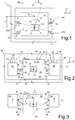
- For a better understanding of the present invention, preferred embodiments thereof are now described, purely by way of non-limiting example, with reference to the attached drawings, wherein:
-
Figure 1 is a schematic view of a known accelerometer, for detecting in-plane accelerations; -
Figure 2 is a schematic top plan view of an embodiment of the present accelerometer, for detecting in-plane accelerations, in a first operating position; -
Figure 3 is a schematic top plan view of the accelerometer ofFigure 2 , in a second operating position; -
Figure 4 is a schematic top plan view of the accelerometer ofFigure 2 , in a different operating position; -
Figure 5 is a representation in the frequency domain of signals obtainable with the accelerometer ofFigures 2-4 ; -
Figure 6 is a flowchart of a possible processing of the signal supplied by the present accelerometer, in case of discrete-time detection; -
Figure 7 shows a block diagram of a possible processing of the signal supplied by the present accelerometer, in case of continuous-time detection; -
Figure 8 shows a circuit equivalent of a component of the block diagram ofFigure 7 ; -
Figure 9 is a top plan view of a different embodiment of the present accelerometer, for detecting out-of-plane accelerations, in a first operating position; -
Figure 10 is a schematic top plan view of the accelerometer ofFigure 9 , in a second operating position; -
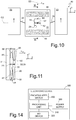
Figure 11 is a cross-section taken along section plane XI-XI ofFigure 10 ; -
Figure 12 is a top plan view of a different embodiment of the present accelerometer, for detecting in-plane accelerations; -
Figure 13 is a top plan view of another embodiment of the present accelerometer for detecting out-of-plane accelerations; and -
Figure 14 shows a block diagram of an electronic apparatus including the present accelerometer. -
Figure 2 is a schematic illustration of the structure of an embodiment of anaccelerometer 20 designed for detecting external in-plane accelerations, made in MEMS technology. In the example illustrated, theaccelerometer 20 is configured to detect accelerations directed parallel to an axis X belonging to a cartesian reference system XYZ. - In detail, the
accelerometer 20 is formed in a die of conductive material, typically of monocrystalline or polycrystalline silicon, comprising a supporting region 24 (typically fixed with respect to the die and is thus defined hereinafter also as "fixed region"), represented schematically inFigure 2 and carrying a suspendedregion 21. - The suspended
region 21 is here formed by three parts: acentral region 22 and twolateral regions 23. Thecentral region 22 and thelateral regions 23 are provided in a same semiconductor material layer, are monolithic with each other, and are suspended over a substrate (not shown) forming part of the supportingregion 24. Thelateral regions 23 are connected to thecentral region 22 through respectiveelastic connection regions 25 monolithic with thecentral region 22 and with thelateral regions 23, also suspended over the substrate (not shown). The suspendedregion 21 has a uniform thickness in direction Z, perpendicular to the drawing plane; moreover, the thickness of the suspendedregion 21 is much smaller than its dimensions in directions X and Y. - The
central region 22 is anchored to the substrate (not shown) through ananchorage 27 and elastic suspension elements, also referred to as "springs 28". - The
anchorage 27 is basically formed by a column extending perpendicularly to the drawing plane (parallel to axis Z) and terminates within anopening 29 in thecentral region 22. Theanchorage 27 is connected to the suspendedregion 21 through thesprings 28 and defines a rotation axis O1 for the suspendedregion 21. - Also the
springs 28 extend through theopening 29, here parallel to axis Y, between theanchorage 27 and two opposite points (along axis Y) of theopening 29. Thesprings 28, in a per se known manner, are shaped so as to allow rotation of the suspendedregion 21 only about the rotation axis O1, as indicated by the arrow D. - In
Figure 2 , thecentral region 22 has a rectangular shape in top plan view (in the plane XY), with a pair offirst sides 30 parallel to axis X and a pair ofsecond sides 31 parallel to axis Y. - In the
accelerometer 20 ofFigure 2 , thecentral region 22 has a symmetrical structure with respect to planes XZ, YZ passing through the rotation axis O1, the traces whereof inFigure 2 are represented by a first axis S1 (longitudinal symmetry axis at rest) and by a second axis S2 (transverse symmetry axis). Consequently, thecentral region 22 has a centroid B1 arranged along rotation axis O1. - Each
elastic connection region 25 extends from a respectivesecond side 31 of thecentral region 22, starting from median portions of these sides and extend, at rest, along first axis S1. Theelastic connection regions 25 have the same shape; in particular, they have the same dimensions in directions X and Y. -
Lateral regions 23 thus extend on the twosecond sides 31 of thecentral region 22 opposite to the second axis S2.Lateral regions 23 have the same shape and size. Here both of them have a rectangular shape and are connected to theelastic connection regions 25 so that, in the rest position ofFigure 2 , they are arranged symmetrically to both axes S1, S2. - Consequently, at rest, the centroid B1 of the entire suspended
structure 21 is the same as the centroid of the central region and lies along the rotation axis O1. - The
central region 22 carries, on thesecond sides 31,mobile sensing electrodes 35, facing corresponding fixedsensing electrodes 36. As inFigure 1 , themobile sensing electrodes 35 and fixedsensing electrodes 36 formcapacitive sensing elements 37 whose capacitive variation is used for measuring external accelerations, as discussed in greater detail hereinafter. - Furthermore, the
lateral regions 23 are each coupled to arespective driving assembly 40 designed to control displacement of thelateral regions 23 parallel to axis Y. In the illustrated example, each drivingassembly 40 comprisesmobile driving electrodes 41, which are fixed with respect to a respectivelateral region 23, and fixed drivingelectrodes 42, which are fixed with respect to the supportingregion 24. Themobile driving electrodes 41 and the fixed drivingelectrodes 42 are comb-fingered with respect to each other and extend parallel to the plane YZ. However, other driving modes are possible. - In addition, the
elastic connection regions 25 are configured to allow a displacement of thelateral regions 23 substantially parallel to axis Y with respect to thecentral region 22. - By controlling the
lateral regions 23 through therespective driving assemblies 40, it is possible to bring the suspendedstructure 21 from the rest position ofFigure 2 , where, as said, the entire suspendedstructure 21 is arranged symmetrically with respect to the first axis S1 and has a centroid B1 on the rotation axis O1 (zero-arm position), into a first modulated-arm position, visible inFigure 3 or inFigure 4 , where thelateral regions 23 are no longer in a symmetrical position with respect to the first axis S1, and thus the suspendedstructure 21 has a centroid B2 shifted with respect to the rotation axis O1 by an arm b. - Displacement of the
lateral regions 23 allows discrimination of the capacitance variation associated with thecapacitive sensing elements 37 and due to stress phenomena from the capacitance variation of the capacitive elements due to an external acceleration. - In particular, according to a sensing mode, the displacement of the
lateral regions 23 is controlled in a discrete time mode, and an external processing system, via a capacitance/voltage converter interface, reads the signals generated by thecapacitive sensing elements 37 in two distinct positions, for example, in the rest position (shown inFigure 2 ) and in a measure position (for example, in the position ofFigure 3 ). - Specifically, with a reading of the signals generated by the
capacitive sensing elements 37 in the rest position of the suspendedregion 21, since the centroidal axis coincides with the rotation axis, an external acceleration aext does not bring about any rotation of the suspendedregion 21 about the rotation axis O1, and possible rotations thereof are only due to stress and cause a first capacitive variation ΔCo1 given by
- In the measure position of
Figure 2 or 3 , instead, due to eccentricity of the centroidal axis B2 with respect to the rotation axis O1, the suspendedregion 21 turns both as a result of the external acceleration aext and as a result of the stresses. In this situation, the capacitance variation associated with thecapacitive sensing elements 37 ΔC o2 is given by
- By subtracting Eq. (5) from Eq. (6), a processing stage downstream of the
accelerometer 20 is thus able to isolate just the capacitive variation ΔCa due to the external acceleration aext and, from this, in a known manner, to obtain the value of the external acceleration aext. - Detection of the external acceleration aext may thus be made in two steps, as shown in
Figure 6 . In a first step (step 100) a first biasing voltage (for example, 0V) is applied, and,step 102, the first capacitive variation ΔC o1 is measured. In a second step (step 104), a second biasing voltage is applied, and (step 106) the second capacitive variation ΔC o2 is measured. Then, step 108, the first and second capacitive variations are subtracted from each other. - In this way, it is possible eliminate the effects of stress, which are substantially constant, irrespective of the above geometry variation of the
accelerometer 20. - Furthermore, with the described modulatable structure, it is possible to modulate the sensitivity of the sensor. In fact, for the
accelerometer 20, Eq. (1) can be rewritten as
region 21 due to the external acceleration aext, m = m0 + m1 is the sum of mass m0 of the central region and mass m1 of thelateral regions 23, xm is the modulatable arm of the suspended region, and k is the elasticity of theelastic connection regions 25. - The sensitivity is thus proportional to the arm xm, in turn, correlated to the ratio between masses m0 and m1 (which is the greater, the greater the lateral mass m1 with respect to the central mass m0) as well as to the displacement of the
lateral masses 23. To increase the sensitivity, then, the suspendedregion 21 can be designed so that m0 << m1, for example for a same total mass m as in known solution ofFigure 1 . - According to a different embodiment of the described driving method, detection of the external acceleration aext may be made by displacing the
lateral regions 23 between two positions, none of which is the rest position. - For instance, detection of the capacitance associated with the
capacitive sensing elements 37 can be made in two steps characterized by displacement of the centroid into two positions (B2, B3) arranged on opposite sides of the first axis S1, as shown inFigures 3 and4 . - In fact, in this case, reading the capacitive variation associated with the
capacitive sensing elements 37 with respect to the rest position (with no driving) in a first modulated-arm position, for example, in the position ofFigure 3 , yields the value
capacitive sensing elements 37 with respect to the rest position in a second modulated-arm position, for example, in the position ofFigure 4 , yields the value
- By subtracting Eq. (8) from Eq. (7), it is thus possible also in this case to isolate just the capacitive variation ΔCa due to the external acceleration aext.
- According to yet a different embodiment, modulation of the geometrical configuration of the suspended
region 21 may occur in continuous time mode, for example, by controlling thedriving assemblies 40 via a sinusoidal signal at the frequency fm = ωm /2π. In this way, the arm xm and thus the position of the centroid B are modified in a continuous way according to a sinusoidal behavior. - The arm xm is thus given by

- Writing the external acceleration as


- The moment exerted by the external acceleration aext is thus equivalent to the moment exerted by an equivalent external acceleration a'ext modulated at a not zero frequency for a constant arm X. The transform of the equivalent external acceleration a'ext in the frequency domain is shown in
Figure 5 and has two harmonic components (indicated by the arrows 46) at the frequencies (ωm + ωin ) and (ω m - ωin ). By appropriately choosing the modulation frequency fm = ωm /2π of the driving voltage supplied to thedriving assemblies 40, for example, equal to the resonance frequency of the suspendedmass 21, the components of the equivalent external acceleration signal may have a frequency very different from the zero frequency of the signal due to stress, represented inFigure 5 by anarrow 45, which can thus being eliminated by a simple filter. Modulation of the external acceleration indeed may also give rise to low-frequency components (not shown), which are not distinguishable from the stress signal; their elimination does not, however, create problems, since the desired information of external acceleration may be obtaining from the high-frequency components. - Demodulation of the equivalent acceleration signal may be carried out, for example, by a
processing circuit 48 arranged downstream of theaccelerometer 20, as shown inFigure 7 . - In
Figure 7 , theaccelerometer 20 is represented schematically by a block, receiving the external acceleration aext and a biasing voltage Vb generated by a drivingcircuit 85 from a modulation signal Vm and supplied to the driving assemblies 40 (Figure 2 ) for modulating the geometry of the suspendedmass 21, as explained above. As mentioned, the driving voltage Vm (as likewise the modulation signal Vm) is an ac voltage having a frequency fm = ωm/2π. - In the embodiment of
Figure 7 , theprocessing circuit 48 comprises amodulation voltage source 86, a capacitance/voltage converter block 80, a high-pass filter 81, and amixer 82. Themodulation voltage source 86, the capacitance/voltage converter 80, the high-pass filter 81, and thedemodulator 82 are provided in a different die, for example, an ASIC. - The modulation-
voltage source 86 generates the modulation voltage Vm, also supplied to thedemodulator 82. - The capacitance/
voltage converter circuit 80 is a connection interface, formed, for example, by a charge amplifier connected to thecapacitive sensing elements 37 of the accelerometer 20 (Figure 2 ). - The
mixer 82 is, for example, implemented as a pair of MOS transistors, as illustrated in the detail ofFigure 8 . - In the circuit of
Figure 7 , a capacitive variation signal sΔC generated by thecapacitive sensing elements 37, after conversion into a signal sac by the C/V converter 80, is filtered by the high-pass filter 81 and demodulated in themixer 82. The output signal V0, correlated to the external acceleration aext alone, can subsequently be processed in a known way. -
Figures 9-11 show an embodiment of anaccelerometer 50 that is designed to detect external accelerations perpendicular to the drawing planes ofFigures 9 and10 (which may be approximated with the plane of the suspended region, due to its small thickness). In the illustrated example, theaccelerometer 50 is configured to detect accelerations directed parallel to an axis Z belonging to a cartesian reference system XYZ. - The
accelerometer 50 has a structure as a whole similar to theaccelerometer 20 ofFigures 2-4 , except for the type of movement allowed to the suspended region and thus for the position of the sensing electrodes. The elements in common with theaccelerometer 20 will thus be designated by the same reference numbers and will not be described any further herein. - In detail, in the
accelerometer 50, thecentral region 22 is anchored to the substrate 51 (visible inFigure 11 ) belonging to the supportingregion 24 via theanchorage 27 and a pair ofsprings 52, which are configured to allow rotation of the suspendedmass 21 about an axis of the ideal plane defined by the suspendedmass 21. Herecentral region 22 is rotatable about arotation axis 02 parallel to axis X, and thesprings 52 are torsion springs, extending parallel to axis X. - In addition,
mobile sensing electrodes 55 are arranged on the bottom surface 56 of the central region 22 (see in particularFigure 11 ) and face respective fixedsensing electrodes 57, arranged on thesubstrate 51. Also here, themobile sensing electrodes 55 and the fixedsensing electrodes 57 form capacitive sensing elements 58 (Figure 11 ). - Also in the embodiment of
Figures 9-11 , the suspendedregion 21 has a arm b that may be modulated, and the measure may be carried out in discrete time mode (electromechanical chopping) or in continuous time mode (electromechanical modulation). - In detail, in the discrete time measure mode, the
lateral regions 23 are driven by the driving assemblies 40 (Figure 9 ) between a rest position, shown inFigure 9 , where the suspendedregion 21 has a configuration symmetrical with respect to both axes S1 and S2, and the arm b (distance between the centroid B and the rotation axis 02) is zero, and a measure position, shown inFigure 10 , where the suspendedregion 21 has a non-symmetrical configuration with respect to the first axis S1, and the arm b is thus non-zero. - In the rest position (
Figure 9 andFigure 11 with solid line), due to the symmetry of the suspendedregion 21 and the presence of a zero arm b, an external acceleration aext does not cause any rotation of the suspendedregion 21 about therotation axis 02. Any possible rotations are thus only due to stresses, which may be detected through thecapacitive sensing elements 58. - Instead, in the measure position (illustrated, for example, in
Figure 10 and inFigure 11 with a dashed line), due to the displacement of the centroidal axis B1 with respect to therotation axis 02 and the presence of a non-zero arm b, the suspendedregion 21 turns both as a result of the external acceleration aext and as a result of the stresses (see in particularFigure 11 ). - As described previously, for the detection of external in-plane accelerations, through a two-step detection, at rest and in a measure position, and acquiring the corresponding capacitive variation values, it is possible to eliminate the effect of the stresses, as discussed in detail above.
- Also in this case, as an alternative to the above, detection of the capacitive variation values may be made discrete-time in two translated positions.
- In the continuous-time measure mode, the
lateral regions 23 are driven by the driving assemblies 40 (Figure 9 ) continuously, via a sinusoidal driving signal. As described above, by filtering the obtained signal and demodulating it with theprocessing circuit 48, it is possible to obtain the value of the external acceleration aext. -
Figure 12 shows an embodiment of anaccelerometer 60 designed to detect in-plane external accelerations. In the illustrated example, theaccelerometer 60 is configured to detect external accelerations aext parallel to an axis X belonging to a cartesian reference system XYZ. - The
accelerometer 60 comprises a suspendedregion 61 symmetrical, in the rest position, both with respect to a first axis S1 parallel to axis X and with respect to a second axis S2 parallel to axis Y. - In the
accelerometer 60, the lateral regions are formed by a single frame (designated by 63), which has a quadrangular shape and surrounds acentral region 62. Theframe 63 is carried by thecentral region 62 throughelastic connection regions 65, which extend along the second axis S2. Specifically, eachelastic connection region 65, with a symmetrical configuration with respect to the second axis S2, has a pair ofU-shaped portions 66, turned over with respect to each other and facing each other so as to form, together, the perimeter of a rectangle, two sides whereof are connected, in a median position, to thecentral region 62 and, respectively, to an inner side of theframe 63 viarectilinear portions 67. In this way, theelastic connection regions 65 allow translation of theframe 63 with respect to thecentral region 62 along axis Y, as in the case of thelateral regions 23 ofFigures 2-4 and9-10 . - Driving
assemblies 68 are coupled on two outer opposite sides of theframe 63, for controlling translation of theframe 63 between a rest position and a measure position, or between two opposite measure positions, as in the case of thelateral structures 63. -
Fixed sensing electrodes 90 are here formed within the perimeter of thecentral region 62. The fixedsensing electrodes 90, formed by conductive regions, for example, of metal and carried by portions projecting from the substrate (not illustrated), extend withinopenings 64 formed in thecentral region 62 andface corresponding walls 91 of thecentral region 62. The fixedsensing electrodes 90 define mobile sensing electrodes and thus form, with thewalls 91,capacitive sensing elements 69. In this way, in eachopening 64, twocapacitive sensing elements 90 are present, designed to have opposite capacitive variations as a result of stresses and external accelerations. -
Figure 13 shows an embodiment of anaccelerometer 70 designed to detect out-of-plane external accelerations. In the illustrated example, theaccelerometer 70 is configured to detect external accelerations aext parallel to an axis Z belonging to a cartesian reference system XYZ. - The
accelerometer 70 has aframe 73 similar toFigure 13 , and thus surrounding thecentral region 72, and the latter is shaped like a rotated H. Theaccelerometer 70 further compriseselastic connection regions 75 and drivingassemblies 78 shaped like therespective elements Figure 12 . Furthermore,capacitive sensing elements 79 are likewise shaped like thecorresponding elements 58 ofFigures 9-11 . -
Figure 14 shows a block diagram of anelectronic device 300, which comprises an accelerometer, such as one ofaccelerometers device 200. The accelerometer may, for example, be used to detect vibrations, determine orientation of the electronic device, or recognise free-fall conditions. - The
electronic device 300 may be a mobile communication apparatus, such as a cellphone and a personal digital assistant, a portable computer, a desktop computer, a photo or videocamera device, a wearable device, such as a smartwatch, or any other electronic device. Theelectronic device 300 comprises aprocessing unit 310 and the encapsulateddevice 200, electrically coupled to theprocessing unit 310. Theprocessing unit 310 includes control circuitry, including, for example, one or more processors, discrete memory and logic, including theprocessing circuit 48 ofFigure 7 . Theprocessing unit 310 is configured to transmit and receive signals to/from the encapsulateddevice 200. The electronic device may further comprise an input/output device 320, for example, a keypad or a display coupled to theprocessing unit 310. Theelectronic device 300 may further comprise apower supply 330, which may be a battery or components for coupling to an external supply source. - The described accelerometer allows detection of external accelerations in a very accurate way, thanks to the possibility of eliminating the dc components that adversely affect stability and precision of measure.
- The accelerometer may be arranged in the same cavity as the gyroscopes, when the apparatus includes both these devices, thus enabling a reduction of the space.
- The described accelerometer has a high stiffness and thus a high robustness as regard stiction of the mobile electrodes against the fixed elements of the structure.
- Finally, it is clear that modifications and variations may be made to the device and method described and illustrated herein, without thereby departing from the scope of the present invention, as defined in the attached claims. For instance, the various described embodiments may be combined so as to provide further solutions.
- Furthermore, the lateral regions 23 (and the
frame 63, 73) may be mobile with a generic movement of roto-translation (including rotation) with respect to thecentral region
Claims (16)
- An integrated MEMS accelerometric sensor, comprising:a suspended region (21) mobile with respect to a supporting structure (24); anda sensing assembly (37; 58; 69; 79) coupled to the suspended region, configured to detect a movement of the suspended region with respect to the supporting structure;wherein the suspended region (21) has a variable geometry.
- The accelerometric sensor according to claim 1, wherein the suspended region (21) has a geometry variable between at least two configurations associated with respective centroids, different from each other.
- The accelerometric sensor according to claim 2, wherein the suspended region (21) comprises a first region (22; 62; 72) rotatably anchored to the supporting structure (24), and a second region (23; 63; 73) coupled to the first region (22) through elastic connection elements (25) configured to allow a relative movement of the second region (23; 63; 73) with respect to the first region (22; 62; 72); the sensor further comprising a driving assembly (40) coupled to the second region (23; 63) to control the relative movement.
- The accelerometric sensor according to claim 3, wherein the driving assembly (40) is of a capacitive type and comprises driving electrode pairs (41, 42) facing each other and causing a roto-translation movement of the second region (23) with respect to the first region (22).
- The accelerometric sensor according to claim 3 or 4, further comprising a driving source (100, 104) configured to supply the driving assembly (40) with a first driving voltage in a first sensing step and with a second driving voltage in a second sensing step; the sensor further comprising a processing circuit including:a conversion interface (102, 106), coupled to the sensing assembly (37; 58; 69; 79) and configured to generate a first position-measure signal in the first sensing step and a second position-measure signal in the second sensing step; anda subtractor (108), receiving the first and second position-measure signals and generating an acceleration signal as a difference between the first and second position-measure signals.
- The accelerometric sensor according to claim 3 or 4, further comprising a driving source (86) configured to supply an ac driving voltage to the driving assembly (37; 58; 69; 79); the sensor further comprising a processing circuit (48) including:an conversion interface (80) coupled to the sensing assembly (37; 58; 69; 79) and configured to generate an ac position-measure signal;a high-pass filter (81) coupled to an output of the interface; anda demodulator (82) coupled to an output of the high-pass filter.
- The accelerometric sensor according to claim 5 or 6, wherein the suspended region (21) and the supporting region (24) are formed in a first semiconductor material die (20) and the processing circuit (48) is formed in a second semiconductor material die.
- The accelerometric sensor according to any of claims 3-7, wherein the first and second regions (22, 23) are of semiconductor material formed in a same monolithic layer.
- The accelerometric sensor according to any of claims 2-8, wherein the sensing assembly (37; 58; 69; 79) is of a capacitive type and comprises at least two sensing electrodes (35, 36; 55, 57; 91, 90) facing each other.
- The accelerometric sensor according to any of claims 3-8, wherein the second region comprises a frame (63; 73) surrounding the first region (62; 72).
- The accelerometric sensor according to any of claims 2-10, forming an in-plane acceleration sensor (20; 60), wherein the suspended region (21; 61) is anchored to the supporting structure (24) through elastic suspension elements (28) configured to allow rotation of the suspended region (21; 61) about a rotation axis (O1) perpendicular to the suspended region.
- The accelerometric sensor according to any of claims 2-10, forming an out-of-plane acceleration sensor (50; 70), wherein the suspended region (51; 71) is anchored to the supporting structure (24) through elastic suspension elements (52) configured to allow rotation of the suspended region about a rotation axis (02) parallel to the suspended region.
- A method for detecting an external acceleration using the accelerometric sensor according to any of claims 1-12, comprising the steps of:driving a suspended region (21) mobile with respect to a supporting structure (24) so that the suspended region has at least one first geometrical configuration in a first sensing step and a second geometrical configuration in a second sensing step, the first and second geometrical configurations being different from each other;acquiring first and second position measure signals correlated to a first position of the suspended region in the first step and to a second position of the suspended region in the second step; andprocessing the first and second position-measure signals for generating an accelerometric signal independent of spurious displacements of the suspended region with respect to the supporting structure.
- The method according to claim 13, wherein the suspended region (21; 61) comprises a first region (22; 62; 72) rotatably anchored to the supporting structure (24) and a second region (23; 63; 73) coupled to the first region (22; 62; 72) through elastic connection elements (25) configured to allow a relative movement of the second region (23; 63; 73) with respect to the first region (22; 62; 73); and wherein driving a suspended region comprises applying a variable driving voltage to a driving assembly (40) coupled to the second region (23; 63; 73).
- The method according to claim 14, wherein applying a variable driving voltage comprises supplying a first driving voltage in the first step and a second driving voltage in the second step,
the method further comprising:generating an acceleration signal as a difference between the first and second position-measure signals. - The method according to claim 14, wherein applying a variable driving voltage comprises supplying an ac driving voltage, and the first and second position-measure signals are samples of an ac measure signal,
the method further comprising:filtering the ac measure signal with a high-pass filter for generating a filtered signal without dc components; anddemodulating the filtered signal.
Applications Claiming Priority (1)
| Application Number | Priority Date | Filing Date | Title |
|---|---|---|---|
| ITUA2016A002172A ITUA20162172A1 (en) | 2016-03-31 | 2016-03-31 | ACCELEROMETRIC SENSOR MADE IN MEMS TECHNOLOGY WITH HIGH ACCURACY AND REDUCED SENSITIVITY TOWARDS TEMPERATURE AND AGING |
Publications (2)
| Publication Number | Publication Date |
|---|---|
| EP3226008A1 true EP3226008A1 (en) | 2017-10-04 |
| EP3226008B1 EP3226008B1 (en) | 2018-12-05 |
Family
ID=56235944
Family Applications (1)
| Application Number | Title | Priority Date | Filing Date |
|---|---|---|---|
| EP17162576.7A Active EP3226008B1 (en) | 2016-03-31 | 2017-03-23 | Accelerometric sensor in mems technology having high accuracy and low sensitivity to temperature and ageing |
Country Status (4)
| Country | Link |
|---|---|
| US (2) | US10591505B2 (en) |
| EP (1) | EP3226008B1 (en) |
| CN (3) | CN207601108U (en) |
| IT (1) | ITUA20162172A1 (en) |
Cited By (1)
| Publication number | Priority date | Publication date | Assignee | Title |
|---|---|---|---|---|
| CN114062714A (en) * | 2020-08-07 | 2022-02-18 | 意法半导体股份有限公司 | Microelectromechanical sensor device with improved stability to stress |
Families Citing this family (9)
| Publication number | Priority date | Publication date | Assignee | Title |
|---|---|---|---|---|
| ITUA20162173A1 (en) * | 2016-03-31 | 2017-10-01 | St Microelectronics Srl | ACCELEROMETRIC MEMS SENSOR HAVING HIGH ACCURACY AND REDUCED SENSITIVITY TOWARDS TEMPERATURE AND AGING |
| ITUA20162172A1 (en) * | 2016-03-31 | 2017-10-01 | St Microelectronics Srl | ACCELEROMETRIC SENSOR MADE IN MEMS TECHNOLOGY WITH HIGH ACCURACY AND REDUCED SENSITIVITY TOWARDS TEMPERATURE AND AGING |
| IT201600098502A1 (en) * | 2016-09-30 | 2018-03-30 | St Microelectronics Srl | MEMS GYROSCOPE WITH HIGH STABILITY IN RELATION TO TEMPERATURE AND HUMIDITY CHANGES |
| CN109444465B (en) * | 2018-12-29 | 2024-09-24 | 深迪半导体(绍兴)有限公司 | Accelerometer |
| IT201900017546A1 (en) * | 2019-09-30 | 2021-03-30 | St Microelectronics Srl | WATER RESISTANT MEMS BUTTON DEVICE, INPUT DEVICE INCLUDING MEMS BUTTON DEVICE AND ELECTRONIC DEVICE |
| IT202000018670A1 (en) * | 2020-07-30 | 2022-01-30 | St Microelectronics Srl | BROADBAND MEMS ACCELEROMETER FOR DETECTING VIBRATIONS |
| IT202200003506A1 (en) * | 2022-02-24 | 2023-08-24 | St Microelectronics Srl | MICROMECHANICAL DEVICE FOR IMPROVED ACCELERATION MEASUREMENT |
| CN116045939A (en) * | 2023-02-15 | 2023-05-02 | 瑞声开泰科技(武汉)有限公司 | A kind of micromechanical gyroscope and electronic product |
| US20260036441A1 (en) * | 2023-07-13 | 2026-02-05 | Apple Inc. | In-situ capacitance detection for integrated circuits and mems sensors |
Citations (3)
| Publication number | Priority date | Publication date | Assignee | Title |
|---|---|---|---|---|
| US4599896A (en) * | 1983-02-22 | 1986-07-15 | Litton Systems, Inc. | High accuracy accelerometer |
| US7066004B1 (en) * | 2004-09-02 | 2006-06-27 | Sandia Corporation | Inertial measurement unit using rotatable MEMS sensors |
| EP1975631A2 (en) * | 2007-03-28 | 2008-10-01 | Litton Systems, Inc. | Self-calibrating accelerometer |
Family Cites Families (73)
| Publication number | Priority date | Publication date | Assignee | Title |
|---|---|---|---|---|
| CA2010437A1 (en) * | 1989-02-28 | 1990-08-31 | Winthrop H. Mcclure Iii | Electrostatic force nulling accelerometer |
| US6044705A (en) * | 1993-10-18 | 2000-04-04 | Xros, Inc. | Micromachined members coupled for relative rotation by torsion bars |
| DE4414237A1 (en) * | 1994-04-23 | 1995-10-26 | Bosch Gmbh Robert | Micromechanical vibrator of an oscillation gyrometer |
| US6584845B1 (en) * | 1999-02-10 | 2003-07-01 | California Institute Of Technology | Inertial sensor and method of use |
| US6481283B1 (en) * | 1999-04-05 | 2002-11-19 | Milli Sensor Systems & Actuators, Inc. | Coriolis oscillating gyroscopic instrument |
| JP3589182B2 (en) * | 2000-07-07 | 2004-11-17 | 株式会社村田製作所 | External force measuring device |
| DE10108198A1 (en) * | 2001-02-21 | 2002-09-12 | Bosch Gmbh Robert | Yaw rate sensor |
| US20020134154A1 (en) * | 2001-03-23 | 2002-09-26 | Hsu Ying W. | Method and apparatus for on-chip measurement of micro-gyro scale factors |
| WO2002088631A2 (en) * | 2001-05-02 | 2002-11-07 | The Regents Of The University Of California | Non-resonant four degrees-of-freedom micromachined gyroscope |
| US20030033850A1 (en) * | 2001-08-09 | 2003-02-20 | Challoner A. Dorian | Cloverleaf microgyroscope with electrostatic alignment and tuning |
| US6629460B2 (en) * | 2001-08-10 | 2003-10-07 | The Boeing Company | Isolated resonator gyroscope |
| DE10148858A1 (en) * | 2001-10-04 | 2003-04-10 | Bosch Gmbh Robert | Micro-mechanical sensor, e.g. for measurement of acceleration, has a seismic mass with measurement and self-test drive electrodes arranged perpendicularly to each other so that the effects of edge loss on self-testing are reduced |
| US6955086B2 (en) * | 2001-11-19 | 2005-10-18 | Mitsubishi Denki Kabushiki Kaisha | Acceleration sensor |
| US6823734B1 (en) * | 2002-04-26 | 2004-11-30 | California Institute Of Technology | Electrostatic spring softening in redundant degree of freedom resonators |
| DE10225714A1 (en) * | 2002-06-11 | 2004-01-08 | Eads Deutschland Gmbh | Multi-axis monolithic acceleration sensor |
| KR100470590B1 (en) * | 2002-10-12 | 2005-03-08 | 삼성전기주식회사 | Microgyroscopes with suppressed translational acceleration sensing |
| JP2005049320A (en) * | 2003-07-30 | 2005-02-24 | Microstone Corp | Acceleration sensor |
| US6843127B1 (en) * | 2003-07-30 | 2005-01-18 | Motorola, Inc. | Flexible vibratory micro-electromechanical device |
| FR2858853B1 (en) * | 2003-08-13 | 2006-01-13 | Sercel Rech Const Elect | ACCELEROMETER WITH REDUCED PARASITE VIBRATION BY IMPROVED ELECTRODE FORM |
| EP1645847B1 (en) * | 2004-10-08 | 2014-07-02 | STMicroelectronics Srl | Temperature compensated micro-electromechanical device and method of temperature compensation in a micro-electromechanical device |
| JP4353087B2 (en) * | 2004-12-01 | 2009-10-28 | 株式会社デンソー | Rotational vibration type angular velocity sensor |
| US7426861B2 (en) * | 2005-06-15 | 2008-09-23 | The Charles Stark Draper Laboratory, Inc. | Tuning fork gyroscopes, accelerometers, and other sensors with improved scale factor |
| US7617728B2 (en) * | 2006-05-17 | 2009-11-17 | Donato Cardarelli | Tuning fork gyroscope |
| JP4887034B2 (en) * | 2005-12-05 | 2012-02-29 | 日立オートモティブシステムズ株式会社 | Inertial sensor |
| EP1994363A1 (en) * | 2006-03-10 | 2008-11-26 | Contitemic Microelectronic GmbH | Micromechanical rotational speed sensor |
| EP1832841B1 (en) * | 2006-03-10 | 2015-12-30 | STMicroelectronics Srl | Microelectromechanical integrated sensor structure with rotary driving motion |
| JP5300494B2 (en) * | 2006-03-10 | 2013-09-25 | コンティネンタル・テーベス・アクチエンゲゼルシヤフト・ウント・コンパニー・オッフェネ・ハンデルスゲゼルシヤフト | Rotational speed sensor with connecting rod |
| CN100483137C (en) * | 2006-05-23 | 2009-04-29 | 北京航空航天大学 | Capacitance type micromechanical accelerometer |
| US8141424B2 (en) * | 2008-09-12 | 2012-03-27 | Invensense, Inc. | Low inertia frame for detecting coriolis acceleration |
| JP2008246604A (en) * | 2007-03-29 | 2008-10-16 | Fujitsu Ltd | Micro movable element, wafer, and wafer manufacturing method |
| DE102007017209B4 (en) * | 2007-04-05 | 2014-02-27 | Fraunhofer-Gesellschaft zur Förderung der angewandten Forschung e.V. | Micromechanical inertial sensor for measuring rotation rates |
| CN100498343C (en) * | 2007-07-12 | 2009-06-10 | 中北大学 | Electric tuning resonance differential frequency accelerator |
| US8042396B2 (en) * | 2007-09-11 | 2011-10-25 | Stmicroelectronics S.R.L. | Microelectromechanical sensor with improved mechanical decoupling of sensing and driving modes |
| CN101270988B (en) | 2008-03-14 | 2011-11-30 | 江苏英特神斯科技有限公司 | Multi-shaft inertial sensor and method for measuring multi-shaft translation and rotation acceleration |
| DE102008001863A1 (en) * | 2008-05-19 | 2009-11-26 | Robert Bosch Gmbh | Accelerometer with encompassing seismic mass |
| FR2937145B1 (en) * | 2008-10-10 | 2010-09-24 | Thales Sa | MICRO-FACTORY ACCELEROMETER |
| IT1391972B1 (en) * | 2008-11-26 | 2012-02-02 | St Microelectronics Rousset | MICROELETTROMECHANICAL GYROSCOPE WITH ROTARY DRIVE MOVEMENT AND IMPROVED ELECTRICAL CHARACTERISTICS |
| IT1391973B1 (en) * | 2008-11-26 | 2012-02-02 | St Microelectronics Rousset | MONO OR BIASSIAL MICROELECTROMECHANICAL GYROSCOPE WITH INCREASED SENSITIVITY TO THE ANGULAR SPEED DETECTION |
| IT1392741B1 (en) * | 2008-12-23 | 2012-03-16 | St Microelectronics Rousset | MICROELETTROMECHANICAL GYROSCOPE WITH IMPROVED REJECTION OF ACCELERATION DISORDERS |
| JP5206709B2 (en) * | 2009-03-18 | 2013-06-12 | 株式会社豊田中央研究所 | Device having a movable body |
| DE102009002066A1 (en) * | 2009-03-31 | 2010-10-07 | Sensordynamics Ag | Method for detecting accelerations and yaw rates and MEMS sensor |
| IT1394007B1 (en) * | 2009-05-11 | 2012-05-17 | St Microelectronics Rousset | MICROELETTROMECANICAL STRUCTURE WITH IMPROVED REJECTION OF ACCELERATION DISORDERS |
| JP4868027B2 (en) * | 2009-05-26 | 2012-02-01 | 株式会社デンソー | Acceleration angular velocity sensor |
| US8549915B2 (en) * | 2009-10-23 | 2013-10-08 | The Regents Of The University Of California | Micromachined gyroscopes with 2-DOF sense modes allowing interchangeable robust and precision operation |
| ITTO20091042A1 (en) * | 2009-12-24 | 2011-06-25 | St Microelectronics Srl | MICROELETTROMECHANICAL INTEGRATED GYROSCOPE WITH IMPROVED DRIVE STRUCTURE |
| US8539832B2 (en) * | 2010-10-25 | 2013-09-24 | Rosemount Aerospace Inc. | MEMS gyros with quadrature reducing springs |
| WO2012161690A1 (en) * | 2011-05-23 | 2012-11-29 | Senodia Technologies (Shanghai) Co., Ltd. | Mems devices sensing both rotation and acceleration |
| ITTO20110806A1 (en) * | 2011-09-12 | 2013-03-13 | St Microelectronics Srl | MICROELETTROMECANICAL DEVICE INTEGRATING A GYROSCOPE AND AN ACCELEROMETER |
| US8875578B2 (en) * | 2011-10-26 | 2014-11-04 | Silicon Laboratories Inc. | Electronic damper circuit for MEMS sensors and resonators |
| DE102011057081A1 (en) * | 2011-12-28 | 2013-07-04 | Maxim Integrated Products, Inc. | Micro rotation rate sensor and method for operating a micro yaw rate sensor |
| DE102012200132B4 (en) * | 2012-01-05 | 2025-12-24 | Robert Bosch Gmbh | Rotation rate sensor and method for operating a rotation rate sensor |
| DE102012200125B4 (en) * | 2012-01-05 | 2026-03-05 | Robert Bosch Gmbh | Sensor structure and gyroscope sensor |
| DE102012207937A1 (en) * | 2012-05-11 | 2013-11-14 | Robert Bosch Gmbh | Yaw rate sensor |
| FI125238B (en) * | 2012-06-29 | 2015-07-31 | Murata Manufacturing Co | Improved oscillating gyroscope |
| US9310202B2 (en) * | 2012-07-09 | 2016-04-12 | Freescale Semiconductor, Inc. | Angular rate sensor with quadrature error compensation |
| ITTO20120855A1 (en) * | 2012-09-28 | 2014-03-29 | Milano Politecnico | INTEGRATED STRUCTURE OF DETECTIVE DETECTION OF ACCELERATION AND ANGULAR SPEED AND RELATIVE MEMS SENSOR DEVICE |
| US9341646B2 (en) * | 2012-12-19 | 2016-05-17 | Northrop Grumman Guidance And Electronics Company, Inc. | Bias reduction in force rebalanced accelerometers |
| US9075079B2 (en) * | 2013-03-07 | 2015-07-07 | MCube Inc. | Method and structure of an integrated MEMS inertial sensor device using electrostatic quadrature-cancellation |
| US9194704B2 (en) * | 2013-03-13 | 2015-11-24 | Freescale Semiconductor, Inc. | Angular rate sensor having multiple axis sensing capability |
| ITTO20130237A1 (en) * | 2013-03-22 | 2014-09-23 | St Microelectronics Srl | HIGH SENSITIVITY MICROELECTROMECHANICAL DETECTION OF Z AXIS, IN PARTICULAR FOR A MEMS ACCELEROMETER |
| US9404747B2 (en) * | 2013-10-30 | 2016-08-02 | Stmicroelectroncs S.R.L. | Microelectromechanical gyroscope with compensation of quadrature error drift |
| CN103575932B (en) * | 2013-11-20 | 2016-03-02 | 大连理工大学 | A MEMS piezoresistive accelerometer |
| JP6248576B2 (en) * | 2013-11-25 | 2017-12-20 | セイコーエプソン株式会社 | Functional element, electronic device, and moving object |
| JP6344033B2 (en) * | 2014-04-22 | 2018-06-20 | セイコーエプソン株式会社 | Angular velocity sensor, electronic device and moving object |
| EP2963387B1 (en) * | 2014-06-30 | 2019-07-31 | STMicroelectronics Srl | Micro-electro-mechanical device with compensation of errors due to disturbance forces, such as quadrature components |
| US10502568B2 (en) * | 2015-04-29 | 2019-12-10 | General Electric Company | Inertial sensing systems and methods of manufacturing the same |
| US9689677B2 (en) * | 2015-06-19 | 2017-06-27 | Nxp Usa, Inc. | MEMS device with common mode rejection structure |
| ITUA20161498A1 (en) * | 2016-03-09 | 2017-09-09 | St Microelectronics Srl | MICROMECHANICAL DETECTION STRUCTURE OF A MEMS SENSOR DEVICE, IN PARTICULAR OF A MEMS GYRO, WITH IMPROVED DRIVE CHARACTERISTICS |
| ITUA20162160A1 (en) * | 2016-03-31 | 2017-10-01 | St Microelectronics Srl | MICROMECHANICAL STRUCTURE FOR DETECTION OF A MEMS MULTI-FACTORY GYROSCOPE, HAVING REDUCED DERIVED FROM RELATED ELECTRICAL CHARACTERISTICS |
| ITUA20162172A1 (en) * | 2016-03-31 | 2017-10-01 | St Microelectronics Srl | ACCELEROMETRIC SENSOR MADE IN MEMS TECHNOLOGY WITH HIGH ACCURACY AND REDUCED SENSITIVITY TOWARDS TEMPERATURE AND AGING |
| US20180031603A1 (en) * | 2016-07-27 | 2018-02-01 | Lumedyne Technologies Incorporated | Systems and methods for detecting inertial parameters using a vibratory accelerometer with multiple degrees of freedom |
| US10634696B2 (en) * | 2016-12-19 | 2020-04-28 | Khalifa University of Science and Technology | Multi-axis accelerometers with reduced cross-axis sensitivity |
| US10712359B2 (en) * | 2018-05-01 | 2020-07-14 | Nxp Usa, Inc. | Flexure with enhanced torsional stiffness and MEMS device incorporating same |
-
2016
- 2016-03-31 IT ITUA2016A002172A patent/ITUA20162172A1/en unknown
- 2016-09-29 US US15/280,720 patent/US10591505B2/en active Active
-
2017
- 2017-03-23 EP EP17162576.7A patent/EP3226008B1/en active Active
- 2017-03-27 CN CN201720310128.7U patent/CN207601108U/en not_active Withdrawn - After Issue
- 2017-03-27 CN CN201710190187.XA patent/CN107271721B/en active Active
- 2017-03-27 CN CN202011048545.1A patent/CN112213520B/en active Active
-
2019
- 2019-12-23 US US16/726,024 patent/US11408904B2/en active Active
Patent Citations (3)
| Publication number | Priority date | Publication date | Assignee | Title |
|---|---|---|---|---|
| US4599896A (en) * | 1983-02-22 | 1986-07-15 | Litton Systems, Inc. | High accuracy accelerometer |
| US7066004B1 (en) * | 2004-09-02 | 2006-06-27 | Sandia Corporation | Inertial measurement unit using rotatable MEMS sensors |
| EP1975631A2 (en) * | 2007-03-28 | 2008-10-01 | Litton Systems, Inc. | Self-calibrating accelerometer |
Cited By (1)
| Publication number | Priority date | Publication date | Assignee | Title |
|---|---|---|---|---|
| CN114062714A (en) * | 2020-08-07 | 2022-02-18 | 意法半导体股份有限公司 | Microelectromechanical sensor device with improved stability to stress |
Also Published As
| Publication number | Publication date |
|---|---|
| US20170285061A1 (en) | 2017-10-05 |
| US11408904B2 (en) | 2022-08-09 |
| US20200132711A1 (en) | 2020-04-30 |
| CN207601108U (en) | 2018-07-10 |
| CN112213520B (en) | 2022-12-27 |
| CN107271721A (en) | 2017-10-20 |
| CN107271721B (en) | 2020-10-27 |
| US10591505B2 (en) | 2020-03-17 |
| CN112213520A (en) | 2021-01-12 |
| EP3226008B1 (en) | 2018-12-05 |
| ITUA20162172A1 (en) | 2017-10-01 |
Similar Documents
| Publication | Publication Date | Title |
|---|---|---|
| US11408904B2 (en) | Accelerometric sensor in mems technology having high accuracy and low sensitivity to temperature and ageing | |
| US9278847B2 (en) | Microelectromechanical gyroscope with enhanced rejection of acceleration noises | |
| TWI507347B (en) | Micromechanical sensor element | |
| US9696158B2 (en) | Gyro sensor and composite sensor comprising gyro sensor | |
| CN105556242B (en) | Gyroscope structure and gyroscope with improved quadrature compensation | |
| TWI616656B (en) | A mems sensor and a semiconductor package | |
| EP3598146B1 (en) | Microelectromechanical device for out-of-plane motion detection | |
| WO2013030798A1 (en) | I improved detection structure for a z-axis resonant accelerometer | |
| US20140283605A1 (en) | High-sensitivity, z-axis micro-electro-mechanical detection structure, in particular for an mems accelerometer | |
| EP3401688B1 (en) | Capacitive microelectromechanical accelerometer | |
| CN103292799B (en) | Electric measuring method for vibrating amplitude of silicon micro-electromechanical structure | |
| US11835541B2 (en) | MEMS accelerometric sensor having high accuracy and low sensitivity to temperature and aging | |
| CN101855515A (en) | Rotational speed sensor with two sensor shafts | |
| US20170343350A1 (en) | Angular rate sensor | |
| Xiao et al. | A temperature self-calibrating torsional accelerometer with fully differential configuration and integrated reference capacitor | |
| Tocchio et al. | Electro-mechanical chopping & modulation of acceleration: The geometry-modulated accelerometer | |
| Lee et al. | A Non Vacuum Packaged Silicon Micro Gyroscope | |
| CN116643063A (en) | Micromechanical Devices for Enhanced Acceleration Measurements |
Legal Events
| Date | Code | Title | Description |
|---|---|---|---|
| PUAI | Public reference made under article 153(3) epc to a published international application that has entered the european phase |
Free format text: ORIGINAL CODE: 0009012 |
|
| STAA | Information on the status of an ep patent application or granted ep patent |
Free format text: STATUS: THE APPLICATION HAS BEEN PUBLISHED |
|
| AK | Designated contracting states |
Kind code of ref document: A1 Designated state(s): AL AT BE BG CH CY CZ DE DK EE ES FI FR GB GR HR HU IE IS IT LI LT LU LV MC MK MT NL NO PL PT RO RS SE SI SK SM TR |
|
| AX | Request for extension of the european patent |
Extension state: BA ME |
|
| STAA | Information on the status of an ep patent application or granted ep patent |
Free format text: STATUS: REQUEST FOR EXAMINATION WAS MADE |
|
| 17P | Request for examination filed |
Effective date: 20180403 |
|
| RBV | Designated contracting states (corrected) |
Designated state(s): AL AT BE BG CH CY CZ DE DK EE ES FI FR GB GR HR HU IE IS IT LI LT LU LV MC MK MT NL NO PL PT RO RS SE SI SK SM TR |
|
| GRAP | Despatch of communication of intention to grant a patent |
Free format text: ORIGINAL CODE: EPIDOSNIGR1 |
|
| STAA | Information on the status of an ep patent application or granted ep patent |
Free format text: STATUS: GRANT OF PATENT IS INTENDED |
|
| INTG | Intention to grant announced |
Effective date: 20180528 |
|
| GRAJ | Information related to disapproval of communication of intention to grant by the applicant or resumption of examination proceedings by the epo deleted |
Free format text: ORIGINAL CODE: EPIDOSDIGR1 |
|
| STAA | Information on the status of an ep patent application or granted ep patent |
Free format text: STATUS: REQUEST FOR EXAMINATION WAS MADE |
|
| GRAR | Information related to intention to grant a patent recorded |
Free format text: ORIGINAL CODE: EPIDOSNIGR71 |
|
| GRAS | Grant fee paid |
Free format text: ORIGINAL CODE: EPIDOSNIGR3 |
|
| STAA | Information on the status of an ep patent application or granted ep patent |
Free format text: STATUS: GRANT OF PATENT IS INTENDED |
|
| GRAA | (expected) grant |
Free format text: ORIGINAL CODE: 0009210 |
|
| STAA | Information on the status of an ep patent application or granted ep patent |
Free format text: STATUS: THE PATENT HAS BEEN GRANTED |
|
| INTC | Intention to grant announced (deleted) | ||
| AK | Designated contracting states |
Kind code of ref document: B1 Designated state(s): AL AT BE BG CH CY CZ DE DK EE ES FI FR GB GR HR HU IE IS IT LI LT LU LV MC MK MT NL NO PL PT RO RS SE SI SK SM TR |
|
| INTG | Intention to grant announced |
Effective date: 20181023 |
|
| REG | Reference to a national code |
Ref country code: GB Ref legal event code: FG4D |
|
| REG | Reference to a national code |
Ref country code: CH Ref legal event code: EP |
|
| REG | Reference to a national code |
Ref country code: AT Ref legal event code: REF Ref document number: 1073731 Country of ref document: AT Kind code of ref document: T Effective date: 20181215 |
|
| REG | Reference to a national code |
Ref country code: IE Ref legal event code: FG4D |
|
| REG | Reference to a national code |
Ref country code: DE Ref legal event code: R096 Ref document number: 602017001156 Country of ref document: DE |
|
| REG | Reference to a national code |
Ref country code: NL Ref legal event code: MP Effective date: 20181205 |
|
| REG | Reference to a national code |
Ref country code: AT Ref legal event code: MK05 Ref document number: 1073731 Country of ref document: AT Kind code of ref document: T Effective date: 20181205 |
|
| REG | Reference to a national code |
Ref country code: LT Ref legal event code: MG4D |
|
| PG25 | Lapsed in a contracting state [announced via postgrant information from national office to epo] |
Ref country code: LV Free format text: LAPSE BECAUSE OF FAILURE TO SUBMIT A TRANSLATION OF THE DESCRIPTION OR TO PAY THE FEE WITHIN THE PRESCRIBED TIME-LIMIT Effective date: 20181205 Ref country code: HR Free format text: LAPSE BECAUSE OF FAILURE TO SUBMIT A TRANSLATION OF THE DESCRIPTION OR TO PAY THE FEE WITHIN THE PRESCRIBED TIME-LIMIT Effective date: 20181205 Ref country code: AT Free format text: LAPSE BECAUSE OF FAILURE TO SUBMIT A TRANSLATION OF THE DESCRIPTION OR TO PAY THE FEE WITHIN THE PRESCRIBED TIME-LIMIT Effective date: 20181205 Ref country code: BG Free format text: LAPSE BECAUSE OF FAILURE TO SUBMIT A TRANSLATION OF THE DESCRIPTION OR TO PAY THE FEE WITHIN THE PRESCRIBED TIME-LIMIT Effective date: 20190305 Ref country code: NO Free format text: LAPSE BECAUSE OF FAILURE TO SUBMIT A TRANSLATION OF THE DESCRIPTION OR TO PAY THE FEE WITHIN THE PRESCRIBED TIME-LIMIT Effective date: 20190305 Ref country code: LT Free format text: LAPSE BECAUSE OF FAILURE TO SUBMIT A TRANSLATION OF THE DESCRIPTION OR TO PAY THE FEE WITHIN THE PRESCRIBED TIME-LIMIT Effective date: 20181205 Ref country code: ES Free format text: LAPSE BECAUSE OF FAILURE TO SUBMIT A TRANSLATION OF THE DESCRIPTION OR TO PAY THE FEE WITHIN THE PRESCRIBED TIME-LIMIT Effective date: 20181205 Ref country code: FI Free format text: LAPSE BECAUSE OF FAILURE TO SUBMIT A TRANSLATION OF THE DESCRIPTION OR TO PAY THE FEE WITHIN THE PRESCRIBED TIME-LIMIT Effective date: 20181205 |
|
| PG25 | Lapsed in a contracting state [announced via postgrant information from national office to epo] |
Ref country code: GR Free format text: LAPSE BECAUSE OF FAILURE TO SUBMIT A TRANSLATION OF THE DESCRIPTION OR TO PAY THE FEE WITHIN THE PRESCRIBED TIME-LIMIT Effective date: 20190306 Ref country code: RS Free format text: LAPSE BECAUSE OF FAILURE TO SUBMIT A TRANSLATION OF THE DESCRIPTION OR TO PAY THE FEE WITHIN THE PRESCRIBED TIME-LIMIT Effective date: 20181205 Ref country code: SE Free format text: LAPSE BECAUSE OF FAILURE TO SUBMIT A TRANSLATION OF THE DESCRIPTION OR TO PAY THE FEE WITHIN THE PRESCRIBED TIME-LIMIT Effective date: 20181205 Ref country code: AL Free format text: LAPSE BECAUSE OF FAILURE TO SUBMIT A TRANSLATION OF THE DESCRIPTION OR TO PAY THE FEE WITHIN THE PRESCRIBED TIME-LIMIT Effective date: 20181205 |
|
| PG25 | Lapsed in a contracting state [announced via postgrant information from national office to epo] |
Ref country code: NL Free format text: LAPSE BECAUSE OF FAILURE TO SUBMIT A TRANSLATION OF THE DESCRIPTION OR TO PAY THE FEE WITHIN THE PRESCRIBED TIME-LIMIT Effective date: 20181205 |
|
| PG25 | Lapsed in a contracting state [announced via postgrant information from national office to epo] |
Ref country code: PL Free format text: LAPSE BECAUSE OF FAILURE TO SUBMIT A TRANSLATION OF THE DESCRIPTION OR TO PAY THE FEE WITHIN THE PRESCRIBED TIME-LIMIT Effective date: 20181205 Ref country code: IT Free format text: LAPSE BECAUSE OF FAILURE TO SUBMIT A TRANSLATION OF THE DESCRIPTION OR TO PAY THE FEE WITHIN THE PRESCRIBED TIME-LIMIT Effective date: 20181205 Ref country code: CZ Free format text: LAPSE BECAUSE OF FAILURE TO SUBMIT A TRANSLATION OF THE DESCRIPTION OR TO PAY THE FEE WITHIN THE PRESCRIBED TIME-LIMIT Effective date: 20181205 Ref country code: PT Free format text: LAPSE BECAUSE OF FAILURE TO SUBMIT A TRANSLATION OF THE DESCRIPTION OR TO PAY THE FEE WITHIN THE PRESCRIBED TIME-LIMIT Effective date: 20190405 |
|
| PG25 | Lapsed in a contracting state [announced via postgrant information from national office to epo] |
Ref country code: IS Free format text: LAPSE BECAUSE OF FAILURE TO SUBMIT A TRANSLATION OF THE DESCRIPTION OR TO PAY THE FEE WITHIN THE PRESCRIBED TIME-LIMIT Effective date: 20190405 Ref country code: RO Free format text: LAPSE BECAUSE OF FAILURE TO SUBMIT A TRANSLATION OF THE DESCRIPTION OR TO PAY THE FEE WITHIN THE PRESCRIBED TIME-LIMIT Effective date: 20181205 Ref country code: SM Free format text: LAPSE BECAUSE OF FAILURE TO SUBMIT A TRANSLATION OF THE DESCRIPTION OR TO PAY THE FEE WITHIN THE PRESCRIBED TIME-LIMIT Effective date: 20181205 Ref country code: EE Free format text: LAPSE BECAUSE OF FAILURE TO SUBMIT A TRANSLATION OF THE DESCRIPTION OR TO PAY THE FEE WITHIN THE PRESCRIBED TIME-LIMIT Effective date: 20181205 Ref country code: SK Free format text: LAPSE BECAUSE OF FAILURE TO SUBMIT A TRANSLATION OF THE DESCRIPTION OR TO PAY THE FEE WITHIN THE PRESCRIBED TIME-LIMIT Effective date: 20181205 |
|
| REG | Reference to a national code |
Ref country code: DE Ref legal event code: R097 Ref document number: 602017001156 Country of ref document: DE |
|
| PLBE | No opposition filed within time limit |
Free format text: ORIGINAL CODE: 0009261 |
|
| STAA | Information on the status of an ep patent application or granted ep patent |
Free format text: STATUS: NO OPPOSITION FILED WITHIN TIME LIMIT |
|
| PG25 | Lapsed in a contracting state [announced via postgrant information from national office to epo] |
Ref country code: SI Free format text: LAPSE BECAUSE OF FAILURE TO SUBMIT A TRANSLATION OF THE DESCRIPTION OR TO PAY THE FEE WITHIN THE PRESCRIBED TIME-LIMIT Effective date: 20181205 Ref country code: DK Free format text: LAPSE BECAUSE OF FAILURE TO SUBMIT A TRANSLATION OF THE DESCRIPTION OR TO PAY THE FEE WITHIN THE PRESCRIBED TIME-LIMIT Effective date: 20181205 Ref country code: MC Free format text: LAPSE BECAUSE OF FAILURE TO SUBMIT A TRANSLATION OF THE DESCRIPTION OR TO PAY THE FEE WITHIN THE PRESCRIBED TIME-LIMIT Effective date: 20181205 |
|
| 26N | No opposition filed |
Effective date: 20190906 |
|
| PG25 | Lapsed in a contracting state [announced via postgrant information from national office to epo] |
Ref country code: LU Free format text: LAPSE BECAUSE OF NON-PAYMENT OF DUE FEES Effective date: 20190323 |
|
| REG | Reference to a national code |
Ref country code: BE Ref legal event code: MM Effective date: 20190331 |
|
| PG25 | Lapsed in a contracting state [announced via postgrant information from national office to epo] |
Ref country code: IE Free format text: LAPSE BECAUSE OF NON-PAYMENT OF DUE FEES Effective date: 20190323 |
|
| PG25 | Lapsed in a contracting state [announced via postgrant information from national office to epo] |
Ref country code: BE Free format text: LAPSE BECAUSE OF NON-PAYMENT OF DUE FEES Effective date: 20190331 Ref country code: FR Free format text: LAPSE BECAUSE OF NON-PAYMENT OF DUE FEES Effective date: 20190331 |
|
| PG25 | Lapsed in a contracting state [announced via postgrant information from national office to epo] |
Ref country code: TR Free format text: LAPSE BECAUSE OF FAILURE TO SUBMIT A TRANSLATION OF THE DESCRIPTION OR TO PAY THE FEE WITHIN THE PRESCRIBED TIME-LIMIT Effective date: 20181205 |
|
| PG25 | Lapsed in a contracting state [announced via postgrant information from national office to epo] |
Ref country code: MT Free format text: LAPSE BECAUSE OF NON-PAYMENT OF DUE FEES Effective date: 20190323 |
|
| REG | Reference to a national code |
Ref country code: CH Ref legal event code: PL |
|
| PG25 | Lapsed in a contracting state [announced via postgrant information from national office to epo] |
Ref country code: CH Free format text: LAPSE BECAUSE OF NON-PAYMENT OF DUE FEES Effective date: 20200331 Ref country code: LI Free format text: LAPSE BECAUSE OF NON-PAYMENT OF DUE FEES Effective date: 20200331 |
|
| PG25 | Lapsed in a contracting state [announced via postgrant information from national office to epo] |
Ref country code: CY Free format text: LAPSE BECAUSE OF FAILURE TO SUBMIT A TRANSLATION OF THE DESCRIPTION OR TO PAY THE FEE WITHIN THE PRESCRIBED TIME-LIMIT Effective date: 20181205 |
|
| PG25 | Lapsed in a contracting state [announced via postgrant information from national office to epo] |
Ref country code: HU Free format text: LAPSE BECAUSE OF FAILURE TO SUBMIT A TRANSLATION OF THE DESCRIPTION OR TO PAY THE FEE WITHIN THE PRESCRIBED TIME-LIMIT; INVALID AB INITIO Effective date: 20170323 |
|
| GBPC | Gb: european patent ceased through non-payment of renewal fee |
Effective date: 20210323 |
|
| PG25 | Lapsed in a contracting state [announced via postgrant information from national office to epo] |
Ref country code: GB Free format text: LAPSE BECAUSE OF NON-PAYMENT OF DUE FEES Effective date: 20210323 |
|
| PG25 | Lapsed in a contracting state [announced via postgrant information from national office to epo] |
Ref country code: MK Free format text: LAPSE BECAUSE OF FAILURE TO SUBMIT A TRANSLATION OF THE DESCRIPTION OR TO PAY THE FEE WITHIN THE PRESCRIBED TIME-LIMIT Effective date: 20181205 |
|
| PGFP | Annual fee paid to national office [announced via postgrant information from national office to epo] |
Ref country code: DE Payment date: 20260219 Year of fee payment: 10 |