EP3225940A1 - Gas recovery system for compressor, compressor system, and refrigeration cycle system - Google Patents
Gas recovery system for compressor, compressor system, and refrigeration cycle system Download PDFInfo
- Publication number
- EP3225940A1 EP3225940A1 EP15872314.8A EP15872314A EP3225940A1 EP 3225940 A1 EP3225940 A1 EP 3225940A1 EP 15872314 A EP15872314 A EP 15872314A EP 3225940 A1 EP3225940 A1 EP 3225940A1
- Authority
- EP
- European Patent Office
- Prior art keywords
- gas
- distillation column
- supply
- line
- compressor
- Prior art date
- Legal status (The legal status is an assumption and is not a legal conclusion. Google has not performed a legal analysis and makes no representation as to the accuracy of the status listed.)
- Granted
Links
Images




Classifications
-
- F—MECHANICAL ENGINEERING; LIGHTING; HEATING; WEAPONS; BLASTING
- F25—REFRIGERATION OR COOLING; COMBINED HEATING AND REFRIGERATION SYSTEMS; HEAT PUMP SYSTEMS; MANUFACTURE OR STORAGE OF ICE; LIQUEFACTION SOLIDIFICATION OF GASES
- F25B—REFRIGERATION MACHINES, PLANTS OR SYSTEMS; COMBINED HEATING AND REFRIGERATION SYSTEMS; HEAT PUMP SYSTEMS
- F25B43/00—Arrangements for separating or purifying gases or liquids; Arrangements for vaporising the residuum of liquid refrigerant, e.g. by heat
- F25B43/02—Arrangements for separating or purifying gases or liquids; Arrangements for vaporising the residuum of liquid refrigerant, e.g. by heat for separating lubricants from the refrigerant
-
- F—MECHANICAL ENGINEERING; LIGHTING; HEATING; WEAPONS; BLASTING
- F04—POSITIVE - DISPLACEMENT MACHINES FOR LIQUIDS; PUMPS FOR LIQUIDS OR ELASTIC FLUIDS
- F04D—NON-POSITIVE-DISPLACEMENT PUMPS
- F04D29/00—Details, component parts, or accessories
- F04D29/08—Sealings
- F04D29/10—Shaft sealings
- F04D29/12—Shaft sealings using sealing-rings
- F04D29/122—Shaft sealings using sealing-rings especially adapted for elastic fluid pumps
- F04D29/124—Shaft sealings using sealing-rings especially adapted for elastic fluid pumps with special means for adducting cooling or sealing fluid
-
- F—MECHANICAL ENGINEERING; LIGHTING; HEATING; WEAPONS; BLASTING
- F04—POSITIVE - DISPLACEMENT MACHINES FOR LIQUIDS; PUMPS FOR LIQUIDS OR ELASTIC FLUIDS
- F04D—NON-POSITIVE-DISPLACEMENT PUMPS
- F04D29/00—Details, component parts, or accessories
- F04D29/08—Sealings
- F04D29/10—Shaft sealings
-
- F—MECHANICAL ENGINEERING; LIGHTING; HEATING; WEAPONS; BLASTING
- F25—REFRIGERATION OR COOLING; COMBINED HEATING AND REFRIGERATION SYSTEMS; HEAT PUMP SYSTEMS; MANUFACTURE OR STORAGE OF ICE; LIQUEFACTION SOLIDIFICATION OF GASES
- F25B—REFRIGERATION MACHINES, PLANTS OR SYSTEMS; COMBINED HEATING AND REFRIGERATION SYSTEMS; HEAT PUMP SYSTEMS
- F25B31/00—Compressor arrangements
- F25B31/002—Lubrication
- F25B31/004—Lubrication oil recirculating arrangements
-
- F—MECHANICAL ENGINEERING; LIGHTING; HEATING; WEAPONS; BLASTING
- F25—REFRIGERATION OR COOLING; COMBINED HEATING AND REFRIGERATION SYSTEMS; HEAT PUMP SYSTEMS; MANUFACTURE OR STORAGE OF ICE; LIQUEFACTION SOLIDIFICATION OF GASES
- F25B—REFRIGERATION MACHINES, PLANTS OR SYSTEMS; COMBINED HEATING AND REFRIGERATION SYSTEMS; HEAT PUMP SYSTEMS
- F25B43/00—Arrangements for separating or purifying gases or liquids; Arrangements for vaporising the residuum of liquid refrigerant, e.g. by heat
- F25B43/04—Arrangements for separating or purifying gases or liquids; Arrangements for vaporising the residuum of liquid refrigerant, e.g. by heat for withdrawing non-condensible gases
- F25B43/043—Arrangements for separating or purifying gases or liquids; Arrangements for vaporising the residuum of liquid refrigerant, e.g. by heat for withdrawing non-condensible gases for compression type systems
-
- F—MECHANICAL ENGINEERING; LIGHTING; HEATING; WEAPONS; BLASTING
- F25—REFRIGERATION OR COOLING; COMBINED HEATING AND REFRIGERATION SYSTEMS; HEAT PUMP SYSTEMS; MANUFACTURE OR STORAGE OF ICE; LIQUEFACTION SOLIDIFICATION OF GASES
- F25J—LIQUEFACTION, SOLIDIFICATION OR SEPARATION OF GASES OR GASEOUS OR LIQUEFIED GASEOUS MIXTURES BY PRESSURE AND COLD TREATMENT OR BY BRINGING THEM INTO THE SUPERCRITICAL STATE
- F25J1/00—Processes or apparatus for liquefying or solidifying gases or gaseous mixtures
- F25J1/02—Processes or apparatus for liquefying or solidifying gases or gaseous mixtures requiring the use of refrigeration, e.g. of helium or hydrogen ; Details and kind of the refrigeration system used; Integration with other units or processes; Controlling aspects of the process
- F25J1/0243—Start-up or control of the process; Details of the apparatus used; Details of the refrigerant compression system used
- F25J1/0244—Operation; Control and regulation; Instrumentation
- F25J1/0245—Different modes, i.e. 'runs', of operation; Process control
- F25J1/0249—Controlling refrigerant inventory, i.e. composition or quantity
- F25J1/025—Details related to the refrigerant production or treatment, e.g. make-up supply from feed gas itself
-
- F—MECHANICAL ENGINEERING; LIGHTING; HEATING; WEAPONS; BLASTING
- F25—REFRIGERATION OR COOLING; COMBINED HEATING AND REFRIGERATION SYSTEMS; HEAT PUMP SYSTEMS; MANUFACTURE OR STORAGE OF ICE; LIQUEFACTION SOLIDIFICATION OF GASES
- F25J—LIQUEFACTION, SOLIDIFICATION OR SEPARATION OF GASES OR GASEOUS OR LIQUEFIED GASEOUS MIXTURES BY PRESSURE AND COLD TREATMENT OR BY BRINGING THEM INTO THE SUPERCRITICAL STATE
- F25J1/00—Processes or apparatus for liquefying or solidifying gases or gaseous mixtures
- F25J1/02—Processes or apparatus for liquefying or solidifying gases or gaseous mixtures requiring the use of refrigeration, e.g. of helium or hydrogen ; Details and kind of the refrigeration system used; Integration with other units or processes; Controlling aspects of the process
- F25J1/0243—Start-up or control of the process; Details of the apparatus used; Details of the refrigerant compression system used
- F25J1/0279—Compression of refrigerant or internal recycle fluid, e.g. kind of compressor, accumulator, suction drum etc.
-
- F—MECHANICAL ENGINEERING; LIGHTING; HEATING; WEAPONS; BLASTING
- F25—REFRIGERATION OR COOLING; COMBINED HEATING AND REFRIGERATION SYSTEMS; HEAT PUMP SYSTEMS; MANUFACTURE OR STORAGE OF ICE; LIQUEFACTION SOLIDIFICATION OF GASES
- F25J—LIQUEFACTION, SOLIDIFICATION OR SEPARATION OF GASES OR GASEOUS OR LIQUEFIED GASEOUS MIXTURES BY PRESSURE AND COLD TREATMENT OR BY BRINGING THEM INTO THE SUPERCRITICAL STATE
- F25J3/00—Processes or apparatus for separating the constituents of gaseous or liquefied gaseous mixtures involving the use of liquefaction or solidification
- F25J3/02—Processes or apparatus for separating the constituents of gaseous or liquefied gaseous mixtures involving the use of liquefaction or solidification by rectification, i.e. by continuous interchange of heat and material between a vapour stream and a liquid stream
- F25J3/0204—Processes or apparatus for separating the constituents of gaseous or liquefied gaseous mixtures involving the use of liquefaction or solidification by rectification, i.e. by continuous interchange of heat and material between a vapour stream and a liquid stream characterised by the feed stream
- F25J3/0219—Refinery gas, cracking gas, coke oven gas, gaseous mixtures containing aliphatic unsaturated CnHm or gaseous mixtures of undefined nature
-
- F—MECHANICAL ENGINEERING; LIGHTING; HEATING; WEAPONS; BLASTING
- F25—REFRIGERATION OR COOLING; COMBINED HEATING AND REFRIGERATION SYSTEMS; HEAT PUMP SYSTEMS; MANUFACTURE OR STORAGE OF ICE; LIQUEFACTION SOLIDIFICATION OF GASES
- F25J—LIQUEFACTION, SOLIDIFICATION OR SEPARATION OF GASES OR GASEOUS OR LIQUEFIED GASEOUS MIXTURES BY PRESSURE AND COLD TREATMENT OR BY BRINGING THEM INTO THE SUPERCRITICAL STATE
- F25J3/00—Processes or apparatus for separating the constituents of gaseous or liquefied gaseous mixtures involving the use of liquefaction or solidification
- F25J3/02—Processes or apparatus for separating the constituents of gaseous or liquefied gaseous mixtures involving the use of liquefaction or solidification by rectification, i.e. by continuous interchange of heat and material between a vapour stream and a liquid stream
- F25J3/0228—Processes or apparatus for separating the constituents of gaseous or liquefied gaseous mixtures involving the use of liquefaction or solidification by rectification, i.e. by continuous interchange of heat and material between a vapour stream and a liquid stream characterised by the separated product stream
- F25J3/0233—Processes or apparatus for separating the constituents of gaseous or liquefied gaseous mixtures involving the use of liquefaction or solidification by rectification, i.e. by continuous interchange of heat and material between a vapour stream and a liquid stream characterised by the separated product stream separation of CnHm with 1 carbon atom or more
-
- F—MECHANICAL ENGINEERING; LIGHTING; HEATING; WEAPONS; BLASTING
- F25—REFRIGERATION OR COOLING; COMBINED HEATING AND REFRIGERATION SYSTEMS; HEAT PUMP SYSTEMS; MANUFACTURE OR STORAGE OF ICE; LIQUEFACTION SOLIDIFICATION OF GASES
- F25J—LIQUEFACTION, SOLIDIFICATION OR SEPARATION OF GASES OR GASEOUS OR LIQUEFIED GASEOUS MIXTURES BY PRESSURE AND COLD TREATMENT OR BY BRINGING THEM INTO THE SUPERCRITICAL STATE
- F25J3/00—Processes or apparatus for separating the constituents of gaseous or liquefied gaseous mixtures involving the use of liquefaction or solidification
- F25J3/02—Processes or apparatus for separating the constituents of gaseous or liquefied gaseous mixtures involving the use of liquefaction or solidification by rectification, i.e. by continuous interchange of heat and material between a vapour stream and a liquid stream
- F25J3/0228—Processes or apparatus for separating the constituents of gaseous or liquefied gaseous mixtures involving the use of liquefaction or solidification by rectification, i.e. by continuous interchange of heat and material between a vapour stream and a liquid stream characterised by the separated product stream
- F25J3/0238—Processes or apparatus for separating the constituents of gaseous or liquefied gaseous mixtures involving the use of liquefaction or solidification by rectification, i.e. by continuous interchange of heat and material between a vapour stream and a liquid stream characterised by the separated product stream separation of CnHm with 2 carbon atoms or more
-
- F—MECHANICAL ENGINEERING; LIGHTING; HEATING; WEAPONS; BLASTING
- F25—REFRIGERATION OR COOLING; COMBINED HEATING AND REFRIGERATION SYSTEMS; HEAT PUMP SYSTEMS; MANUFACTURE OR STORAGE OF ICE; LIQUEFACTION SOLIDIFICATION OF GASES
- F25J—LIQUEFACTION, SOLIDIFICATION OR SEPARATION OF GASES OR GASEOUS OR LIQUEFIED GASEOUS MIXTURES BY PRESSURE AND COLD TREATMENT OR BY BRINGING THEM INTO THE SUPERCRITICAL STATE
- F25J3/00—Processes or apparatus for separating the constituents of gaseous or liquefied gaseous mixtures involving the use of liquefaction or solidification
- F25J3/02—Processes or apparatus for separating the constituents of gaseous or liquefied gaseous mixtures involving the use of liquefaction or solidification by rectification, i.e. by continuous interchange of heat and material between a vapour stream and a liquid stream
- F25J3/0228—Processes or apparatus for separating the constituents of gaseous or liquefied gaseous mixtures involving the use of liquefaction or solidification by rectification, i.e. by continuous interchange of heat and material between a vapour stream and a liquid stream characterised by the separated product stream
- F25J3/0242—Processes or apparatus for separating the constituents of gaseous or liquefied gaseous mixtures involving the use of liquefaction or solidification by rectification, i.e. by continuous interchange of heat and material between a vapour stream and a liquid stream characterised by the separated product stream separation of CnHm with 3 carbon atoms or more
-
- F—MECHANICAL ENGINEERING; LIGHTING; HEATING; WEAPONS; BLASTING
- F25—REFRIGERATION OR COOLING; COMBINED HEATING AND REFRIGERATION SYSTEMS; HEAT PUMP SYSTEMS; MANUFACTURE OR STORAGE OF ICE; LIQUEFACTION SOLIDIFICATION OF GASES
- F25J—LIQUEFACTION, SOLIDIFICATION OR SEPARATION OF GASES OR GASEOUS OR LIQUEFIED GASEOUS MIXTURES BY PRESSURE AND COLD TREATMENT OR BY BRINGING THEM INTO THE SUPERCRITICAL STATE
- F25J3/00—Processes or apparatus for separating the constituents of gaseous or liquefied gaseous mixtures involving the use of liquefaction or solidification
- F25J3/02—Processes or apparatus for separating the constituents of gaseous or liquefied gaseous mixtures involving the use of liquefaction or solidification by rectification, i.e. by continuous interchange of heat and material between a vapour stream and a liquid stream
- F25J3/0228—Processes or apparatus for separating the constituents of gaseous or liquefied gaseous mixtures involving the use of liquefaction or solidification by rectification, i.e. by continuous interchange of heat and material between a vapour stream and a liquid stream characterised by the separated product stream
- F25J3/0247—Processes or apparatus for separating the constituents of gaseous or liquefied gaseous mixtures involving the use of liquefaction or solidification by rectification, i.e. by continuous interchange of heat and material between a vapour stream and a liquid stream characterised by the separated product stream separation of CnHm with 4 carbon atoms or more
-
- F—MECHANICAL ENGINEERING; LIGHTING; HEATING; WEAPONS; BLASTING
- F25—REFRIGERATION OR COOLING; COMBINED HEATING AND REFRIGERATION SYSTEMS; HEAT PUMP SYSTEMS; MANUFACTURE OR STORAGE OF ICE; LIQUEFACTION SOLIDIFICATION OF GASES
- F25J—LIQUEFACTION, SOLIDIFICATION OR SEPARATION OF GASES OR GASEOUS OR LIQUEFIED GASEOUS MIXTURES BY PRESSURE AND COLD TREATMENT OR BY BRINGING THEM INTO THE SUPERCRITICAL STATE
- F25J3/00—Processes or apparatus for separating the constituents of gaseous or liquefied gaseous mixtures involving the use of liquefaction or solidification
- F25J3/02—Processes or apparatus for separating the constituents of gaseous or liquefied gaseous mixtures involving the use of liquefaction or solidification by rectification, i.e. by continuous interchange of heat and material between a vapour stream and a liquid stream
- F25J3/0228—Processes or apparatus for separating the constituents of gaseous or liquefied gaseous mixtures involving the use of liquefaction or solidification by rectification, i.e. by continuous interchange of heat and material between a vapour stream and a liquid stream characterised by the separated product stream
- F25J3/0257—Processes or apparatus for separating the constituents of gaseous or liquefied gaseous mixtures involving the use of liquefaction or solidification by rectification, i.e. by continuous interchange of heat and material between a vapour stream and a liquid stream characterised by the separated product stream separation of nitrogen
-
- F—MECHANICAL ENGINEERING; LIGHTING; HEATING; WEAPONS; BLASTING
- F25—REFRIGERATION OR COOLING; COMBINED HEATING AND REFRIGERATION SYSTEMS; HEAT PUMP SYSTEMS; MANUFACTURE OR STORAGE OF ICE; LIQUEFACTION SOLIDIFICATION OF GASES
- F25J—LIQUEFACTION, SOLIDIFICATION OR SEPARATION OF GASES OR GASEOUS OR LIQUEFIED GASEOUS MIXTURES BY PRESSURE AND COLD TREATMENT OR BY BRINGING THEM INTO THE SUPERCRITICAL STATE
- F25J3/00—Processes or apparatus for separating the constituents of gaseous or liquefied gaseous mixtures involving the use of liquefaction or solidification
- F25J3/02—Processes or apparatus for separating the constituents of gaseous or liquefied gaseous mixtures involving the use of liquefaction or solidification by rectification, i.e. by continuous interchange of heat and material between a vapour stream and a liquid stream
- F25J3/0228—Processes or apparatus for separating the constituents of gaseous or liquefied gaseous mixtures involving the use of liquefaction or solidification by rectification, i.e. by continuous interchange of heat and material between a vapour stream and a liquid stream characterised by the separated product stream
- F25J3/0266—Processes or apparatus for separating the constituents of gaseous or liquefied gaseous mixtures involving the use of liquefaction or solidification by rectification, i.e. by continuous interchange of heat and material between a vapour stream and a liquid stream characterised by the separated product stream separation of carbon dioxide
-
- F—MECHANICAL ENGINEERING; LIGHTING; HEATING; WEAPONS; BLASTING
- F05—INDEXING SCHEMES RELATING TO ENGINES OR PUMPS IN VARIOUS SUBCLASSES OF CLASSES F01-F04
- F05D—INDEXING SCHEME FOR ASPECTS RELATING TO NON-POSITIVE-DISPLACEMENT MACHINES OR ENGINES, GAS-TURBINES OR JET-PROPULSION PLANTS
- F05D2260/00—Function
- F05D2260/60—Fluid transfer
- F05D2260/602—Drainage
- F05D2260/6022—Drainage of leakage having past a seal
-
- F—MECHANICAL ENGINEERING; LIGHTING; HEATING; WEAPONS; BLASTING
- F25—REFRIGERATION OR COOLING; COMBINED HEATING AND REFRIGERATION SYSTEMS; HEAT PUMP SYSTEMS; MANUFACTURE OR STORAGE OF ICE; LIQUEFACTION SOLIDIFICATION OF GASES
- F25B—REFRIGERATION MACHINES, PLANTS OR SYSTEMS; COMBINED HEATING AND REFRIGERATION SYSTEMS; HEAT PUMP SYSTEMS
- F25B45/00—Arrangements for charging or discharging refrigerant
-
- F—MECHANICAL ENGINEERING; LIGHTING; HEATING; WEAPONS; BLASTING
- F25—REFRIGERATION OR COOLING; COMBINED HEATING AND REFRIGERATION SYSTEMS; HEAT PUMP SYSTEMS; MANUFACTURE OR STORAGE OF ICE; LIQUEFACTION SOLIDIFICATION OF GASES
- F25J—LIQUEFACTION, SOLIDIFICATION OR SEPARATION OF GASES OR GASEOUS OR LIQUEFIED GASEOUS MIXTURES BY PRESSURE AND COLD TREATMENT OR BY BRINGING THEM INTO THE SUPERCRITICAL STATE
- F25J2200/00—Processes or apparatus using separation by rectification
- F25J2200/02—Processes or apparatus using separation by rectification in a single pressure main column system
-
- F—MECHANICAL ENGINEERING; LIGHTING; HEATING; WEAPONS; BLASTING
- F25—REFRIGERATION OR COOLING; COMBINED HEATING AND REFRIGERATION SYSTEMS; HEAT PUMP SYSTEMS; MANUFACTURE OR STORAGE OF ICE; LIQUEFACTION SOLIDIFICATION OF GASES
- F25J—LIQUEFACTION, SOLIDIFICATION OR SEPARATION OF GASES OR GASEOUS OR LIQUEFIED GASEOUS MIXTURES BY PRESSURE AND COLD TREATMENT OR BY BRINGING THEM INTO THE SUPERCRITICAL STATE
- F25J2200/00—Processes or apparatus using separation by rectification
- F25J2200/40—Features relating to the provision of boil-up in the bottom of a column
-
- F—MECHANICAL ENGINEERING; LIGHTING; HEATING; WEAPONS; BLASTING
- F25—REFRIGERATION OR COOLING; COMBINED HEATING AND REFRIGERATION SYSTEMS; HEAT PUMP SYSTEMS; MANUFACTURE OR STORAGE OF ICE; LIQUEFACTION SOLIDIFICATION OF GASES
- F25J—LIQUEFACTION, SOLIDIFICATION OR SEPARATION OF GASES OR GASEOUS OR LIQUEFIED GASEOUS MIXTURES BY PRESSURE AND COLD TREATMENT OR BY BRINGING THEM INTO THE SUPERCRITICAL STATE
- F25J2200/00—Processes or apparatus using separation by rectification
- F25J2200/76—Refluxing the column with condensed overhead gas being cycled in a quasi-closed loop refrigeration cycle
-
- F—MECHANICAL ENGINEERING; LIGHTING; HEATING; WEAPONS; BLASTING
- F25—REFRIGERATION OR COOLING; COMBINED HEATING AND REFRIGERATION SYSTEMS; HEAT PUMP SYSTEMS; MANUFACTURE OR STORAGE OF ICE; LIQUEFACTION SOLIDIFICATION OF GASES
- F25J—LIQUEFACTION, SOLIDIFICATION OR SEPARATION OF GASES OR GASEOUS OR LIQUEFIED GASEOUS MIXTURES BY PRESSURE AND COLD TREATMENT OR BY BRINGING THEM INTO THE SUPERCRITICAL STATE
- F25J2245/00—Processes or apparatus involving steps for recycling of process streams
- F25J2245/02—Recycle of a stream in general, e.g. a by-pass stream
-
- F—MECHANICAL ENGINEERING; LIGHTING; HEATING; WEAPONS; BLASTING
- F25—REFRIGERATION OR COOLING; COMBINED HEATING AND REFRIGERATION SYSTEMS; HEAT PUMP SYSTEMS; MANUFACTURE OR STORAGE OF ICE; LIQUEFACTION SOLIDIFICATION OF GASES
- F25J—LIQUEFACTION, SOLIDIFICATION OR SEPARATION OF GASES OR GASEOUS OR LIQUEFIED GASEOUS MIXTURES BY PRESSURE AND COLD TREATMENT OR BY BRINGING THEM INTO THE SUPERCRITICAL STATE
- F25J2260/00—Coupling of processes or apparatus to other units; Integrated schemes
- F25J2260/02—Integration in an installation for exchanging heat, e.g. for waste heat recovery
-
- F—MECHANICAL ENGINEERING; LIGHTING; HEATING; WEAPONS; BLASTING
- F25—REFRIGERATION OR COOLING; COMBINED HEATING AND REFRIGERATION SYSTEMS; HEAT PUMP SYSTEMS; MANUFACTURE OR STORAGE OF ICE; LIQUEFACTION SOLIDIFICATION OF GASES
- F25J—LIQUEFACTION, SOLIDIFICATION OR SEPARATION OF GASES OR GASEOUS OR LIQUEFIED GASEOUS MIXTURES BY PRESSURE AND COLD TREATMENT OR BY BRINGING THEM INTO THE SUPERCRITICAL STATE
- F25J2260/00—Coupling of processes or apparatus to other units; Integrated schemes
- F25J2260/20—Integration in an installation for liquefying or solidifying a fluid stream
-
- F—MECHANICAL ENGINEERING; LIGHTING; HEATING; WEAPONS; BLASTING
- F25—REFRIGERATION OR COOLING; COMBINED HEATING AND REFRIGERATION SYSTEMS; HEAT PUMP SYSTEMS; MANUFACTURE OR STORAGE OF ICE; LIQUEFACTION SOLIDIFICATION OF GASES
- F25J—LIQUEFACTION, SOLIDIFICATION OR SEPARATION OF GASES OR GASEOUS OR LIQUEFIED GASEOUS MIXTURES BY PRESSURE AND COLD TREATMENT OR BY BRINGING THEM INTO THE SUPERCRITICAL STATE
- F25J2270/00—Refrigeration techniques used
- F25J2270/02—Internal refrigeration with liquid vaporising loop
-
- Y—GENERAL TAGGING OF NEW TECHNOLOGICAL DEVELOPMENTS; GENERAL TAGGING OF CROSS-SECTIONAL TECHNOLOGIES SPANNING OVER SEVERAL SECTIONS OF THE IPC; TECHNICAL SUBJECTS COVERED BY FORMER USPC CROSS-REFERENCE ART COLLECTIONS [XRACs] AND DIGESTS
- Y02—TECHNOLOGIES OR APPLICATIONS FOR MITIGATION OR ADAPTATION AGAINST CLIMATE CHANGE
- Y02C—CAPTURE, STORAGE, SEQUESTRATION OR DISPOSAL OF GREENHOUSE GASES [GHG]
- Y02C20/00—Capture or disposal of greenhouse gases
- Y02C20/40—Capture or disposal of greenhouse gases of CO2
Definitions
- the mixed gas is discharged as the vent gas from the dry gas seal, it is necessary to additionally supply the process gas in a closed loop system, and the running cost of the compressor becomes high by an amount such that the process gas is added.
- the running cost of the compressor will be particularly high.
- the above problem may occur not only in a case where the separation gas is supplied to the separation seal but also in a case where the supply gas, such as the separation gas or other seal gas, is supplied to a seal portion of the compressor including the dry gas seal and the separation seal.
- liquid supply gas that exchanges heat with the mixed gas in the distillation column is heated and gasified and is recovered in a gas state by the supply gas recovery line together with the supply gas contained in the mixed gas.
- the recovered gaseous supply gas can be reused as the gas supplied to the seal portion of the compressor. Hence, the amount of the supply gas supplied from an external supply source to the compressor can also be reduced.
- the process gas may be Freon or hydrocarbon
- the supply gas may be carbon dioxide or hydrocarbon
- the gas recovery system for a compressor may further include a process gas circulation line that branches from the process gas recovery line and returns the liquid process gas, which is discharged from the distillation column, to the distillation column after being gasified.
- the heating of the process gas and cooling of the supply gas are performed by the heat exchange between these process gas and supply gas. That is, since the heating of the process gas and the cooling of the supply gas can be performed without using a separate heat source, the running cost of the gas recovery system can be reduced.
- the mixed gas heat exchanger by additionally supplying the liquid process gas on the upstream side of the mixed gas heat exchanger, in the mixed gas heat exchanger, it is possible to adjust the heat balance between the mixed gas flowing through the mixed gas supply line and the process gas flowing through the process gas recovery line and to appropriately adjust such a degree that the mixed gas is cooled.
- the separation gas can be separated from the process gas and recovered. Additionally, the recovered gaseous separation gas can be reused as the gas supplied to the separation seal of the compressor. Hence, the amount of the separation gas supplied from an external supply source to the compressor can be reduced.
- the mixed gas supply line 31 is connected to the distillation column 32 and supplies the mixed gas, which is discharged from the compressor 3, to the distillation column 32.
- the mixed gas supply line 31 of the present embodiment is connected to the secondary vent 20 of the aforementioned compressor 3.
- the mixed gas supply line 31 of the present embodiment is provided with the mixed gas compressor 35.
- the mixed gas compressor 35 raises the pressure of the mixed gas from the atmospheric pressure to a required pressure in the distillation column 32.
- the distillation column 32 brings the separation gas in a liquid state into contact with the pressure-raised mixed gas, thereby exchanging heat between the mixed gas and the liquid separation gas to cool and liquefy the process gas contained in the mixed gas, and heat and gasify the liquid separation gas.
- the additional supply line 38 is provided with an adjustment valve 38Z. By adjusting the opening degree of the adjustment valve 38Z, the amount of the liquid process gas additionally supplied to the process gas recovery line 33 can be adjusted.
- the mixed gas heat exchanger 37 exchanges heat between the separation gas flowing through the supply gas recovery line 34 and the mixed gas flowing through the mixed gas supply line 31, thereby cooling the mixed gas.
- the distillation column upper circulation line 44 of the present embodiment is provided with the circulation compressor 45.
- the circulation compressor 45 returns the separation gas discharged from the distillation column 32 to the distillation column 32 after being drawn into the distillation column upper circulation line 44 from the supply gas recovery line 34. Additionally, the circulation compressor 45 raises the pressure of the separation gas.
- the running cost of the compressor 3 and the refrigeration cycle system 1 equipped with the compressor can be reduced.
- the running cost of the compressor 3 and the refrigeration cycle system 1 can be effectively reduced.
- the gas recovery system 30 of the present embodiment includes the distillation column lower circulation line 41 that branches from the process gas recovery line 33 and returns the process gas, which is discharged from the lower part of the distillation column 32, to the distillation column 32 after being gasified. For this reason, it is possible to effectively reduce the amount of the separation gas contained in the liquid process gas discharged from the distillation column 32 and to recover the process gas with high purity.
- the gas recovery system 30 of the above first embodiment may include a separate cooling source 37A that cools the mixed gas flowing through the mixed gas supply line 31, for example, as illustrated in Fig. 4 , instead of including the mixed gas heat exchanger 37.
- the supply gas discharge line 61B of the present embodiment is provided with a discharge valve 61B1.
- the opening degree of the discharge valve 61B1 may be adjusted, for example, such that the pressure in the supply gas recovery line 34 is maintained within a predetermined range.
- the distillation column upper supply line 44B is included instead of the distillation column upper circulation line 44 of the first embodiment, so that the purity of the gaseous separation gas discharged from the distillation column 32 can be enhanced. That is, it is possible to recover the separation gas with high purity from the mixed gas.
- the process gas in the present embodiment may be, for example, Freon or may be, for example, hydrocarbon.
- seal gas may be, for example, gas of which the boiling point is lower than that of the process gas, similar to the separation gas in the first embodiment.
- the seal gas in the present embodiment may be, for example, carbon dioxide or may be, for example, hydrocarbon.
- the seal gas (supply gas) that has leaked from the leakage preventing seal portion 15, and the separation gas from the separation seal 19 are mixed together in the mixing space S4 between the leakage preventing seal portion 15 and the separation seal 19.
- the configuration of the above-mentioned fourth embodiment is not limited to being applied to the gas recovery system 30 of the first embodiment and can be applied to, for example, the gas recovery system 30B of the third embodiment.
Landscapes
- Engineering & Computer Science (AREA)
- Mechanical Engineering (AREA)
- General Engineering & Computer Science (AREA)
- Physics & Mathematics (AREA)
- Thermal Sciences (AREA)
- Chemical & Material Sciences (AREA)
- Analytical Chemistry (AREA)
- Power Engineering (AREA)
- Chemical Kinetics & Catalysis (AREA)
- Vaporization, Distillation, Condensation, Sublimation, And Cold Traps (AREA)
- Separation By Low-Temperature Treatments (AREA)
Abstract
Description
- The present invention relates to a gas recovery system for a compressor, a compressor system including the same, and a refrigeration cycle system.
- In compressors, a dry gas seal is provided in order to prevent a gas (process gas) compressed inside a compressor from leaking from a gap between a rotating body (rotor) and a stationary body (stator) at each end portion of a casing. Additionally, in order to prevent lubricating oil from being mixed into a dry gas seal side from a bearing outside the dry gas seal, the mixing of the lubricating oil is prevented by further providing a seal referred to as a separation seal between the dry gas seal and the bearing and supplying inert gas (separation gas) to the separation seal. A gas (hereinafter referred to as a mixed gas) in which a minute amount of the process gas, which leaks out from the dry gas seal to the outside, and the aforementioned separation gas are mixed together is discharged as a vent gas from the compressor.
-
PTL 1 discloses a recovered fluorocarbon regeneration method for removing impurities, such as oil and moisture, which are contained in the recovered fluorocarbon, from the recovered fluorocarbon. In this regeneration method, the fluorocarbon is separated from impurities, such as oil and moisture in a liquid state, by heating the recovered fluorocarbon in a liquid state in an evaporator and gasifying the fluorocarbon contained in the recovered fluorocarbon. - [PTL 1] Japanese Patent No.
3816066 - In the above-mentioned compressor, if the mixed gas is discharged as the vent gas from the dry gas seal, it is necessary to additionally supply the process gas in a closed loop system, and the running cost of the compressor becomes high by an amount such that the process gas is added. For example, in a case where the process gas is expensive like the Freon, the running cost of the compressor will be particularly high.
- In a case where the process gas is separated and recovered from the above-mentioned mixed gas using the regeneration method of
PTL 1, it is necessary to liquefy all the mixed gas. For this reason, the running cost of the compressor will be high by the amount of energy required for the liquefaction of the mixed gas. - The above problem may occur not only in a case where the separation gas is supplied to the separation seal but also in a case where the supply gas, such as the separation gas or other seal gas, is supplied to a seal portion of the compressor including the dry gas seal and the separation seal.
- An object of an aspect of the invention is to provide a gas recovery system for a compressor, a compressor system including the same, and a refrigeration cycle system capable of reducing the amount of a process gas additionally supplied to a compressor and reducing the running cost of the compressor.
- A gas recovery system for a compressor as an aspect of the invention is a gas recovery system for a compressor that separates a mixed gas, in which a process gas compressed by a compressor is mixed with a supply gas supplied to a seal portion of the compressor, into the process gas and the supply gas and recovers the mixed gas. The gas recovery system for a compressor includes a distillation column that brings the supply gas in a liquid state into contact with the mixed gas, thereby exchanging heat between exchanging heat between the mixed gas and the liquid supply gas to cool and liquefy a process gas contained in the mixed gas, and heat and gasify the liquid supply gas; a process gas recovery line that is connected to a lower part of the distillation column and recovers the liquid process gas discharged from the lower part of the distillation column; and a supply gas recovery line that is connected to an upper part of the distillation column and recovers the supply gas in a gas state discharged from the upper part of the distillation column.
- In the gas recovery system of the above configuration, the process gas contained in the mixed gas is liquefied by exchanging heat between the mixed gas and the liquid supply gas in the distillation column, and the liquid process gas is recovered by the process gas recovery line. The recovered process gas can be returned to the compressor and reused. Hence, the amount of the process gas additionally supplied to the compressor can be reduced.
- Additionally, the liquid supply gas that exchanges heat with the mixed gas in the distillation column is heated and gasified and is recovered in a gas state by the supply gas recovery line together with the supply gas contained in the mixed gas. The recovered gaseous supply gas can be reused as the gas supplied to the seal portion of the compressor. Hence, the amount of the supply gas supplied from an external supply source to the compressor can also be reduced.
- In the gas recovery system for a compressor, the process gas may be Freon or hydrocarbon, and the supply gas may be carbon dioxide or hydrocarbon.
- In a case where the process gas treated in the gas recovery system of the above configuration is expensive Freon, the running cost of the compressor can be effectively reduced.
- Additionally, in a case where the supply gas treated in the compressor is the carbon dioxide that is a kind of inert gas, the mixed gas can be suitably separated into the Freon in a liquid state, and the carbon dioxide in a gas state in the distillation column.
- The gas recovery system for a compressor may further include a process gas circulation line that branches from the process gas recovery line and returns the liquid process gas, which is discharged from the distillation column, to the distillation column after being gasified.
- According to the above configuration, the purity of the liquid process gas discharged from the distillation column can be enhanced. That is, it is possible to recover the process gas with high purity from the mixed gas.
- The gas recovery system for a compressor may further include a process gas supply line that supplies the gaseous process gas, which is treated in the compressor, to the distillation column, instead of the process gas circulation line.
- According to the above configuration, the purity of the liquid process gas discharged from the distillation column can be enhanced. That is, the process gas with high purity can be recovered from the mixed gas.
- The gas recovery system for a compressor may further include a supply gas circulation line that branches from the supply gas recovery line and returns the gaseous supply gas, which is discharged from the distillation column, to the distillation column after being liquefied.
- According to the above configuration, the purity of the gaseous supply gas discharged from the distillation column can be enhanced. That is, it is possible to recover the supply gas with high purity from the mixed gas.
- The gas recovery system for a compressor may further include an external supply line that supplies the liquid supply gas to the distillation column, instead of the supply gas circulation line.
- According to the above configuration, the purity of the gaseous supply gas discharged from the distillation column can be enhanced. That is, it is possible to recover the supply gas with high purity from the mixed gas.
- The gas recovery system for a compressor may further include a process gas circulation line that branches from the process gas recovery line and returns the process gas in a liquid state, which is discharged from the distillation column, to the distillation column after being gasified; a supply gas circulation line that branches from the supply gas recovery line and returns the gaseous supply gas, which is discharged from the distillation column, to the distillation column after being liquefied; and a circulation heat exchanger that exchanges heat between the liquid process gas flowing through the process gas circulation line and the gaseous supply gas flowing through the supply gas circulation line.
- According to the above configuration, in the circulation heat exchanger, the liquid process gas flowing through the process gas circulation line can be heated by the gaseous supply gas flowing through the supply gas circulation line. Accordingly, the gasification of the process gas in the process gas circulation line can be promoted. Additionally, in the circulation heat exchanger, the gaseous supply gas flowing through the supply gas circulation line can be cooled by the liquid process gas flowing through the process gas circulation line. Accordingly, the liquefaction of the supply gas in the supply gas circulation line can be promoted.
- Additionally, according to the above configuration, the heating of the process gas and cooling of the supply gas are performed by the heat exchange between these process gas and supply gas. That is, since the heating of the process gas and the cooling of the supply gas can be performed without using a separate heat source, the running cost of the gas recovery system can be reduced.
- The gas recovery system for a compressor may further include a mixed gas supply line that is connected to the distillation column and supplies the mixed gas to the distillation column; and a mixed gas heat exchanger that exchanges heat between the process gas flowing through the process gas recovery line and the mixed gas flowing through the mixed gas supply line, thereby cooling the mixed gas with the process gas flowing through the process gas recovery line.
- According to the above configuration, since at least a portion of the mixed gas can be liquefied by cooling the mixed gas in the mixed gas heat exchanger, at least the mixed gas in a gas-liquid mixed state can be supplied to the distillation column. Accordingly, in the distillation column, the mixed gas can be efficiently separated into the process gas and the supply gas. Additionally, since the mixed gas is cooled using the process gas flowing through the process gas recovery line, the running cost of the gas recovery system can be reduced.
- The gas recovery system for a compressor may further include an additional supply line for additionally supplying the liquid process gas to the process gas recovery line, between the distillation column and the mixed gas heat exchanger.
- According to the above configuration, by additionally supplying the liquid process gas on the upstream side of the mixed gas heat exchanger, in the mixed gas heat exchanger, it is possible to adjust the heat balance between the mixed gas flowing through the mixed gas supply line and the process gas flowing through the process gas recovery line and to appropriately adjust such a degree that the mixed gas is cooled.
- In the gas recovery system for a compressor, the mixed gas heat exchanger may exchange heat between the supply gas flowing through the supply gas recovery line and the mixed gas flowing through the mixed gas supply line, thereby cooling the mixed gas with the supply gas flowing through the supply gas recovery line.
- According to the above configuration, since the mixed gas is also cooled by using the supply gas flowing through the supply gas recovery line, it is possible to reduce the amount of the liquid process gas additionally supplied to the process gas recovery line.
- In the gas recovery system for a compressor, the seal portion may include a dry gas seal, and a separation seal installed between a bearing of the compressor and the dry gas seal, and the supply gas may be a separation gas supplied to the separation seal.
- According to the above configuration, even if the separation gas supplied to the separation seal is mixed with the process gas, the separation gas can be separated from the process gas and recovered. Additionally, the recovered gaseous separation gas can be reused as the gas supplied to the separation seal of the compressor. Hence, the amount of the separation gas supplied from an external supply source to the compressor can be reduced.
- The gas recovery system for a compressor may further include a second distillation column that brings the separation gas in a liquid state into a second mixed gas in which the separation gas is mixed with lubricating oil from the bearing of the compressor, thereby exchanging heat between the second mixed gas and the liquid separation gas to cool and liquefy the lubricating oil contained in the second mixed gas, and heat and gasify the liquid separation gas; and a second supply gas recovery line that is connected to an upper part of the second distillation column and recovers the separation gas in a gas state discharged from the upper part of the distillation column.
- According to the above configuration, by exchanging heat between the second mixed gas and the liquid separation gas in the second distillation column, the liquid separation gas is heated and gasified, and is recovered by the second supply gas recovery line together with the separation gas contained in the second mixed gas. The recovered separation gas can be reused as the gas supplied to the separation seal of the compressor. Hence, the amount of the separation gas supplied from the external supply source to the compressor can be further reduced.
- In the gas recovery system for a compressor, the seal portion may include a plurality of dry gas seals, and the supply gas may be a seal gas supplied between the dry gas seals adjacent to each other.
- According to the above configuration, even if the seal gas supplied between the dry gas seals is mixed with the process gas, the seal gas can be separated from the process gas and recovered. Additionally, the recovered gaseous seal gas can be reused as the gas supplied between the dry gas seals of the compressor. Hence, the amount of the seal gas supplied from an external supply source to the compressor can be reduced.
- A compressor system as an aspect of the invention may further include a compressor; and the gas recovery system for a compressor.
- A refrigeration cycle system as an aspect of the invention includes the compressor system.
- According to the invention, the amount of the process gas or supply gas additionally supplied to the compressor can be reduced, and the running cost of the compressor can be reduced.
-
-
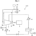
Fig. 1 is a schematic view illustrating a principal section of a refrigeration cycle system related to a first embodiment of the invention. -
Fig. 2 is a half-sectional view illustrating main parts of a compressor ofFig. 1 . -
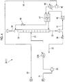
Fig. 3 is a schematic view illustrating a gas recovery system for a compressor related to the first embodiment of the invention. -
Fig. 4 is a schematic view illustrating a modification example of the gas recovery system for a compressor of the first embodiment. -
Fig. 5 is a view illustrating a gas recovery system for a compressor and main parts of the compressor related to a second embodiment of the invention. -
Fig. 6 is a schematic view illustrating a gas recovery system for a compressor related to a third embodiment of the invention. -
Fig. 7 is a view illustrating main parts of a compressor related to a fourth embodiment of the invention. Description of Embodiments - Hereinafter, embodiments for carrying out a gas recovery system for a compressor, a compressor system including the same, and a refrigeration cycle system according to the invention will be described with reference to the accompanying drawings. However, the invention is not limited only to these embodiments.
- As illustrated in
Fig. 1 , arefrigeration cycle system 1 related to a first embodiment of the invention is a system for cooling a cooling target (not illustrated). Aprincipal section 2 of therefrigeration cycle system 1 includes acompressor 3, a condenser 4, astorage portion 5, and an evaporator 6. These components are connected together by lines in the order listed above. - The
compressor 3 compresses a refrigerant (hereinafter referred to as a process gas) in a gas state. A drivingmachine 7, such as a motor, which drives a rotor 11 (refer toFig. 2 ) of thecompressor 3, is connected to the rotor. The condenser 4 cools and condenses a high-temperature and high-pressure process gas compressed in thecompressor 3. - The
storage portion 5 stores the process gas turning into a liquid state in the condenser 4. The evaporator 6 exchanges heat between the liquid process gas supplied from thestorage portion 5 in a state where pressure and temperature have dropped by adiabatically expanded by a valve 8, and a cooling target (not illustrated), and thus the evaporator evaporates (gasifies) the liquid process gas. The gasified process gas is again fed into thecompressor 3. - Although the above process gas may be, for example, hydrocarbon, the process gas of the present embodiment is Freon. The hydrocarbon used as the process gas may be one kind or a plurality of kinds of hydrocarbons appropriately selected from, for example, methane, ethane, propane, butane, and the like.
- As illustrated in
Figs. 1 and2 , therotor 11 of the above-mentionedcompressor 3 includes arotary shaft 13 and an impeller (not illustrated) attached to this rotary shaft. Astator 12 of thecompressor 3 includes a casing (not illustrated) that houses the impeller of therotor 11. Therotary shaft 13 has bothend portions stator 12 by abearing 14 outside the casing. Although a state where only thefirst end portion 13A of therotary shaft 13 in the axial direction is supported with respect to thestator 12 by thebearing 14 is described inFig. 2 , thesecond end portion 13B of therotary shaft 13 in the axial direction is similarly supported by thebearing 14. - A
seal portion 10 is provided in a gap between thestator 12 and therotor 11 in both theend portions rotary shaft 13. Theseal portion 10 includes a leakage preventingseal portion 15 that prevents the aforementioned process gas from leaking from the inside of the casing to the outside thereof. The leakage preventingseal portion 15 is located inside the casing from the bearing 14 in the axial direction of therotary shaft 13. - A
labyrinth seal 16 and adry gas seal 17 are included in the leakage preventingseal portion 15. In the present embodiment, afirst labyrinth seal 16A, a firstdry gas seal 17A, asecond labyrinth seal 16B, and a seconddry gas seal 17B are arrayed in order from the inside of the casing to the outside thereof in the axial direction of therotary shaft 13. - A process gas after a portion of the process gas compressed in the
compressor 3 has passed through a filter is supplied to a first space S1 between thefirst labyrinth seal 16A and the firstdry gas seal 17A as a sealing process gas G1. By supplying the sealing process gas G1 to the first space S1, the pressure of the first space S1 rises, and leakage of the process gas containing foreign matter larger than 3 µm from the inside of the casing to the first space S1 is prevented. - A
primary vent 18 for discharging a portion of a process gas that has leaked through the firstdry gas seal 17A from the first space S1 is connected to a second space S2 between the firstdry gas seal 17A and thesecond labyrinth seal 16B. The purity of a process gas G2 discharged from theprimary vent 18 is 100%. For this reason, the process gas G2 discharged from theprimary vent 18 is returned to theprincipal section 2 of therefrigeration cycle system 1 illustrated inFig. 1 after the pressure thereof is appropriately raised again. - Additionally, the
seal portion 10 includes aseparation seal 19 that is installed between the above-mentioned leakage preventingseal portion 15 andbearing 14. Theseparation seal 19 supplies a separation gas (supply gas) in a gas state, thereby preventing the lubricating oil used in the bearing 14 from being mixed into the leakage preventingseal portion 15 including thedry gas seal 17. - Although the separation gas used in the
separation seal 19 is supplied only from anexternal supply source 21 illustrated inFig. 1 , in the present embodiment, the separation gas recovered in a gas recovery system 30 (refer toFig. 3 ) to be described below is also used. Additionally, although the above separation gas just has to be an inert gas, for example, the separation gas may be a gas of which the boiling point is lower than that of the process gas. Although this kind of separation gas may be, for example, nitrogen, the separation gas of the present embodiment is carbon dioxide. - In a space S4 (hereinafter referred to as a mixing space S4) between the leakage preventing
seal portion 15 and theseparation seal 19 in the gap between thestator 12 and therotor 11, a minute amount of the process gas that has leaked from the leakage preventingseal portion 15, and the separation gas from theseparation seal 19 are mixed together. Asecondary vent 20 for discharging the mixed gas, in which the process gas and the separation gas are mixed together, from the mixing space S4 to thegas recovery system 30 to be described below, is connected to the mixing space S4. - Although only a state where components, such as the above-mentioned leakage preventing
seal portion 15 andseparation seal 19, are provided at thefirst end portion 13A of therotary shaft 13, is described inFig. 2 , the components, such as the leakage preventingseal portion 15 and theseparation seal 19, are similarly provided at thesecond end portion 13B of therotary shaft 13. - As illustrated in
Figs. 1 to 3 , therefrigeration cycle system 1 of the present embodiment includes thegas recovery system 30 for thecompressor 3 that separates the mixed gas discharged from thesecondary vent 20 of thecompressor 3 into the process gas and the separation gas and recovers the separated mixed gas. Thegas recovery system 30 includes a mixedgas supply line 31, adistillation column 32, a processgas recovery line 33, and a supplygas recovery line 34. - The mixed
gas supply line 31 is connected to thedistillation column 32 and supplies the mixed gas, which is discharged from thecompressor 3, to thedistillation column 32. The mixedgas supply line 31 of the present embodiment is connected to thesecondary vent 20 of theaforementioned compressor 3. The mixedgas supply line 31 of the present embodiment is provided with themixed gas compressor 35. Themixed gas compressor 35 raises the pressure of the mixed gas from the atmospheric pressure to a required pressure in thedistillation column 32. - The
distillation column 32 brings the separation gas in a liquid state into contact with the pressure-raised mixed gas, thereby exchanging heat between the mixed gas and the liquid separation gas to cool and liquefy the process gas contained in the mixed gas, and heat and gasify the liquid separation gas. - The
distillation column 32 of the present embodiment is formed to extend in an upward-downward direction and is formed in such a tubular shape that an upper part and a lower part thereof are blocked. InFig. 3 , although the aforementioned mixedgas supply line 31 is connected to an intermediate part of thedistillation column 32 in the upward-downward direction, the mixed gas supply line just has to be connected at a suitable height. - Additionally, in the
distillation column 32 of the present embodiment, the liquid separation gas is supplied to an upper part of thedistillation column 32, and for example, the liquid separation gas flows down from the upper part of thedistillation column 32 to a lower part thereof. Accordingly, heat exchange can be efficiently performed between the mixed gas and the liquid separation gas, and the process gas contained in the mixed gas can be efficiently is cooled and liquefied. Additionally, the liquid separation gas can be efficiently heated and gasified. - A supply source of the liquid separation gas supplied to the
distillation column 32 may be, for example, separately prepared, but in the present embodiment, the separation gas contained in the mixed gas is reused. - The process
gas recovery line 33 is connected to the lower part of thedistillation column 32 and recovers the liquid process gas discharged from the lower part of thedistillation column 32. The processgas recovery line 33 of the present embodiment is connected to theprincipal section 2 illustrated inFig. 1 , and recovers the process gas, which is recovered from thedistillation column 32, to theprincipal section 2. - Additionally, the process
gas recovery line 33 of the present embodiment is connected to a line between the evaporator 6 and thecompressor 3 of theprincipal section 2 such that the process gas recovered from thedistillation column 32 is again compressed in thecompressor 3 of theprincipal section 2. For this reason, in the processgas recovery line 33 of the present embodiment, the liquid process gas recovered from thedistillation column 32 is gasified using arecovery line valve 36 and a mixedgas heat exchanger 37 to be described below. - As illustrated in
Fig. 3 , the processgas recovery line 33 of the present embodiment is provided with therecovery line valve 36 that adjusts the amount of the liquid process gas, which is discharged from thedistillation column 32 to the processgas recovery line 33, to be returned to theprincipal section 2. In the present embodiment, the amount of the liquid process gas returned to theprincipal section 2 is adjusted by adjusting the opening degree of therecovery line valve 36 such that the liquid level of the liquid process gas in thedistillation column 32 is maintained within a predetermined range. Since the processgas recovery line 33 is connected to a place of theprincipal section 2 lower than the pressure in thedistillation column 32, therecovery line valve 36 adiabatically expands the liquid process gas that flows from thedistillation column 32. Accordingly, the pressure and temperature of the liquid process gas drop. - The supply
gas recovery line 34 is connected to the upper part of thedistillation column 32 and recovers the gaseous separation gas discharged from the upper part of thedistillation column 32. The supplygas recovery line 34 of the present embodiment is connected to theseparation seal 19 of thecompressor 3 illustrated inFig. 2 , and supplies the gaseous separation gas discharged from thedistillation column 32 again to theseparation seal 19. - Additionally, the
gas recovery system 30 of the present embodiment includes the mixedgas heat exchanger 37. The mixedgas heat exchanger 37 exchanges heat between the mixed gas flowing through the mixedgas supply line 31 and the process gas flowing through the processgas recovery line 33, thereby cooling the mixed gas. Since the temperature of the mixed gas is higher than that of the process gas flowing through the processgas recovery line 33, the mixed gas is supplied to thedistillation column 32 after being cooled in the mixedgas heat exchanger 37. - Particularly, in the present embodiment, the mixed
gas heat exchanger 37 is disposed closer to a downstream side (adistillation column 32 side) of the mixedgas supply line 31 than themixed gas compressor 35, and thus, the mixed gas passes through the mixedgas heat exchanger 37 in a state where the pressure of the mixed gas has been raised in themixed gas compressor 35 and the temperature thereof has risen. Additionally, in the present embodiment, the mixedgas heat exchanger 37 is disposed closer to a downstream side (aprincipal section 2 side of the refrigeration cycle system 1) than therecovery line valve 36, and thus the process gas flowing through the processgas recovery line 33 passes through the mixedgas heat exchanger 37 in a state where the temperature has dropped by the adiabatic expansion in therecovery line valve 36. - As a result, the mixed gas is cooled by the process gas flowing through the process
gas recovery line 33 in the mixedgas heat exchanger 37 and is supplied to thedistillation column 32, for example, in a gas-liquid mixed state. - Meanwhile, the liquid process gas discharged from the
distillation column 32 to the processgas recovery line 33 passes through the mixedgas heat exchanger 37 after being adiabatically expanded in therecovery line valve 36, and thus the process gas is heated and gasified by the mixed gas flowing through the mixedgas supply line 31. Accordingly, the process gas recovered from thedistillation column 32 can be supplied to thecompressor 3 in a gas state. - Additionally, the
gas recovery system 30 of the present embodiment includes anadditional supply line 38 for additionally supplying the liquid process gas to the processgas recovery line 33, between thedistillation column 32 and the mixedgas heat exchanger 37. Theadditional supply line 38 of the present embodiment is connected between therecovery line valve 36 in the processgas recovery line 33 and the mixedgas heat exchanger 37. - By adjusting the amount of the liquid process gas additionally supplied to the process
gas recovery line 33, it is possible to adjust the heat balance between the mixed gas and the process gas in the mixedgas heat exchanger 37 and to appropriately adjust such a degree that the mixed gas is cooled. In the present embodiment, theadditional supply line 38 is provided with anadjustment valve 38Z. By adjusting the opening degree of theadjustment valve 38Z, the amount of the liquid process gas additionally supplied to the processgas recovery line 33 can be adjusted. - The supply source of the liquid process gas additionally supplied to the process
gas recovery line 33 may be, for example, separately prepared, but is theprincipal section 2 of therefrigeration cycle system 1 illustrated inFig. 1 in the present embodiment. Theadditional supply line 38 may be connected to thestorage portion 5 of theprincipal section 2, for example, as illustrated inFigs. 1 and3 . In this case, the liquid process gas stored in thestorage portion 5 is supplied to the processgas recovery line 33 through theadditional supply line 38. - Moreover, in the
gas recovery system 30 of the present embodiment, the mixedgas heat exchanger 37 exchanges heat between the separation gas flowing through the supplygas recovery line 34 and the mixed gas flowing through the mixedgas supply line 31, thereby cooling the mixed gas. - Since the temperature of the mixed gas is higher than that of the separation gas flowing through the supply
gas recovery line 34, the mixed gas is supplied to thedistillation column 32 after being cooled by the separation gas flowing through the supplygas recovery line 34 in the mixedgas heat exchanger 37. - Additionally, the
gas recovery system 30 of the present embodiment includes a distillation column lower circulation line (process gas circulation line) 41 that branches from the processgas recovery line 33 and returns the liquid process gas, which is discharged from thedistillation column 32, to thedistillation column 32 after being gasified. - The distillation column
lower circulation line 41 of the present embodiment branches from the processgas recovery line 33 between thedistillation column 32 and therecovery line valve 36. Additionally, the distillation columnlower circulation line 41 is connected to the lower part of thedistillation column 32. Additionally, the liquid process gas flowing through the distillation columnlower circulation line 41 is gasified by using a circulation heat exchanger 47 (to be described below) in the present embodiment. - The distillation column
lower circulation line 41 of the present embodiment is provided with acirculation pump 42 for supplying the liquid process gas, which is discharged from thedistillation column 32, to thecirculation heat exchanger 47. - Additionally, the
gas recovery system 30 of the present embodiment includes a distillation column upper circulation line (supply gas circulation line) 44 that branches from the supplygas recovery line 34 and returns the gaseous separation gas discharged from thedistillation column 32 to thedistillation column 32 after being liquefied. The distillation columnupper circulation line 44 of the present embodiment branches from the supplygas recovery line 34 between thedistillation column 32 and the mixedgas heat exchanger 37. Additionally, the distillation columnupper circulation line 44 is connected to the upper part of thedistillation column 32. - In the distillation column
upper circulation line 44 of the present embodiment, the gaseous separation gas recovered from thedistillation column 32 is liquefied and returned to the upper part of thedistillation column 32 by using acirculation compressor 45, thecirculation heat exchanger 47, and acirculation valve 46 to be described below. - The distillation column
upper circulation line 44 of the present embodiment is provided with thecirculation compressor 45. Thecirculation compressor 45 returns the separation gas discharged from thedistillation column 32 to thedistillation column 32 after being drawn into the distillation columnupper circulation line 44 from the supplygas recovery line 34. Additionally, thecirculation compressor 45 raises the pressure of the separation gas. - Additionally, the
circulation valve 46 is provided between thecirculation compressor 45 in the distillation columnupper circulation lines 44 of the present embodiment and thedistillation column 32. Thecirculation valve 46 adjusts the discharge pressure of thecirculation compressor 45 by adjusting the opening degree thereof, and adiabatically expands the separation gas flowing through the distillation columnupper circulation line 44. Accordingly, the pressure and temperature of the separation gas raised in pressure and temperature by thecirculation compressor 45 drop. - A recovery valve that adjusts the amount of the gaseous separation gas, which is discharged from the
distillation column 32 to the supplygas recovery line 34, to be returned to theseparation seal 19 may be provided between a connected portion to the distillation columnupper circulation line 44 of the supplygas recovery line 34, and the mixedgas heat exchanger 37, like therecovery line valve 36 provided in the processgas recovery line 33. The opening degree of the recovery valve may be adjusted such that the pressure of the gas in thedistillation column 32 is maintained within a predetermined range, so that the amount of the gaseous separation gas returned to theseparation seal 19 can be adjusted. - Additionally, the
gas recovery system 30 of the present embodiment includes thecirculation heat exchanger 47. Thecirculation heat exchanger 47 exchanges heat between the liquid process gas flowing through the distillation columnlower circulation line 41 and the gaseous separation gas flowing through the distillation columnupper circulation line 44. - In the present embodiment, the separation gas passes through the
circulation heat exchanger 47 in a state where the separation gas is compressed in thecirculation compressor 45, that is, in a state the temperature of the separation gas has risen, and thus the temperature of the separation gas becomes higher than that of the process gas. - For this reason, in the
circulation heat exchanger 47, the liquid process gas flowing through the distillation columnlower circulation line 41 is heated by the gaseous separation gas flowing through the distillation columnupper circulation line 44. Accordingly, the liquid process gas flowing through the distillation columnlower circulation line 41 is gasified, and the gaseous process gas returns to the lower part of thedistillation column 32. - Additionally, in the
circulation heat exchanger 47, the gaseous separation gas flowing through the distillation columnupper circulation line 44 is cooled by the liquid process gas flowing through the distillation columnlower circulation line 41. Moreover, since the separation gas after being passed through thecirculation heat exchanger 47 is adiabatically expanded by passing through thecirculation valve 46, the liquefaction of the separation gas is promoted. Accordingly, the separation gas of which at least a portion has been turned into a liquid state returns from the distillation columnupper circulation line 44 to the upper part of thedistillation column 32. The liquid separation gas that has returned from the distillation columnupper circulation line 44 to the upper part of thedistillation column 32 is brought into contact with the mixed gas in thedistillation column 32 as mentioned above, thereby exchanging heat with the mixed gas. - The
gas recovery system 30 of the present embodiment configured as described above constitutes a compressor system together with thecompressor 3 of theprincipal section 2. - Next, the operation of the
gas recovery system 30 of the above configuration will be described. - A gaseous mixed gas discharged from the
secondary vent 20 of thecompressor 3 illustrated inFigs. 1 and2 flows through the mixedgas supply line 31 and is raised in pressure by themixed gas compressor 35. In this case, the temperature of the mixed gas also rises. The mixed gas of which pressure and temperature are raised in themixed gas compressor 35 is cooled by the process gas flowing through the processgas recovery line 33 and the separation gas flowing through the supplygas recovery line 34 by passing through the mixedgas heat exchanger 37, and thus the mixed gas is supplied to thedistillation column 32, for example, in a gas-liquid mixed state. - The mixed gas supplied to the
distillation column 32 is brought into contact with the liquid separation gas, thereby exchanging heat with the liquid separation gas. Accordingly, the process gas contained in the mixed gas is cooled and liquefied by the liquid separation gas. Meanwhile, the separation gas contained in the mixed gas in thedistillation column 32 is maintained in a gas state. Additionally, the liquid separation gas is heated and gasified by the process gas contained in the mixed gas. - The process gas (liquid process gas) liquefied in the
distillation column 32 is discharged from the lower part of thedistillation column 32 to the processgas recovery line 33. Additionally, the gaseous separation gas is discharged from the upper part of thedistillation column 32 to the supplygas recovery line 34. - At least a portion of the liquid process gas discharged to the process
gas recovery line 33 is drawn into the distillation columnlower circulation line 41 by thecirculation pump 42. The liquid process gas flowing through the distillation columnlower circulation line 41 passes through thecirculation heat exchanger 47, and thus the process gas is heated and gasified by the separation gas flowing through the distillation columnupper circulation line 44. Accordingly, the process gas flowing through the distillation columnlower circulation line 41 returns to the lower part of thedistillation column 32 in a gas state. - The gaseous process gas that has returned from the distillation column
lower circulation line 41 to thedistillation column 32 is again cooled and liquefied by the liquid separation gas, and is discharged from the lower part of thedistillation column 32 in a liquid state. Additionally, in a case where the gaseous separation gas is contained in the gaseous process gas that has returned from the distillation columnlower circulation line 41 to thedistillation column 32, this gaseous separation gas ascends to the upper part of thedistillation column 32, and is discharged from the upper part of thedistillation column 32 to the supplygas recovery line 34. Accordingly, the purity of the process gas in the lower part of thedistillation column 32 increases. - Additionally, at least a portion of the gaseous separation gas discharged from the upper part of the
distillation column 32 to the supplygas recovery line 34 is drawn into the distillation columnupper circulation line 44 by thecirculation compressor 45. The gaseous separation gas drawn into the distillation columnupper circulation line 44 is raised in pressure in thecirculation compressor 45, and subsequently, passes through thecirculation heat exchanger 47, and thus the separation gas is cooled by the process gas flowing through the distillation columnlower circulation line 41. Thereafter, since the separation gas flowing through the distillation columnupper circulation line 44 is cooled by being adiabatically expanded in thecirculation valve 46, the liquefaction of the separation gas is promoted. The separation gas after being passed through thecirculation valve 46 returns to the upper part of thedistillation column 32. - The liquid separation gas in the separation gas that has returned from the distillation column
upper circulation line 44 to thedistillation column 32 is again heated and gasified by the process gas contained in the mixed gas and the gaseous process gas that has returned from the distillation columnlower circulation line 41 to thedistillation column 32, and is discharged from the upper part of thedistillation column 32. - Additionally, the gaseous separation gas in the separation gas that has returned from the distillation column
upper circulation line 44 to thedistillation column 32, is discharged from the upper part of thedistillation column 32 as it is. Additionally, in a case where the process gas is contained in the separation gas that has returned from the distillation columnupper circulation line 44 to thedistillation column 32, this process gas is liquefied and is discharged from the lower part of thedistillation column 32. Accordingly, the purity of the separation gas in the upper part of thedistillation column 32 increases. - The liquid process gas, which is discharged from the lower part of the
distillation column 32 to the processgas recovery line 33 and flows through the processgas recovery line 33 without being drawn into the distillation columnlower circulation line 41, is adiabatically expanded in therecovery line valve 36, and thus the temperature thereof drops further. Next, the liquid process gas flowing through the processgas recovery line 33 passes through the mixedgas heat exchanger 37, and thus the process gas is heated and gasified by the mixed gas flowing through the mixedgas supply line 31. The gasified gaseous process gas is again supplied to thecompressor 3 of theprincipal section 2. - The gaseous separation gas, which is discharged from the upper part of the
distillation column 32 to the supplygas recovery line 34 and flows through the supplygas recovery line 34 without being drawn into the distillation columnupper circulation line 44, passes through the mixedgas heat exchanger 37, and thus the separation gas is heated by the mixed gas flowing through the mixedgas supply line 31. Thereafter, the heated gaseous separations gas is supplied to theseparation seal 19. - As described above, according to the
gas recovery system 30, the compressor system including the same and therefrigeration cycle system 1 in the present embodiment, the mixed gas discharged from thecompressor 3 is separated into the process gas and the separation gas in thedistillation column 32, and the process gas discharged from thedistillation column 32 is returned to thecompressor 3. Hence, the amount of the process gas additionally supplied to thecompressor 3 can be reduced. Additionally, since the separation gas discharged from thedistillation column 32 is also returned to theseparation seal 19 of thecompressor 3, the amount of the separation gas supplied from the external supply source to thecompressor 3 can be reduced. - From the above, the running cost of the
compressor 3 and therefrigeration cycle system 1 equipped with the compressor can be reduced. Particularly, in the present embodiment, since expensive Freon is used as the process gas, the running cost of thecompressor 3 and therefrigeration cycle system 1 can be effectively reduced. - Additionally, the
gas recovery system 30 of the present embodiment includes the distillation columnlower circulation line 41 that branches from the processgas recovery line 33 and returns the process gas, which is discharged from the lower part of thedistillation column 32, to thedistillation column 32 after being gasified. For this reason, it is possible to effectively reduce the amount of the separation gas contained in the liquid process gas discharged from thedistillation column 32 and to recover the process gas with high purity. - Additionally, the
gas recovery system 30 of the present embodiment includes the distillation columnupper circulation line 44 that branches from the supplygas recovery line 34 and returns the separation gas, which is discharged from the upper part of thedistillation column 32, to thedistillation column 32 after being liquefied. For this reason, it is possible to effectively reduce the amount of the process gas contained in the gaseous separation gas discharged from thedistillation column 32 and to recover the separation gas with high purity. - Additionally, since the separation gas separated from the mixed gas can be used as the liquid separation gas that exchanges heat with the mixed gas in the
distillation column 32, the running cost of thegas recovery system 30 can also be reduced. - Additionally, the
gas recovery system 30 of the present embodiment includes thecirculation heat exchanger 47 that exchanges heat between the process gas flowing through the distillation columnlower circulation line 41 and the separation gas flowing through the distillation columnupper circulation line 44. For this reason, in thecirculation heat exchanger 47, the liquid process gas flowing through the distillation columnlower circulation line 41 can be heated by the gaseous separation gas flowing through the distillation columnupper circulation line 44, so that the gasification of the process gas in the distillation columnlower circulation line 41 can be promoted. Additionally, in thecirculation heat exchanger 47, the gaseous separation gas flowing through the distillation columnupper circulation line 44 can be cooled by the liquid process gas flowing through the distillation columnlower circulation line 41, so that the liquefaction of the separation gas in the distillation columnupper circulation line 44 can be promoted. - Additionally, the heating of the process gas flowing through the distillation column
lower circulation line 41 and the cooling of the separation gas flowing through the distillation columnupper circulation line 44 are performed by the heat exchange between the process gas and the separation gas. That is, since the heating of the process gas and the cooling of the separation gas can be performed without using a separate heat source, the running cost of thegas recovery system 30 can be reduced. - Moreover, the
gas recovery system 30 of the present embodiment includes the mixedgas heat exchanger 37 that exchanges heat between the process gas flowing through the processgas recovery line 33 and the mixed gas flowing through the mixedgas supply line 31. Accordingly, since at least a portion of the mixed gas can be liquefied by cooling the mixed gas in the mixedgas heat exchanger 37, the mixed gas at least in a gas-liquid mixed state can be supplied to thedistillation column 32. Hence, in thedistillation column 32, the mixed gas can be efficiently separated into the process gas and the separation gas. - Additionally, since the mixed gas is cooled using the process gas flowing through the process gas recovery line 33 (that is, since the mixed gas is not cooled by a separate cooling source), the running cost of the
gas recovery system 30 can be reduced. - Additionally, according to the
gas recovery system 30 of the present embodiment, the liquid process gas is additionally supplied to the processgas recovery line 33 on the upstream side of the mixedgas heat exchanger 37. For this reason, in the mixedgas heat exchanger 37, it is possible to adjust the heat balance between the mixed gas flowing through the mixedgas supply line 31 and the process gas flowing through the processgas recovery line 33 and to appropriately adjust such a degree that the mixed gas is cooled. - Moreover, in the
gas recovery system 30 of the present embodiment, the separation gas flowing through the supplygas recovery line 34 also contributes to the cooling of the mixed gas flowing through the mixedgas supply line 31 in the mixedgas heat exchanger 37. For this reason, it is possible to reduce the amount of the liquid process gas additionally supplied to the processgas recovery line 33. - Additionally, in the
refrigeration cycle system 1 of the present embodiment, the carbon dioxide that is a kind of inert gas is used as the separation gas treated in thecompressor 3. Therefore, the mixed gas is suitably separable into liquid Freon and gaseous carbon dioxide in thedistillation column 32. - The
gas recovery system 30 of the above first embodiment may include aseparate cooling source 37A that cools the mixed gas flowing through the mixedgas supply line 31, for example, as illustrated inFig. 4 , instead of including the mixedgas heat exchanger 37. - Additionally, although the
gas recovery system 30 of the first embodiment may include, for example, a separate heating source that heats the process gas flowing through the processgas recovery line 33 or the separation gas flowing through the supplygas recovery line 34, thegas recovery system 30 may not include the heating source, for example, as illustrated inFig. 4 . In this case, the process gas that flows through the processgas recovery line 33 towards theprincipal section 2 is in a liquid state. For this reason, the processgas recovery line 33 may be connected to a line between the condenser 4 and thestorage portion 5 in theprincipal section 2 such that the liquid process gas is returned to theprincipal section 2. - Additionally, in the
circulation heat exchanger 47, in a case where a degree such that the gaseous separation gas flowing through the distillation columnupper circulation line 44 is cooled by the liquid process gas flowing through the distillation columnlower circulation line 41 is insufficient, specifically, in a case where the gaseous separation gas flowing through the distillation columnupper circulation line 44 is insufficiently cooled and is not liquefied even if the separation gas passes through thecirculation heat exchanger 47 and thecirculation valve 46, for example, as illustrated inFig. 4 , the gaseous separation gas may be cooled by the coolingsource 49 after having passed through thecirculation compressor 45. - Additionally, for example, the
circulation pump 42 may not be provided in the distillation columnlower circulation line 41. For example, the liquid process gas discharged from thedistillation column 32 to the distillation columnlower circulation line 41 may be supplied to thecirculation heat exchanger 47 by a liquid head difference in thedistillation column 32. - Additionally, the
gas recovery system 30 of the above first embodiment may include, for example, a separate heating source that heats the liquid process gas flowing through the distillation columnlower circulation line 41 and a separate cooling source that cools the gaseous separation gas flowing through the distillation columnupper circulation line 44, instead of including thecirculation heat exchanger 47. - Next, a second embodiment will be described with reference to
Fig. 5 . - In the second embodiment, the same constituent elements as those of the first embodiment will be designated by the same reference signs, and the detailed description thereof will be omitted.
- As illustrated in
Fig. 5 , in agas recovery system 30A related to the second embodiment of the invention, the separation gas is separated and recovered from a second mixed gas in which the separation gas (supply gas) from theseparation seal 19 and the lubricating oil from the bearing 14 of thecompressor 3 are mixed together. Hereinafter, this will be specifically described. - The second mixed gas is generated in a space S5 (hereinafter a second mixing space S5) between the
separation seal 19 and thebearing 14 in the gap between thestator 12 and therotor 11. Abearing vent 20A for discharging the second mixed gas to thegas recovery system 30A is connected to the second mixing space S5. - The
gas recovery system 30A illustrated inFig. 5 includes a second mixedgas supply line 31A, asecond distillation column 32A, and a second supplygas recovery line 34A, in addition to the same configuration as the first embodiment. - The second mixed
gas supply line 31A is connected to thebearing vent 20A of thecompressor 3 and thesecond distillation column 32A and supplies the second mixed gas, which is discharged from thecompressor 3, to thesecond distillation column 32A, like the mixedgas supply line 31 of the first embodiment. - The
second distillation column 32A brings the liquid separation gas into contact with the second mixed gas, thereby exchanging heat between the second mixed gas and the liquid separation gas to cool and liquefy the lubricating oil contained in the second mixed gas, and heat and gasify the liquid separation gas. - Although the
second distillation column 32A is simplified and described inFig. 5 , thesecond distillation column 32A is configured similarly to thedistillation column 32 of the first embodiment. For example, the liquefied lubricating oil is discharged from a lower part of thesecond distillation column 32A to a lubricatingoil recovery line 51. Additionally, the gaseous separation gas contained in the gasified separation gas and the second mixed gas is discharged from an upper part of thesecond distillation column 32A to the second supplygas recovery line 34A. - The gaseous separation gas discharged to the second supply
gas recovery line 34A is again supplied to theseparation seal 19. InFig. 5 , the second supplygas recovery line 34A is connected to the supplygas recovery line 34 but may be directly connected to, for example, theseparation seal 19. Although not illustrated inFig. 5 , a configuration in which the liquid separation gas is supplied to thesecond distillation column 32A may be the same distillation columnupper circulation line 44 or the like as that of the first embodiment. - According to the above-mentioned second embodiment, the same effects as those of the first embodiment are exhibited.
- That is, the second mixed gas in which the separation gas and the lubricating oil are mixed together in the
compressor 3 can be separated into the separation gas and the lubricating oil in thesecond distillation column 32A, and the separated separation gas can be reused as the gas supplied to theseparation seal 19 of thecompressor 3. Hence, the amount of the separation gas supplied from an external supply source to the compressor can be further reduced. - Next, a third embodiment will be described mainly with reference to
Fig. 6 . - In the third embodiment, the same constituent elements as those of the first embodiment will be designated by the same reference signs, and the detailed description thereof will be omitted.
- As illustrated in
Fig. 6 , in agas recovery system 30B related to the third embodiment of the invention, as in the first embodiment, the mixed gas in which the process gas and the separation gas (supply gas) supplied to the separation seal 19 (refer toFig. 2 ) of theseal portion 10 of thecompressor 3 are mixed together is separated into the process gas and the separation gas and recovered the separated gas. This will be specifically described below. - The
gas recovery system 30B of the present embodiment includes the same mixedgas supply line 31,distillation column 32, processgas recovery line 33, and supplygas recovery line 34 as those of the first embodiment. InFig. 6 , although description of respective halfway parts of the mixedgas supply line 31, the processgas recovery line 33, and the supplygas recovery line 34 are omitted, the respective halfway parts may be configured similarly to the aforementioned first embodiment (for example,Fig. 3 ), its modification example (for example,Fig. 4 ), and the like. - The
gas recovery system 30B of the present embodiment does not include the distillation column lower circulation line 41 (refer toFig. 3 ) of the first embodiment but includes a distillation column lower supply line (process gas supply line) 41B. The distillation columnlower supply line 41B supplies the gaseous process gas, which is treated in the compressor 3 (refer toFig. 1 ) of theprincipal section 2, to thedistillation column 32. - The gaseous process gas supplied to the
distillation column 32 may be, for example, a gaseous process gas before being taken into thecompressor 3 or may be, for example, a gaseous process gas after being compressed in thecompressor 3. That is, in theprincipal section 2 of therefrigeration cycle system 1, the distillation columnlower supply line 41B may be connected to, for example, a line that connects thecompressor 3 and the condenser 4 together, or may be connected to, for example, a line that connects the evaporator 6 and thecompressor 3 together (refer toFig. 1 ). - The distillation column
lower supply line 41B of the present embodiment is provided with an adjustment valve 41B1. By adjusting the opening degree of the adjustment valve 41B1, the amount of the gaseous process gas supplied to thedistillation column 32 can be adjusted. - Additionally, the
gas recovery system 30B of the present embodiment does not include the distillation column upper circulation line 44 (refer toFig. 3 ) of the first embodiment but includes a distillation column upper supply line (external supply line) 44B. The distillation columnupper supply line 44B supplies the liquid separation gas to thedistillation column 32. The liquid separation gas supplied to thedistillation column 32 just has to be supplied from, for example, anexternal supply source 21B illustrated inFig. 6 . Specific examples of theexternal supply source 21B include, for example, a storage portion that stores the separation gas in a liquid state, other facilities that treat separation gas, and the like. - The distillation column
upper supply line 44B of the present embodiment is provided with an adjustment valve 44B1. By adjusting the opening degree of the adjustment valve 44B1, the amount of the liquid separation gas supplied to thedistillation column 32 can be adjusted. - Additionally, the
gas recovery system 30B of the present embodiment includes a supplygas discharge line 61B that branches from the supplygas recovery line 34 and discharges a portion of the separation gas from the supplygas recovery line 34. The separation gas discharged to the supplygas discharge line 61B may be, for example, simply discharged to the outside or may be, for example, used as a gas for other facilities or gas for other plants. That is, the supplygas discharge line 61B may be, for example, open to the atmosphere, or may be, for example, connected to other facilities or plants. - Additionally, the supply
gas discharge line 61B of the present embodiment is provided with a discharge valve 61B1. The opening degree of the discharge valve 61B1 may be adjusted, for example, such that the pressure in the supplygas recovery line 34 is maintained within a predetermined range. - According to the above-mentioned third embodiment, the same effects as those of the first embodiment are exhibited.
- That is, according to the
gas recovery system 30B of the third embodiment, the distillation columnlower supply line 41B is included instead of the distillation columnlower circulation line 41 of the first embodiment, so that the purity of the liquid process gas discharged from thedistillation column 32 can be enhanced. That is, the process gas with high purity can be recovered from the mixed gas. - Additionally, the distillation column
lower supply line 41B of the present embodiment is provided instead of the distillation columnlower circulation line 41 of the first embodiment. For this reason, it is not necessary to provide thegas recovery system 30B of the present embodiment with a heating source (for example, thecirculation heat exchanger 47 inFig. 3 , or the like) that heats the process gas flowing through the distillation columnlower circulation line 41 like the first embodiment. Hence, thegas recovery system 30B can be simply configured, and additionally, the manufacturing cost of thegas recovery system 30B can be reduced. - Additionally, according to the
gas recovery system 30B of the third embodiment, the distillation columnupper supply line 44B is included instead of the distillation columnupper circulation line 44 of the first embodiment, so that the purity of the gaseous separation gas discharged from thedistillation column 32 can be enhanced. That is, it is possible to recover the separation gas with high purity from the mixed gas. - Additionally, the distillation column
upper supply line 44B of the present embodiment is provided instead of the distillation columnupper circulation line 44 of the first embodiment. For this reason, it is not necessary to provide thegas recovery system 30B of the present embodiment with a cooling source (for example, thecirculation heat exchanger 47 inFig. 3 , the coolingsource 49 inFig. 4 , or the like) that cools the separation gas flowing through the distillation columnupper circulation line 44 like the first embodiment. Hence, thegas recovery system 30B can be simply configured, and additionally, the manufacturing cost of thegas recovery system 30B can be reduced. - Additionally, according to the
gas recovery system 30B of the present embodiment, a portion of the separation gas flowing through the supplygas recovery line 34 can be discharged to the supplygas discharge line 61B. For this reason, even if the separation gas is supplied to thedistillation column 32 through the distillation columnupper supply line 44B, the amount of the separation gas supplied to the separation seal 19 (refer toFig. 2 ) can be prevented from becoming excessive. - The configuration of the above-mentioned third embodiment may be appropriately combined with the configuration of the aforementioned first embodiment or the configuration of the aforementioned second embodiment.
- That is, the gas recovery system of the invention may include, for example, the distillation column
lower circulation line 41 and the distillation columnupper supply line 44B, or may include, for example, the distillation columnlower supply line 41B and the distillation columnupper circulation line 44. - Additionally, the
gas recovery system 30B of the third embodiment may be applied to, for example, thegas recovery system 30A of the second embodiment. - Next, a fourth embodiment will be described mainly with reference to
Fig. 7 . - In the fourth embodiment, the same constituent elements as those of the first embodiment will be designated by the same reference signs, and the detailed description thereof will be omitted. In the fourth embodiment, the site of the
seal portion 10 of thecompressor 3 that supplies the supply gas treated in the gas recovery system is different from that of the first embodiment. - As illustrated in
Fig. 7 , theseal portion 10 related to the fourth embodiment of the invention includes the same leakage preventingseal portion 15 as that of the first embodiment. Additionally, the leakage preventingseal portion 15 includes a plurality of dry gas seals 17 arrayed in order from the inside of the casing to the outside thereof in the axial direction of therotary shaft 13, as in the first embodiment. The plurality of dry gas seals 17 in the present embodiment are the same firstdry gas seal 17A and seconddry gas seal 17B as those of the first embodiment. - Between the two
dry gas seals second labyrinth seal 16B as that of the first embodiment is provided. For this reason, the second space S2 is formed between the firstdry gas seal 17A and thesecond labyrinth seal 16B, and a third space S3 is formed between thesecond labyrinth seal 16B and the seconddry gas seal 17B. Thesecond labyrinth seal 16B may be, for example, a barrier seal. - In the present embodiment, the supply gas treated in the same
gas recovery system 30 as that of the first embodiment is not the separation gas illustrated in the first to third embodiments and is a seal gas supplied between the firstdry gas seal 17A and the seconddry gas seal 17B. In the present embodiment, a seal gas is supplied to the third space S3 between thesecond labyrinth seal 16B and the seconddry gas seal 17B. Accordingly, the pressure of the third space S3 rises, and the process gas that has leaked from the first space S1 through the firstdry gas seal 17A to the second space S2 is prevented from leaking through thesecond labyrinth seal 16B to the third space S3. - The seal gas supplied between the first
dry gas seal 17A and the seconddry gas seal 17B includes at least the seal gas recovered in the same gas recovery system 30 (refer toFig. 3 ) as that of the first embodiment. For this reason, the same supplygas recovery line 34 as that of the first embodiment is connected between the firstdry gas seal 17A and the seconddry gas seal 17B. In the present embodiment, the supplygas recovery line 34 is connected to the third space S3. - Additionally, the seal gas supplied between the first
dry gas seal 17A and the seconddry gas seal 17B may also include, for example, the seal gas from theexternal supply source 21 illustrated inFig. 1 , in addition to the seal gas from thegas recovery system 30. - As in the first embodiment, the process gas in the present embodiment may be, for example, Freon or may be, for example, hydrocarbon.
- Meanwhile, the above-mentioned seal gas may be, for example, gas of which the boiling point is lower than that of the process gas, similar to the separation gas in the first embodiment. The seal gas in the present embodiment may be, for example, carbon dioxide or may be, for example, hydrocarbon.
- In the aforementioned second space S2 (hereinafter referred to as a mixing space S2), the process gas that has leaked from the first
dry gas seal 17A and the supplied seal gas are mixed together. Aprimary vent 18C for discharging the mixed gas, in which the process gas and the seal gas are mixed together, from the mixing space S2 to the samegas recovery system 30 as that of the first embodiment is connected to the mixing space S2. That is, theprimary vent 18C is connected to the mixedgas supply line 31. - Additionally, the
seal portion 10 of the present embodiment includes thesame separation seal 19 as that of the first embodiment. In the present embodiment, the separation gas is supplied only from anexternal supply source 71 to theseparation seal 19. The separation gas just has to be at least inert gas. Although the separation gas may be, for example, carbon dioxide, the separation gas is nitrogen more inexpensive than the carbon dioxide in the present embodiment. - In the present embodiment, the seal gas (supply gas) that has leaked from the leakage preventing
seal portion 15, and the separation gas from theseparation seal 19 are mixed together in the mixing space S4 between the leakage preventingseal portion 15 and theseparation seal 19. - A
secondary vent 20C for discharging a mixed gas G4, in which the seal gas and the separation gas are mixed together, from the mixing space S4 to the outside (for example, opening to the atmosphere) is connected to the mixing space S4 of the present embodiment. - According to the above-mentioned fourth embodiment, the same effects as those of the first embodiment are exhibited.
- That is, even if the seal gas supplied between the adjacent
dry gas seals dry gas seals compressor 3. Hence, the amount of the seal gas supplied from the external supply source to thecompressor 3 can be reduced. - Additionally, according to the fourth embodiment, the seal gas is supplied between the adjacent
dry gas seals dry gas seal 17B and thebearing 14. For this reason, even if the seal gas is hydrocarbon, the hydrocarbon can be prevented from reaching the bearing 14 located outside theseal portion 10. Accordingly, mixing of the hydrocarbon, which is a combustible gas, into a lubricating oil supply system can be prevented. - The configuration of the above-mentioned fourth embodiment is not limited to being applied to the
gas recovery system 30 of the first embodiment and can be applied to, for example, thegas recovery system 30B of the third embodiment. - For example, in the
gas recovery system 30B of the third embodiment to which the configuration of the fourth embodiment is applied, in a case where the liquid seal gas (supply gas) supplied from theexternal supply source 21B through the distillation columnupper supply line 44B to thedistillation column 32 is hydrocarbon, theexternal supply source 21B may be, for example, a liquefied natural gas (LNG) plant that purifies LNG. That is, the liquid seal gas (hydrocarbon) supplied to thedistillation column 32 may be, for example, LNG purified in the LNG plant. - Since the
refrigeration cycle system 1 illustrated inFig. 1 is also provided in the LNG plant, the purified LNG can be effectively used as the liquid seal gas supplied to thedistillation column 32. - Additionally, in the
gas recovery system 30B of the third embodiment to which the configuration of the fourth embodiment is applied, in a case where the gaseous seal gas discharged from thedistillation column 32 to the supplygas discharge line 61B is hydrocarbon, the seal gas (hydrocarbon) discharged to the supplygas discharge line 61B may be incinerated and disposed as, for example, gas flare, or may be used as, for example, fuel gas. - Although the invention has been described above in detail, the invention is not limited to the above-described embodiments, and various changes can be added without departing from the scope of the invention.
- Additionally, the gas recovery system of the invention is not limited to being provided in the
refrigeration cycle system 1 of the above embodiment and can be provided for at least a compressor that discharges a mixed gas. -
- 1: REFRIGERATION CYCLE SYSTEM
- 2: PRINCIPAL SECTION
- 3: COMPRESSOR
- 4: CONDENSER
- 5: STORAGE PORTION
- 6: EVAPORATOR
- 7: DRIVING MACHINE
- 10: SEAL PORTION
- 11: ROTOR
- 12: STATOR
- 13: ROTARY SHAFT
- 14: BEARING
- 15: LEAKAGE PREVENTING SEAL PORTION
- 17, 17A, 17B: DRY GAS SEAL
- 18, 18C: PRIMARY VENT
- 19: SEPARATION SEAL
- 20, 20C: SECONDARY VENT
- 20A: BEARING VENT
- 30, 30A, 30B: GAS RECOVERY SYSTEM
- 31: MIXED GAS SUPPLY LINE
- 31A: SECOND MIXED GAS SUPPLY LINE
- 32: DISTILLATION COLUMN
- 32A: SECOND DISTILLATION COLUMN
- 33: PROCESS GAS RECOVERY LINE
- 34: SUPPLY GAS RECOVERY LINE
- 34A: SECOND SUPPLY GAS RECOVERY LINE
- 35: MIXED GAS COMPRESSOR
- 36: RECOVERY LINE VALVE
- 37: MIXED GAS HEAT EXCHANGER
- 38: ADDITIONAL SUPPLY LINE
- 41: DISTILLATION COLUMN LOWER CIRCULATION LINE (PROCESS GAS CIRCULATION LINE)
- 41B: DISTILLATION COLUMN LOWER SUPPLY LINE (PROCESS GAS SUPPLY LINE)
- 42: CIRCULATION PUMP
- 44: DISTILLATION COLUMN UPPER CIRCULATION LINE (SUPPLY GAS CIRCULATION LINE)
- 44B: DISTILLATION COLUMN UPPER SUPPLY LINE (EXTERNAL SUPPLY LINE)
- 45: CIRCULATION COMPRESSOR
- 46: CIRCULATION VALVE
- 47: CIRCULATION HEAT EXCHANGER
- 61B: SUPPLY GAS DISCHARGE LINE
- S2: SECOND SPACE (MIXING SPACE)
- S4: MIXING SPACE
Claims (15)
- A gas recovery system for a compressor that separates a mixed gas, in which a process gas compressed by a compressor is mixed with a supply gas supplied to a seal portion of the compressor, into the process gas and the supply gas and recovers the mixed gas, the gas recovery system for a compressor comprising:a distillation column that brings the supply gas in a liquid state into contact with the mixed gas, thereby exchanging heat between the mixed gas and the liquid supply gas to cool and liquefy a process gas contained in the mixed gas, and heat and gasify the liquid supply gas;a process gas recovery line that is connected to a lower part of the distillation column and recovers the liquid process gas discharged from the lower part of the distillation column; anda supply gas recovery line that is connected to an upper part of the distillation column and recovers the supply gas in a gas state discharged from the upper part of the distillation column.
- The gas recovery system for a compressor according to Claim 1,
wherein the process gas is Freon or hydrocarbon, and the supply gas is carbon dioxide or hydrocarbon. - The gas recovery system for a compressor according to Claim 1 or 2, further comprising:a process gas circulation line that branches from the process gas recovery line and returns the liquid process gas, which is discharged from the distillation column, to the distillation column after being gasified.
- The gas recovery system for a compressor according to Claim 1 or 2, further comprising:a process gas supply line that supplies the gaseous process gas, which is treated in the compressor, to the distillation column.
- The gas recovery system for a compressor according to any one of Claims 1 to 4, further comprising:a supply gas circulation line that branches from the supply gas recovery line and returns the gaseous supply gas, which is discharged from the distillation column, to the distillation column after being liquefied.
- The gas recovery system for a compressor according to any one of Claims 1 to 4, further comprising:an external supply line that supplies the liquid supply gas to the distillation column.
- The gas recovery system for a compressor according to Claim 1 or 2, further comprising:a process gas circulation line that branches from the process gas recovery line and returns the process gas in a liquid state, which is discharged from the distillation column, to the distillation column after being gasified;a supply gas circulation line that branches from the supply gas recovery line and returns the gaseous supply gas, which is discharged from the distillation column, to the distillation column after being liquefied; anda circulation heat exchanger that exchanges heat between the liquid process gas flowing through the process gas circulation line and the gaseous supply gas flowing through the supply gas circulation line.
- The gas recovery system for a compressor according to any one of Claims 1 to 7, further comprising:a mixed gas supply line that is connected to the distillation column and supplies the mixed gas to the distillation column; anda mixed gas heat exchanger that exchanges heat between the process gas flowing through the process gas recovery line and the mixed gas flowing through the mixed gas supply line, thereby cooling the mixed gas with the process gas flowing through the process gas recovery line.
- The gas recovery system for a compressor according to Claim 8, further comprising:an additional supply line for additionally supplying the liquid process gas to the process gas recovery line, between the distillation column and the mixed gas heat exchanger.
- The gas recovery system for a compressor according to Claim 9,
wherein the mixed gas heat exchanger exchanges heat between the supply gas flowing through the supply gas recovery line and the mixed gas flowing through the mixed gas supply line, thereby cooling the mixed gas with the supply gas flowing through the supply gas recovery line. - The gas recovery system for a compressor according to any one of Claims 1 to 10,
wherein the seal portion includes a dry gas seal, and a separation seal installed between a bearing of the compressor and the dry gas seal, and the supply gas is a separation gas supplied to the separation seal. - The gas recovery system for a compressor according to Claim 11, further comprising:a second distillation column that brings the separation gas in a liquid state into a second mixed gas in which the separation gas is mixed with lubricating oil from the bearing of the compressor, thereby exchanging heat between the second mixed gas and the liquid separation gas to cool and liquefy the lubricating oil contained in the second mixed gas, and heat and gasify the liquid separation gas; anda second supply gas recovery line that is connected to an upper part of the second distillation column and recovers the separation gas in a gas state discharged from the upper part of the distillation column.
- The gas recovery system for a compressor according to any one of Claims 1 to 10,
wherein the seal portion includes a plurality of dry gas seals, and the supply gas is a seal gas supplied between the dry gas seals adjacent to each other. - A compressor system comprising:a compressor; andthe gas recovery system for a compressor according to any one of Claims 1 to 13.
- A refrigeration cycle system comprising:the compressor system according to Claim 14.
Applications Claiming Priority (2)
| Application Number | Priority Date | Filing Date | Title |
|---|---|---|---|
| PCT/JP2014/084606 WO2016103479A1 (en) | 2014-12-26 | 2014-12-26 | Gas recovery system for compressor, compressor system, and refrigeration cycle system |
| PCT/JP2015/059144 WO2016103744A1 (en) | 2014-12-26 | 2015-03-25 | Gas recovery system for compressor, compressor system, and refrigeration cycle system |
Publications (3)
| Publication Number | Publication Date |
|---|---|
| EP3225940A1 true EP3225940A1 (en) | 2017-10-04 |
| EP3225940A4 EP3225940A4 (en) | 2018-01-03 |
| EP3225940B1 EP3225940B1 (en) | 2019-09-04 |
Family
ID=56149564
Family Applications (1)
| Application Number | Title | Priority Date | Filing Date |
|---|---|---|---|
| EP15872314.8A Active EP3225940B1 (en) | 2014-12-26 | 2015-03-25 | Gas recovery system for compressor, compressor system, and refrigeration cycle system |
Country Status (4)
| Country | Link |
|---|---|
| US (1) | US11067320B2 (en) |
| EP (1) | EP3225940B1 (en) |
| JP (1) | JP6323965B2 (en) |
| WO (2) | WO2016103479A1 (en) |
Cited By (4)
| Publication number | Priority date | Publication date | Assignee | Title |
|---|---|---|---|---|
| EP3264011A4 (en) * | 2015-04-27 | 2018-01-17 | Mitsubishi Heavy Industries Compressor Corporation | Gas recovery system, compressor system, and refrigeration cycle system |
| CN110345707A (en) * | 2019-06-28 | 2019-10-18 | 张家港市江南利玛特设备制造有限公司 | A kind of multi-stage condensing system and multi-stage condensing method for petroleum vapor recovery |
| IT202000011326A1 (en) * | 2020-05-15 | 2021-11-15 | Sime S R L | APPARATUS AND METHOD FOR LIMITING WORKING FLUID LOSSES IN A REFRIGERATING PLANT |
| EP4490485A4 (en) * | 2022-03-11 | 2026-04-15 | Atlas Copco Mafi Trench Company Llc | THERMALLY INSULATING SEALING SYSTEM AND METHOD |
Families Citing this family (5)
| Publication number | Priority date | Publication date | Assignee | Title |
|---|---|---|---|---|
| US20190056175A1 (en) * | 2017-08-21 | 2019-02-21 | GE Oil & Gas, LLC | Refrigerant and nitrogen recovery |
| EP3933208A4 (en) * | 2019-02-25 | 2022-11-23 | IHI Corporation | Sealing device and compound pump |
| CN113122301A (en) * | 2021-04-27 | 2021-07-16 | 山西沃能化工科技有限公司 | Oil-gas separation and recovery method for dry gas seal leakage gas of centrifugal compressor |
| CN113958872B (en) * | 2021-10-15 | 2025-04-22 | 国家石油天然气管网集团有限公司 | Dry Gas Seal Compressor Leakage Recovery System |
| FR3140938B1 (en) | 2022-10-17 | 2024-11-01 | Air Liquide | Gas recovery process and apparatus for compressor |
Family Cites Families (17)
| Publication number | Priority date | Publication date | Assignee | Title |
|---|---|---|---|---|
| US3186182A (en) * | 1963-05-27 | 1965-06-01 | Phillips Petroleum Co | Low-temperature, low-pressure separation of gases |
| US3524897A (en) * | 1963-10-14 | 1970-08-18 | Lummus Co | Lng refrigerant for fractionator overhead |
| JPS4934211B1 (en) * | 1970-12-16 | 1974-09-12 | ||
| JPS4929221B1 (en) * | 1970-12-16 | 1974-08-02 | ||
| US4311004A (en) | 1979-10-26 | 1982-01-19 | Rotoflow Corporation | Gas compression system and method |
| US4495035A (en) * | 1981-03-06 | 1985-01-22 | Swearingen Judson S | Fluid handling method with improved purification |
| JPH0765585B2 (en) * | 1988-09-28 | 1995-07-19 | 株式会社日立製作所 | Dry screw vacuum pump for semiconductor manufacturing equipment |
| GB2297825A (en) * | 1995-02-03 | 1996-08-14 | Air Prod & Chem | Process to remove nitrogen from natural gas |
| CA2222632C (en) | 1995-06-19 | 2000-11-21 | Climate Supply (Atlantic) Inc. | Refrigerant separation system |
| JP2001107891A (en) * | 1999-10-07 | 2001-04-17 | Mitsubishi Heavy Ind Ltd | Centrifugal multi-stage compressor |
| JP3729496B2 (en) * | 2002-09-26 | 2005-12-21 | 阿部化学 株式会社 | Recovered refrigerant regeneration device |
| JP3816066B2 (en) * | 2003-06-17 | 2006-08-30 | 大旺建設株式会社 | Recycled recovered CFCs |
| US8061984B2 (en) * | 2009-04-06 | 2011-11-22 | Dresser-Rand Company | Dry gas blow down seal |
| IT1397059B1 (en) * | 2009-11-23 | 2012-12-28 | Nuovo Pignone Spa | SEAL SYSTEM FOR DRY GAS, LOW EMISSION FOR COMPRESSORS |
| FR2953913B1 (en) | 2009-12-11 | 2012-01-13 | Air Liquide | METHOD AND DEVICE FOR COOLING / LIQUEFACTION AT LOW TEMPERATURE |
| JP5419720B2 (en) * | 2010-01-13 | 2014-02-19 | 三菱重工コンプレッサ株式会社 | Seal gas temperature control device for butadiene gas compressor |
| CA2790961C (en) | 2012-05-11 | 2019-09-03 | Jose Lourenco | A method to recover lpg and condensates from refineries fuel gas streams. |
-
2014
- 2014-12-26 WO PCT/JP2014/084606 patent/WO2016103479A1/en not_active Ceased
-
2015
- 2015-03-25 WO PCT/JP2015/059144 patent/WO2016103744A1/en not_active Ceased
- 2015-03-25 EP EP15872314.8A patent/EP3225940B1/en active Active
- 2015-03-25 JP JP2016565941A patent/JP6323965B2/en not_active Expired - Fee Related
- 2015-03-25 US US15/538,436 patent/US11067320B2/en active Active
Cited By (6)
| Publication number | Priority date | Publication date | Assignee | Title |
|---|---|---|---|---|
| EP3264011A4 (en) * | 2015-04-27 | 2018-01-17 | Mitsubishi Heavy Industries Compressor Corporation | Gas recovery system, compressor system, and refrigeration cycle system |
| US10337779B2 (en) | 2015-04-27 | 2019-07-02 | Mitsubishi Heavy Industries Compressor Corporation | Gas recovery system, compressor system, and refrigeration cycle system |
| CN110345707A (en) * | 2019-06-28 | 2019-10-18 | 张家港市江南利玛特设备制造有限公司 | A kind of multi-stage condensing system and multi-stage condensing method for petroleum vapor recovery |
| CN110345707B (en) * | 2019-06-28 | 2020-11-17 | 张家港市江南利玛特设备制造有限公司 | Multistage condensation system and multistage condensation method for oil gas recovery |
| IT202000011326A1 (en) * | 2020-05-15 | 2021-11-15 | Sime S R L | APPARATUS AND METHOD FOR LIMITING WORKING FLUID LOSSES IN A REFRIGERATING PLANT |
| EP4490485A4 (en) * | 2022-03-11 | 2026-04-15 | Atlas Copco Mafi Trench Company Llc | THERMALLY INSULATING SEALING SYSTEM AND METHOD |
Also Published As
| Publication number | Publication date |
|---|---|
| WO2016103744A1 (en) | 2016-06-30 |
| US11067320B2 (en) | 2021-07-20 |
| EP3225940B1 (en) | 2019-09-04 |
| WO2016103479A1 (en) | 2016-06-30 |
| US20170343257A1 (en) | 2017-11-30 |
| JPWO2016103744A1 (en) | 2017-09-28 |
| EP3225940A4 (en) | 2018-01-03 |
| JP6323965B2 (en) | 2018-05-16 |
Similar Documents
| Publication | Publication Date | Title |
|---|---|---|
| EP3225940B1 (en) | Gas recovery system for compressor, compressor system, and refrigeration cycle system | |
| JP6362292B2 (en) | Gas recovery system, compressor system and refrigeration cycle system | |
| JP6923629B2 (en) | Generation of low-pressure liquid carbon dioxide from power generation systems and methods | |
| US9841230B2 (en) | System for enhanced gas turbine performance in a liquefied natural gas facility | |
| RU2743095C2 (en) | Method for liquefying natural gas and extracting liquids contained therein including two semi-closed natural gas refrigeration cycles and closed refrigerant gas refrigeration cycle | |
| RU2205337C2 (en) | Updated method of liquefaction of natural gas | |
| JP5877451B2 (en) | Apparatus and method using a multi-stage cryogenic hydraulic turbine | |
| ES2665719T3 (en) | Production procedure of liquid and gaseous nitrogen streams, a helium rich gas stream and a denitrogenated stream and associated installation | |
| RU2727500C1 (en) | Improved method and system for cooling hydrocarbon flow using gas-phase coolant | |
| BR0315890B1 (en) | Process and apparatus for liquefying natural gas | |
| RU2743094C2 (en) | Improved method and system for cooling a hydrocarbon flow using a gas-phase coolant | |
| BR112019017533B1 (en) | NATURAL GAS BLENDING SYSTEM | |
| KR20100093074A (en) | Method and apparatus for cooling and liquefying a hydrocarbon stream | |
| US20230168029A1 (en) | Refrigerant and nitrogen recovery | |
| US11097220B2 (en) | Method of preparing natural gas to produce liquid natural gas (LNG) | |
| AU2007291276A1 (en) | Method and apparatus for generating a gaseous hydrocarbon stream from a liquefied hydrocarbon stream | |
| CA2935708C (en) | A method to recover and process methane and condensates from flare gas systems | |
| KR20250062996A (en) | Natural gas liquefaction apparatus |
Legal Events
| Date | Code | Title | Description |
|---|---|---|---|
| STAA | Information on the status of an ep patent application or granted ep patent |
Free format text: STATUS: THE INTERNATIONAL PUBLICATION HAS BEEN MADE |
|
| PUAI | Public reference made under article 153(3) epc to a published international application that has entered the european phase |
Free format text: ORIGINAL CODE: 0009012 |
|
| STAA | Information on the status of an ep patent application or granted ep patent |
Free format text: STATUS: REQUEST FOR EXAMINATION WAS MADE |
|
| 17P | Request for examination filed |
Effective date: 20170620 |
|
| AK | Designated contracting states |
Kind code of ref document: A1 Designated state(s): AL AT BE BG CH CY CZ DE DK EE ES FI FR GB GR HR HU IE IS IT LI LT LU LV MC MK MT NL NO PL PT RO RS SE SI SK SM TR |
|
| AX | Request for extension of the european patent |
Extension state: BA ME |
|
| A4 | Supplementary search report drawn up and despatched |
Effective date: 20171130 |
|
| RIC1 | Information provided on ipc code assigned before grant |
Ipc: F25B 43/02 20060101ALI20171124BHEP Ipc: F25J 3/02 20060101ALI20171124BHEP Ipc: F25B 45/00 20060101AFI20171124BHEP Ipc: F25J 1/02 20060101ALI20171124BHEP Ipc: F04D 29/10 20060101ALI20171124BHEP Ipc: F04D 29/16 20060101ALI20171124BHEP Ipc: F25J 5/00 20060101ALI20171124BHEP Ipc: F25B 31/00 20060101ALI20171124BHEP |
|
| DAV | Request for validation of the european patent (deleted) | ||
| DAX | Request for extension of the european patent (deleted) | ||
| STAA | Information on the status of an ep patent application or granted ep patent |
Free format text: STATUS: EXAMINATION IS IN PROGRESS |
|
| 17Q | First examination report despatched |
Effective date: 20180801 |
|
| GRAP | Despatch of communication of intention to grant a patent |
Free format text: ORIGINAL CODE: EPIDOSNIGR1 |
|
| STAA | Information on the status of an ep patent application or granted ep patent |
Free format text: STATUS: GRANT OF PATENT IS INTENDED |
|
| INTG | Intention to grant announced |
Effective date: 20190220 |
|
| GRAJ | Information related to disapproval of communication of intention to grant by the applicant or resumption of examination proceedings by the epo deleted |
Free format text: ORIGINAL CODE: EPIDOSDIGR1 |
|
| STAA | Information on the status of an ep patent application or granted ep patent |
Free format text: STATUS: EXAMINATION IS IN PROGRESS |
|
| GRAR | Information related to intention to grant a patent recorded |
Free format text: ORIGINAL CODE: EPIDOSNIGR71 |
|
| GRAS | Grant fee paid |
Free format text: ORIGINAL CODE: EPIDOSNIGR3 |
|
| INTC | Intention to grant announced (deleted) | ||
| STAA | Information on the status of an ep patent application or granted ep patent |
Free format text: STATUS: GRANT OF PATENT IS INTENDED |
|
| GRAA | (expected) grant |
Free format text: ORIGINAL CODE: 0009210 |
|
| STAA | Information on the status of an ep patent application or granted ep patent |
Free format text: STATUS: THE PATENT HAS BEEN GRANTED |
|
| INTG | Intention to grant announced |
Effective date: 20190724 |
|
| AK | Designated contracting states |
Kind code of ref document: B1 Designated state(s): AL AT BE BG CH CY CZ DE DK EE ES FI FR GB GR HR HU IE IS IT LI LT LU LV MC MK MT NL NO PL PT RO RS SE SI SK SM TR |
|
| REG | Reference to a national code |
Ref country code: GB Ref legal event code: FG4D |
|
| REG | Reference to a national code |
Ref country code: CH Ref legal event code: EP |
|
| REG | Reference to a national code |
Ref country code: AT Ref legal event code: REF Ref document number: 1175936 Country of ref document: AT Kind code of ref document: T Effective date: 20190915 |
|
| REG | Reference to a national code |
Ref country code: DE Ref legal event code: R096 Ref document number: 602015037514 Country of ref document: DE |
|
| REG | Reference to a national code |
Ref country code: IE Ref legal event code: FG4D |
|
| REG | Reference to a national code |
Ref country code: NL Ref legal event code: MP Effective date: 20190904 |
|
| REG | Reference to a national code |
Ref country code: LT Ref legal event code: MG4D |
|
| PG25 | Lapsed in a contracting state [announced via postgrant information from national office to epo] |
Ref country code: NO Free format text: LAPSE BECAUSE OF FAILURE TO SUBMIT A TRANSLATION OF THE DESCRIPTION OR TO PAY THE FEE WITHIN THE PRESCRIBED TIME-LIMIT Effective date: 20191204 Ref country code: SE Free format text: LAPSE BECAUSE OF FAILURE TO SUBMIT A TRANSLATION OF THE DESCRIPTION OR TO PAY THE FEE WITHIN THE PRESCRIBED TIME-LIMIT Effective date: 20190904 Ref country code: FI Free format text: LAPSE BECAUSE OF FAILURE TO SUBMIT A TRANSLATION OF THE DESCRIPTION OR TO PAY THE FEE WITHIN THE PRESCRIBED TIME-LIMIT Effective date: 20190904 Ref country code: LT Free format text: LAPSE BECAUSE OF FAILURE TO SUBMIT A TRANSLATION OF THE DESCRIPTION OR TO PAY THE FEE WITHIN THE PRESCRIBED TIME-LIMIT Effective date: 20190904 Ref country code: HR Free format text: LAPSE BECAUSE OF FAILURE TO SUBMIT A TRANSLATION OF THE DESCRIPTION OR TO PAY THE FEE WITHIN THE PRESCRIBED TIME-LIMIT Effective date: 20190904 Ref country code: BG Free format text: LAPSE BECAUSE OF FAILURE TO SUBMIT A TRANSLATION OF THE DESCRIPTION OR TO PAY THE FEE WITHIN THE PRESCRIBED TIME-LIMIT Effective date: 20191204 |
|
| PG25 | Lapsed in a contracting state [announced via postgrant information from national office to epo] |
Ref country code: AL Free format text: LAPSE BECAUSE OF FAILURE TO SUBMIT A TRANSLATION OF THE DESCRIPTION OR TO PAY THE FEE WITHIN THE PRESCRIBED TIME-LIMIT Effective date: 20190904 Ref country code: LV Free format text: LAPSE BECAUSE OF FAILURE TO SUBMIT A TRANSLATION OF THE DESCRIPTION OR TO PAY THE FEE WITHIN THE PRESCRIBED TIME-LIMIT Effective date: 20190904 Ref country code: RS Free format text: LAPSE BECAUSE OF FAILURE TO SUBMIT A TRANSLATION OF THE DESCRIPTION OR TO PAY THE FEE WITHIN THE PRESCRIBED TIME-LIMIT Effective date: 20190904 Ref country code: GR Free format text: LAPSE BECAUSE OF FAILURE TO SUBMIT A TRANSLATION OF THE DESCRIPTION OR TO PAY THE FEE WITHIN THE PRESCRIBED TIME-LIMIT Effective date: 20191205 |
|
| REG | Reference to a national code |
Ref country code: AT Ref legal event code: MK05 Ref document number: 1175936 Country of ref document: AT Kind code of ref document: T Effective date: 20190904 |
|
| PG25 | Lapsed in a contracting state [announced via postgrant information from national office to epo] |
Ref country code: RO Free format text: LAPSE BECAUSE OF FAILURE TO SUBMIT A TRANSLATION OF THE DESCRIPTION OR TO PAY THE FEE WITHIN THE PRESCRIBED TIME-LIMIT Effective date: 20190904 Ref country code: PT Free format text: LAPSE BECAUSE OF FAILURE TO SUBMIT A TRANSLATION OF THE DESCRIPTION OR TO PAY THE FEE WITHIN THE PRESCRIBED TIME-LIMIT Effective date: 20200106 Ref country code: EE Free format text: LAPSE BECAUSE OF FAILURE TO SUBMIT A TRANSLATION OF THE DESCRIPTION OR TO PAY THE FEE WITHIN THE PRESCRIBED TIME-LIMIT Effective date: 20190904 Ref country code: PL Free format text: LAPSE BECAUSE OF FAILURE TO SUBMIT A TRANSLATION OF THE DESCRIPTION OR TO PAY THE FEE WITHIN THE PRESCRIBED TIME-LIMIT Effective date: 20190904 Ref country code: AT Free format text: LAPSE BECAUSE OF FAILURE TO SUBMIT A TRANSLATION OF THE DESCRIPTION OR TO PAY THE FEE WITHIN THE PRESCRIBED TIME-LIMIT Effective date: 20190904 Ref country code: NL Free format text: LAPSE BECAUSE OF FAILURE TO SUBMIT A TRANSLATION OF THE DESCRIPTION OR TO PAY THE FEE WITHIN THE PRESCRIBED TIME-LIMIT Effective date: 20190904 |
|
| PG25 | Lapsed in a contracting state [announced via postgrant information from national office to epo] |
Ref country code: CZ Free format text: LAPSE BECAUSE OF FAILURE TO SUBMIT A TRANSLATION OF THE DESCRIPTION OR TO PAY THE FEE WITHIN THE PRESCRIBED TIME-LIMIT Effective date: 20190904 Ref country code: IS Free format text: LAPSE BECAUSE OF FAILURE TO SUBMIT A TRANSLATION OF THE DESCRIPTION OR TO PAY THE FEE WITHIN THE PRESCRIBED TIME-LIMIT Effective date: 20200224 Ref country code: SM Free format text: LAPSE BECAUSE OF FAILURE TO SUBMIT A TRANSLATION OF THE DESCRIPTION OR TO PAY THE FEE WITHIN THE PRESCRIBED TIME-LIMIT Effective date: 20190904 Ref country code: SK Free format text: LAPSE BECAUSE OF FAILURE TO SUBMIT A TRANSLATION OF THE DESCRIPTION OR TO PAY THE FEE WITHIN THE PRESCRIBED TIME-LIMIT Effective date: 20190904 |
|
| REG | Reference to a national code |
Ref country code: DE Ref legal event code: R097 Ref document number: 602015037514 Country of ref document: DE |
|
| PLBE | No opposition filed within time limit |
Free format text: ORIGINAL CODE: 0009261 |
|
| STAA | Information on the status of an ep patent application or granted ep patent |
Free format text: STATUS: NO OPPOSITION FILED WITHIN TIME LIMIT |
|
| PG2D | Information on lapse in contracting state deleted |
Ref country code: IS |
|
| PG25 | Lapsed in a contracting state [announced via postgrant information from national office to epo] |
Ref country code: DK Free format text: LAPSE BECAUSE OF FAILURE TO SUBMIT A TRANSLATION OF THE DESCRIPTION OR TO PAY THE FEE WITHIN THE PRESCRIBED TIME-LIMIT Effective date: 20190904 Ref country code: IS Free format text: LAPSE BECAUSE OF FAILURE TO SUBMIT A TRANSLATION OF THE DESCRIPTION OR TO PAY THE FEE WITHIN THE PRESCRIBED TIME-LIMIT Effective date: 20200105 |
|
| 26N | No opposition filed |
Effective date: 20200605 |
|
| PG25 | Lapsed in a contracting state [announced via postgrant information from national office to epo] |
Ref country code: SI Free format text: LAPSE BECAUSE OF FAILURE TO SUBMIT A TRANSLATION OF THE DESCRIPTION OR TO PAY THE FEE WITHIN THE PRESCRIBED TIME-LIMIT Effective date: 20190904 |
|
| PG25 | Lapsed in a contracting state [announced via postgrant information from national office to epo] |
Ref country code: MC Free format text: LAPSE BECAUSE OF FAILURE TO SUBMIT A TRANSLATION OF THE DESCRIPTION OR TO PAY THE FEE WITHIN THE PRESCRIBED TIME-LIMIT Effective date: 20190904 Ref country code: ES Free format text: LAPSE BECAUSE OF FAILURE TO SUBMIT A TRANSLATION OF THE DESCRIPTION OR TO PAY THE FEE WITHIN THE PRESCRIBED TIME-LIMIT Effective date: 20190904 |
|
| REG | Reference to a national code |
Ref country code: CH Ref legal event code: PL |
|
| REG | Reference to a national code |
Ref country code: BE Ref legal event code: MM Effective date: 20200331 |
|
| PG25 | Lapsed in a contracting state [announced via postgrant information from national office to epo] |
Ref country code: LU Free format text: LAPSE BECAUSE OF NON-PAYMENT OF DUE FEES Effective date: 20200325 |
|
| PG25 | Lapsed in a contracting state [announced via postgrant information from national office to epo] |
Ref country code: LI Free format text: LAPSE BECAUSE OF NON-PAYMENT OF DUE FEES Effective date: 20200331 Ref country code: IE Free format text: LAPSE BECAUSE OF NON-PAYMENT OF DUE FEES Effective date: 20200325 Ref country code: CH Free format text: LAPSE BECAUSE OF NON-PAYMENT OF DUE FEES Effective date: 20200331 Ref country code: FR Free format text: LAPSE BECAUSE OF NON-PAYMENT OF DUE FEES Effective date: 20200331 |
|
| PG25 | Lapsed in a contracting state [announced via postgrant information from national office to epo] |
Ref country code: BE Free format text: LAPSE BECAUSE OF NON-PAYMENT OF DUE FEES Effective date: 20200331 |
|
| GBPC | Gb: european patent ceased through non-payment of renewal fee |
Effective date: 20200325 |
|
| PG25 | Lapsed in a contracting state [announced via postgrant information from national office to epo] |
Ref country code: GB Free format text: LAPSE BECAUSE OF NON-PAYMENT OF DUE FEES Effective date: 20200325 |
|
| PG25 | Lapsed in a contracting state [announced via postgrant information from national office to epo] |
Ref country code: TR Free format text: LAPSE BECAUSE OF FAILURE TO SUBMIT A TRANSLATION OF THE DESCRIPTION OR TO PAY THE FEE WITHIN THE PRESCRIBED TIME-LIMIT Effective date: 20190904 Ref country code: MT Free format text: LAPSE BECAUSE OF FAILURE TO SUBMIT A TRANSLATION OF THE DESCRIPTION OR TO PAY THE FEE WITHIN THE PRESCRIBED TIME-LIMIT Effective date: 20190904 Ref country code: CY Free format text: LAPSE BECAUSE OF FAILURE TO SUBMIT A TRANSLATION OF THE DESCRIPTION OR TO PAY THE FEE WITHIN THE PRESCRIBED TIME-LIMIT Effective date: 20190904 |
|
| PG25 | Lapsed in a contracting state [announced via postgrant information from national office to epo] |
Ref country code: MK Free format text: LAPSE BECAUSE OF FAILURE TO SUBMIT A TRANSLATION OF THE DESCRIPTION OR TO PAY THE FEE WITHIN THE PRESCRIBED TIME-LIMIT Effective date: 20190904 |
|
| PGFP | Annual fee paid to national office [announced via postgrant information from national office to epo] |
Ref country code: DE Payment date: 20240130 Year of fee payment: 10 |
|
| PGFP | Annual fee paid to national office [announced via postgrant information from national office to epo] |
Ref country code: IT Payment date: 20240212 Year of fee payment: 10 |
|
| REG | Reference to a national code |
Ref country code: DE Ref legal event code: R119 Ref document number: 602015037514 Country of ref document: DE |
|
| PG25 | Lapsed in a contracting state [announced via postgrant information from national office to epo] |
Ref country code: DE Free format text: LAPSE BECAUSE OF NON-PAYMENT OF DUE FEES Effective date: 20251001 |
|
| PG25 | Lapsed in a contracting state [announced via postgrant information from national office to epo] |
Ref country code: IT Free format text: LAPSE BECAUSE OF NON-PAYMENT OF DUE FEES Effective date: 20250325 |