EP3225933B1 - Expansion rack for compressor mounting - Google Patents
Expansion rack for compressor mounting Download PDFInfo
- Publication number
- EP3225933B1 EP3225933B1 EP17157975.8A EP17157975A EP3225933B1 EP 3225933 B1 EP3225933 B1 EP 3225933B1 EP 17157975 A EP17157975 A EP 17157975A EP 3225933 B1 EP3225933 B1 EP 3225933B1
- Authority
- EP
- European Patent Office
- Prior art keywords
- cavity
- metal beam
- cavities
- mounting
- metal
- Prior art date
- Legal status (The legal status is an assumption and is not a legal conclusion. Google has not performed a legal analysis and makes no representation as to the accuracy of the status listed.)
- Active
Links
Images

Classifications
-
- F—MECHANICAL ENGINEERING; LIGHTING; HEATING; WEAPONS; BLASTING
- F04—POSITIVE - DISPLACEMENT MACHINES FOR LIQUIDS; PUMPS FOR LIQUIDS OR ELASTIC FLUIDS
- F04B—POSITIVE-DISPLACEMENT MACHINES FOR LIQUIDS; PUMPS
- F04B39/00—Component parts, details, or accessories, of pumps or pumping systems specially adapted for elastic fluids, not otherwise provided for in, or of interest apart from, groups F04B25/00 - F04B37/00
-
- F—MECHANICAL ENGINEERING; LIGHTING; HEATING; WEAPONS; BLASTING
- F24—HEATING; RANGES; VENTILATING
- F24F—AIR-CONDITIONING; AIR-HUMIDIFICATION; VENTILATION; USE OF AIR CURRENTS FOR SCREENING
- F24F13/00—Details common to, or for air-conditioning, air-humidification, ventilation or use of air currents for screening
- F24F13/32—Supports for air-conditioning, air-humidification or ventilation units
-
- F—MECHANICAL ENGINEERING; LIGHTING; HEATING; WEAPONS; BLASTING
- F16—ENGINEERING ELEMENTS AND UNITS; GENERAL MEASURES FOR PRODUCING AND MAINTAINING EFFECTIVE FUNCTIONING OF MACHINES OR INSTALLATIONS; THERMAL INSULATION IN GENERAL
- F16M—FRAMES, CASINGS OR BEDS OF ENGINES, MACHINES OR APPARATUS, NOT SPECIFIC TO ENGINES, MACHINES OR APPARATUS PROVIDED FOR ELSEWHERE; STANDS; SUPPORTS
- F16M5/00—Engine beds, i.e. means for supporting engines or machines on foundations
-
- F—MECHANICAL ENGINEERING; LIGHTING; HEATING; WEAPONS; BLASTING
- F24—HEATING; RANGES; VENTILATING
- F24F—AIR-CONDITIONING; AIR-HUMIDIFICATION; VENTILATION; USE OF AIR CURRENTS FOR SCREENING
- F24F1/00—Room units for air-conditioning, e.g. separate or self-contained units or units receiving primary air from a central station
- F24F1/06—Separate outdoor units, e.g. outdoor unit to be linked to a separate room comprising a compressor and a heat exchanger
- F24F1/08—Compressors specially adapted for separate outdoor units
- F24F1/10—Arrangement or mounting thereof
-
- F—MECHANICAL ENGINEERING; LIGHTING; HEATING; WEAPONS; BLASTING
- F24—HEATING; RANGES; VENTILATING
- F24F—AIR-CONDITIONING; AIR-HUMIDIFICATION; VENTILATION; USE OF AIR CURRENTS FOR SCREENING
- F24F13/00—Details common to, or for air-conditioning, air-humidification, ventilation or use of air currents for screening
- F24F13/20—Casings or covers
-
- F—MECHANICAL ENGINEERING; LIGHTING; HEATING; WEAPONS; BLASTING
- F16—ENGINEERING ELEMENTS AND UNITS; GENERAL MEASURES FOR PRODUCING AND MAINTAINING EFFECTIVE FUNCTIONING OF MACHINES OR INSTALLATIONS; THERMAL INSULATION IN GENERAL
- F16M—FRAMES, CASINGS OR BEDS OF ENGINES, MACHINES OR APPARATUS, NOT SPECIFIC TO ENGINES, MACHINES OR APPARATUS PROVIDED FOR ELSEWHERE; STANDS; SUPPORTS
- F16M2200/00—Details of stands or supports
- F16M2200/08—Foot or support base
-
- F—MECHANICAL ENGINEERING; LIGHTING; HEATING; WEAPONS; BLASTING
- F24—HEATING; RANGES; VENTILATING
- F24F—AIR-CONDITIONING; AIR-HUMIDIFICATION; VENTILATION; USE OF AIR CURRENTS FOR SCREENING
- F24F13/00—Details common to, or for air-conditioning, air-humidification, ventilation or use of air currents for screening
- F24F13/20—Casings or covers
- F24F2013/202—Mounting a compressor unit therein
Definitions
- This disclosure relates generally to a rack for a climate control system, specifically a rack for compressor mounting.
- climate control systems are often arranged on metal racks.
- a metal rack can be configured to accommodate a high side heat exchanger, a flash tank, a compressor, etc.
- the racks can be manufactured in various sizes to accommodate any number of components of the climate control systems.
- CN203005018U describes a support for an automobile-used conditioner compressor, which comprises a support body, wherein four bosses are arranged on the back of the support body; a compressor mounting hole is formed in each boss; four generator access holes are formed in front of the support body; the heights of the bosses are different, the heights of a first boss and a second boss are the same, and the heights of a third boss and a fourth boss are the same and lower than those of the first boss and the second boss; two catches and an L-shaped bulged piece are connected to the lateral surface of the support body; a through groove is formed in the side wall of the bulged piece; a reinforcing rib is arranged in front of the support body, and a plurality of grooves are further formed in the back; and the support body, the four bosses, the bulged piece, the reinforcing rid and two catches are all-in-one aluminum alloy castings.
- an apparatus includes a first metal beam, a second metal beam, and a mounting bracket.
- the first and second metal beams are arranged in a linearly horizontal direction.
- the first metal beam defines a plurality of first and second cavities along a top surface of the first metal beam. Each first cavity is of a first shape and is separated from another first cavity by a first distance.
- Each second cavity is of a second shape different from the first shape and is separated from another second cavity by a second distance greater than the first distance.
- the second metal beam defines a plurality of third and fourth cavities along a top surface of the second metal beam. Each third cavity is of the first shape and is separated from another third cavity by the first distance.
- Each fourth cavity is of the second shape and is separated from another fourth cavity by the second distance.
- the mounting bracket couples to the top surface of the first metal beam at a first mounting cavity of the plurality of second cavities and the top surface of the second metal beam at a second mounting cavity of the plurality of fourth cavities.
- the mounting bracket further couples to a
- an apparatus includes a first metal beam and a mounting bracket in accordance with claim 7.
- Certain embodiments may provide one or more technical advantages. For example, an embodiment allows for compressors of various sizes, types, and/or manufacturers to be mounted to a rack. As another example, an embodiment allows for a rack to be expanded to accommodate additional compressors. Certain embodiments may include none, some, or all of the above technical advantages. One or more other technical advantages may be readily apparent to one skilled in the art from the figures, descriptions, and claims included herein.
- FIGURES 1 through 3 of the drawings like numerals being used for like and corresponding parts of the various drawings.
- a metal rack can be configured to accommodate a high side heat exchanger, a flash tank, a compressor and other various components of a climate control system.
- the rack can be manufactured in various sizes to accommodate any number of components of the climate control system.
- the components of the climate control system can then be mounted onto the metal rack.
- the metal rack can then be placed in a closet or room where the climate control system is stored.
- the metal rack is typically manufactured to accommodate the particular needs of a climate control system. For example, if a climate control system utilizes only two compressors, then the metal rack can be manufactured with enough space for two compressors. As another example, if a climate control system utilizes six compressors, then the metal rack can be manufactured with enough space to accommodate six compressors. As yet another example, if a climate control system utilizes two flash tanks, then the rack can be manufactured to accommodate two flash tanks. Therefore, the metal racks can be manufactured to suit the needs of any climate control system.
- This disclosure contemplates a climate control system arranged in a modular metal rack that allows for portions of the climate control system to be modified without having to remanufacture the entire metal rack.
- the metal rack sections off the portion of the climate control system that utilizes compressors. That section of the metal rack can be expanded and/or modified without affecting the configuration of the other sections of the metal rack. In this manner, the metal rack can be modified to accommodate additional compressors without having to remanufacture the entire rack.
- the metal beams used to mount compressors to the rack include two types of holes, one type being of a different shape than the other type.
- the differently shaped holes can be used to mark the location on the metal beams where compressors should be mounted. Enough space can be provided between the differently shaped holes to ensure that there is sufficient space between mounted compressors. In this manner, compressors of various sizes or various manufactures can be mounted to the metal beams without hindering the mounting of additional compressors.
- the entire metal rack need not be remanufactured to accommodate compressors of different sizes or manufactures.
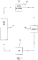
- FIGURE 1 describes the components of the climate control system.
- FIGURES 2A through 2C describe the configuration of the metal rack for mounting compressors.
- FIGURE 3 describes a method of arranging the metal rack.
- FIGURE 1 illustrates an example climate control system 100.
- system 100 includes a high side heat exchanger 105, a flash tank 110, a load 115, and a compressor 120.
- the components of system 100 cycle a refrigerant through system 100 to cool a space.
- High side heat exchanger 105 removes heat from the refrigerant. When heat is removed from the refrigerant, the refrigerant is cooled. This disclosure contemplates high side heat exchanger 105 being operated as a condenser and/or a gas cooler. When operating as a condenser, high side heat exchanger 105 cools the refrigerant such that the state of the refrigerant changes from a gas to a liquid. When operating as a gas cooler, high side heat exchanger 105 cools the refrigerant but the refrigerant remains a gas. In certain configurations, high side heat exchanger 105 is positioned such that heat removed from the refrigerant may be discharged into the air.
- high side heat exchanger 105 may be positioned on a rooftop so that heat removed from the refrigerant may be discharged into the air.
- high side heat exchanger 105 may be positioned external to a building and/or on the side of a building.
- Flash tank 110 stores refrigerant received from high side heat exchanger 105.
- This disclosure contemplates flash tank 110 storing refrigerant in any state such as, for example, a liquid state and/or a gaseous state. Refrigerant leaving flash tank 110 is fed to load 115.
- This disclosure contemplates system 100 including any number of flash tanks 110. Flash tank 110 is referred to as a receiving vessel in certain embodiments.
- Load 115 receives the refrigerant from flash tank 110. Load 115 cycles the refrigerant to cool a space proximate load 115. For example, load 115 may use the refrigerant to cool air proximate load 115. Then load 115 may circulate the cooled air using a fan to cool a larger space.
- Compressor 120 compresses refrigerant received from load 115.
- This disclosure contemplates system 100 including any number of compressors 120.
- Compressor 120 may be configured to increase the pressure of the refrigerant. As a result, the heat in the refrigerant may become concentrated and the refrigerant may become a high pressure gas.
- Compressor 120 may send the compressed refrigerant to high side heat exchanger 105.
- climate control system 100 may include one or more high side heat exchangers 105, flash tanks 110, loads 115, and/or compressors 120. climate control system 100 may also include piping that controls the flow of the refrigerant through system 100. climate control system 100 may further include other components typically found in a climate control system such as, for example, a filter dryer, an oil separator, and an accumulator. This disclosure contemplates climate control system 100 including any appropriate component.
- FIGURES 2A through 2C illustrate climate control system 100 arranged in a modular metal rack.
- components of climate control system 100 may be modified and/or replaced without having to remanufacture the entire metal rack.
- the modular metal rack may be expanded without having to remanufacture the entire metal rack.
- additional compressors 120 may be added to the metal rack without having to remanufacture the entire metal rack.
- FIGURE 2A illustrates a frontal view of the example climate control system 100 of FIGURE 1 arranged in a modular rack 200.
- climate control system 100 includes flash tank 110, compressors 120, and high side heat exchanger 105.
- Compressors 120 are located in their own section of rack 200.
- components of system 100 may be modified and/or replaced without having to remanufacture rack 200.
- the section of rack 200 containing compressors 120 can be expanded to accommodate additional compressors 120 without having to remanufacture the entire rack 200.
- compressors 120 may be added to climate control system 100.
- the additional compressors may be chained together with the original compressor 120. In this manner, the additional compressors 120 may further compress the refrigerant from the original compressor 120.
- the additional compressors 120 may send the compressed refrigerant to high side heat exchanger 105.
- the portion of rack 200 for compressors 120 may be expanded to accommodate the additional compressors.
- Each of these compressors 120 and the original compressor 120 may be arranged such that they are each accessible and removable through the front of rack 200.
- This disclosure contemplates high side heat exchanger 105 coupling, through piping, to a heat removal unit.
- the heat removal unit may further remove heat from the refrigerant in system 100.
- the heat removal unit may be located on the exterior of a building or on the ceiling of the building.
- the heat removal unit may discharge any removed heat into the air outside the building.
- the heat removal unit may then send the refrigerant to flash tank 110.
- climate control system 100 may include additional components such as a filter dryer, an oil separator, and an accumulator.
- the filter dryer may be arranged in space 296 such that the filter dryer is accessible and removable through planar boundary 290.
- the filter dryer may also be arranged in space 294 such that the filter dryer is accessible and removable through planar boundary 270.
- the oil separator may be coupled to one or more compressors 120, and the accumulator may be coupled to one or more compressors 120. Both the oil separator and the accumulator may be contained entirely within space 294.
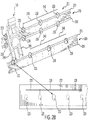
- FIGURE 2B illustrates a portion of the rack 200 of FIGURE 2A for mounting compressors 120.
- rack 200 includes metal beams 205 and 210.
- Metal beams 205 and 210 are customized to allow compressor mounting.
- Metal beams 205 and 210 each include a top surface 215 and a bottom surface 220. Each of the top surface 215 and the bottom surface 220 may define multiple cavities 225 and 230 used to mount compressors 120. As illustrated in FIGURE 2B , cavities 225 and cavities 230 may be of different shapes. For example, cavities 225 may be circles while cavities 230 are hexagons. Each of the cavities 225 and 230 may be separated by a distance 235. Distance 235 may be substantially the same between all cavities 225 and 230.
- Each cavity 230 may be separated from another cavity 230 by a distance 240.
- Distance 240 is greater than distance 235.
- Each of distances 240 may be substantially the same. Separating each cavity 230 from another cavity 230 by distance 240 may ensure that there is sufficient space to between mounted compressors 120.
- cavities 225 and 230 delineate the positions on metal beams 205 and 210 on which compressors 120 are to be mounted.
- cavities 230 may mark a spot where compressor 120 is to be mounted.
- Mounting compressors 120 only at cavities 230 may ensure that there is enough space to mount additional compressors of different sizes and/or from different manufacturers.
- mounting compressors only at cavities 230 may ensure that there is enough space between compressors 120 to access and/or remove each compressor 120.
- cavities 230 are referred to as mounting cavities.
- this disclosure describes mounting compressors only at cavities 230, this disclosure contemplates that the mounting of compressors 120 still involve cavities 225.
- Cavities 230 are simply reference points from which mounting the compressors 120 takes place. As illustrated in FIGURE 2B , mounting compressor 120 involves cavities 230 and cavities 225.
- the cavities defined by top surfaces 215 of metal beams 205 and 210 may line up with the cavities defined by bottom surfaces 220 of metal beams 205 and 210.
- the cavities 225 and 230 along top surface 215 may correspond to cavities 225 and 230 along bottom surface 220.
- each cavity 225 along top surface 215 may correspond to another cavity 225 along bottom surface 220
- each cavity 230 along top surface 215 may correspond to another cavity 230 along bottom surface 220.
- a line defined by a cavity 225 or 230 and its corresponding cavity 225 and 230 may be orthogonal to the linearly horizontal arrangement of metal beams 205 and 210.
- Compressors 120 may be mounted to metal beams 205 and 210 through mounting brackets 245. Each mounting bracket 245 may couple to compressor 120 and a top surface 215 of metal beams 205 and 210. In particular embodiments, mounting brackets 245 are designed to couple to metal beams 205 and 210 at cavities 225 and 230. Cavities 230 may be used as reference points from which mounting brackets 245 may be coupled to metal beams 205 and 210. Mounting compressors 120 only at cavities 230 may ensure that there is sufficient space between compressors 120 mounted on metal beams 205 and 210.
- particular fastening devices are used to couple mounting brackets 245 to cavities 225 and 230 of metal beams 205 and 210.
- the fastening devices may be screws or bolts configured to fit a hex cavity 230.
- the fastening devices may also be screws or bolts configured to fit a circular cavity 225.
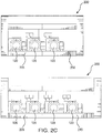
- FIGURE 2C illustrates a portion of the rack 200 of FIGURE 2A for mounting compressors 120.
- compressors 120 may be mounted on metal beams 205 and 250.
- the section of rack 200 for compressors 120 may be expanded to accommodate any number of compressors 120.
- Metal beam 205 may be coupled to metal beam 250 to expand the amount of space available to mount compressors 120.
- metal beam 250 is longer than metal beam 205.
- Metal beam 205 may be coupled to metal beam 250 in an appropriate manner.
- metal beams 205 and 250 may include fastening devices that allow metal beam 205 to couple to metal beam 250.
- Metal beam 250 may define cavities 225 and cavities 230 in the same manner as metal beam 205, described above using FIGURE 2B .
- metal beams 205 and 250 may be configured such that they couple together without affecting the distances 235 and 240 between the cavities of metal beams 205 and 250. For example, after metal beams 205 and 250 are coupled together the right most cavity 225 or 230 of metal beam 205 and the left most cavity 225 or 230 of metal beam 250 may be separated by distance 235. As another example, after metal beams 205 and 250 are coupled together, the right most cavity 230 of metal beam 205 may be separated from the left most cavity 230 of metal beam 250 by distance 240. In this manner, after metal beams 205 and 250 are coupled together they may be visualized as one metal beam of rack 200.
- Metal beam 250 may be any appropriate length to accommodate additional compressors 120. As illustrated in FIGURE 2C , metal beam 250 may be of a length to accommodate one compressor 120 and/or two compressors 120. This disclosure contemplates metal beam 250 being of a length to accommodate any number of compressors 120. In particular embodiments, using metal beam 250 to expand rack 200 allows for compressors 120 to be added to rack 200 without having to remanufacture the entire rack 200. As with metal beam 205, compressors 120 may be mounted to metal beam 250 only at cavities 230 of metal beam 250. In this manner, sufficient space between compressors 120 may be ensured.
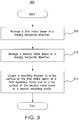
- FIGURE 3 is a flowchart illustrating a method 300 of mounting a compressor to the rack of FIGURE 2A .
- Method 300 may be performed by a person and/or a machine arranging rack 200.
- additional compressors may be added to the rack without having to remanufacture the entire rack.
- step 305 the person or machine arranges a first metal beam in a linearly horizontal direction.
- step 310 the person or machine arranges a second metal beam in a linearly horizontal direction.
- These two horizontal beams may each define certain cavities on which compressors may be mounted. Some of these cavities may have a different shape from the other cavities. The compressors may be mounted at the different shaped cavities.
- the person or machine couples a mounting bracket to a top surface of the first metal beam at a first mounting cavity and to a top surface of the second metal beam at a second mounting cavity.
- the first and second mounting cavities may have different shapes from other cavities along the top surfaces of the first metal beam and the second metal beam.
- mounting compressors only add the mounting cavities of the first and second metal beams may ensure that there is sufficient space between the compressors of the rack.
- Method 300 may include more, fewer, or other steps. For example, steps may be performed in parallel or in any suitable order.
Landscapes
- Engineering & Computer Science (AREA)
- General Engineering & Computer Science (AREA)
- Mechanical Engineering (AREA)
- Chemical & Material Sciences (AREA)
- Combustion & Propulsion (AREA)
- Compressor (AREA)
- Structures Of Non-Positive Displacement Pumps (AREA)
- Physics & Mathematics (AREA)
- Thermal Sciences (AREA)
- Life Sciences & Earth Sciences (AREA)
- Sustainable Development (AREA)
- Compressors, Vaccum Pumps And Other Relevant Systems (AREA)
Description
- This disclosure relates generally to a rack for a climate control system, specifically a rack for compressor mounting.
- Climate control systems are often arranged on metal racks. For example, a metal rack can be configured to accommodate a high side heat exchanger, a flash tank, a compressor, etc. The racks can be manufactured in various sizes to accommodate any number of components of the climate control systems.
-
CN203005018U describes a support for an automobile-used conditioner compressor, which comprises a support body, wherein four bosses are arranged on the back of the support body; a compressor mounting hole is formed in each boss; four generator access holes are formed in front of the support body; the heights of the bosses are different, the heights of a first boss and a second boss are the same, and the heights of a third boss and a fourth boss are the same and lower than those of the first boss and the second boss; two catches and an L-shaped bulged piece are connected to the lateral surface of the support body; a through groove is formed in the side wall of the bulged piece; a reinforcing rib is arranged in front of the support body, and a plurality of grooves are further formed in the back; and the support body, the four bosses, the bulged piece, the reinforcing rid and two catches are all-in-one aluminum alloy castings. - According to one example implementation, an apparatus includes a first metal beam, a second metal beam, and a mounting bracket. The first and second metal beams are arranged in a linearly horizontal direction. The first metal beam defines a plurality of first and second cavities along a top surface of the first metal beam. Each first cavity is of a first shape and is separated from another first cavity by a first distance. Each second cavity is of a second shape different from the first shape and is separated from another second cavity by a second distance greater than the first distance. The second metal beam defines a plurality of third and fourth cavities along a top surface of the second metal beam. Each third cavity is of the first shape and is separated from another third cavity by the first distance. Each fourth cavity is of the second shape and is separated from another fourth cavity by the second distance. The mounting bracket couples to the top surface of the first metal beam at a first mounting cavity of the plurality of second cavities and the top surface of the second metal beam at a second mounting cavity of the plurality of fourth cavities. The mounting bracket further couples to a compressor.
- According to an embodiment, a method in accordance with claim 1 is disclosed.
- According to another embodiment, an apparatus includes a first metal beam and a mounting bracket in accordance with
claim 7. - Certain embodiments may provide one or more technical advantages. For example, an embodiment allows for compressors of various sizes, types, and/or manufacturers to be mounted to a rack. As another example, an embodiment allows for a rack to be expanded to accommodate additional compressors. Certain embodiments may include none, some, or all of the above technical advantages. One or more other technical advantages may be readily apparent to one skilled in the art from the figures, descriptions, and claims included herein.
- For a more complete understanding of the present disclosure, reference is now made to the following description, taken in conjunction with the accompanying drawings, in which:
-
FIGURE 1 illustrates an example climate control system; -
FIGURE 2A illustrates a frontal view of the example climate control system ofFIGURE 1 arranged in a rack; -
FIGURE 2B illustrates a portion of the rack ofFIGURE 2A for mounting compressors; -
FIGURE 2C illustrates a portion of the rack ofFIGURE 2A for mounting compressors; -
FIGURE 3 is a flowchart illustrating a method of mounting a compressor to the rack ofFIGURE 2A . - Embodiments of the present disclosure and its advantages are best understood by referring to
FIGURES 1 through 3 of the drawings, like numerals being used for like and corresponding parts of the various drawings. - Climate control systems are often arranged on metal racks. For example, a metal rack can be configured to accommodate a high side heat exchanger, a flash tank, a compressor and other various components of a climate control system. The rack can be manufactured in various sizes to accommodate any number of components of the climate control system. The components of the climate control system can then be mounted onto the metal rack. The metal rack can then be placed in a closet or room where the climate control system is stored.
- The metal rack is typically manufactured to accommodate the particular needs of a climate control system. For example, if a climate control system utilizes only two compressors, then the metal rack can be manufactured with enough space for two compressors. As another example, if a climate control system utilizes six compressors, then the metal rack can be manufactured with enough space to accommodate six compressors. As yet another example, if a climate control system utilizes two flash tanks, then the rack can be manufactured to accommodate two flash tanks. Therefore, the metal racks can be manufactured to suit the needs of any climate control system.
- This type of manufacture of metal racks presents a challenge when the climate control system needs to be modified. In such instances, the manufactured rack may no longer be suitable for the modified climate control system. As a result, a new rack may need to be manufactured to accommodate the modified climate control system. For example, if compressors need to be added to an existing climate control system, the metal rack for that climate control system may not be large enough to accommodate the additional compressors. As a result, a new, larger rack may need to be manufactured to accommodate the modified climate control system.
- This disclosure contemplates a climate control system arranged in a modular metal rack that allows for portions of the climate control system to be modified without having to remanufacture the entire metal rack. Specifically, the metal rack sections off the portion of the climate control system that utilizes compressors. That section of the metal rack can be expanded and/or modified without affecting the configuration of the other sections of the metal rack. In this manner, the metal rack can be modified to accommodate additional compressors without having to remanufacture the entire rack.
- Furthermore, the metal beams used to mount compressors to the rack include two types of holes, one type being of a different shape than the other type. The differently shaped holes can be used to mark the location on the metal beams where compressors should be mounted. Enough space can be provided between the differently shaped holes to ensure that there is sufficient space between mounted compressors. In this manner, compressors of various sizes or various manufactures can be mounted to the metal beams without hindering the mounting of additional compressors. Moreover, the entire metal rack need not be remanufactured to accommodate compressors of different sizes or manufactures.
- In particular embodiments, by using the metal rack, compressors can be added to the system without affecting certain portions of the rack. In some embodiments, the rack allows for compressors to be added to the climate control system without needing a new metal rack to be manufactured. The climate control system will be discussed in more detail using
FIGURES 1 through 3 .FIGURE 1 describes the components of the climate control system.FIGURES 2A through 2C describe the configuration of the metal rack for mounting compressors.FIGURE 3 describes a method of arranging the metal rack. -
FIGURE 1 illustrates an exampleclimate control system 100. As illustrated inFIGURE 1 ,system 100 includes a highside heat exchanger 105, aflash tank 110, aload 115, and acompressor 120. The components ofsystem 100 cycle a refrigerant throughsystem 100 to cool a space. - High
side heat exchanger 105 removes heat from the refrigerant. When heat is removed from the refrigerant, the refrigerant is cooled. This disclosure contemplates highside heat exchanger 105 being operated as a condenser and/or a gas cooler. When operating as a condenser, highside heat exchanger 105 cools the refrigerant such that the state of the refrigerant changes from a gas to a liquid. When operating as a gas cooler, highside heat exchanger 105 cools the refrigerant but the refrigerant remains a gas. In certain configurations, highside heat exchanger 105 is positioned such that heat removed from the refrigerant may be discharged into the air. For example, highside heat exchanger 105 may be positioned on a rooftop so that heat removed from the refrigerant may be discharged into the air. As another example, highside heat exchanger 105 may be positioned external to a building and/or on the side of a building. -
Flash tank 110 stores refrigerant received from highside heat exchanger 105. This disclosure contemplatesflash tank 110 storing refrigerant in any state such as, for example, a liquid state and/or a gaseous state. Refrigerant leavingflash tank 110 is fed to load 115. This disclosure contemplatessystem 100 including any number offlash tanks 110.Flash tank 110 is referred to as a receiving vessel in certain embodiments. -
Load 115 receives the refrigerant fromflash tank 110.Load 115 cycles the refrigerant to cool a spaceproximate load 115. For example, load 115 may use the refrigerant to cool airproximate load 115. Then load 115 may circulate the cooled air using a fan to cool a larger space. -
Compressor 120 compresses refrigerant received fromload 115. This disclosure contemplatessystem 100 including any number ofcompressors 120.Compressor 120 may be configured to increase the pressure of the refrigerant. As a result, the heat in the refrigerant may become concentrated and the refrigerant may become a high pressure gas.Compressor 120 may send the compressed refrigerant to highside heat exchanger 105. - This disclosure contemplates
climate control system 100 including any number of components. For example,climate control system 100 may include one or more highside heat exchangers 105,flash tanks 110, loads 115, and/orcompressors 120.Climate control system 100 may also include piping that controls the flow of the refrigerant throughsystem 100.Climate control system 100 may further include other components typically found in a climate control system such as, for example, a filter dryer, an oil separator, and an accumulator. This disclosure contemplatesclimate control system 100 including any appropriate component. -
FIGURES 2A through 2C illustrateclimate control system 100 arranged in a modular metal rack. By arrangingclimate control system 100 in a modular metal rack, components ofclimate control system 100 may be modified and/or replaced without having to remanufacture the entire metal rack. Furthermore, the modular metal rack may be expanded without having to remanufacture the entire metal rack. For example,additional compressors 120 may be added to the metal rack without having to remanufacture the entire metal rack. -
FIGURE 2A illustrates a frontal view of the exampleclimate control system 100 ofFIGURE 1 arranged in amodular rack 200. As illustrated inFIGURE 2A ,climate control system 100 includesflash tank 110,compressors 120, and highside heat exchanger 105.Compressors 120 are located in their own section ofrack 200. By arrangingclimate control system 100 inrack 200, components ofsystem 100 may be modified and/or replaced without having to remanufacturerack 200. For example, the section ofrack 200 containingcompressors 120 can be expanded to accommodateadditional compressors 120 without having to remanufacture theentire rack 200. - In some embodiments,
compressors 120 may be added toclimate control system 100. The additional compressors may be chained together with theoriginal compressor 120. In this manner, theadditional compressors 120 may further compress the refrigerant from theoriginal compressor 120. Theadditional compressors 120 may send the compressed refrigerant to highside heat exchanger 105. The portion ofrack 200 forcompressors 120 may be expanded to accommodate the additional compressors. Each of thesecompressors 120 and theoriginal compressor 120 may be arranged such that they are each accessible and removable through the front ofrack 200. - This disclosure contemplates high
side heat exchanger 105 coupling, through piping, to a heat removal unit. The heat removal unit may further remove heat from the refrigerant insystem 100. The heat removal unit may be located on the exterior of a building or on the ceiling of the building. The heat removal unit may discharge any removed heat into the air outside the building. The heat removal unit may then send the refrigerant toflash tank 110. - In particular embodiments,
climate control system 100 may include additional components such as a filter dryer, an oil separator, and an accumulator. The filter dryer may be arranged in space 296 such that the filter dryer is accessible and removable through planar boundary 290. The filter dryer may also be arranged in space 294 such that the filter dryer is accessible and removable through planar boundary 270. The oil separator may be coupled to one ormore compressors 120, and the accumulator may be coupled to one ormore compressors 120. Both the oil separator and the accumulator may be contained entirely within space 294. -
FIGURE 2B illustrates a portion of therack 200 ofFIGURE 2A for mountingcompressors 120. As illustrated inFIGURE 2B ,rack 200 includesmetal beams - Metal beams 205 and 210 each include a
top surface 215 and abottom surface 220. Each of thetop surface 215 and thebottom surface 220 may definemultiple cavities compressors 120. As illustrated inFIGURE 2B ,cavities 225 andcavities 230 may be of different shapes. For example,cavities 225 may be circles whilecavities 230 are hexagons. Each of thecavities distance 235.Distance 235 may be substantially the same between allcavities - Each
cavity 230 may be separated from anothercavity 230 by adistance 240.Distance 240 is greater thandistance 235. Each ofdistances 240 may be substantially the same. Separating eachcavity 230 from anothercavity 230 bydistance 240 may ensure that there is sufficient space to betweenmounted compressors 120. - In particular embodiments, the different shapes of
cavities metal beams compressors 120 are to be mounted. For example,cavities 230 may mark a spot wherecompressor 120 is to be mounted. Mountingcompressors 120 only atcavities 230 may ensure that there is enough space to mount additional compressors of different sizes and/or from different manufacturers. Furthermore, mounting compressors only atcavities 230 may ensure that there is enough space betweencompressors 120 to access and/or remove eachcompressor 120. In certain embodiments,cavities 230 are referred to as mounting cavities. Although this disclosure describes mounting compressors only atcavities 230, this disclosure contemplates that the mounting ofcompressors 120 still involvecavities 225.Cavities 230 are simply reference points from which mounting thecompressors 120 takes place. As illustrated inFIGURE 2B , mountingcompressor 120 involvescavities 230 andcavities 225. - In particular embodiments, the cavities defined by
top surfaces 215 ofmetal beams bottom surfaces 220 ofmetal beams cavities top surface 215 may correspond tocavities bottom surface 220. For example, eachcavity 225 alongtop surface 215 may correspond to anothercavity 225 alongbottom surface 220, and eachcavity 230 alongtop surface 215 may correspond to anothercavity 230 alongbottom surface 220. In this manner, a line defined by acavity corresponding cavity metal beams -
Compressors 120 may be mounted tometal beams brackets 245. Each mountingbracket 245 may couple tocompressor 120 and atop surface 215 ofmetal beams brackets 245 are designed to couple tometal beams cavities Cavities 230 may be used as reference points from which mountingbrackets 245 may be coupled tometal beams compressors 120 only atcavities 230 may ensure that there is sufficient space betweencompressors 120 mounted onmetal beams - In particular embodiments, particular fastening devices are used to couple mounting
brackets 245 tocavities metal beams FIGURE 2B , the fastening devices may be screws or bolts configured to fit ahex cavity 230. The fastening devices may also be screws or bolts configured to fit acircular cavity 225. -
FIGURE 2C illustrates a portion of therack 200 ofFIGURE 2A for mountingcompressors 120. As illustrated inFIGURE 2C ,compressors 120 may be mounted onmetal beams metal beams rack 200 forcompressors 120 may be expanded to accommodate any number ofcompressors 120. -
Metal beam 205 may be coupled tometal beam 250 to expand the amount of space available to mountcompressors 120. In particular embodiments,metal beam 250 is longer thanmetal beam 205.Metal beam 205 may be coupled tometal beam 250 in an appropriate manner. For example,metal beams metal beam 205 to couple tometal beam 250.Metal beam 250 may definecavities 225 andcavities 230 in the same manner asmetal beam 205, described above usingFIGURE 2B . - In certain embodiments,
metal beams distances metal beams metal beams most cavity metal beam 205 and the leftmost cavity metal beam 250 may be separated bydistance 235. As another example, aftermetal beams most cavity 230 ofmetal beam 205 may be separated from the leftmost cavity 230 ofmetal beam 250 bydistance 240. In this manner, aftermetal beams rack 200. -
Metal beam 250 may be any appropriate length to accommodateadditional compressors 120. As illustrated inFIGURE 2C ,metal beam 250 may be of a length to accommodate onecompressor 120 and/or twocompressors 120. This disclosure contemplatesmetal beam 250 being of a length to accommodate any number ofcompressors 120. In particular embodiments, usingmetal beam 250 to expandrack 200 allows forcompressors 120 to be added to rack 200 without having to remanufacture theentire rack 200. As withmetal beam 205,compressors 120 may be mounted tometal beam 250 only atcavities 230 ofmetal beam 250. In this manner, sufficient space betweencompressors 120 may be ensured. -
FIGURE 3 is a flowchart illustrating amethod 300 of mounting a compressor to the rack ofFIGURE 2A .Method 300 may be performed by a person and/or amachine arranging rack 200. In particular embodiments, by performingmethod 300 additional compressors may be added to the rack without having to remanufacture the entire rack. - In
step 305, the person or machine arranges a first metal beam in a linearly horizontal direction. Instep 310, the person or machine arranges a second metal beam in a linearly horizontal direction. These two horizontal beams may each define certain cavities on which compressors may be mounted. Some of these cavities may have a different shape from the other cavities. The compressors may be mounted at the different shaped cavities. - In
step 315, the person or machine couples a mounting bracket to a top surface of the first metal beam at a first mounting cavity and to a top surface of the second metal beam at a second mounting cavity. The first and second mounting cavities may have different shapes from other cavities along the top surfaces of the first metal beam and the second metal beam. In particular embodiments, mounting compressors only add the mounting cavities of the first and second metal beams may ensure that there is sufficient space between the compressors of the rack. - Modifications, additions, or omissions may be made to
method 300 depicted inFIGURE 3 .Method 300 may include more, fewer, or other steps. For example, steps may be performed in parallel or in any suitable order. - Although the present disclosure includes several embodiments, a myriad of changes, variations, alterations, transformations, and modifications may be suggested to one skilled in the art, and it is intended that the present disclosure encompass such changes, variations, alterations, transformations, and modifications as fall within the scope of the appended claims.
Claims (18)
- A method comprising:arranging a first metal beam (205) in a linearly horizontal direction, the first metal beam (205) defining:a plurality of first cavities (225) along a top surface (215) of the first metal beam (205), each first cavity (225) being of a first shape, each first cavity (225) separated from another first cavity (225) by a first distance (235);a plurality of second cavities (230) along the top surface (215) of the first metal beam (205), each second cavity (230) being of a second shape different from the first shape, each second cavity (230) separated from another second cavity (230) by a second distance (240) greater than the first distance (235);a plurality of fifth cavities (225) along a bottom surface (220) of the first metal beam (205), each fifth cavity (225) being of the first shape, each fifth cavity (225) separated from another fifth cavity (225) by the first distance (235), each fifth cavity (225) defining with a first cavity (225) a first line orthogonal to the linearly horizontal direction; anda plurality of sixth cavities (230) along the bottom surface (220) of the first metal beam (205), each sixth cavity (230) being of the second shape, each sixth cavity (230) separated from another sixth cavity (230) by the second distance (240), each sixth cavity (230) defining with a second cavity (230) a second line orthogonal to the linearly horizontal direction;arranging a second metal beam (210) in a linearly horizontal direction, the second metal beam (210) defining:a plurality of third cavities (225) along a top surface (215) of the second metal beam (210), each third cavity (225) being of the first shape, each third cavity (225) separated from another third cavity (225) by the first distance (235); anda plurality of fourth cavities (230) along the top surface (215) of the second metal beam (210), each fourth cavity (230) being of the second shape, each fourth cavity (230) separated from another fourth cavity (230) by the second distance (240); andcoupling a mounting bracket (245) to the top surface (215) of the first metal beam (205) at a first mounting cavity (230) of the plurality of second cavities (230) and the top surface (215) of the second metal beam (210) at a second mounting cavity (230) of the plurality of fourth cavities (230), the mounting bracket (245) configured to further couple to a compressor (120).
- The method of Claim 1, further comprising a second mounting bracket (245) configured to couple to the top surface (215) of the first metal beam (205) at a third mounting cavity (230) of the plurality of second cavities (230) and the top surface (215) of the second metal beam (210) at a fourth mounting cavity (230) of the plurality of fourth cavities (230), the third mounting cavity (230) separated from the first mounting cavity (230) by the second distance (240), the fourth mounting cavity (230) separated from the second mounting cavity (230) by the second distance (240), the second mounting bracket (245) configured to further couple to a second compressor (120).
- The method of Claim 1 or Claim 2, wherein the first metal beam (205) is configured to further couple to a third metal beam (250), the third metal beam (250) defining a plurality of seventh cavities (225) along a top surface (215) of the third metal beam (250) and a plurality of eighth cavities (230) along the top surface (215) of the third metal beam (250), wherein:each seventh cavity (225) being of the first shape, each seventh cavity (225) is separated from another seventh cavity (225) by the first distance (235);each eighth cavity (230) being of the second shape, each eighth cavity (230) is separated from another eighth cavity (230) by the second distance (240); andan eighth cavity (230) of the plurality of eighth cavities (230) is separated from a second cavity (230) of the plurality of second cavities (230) by the second distance (240) when the third metal beam (250) is coupled to the first metal beam (205).
- The method of Claim 3, wherein a second mounting bracket (245) is configured to couple to the third metal beam (250) at a third mounting cavity (230) of the plurality of eighth cavities (230), the second mounting bracket (245) further configured to couple to a second compressor (120).
- The method of Claim 3 or of Claim 4, wherein the third metal beam (250) is longer than the first metal beam (205).
- The method of Claim 1 or any preceding method claim, wherein the first shape is a circle and the second shape is a hexagon.
- An apparatus (200) comprising:a first metal beam (205) arranged in a linearly horizontal direction, the first metal beam (205) defining:a plurality of first cavities (225) along a top surface (215) of the first metal beam (205), each first cavity (225) being of a first shape, each first cavity (225) separated from another first cavity (225) by a first distance (235);a plurality of second cavities (230) along the top surface (215) of the first metal beam (205), each second cavity (230) being of a second shape different from the first shape, each second cavity (230) separated from another second cavity (230) by a second distance (240) greater than the first distance (245);a plurality of fifth cavities (225) along a bottom surface (220) of the first metal beam (205), each fifth cavity (225) being of the first shape, each fifth cavity (225) separated from another fifth cavity (225) by the first distance (235), each fifth cavity (225) defining with a first cavity (225) a first line orthogonal to the linearly horizontal direction; anda plurality of sixth cavities (230) along the bottom surface (220) of the first metal beam (205), each sixth cavity (230) being of the second shape, each sixth cavity (230) separated from another sixth cavity (230) by the second distance (240), each sixth cavity (230) defining with a second cavity (230) a second line orthogonal to the linearly horizontal direction; anda mounting bracket (245) configured to couple to the top surface (215) of the first metal beam (205) at a first mounting cavity (230) of the plurality of second cavities (230), the mounting bracket (245) configured to further couple to a compressor (120).
- The apparatus (200) of Claim 7, further comprising a second mounting bracket (245) configured to couple to the top surface (215) of the first metal beam (205) at a third mounting cavity (230) of the plurality of second cavities (230), the third mounting cavity (230) separated from the first mounting cavity (230) by the second distance (240), the second mounting bracket (245) configured to further couple to a second compressor (120).
- The apparatus (200) of Claim 7 or of Claim 8, wherein the first metal beam (205) is configured to further couple to a second metal beam (210), the second metal beam (210) defining a plurality of third cavities (225) along a top surface (215) of the second metal beam (210) and a plurality of fourth cavities (230) along the top surface (215) of the second metal beam (210), wherein:each third cavity (225) being of the first shape, each third cavity (225) is separated from another third cavity (225) by the first distance (235);each fourth cavity (230) being of the second shape, each fourth cavity (230) is separated from another fourth cavity (230) by the second distance (240); anda fourth cavity (230) of the plurality of fourth cavities (230) is separated from a second cavity (230) of the plurality of second cavities (230) by the second distance (240) when the second metal beam (210) is coupled to the first metal beam (205).
- The apparatus (200) of Claim 9, wherein a second mounting bracket (245) is configured to couple to the second metal beam (210) at a third mounting cavity (230) of the plurality of fourth cavities (230), the second mounting bracket (245) further configured to couple to a second compressor (120).
- The apparatus (200) of Claim 9 or of Claim 10, wherein the second metal beam (210) is longer than the first metal beam (205).
- The apparatus (200) of Claim 7 or of any of Claims 8 to 11, wherein the first shape is a circle and the second shape is a hexagon.
- The apparatus (200) of Claim 7 or of any of Claims 8 to 12, further comprising:a second metal beam (210) arranged in a linearly horizontal direction, the second metal beam (210) defining:a plurality of third cavities (225) along a top surface (215) of the second metal beam (210), each third cavity (225) being of the first shape, each third cavity (225) separated from another third cavity (225) by the first distance (235); anda plurality of fourth cavities (230) along the top surface (215) of the second metal beam (210), each fourth cavity (230) being of the second shape, each fourth cavity (230) separated from another fourth cavity (230) by the second distance (240);wherein the mounting bracket (245) is further configured to couple to the top surface (215) of the second metal beam (210) at a second mounting cavity (230) of the plurality of fourth cavities (230).
- The apparatus (200) of claim 13, further comprising a second mounting bracket (245) configured to couple to the top surface (215) of the first metal beam (205) at a third mounting cavity (230) of the plurality of second cavities (230) and the top surface (215) of the second metal beam (210) at a fourth mounting cavity (230) of the plurality of fourth cavities (230), the third mounting cavity (230) separated from the first mounting cavity (230) by the second distance (240), the fourth mounting cavity (230) separated from the second mounting cavity (230) by the second distance (240), the second mounting bracket (240) configured to further couple to a second compressor (120).
- The apparatus (200) of Claim 13 or Claim 14, wherein the first metal beam (205) is configured to further couple to a third metal beam (250), the third metal beam (250) defining a plurality of seventh cavities (225) along a top surface (215) of the third metal beam (250) and a plurality of eighth cavities (230) along the top surface (215) of the third metal beam (250), wherein:each seventh cavity (225) being of the first shape, each seventh cavity (225) is separated from another seventh cavity (225) by the first distance (235);each eighth cavity (230) being of the second shape, each eighth cavity (230) is separated from another eighth cavity (230) by the second distance (240); andan eighth cavity (230) of the plurality of eighth cavities (230) is separated from a second cavity (230) of the plurality of second cavities (230) by the second distance (240) when the third metal beam (250) is coupled to the first metal beam (205).
- The apparatus (200) of Claim 15, wherein a second mounting bracket (245) is configured to couple to the third metal beam (250) at a third mounting cavity (230) of the plurality of eighth cavities (230), the second mounting bracket (245) further configured to couple to a second compressor (120).
- The apparatus (200) of Claim 15 or Claim 16, wherein the third metal beam (250) is longer than the first metal beam (205).
- The apparatus (200) of Claim 13 or of any of Claims 14 to 17, wherein the first shape is a circle and the second shape is a hexagon.
Applications Claiming Priority (1)
| Application Number | Priority Date | Filing Date | Title |
|---|---|---|---|
| US15/053,206 US10180266B2 (en) | 2016-02-25 | 2016-02-25 | Expansion rack for compressor mounting |
Publications (2)
| Publication Number | Publication Date |
|---|---|
| EP3225933A1 EP3225933A1 (en) | 2017-10-04 |
| EP3225933B1 true EP3225933B1 (en) | 2019-08-21 |
Family
ID=58231373
Family Applications (1)
| Application Number | Title | Priority Date | Filing Date |
|---|---|---|---|
| EP17157975.8A Active EP3225933B1 (en) | 2016-02-25 | 2017-02-24 | Expansion rack for compressor mounting |
Country Status (6)
| Country | Link |
|---|---|
| US (1) | US10180266B2 (en) |
| EP (1) | EP3225933B1 (en) |
| CN (1) | CN107120255B (en) |
| AU (1) | AU2017201299A1 (en) |
| BR (1) | BR102017004128A2 (en) |
| CA (1) | CA2958972C (en) |
Families Citing this family (3)
| Publication number | Priority date | Publication date | Assignee | Title |
|---|---|---|---|---|
| JP6269717B2 (en) * | 2016-04-21 | 2018-01-31 | ダイキン工業株式会社 | Heat source unit |
| US10465923B2 (en) * | 2017-12-26 | 2019-11-05 | Lennox Industries Inc. | Support system and methods for HVAC systems |
| CN111780268B (en) * | 2020-08-10 | 2024-08-13 | 无锡太湖学院 | Movable clamping device and air conditioner external unit mounting platform |
Family Cites Families (34)
| Publication number | Priority date | Publication date | Assignee | Title |
|---|---|---|---|---|
| US1656810A (en) * | 1923-08-11 | 1928-01-17 | Zeppelin Luftschiffbau | Hollow girder for light structures |
| US2323153A (en) * | 1942-03-23 | 1943-06-29 | Turner E Pilson | Motor mount |
| US2660117A (en) * | 1948-02-03 | 1953-11-24 | Masson Seeley & Co Ltd | Work support |
| BE560485A (en) * | 1956-09-03 | |||
| US3321168A (en) * | 1965-07-12 | 1967-05-23 | Gen Electric | Internal base plate for instrument transformers |
| US3324524A (en) * | 1965-10-22 | 1967-06-13 | Internat Product Design & Res | Sheet metal kiln stilt |
| US3890755A (en) * | 1973-05-23 | 1975-06-24 | Masyc Ag | Construction set |
| US6740851B2 (en) * | 2002-09-27 | 2004-05-25 | Nordson Corporation | Quick connect hot melt unit |
| US5157883A (en) * | 1989-05-08 | 1992-10-27 | Allan Meyer | Metal frames |
| US5010709A (en) * | 1990-02-28 | 1991-04-30 | Felix Paz | Bendable channel construction element |
| CA2077429C (en) * | 1992-09-02 | 1999-03-30 | Ernest R. Bodnar | Roll formed metal member |
| JPH09823A (en) * | 1995-06-21 | 1997-01-07 | Mitsubishi Heavy Ind Ltd | Dehydrator |
| US5626231A (en) * | 1995-11-27 | 1997-05-06 | Agfa Division, Bayer Corp. | Crate and pallet assembly |
| JPH09236287A (en) * | 1996-02-28 | 1997-09-09 | O K Kizai Kk | Air conditioner outdoor unit mounting table device |
| JPH09250781A (en) | 1996-03-14 | 1997-09-22 | Matsushita Seiko Co Ltd | Compressor fixing device for air conditioner |
| US6095482A (en) * | 1998-09-14 | 2000-08-01 | Lucent Technologies, Inc. | Universal equipment mounting structure and method of using |
| US7042710B1 (en) | 2003-06-10 | 2006-05-09 | Garmin Ltd. | Mounting system for electronic components |
| CN100513918C (en) * | 2004-05-19 | 2009-07-15 | 乐金电子(天津)电器有限公司 | Air conditioner |
| CN101137784B (en) * | 2005-02-02 | 2011-10-12 | 吉尔宝有限公司 | Washing machine support structure |
| CA2608625C (en) * | 2006-05-18 | 2010-07-20 | Sur-Stud Structural Technology Inc. | Light steel structural members |
| EP1890091A3 (en) * | 2006-08-09 | 2009-04-08 | Moshe Lavi | Modular air conditioner support assembly |
| CN101295201B (en) * | 2007-04-26 | 2011-11-09 | 鸿富锦精密工业(深圳)有限公司 | Data memory frame work |
| JP2010025415A (en) | 2008-07-17 | 2010-02-04 | Daikin Ind Ltd | Connecting structure and air conditioner comprising the same |
| CN101876465B (en) * | 2009-04-30 | 2013-11-27 | 乐金电子(天津)电器有限公司 | Saddle-shaped window type air-conditioner |
| US7944692B2 (en) | 2009-06-12 | 2011-05-17 | American Power Conversion Corporation | Method and apparatus for installation and removal of overhead cooling equipment |
| US20110005257A1 (en) | 2009-07-09 | 2011-01-13 | Crow Terry K | Geothermal heat pump system having a downflow appliance cabinet |
| CN102791088A (en) * | 2011-05-20 | 2012-11-21 | 鸿富锦精密工业(深圳)有限公司 | Electronic device |
| CN202429537U (en) | 2012-01-09 | 2012-09-12 | 东莞市芙蓉化工有限公司 | A new type of chemical tank |
| CN202439537U (en) * | 2012-02-03 | 2012-09-19 | 合肥市顺达铸造有限公司 | Support platform of air condition compressor of automobile |
| CN103576798A (en) * | 2012-07-24 | 2014-02-12 | 鸿富锦精密工业(深圳)有限公司 | Fan fixing device |
| CN103593909A (en) * | 2012-08-17 | 2014-02-19 | 鸿富锦精密工业(武汉)有限公司 | Base of vending machine |
| CN203005018U (en) | 2012-11-20 | 2013-06-19 | 四川华威兄弟科技有限公司 | Support for automobile-used air conditioner compressor |
| DE102013112761A1 (en) | 2013-11-19 | 2015-05-21 | R. Stahl Schaltgeräte GmbH | Holding device for a housing and method for mounting the housing using the holding device |
| CN203857235U (en) | 2014-04-14 | 2014-10-01 | 潍柴动力股份有限公司 | Support |
-
2016
- 2016-02-25 US US15/053,206 patent/US10180266B2/en active Active
-
2017
- 2017-02-24 CA CA2958972A patent/CA2958972C/en active Active
- 2017-02-24 EP EP17157975.8A patent/EP3225933B1/en active Active
- 2017-02-26 AU AU2017201299A patent/AU2017201299A1/en not_active Abandoned
- 2017-02-27 CN CN201710227838.8A patent/CN107120255B/en not_active Expired - Fee Related
- 2017-03-01 BR BR102017004128-0A patent/BR102017004128A2/en not_active Application Discontinuation
Non-Patent Citations (1)
| Title |
|---|
| None * |
Also Published As
| Publication number | Publication date |
|---|---|
| CN107120255B (en) | 2019-09-24 |
| CN107120255A (en) | 2017-09-01 |
| US20170248342A1 (en) | 2017-08-31 |
| US10180266B2 (en) | 2019-01-15 |
| CA2958972A1 (en) | 2017-08-25 |
| BR102017004128A2 (en) | 2017-11-21 |
| AU2017201299A1 (en) | 2017-09-14 |
| CA2958972C (en) | 2019-09-17 |
| EP3225933A1 (en) | 2017-10-04 |
Similar Documents
| Publication | Publication Date | Title |
|---|---|---|
| EP2040008B1 (en) | Outdoor unit of air conditioner | |
| CA2960073C (en) | Modular rack for climate control system | |
| EP2063192A1 (en) | Outdoor unit of air conditioner with air cooled passage in electrical equipment box and heat pipe | |
| US10612858B2 (en) | Evaporator | |
| CA2958972C (en) | Expansion rack for compressor mounting | |
| CN103261819A (en) | Evaporator | |
| KR101533005B1 (en) | Air-conditioning control device of server rack with flexible cooling duct | |
| EP3348936B1 (en) | Outdoor machine | |
| JP2005076924A (en) | Support structure for liquid reservoir and outdoor unit of air conditioner having the same | |
| JP6333108B2 (en) | Air conditioner heat source side unit | |
| KR102058953B1 (en) | Outdoor unit | |
| JP2009085465A (en) | Outdoor unit of air conditioner | |
| EP3514457A1 (en) | Heat source unit | |
| EP3361186A1 (en) | Refrigeration cycle device | |
| CN106016797A (en) | Micro-modularized refrigeration device and cabinet | |
| CN203298404U (en) | Air conditioner outdoor unit and air conditioner with same | |
| JP2018141593A (en) | Air conditioner | |
| US10920998B2 (en) | Outdoor unit for air-conditioning apparatus | |
| JP6190737B2 (en) | Refrigerant flow path switching device for air conditioner | |
| CN211120149U (en) | Multi-connected host and multi-connected system | |
| JP2016080272A (en) | Refrigeration device | |
| JP2007093151A (en) | Air conditioner | |
| KR0131387Y1 (en) | A multi-changing system for alternation of airconditioner for a vehicle | |
| JP2006275325A (en) | Compressor unit | |
| KR200157833Y1 (en) | Evaporator Housing Structure |
Legal Events
| Date | Code | Title | Description |
|---|---|---|---|
| PUAI | Public reference made under article 153(3) epc to a published international application that has entered the european phase |
Free format text: ORIGINAL CODE: 0009012 |
|
| STAA | Information on the status of an ep patent application or granted ep patent |
Free format text: STATUS: THE APPLICATION HAS BEEN PUBLISHED |
|
| AK | Designated contracting states |
Kind code of ref document: A1 Designated state(s): AL AT BE BG CH CY CZ DE DK EE ES FI FR GB GR HR HU IE IS IT LI LT LU LV MC MK MT NL NO PL PT RO RS SE SI SK SM TR |
|
| AX | Request for extension of the european patent |
Extension state: BA ME |
|
| STAA | Information on the status of an ep patent application or granted ep patent |
Free format text: STATUS: REQUEST FOR EXAMINATION WAS MADE |
|
| 17P | Request for examination filed |
Effective date: 20180404 |
|
| RBV | Designated contracting states (corrected) |
Designated state(s): AL AT BE BG CH CY CZ DE DK EE ES FI FR GB GR HR HU IE IS IT LI LT LU LV MC MK MT NL NO PL PT RO RS SE SI SK SM TR |
|
| GRAP | Despatch of communication of intention to grant a patent |
Free format text: ORIGINAL CODE: EPIDOSNIGR1 |
|
| STAA | Information on the status of an ep patent application or granted ep patent |
Free format text: STATUS: GRANT OF PATENT IS INTENDED |
|
| INTG | Intention to grant announced |
Effective date: 20190318 |
|
| GRAS | Grant fee paid |
Free format text: ORIGINAL CODE: EPIDOSNIGR3 |
|
| GRAA | (expected) grant |
Free format text: ORIGINAL CODE: 0009210 |
|
| STAA | Information on the status of an ep patent application or granted ep patent |
Free format text: STATUS: THE PATENT HAS BEEN GRANTED |
|
| AK | Designated contracting states |
Kind code of ref document: B1 Designated state(s): AL AT BE BG CH CY CZ DE DK EE ES FI FR GB GR HR HU IE IS IT LI LT LU LV MC MK MT NL NO PL PT RO RS SE SI SK SM TR |
|
| REG | Reference to a national code |
Ref country code: GB Ref legal event code: FG4D |
|
| REG | Reference to a national code |
Ref country code: CH Ref legal event code: EP |
|
| REG | Reference to a national code |
Ref country code: DE Ref legal event code: R096 Ref document number: 602017006231 Country of ref document: DE |
|
| REG | Reference to a national code |
Ref country code: AT Ref legal event code: REF Ref document number: 1170207 Country of ref document: AT Kind code of ref document: T Effective date: 20190915 |
|
| REG | Reference to a national code |
Ref country code: IE Ref legal event code: FG4D |
|
| REG | Reference to a national code |
Ref country code: LT Ref legal event code: MG4D |
|
| REG | Reference to a national code |
Ref country code: NL Ref legal event code: MP Effective date: 20190821 |
|
| PG25 | Lapsed in a contracting state [announced via postgrant information from national office to epo] |
Ref country code: PT Free format text: LAPSE BECAUSE OF FAILURE TO SUBMIT A TRANSLATION OF THE DESCRIPTION OR TO PAY THE FEE WITHIN THE PRESCRIBED TIME-LIMIT Effective date: 20191223 Ref country code: NO Free format text: LAPSE BECAUSE OF FAILURE TO SUBMIT A TRANSLATION OF THE DESCRIPTION OR TO PAY THE FEE WITHIN THE PRESCRIBED TIME-LIMIT Effective date: 20191121 Ref country code: BG Free format text: LAPSE BECAUSE OF FAILURE TO SUBMIT A TRANSLATION OF THE DESCRIPTION OR TO PAY THE FEE WITHIN THE PRESCRIBED TIME-LIMIT Effective date: 20191121 Ref country code: HR Free format text: LAPSE BECAUSE OF FAILURE TO SUBMIT A TRANSLATION OF THE DESCRIPTION OR TO PAY THE FEE WITHIN THE PRESCRIBED TIME-LIMIT Effective date: 20190821 Ref country code: SE Free format text: LAPSE BECAUSE OF FAILURE TO SUBMIT A TRANSLATION OF THE DESCRIPTION OR TO PAY THE FEE WITHIN THE PRESCRIBED TIME-LIMIT Effective date: 20190821 Ref country code: FI Free format text: LAPSE BECAUSE OF FAILURE TO SUBMIT A TRANSLATION OF THE DESCRIPTION OR TO PAY THE FEE WITHIN THE PRESCRIBED TIME-LIMIT Effective date: 20190821 Ref country code: LT Free format text: LAPSE BECAUSE OF FAILURE TO SUBMIT A TRANSLATION OF THE DESCRIPTION OR TO PAY THE FEE WITHIN THE PRESCRIBED TIME-LIMIT Effective date: 20190821 Ref country code: NL Free format text: LAPSE BECAUSE OF FAILURE TO SUBMIT A TRANSLATION OF THE DESCRIPTION OR TO PAY THE FEE WITHIN THE PRESCRIBED TIME-LIMIT Effective date: 20190821 |
|
| PG25 | Lapsed in a contracting state [announced via postgrant information from national office to epo] |
Ref country code: AL Free format text: LAPSE BECAUSE OF FAILURE TO SUBMIT A TRANSLATION OF THE DESCRIPTION OR TO PAY THE FEE WITHIN THE PRESCRIBED TIME-LIMIT Effective date: 20190821 Ref country code: LV Free format text: LAPSE BECAUSE OF FAILURE TO SUBMIT A TRANSLATION OF THE DESCRIPTION OR TO PAY THE FEE WITHIN THE PRESCRIBED TIME-LIMIT Effective date: 20190821 Ref country code: IS Free format text: LAPSE BECAUSE OF FAILURE TO SUBMIT A TRANSLATION OF THE DESCRIPTION OR TO PAY THE FEE WITHIN THE PRESCRIBED TIME-LIMIT Effective date: 20191221 Ref country code: GR Free format text: LAPSE BECAUSE OF FAILURE TO SUBMIT A TRANSLATION OF THE DESCRIPTION OR TO PAY THE FEE WITHIN THE PRESCRIBED TIME-LIMIT Effective date: 20191122 Ref country code: RS Free format text: LAPSE BECAUSE OF FAILURE TO SUBMIT A TRANSLATION OF THE DESCRIPTION OR TO PAY THE FEE WITHIN THE PRESCRIBED TIME-LIMIT Effective date: 20190821 |
|
| REG | Reference to a national code |
Ref country code: AT Ref legal event code: MK05 Ref document number: 1170207 Country of ref document: AT Kind code of ref document: T Effective date: 20190821 |
|
| PG25 | Lapsed in a contracting state [announced via postgrant information from national office to epo] |
Ref country code: TR Free format text: LAPSE BECAUSE OF FAILURE TO SUBMIT A TRANSLATION OF THE DESCRIPTION OR TO PAY THE FEE WITHIN THE PRESCRIBED TIME-LIMIT Effective date: 20190821 |
|
| PG25 | Lapsed in a contracting state [announced via postgrant information from national office to epo] |
Ref country code: IT Free format text: LAPSE BECAUSE OF FAILURE TO SUBMIT A TRANSLATION OF THE DESCRIPTION OR TO PAY THE FEE WITHIN THE PRESCRIBED TIME-LIMIT Effective date: 20190821 Ref country code: RO Free format text: LAPSE BECAUSE OF FAILURE TO SUBMIT A TRANSLATION OF THE DESCRIPTION OR TO PAY THE FEE WITHIN THE PRESCRIBED TIME-LIMIT Effective date: 20190821 Ref country code: EE Free format text: LAPSE BECAUSE OF FAILURE TO SUBMIT A TRANSLATION OF THE DESCRIPTION OR TO PAY THE FEE WITHIN THE PRESCRIBED TIME-LIMIT Effective date: 20190821 Ref country code: AT Free format text: LAPSE BECAUSE OF FAILURE TO SUBMIT A TRANSLATION OF THE DESCRIPTION OR TO PAY THE FEE WITHIN THE PRESCRIBED TIME-LIMIT Effective date: 20190821 Ref country code: PL Free format text: LAPSE BECAUSE OF FAILURE TO SUBMIT A TRANSLATION OF THE DESCRIPTION OR TO PAY THE FEE WITHIN THE PRESCRIBED TIME-LIMIT Effective date: 20190821 Ref country code: DK Free format text: LAPSE BECAUSE OF FAILURE TO SUBMIT A TRANSLATION OF THE DESCRIPTION OR TO PAY THE FEE WITHIN THE PRESCRIBED TIME-LIMIT Effective date: 20190821 |
|
| PG25 | Lapsed in a contracting state [announced via postgrant information from national office to epo] |
Ref country code: IS Free format text: LAPSE BECAUSE OF FAILURE TO SUBMIT A TRANSLATION OF THE DESCRIPTION OR TO PAY THE FEE WITHIN THE PRESCRIBED TIME-LIMIT Effective date: 20200224 Ref country code: SM Free format text: LAPSE BECAUSE OF FAILURE TO SUBMIT A TRANSLATION OF THE DESCRIPTION OR TO PAY THE FEE WITHIN THE PRESCRIBED TIME-LIMIT Effective date: 20190821 Ref country code: SK Free format text: LAPSE BECAUSE OF FAILURE TO SUBMIT A TRANSLATION OF THE DESCRIPTION OR TO PAY THE FEE WITHIN THE PRESCRIBED TIME-LIMIT Effective date: 20190821 Ref country code: CZ Free format text: LAPSE BECAUSE OF FAILURE TO SUBMIT A TRANSLATION OF THE DESCRIPTION OR TO PAY THE FEE WITHIN THE PRESCRIBED TIME-LIMIT Effective date: 20190821 |
|
| REG | Reference to a national code |
Ref country code: DE Ref legal event code: R097 Ref document number: 602017006231 Country of ref document: DE |
|
| PLBE | No opposition filed within time limit |
Free format text: ORIGINAL CODE: 0009261 |
|
| STAA | Information on the status of an ep patent application or granted ep patent |
Free format text: STATUS: NO OPPOSITION FILED WITHIN TIME LIMIT |
|
| PG2D | Information on lapse in contracting state deleted |
Ref country code: IS |
|
| 26N | No opposition filed |
Effective date: 20200603 |
|
| PG25 | Lapsed in a contracting state [announced via postgrant information from national office to epo] |
Ref country code: SI Free format text: LAPSE BECAUSE OF FAILURE TO SUBMIT A TRANSLATION OF THE DESCRIPTION OR TO PAY THE FEE WITHIN THE PRESCRIBED TIME-LIMIT Effective date: 20190821 |
|
| REG | Reference to a national code |
Ref country code: CH Ref legal event code: PL |
|
| REG | Reference to a national code |
Ref country code: BE Ref legal event code: MM Effective date: 20200229 |
|
| PG25 | Lapsed in a contracting state [announced via postgrant information from national office to epo] |
Ref country code: LU Free format text: LAPSE BECAUSE OF NON-PAYMENT OF DUE FEES Effective date: 20200224 Ref country code: ES Free format text: LAPSE BECAUSE OF FAILURE TO SUBMIT A TRANSLATION OF THE DESCRIPTION OR TO PAY THE FEE WITHIN THE PRESCRIBED TIME-LIMIT Effective date: 20190821 Ref country code: MC Free format text: LAPSE BECAUSE OF FAILURE TO SUBMIT A TRANSLATION OF THE DESCRIPTION OR TO PAY THE FEE WITHIN THE PRESCRIBED TIME-LIMIT Effective date: 20190821 |
|
| PG25 | Lapsed in a contracting state [announced via postgrant information from national office to epo] |
Ref country code: LI Free format text: LAPSE BECAUSE OF NON-PAYMENT OF DUE FEES Effective date: 20200229 Ref country code: CH Free format text: LAPSE BECAUSE OF NON-PAYMENT OF DUE FEES Effective date: 20200229 |
|
| PG25 | Lapsed in a contracting state [announced via postgrant information from national office to epo] |
Ref country code: IE Free format text: LAPSE BECAUSE OF NON-PAYMENT OF DUE FEES Effective date: 20200224 |
|
| PG25 | Lapsed in a contracting state [announced via postgrant information from national office to epo] |
Ref country code: BE Free format text: LAPSE BECAUSE OF NON-PAYMENT OF DUE FEES Effective date: 20200229 |
|
| PG25 | Lapsed in a contracting state [announced via postgrant information from national office to epo] |
Ref country code: MT Free format text: LAPSE BECAUSE OF FAILURE TO SUBMIT A TRANSLATION OF THE DESCRIPTION OR TO PAY THE FEE WITHIN THE PRESCRIBED TIME-LIMIT Effective date: 20190821 Ref country code: CY Free format text: LAPSE BECAUSE OF FAILURE TO SUBMIT A TRANSLATION OF THE DESCRIPTION OR TO PAY THE FEE WITHIN THE PRESCRIBED TIME-LIMIT Effective date: 20190821 |
|
| PG25 | Lapsed in a contracting state [announced via postgrant information from national office to epo] |
Ref country code: MK Free format text: LAPSE BECAUSE OF FAILURE TO SUBMIT A TRANSLATION OF THE DESCRIPTION OR TO PAY THE FEE WITHIN THE PRESCRIBED TIME-LIMIT Effective date: 20190821 |
|
| P01 | Opt-out of the competence of the unified patent court (upc) registered |
Effective date: 20230514 |
|
| PGFP | Annual fee paid to national office [announced via postgrant information from national office to epo] |
Ref country code: GB Payment date: 20260227 Year of fee payment: 10 |
|
| PGFP | Annual fee paid to national office [announced via postgrant information from national office to epo] |
Ref country code: DE Payment date: 20260227 Year of fee payment: 10 |
|
| PGFP | Annual fee paid to national office [announced via postgrant information from national office to epo] |
Ref country code: FR Payment date: 20260225 Year of fee payment: 10 |