EP3225915A1 - Fuel injector - Google Patents
Fuel injector Download PDFInfo
- Publication number
- EP3225915A1 EP3225915A1 EP17158647.2A EP17158647A EP3225915A1 EP 3225915 A1 EP3225915 A1 EP 3225915A1 EP 17158647 A EP17158647 A EP 17158647A EP 3225915 A1 EP3225915 A1 EP 3225915A1
- Authority
- EP
- European Patent Office
- Prior art keywords
- swirler
- fuel
- pilot
- main
- inner air
- Prior art date
- Legal status (The legal status is an assumption and is not a legal conclusion. Google has not performed a legal analysis and makes no representation as to the accuracy of the status listed.)
- Granted
Links
Images


Classifications
-
- F—MECHANICAL ENGINEERING; LIGHTING; HEATING; WEAPONS; BLASTING
- F23—COMBUSTION APPARATUS; COMBUSTION PROCESSES
- F23R—GENERATING COMBUSTION PRODUCTS OF HIGH PRESSURE OR HIGH VELOCITY, e.g. GAS-TURBINE COMBUSTION CHAMBERS
- F23R3/00—Continuous combustion chambers using liquid or gaseous fuel
- F23R3/02—Continuous combustion chambers using liquid or gaseous fuel characterised by the air-flow or gas-flow configuration
- F23R3/04—Air inlet arrangements
- F23R3/10—Air inlet arrangements for primary air
- F23R3/12—Air inlet arrangements for primary air inducing a vortex
- F23R3/14—Air inlet arrangements for primary air inducing a vortex by using swirl vanes
-
- B—PERFORMING OPERATIONS; TRANSPORTING
- B23—MACHINE TOOLS; METAL-WORKING NOT OTHERWISE PROVIDED FOR
- B23K—SOLDERING OR UNSOLDERING; WELDING; CLADDING OR PLATING BY SOLDERING OR WELDING; CUTTING BY APPLYING HEAT LOCALLY, e.g. FLAME CUTTING; WORKING BY LASER BEAM
- B23K1/00—Soldering, e.g. brazing, or unsoldering
- B23K1/0008—Soldering, e.g. brazing, or unsoldering specially adapted for particular articles or work
- B23K1/0018—Brazing of turbine parts
-
- F—MECHANICAL ENGINEERING; LIGHTING; HEATING; WEAPONS; BLASTING
- F02—COMBUSTION ENGINES; HOT-GAS OR COMBUSTION-PRODUCT ENGINE PLANTS
- F02C—GAS-TURBINE PLANTS; AIR INTAKES FOR JET-PROPULSION PLANTS; CONTROLLING FUEL SUPPLY IN AIR-BREATHING JET-PROPULSION PLANTS
- F02C3/00—Gas-turbine plants characterised by the use of combustion products as the working fluid
- F02C3/04—Gas-turbine plants characterised by the use of combustion products as the working fluid having a turbine driving a compressor
-
- F—MECHANICAL ENGINEERING; LIGHTING; HEATING; WEAPONS; BLASTING
- F23—COMBUSTION APPARATUS; COMBUSTION PROCESSES
- F23D—BURNERS
- F23D11/00—Burners using a direct spraying action of liquid droplets or vaporised liquid into the combustion space
- F23D11/36—Details
- F23D11/38—Nozzles; Cleaning devices therefor
- F23D11/383—Nozzles; Cleaning devices therefor with swirl means
-
- F—MECHANICAL ENGINEERING; LIGHTING; HEATING; WEAPONS; BLASTING
- F23—COMBUSTION APPARATUS; COMBUSTION PROCESSES
- F23R—GENERATING COMBUSTION PRODUCTS OF HIGH PRESSURE OR HIGH VELOCITY, e.g. GAS-TURBINE COMBUSTION CHAMBERS
- F23R3/00—Continuous combustion chambers using liquid or gaseous fuel
- F23R3/28—Continuous combustion chambers using liquid or gaseous fuel characterised by the fuel supply
-
- F—MECHANICAL ENGINEERING; LIGHTING; HEATING; WEAPONS; BLASTING
- F23—COMBUSTION APPARATUS; COMBUSTION PROCESSES
- F23R—GENERATING COMBUSTION PRODUCTS OF HIGH PRESSURE OR HIGH VELOCITY, e.g. GAS-TURBINE COMBUSTION CHAMBERS
- F23R3/00—Continuous combustion chambers using liquid or gaseous fuel
- F23R3/28—Continuous combustion chambers using liquid or gaseous fuel characterised by the fuel supply
- F23R3/34—Feeding into different combustion zones
- F23R3/343—Pilot flames, i.e. fuel nozzles or injectors using only a very small proportion of the total fuel to insure continuous combustion
-
- F—MECHANICAL ENGINEERING; LIGHTING; HEATING; WEAPONS; BLASTING
- F23—COMBUSTION APPARATUS; COMBUSTION PROCESSES
- F23R—GENERATING COMBUSTION PRODUCTS OF HIGH PRESSURE OR HIGH VELOCITY, e.g. GAS-TURBINE COMBUSTION CHAMBERS
- F23R3/00—Continuous combustion chambers using liquid or gaseous fuel
- F23R3/28—Continuous combustion chambers using liquid or gaseous fuel characterised by the fuel supply
- F23R3/34—Feeding into different combustion zones
- F23R3/346—Feeding into different combustion zones for staged combustion
-
- F—MECHANICAL ENGINEERING; LIGHTING; HEATING; WEAPONS; BLASTING
- F23—COMBUSTION APPARATUS; COMBUSTION PROCESSES
- F23R—GENERATING COMBUSTION PRODUCTS OF HIGH PRESSURE OR HIGH VELOCITY, e.g. GAS-TURBINE COMBUSTION CHAMBERS
- F23R3/00—Continuous combustion chambers using liquid or gaseous fuel
- F23R3/42—Continuous combustion chambers using liquid or gaseous fuel characterised by the arrangement or form of the flame tubes or combustion chambers
- F23R3/58—Cyclone or vortex type combustion chambers
-
- F—MECHANICAL ENGINEERING; LIGHTING; HEATING; WEAPONS; BLASTING
- F23—COMBUSTION APPARATUS; COMBUSTION PROCESSES
- F23R—GENERATING COMBUSTION PRODUCTS OF HIGH PRESSURE OR HIGH VELOCITY, e.g. GAS-TURBINE COMBUSTION CHAMBERS
- F23R2900/00—Special features of, or arrangements for continuous combustion chambers; Combustion processes therefor
- F23R2900/00018—Manufacturing combustion chamber liners or subparts
-
- F—MECHANICAL ENGINEERING; LIGHTING; HEATING; WEAPONS; BLASTING
- F23—COMBUSTION APPARATUS; COMBUSTION PROCESSES
- F23R—GENERATING COMBUSTION PRODUCTS OF HIGH PRESSURE OR HIGH VELOCITY, e.g. GAS-TURBINE COMBUSTION CHAMBERS
- F23R3/00—Continuous combustion chambers using liquid or gaseous fuel
- F23R3/28—Continuous combustion chambers using liquid or gaseous fuel characterised by the fuel supply
- F23R3/34—Feeding into different combustion zones
Definitions
- the assembly process may involve prior thermal resizing of components. This allows a tighter fit to be achieved between components, reducing the impact of vibrations on the assembly.
- the Assignee's previously published patent US 7,926,178 describes a thermal resizing brazing method for brazing together components of a fuel swirler.
- the present invention provides an assembly including novel designs of other components of the fuel injector which collectively permit the entire fuel injector assembly to be brazed together in a single heating step in preference to multiple brazing/welding steps.
- upstream and downstream should be understood to refer to the direction of flow of fuel and air through the nozzle, typically this will be the same as the direction of flow of a working fluid passing through a gas turbine engine in which the injector is incorporated.
- Figure 2 illustrates an embodiment of a staged fuel injector of the invention.
- the staged fuel injector is configured to be assembled and subsequently brazed in a single heating step.
Landscapes
- Engineering & Computer Science (AREA)
- Mechanical Engineering (AREA)
- Chemical & Material Sciences (AREA)
- Combustion & Propulsion (AREA)
- General Engineering & Computer Science (AREA)
- Fuel-Injection Apparatus (AREA)
Abstract
Description
- The present invention relates to fuel injectors and more particularly to a design of components of a staged fuel injector for a gas turbine engine and a method of manufacture which results in a more consistent and predictable result than prior known methods of manufacture.
- Increased regulation of emissions from gas turbine engines has prompted the development of thermally efficient and reduced emission fuel injectors. It is known that carbon monoxide (CO) and unburned hydrocarbons (UHC) emissions can be reduced with high temperature combustion in the engine. However, high temperature combustion can result in increased production of nitrogen oxides (NOx). This problem has been addressed by injectors which are configured more thoroughly to mix fuel with air prior to combustion with a fuel-to-air ratio below the stoichiometric level. Such arrangements can provide a "lean burn" which results in lower flame temperatures than would occur with stoichiometric burning. Since the production of NOx is a strong function of temperature, a reduced flame temperature or "lean burn" results in lower levels of NOx.
- Staged fuel injection is known to result in reduced engine emissions. In such arrangements, the combustion process is divided into two (or more) zones or stages. These stages are typically physically separate from each other, but close enough to permit interaction. Separation can be axial and/or radial separation. A first, pilot stage is configured to provide fuel for low power operations. In higher power conditions, the pilot continues to provide fuel to the engine and in addition a second, main stage provides the remaining fuel needed for engine operation. In this way, proper fuel-to-air ratios can be controlled for efficient combustion, reduced emissions, and good stability.
- Along with staged combustion, pollutant emissions can be reduced by providing a more thoroughly mixed fuel-air mixture prior to combustion wherein the fuel-to-air ratio is below the stoichiometric level so that the combustion occurs at lean conditions. Lean burning results in lower flame temperatures than would occur with stoichiometric burning. Since the production of NOx is a strong function of temperature, a reduced flame temperature results in lower levels of NOx. The technology of directly injecting liquid fuel into the combustion chamber and enabling rapid mixing with air at lean fuel-to-air ratios is called lean direct injection (LDI). A gas turbine engine typically comprises multiple injectors and non-variation from one injector to another is important for predictable performance of the engine.
- With an ever increasing demand for higher temperature operability, the heat load on some components of the injector becomes less tolerable and the operational life of the injector limited.
- It is common practice to weld components of a fuel injector. Weld joints can shrink variably from one injector assembly to the next and can distort the surrounding metal parts due to heat input thermal gradients. For example, in the weld between a heat shield and an air swirler, minute peaks and valleys of melted and re-solidified metal can result creating stress concentrations that can start fatigue cracks unpredictably and impact on the life of the component.
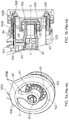
Figure 1 illustrates a staged fuel injector having a prior known configuration. The injector is shown in perspective view from an upstream end (Figure 1 (a) ) and in schematic axial cross section (Figure 1(b) ). The injector comprises a pilotinner air swirler 101 arranged on a centreline C-C. Immediately radially outboard of the pilotinner air swirler 101 is apilot fuel swirler 105. Amain fuel swirler 106 sits radially outboard of thepilot fuel swirler 105. A maininner air swirler 102 sits radially between thepilot fuel swirler 105 and themain fuel swirler 106. In the embodiment shown (though this is not essential to the invention), the main fuel swirler branches to provide a pilotouter air swirler 104 which sits radially between thepilot fuel swirler 105 and a radiallyouter branch 102. Afuel tube 107 extends radially outwardly and is arranged to deliver fuel to themain fuel swirler 106. Aseparate conduit 108 extends from thefuel tube 107 to the maininner air swirler 102 to deliver fuel to thepilot fuel swirler 105. At an upstream end of the injector assembly, a heatprotective casing 103 is arranged to cover upstream ends of thefuel swirlers air swirlers - The
casing 103 has an upstream facing radially extending surface which inclines from an upstream position proximal to thefuel tube 107 to a downstream position distal to thefuel tube 107. It will be appreciated that the walls of the maininner air swirler 102 terminate at different axial positions at the upstream end. This shaping has been developed to allow access behind the fuel injector for assembly, repair and maintenance and also to keep weight down. - The various components of the fuel injector are welded at the weld zones marked W1 (pilot
inner air swirler 101 to casing 103), W2 (maininner air swirler 102 to casing 103) W3 (a radially outer section of thecasing 103a to a radially inner section of thecasing 103b), W4 (walls inner air swirler 102 to walls ofmain fuel swirler 106 and pilot fuel swirler 105). Typically, these welds join very thin (for example about 0.03 inches/ 0.75mm) high strength alloys together or to thicker sections. - Welding processes are inherently difficult to control and so it is difficult to achieve easily repeatable results on similar components. The nature of the thin-thick material and geometry of these joints means that the welding process can add more heat to some components than others. Consequently, welds may pull the components into various distortions and interferences with each other resulting in inconsistent joints and dimensional stack ups from one injector to the next. Additionally, gaps in air swirler ducts can be made inconsistent within a single injector, causing potential unwanted air disturbances and consequent inefficiencies in the fuel burn.
- The back side of the welds also is unpredictable. It can leave inherent sharp valleys that can cause cracks to start sooner than expected due to the nature of the vibrations that may be experienced by the injector when in use in a gas turbine engine. The complicated geometry is not conducive to automated welding methods. Weld beads from part to part or even on the same part can vary in size and shape small differences cumulatively having a significant effect.
- There is a desire to provide a staged fuel injector which can be manufactured by a more repeatable process and hence a more consistent and predictable behaviour in operation.
- The present invention provides a staged fuel injector comprising a pilot inner air swirler arranged along a centre axis of the injector, a pilot fuel swirler arranged radially outboard of the pilot inner air swirler, a main inner air swirler arranged radially outboard of the pilot fuel swirler and a main fuel swirler arranged radially outboard of the pilot fuel swirler; a fuel tube arranged in fluid communication with the pilot fuel swirler and the main fuel swirler for delivering fuel to the pilot fuel swirler and the main fuel swirler and a heat protective casing enclosing the fuel tube, the pilot fuel swirler and the main fuel swirler, wherein walls of the pilot and main inner air swirlers extend axially, together terminating in a common radial plane with the heat protective casing and adjacent axially extending walls of the heat protective casing, the pilot inner air swirler, and the main inner air swirler are joined by a braze.
- Prior known fuel injectors have component designs which are not conducive to brazing. The inventors have redesigned multiple components to provide components which can be conveniently assembled and consistently joined using a braze.
- For an effective braze joint, components require an elongate overlap. A small basin is provided between the surfaces to be brazed, typically in the form of an annularly extending recess in one or both of the walls to be joined.
- The main inner air swirler may be configured to branch at a downstream end to form an intermediate and radially outer air swirler. The intermediate and radially outer air swirler may be integrally formed or may comprise separate components joined together. Where these swirlers comprise separate components, they may be joined by braze. For example, the intermediate air swirler has a radially inner axially extending wall which is brazed to a wall of the pilot fuel swirler.
- Components of the fuel injector are configured to be assembled. The feed arm forms the main structural component and receives other components and/or component sub-assemblies from the downstream or upstream side. Between adjacent components and component sub-assemblies, in the axially extending walls, is provided a basin which is filled with braze material. Once the assembly is complete, the assembly is subjected to heat sufficient to melt the braze material and form the braze joints. The process is well suited to batch processing of multiple injectors. A benefit of the process is that, by careful control of tolerances in the manufacture of the components of the assembly, a consistent and predictable end product can be achieved.
- Parts of the axially extending walls of the main inner air swirler may include a radially extending passage through which the fuel tube extends to an inlet of the pilot fuel swirler. A radially outer axially extending wall of the main inner air swirler may be joined by a braze to an axially extending wall of the main fuel swirler at a location downstream of the casing and a radially inner wall of the main inner air swirler may be joined by a braze to an axially extending wall of the primary fuel swirler at a location downstream of the casing.
- In one option, the assembly process may involve prior thermal resizing of components. This allows a tighter fit to be achieved between components, reducing the impact of vibrations on the assembly. The Assignee's previously published patent
US 7,926,178 describes a thermal resizing brazing method for brazing together components of a fuel swirler. The present invention provides an assembly including novel designs of other components of the fuel injector which collectively permit the entire fuel injector assembly to be brazed together in a single heating step in preference to multiple brazing/welding steps. - In the context of the claim, the terms "upstream" and "downstream" should be understood to refer to the direction of flow of fuel and air through the nozzle, typically this will be the same as the direction of flow of a working fluid passing through a gas turbine engine in which the injector is incorporated.
- In another aspect, the invention comprises a gas turbine engine incorporating a staged fuel injector as referred to above.
- In brazing, two surfaces (often of dissimilar material) are aligned either side of a melting and flowing filler metal, the filler metal having a lower melting point than the adjoining metal. The filler metal spreads across the interface between the two surfaces and commences bonding with each surface. On cooling of the filler material at the interface, the two surfaces become joined together.
US patent publication no. US7926178 (the content of which is incorporated herein by reference) describes a brazing method suitable for use in the manufacture of fuel injectors in accordance with the present invention. In this method, thermal resizing of one or both components is performed to ensure very close contact at the braze interface when the components are returned to equal temperature. An advantage of brazing is the ability to join the same or different metals with considerable strength. - An embodiment of the invention will now be further described with reference to the accompanying Figure in which;
-
Figure 1 (a) shows a perspective view from an upstream end of a staged fuel injector as known from the prior art; -
Figure 1(b) shows a schematic cross sectional view of the staged fuel injector ofFigure 1(a) ; -
Figure 2 shows in cross section, an embodiment of a staged fuel injector in accordance with the present invention; -
Figure 3 shows a sectional side view of a gas turbine engine as is known from the prior art. -
Figures 1 (a) and 1(b) are described in greater detail in the "Background of Invention and Related Art" section above. -
Figure 2 illustrates an embodiment of a staged fuel injector of the invention. The staged fuel injector is configured to be assembled and subsequently brazed in a single heating step. - As can be seen the staged fuel injector of the embodiment comprises a pilot inner air swirler 1 arranged on an axial centreline C-C of the staged fuel injector. At an upstream end, the radially
outer wall 1 a of the pilot inner air swirler 1 is received in a central aperture of an annular heat protective casing 3 which extends in a plane R-R which is substantially orthogonal to the axial centreline C-C. Within the radially outer wall, in an axial position adjacent a facing radial wall of the casing 3 is provided an annularly extending recess into which a braze material is provided prior to insertion of the pilot inner air swirler 1 into the central aperture of the casing 3. Arranged radially adjacent and outboard of the pilot inner air swirler 1 is thepilot fuel swirler 5. Whilst other configurations of fuel swirler could be substituted without departing from the scope of the invention as claimed, thepilot fuel swirler 5 of the shown embodiment comprises a dual walled component, the walls together defining flow passages for fuel delivered to an inlet from a fuelfeed arm feed 7 via aconduit 8. The walls of thepilot fuel swirler 5 may be configured and assembled in accordance with the method described in prior published patentUS7926178 . These walls may be brazed together prior to insertion in the staged fuel injector assembly, or may be brazed as part of a single heating operation used to braze components of the entire assembly together. The radiallyouter wall 5a of thepilot fuel swirler 5 extends radially outwardly at an upstream end and turns back to extend axially and define an annular space. The radially outer wall enclosing the annular space serves as aninner wall 6b of a dual walled main fuel swirler which has a similar construction to thepilot fuel swirler 5. The walls of themain fuel swirler 6 may be configured and assembled in accordance with the method described in prior published patentUS7926178 . These walls may be brazed together prior to insertion in the staged fuel injector assembly, or may be brazed as part of a single heating operation used to braze components of the entire assembly together. In the annular space there is inserted a maininner air swirler 2 which is bounded by radially inner andouter walls radially extending wall 2c. Theaxially extending walls walls main fuel swirlers wall 9 divides a downstream end of the main inner air swirler into two radiallyadjacent swirler passages air swirler walls pilot fuel swirlers outer wall 10a is positioned radially outboard of themain fuel swirler 6 defining a bounding wall of an outer air swirler 10. The outer air swirler 10 is optionally formed integrally with the maininner air swirler 2. A radially inner wall of the outer air swirler 10 may be brazed to a radially adjacent wall which may form part of the heat protective casing and is radially outboard of themain fuel swirler 6. - With reference to
Figure 3 , a gas turbine engine is generally indicated at 310, having a principal androtational axis 311. Theengine 310 comprises, in axial flow series, anair intake 312, apropulsive fan 313, a high-pressure compressor 314,combustion equipment 315, a high-pressure turbine 316, a low-pressure turbine 317 and anexhaust nozzle 318. Anacelle 320 generally surrounds theengine 310 and defines theintake 312. - The
gas turbine engine 310 works in the conventional manner so that air entering theintake 312 is accelerated by thefan 313 to produce two air flows: a first air flow into the high-pressure compressor 314 and a second air flow which passes through abypass duct 321 to provide propulsive thrust. The high-pressure compressor 314 compresses the air flow directed into it before delivering that air to thecombustion equipment 315. - In the
combustion equipment 315 the air flow is mixed with fuel and the mixture combusted. The resultant hot combustion products then expand through, and thereby drive the high and low-pressure turbines nozzle 318 to provide additional propulsive thrust. The high 316 and low 317 pressure turbines drive respectively thehigh pressure compressor 314 and the fan 13, each by suitable interconnecting shaft. - Other gas turbine engines to which the present disclosure may be applied may have alternative configurations. By way of example such engines may have an alternative number of interconnecting shafts (e.g. three) and/or an alternative number of compressors and/or turbines. Further the engine may comprise a gearbox provided in the drive train from a turbine to a compressor and/or fan. The engine may be configured as a turbojet engine. The invention is applicable to any of this variety of engine configurations.
- Within the combustion equipment sits a fuel injector which may, for example, have the configuration of a staged fuel injector in accordance with the invention described herein.
Claims (11)
- A staged fuel injector comprising a pilot inner air swirler (1) arranged along a centre axis C-C of the injector, a pilot fuel swirler (5) arranged radially outboard of the pilot inner air swirler (1), a main inner air swirler (2) arranged radially outboard of the pilot fuel swirler (5) and a main fuel swirler (6) arranged radially outboard of the pilot fuel swirler (5); a fuel tube (7) arranged in fluid communication with the pilot fuel swirler (5) and the main fuel swirler (6) for delivering fuel to the pilot fuel swirler (5) and the main fuel swirler (6) and a heat protective casing (3) enclosing the fuel tube (7), the pilot fuel swirler (5) and the main fuel swirler (6), wherein walls of the pilot and main inner air swirlers (1,2) extend axially, together terminating in a common radial plane with the heat protective casing (3) and adjacent axially extending walls of the heat protective casing (3), the pilot inner air swirler (1), and the main inner air swirler (2) are joined by a braze.
- A staged fuel injector as claimed in claim 1 wherein the main inner air swirler (2) branches at a downstream end to form an intermediate outer air swirler and a radially outer air swirler.
- A staged fuel injector as claimed in claim 1 or claim 2 wherein the intermediate outer air swirler and the radially outer air swirler are integrally formed.
- A staged fuel injector as claimed in claim 2 wherein the intermediate outer air swirler and the radially outer air swirler are formed from separate components which are joined by a braze.
- A staged fuel injector as claimed in any preceding claim wherein component and/or component sub-assemblies of the fuel injector are configured to be assembled, in sequence, in an upstream to downstream direction, the casing forming the most upstream end of the assembly, are assembled with braze between circumferentially facing surfaces of the components and are heated to complete the brazing process after assembly.
- A gas turbine engine having a combustor, the combustor incorporating a staged fuel injector according to any of claims 1 to 5.
- A method for manufacturing a staged fuel injector, the staged fuel injector comprising; a pilot inner air swirler, a pilot fuel swirler, a main inner air swirler and a main fuel swirler; a fuel tube for delivering fuel to the pilot fuel swirler and the main fuel swirler and a heat protective casing enclosing the fuel feed arm, the pilot fuel swirler and the main fuel swirler, wherein axially extending walls of the pilot and main inner air swirlers and the heat protective casing are configured, on assembly, to terminate in a common radial plane and are configured to receive a deposit of braze between adjacent surfaces of the axially extending walls when assembled, the method comprising;
depositing braze on the (to be) adjacent faces of the axially extending walls. inserting the pilot inner air swirler into the heat protective casing with central axes of the pilot inner air swirler and heat protective casing substantially in coaxial alignment and ends of the axially extending walls substantially aligned in a common radial plane,
arranging the pilot fuel swirler and the main fuel swirlers radially outboard of the pilot inner air swirler, with the main fuel swirler radially outboard of the pilot fuel swirler and each in substantially coaxial alignment with the pilot inner air swirler and heat protective casing and ends of the axially extending walls substantially aligned in the common radial plane,
arranging the main inner air swirler between the pilot fuel swirler and the main fuel swirler in substantially coaxial alignment with the pilot inner air swirler and heat protective casing and ends of the axially extending walls substantially aligned in the common radial plane, thereby to provide an assembled staged fuel injector applying heat to the assembled staged fuel injector sufficient to cause the braze to melt,
allowing the assembled staged fuel injector to cool thereby forming brazed joints between the adjacent surfaces of the axially extending walls. - A method as claimed in claim 7 wherein the main inner air swirler has a radially outer axially extending wall which is arranged, on assembly to sit adjacent an axially extending wall of the main fuel swirler at a location downstream of the common radial plane and a radially inner axially extending wall arranged on assembly to sit adjacent an axially extending wall of the primary fuel swirler at a location downstream of the common radial plane, wherein adjacent surfaces of (to be) axially adjacent surfaces of the axially extending walls are configured to receive a deposit of braze therebetween and braze is deposited therebetween prior to arranging the main inner air swirler between the pilot fuel swirler and the main fuel swirler.
- A method as claimed in claim 7 or claim 8 further comprising thermally resizing of one or more of the pilot inner air swirler, pilot fuel swirler, main inner air swirler, main fuel swirler and casing as a preliminary step to assembling the assembled staged fuel injector.
- A method as claimed in any of claims 7 to 9 wherein adjacent surfaces of the axially extending walls include a small basin configured to receive the braze.
- A method as claimed in claim 10 wherein the small basin is in the form of an annularly extending recess in one or both of the walls to be joined.
Applications Claiming Priority (1)
| Application Number | Priority Date | Filing Date | Title |
|---|---|---|---|
| US201662315973P | 2016-03-31 | 2016-03-31 |
Publications (2)
| Publication Number | Publication Date |
|---|---|
| EP3225915A1 true EP3225915A1 (en) | 2017-10-04 |
| EP3225915B1 EP3225915B1 (en) | 2019-02-06 |
Family
ID=58192240
Family Applications (1)
| Application Number | Title | Priority Date | Filing Date |
|---|---|---|---|
| EP17158647.2A Active EP3225915B1 (en) | 2016-03-31 | 2017-03-01 | Fuel injector and method of manufactering the same |
Country Status (2)
| Country | Link |
|---|---|
| US (1) | US10429071B2 (en) |
| EP (1) | EP3225915B1 (en) |
Cited By (2)
| Publication number | Priority date | Publication date | Assignee | Title |
|---|---|---|---|---|
| US11156164B2 (en) | 2019-05-21 | 2021-10-26 | General Electric Company | System and method for high frequency accoustic dampers with caps |
| US11174792B2 (en) | 2019-05-21 | 2021-11-16 | General Electric Company | System and method for high frequency acoustic dampers with baffles |
Families Citing this family (4)
| Publication number | Priority date | Publication date | Assignee | Title |
|---|---|---|---|---|
| US11175045B2 (en) | 2018-01-04 | 2021-11-16 | General Electric Company | Fuel nozzle for gas turbine engine combustor |
| GB202307700D0 (en) * | 2023-05-23 | 2023-07-05 | Rolls Royce Plc | An improved combustor apparatus |
| GB202307701D0 (en) * | 2023-05-23 | 2023-07-05 | Rolls Royce Plc | An improved combustor apparatus |
| US20260063296A1 (en) * | 2024-08-30 | 2026-03-05 | Pratt & Whitney Canada Corp. | Spill return fuel nozzles for usage as start nozzles |
Citations (4)
| Publication number | Priority date | Publication date | Assignee | Title |
|---|---|---|---|---|
| GB1491383A (en) * | 1974-10-07 | 1977-11-09 | Parker Hannifin Corp | Air-atomising fuel nozzle |
| EP1719950A2 (en) * | 2005-05-04 | 2006-11-08 | Delavan Inc | Lean direct injection atomizer for gas turbine engines |
| US20090255120A1 (en) * | 2008-04-11 | 2009-10-15 | General Electric Company | Method of assembling a fuel nozzle |
| US7926178B2 (en) | 2007-11-30 | 2011-04-19 | Delavan Inc | Method of fuel nozzle construction |
Family Cites Families (42)
| Publication number | Priority date | Publication date | Assignee | Title |
|---|---|---|---|---|
| FR2235274B1 (en) * | 1973-06-28 | 1976-09-17 | Snecma | |
| US5505045A (en) * | 1992-11-09 | 1996-04-09 | Fuel Systems Textron, Inc. | Fuel injector assembly with first and second fuel injectors and inner, outer, and intermediate air discharge chambers |
| US5511375A (en) | 1994-09-12 | 1996-04-30 | General Electric Company | Dual fuel mixer for gas turbine combustor |
| US5701732A (en) * | 1995-01-24 | 1997-12-30 | Delavan Inc. | Method and apparatus for purging of gas turbine injectors |
| US5761907A (en) * | 1995-12-11 | 1998-06-09 | Parker-Hannifin Corporation | Thermal gradient dispersing heatshield assembly |
| US5865024A (en) | 1997-01-14 | 1999-02-02 | General Electric Company | Dual fuel mixer for gas turbine combustor |
| US6141967A (en) | 1998-01-09 | 2000-11-07 | General Electric Company | Air fuel mixer for gas turbine combustor |
| US6883332B2 (en) | 1999-05-07 | 2005-04-26 | Parker-Hannifin Corporation | Fuel nozzle for turbine combustion engines having aerodynamic turning vanes |
| US6460344B1 (en) | 1999-05-07 | 2002-10-08 | Parker-Hannifin Corporation | Fuel atomization method for turbine combustion engines having aerodynamic turning vanes |
| US6272840B1 (en) | 2000-01-13 | 2001-08-14 | Cfd Research Corporation | Piloted airblast lean direct fuel injector |
| US6389815B1 (en) * | 2000-09-08 | 2002-05-21 | General Electric Company | Fuel nozzle assembly for reduced exhaust emissions |
| US6363726B1 (en) * | 2000-09-29 | 2002-04-02 | General Electric Company | Mixer having multiple swirlers |
| US6622488B2 (en) * | 2001-03-21 | 2003-09-23 | Parker-Hannifin Corporation | Pure airblast nozzle |
| US6418726B1 (en) * | 2001-05-31 | 2002-07-16 | General Electric Company | Method and apparatus for controlling combustor emissions |
| US6755024B1 (en) | 2001-08-23 | 2004-06-29 | Delavan Inc. | Multiplex injector |
| US6993916B2 (en) | 2004-06-08 | 2006-02-07 | General Electric Company | Burner tube and method for mixing air and gas in a gas turbine engine |
| DE102004059882A1 (en) | 2004-12-10 | 2006-06-22 | Rolls-Royce Deutschland Ltd & Co Kg | Lean pre-mixing burner for combustion chamber, has main air-ring channel with integrated swirl units that are designed as aerodynamic profiled and/or formed air guide vanes that divert air stream into channel in preset angle |
| JP4476176B2 (en) | 2005-06-06 | 2010-06-09 | 三菱重工業株式会社 | Gas turbine premixed combustion burner |
| JP4486549B2 (en) | 2005-06-06 | 2010-06-23 | 三菱重工業株式会社 | Gas turbine combustor |
| GB2439097B (en) | 2006-06-15 | 2008-10-29 | Rolls Royce Plc | Fuel injector |
| US20080078183A1 (en) | 2006-10-03 | 2008-04-03 | General Electric Company | Liquid fuel enhancement for natural gas swirl stabilized nozzle and method |
| US7908864B2 (en) | 2006-10-06 | 2011-03-22 | General Electric Company | Combustor nozzle for a fuel-flexible combustion system |
| US8015815B2 (en) * | 2007-04-18 | 2011-09-13 | Parker-Hannifin Corporation | Fuel injector nozzles, with labyrinth grooves, for gas turbine engines |
| JP4959524B2 (en) | 2007-11-29 | 2012-06-27 | 三菱重工業株式会社 | Burning burner |
| US8806871B2 (en) * | 2008-04-11 | 2014-08-19 | General Electric Company | Fuel nozzle |
| US8061142B2 (en) * | 2008-04-11 | 2011-11-22 | General Electric Company | Mixer for a combustor |
| US8607571B2 (en) * | 2009-09-18 | 2013-12-17 | Delavan Inc | Lean burn injectors having a main fuel circuit and one of multiple pilot fuel circuits with prefiliming air-blast atomizers |
| US9046039B2 (en) * | 2008-05-06 | 2015-06-02 | Rolls-Royce Plc | Staged pilots in pure airblast injectors for gas turbine engines |
| US20100263382A1 (en) * | 2009-04-16 | 2010-10-21 | Alfred Albert Mancini | Dual orifice pilot fuel injector |
| GB2481075B (en) | 2010-06-10 | 2012-10-31 | Delavan Inc | Aerodynamic swept vanes for fuel injectors |
| US9310073B2 (en) * | 2011-03-10 | 2016-04-12 | Rolls-Royce Plc | Liquid swirler flow control |
| US8616471B2 (en) * | 2011-05-18 | 2013-12-31 | Delavan Inc | Multipoint injectors with standard envelope characteristics |
| EP2716976B1 (en) * | 2011-06-02 | 2018-10-31 | Kawasaki Jukogyo Kabushiki Kaisha | Gas turbine combustor |
| US9310081B2 (en) * | 2012-05-14 | 2016-04-12 | Delavan Inc. | Methods of fabricating fuel injectors using laser additive deposition |
| CN104781610B (en) * | 2012-11-15 | 2017-03-08 | 通用电气公司 | fuel nozzle heat shield |
| GB201222304D0 (en) * | 2012-12-12 | 2013-01-23 | Rolls Royce Plc | A fuel injector and a gas turbine engine combustion chamber |
| US10591164B2 (en) * | 2015-03-12 | 2020-03-17 | General Electric Company | Fuel nozzle for a gas turbine engine |
| US10001281B2 (en) * | 2015-04-17 | 2018-06-19 | General Electric Company | Fuel nozzle with dual-staged main circuit |
| US9835334B2 (en) * | 2015-09-18 | 2017-12-05 | Delavan Inc. | Air entrance effect |
| GB201516977D0 (en) * | 2015-09-25 | 2015-11-11 | Rolls Royce Plc | A Fuel Injector For A Gas Turbine Engine Combustion Chamber |
| GB2543803B (en) * | 2015-10-29 | 2019-10-30 | Rolls Royce Plc | A combustion chamber assembly |
| US10077714B2 (en) * | 2015-11-06 | 2018-09-18 | Rolls-Royce Plc | Repairable fuel injector |
-
2017
- 2017-03-01 EP EP17158647.2A patent/EP3225915B1/en active Active
- 2017-03-16 US US15/460,776 patent/US10429071B2/en active Active
Patent Citations (4)
| Publication number | Priority date | Publication date | Assignee | Title |
|---|---|---|---|---|
| GB1491383A (en) * | 1974-10-07 | 1977-11-09 | Parker Hannifin Corp | Air-atomising fuel nozzle |
| EP1719950A2 (en) * | 2005-05-04 | 2006-11-08 | Delavan Inc | Lean direct injection atomizer for gas turbine engines |
| US7926178B2 (en) | 2007-11-30 | 2011-04-19 | Delavan Inc | Method of fuel nozzle construction |
| US20090255120A1 (en) * | 2008-04-11 | 2009-10-15 | General Electric Company | Method of assembling a fuel nozzle |
Cited By (2)
| Publication number | Priority date | Publication date | Assignee | Title |
|---|---|---|---|---|
| US11156164B2 (en) | 2019-05-21 | 2021-10-26 | General Electric Company | System and method for high frequency accoustic dampers with caps |
| US11174792B2 (en) | 2019-05-21 | 2021-11-16 | General Electric Company | System and method for high frequency acoustic dampers with baffles |
Also Published As
| Publication number | Publication date |
|---|---|
| US10429071B2 (en) | 2019-10-01 |
| EP3225915B1 (en) | 2019-02-06 |
| US20170284673A1 (en) | 2017-10-05 |
Similar Documents
| Publication | Publication Date | Title |
|---|---|---|
| EP3225915B1 (en) | Fuel injector and method of manufactering the same | |
| JP5419962B2 (en) | Swirler and method of manufacturing | |
| US10072847B2 (en) | Method for repairing a bundled tube fuel injector | |
| EP3165825B1 (en) | Repairable fuel injector | |
| US10041676B2 (en) | Sealed conical-flat dome for flight engine combustors | |
| EP3055537B1 (en) | Combustor wall with tapered cooling cavity | |
| CN111306576B (en) | Combustion section and fuel injector assembly for a heat engine | |
| JP4553093B2 (en) | Combustor dome assembly and manufacturing method thereof | |
| EP3220047A1 (en) | Gas turbine flow sleeve mounting | |
| US20190024895A1 (en) | Combustor dilution structure for gas turbine engine | |
| US11339968B2 (en) | Dual fuel lance with cooling microchannels | |
| CN115539985B (en) | Burner assembly with movable interface dilution opening | |
| CN113864818A (en) | Combustor air flow path | |
| CN110494693A (en) | Single Chamber Capture Vortex Burner | |
| EP2615374A2 (en) | Combustor and method for reducing thermal stresses in a combustor | |
| EP3176505B1 (en) | Fuel injector and method of manufacturing | |
| JP5389250B2 (en) | Burner assembly | |
| WO2009126403A2 (en) | Swirlers and method of manufacturing | |
| US10450880B2 (en) | Air metering baffle assembly | |
| US11828466B2 (en) | Combustor swirler to CMC dome attachment | |
| US20170350321A1 (en) | Bundled Tube Fuel Nozzle Assembly with Tube Extensions |
Legal Events
| Date | Code | Title | Description |
|---|---|---|---|
| PUAI | Public reference made under article 153(3) epc to a published international application that has entered the european phase |
Free format text: ORIGINAL CODE: 0009012 |
|
| STAA | Information on the status of an ep patent application or granted ep patent |
Free format text: STATUS: THE APPLICATION HAS BEEN PUBLISHED |
|
| AK | Designated contracting states |
Kind code of ref document: A1 Designated state(s): AL AT BE BG CH CY CZ DE DK EE ES FI FR GB GR HR HU IE IS IT LI LT LU LV MC MK MT NL NO PL PT RO RS SE SI SK SM TR |
|
| AX | Request for extension of the european patent |
Extension state: BA ME |
|
| STAA | Information on the status of an ep patent application or granted ep patent |
Free format text: STATUS: REQUEST FOR EXAMINATION WAS MADE |
|
| 17P | Request for examination filed |
Effective date: 20180404 |
|
| RBV | Designated contracting states (corrected) |
Designated state(s): AL AT BE BG CH CY CZ DE DK EE ES FI FR GB GR HR HU IE IS IT LI LT LU LV MC MK MT NL NO PL PT RO RS SE SI SK SM TR |
|
| GRAP | Despatch of communication of intention to grant a patent |
Free format text: ORIGINAL CODE: EPIDOSNIGR1 |
|
| STAA | Information on the status of an ep patent application or granted ep patent |
Free format text: STATUS: GRANT OF PATENT IS INTENDED |
|
| INTG | Intention to grant announced |
Effective date: 20181108 |
|
| GRAS | Grant fee paid |
Free format text: ORIGINAL CODE: EPIDOSNIGR3 |
|
| GRAA | (expected) grant |
Free format text: ORIGINAL CODE: 0009210 |
|
| STAA | Information on the status of an ep patent application or granted ep patent |
Free format text: STATUS: THE PATENT HAS BEEN GRANTED |
|
| AK | Designated contracting states |
Kind code of ref document: B1 Designated state(s): AL AT BE BG CH CY CZ DE DK EE ES FI FR GB GR HR HU IE IS IT LI LT LU LV MC MK MT NL NO PL PT RO RS SE SI SK SM TR |
|
| REG | Reference to a national code |
Ref country code: GB Ref legal event code: FG4D |
|
| REG | Reference to a national code |
Ref country code: CH Ref legal event code: EP Ref country code: AT Ref legal event code: REF Ref document number: 1095146 Country of ref document: AT Kind code of ref document: T Effective date: 20190215 |
|
| REG | Reference to a national code |
Ref country code: DE Ref legal event code: R096 Ref document number: 602017002031 Country of ref document: DE |
|
| REG | Reference to a national code |
Ref country code: IE Ref legal event code: FG4D |
|
| REG | Reference to a national code |
Ref country code: NL Ref legal event code: MP Effective date: 20190206 |
|
| REG | Reference to a national code |
Ref country code: LT Ref legal event code: MG4D |
|
| PG25 | Lapsed in a contracting state [announced via postgrant information from national office to epo] |
Ref country code: SE Free format text: LAPSE BECAUSE OF FAILURE TO SUBMIT A TRANSLATION OF THE DESCRIPTION OR TO PAY THE FEE WITHIN THE PRESCRIBED TIME-LIMIT Effective date: 20190206 Ref country code: LT Free format text: LAPSE BECAUSE OF FAILURE TO SUBMIT A TRANSLATION OF THE DESCRIPTION OR TO PAY THE FEE WITHIN THE PRESCRIBED TIME-LIMIT Effective date: 20190206 Ref country code: ES Free format text: LAPSE BECAUSE OF FAILURE TO SUBMIT A TRANSLATION OF THE DESCRIPTION OR TO PAY THE FEE WITHIN THE PRESCRIBED TIME-LIMIT Effective date: 20190206 Ref country code: NL Free format text: LAPSE BECAUSE OF FAILURE TO SUBMIT A TRANSLATION OF THE DESCRIPTION OR TO PAY THE FEE WITHIN THE PRESCRIBED TIME-LIMIT Effective date: 20190206 Ref country code: NO Free format text: LAPSE BECAUSE OF FAILURE TO SUBMIT A TRANSLATION OF THE DESCRIPTION OR TO PAY THE FEE WITHIN THE PRESCRIBED TIME-LIMIT Effective date: 20190506 Ref country code: FI Free format text: LAPSE BECAUSE OF FAILURE TO SUBMIT A TRANSLATION OF THE DESCRIPTION OR TO PAY THE FEE WITHIN THE PRESCRIBED TIME-LIMIT Effective date: 20190206 Ref country code: PT Free format text: LAPSE BECAUSE OF FAILURE TO SUBMIT A TRANSLATION OF THE DESCRIPTION OR TO PAY THE FEE WITHIN THE PRESCRIBED TIME-LIMIT Effective date: 20190606 |
|
| REG | Reference to a national code |
Ref country code: AT Ref legal event code: MK05 Ref document number: 1095146 Country of ref document: AT Kind code of ref document: T Effective date: 20190206 |
|
| PG25 | Lapsed in a contracting state [announced via postgrant information from national office to epo] |
Ref country code: IS Free format text: LAPSE BECAUSE OF FAILURE TO SUBMIT A TRANSLATION OF THE DESCRIPTION OR TO PAY THE FEE WITHIN THE PRESCRIBED TIME-LIMIT Effective date: 20190606 Ref country code: GR Free format text: LAPSE BECAUSE OF FAILURE TO SUBMIT A TRANSLATION OF THE DESCRIPTION OR TO PAY THE FEE WITHIN THE PRESCRIBED TIME-LIMIT Effective date: 20190507 Ref country code: BG Free format text: LAPSE BECAUSE OF FAILURE TO SUBMIT A TRANSLATION OF THE DESCRIPTION OR TO PAY THE FEE WITHIN THE PRESCRIBED TIME-LIMIT Effective date: 20190506 Ref country code: RS Free format text: LAPSE BECAUSE OF FAILURE TO SUBMIT A TRANSLATION OF THE DESCRIPTION OR TO PAY THE FEE WITHIN THE PRESCRIBED TIME-LIMIT Effective date: 20190206 Ref country code: LV Free format text: LAPSE BECAUSE OF FAILURE TO SUBMIT A TRANSLATION OF THE DESCRIPTION OR TO PAY THE FEE WITHIN THE PRESCRIBED TIME-LIMIT Effective date: 20190206 Ref country code: HR Free format text: LAPSE BECAUSE OF FAILURE TO SUBMIT A TRANSLATION OF THE DESCRIPTION OR TO PAY THE FEE WITHIN THE PRESCRIBED TIME-LIMIT Effective date: 20190206 |
|
| PG25 | Lapsed in a contracting state [announced via postgrant information from national office to epo] |
Ref country code: AL Free format text: LAPSE BECAUSE OF FAILURE TO SUBMIT A TRANSLATION OF THE DESCRIPTION OR TO PAY THE FEE WITHIN THE PRESCRIBED TIME-LIMIT Effective date: 20190206 Ref country code: RO Free format text: LAPSE BECAUSE OF FAILURE TO SUBMIT A TRANSLATION OF THE DESCRIPTION OR TO PAY THE FEE WITHIN THE PRESCRIBED TIME-LIMIT Effective date: 20190206 Ref country code: CZ Free format text: LAPSE BECAUSE OF FAILURE TO SUBMIT A TRANSLATION OF THE DESCRIPTION OR TO PAY THE FEE WITHIN THE PRESCRIBED TIME-LIMIT Effective date: 20190206 Ref country code: SK Free format text: LAPSE BECAUSE OF FAILURE TO SUBMIT A TRANSLATION OF THE DESCRIPTION OR TO PAY THE FEE WITHIN THE PRESCRIBED TIME-LIMIT Effective date: 20190206 Ref country code: DK Free format text: LAPSE BECAUSE OF FAILURE TO SUBMIT A TRANSLATION OF THE DESCRIPTION OR TO PAY THE FEE WITHIN THE PRESCRIBED TIME-LIMIT Effective date: 20190206 Ref country code: IT Free format text: LAPSE BECAUSE OF FAILURE TO SUBMIT A TRANSLATION OF THE DESCRIPTION OR TO PAY THE FEE WITHIN THE PRESCRIBED TIME-LIMIT Effective date: 20190206 Ref country code: EE Free format text: LAPSE BECAUSE OF FAILURE TO SUBMIT A TRANSLATION OF THE DESCRIPTION OR TO PAY THE FEE WITHIN THE PRESCRIBED TIME-LIMIT Effective date: 20190206 |
|
| REG | Reference to a national code |
Ref country code: DE Ref legal event code: R097 Ref document number: 602017002031 Country of ref document: DE |
|
| PG25 | Lapsed in a contracting state [announced via postgrant information from national office to epo] |
Ref country code: LU Free format text: LAPSE BECAUSE OF NON-PAYMENT OF DUE FEES Effective date: 20190301 Ref country code: SM Free format text: LAPSE BECAUSE OF FAILURE TO SUBMIT A TRANSLATION OF THE DESCRIPTION OR TO PAY THE FEE WITHIN THE PRESCRIBED TIME-LIMIT Effective date: 20190206 Ref country code: PL Free format text: LAPSE BECAUSE OF FAILURE TO SUBMIT A TRANSLATION OF THE DESCRIPTION OR TO PAY THE FEE WITHIN THE PRESCRIBED TIME-LIMIT Effective date: 20190206 |
|
| PLBE | No opposition filed within time limit |
Free format text: ORIGINAL CODE: 0009261 |
|
| REG | Reference to a national code |
Ref country code: BE Ref legal event code: MM Effective date: 20190331 |
|
| STAA | Information on the status of an ep patent application or granted ep patent |
Free format text: STATUS: NO OPPOSITION FILED WITHIN TIME LIMIT |
|
| PG25 | Lapsed in a contracting state [announced via postgrant information from national office to epo] |
Ref country code: MC Free format text: LAPSE BECAUSE OF FAILURE TO SUBMIT A TRANSLATION OF THE DESCRIPTION OR TO PAY THE FEE WITHIN THE PRESCRIBED TIME-LIMIT Effective date: 20190206 Ref country code: AT Free format text: LAPSE BECAUSE OF FAILURE TO SUBMIT A TRANSLATION OF THE DESCRIPTION OR TO PAY THE FEE WITHIN THE PRESCRIBED TIME-LIMIT Effective date: 20190206 |
|
| 26N | No opposition filed |
Effective date: 20191107 |
|
| PG25 | Lapsed in a contracting state [announced via postgrant information from national office to epo] |
Ref country code: IE Free format text: LAPSE BECAUSE OF NON-PAYMENT OF DUE FEES Effective date: 20190301 |
|
| PG25 | Lapsed in a contracting state [announced via postgrant information from national office to epo] |
Ref country code: SI Free format text: LAPSE BECAUSE OF FAILURE TO SUBMIT A TRANSLATION OF THE DESCRIPTION OR TO PAY THE FEE WITHIN THE PRESCRIBED TIME-LIMIT Effective date: 20190206 Ref country code: BE Free format text: LAPSE BECAUSE OF NON-PAYMENT OF DUE FEES Effective date: 20190331 |
|
| PG25 | Lapsed in a contracting state [announced via postgrant information from national office to epo] |
Ref country code: TR Free format text: LAPSE BECAUSE OF FAILURE TO SUBMIT A TRANSLATION OF THE DESCRIPTION OR TO PAY THE FEE WITHIN THE PRESCRIBED TIME-LIMIT Effective date: 20190206 |
|
| PG25 | Lapsed in a contracting state [announced via postgrant information from national office to epo] |
Ref country code: MT Free format text: LAPSE BECAUSE OF NON-PAYMENT OF DUE FEES Effective date: 20190301 |
|
| REG | Reference to a national code |
Ref country code: CH Ref legal event code: PL |
|
| PG25 | Lapsed in a contracting state [announced via postgrant information from national office to epo] |
Ref country code: CH Free format text: LAPSE BECAUSE OF NON-PAYMENT OF DUE FEES Effective date: 20200331 Ref country code: LI Free format text: LAPSE BECAUSE OF NON-PAYMENT OF DUE FEES Effective date: 20200331 |
|
| PG25 | Lapsed in a contracting state [announced via postgrant information from national office to epo] |
Ref country code: CY Free format text: LAPSE BECAUSE OF FAILURE TO SUBMIT A TRANSLATION OF THE DESCRIPTION OR TO PAY THE FEE WITHIN THE PRESCRIBED TIME-LIMIT Effective date: 20190206 |
|
| PG25 | Lapsed in a contracting state [announced via postgrant information from national office to epo] |
Ref country code: HU Free format text: LAPSE BECAUSE OF FAILURE TO SUBMIT A TRANSLATION OF THE DESCRIPTION OR TO PAY THE FEE WITHIN THE PRESCRIBED TIME-LIMIT; INVALID AB INITIO Effective date: 20170301 |
|
| PG25 | Lapsed in a contracting state [announced via postgrant information from national office to epo] |
Ref country code: MK Free format text: LAPSE BECAUSE OF FAILURE TO SUBMIT A TRANSLATION OF THE DESCRIPTION OR TO PAY THE FEE WITHIN THE PRESCRIBED TIME-LIMIT Effective date: 20190206 |
|
| P01 | Opt-out of the competence of the unified patent court (upc) registered |
Effective date: 20230528 |
|
| PGFP | Annual fee paid to national office [announced via postgrant information from national office to epo] |
Ref country code: GB Payment date: 20260323 Year of fee payment: 10 |
|
| PGFP | Annual fee paid to national office [announced via postgrant information from national office to epo] |
Ref country code: DE Payment date: 20260320 Year of fee payment: 10 |
|
| PGFP | Annual fee paid to national office [announced via postgrant information from national office to epo] |
Ref country code: FR Payment date: 20260323 Year of fee payment: 10 |