EP3225902A1 - Ensemble de distribution de gaz comprenant un récipient de gaz équipé d'un bloc robinet et d'une bague support d'informations - Google Patents
Ensemble de distribution de gaz comprenant un récipient de gaz équipé d'un bloc robinet et d'une bague support d'informations Download PDFInfo
- Publication number
- EP3225902A1 EP3225902A1 EP17157105.2A EP17157105A EP3225902A1 EP 3225902 A1 EP3225902 A1 EP 3225902A1 EP 17157105 A EP17157105 A EP 17157105A EP 3225902 A1 EP3225902 A1 EP 3225902A1
- Authority
- EP
- European Patent Office
- Prior art keywords
- ring
- main body
- information carrier
- valve block
- gas
- Prior art date
- Legal status (The legal status is an assumption and is not a legal conclusion. Google has not performed a legal analysis and makes no representation as to the accuracy of the status listed.)
- Withdrawn
Links
- 230000001681 protective effect Effects 0.000 claims abstract description 15
- 239000004033 plastic Substances 0.000 claims abstract description 9
- 239000002184 metal Substances 0.000 claims description 4
- 239000007789 gas Substances 0.000 description 60
- 208000031968 Cadaver Diseases 0.000 description 14
- 239000000203 mixture Substances 0.000 description 6
- 238000012550 audit Methods 0.000 description 3
- 230000001105 regulatory effect Effects 0.000 description 3
- 238000004891 communication Methods 0.000 description 2
- 239000002131 composite material Substances 0.000 description 2
- 239000000463 material Substances 0.000 description 2
- 238000000465 moulding Methods 0.000 description 2
- 230000008520 organization Effects 0.000 description 2
- 230000002093 peripheral effect Effects 0.000 description 2
- 238000013102 re-test Methods 0.000 description 2
- 241000219504 Caryophyllales Species 0.000 description 1
- QVGXLLKOCUKJST-UHFFFAOYSA-N atomic oxygen Chemical compound [O] QVGXLLKOCUKJST-UHFFFAOYSA-N 0.000 description 1
- 230000001276 controlling effect Effects 0.000 description 1
- 230000008878 coupling Effects 0.000 description 1
- 238000010168 coupling process Methods 0.000 description 1
- 238000005859 coupling reaction Methods 0.000 description 1
- 239000000945 filler Substances 0.000 description 1
- 239000012530 fluid Substances 0.000 description 1
- 239000000446 fuel Substances 0.000 description 1
- 238000003780 insertion Methods 0.000 description 1
- 230000037431 insertion Effects 0.000 description 1
- JEIPFZHSYJVQDO-UHFFFAOYSA-N iron(III) oxide Inorganic materials O=[Fe]O[Fe]=O JEIPFZHSYJVQDO-UHFFFAOYSA-N 0.000 description 1
- 238000004519 manufacturing process Methods 0.000 description 1
- 239000001301 oxygen Substances 0.000 description 1
- 229910052760 oxygen Inorganic materials 0.000 description 1
- 239000002985 plastic film Substances 0.000 description 1
- 229920000642 polymer Polymers 0.000 description 1
- 230000000717 retained effect Effects 0.000 description 1
Images


Classifications
-
- F—MECHANICAL ENGINEERING; LIGHTING; HEATING; WEAPONS; BLASTING
- F17—STORING OR DISTRIBUTING GASES OR LIQUIDS
- F17C—VESSELS FOR CONTAINING OR STORING COMPRESSED, LIQUEFIED OR SOLIDIFIED GASES; FIXED-CAPACITY GAS-HOLDERS; FILLING VESSELS WITH, OR DISCHARGING FROM VESSELS, COMPRESSED, LIQUEFIED, OR SOLIDIFIED GASES
- F17C13/00—Details of vessels or of the filling or discharging of vessels
-
- F—MECHANICAL ENGINEERING; LIGHTING; HEATING; WEAPONS; BLASTING
- F17—STORING OR DISTRIBUTING GASES OR LIQUIDS
- F17C—VESSELS FOR CONTAINING OR STORING COMPRESSED, LIQUEFIED OR SOLIDIFIED GASES; FIXED-CAPACITY GAS-HOLDERS; FILLING VESSELS WITH, OR DISCHARGING FROM VESSELS, COMPRESSED, LIQUEFIED, OR SOLIDIFIED GASES
- F17C2201/00—Vessel construction, in particular geometry, arrangement or size
- F17C2201/01—Shape
- F17C2201/0104—Shape cylindrical
-
- F—MECHANICAL ENGINEERING; LIGHTING; HEATING; WEAPONS; BLASTING
- F17—STORING OR DISTRIBUTING GASES OR LIQUIDS
- F17C—VESSELS FOR CONTAINING OR STORING COMPRESSED, LIQUEFIED OR SOLIDIFIED GASES; FIXED-CAPACITY GAS-HOLDERS; FILLING VESSELS WITH, OR DISCHARGING FROM VESSELS, COMPRESSED, LIQUEFIED, OR SOLIDIFIED GASES
- F17C2201/00—Vessel construction, in particular geometry, arrangement or size
- F17C2201/05—Size
- F17C2201/056—Small (<1 m3)
-
- F—MECHANICAL ENGINEERING; LIGHTING; HEATING; WEAPONS; BLASTING
- F17—STORING OR DISTRIBUTING GASES OR LIQUIDS
- F17C—VESSELS FOR CONTAINING OR STORING COMPRESSED, LIQUEFIED OR SOLIDIFIED GASES; FIXED-CAPACITY GAS-HOLDERS; FILLING VESSELS WITH, OR DISCHARGING FROM VESSELS, COMPRESSED, LIQUEFIED, OR SOLIDIFIED GASES
- F17C2201/00—Vessel construction, in particular geometry, arrangement or size
- F17C2201/05—Size
- F17C2201/058—Size portable (<30 l)
-
- F—MECHANICAL ENGINEERING; LIGHTING; HEATING; WEAPONS; BLASTING
- F17—STORING OR DISTRIBUTING GASES OR LIQUIDS
- F17C—VESSELS FOR CONTAINING OR STORING COMPRESSED, LIQUEFIED OR SOLIDIFIED GASES; FIXED-CAPACITY GAS-HOLDERS; FILLING VESSELS WITH, OR DISCHARGING FROM VESSELS, COMPRESSED, LIQUEFIED, OR SOLIDIFIED GASES
- F17C2203/00—Vessel construction, in particular walls or details thereof
- F17C2203/06—Materials for walls or layers thereof; Properties or structures of walls or their materials
- F17C2203/0634—Materials for walls or layers thereof
- F17C2203/0636—Metals
-
- F—MECHANICAL ENGINEERING; LIGHTING; HEATING; WEAPONS; BLASTING
- F17—STORING OR DISTRIBUTING GASES OR LIQUIDS
- F17C—VESSELS FOR CONTAINING OR STORING COMPRESSED, LIQUEFIED OR SOLIDIFIED GASES; FIXED-CAPACITY GAS-HOLDERS; FILLING VESSELS WITH, OR DISCHARGING FROM VESSELS, COMPRESSED, LIQUEFIED, OR SOLIDIFIED GASES
- F17C2203/00—Vessel construction, in particular walls or details thereof
- F17C2203/06—Materials for walls or layers thereof; Properties or structures of walls or their materials
- F17C2203/0634—Materials for walls or layers thereof
- F17C2203/0658—Synthetics
- F17C2203/0663—Synthetics in form of fibers or filaments
-
- F—MECHANICAL ENGINEERING; LIGHTING; HEATING; WEAPONS; BLASTING
- F17—STORING OR DISTRIBUTING GASES OR LIQUIDS
- F17C—VESSELS FOR CONTAINING OR STORING COMPRESSED, LIQUEFIED OR SOLIDIFIED GASES; FIXED-CAPACITY GAS-HOLDERS; FILLING VESSELS WITH, OR DISCHARGING FROM VESSELS, COMPRESSED, LIQUEFIED, OR SOLIDIFIED GASES
- F17C2205/00—Vessel construction, in particular mounting arrangements, attachments or identifications means
- F17C2205/03—Fluid connections, filters, valves, closure means or other attachments
- F17C2205/0302—Fittings, valves, filters, or components in connection with the gas storage device
- F17C2205/0308—Protective caps
-
- F—MECHANICAL ENGINEERING; LIGHTING; HEATING; WEAPONS; BLASTING
- F17—STORING OR DISTRIBUTING GASES OR LIQUIDS
- F17C—VESSELS FOR CONTAINING OR STORING COMPRESSED, LIQUEFIED OR SOLIDIFIED GASES; FIXED-CAPACITY GAS-HOLDERS; FILLING VESSELS WITH, OR DISCHARGING FROM VESSELS, COMPRESSED, LIQUEFIED, OR SOLIDIFIED GASES
- F17C2205/00—Vessel construction, in particular mounting arrangements, attachments or identifications means
- F17C2205/03—Fluid connections, filters, valves, closure means or other attachments
- F17C2205/0302—Fittings, valves, filters, or components in connection with the gas storage device
- F17C2205/0338—Pressure regulators
-
- F—MECHANICAL ENGINEERING; LIGHTING; HEATING; WEAPONS; BLASTING
- F17—STORING OR DISTRIBUTING GASES OR LIQUIDS
- F17C—VESSELS FOR CONTAINING OR STORING COMPRESSED, LIQUEFIED OR SOLIDIFIED GASES; FIXED-CAPACITY GAS-HOLDERS; FILLING VESSELS WITH, OR DISCHARGING FROM VESSELS, COMPRESSED, LIQUEFIED, OR SOLIDIFIED GASES
- F17C2205/00—Vessel construction, in particular mounting arrangements, attachments or identifications means
- F17C2205/03—Fluid connections, filters, valves, closure means or other attachments
- F17C2205/0302—Fittings, valves, filters, or components in connection with the gas storage device
- F17C2205/0382—Constructional details of valves, regulators
-
- F—MECHANICAL ENGINEERING; LIGHTING; HEATING; WEAPONS; BLASTING
- F17—STORING OR DISTRIBUTING GASES OR LIQUIDS
- F17C—VESSELS FOR CONTAINING OR STORING COMPRESSED, LIQUEFIED OR SOLIDIFIED GASES; FIXED-CAPACITY GAS-HOLDERS; FILLING VESSELS WITH, OR DISCHARGING FROM VESSELS, COMPRESSED, LIQUEFIED, OR SOLIDIFIED GASES
- F17C2205/00—Vessel construction, in particular mounting arrangements, attachments or identifications means
- F17C2205/03—Fluid connections, filters, valves, closure means or other attachments
- F17C2205/0388—Arrangement of valves, regulators, filters
- F17C2205/0394—Arrangement of valves, regulators, filters in direct contact with the pressure vessel
-
- F—MECHANICAL ENGINEERING; LIGHTING; HEATING; WEAPONS; BLASTING
- F17—STORING OR DISTRIBUTING GASES OR LIQUIDS
- F17C—VESSELS FOR CONTAINING OR STORING COMPRESSED, LIQUEFIED OR SOLIDIFIED GASES; FIXED-CAPACITY GAS-HOLDERS; FILLING VESSELS WITH, OR DISCHARGING FROM VESSELS, COMPRESSED, LIQUEFIED, OR SOLIDIFIED GASES
- F17C2205/00—Vessel construction, in particular mounting arrangements, attachments or identifications means
- F17C2205/05—Vessel or content identifications, e.g. labels
-
- F—MECHANICAL ENGINEERING; LIGHTING; HEATING; WEAPONS; BLASTING
- F17—STORING OR DISTRIBUTING GASES OR LIQUIDS
- F17C—VESSELS FOR CONTAINING OR STORING COMPRESSED, LIQUEFIED OR SOLIDIFIED GASES; FIXED-CAPACITY GAS-HOLDERS; FILLING VESSELS WITH, OR DISCHARGING FROM VESSELS, COMPRESSED, LIQUEFIED, OR SOLIDIFIED GASES
- F17C2221/00—Handled fluid, in particular type of fluid
- F17C2221/01—Pure fluids
-
- F—MECHANICAL ENGINEERING; LIGHTING; HEATING; WEAPONS; BLASTING
- F17—STORING OR DISTRIBUTING GASES OR LIQUIDS
- F17C—VESSELS FOR CONTAINING OR STORING COMPRESSED, LIQUEFIED OR SOLIDIFIED GASES; FIXED-CAPACITY GAS-HOLDERS; FILLING VESSELS WITH, OR DISCHARGING FROM VESSELS, COMPRESSED, LIQUEFIED, OR SOLIDIFIED GASES
- F17C2221/00—Handled fluid, in particular type of fluid
- F17C2221/03—Mixtures
-
- F—MECHANICAL ENGINEERING; LIGHTING; HEATING; WEAPONS; BLASTING
- F17—STORING OR DISTRIBUTING GASES OR LIQUIDS
- F17C—VESSELS FOR CONTAINING OR STORING COMPRESSED, LIQUEFIED OR SOLIDIFIED GASES; FIXED-CAPACITY GAS-HOLDERS; FILLING VESSELS WITH, OR DISCHARGING FROM VESSELS, COMPRESSED, LIQUEFIED, OR SOLIDIFIED GASES
- F17C2223/00—Handled fluid before transfer, i.e. state of fluid when stored in the vessel or before transfer from the vessel
- F17C2223/01—Handled fluid before transfer, i.e. state of fluid when stored in the vessel or before transfer from the vessel characterised by the phase
- F17C2223/0107—Single phase
- F17C2223/0123—Single phase gaseous, e.g. CNG, GNC
-
- F—MECHANICAL ENGINEERING; LIGHTING; HEATING; WEAPONS; BLASTING
- F17—STORING OR DISTRIBUTING GASES OR LIQUIDS
- F17C—VESSELS FOR CONTAINING OR STORING COMPRESSED, LIQUEFIED OR SOLIDIFIED GASES; FIXED-CAPACITY GAS-HOLDERS; FILLING VESSELS WITH, OR DISCHARGING FROM VESSELS, COMPRESSED, LIQUEFIED, OR SOLIDIFIED GASES
- F17C2223/00—Handled fluid before transfer, i.e. state of fluid when stored in the vessel or before transfer from the vessel
- F17C2223/03—Handled fluid before transfer, i.e. state of fluid when stored in the vessel or before transfer from the vessel characterised by the pressure level
- F17C2223/036—Very high pressure (>80 bar)
-
- F—MECHANICAL ENGINEERING; LIGHTING; HEATING; WEAPONS; BLASTING
- F17—STORING OR DISTRIBUTING GASES OR LIQUIDS
- F17C—VESSELS FOR CONTAINING OR STORING COMPRESSED, LIQUEFIED OR SOLIDIFIED GASES; FIXED-CAPACITY GAS-HOLDERS; FILLING VESSELS WITH, OR DISCHARGING FROM VESSELS, COMPRESSED, LIQUEFIED, OR SOLIDIFIED GASES
- F17C2270/00—Applications
- F17C2270/02—Applications for medical applications
Definitions
- the present invention relates to a gas distribution assembly comprising a gas container equipped with a valve block and a ring-type information carrier ring, in particular an industrial or medical gas cylinder.
- an industrial or medical gas receptacle in particular gas cylinders, must be equipped with an information carrier ring comprising compulsory and / or legal indications and markings relating to the receptacle considered, for example a date and body reference of the assembler.
- valve block equipping the gas container, one (or more) ring support information type vintage ring and / or re-test.
- the information support ring must be easily mounted on the tap, the markings it bears must be easily accessible reading, including when the tap of the container is protected by a protective cover to cover it. The same goes for the vintage ring (expiry year, color, shape) and / or the re-proof ring (assembler's body number, and the date of rise).
- US Patent 5249380 discloses a support with identification markings for a gas bottle, formed of a plastic sheet comprising a plurality of cuts which are positioned facing each other, after folding of the sheet, so as to allow the insertion of said support with markings of identification around the neck of the bottle.
- This solution is however not ideal, especially since it offers only a small marking surface.
- a gas distribution assembly comprising a gas container, such as a gas cylinder, equipped with a valve block, and a support ring information simple to mount on the block valve of the gas container, which ring is easy to manufacture and low cost, can bear the various mandatory or legal markings, and acts as both vintage ring (ie, year of expiry, color, shape) and ring of re-test (ie, assembly organization number and date of assembly).
- the invention proposes a gas distribution assembly comprising a gas container equipped with a valve block on which is mounted a ring, preferably made of plastic, containing all the necessary information, in particular those appearing on a vintage ring (year of expiry, color, shape) and on a re-proof ring (assembly organization number and date of rise).
- This ring is arranged on the faucet of the gas container, such as a gas cylinder, so as to be legible even when the valve is faired a cap / cowl or a protective shell, and is shaped to remain attached to the faucet / bottle assembly.
- the invention also relates to a use of a gas distribution assembly according to the invention comprising a gas container, equipped with a valve block and an information support ring arranged around the valve block, for contain, store and / or supply a gas, in particular a medical or industrial gas.
- the Figure 1 represents a first embodiment of an information carrier ring 1 for a gas container valve 40 according to the present invention, that is to say for an assembly comprising a valve and a gas container according to the present invention .
- This information carrier ring 1 comprises a main body 2 of a ring traversed by a first opening 3, and a hoop 4 secured integrally and pivotally articulated with respect to said main body 2.
- the hoop 4 defines a second opening 5.
- the main body 2 has a ring shape, that is to say a ring or ring, flattened so as to have a front face 2a and a rear face 2b, said front and rear faces 2a, 2b being opposed to each other with respect to the main body 2.
- the hoop 4 fixed is articulated pivotally along a hinge 6 at which the hoop 4 is secured to said main body 2.
- the hinge 6 preferably comprises a fold zone with preformed fold to facilitate folding by pivoting of the arch 4 with respect to the main body 2 of the ring.
- the hoop 4 has an elongated shape, that is to say wired.
- the arch 4 has a general "U" shape or the like, which delimits the second opening 5.
- the main body 2 here a general shape of hollow disc at its center so as to constitute the first opening 3, preferably said first opening 3 is circular or quasi-circular. In general, it is adapted to the geometry of the valve on which the ring must be mounted.
- the assembly of the information carrier ring 1 is preferably made of plastic material, for example of the V2, PC, PP, PA, PE type.
- the plastic material can be colored, for example red, yellow, blue ...
- the assembly of the information carrier ring 1 is made in one piece by molding.
- a reading window 8 is arranged between the first opening 3 and the hinge 6.
- This reading window 8 allows the user to read any information located under said window, that is to say on the valve 20 carrying the information carrier ring 1, for example the serial number of the valve 20.
- the reading window 8 is here of rectangular shape but it can take any other form.
- the main body 2 of the information carrier ring 1 also comprises two walls 7 projecting facing each other and projecting away from the main body 2, that is to say with respect to the outer surface of the main body 2, preferably with respect to its rear face 2b.
- These protruding walls 7 make it possible to position and / or secure the information support ring 1 on a valve 20 of the gas container 40 by taking the body of said valve 20 sandwiched between them.
- the two projecting walls 7 have a general shape in triangle or quasi-triangle.
- the main body 2 is further shaped to have marking areas 9, 10, preferably on its front face 2a.
- the marking areas 9, 10 may include numbers, letters, symbols, drawings or any type of indications or markings useful, including assembly body number, and the date of rise.
- the markings or the like may be made directly in the surface of the main body 2, for example by engraving or molding, or may be carried by labels, plates or the like affixed to said surface of the main body 2.
- the arch 4 is shown in a position rotated relative to the main body 2 of the ring 1, whereas on the Figure 1 it is in the rest position, that is to say not rotated.
- the Figure 3 schematizes the information carrier ring 1 of the Figure 1 arranged on a valve block 20, more simply called valve, which is fixed by screwing, via its threaded base 21, at the neck 41 of a gas container 40, namely a gas cylinder, that is to say in the threaded outlet orifice of said container 40.
- the valve 20 may be of the type with or without integrated expansion valve and comprises the various conventional members and elements of such a valve 40, in particular a filling connector 22, a gas outlet fitting 23, a steering wheel or operating lever controlling the gas outlet, a manometer ....
- the information carrier ring 1 is retained on the valve 40 by means of the first and second openings 3, 5 of the main body 2 of the ring and the hoop 4, respectively, and is held in position by the two protruding walls 7 and arms 11.
- the base 21 of the valve 20 passes through the second opening 5 defined by the arch 4, that is to say that the arch 4 surrounds the base 21 of the valve which typically has a threaded cone shape, then that the filling connector 22 passes through the first opening 3 located in the center of the main body 2 of the ring, that is to say that the main body 2 ring surrounds the filling connector 22 of the valve 20.
- the two walls 7 protruding come to take the filling connector 22 sandwiched by coming laterally on either side of said filling connector 22.
- the Figure 4 is analogous to the Figure 3 but also shows a protective cover 30 formed of two half-shells enclosing all the valve 20 and the neck 41 of the bottle 40 so as to protect these elements.
- the protective cowl 30 may be of polymer or metal.
- FIGS 5A to 5D illustrate the mounting sequence of the information carrier ring 1 of the Figure 1 on the tap 20 of Figures 3 or 4 before mounting the latter on a gas container 40, namely a gas cylinder.
- the hoop 4 is pivoted relative to the main body 2 of the ring of the information carrier ring 1 according to the present invention, which hoop 4 then bends along the hinge 6 with preformed fold zone. encircling the conical base 21 of the valve 20 since the base 21 of the valve 20 then passes through the second opening 5 delimited by the arch 4 ( Fig. 5C ).
- the hinge 6 and the hoop 4 thus constitute a strapping around the base 21 in the form of a threaded cone of the valve 20.
- valve 20 equipped with the information carrier ring 1 according to the present invention is attached to the neck 41 of the container by screwing the threaded base 21 of the valve 20 into the threaded through orifice. said neck 41 and fluidly communicating with the internal volume of the container 40.
- a protective cover 30 can then be fixed around the valve 20 (cf. Fig. 4 ).
- the Figure 6 illustrates three embodiments of an information carrier ring 1 for a valve block / gas container assembly according to the present invention differentiating from each other by the general shape of the main body 2 of the ring, namely a substantially hexagonal disc (left), square (right) or quasi-circular with notches / notches on its outer periphery (center).
- a substantially hexagonal disc left
- square right
- quasi-circular with notches / notches on its outer periphery center
- other forms including a circular disk.
- the Figure 7 shows a gas container 40 equipped with a valve block protected by a protective cowling 30 comprising a cutout 31 formed in its peripheral wall 32 revealing an information carrier 1 according to the present invention arranged around the filler 22 of the block tap.
- the front cutout 31 enables the user (that is to say operators and authorized persons) to have easy access to the information located in the marking areas 9, 10 carried by the information carrier 1 according to the present invention, as well as those in / under the reading window 8, despite the presence of the cowling 30. In other words, there is no need to disassemble the entire cowling 30 to have access the legal and / or regulatory information provided by the ring 1 of the invention.
- the information carrier 1 thus comes to be imprisoned between the protective cowling 30 and the cock 20.
- valve assembly / gas container / information carrier can contain, store and / or supply a gas or gas mixture, in particular a gas or gas mixture medical or industrial.
Landscapes
- Engineering & Computer Science (AREA)
- Mechanical Engineering (AREA)
- General Engineering & Computer Science (AREA)
- Filling Or Discharging Of Gas Storage Vessels (AREA)
Abstract
Description
- La présente invention concerne un ensemble de distribution de gaz comprenant un récipient de gaz équipé d'un bloc robinet et d'une bague support d'informations de type bague millésime, en particulier une bouteille de gaz industriel ou médical.
- Pour des raisons réglementaires, un récipient de gaz industriel ou médical, en particulier les bouteilles de gaz, doit être équipé d'une bague support d'informations comportant des indications et des marquages obligatoires et/ou légaux relatifs au récipient considéré, par exemple une date et la référence organisme de l'assembleur.
- Pour ce faire, on agence usuellement sur le bloc robinet équipant le récipient de gaz, une (ou plusieurs) bague support d'informations de type bague millésime et/ou de ré-épreuve.
- La bague support d'informations doit pouvoir être montée facilement sur le robinet, les marquages qu'elle porte doivent pouvoir être facilement accessibles en lecture, y compris lorsque le robinet du récipient est protégé par un capotage de protection venant le recouvrir. Il en va de même de la bague millésime (année de péremption, couleur, forme) et/ou de la bague de ré-épreuve (numéro organisme de l'assembleur, et la date de monte).
- A l'inverse, la (ou les) bague ne doivent pas pouvoir se détacher intempestivement du bloc robinet équipant le récipient de gaz.
- Le document
US-A-5249380 décrit un support avec marquages d'identification pour bouteille de gaz, formé d'une feuille plastique comprenant plusieurs découpes venant se positionner les unes en face des autres, après pliage de la feuille, de manière à permettre l'insertion dudit support avec marquages d'identification autour du col de la bouteille. Cette solution n'est toutefois pas idéale, notamment car elle n'offre qu'une faible surface de marquage. - Au vu de cela, le problème qui se pose est de proposer ensemble de distribution de gaz comprenant un récipient de gaz, telle une bouteille de gaz, équipé d'un bloc robinet, et une bague support d'informations simple à monter sur le bloc robinet du récipient de gaz, laquelle bague soit aisée à fabriquer et à coût bas, puisse porter les différents marquages obligatoires ou légaux, et fasse office à la fois de bague millésime (i.e., année de péremption, couleur, forme) et de bague de ré-épreuve (i.e., numéro organisme de l'assembleur et date de monte).
- La solution de l'invention repose sur un ensemble de distribution de gaz comprenant :
- un récipient de gaz, en particulier pour bouteille de gaz, équipé d'un bloc robinet comprenant une base filetée et au moins un raccord, et
- une bague support d'informations agencée autour du bloc robinet, ladite bague support d'informations comprenant un corps principal de bague traversé par une première ouverture, et un arceau fixé solidairement et articulé en pivotement par rapport audit corps principal, ledit arceau définissant une seconde ouverture,
- la base filetée du bloc robinet traverse la seconde ouverture de l'arceau de la bague support d'informations, et
- la première ouverture du corps principal de la bague support d'informations est traversée par le raccord du bloc robinet.
- En d'autres termes, l'invention propose un ensemble de distribution de gaz comprenant un récipient de gaz équipé d'un bloc robinet sur lequel est montée une bague, de préférence en plastique, regroupant l'ensemble des informations nécessaires, en particulier celles figurant sur une bague millésime (année de péremption, couleur, forme) et sur une bague de ré-épreuve (numéro organisme de l'assembleur et date de monte). Cette bague est agencée sur le robinet du récipient de gaz, telle une bouteille de gaz, de façon à être lisible même lorsque le robinet est caréné d'un chapeau/capotage ou d'une coque de protection, et est conformée pour rester solidaire de l'assemblage robinet/bouteille.
- Selon le cas, l'ensemble selon l'invention peut comprendre l'une ou plusieurs des caractéristiques techniques suivantes :
- le corps principal de bague de la bague support d'informations comprend un profil adapté à sa fixation sur un bloc robinet.
- l'arceau définissant la seconde ouverture de la bague support d'informations permet l'attache entre robinet et récipient de gaz.
- le corps principal de la bague support d'informations a une forme de bague aplatie présentant une face avant et une face arrière, de préférence il a une forme et/ou une couleur correspondant aux recommandations d'organismes du type AFGC.
- le corps principal de la bague support d'informations a une forme globalement circulaire, ovale, polygonale, notamment carrée, rectangulaire, hexagonale, pentagonale, ou autre.
- l'arceau de la bague support d'informations est articulé en pivotement le long d'au moins une charnière au niveau de laquelle l'arceau vient se solidariser audit corps principal, de préférence autour de la base filetée du bloc robinet.
- le corps principal de la bague support d'informations comprend deux parois en saillie se faisant face et se projetant en éloignement par rapport audit corps principal, de préférence par rapport à la face arrière.
- le corps principal de la bague support d'informations comprend une fenêtre de lecture située entre la première ouverture et ladite au moins une charnière.
- le corps principal de la bague support d'informations est conformé pour présenter au moins une zone de marquage, c'est-à-dire une ou plusieurs zones de marquage. Elles servent à l'apposition des indications, marquages, informations... légales et/ou réglementaires ou autres, notamment numéro organisme de l'assembleur, et la date de monte.
- la ou les zones de marquage sont portées par la face avant du corps principal de la bague support d'informations.
- la bague support d'informations est formée de plastique. Par exemple, un plastique de type V2 pour combustible et oxygène. Tout autre plastique peut néanmoins convenir, tel que PC, PP, PA, PE....
- de manière alternative, la bague support d'informations est formée de métal, par exemple une tôle fine, notamment une tôle peinte.
- de la bague support d'information est formée de plastique coloré, par exemple de couleur rouge.
- il comprend un capotage de protection agencé autour du bloc robinet et de la bague support d'informations.
- le capotage de protection comprend une découpe, de préférence pratiquée dans sa paroi périphérique, laissant apparaître le support d'informations.
- le récipient de gaz comporte un volume interne conçu pour recevoir et conserver un gaz ou mélange gazeux, notamment un gaz industriel ou médical.
- le récipient de gaz comporte un col au niveau duquel débouche un orifice taraudé en communication fluidique avec le volume interne du récipient.
- le récipient de gaz est une bouteille de gaz de forme cylindrique.
- le bloc robinet comprend plusieurs raccords, la première ouverture du corps principal de la bague support d'informations étant traversée par l'un desdits raccords du bloc robinet.
- le raccord est un raccord de remplissage. Cette bague peut cependant être positionnée sur tout autre raccord du robinet.
- le bloc robinet comprend une base filetée en forme de cône, c'est-à-dire conique, ou un filetage droit.
- la base filetée du bloc robinet est fixée par vissage dans l'orifice taraudé porté par le col du récipient de gaz.
- le récipient de gaz est en métal ou en composite.
- le récipient de gaz contient un gaz ou un mélange gazeux, notamment un gaz industriel ou médical.
- Par ailleurs, l'invention concerne aussi une utilisation d'un ensemble de distribution de gaz selon l'invention comprenant un récipient de gaz, équipé d'un bloc robinet et d'une bague support d'informations agencée autour du bloc robinet, pour contenir, stocker et/ou fournir un gaz, en particulier un gaz médical ou industriel.
- L'invention va maintenant être mieux comprise grâce à la description détaillée suivante, faite à titre illustratif mais non limitatif, en référence aux figures annexées parmi lesquelles :
- la
Figure 1 représente un premier mode de réalisation d'une bague support d'informations pour un ensemble comprenant un robinet et un récipient de gaz selon la présente invention, - la
Figure 2 représente un second mode de réalisation d'une bague support d'informations pour un ensemble comprenant un robinet et un récipient de gaz selon la présente invention, - les
Figures 3 et4 schématisent la bague de laFigure 1 agencée sur un robinet équipant un récipient de gaz d'un ensemble comprenant un robinet et un récipient de gaz selon la présente invention, - les
Figures 5A à 5D illustrent la séquence de montage de la bague support d'informations de laFigure 1 sur le robinet desFigures 3 ou4 , - la
Figure 6 illustre trois modes de réalisation d'une bague support d'informations 1 pour un ensemble comprenant un robinet et un récipient de gaz selon la présente invention, et - la
Figure 7 montre un récipient de gaz équipé d'un capotage de protection avec découpe laissant apparaître un support d'informations 1 selon la présente invention. - La
Figure 1 représente un premier mode de réalisation d'une bague support d'informations 1 pour robinet 20 de récipient de gaz 40 selon la présente invention, c'est-à-dire pour un ensemble comprenant un robinet et un récipient de gaz selon la présente invention. - Cette bague support d'informations 1 comprend un corps principal 2 de bague traversé par une première ouverture 3, et un arceau 4 fixé solidairement et articulé en pivotement par rapport audit corps principal 2. L'arceau 4 définit une seconde ouverture 5.
- Dans ce mode de réalisation, le corps principal 2 a une forme de bague, c'est-à-dire de couronne ou d'anneau, aplatie de manière à présenter une face avant 2a et une face arrière 2b, lesdites faces avant et arrières 2a, 2b étant opposées l'une à l'autre par rapport au corps principal 2.
- L'arceau 4 fixé est articulé en pivotement le long d'une charnière 6 au niveau de laquelle l'arceau 4 vient se solidariser audit corps principal 2. La charnière 6 comprend préférentiellement une zone de pliage avec pli préformé pour faciliter le pliage par pivotement de l'arceau 4 par rapport au corps principal 2 de bague.
- Comme on le voit sur la
Figure 1 , l'arceau 4 a une forme longiligne, c'est-à-dire filaire. De préférence, l'arceau 4 a une forme générale en « U » ou similaire, ce qui délimite la seconde ouverture 5. - Par ailleurs, le corps principal 2 ici une forme générale de disque évidé en son centre de manière à constituer la première ouverture 3, de préférence ladite première ouverture 3 est circulaire ou quasi-circulaire. De façon générale, elle est adaptée à la géométrie du robinet sur lequel la bague doit être montée.
- Afin de permettre un pivotement aisé de l'arceau 4 par rapport au corps principal 2, l'ensemble de la bague support d'informations 1 est préférentiellement réalisé en matériau plastique, par exemple de type V2, PC, PP, PA, PE, ..... Avantageusement, le matériau plastique peut être coloré, par exemple de couleur rouge, jaune, bleue...
- De préférence, l'ensemble de la bague support d'informations 1 est réalisé d'une pièce par moulage.
- Dans ce cas, une fenêtre de lecture 8 est agencée entre la première ouverture 3 et la charnière 6. Cette fenêtre de lecture 8 permet à l'utilisateur de lire d'éventuelles informations situées sous ladite fenêtre, c'est-à-dire sur le robinet 20 portant la bague support d'informations 1, par exemple le numéro de série du robinet 20. La fenêtre de lecture 8 est ici de forme rectangulaire mais elle peut revêtir toute autre forme.
- Le corps principal 2 de la bague support d'informations 1 comprend par ailleurs deux parois 7 en saillie se faisant face et se projetant en éloignement par rapport au corps principal 2, c'est-à-dire par rapport à la surface externe du corps principal 2, de préférence par rapport à sa face arrière 2b. Ces parois 7 en saillie permettent de bien positionner et/ou fixer la bague support d'informations 1 sur un robinet 20 de récipient de gaz 40 en venant prendre le corps dudit robinet 20 en sandwich entre elles. Ici, les deux parois 7 en saillie ont une forme générale en triangle ou quasi-triangle.
- Le corps principal 2 est en outre conformé pour présenter des zones de marquage 9, 10, de préférence sur sa face avant 2a. Les zones de marquage 9, 10 peuvent comporter des chiffres, des lettres, des symboles, des dessins ou tout type d'indications ou de marquages utiles, notamment numéro organisme de l'assembleur, et la date de monte.
- Les marquages ou analogues peuvent être réalisés directement dans la surface du corps principal 2, par exemple par gravage ou moulage, ou alors être portés par des étiquettes, plaques ou analogues fixées à ladite surface du corps principal 2.
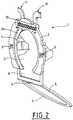
- La
Figure 2 représente un deuxième mode de réalisation d'une bague support d'informations 1 pour un ensemble robinet 20 / récipient de gaz 40 selon la présente invention, lequel est quasi identique au premier mode de laFigure 1 , à l'exception du fait que : - la fenêtre de lecture 8 n'est pas totalement délimitée par rapport à la première ouverture 3, c'est-à-dire que la fenêtre 8 s'ouvre dans la première ouverture 3, pour s'adapter à la géométrie du robinet.
- le corps principal 2 comporte, en partie supérieure, deux expansions ou bras 11 recourbés servant à renforcer le maintien avec le capotage de protection 30.
- En outre, sur la
Figure 2 , l'arceau 4 est représenté en une position pivotée par rapport au corps principal 2 de la bague 1, alors que sur laFigure 1 , il est en position de repos, c'est-à-dire non pivoté. - La
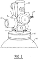
Figure 3 schématise la bague support d'informations 1 de laFigure 1 agencée sur un bloc robinet 20, plus simplement appelé robinet, venant se fixer par vissage, via sa base filetée 21, au niveau du col 41 d'un récipient de gaz 40, à savoir une bouteille gaz, c'est-à-dire dans l'orifice de sortie taraudé dudit récipient 40. - Le robinet 20 peut être du type avec ou sans détendeur intégré et comprend les différents organes et éléments classiques d'un tel robinet 40, notamment un raccord de remplissage 22, un raccord de sortie 23 de gaz, un volant ou levier de manoeuvre contrôlant la sortie du gaz, un manomètre....
- Comme on le voit, la bague support d'informations 1 est retenue sur le robinet 40 grâce aux première et deuxième ouvertures 3, 5 du corps principal 2 de bague et de l'arceau 4, respectivement, et y est maintenu en position grâce aux deux parois 7 en saillie et les bras 11.
- Plus précisément, la base 21 du robinet 20 traverse la deuxième ouverture 5 délimitée par l'arceau 4, c'est-à-dire que l'arceau 4 vient ceinturer la base 21 du robinet qui a typiquement une forme de cône fileté, alors que le raccord de remplissage 22 traverse la première ouverture 3 située au centre du corps principal 2 de bague, c'est-à-dire que le corps principal 2 de bague vient ceinturer le raccord de remplissage 22 du robinet 20. Les deux parois 7 en saillie viennent quant à elles prendre le raccord de remplissage 22 en sandwich en venant appuyer latéralement de part et d'autre dudit raccord de remplissage 22.
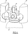
- La
Figure 4 est analogue à laFigure 3 mais montre en plus un capotage de protection 30 formé de deux demi-coques venant englober l'ensemble du robinet 20 et le col 41 de la bouteille 40 de manière à protéger ces éléments. Le capotage de protection 30 peut être en polymère ou en métal. - Les
Figures 5A à 5D illustrent la séquence de montage de la bague support d'informations 1 de laFigure 1 sur le robinet 20 desFigures 3 ou4 , avant montage de ce dernier sur un récipient de gaz 40, à savoir une bouteille de gaz. - Comme on le voit, on commence par insérer le raccord de remplissage 22 dans la première ouverture 3 située au centre du corps principal 2 de bague de la bague support d'informations 1 selon la présente invention, ce qui permet alors aux deux parois 7 en saillie de prendre le raccord de remplissage 22 en sandwich (
Fig. 5A et 5B ). - Ensuite, on opère un pivotement de l'arceau 4 par rapport au corps principal 2 de bague de la bague support d'informations 1 selon la présente invention, lequel arceau 4 se plie alors le long de la charnière 6 avec zone de pli préformée en venant encercler la base 21 conique du robinet 20 puisque la base 21 du robinet 20 traverse alors la deuxième ouverture 5 délimitée par l'arceau 4 (
Fig. 5C ). La charnière 6 et l'arceau 4 constituent donc un cerclage autour de la base 21 en forme de cône filetée du robinet 20. - Enfin, on procède à la fixation du robinet 20 équipé de la bague support d'informations 1 selon la présente invention, sur le col 41 du récipient par vissage de la base 21 filetée du robinet 20 au sein de l'orifice de sortie taraudé traversant ledit col 41 et communiquant fluidiquement avec le volume interne du récipient 40.
- Optionnellement, un capotage de protection 30 peut être ensuite fixé autour du robinet 20 (cf.
Fig. 4 ). - La
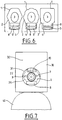
Figure 6 illustre trois modes de réalisation d'une bague support d'informations 1 pour un ensemble bloc robinet/récipient de gaz selon la présente invention se différenciant les uns des autres par la forme générale du corps principal 2 de bague, à savoir un disque sensiblement hexagonal (à gauche), carré (à droite) ou quasi-circulaire avec des encoches/crans sur sa périphérie externe (au centre). Bien entendu, d'autres formes sont envisageables, notamment un disque circulaire. - La
Figure 7 montre un récipient de gaz 40 équipé d'un bloc robinet protégé par un capotage 30 de protection comprenant une découpe 31 pratiquée dans sa paroi périphérique 32 laissant apparaître un support d'informations 1 selon la présente invention agencée autour du raccord de remplissage 22 du bloc robinet. - On voit que la découpe avant 31 permet à l'utilisateur (c'est-à-dire opérateurs et personnes autorisées) d'avoir facilement accès aux informations situées dans les zones de marquage 9, 10 portées par le support d'informations 1 selon la présente invention, ainsi qu'à celles figurant dans/sous la fenêtre de lecture 8, et ce, malgré la présence du capotage 30. En d'autres termes, il n'est nul besoin de démonter tout le capotage 30 pour avoir accès aux informations légales et/ou réglementaires portées par la bague 1 de l'invention.
- Le support d'informations 1 vient donc s'emprisonner entre le capotage de protection 30 et le robinet 20.
- L'ensemble robinet/récipient de gaz/support d'informations selon la présente invention peut contenir, stocker et/ou fournir un gaz ou mélange gazeux, en particulier un gaz ou mélange gazeux médical ou industriel.
Claims (12)
- Ensemble de distribution de gaz comprenant :- un récipient de gaz (40) équipé d'un bloc robinet (20) comprenant une base filetée (21) et au moins un raccord (22), et- une bague support d'informations (1) agencée autour du bloc robinet (20), ladite bague support d'informations (1) comprenant un corps principal (2) de bague traversé par une première ouverture (3), et un arceau (4) fixé solidairement et articulé en pivotement par rapport audit corps principal (2), ledit arceau (4) définissant une seconde ouverture (5),caractérisé en ce que :. la base filetée (21) du bloc robinet (20) traverse la seconde ouverture (5) de l'arceau (4) de la bague support d'informations (1), et. la première ouverture (3) du corps principal (2) de la bague support d'informations (1) est traversée par le raccord (22) du bloc robinet (20).
- Ensemble de distribution de gaz selon la revendication précédente, caractérisé en ce que le corps principal (2) de la bague (1) a une forme de bague aplatie présentant une face avant (2a) et une face arrière (2b).
- Ensemble de distribution de gaz selon l'une des revendications précédentes, caractérisé en ce que l'arceau (4) de la bague (1) est articulé en pivotement le long d'au moins une charnière (6) au niveau de laquelle l'arceau (4) vient se solidariser audit corps principal (2).
- Ensemble de distribution de gaz selon l'une des revendications précédentes, caractérisé en ce que le corps principal (2) de la bague (1) comprend deux parois (7) en saillie se faisant face et se projetant en éloignement par rapport audit corps principal (2), de préférence par rapport à la face arrière (2b).
- Ensemble de distribution de gaz selon l'une des revendications précédentes, caractérisé en ce que le corps principal (2) de la bague (1) comprend une fenêtre de lecture (8) située entre la première ouverture (3) et ladite au moins une charnière (6).
- Ensemble de distribution de gaz selon l'une des revendications précédentes, caractérisé en ce que le corps principal (2) de la bague (1) est conformé pour présenter au moins une zone de marquage (9, 10), de préférence ladite au moins une zone de marquage (9, 10) est portée par la face avant (2a).
- Ensemble de distribution de gaz selon l'une des revendications précédentes, caractérisée en ce que la bague (1) est formée de plastique ou de métal.
- Ensemble de distribution de gaz selon l'une des revendications précédentes, caractérisé en ce qu'il comprend un capotage de protection (30) agencé autour du bloc robinet (20) et de la bague support d'informations (1).
- Ensemble selon l'une des revendications précédentes, caractérisé en ce que le raccord (22) est un raccord de remplissage.
- Ensemble selon l'une des revendications précédentes, caractérisé en ce qu'il comprend un capotage de protection (30) agencé autour du bloc robinet (20) et de la bague support d'informations (1).
- Ensemble selon l'une des revendications précédentes, caractérisé en ce que le capotage de protection (30) comprend une découpe (31) laissant apparaître le support d'informations (1).
- Utilisation d'un ensemble de distribution de gaz comprenant un récipient de gaz (40) selon l'une des revendications 1 à 9, équipé d'un bloc robinet (20) et d'une bague support d'informations (1) agencée autour du bloc robinet (20), pour contenir, stocker et/ou fournir un gaz.
Applications Claiming Priority (1)
| Application Number | Priority Date | Filing Date | Title |
|---|---|---|---|
| FR1652858A FR3049679B1 (fr) | 2016-04-01 | 2016-04-01 | Bague support d’informations pour robinet de recipient de gaz |
Publications (1)
| Publication Number | Publication Date |
|---|---|
| EP3225902A1 true EP3225902A1 (fr) | 2017-10-04 |
Family
ID=56684007
Family Applications (1)
| Application Number | Title | Priority Date | Filing Date |
|---|---|---|---|
| EP17157105.2A Withdrawn EP3225902A1 (fr) | 2016-04-01 | 2017-02-21 | Ensemble de distribution de gaz comprenant un récipient de gaz équipé d'un bloc robinet et d'une bague support d'informations |
Country Status (2)
| Country | Link |
|---|---|
| EP (1) | EP3225902A1 (fr) |
| FR (1) | FR3049679B1 (fr) |
Citations (6)
| Publication number | Priority date | Publication date | Assignee | Title |
|---|---|---|---|---|
| EP0515184A1 (fr) * | 1991-05-24 | 1992-11-25 | Safe T Seal Limited | Dispositif de fermeture à sceau, inviolable pour des bouteilles à gaz |
| US5249380A (en) | 1991-08-28 | 1993-10-05 | Jacob Fast | Identification tag holder for gas cylinder |
| US5555655A (en) * | 1994-09-26 | 1996-09-17 | Aga Ab | Identification device for a container |
| EP1599850A1 (fr) * | 2003-03-04 | 2005-11-30 | The BOC Group plc | Etiquette |
| US20080230509A1 (en) * | 2005-10-10 | 2008-09-25 | Itw New Zealand Limited | Identification Attachments |
| US20130334236A1 (en) * | 2011-03-01 | 2013-12-19 | Joachim Gerstel | Security Device for Gas Cylinders |
-
2016
- 2016-04-01 FR FR1652858A patent/FR3049679B1/fr not_active Expired - Fee Related
-
2017
- 2017-02-21 EP EP17157105.2A patent/EP3225902A1/fr not_active Withdrawn
Patent Citations (6)
| Publication number | Priority date | Publication date | Assignee | Title |
|---|---|---|---|---|
| EP0515184A1 (fr) * | 1991-05-24 | 1992-11-25 | Safe T Seal Limited | Dispositif de fermeture à sceau, inviolable pour des bouteilles à gaz |
| US5249380A (en) | 1991-08-28 | 1993-10-05 | Jacob Fast | Identification tag holder for gas cylinder |
| US5555655A (en) * | 1994-09-26 | 1996-09-17 | Aga Ab | Identification device for a container |
| EP1599850A1 (fr) * | 2003-03-04 | 2005-11-30 | The BOC Group plc | Etiquette |
| US20080230509A1 (en) * | 2005-10-10 | 2008-09-25 | Itw New Zealand Limited | Identification Attachments |
| US20130334236A1 (en) * | 2011-03-01 | 2013-12-19 | Joachim Gerstel | Security Device for Gas Cylinders |
Also Published As
| Publication number | Publication date |
|---|---|
| FR3049679B1 (fr) | 2018-08-10 |
| FR3049679A1 (fr) | 2017-10-06 |
Similar Documents
| Publication | Publication Date | Title |
|---|---|---|
| EP1236492B1 (fr) | Carter étanche à fermeture quart de tour | |
| EP0629812B1 (fr) | Chapeau de bouteille de gaz | |
| FR2792622A1 (fr) | Distributeur de produit fluide a poche souple | |
| EP3643958B1 (fr) | Ensemble comprenant un capotage de protection et une bouteille de gaz avec un dispositif indicateur de pression ou d'autonomie en position haute | |
| CA2884483A1 (fr) | Ensemble de distribution de gaz avec organe de commande rotatif protege par un rebord en saillie portant une fenetre de lecture | |
| EP2873908B1 (fr) | Protecteur universel pour bouteille à gaz | |
| FR3018581A1 (fr) | Capotage avec rebord de protection de l'organe de commande rotatif d'un bloc robinet de recipient de gaz | |
| EP3193072B1 (fr) | Protecteur universel pour bouteille de gaz | |
| EP2261547A2 (fr) | Chapeau de protection pour récipient de fluide | |
| FR3049679A1 (fr) | Bague support d’informations pour robinet de recipient de gaz | |
| FR3052846A1 (fr) | Capotage de protection avec systeme d'accrochage pivotant a butee d'arret pour recipient de gaz | |
| EP3267092B1 (fr) | Ensemble de distribution de gaz comprenant un capotage agencé autour d'un bloc robinet équipant un récipient de gaz | |
| EP3059144B1 (fr) | Ensemble structurel de véhicule comprenant un corps principal et un élément d'obturation ancré dans ledit corps principal et apte à être démonté | |
| FR3038213A1 (fr) | Boitier cosmetique de type poudrier | |
| EP1405796B1 (fr) | Dispositif de distribution de fluide | |
| FR2927980A1 (fr) | Dispositif d'obturation de raccord de sortie de robinet de gaz. | |
| FR3054416A1 (fr) | Dispositif de conditionnement pour produit cosmetique | |
| FR3052845A1 (fr) | Capotage de protection de recipient de gaz a ouverture recouverte par paroi amovible | |
| CA2553319A1 (fr) | Dispositif de securisation de tubes | |
| FR3160337A1 (fr) | Bride de cellule pour porte étanche double à canal de pressurisation | |
| EP2981159B1 (fr) | Boîtier électronique présentant un socle | |
| WO2021018746A1 (fr) | Bouchon pour la fermeture d'un réceptacle ainsi qu'un ensemble comprenant ledit bouchon | |
| EP1939043A1 (fr) | Ensemble de support d'accessoires nomades pour véhicule automobile | |
| WO2021018528A1 (fr) | Bouchon pour la fermeture d'un receptacle ainsi qu'un ensemble comprenant ledit bouchon | |
| FR3054637A1 (fr) | Capotage de protection pour recipient de gaz a poignee de portage munie d’une etiquette electronique |
Legal Events
| Date | Code | Title | Description |
|---|---|---|---|
| PUAI | Public reference made under article 153(3) epc to a published international application that has entered the european phase |
Free format text: ORIGINAL CODE: 0009012 |
|
| AK | Designated contracting states |
Kind code of ref document: A1 Designated state(s): AL AT BE BG CH CY CZ DE DK EE ES FI FR GB GR HR HU IE IS IT LI LT LU LV MC MK MT NL NO PL PT RO RS SE SI SK SM TR |
|
| AX | Request for extension of the european patent |
Extension state: BA ME |
|
| 17P | Request for examination filed |
Effective date: 20180404 |
|
| RBV | Designated contracting states (corrected) |
Designated state(s): AL AT BE BG CH CY CZ DE DK EE ES FI FR GB GR HR HU IE IS IT LI LT LU LV MC MK MT NL NO PL PT RO RS SE SI SK SM TR |
|
| STAA | Information on the status of an ep patent application or granted ep patent |
Free format text: STATUS: THE APPLICATION HAS BEEN WITHDRAWN |
|
| 18W | Application withdrawn |
Effective date: 20191021 |