EP3225853A1 - Fan motor - Google Patents
Fan motor Download PDFInfo
- Publication number
- EP3225853A1 EP3225853A1 EP17160338.4A EP17160338A EP3225853A1 EP 3225853 A1 EP3225853 A1 EP 3225853A1 EP 17160338 A EP17160338 A EP 17160338A EP 3225853 A1 EP3225853 A1 EP 3225853A1
- Authority
- EP
- European Patent Office
- Prior art keywords
- fan motor
- bottom plate
- tubular
- thermosetting resin
- motor according
- Prior art date
- Legal status (The legal status is an assumption and is not a legal conclusion. Google has not performed a legal analysis and makes no representation as to the accuracy of the status listed.)
- Withdrawn
Links
- 229920005989 resin Polymers 0.000 claims abstract description 48
- 239000011347 resin Substances 0.000 claims abstract description 48
- 229920001187 thermosetting polymer Polymers 0.000 claims abstract description 45
- WABPQHHGFIMREM-UHFFFAOYSA-N lead(0) Chemical group [Pb] WABPQHHGFIMREM-UHFFFAOYSA-N 0.000 claims abstract description 17
- 230000000873 masking effect Effects 0.000 description 12
- 238000000034 method Methods 0.000 description 6
- 230000008569 process Effects 0.000 description 5
- 239000007788 liquid Substances 0.000 description 3
- 230000004048 modification Effects 0.000 description 3
- 238000012986 modification Methods 0.000 description 3
- 238000001816 cooling Methods 0.000 description 2
- 239000007789 gas Substances 0.000 description 2
- XLYOFNOQVPJJNP-UHFFFAOYSA-N water Substances O XLYOFNOQVPJJNP-UHFFFAOYSA-N 0.000 description 2
- 230000009471 action Effects 0.000 description 1
- 239000000853 adhesive Substances 0.000 description 1
- 230000001070 adhesive effect Effects 0.000 description 1
- 239000002390 adhesive tape Substances 0.000 description 1
- 230000004888 barrier function Effects 0.000 description 1
- 239000003795 chemical substances by application Substances 0.000 description 1
- 230000005484 gravity Effects 0.000 description 1
- 238000001746 injection moulding Methods 0.000 description 1
- 239000010687 lubricating oil Substances 0.000 description 1
- 239000000463 material Substances 0.000 description 1
- 230000007246 mechanism Effects 0.000 description 1
- 239000002184 metal Substances 0.000 description 1
- 229920001225 polyester resin Polymers 0.000 description 1
- 239000004645 polyester resin Substances 0.000 description 1
- 238000002360 preparation method Methods 0.000 description 1
- 230000000630 rising effect Effects 0.000 description 1
- 238000007789 sealing Methods 0.000 description 1
- 230000007480 spreading Effects 0.000 description 1
- 238000004078 waterproofing Methods 0.000 description 1
Images




Classifications
-
- F—MECHANICAL ENGINEERING; LIGHTING; HEATING; WEAPONS; BLASTING
- F04—POSITIVE - DISPLACEMENT MACHINES FOR LIQUIDS; PUMPS FOR LIQUIDS OR ELASTIC FLUIDS
- F04D—NON-POSITIVE-DISPLACEMENT PUMPS
- F04D25/00—Pumping installations or systems
- F04D25/02—Units comprising pumps and their driving means
- F04D25/06—Units comprising pumps and their driving means the pump being electrically driven
- F04D25/0693—Details or arrangements of the wiring
-
- F—MECHANICAL ENGINEERING; LIGHTING; HEATING; WEAPONS; BLASTING
- F04—POSITIVE - DISPLACEMENT MACHINES FOR LIQUIDS; PUMPS FOR LIQUIDS OR ELASTIC FLUIDS
- F04D—NON-POSITIVE-DISPLACEMENT PUMPS
- F04D19/00—Axial-flow pumps
- F04D19/002—Axial flow fans
-
- F—MECHANICAL ENGINEERING; LIGHTING; HEATING; WEAPONS; BLASTING
- F04—POSITIVE - DISPLACEMENT MACHINES FOR LIQUIDS; PUMPS FOR LIQUIDS OR ELASTIC FLUIDS
- F04D—NON-POSITIVE-DISPLACEMENT PUMPS
- F04D29/00—Details, component parts, or accessories
- F04D29/02—Selection of particular materials
- F04D29/023—Selection of particular materials especially adapted for elastic fluid pumps
-
- F—MECHANICAL ENGINEERING; LIGHTING; HEATING; WEAPONS; BLASTING
- F04—POSITIVE - DISPLACEMENT MACHINES FOR LIQUIDS; PUMPS FOR LIQUIDS OR ELASTIC FLUIDS
- F04D—NON-POSITIVE-DISPLACEMENT PUMPS
- F04D29/00—Details, component parts, or accessories
- F04D29/08—Sealings
- F04D29/083—Sealings especially adapted for elastic fluid pumps
-
- F—MECHANICAL ENGINEERING; LIGHTING; HEATING; WEAPONS; BLASTING
- F04—POSITIVE - DISPLACEMENT MACHINES FOR LIQUIDS; PUMPS FOR LIQUIDS OR ELASTIC FLUIDS
- F04D—NON-POSITIVE-DISPLACEMENT PUMPS
- F04D29/00—Details, component parts, or accessories
- F04D29/26—Rotors specially for elastic fluids
- F04D29/32—Rotors specially for elastic fluids for axial flow pumps
- F04D29/325—Rotors specially for elastic fluids for axial flow pumps for axial flow fans
-
- F—MECHANICAL ENGINEERING; LIGHTING; HEATING; WEAPONS; BLASTING
- F04—POSITIVE - DISPLACEMENT MACHINES FOR LIQUIDS; PUMPS FOR LIQUIDS OR ELASTIC FLUIDS
- F04D—NON-POSITIVE-DISPLACEMENT PUMPS
- F04D29/00—Details, component parts, or accessories
- F04D29/26—Rotors specially for elastic fluids
- F04D29/32—Rotors specially for elastic fluids for axial flow pumps
- F04D29/38—Blades
-
- F—MECHANICAL ENGINEERING; LIGHTING; HEATING; WEAPONS; BLASTING
- F04—POSITIVE - DISPLACEMENT MACHINES FOR LIQUIDS; PUMPS FOR LIQUIDS OR ELASTIC FLUIDS
- F04D—NON-POSITIVE-DISPLACEMENT PUMPS
- F04D29/00—Details, component parts, or accessories
- F04D29/40—Casings; Connections of working fluid
- F04D29/52—Casings; Connections of working fluid for axial pumps
- F04D29/522—Casings; Connections of working fluid for axial pumps especially adapted for elastic fluid pumps
-
- F—MECHANICAL ENGINEERING; LIGHTING; HEATING; WEAPONS; BLASTING
- F04—POSITIVE - DISPLACEMENT MACHINES FOR LIQUIDS; PUMPS FOR LIQUIDS OR ELASTIC FLUIDS
- F04D—NON-POSITIVE-DISPLACEMENT PUMPS
- F04D29/00—Details, component parts, or accessories
- F04D29/60—Mounting; Assembling; Disassembling
- F04D29/64—Mounting; Assembling; Disassembling of axial pumps
- F04D29/644—Mounting; Assembling; Disassembling of axial pumps especially adapted for elastic fluid pumps
- F04D29/646—Mounting or removal of fans
-
- F—MECHANICAL ENGINEERING; LIGHTING; HEATING; WEAPONS; BLASTING
- F05—INDEXING SCHEMES RELATING TO ENGINES OR PUMPS IN VARIOUS SUBCLASSES OF CLASSES F01-F04
- F05D—INDEXING SCHEME FOR ASPECTS RELATING TO NON-POSITIVE-DISPLACEMENT MACHINES OR ENGINES, GAS-TURBINES OR JET-PROPULSION PLANTS
- F05D2230/00—Manufacture
- F05D2230/40—Heat treatment
- F05D2230/41—Hardening; Annealing
-
- F—MECHANICAL ENGINEERING; LIGHTING; HEATING; WEAPONS; BLASTING
- F05—INDEXING SCHEMES RELATING TO ENGINES OR PUMPS IN VARIOUS SUBCLASSES OF CLASSES F01-F04
- F05D—INDEXING SCHEME FOR ASPECTS RELATING TO NON-POSITIVE-DISPLACEMENT MACHINES OR ENGINES, GAS-TURBINES OR JET-PROPULSION PLANTS
- F05D2250/00—Geometry
- F05D2250/20—Three-dimensional
- F05D2250/29—Three-dimensional machined; miscellaneous
- F05D2250/294—Three-dimensional machined; miscellaneous grooved
-
- F—MECHANICAL ENGINEERING; LIGHTING; HEATING; WEAPONS; BLASTING
- F05—INDEXING SCHEMES RELATING TO ENGINES OR PUMPS IN VARIOUS SUBCLASSES OF CLASSES F01-F04
- F05D—INDEXING SCHEME FOR ASPECTS RELATING TO NON-POSITIVE-DISPLACEMENT MACHINES OR ENGINES, GAS-TURBINES OR JET-PROPULSION PLANTS
- F05D2300/00—Materials; Properties thereof
- F05D2300/40—Organic materials
- F05D2300/44—Resins
-
- H—ELECTRICITY
- H01—ELECTRIC ELEMENTS
- H01B—CABLES; CONDUCTORS; INSULATORS; SELECTION OF MATERIALS FOR THEIR CONDUCTIVE, INSULATING OR DIELECTRIC PROPERTIES
- H01B7/00—Insulated conductors or cables characterised by their form
- H01B7/02—Disposition of insulation
Definitions
- the present invention relates to a fan motor.
- Axial fan motors arranged to produce axial air flows by rotating impellers using driving forces of motors have been known.
- the axial fan motors are, for example, installed in household electrical appliances, office automation appliances, transportation equipment, and so on, and are used for the purposes of cooling electronic components, circulating gases in device cases, and so on.
- fan motors are sometimes used for circulating gases in server rooms in which a large number of electronic devices are installed.
- a known fan motor is described in, for example, JP-A H11-089155 .
- the fan motor described in JP-A H11-089155 includes several spokes extending from an outer circumferential portion of a housing to a central portion thereof, and a circuit portion and so on in the central portion are held by the spokes.
- a waterproofing agent is arranged in an area through which lead wires are drawn out from the circuit portion to one of the spokes to achieve improved waterproof performance.
- thermosetting resin for the purpose of improving waterproof performance of a fan motor, a process of pouring a thermosetting resin on an area through which a lead wire is drawn out or into a space surrounding the lead wire and curing the thermosetting resin is often performed.
- a leakage of the thermosetting resin may sometimes occur. If a leakage of the thermosetting resin occurs, a device to which the fan motor is attached may be affected, and therefore, the thermosetting resin must be removed and the process must be performed again.
- a leakage of the thermosetting resin might result in an unwanted external appearance of the fan motor.
- an adhesive tape for example, a masking tape
- a masking tape is often stuck to a rib or an outer frame of the fan motor, for example, to prevent a leakage of the thermosetting resin.
- a fan motor includes a motor including a stationary portion and a rotating portion arranged to rotate about a rotation axis extending in a vertical direction; an impeller including a plurality of blades, and arranged to rotate together with the rotating portion; a housing arranged to house the motor and the impeller therein; and a lead wire electrically connected to the motor, and arranged to extend outwardly of the housing.
- the housing includes a tubular portion being tubular, and arranged to extend from an inlet side to an outlet side along the rotation axis, and house at least a portion of the impeller therein; a bottom plate portion fixed below the motor and radially inside of the tubular portion; and a support portion arranged to extend from at least a portion of the tubular portion toward the bottom plate portion, and joined to at least a portion of the bottom plate portion.
- the support portion includes a groove portion recessed upward.
- the tubular portion includes a cut portion defined at a portion thereof continuous with the groove portion. The lead wire is drawn out of the housing through the groove portion and the cut portion. At least one of the groove portion and the cut portion has a thermosetting resin arranged therein.
- thermosetting resin In the fan motor according to the above preferred embodiment of the present invention, an area in which the thermosetting resin is arranged can be easily sealed. This contributes to preventing a leakage of the thermosetting resin and an unwanted external appearance of the fan motor.
- FIG. 1 is a vertical sectional view of a fan motor 1 according to a preferred embodiment of the present invention.
- the fan motor 1 is used, for example, as an apparatus that supplies a cooling air flow to a household electrical appliance, such as a refrigerator, or an interior of a room, such as a server room, in which a plurality of electronic devices are installed.
- the fan motor 1 may be used singly, or alternatively, a plurality of fan motors 1 may be used at the same time in combination.
- a plurality of fan motors 1 may be installed in a single server room, and these fan motors 1 may be driven at the same time.
- the fan motor 1 includes a motor 2, an impeller 3, and a housing 4.
- the fan motor 1 is an axial fan arranged to produce a downward air flow along a rotation axis 9. Once the fan motor 1 is driven, air is taken in from the upper side of the fan motor 1, i.e., from the inlet side, and the air is sent to the lower side of the fan motor 1, i.e., to the outlet side, through a wind channel 10.
- the motor 2 includes a stationary portion 21 and a rotating portion 22.
- the rotating portion 22 is supported to be rotatable with respect to the stationary portion 21.
- the rotating portion 22 is arranged to rotate about the rotation axis 9, which extends in a vertical direction.
- the stationary portion 21 includes a base portion 211, a stator 212, and a bearing member 213.
- the base portion 211 is arranged to extend along the rotation axis 9 to assume a cylindrical shape.
- the stator 212 is an armature fixed to an outer circumferential surface of the base portion 211.
- the stator 212 includes a stator core 51 and a plurality of coils 52.
- the stator core 51 includes a plurality of teeth arranged to extend radially.
- Each of the coils 52 is defined by a conducting wire wound around a separate one of the teeth.
- the bearing member 213 is a cylindrical member arranged radially inside of the base portion 211.
- the bearing member 213 is fixed to an inner circumferential surface of the base portion 211 through, for example, an adhesive.
- a lower portion of a shaft 221, which will be described below, is inserted radially inside of the bearing member 213.
- a lubricating oil is arranged between an inner circumferential surface of the bearing member 213 and an outer circumferential surface of the shaft 221.
- the shaft 221 is thus supported to be rotatable with respect to the stationary portion 21.
- the motor 2 may alternatively include a bearing mechanism of another type, such as, for example, a ball bearing, in place of the bearing member 213.
- the rotating portion 22 includes the shaft 221, a rotor holder 222, and a magnet 223.
- the shaft 221 is a columnar member arranged to extend along the rotation axis 9.
- the shaft 221 is rotatably supported by the base portion 211 through the bearing member 213.
- An upper end portion of the shaft 221 is arranged to project upward above the bearing member 213. While the motor 2 is running, the shaft 221 rotates about the rotation axis 9.
- the rotor holder 222 is a member in the shape of a covered cylinder, including a disk-shaped rotor cover portion 53 arranged to extend substantially perpendicularly to the rotation axis 9, and a rotor tubular portion 54 arranged to extend from the rotor cover portion 53 to the outlet side.
- a metal or a resin, for example, is used as a material of the rotor holder 222.
- a central portion of the rotor cover portion 53 is fixed to the upper end portion of the shaft 221.
- the rotor holder 222 is thus arranged to rotate together with the shaft 221.
- the rotor cover portion 53 is arranged on the inlet side of the stationary portion 21.
- the rotor tubular portion 54 is arranged radially outside of the stator 212.
- the impeller 3 includes a plurality of blades. An inner end portion of each blade is joined to the rotor tubular portion 54. That is, each blade is arranged to extend radially outward from a junction of the blade with the rotor tubular portion 54.
- the impeller 3 is arranged to rotate together with the shaft 221 and the rotor holder 222 of the rotating portion 22.
- the blades are arranged at substantially regular intervals in a circumferential direction. Note that the number of blades is not limited to particular values.
- the housing 4 is a case arranged to house the motor 2 and the impeller 3 therein.
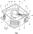
- FIG. 2 is a perspective view of the housing 4 as viewed obliquely from below.
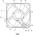
- FIG. 3 is a bottom view of the housing 4.
- the housing 4 includes a tubular portion 61, a bottom plate portion 62, and a plurality of support portions (ribs) 63.
- the tubular portion 61 is tubular and is arranged to extend from the inlet side (i.e., the upper side) to the outlet side (i.e., the lower side) along the rotation axis 9.
- the tubular portion 61 is arranged to extend radially outside of the impeller 3 to substantially assume a cylindrical shape.
- the tubular portion 61 is arranged to house at least a portion of the impeller 3 therein. That is, the tubular portion 61 is arranged in an annular shape radially outside of the impeller 3 to surround the impeller 3.
- the housing 4 includes the bottom plate portion 62, which is fixed below the motor 2 and radially inside of the tubular portion 61.
- the bottom plate portion 62 is arranged radially inside of the tubular portion 61 and below the stator 212.
- the bottom plate portion 62 includes a disk-shaped portion 621 and a circumferential wall portion 622.
- the disk-shaped portion 621 is arranged to extend substantially perpendicularly to the rotation axis 9.
- the circumferential wall portion 622 is arranged to extend upward from an outer circumferential portion of the disk-shaped portion 621 to assume a tubular shape.
- a lower end portion of the base portion 211 of the motor 2 is fixed to the disk-shaped portion 621.
- the base portion 211 and the bottom plate portion 62 are defined by a single continuous monolithic member. Note, however, that the base portion 211 and the bottom plate portion 62 may alternatively be defined by separate members.
- the housing 4 includes the plurality of support portions 63.
- Each support portion 63 is arranged to extend from at least a portion of an inner surface of the tubular portion 61 toward the bottom plate portion 62, and is joined to at least a portion of the bottom plate portion 62.
- the stationary portion 21 of the motor 2 is thus positioned with respect to the housing 4.
- the number of support portions 63 is four. Note, however, that the number of support portions 63 may alternatively be one, two, three, or more than four.
- the support portions 63 are arranged at regular intervals in the circumferential direction around the bottom plate portion 62. Each support portion 63 is arranged to extend in a straight line perpendicularly to the axial direction. Referring to FIG. 2 , each support portion 63 according to the present preferred embodiment is arranged to extend along a tangent to a circular outer circumference of the bottom plate portion 62. Note, however, that each support portion 63 may not necessarily be arranged to extend along the tangent to the outer circumference of the bottom plate portion 62. Each support portion 63 may alternatively be arranged to extend in a radial direction.
- each support portion 63 extends from the circular outer circumference of the bottom plate portion 62 to an inner circumference of the tubular portion 61 in the present preferred embodiment.
- the bottom plate portion 62 and each support portion 63 are smoothly joined to each other, and are defined integrally with each other.
- each support portion 63 and the tubular portion 61 are smoothly joined to each other, and are defined integrally with each other.
- the tubular portion 61, the bottom plate portion 62, and the support portions 63 are defined in one piece by a resin injection molding process. Note, however, that any two or more of the tubular portion 61, the bottom plate portion 62, and the support portions 63 may alternatively be defined by separate members.
- the housing 4 includes a plurality of flange portions 73 each of which is arranged to project radially outward.
- flange portions 73 are arranged at regular intervals in the circumferential direction.
- the flange portions 73 are fixed to a frame of a household electrical appliance or the like through screws.
- the flange portions 73 may not necessarily be provided in the housing 4.
- the flange portions 73 may alternatively be provided at only one of the upper and lower ends of the tubular portion 61.
- Lead wires 60 are shown in FIG. 2 .
- At least one of the four support portions 63 is wider than the other support portions 63, and includes a groove portion 81 recessed upward (i.e., to the side on which the motor 2 is disposed).
- the groove portion 81 is arranged to extend along a longitudinal direction of the support portion 63.
- a cut portion 82 is defined at a portion of the tubular portion 61 which is continuous with the groove portion 81, more specifically, a portion of the tubular portion 61 which is continuous with the groove portion 81 on a radially outward extension of the support portion 63 along the longitudinal direction thereof.
- the cut portion 82 is defined by cutting a portion of the tubular portion 61 substantially in a radial direction. Note that this cutting is done slightly obliquely with respect to the radial direction, in a direction parallel to the longitudinal direction of the support portion 63. Further, the tubular portion 61 includes restricting portions 67 in the vicinity of the cut portion 82. A radially outer surface of each restricting portion 67 is arranged to have a sufficient area to allow a masking tape 30 to be stuck thereto. The restricting portions 67 are arranged to extend in the axial direction on both circumferential sides of the cut portion 82. Each restricting portion 67 is arranged to have an axial dimension greater than that of each flange portion 73, allowing the masking tape 30 to be easily stuck thereto.
- each of the support portions 63 is smoothly and continuously joined to each of at least a portion of the lower surface of the tubular portion 61 and at least a portion of a lower surface of the bottom plate portion 62 in a radial direction. This makes it possible to easily cover at least a portion of the lower surface of each support portion 63, at least a portion of the lower surface of the tubular portion 61, and at least a portion of the lower surface of the bottom plate portion 62 with the masking tape 30 without a gap. A leakage of the thermosetting resin 20, which will be described below, can thus be prevented.
- the bottom plate portion 62 includes a recessed portion 83 defined in at least a portion of the lower surface thereof.
- a nameplate or the like is typically installed in the recessed portion 83.
- the recessed portion 83 prevents a shoulder from being defined due to the thickness of the nameplate when the nameplate is stuck to the bottom plate portion 62.
- an end portion 623 of the bottom plate portion 62 at a junction of the bottom plate portion 62 with the support portion 63 including the groove portion 81 is spaced from the recessed portion 83 so as not to overlap with the recessed portion 83. This spacing facilitates an operation of sticking the masking tape 30 to the bottom plate portion 62 in preparation for pouring of the thermosetting resin 20.
- an opening portion 64 is defined in the vicinity of the junction of the bottom plate portion 62 with the support portion 63.
- a circuit board 65 which is arranged in a lower portion of the motor 2, is exposed outwardly through the opening portion 64 on the lower side of the fan motor 1.
- Each lead wire 60 is electrically connected to the circuit board 65 of the motor 2.
- the lead wire 60 is arranged to pass through the opening portion 64 on the axially lower side, be accommodated in the groove portion 81 of the support portion 63, and extend radially outward along the groove portion 81.
- the lead wire 60 is arranged to pass through the groove portion 81 and the cut portion 82, and is drawn out of the housing 4, that is, out of the fan motor 1.
- the groove portion 81 is arranged to have sufficient depth and width to allow the lead wires 60 to be accommodated therein.
- FIG. 4 is a sectional view of the support portion 63 taken along line X-X in FIG. 3 .
- the support portion 63 includes a plurality of projecting portions 68.
- Each of the projecting portions 68 is arranged to project in a direction that crosses the longitudinal direction of the support portion 63 in the groove portion 81.
- Each lead wire 60 is accommodated in a space 682 to the side of the projecting portions 68 in the groove portion 81. That is, the projecting portions 68 are arranged to hold the lead wires 60 accommodated in the groove portion 81 at a plurality of positions to prevent the lead wires 60 from protruding from a surface of the thermosetting resin 20 and downward out of the groove portion 81.
- the support portion 63 includes a tapered surface 631 which is angled with respect to both the axial and circumferential directions.
- the direction of an air flow passing through the wind channel 10 can thus be adjusted to achieve improved characteristics of the fan motor 1. Moreover, noise caused by rotation of the fan motor 1 can thus be minimized.
- thermosetting resin 20 is arranged to extend from a radially innermost end of the groove portion 81 in the vicinity of a junction of the groove portion 81 with the bottom plate portion 62 to a position radially outward of a projecting portion 681, which is the radially outermost one of the projecting portions 68, in the vicinity of a junction of the groove portion 81 with the tubular portion 61.
- the projecting portion 681 which is the radially outermost one of the projecting portions 68, is arranged to have the greatest axial dimension of all the projecting portions 68. Radially outward spreading of the thermosetting resin 20 and an inflow of the thermosetting resin 20 can thus be controlled.
- At least portions of the lead wires 60 which are accommodated in the space to the side of the projecting portions 68 in the groove portion 81 are preferably coated with a heat-shrinkable tube 69 made of, for example, a polyester resin.
- a heat-shrinkable tube 69 made of, for example, a polyester resin.
- the heat-shrinkable tube 69 which bundles the lead wires 60, is caught by the projecting portions 68. This contributes to preventing the lead wires 60 from rising.
- the heat-shrinkable tube 69 serves as a barrier to more effectively prevent a leakage of the thermosetting resin 20.
- FIGS. 5 to 7 is a perspective view of the housing 4 as viewed obliquely from below (i.e., from the outlet side of the fan motor 1).
- the masking tape 30 is stuck to at least a portion of the lower surface of the bottom plate portion 62, at least a portion of the lower surface of the support portion 63, and at least a portion of each restricting portion 67 without a gap as illustrated in FIG. 5 .
- both the groove portion 81 and the cut portion 82 are sealed with the masking tape 30.
- the thermosetting resin 20 might travel along the lead wires 60 due to capillary action and leak out beyond the cut portion 82 when the thermosetting resin 20 is poured.
- each restricting portion 67 is arranged to have a sufficient area to allow the masking tape 30 to be stuck thereto. The cut portion 82 can therefore be sufficiently sealed with the masking tape 30.
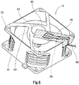
- thermosetting resin 20 in a liquid state is poured into the groove portion 81, in which the lead wires 60 are accommodated, from above (i.e., from the side on which the motor 2 is disposed) as illustrated in FIG. 6 .
- the thermosetting resin 20 is arranged not only in the groove portion 81 but also in at least a portion of the cut portion 82.
- thermosetting resin 20 is arranged to extend from the radially innermost end of the groove portion 81 in the vicinity of the junction of the groove portion 81 with the bottom plate portion 62 to the position radially outward of the projecting portion 681, which is the radially outermost one of the projecting portions 68, in the vicinity of the junction of the groove portion 81 with the tubular portion 61.
- thermosetting resin 20 arranged in the fan motor 1 is cured by heat.
- dozens of fan motors 1 into which the thermosetting resin 20 in the liquid state has been poured are placed in a thermostat oven at a temperature of about 80°C for several hours, so that the thermosetting resin 20 is cured and solidified.
- the thermosetting resin 20 in the liquid state before being cured is sufficiently held without a leakage, because both the groove portion 81 and the cut portion 82 are sufficiently sealed.
- an unwanted external appearance of the fan motor does not occur.
- thermosetting resin 20 arranged in the fan motor 1 After the thermosetting resin 20 arranged in the fan motor 1 is sufficiently cured, the masking tape 30, which has been used for the sealing, is removed from the fan motor 1, so that the thermosetting resin 20 solidified is exposed as illustrated in FIG. 7 .
- thermosetting resin 20 covers a range from the radially innermost end of the groove portion 81 in the vicinity of the junction of the groove portion 81 with the bottom plate portion 62 to the position radially outward of the projecting portion 681, which is the radially outermost one of the projecting portions 68, in the vicinity of the junction of the groove portion 81 with the tubular portion 61.
- the lead wires 60 are securely fixed to the fan motor 1 through the solidified thermosetting resin 20.
- the opening portion 64 is closed with the solidified thermosetting resin 20. This contributes to preventing intrusion of water toward the circuit board 65.
- the thermosetting resin 20 is arranged not only in the groove portion 81 but also in a portion of the cut portion 82.
- the circuit board 65 which is arranged in the lower portion of the motor 2, and a junction of the circuit board 65 with each lead wire 60 are covered with the thermosetting resin 20 to prevent intrusion of water, the fan motor 1 will be waterproof. Accordingly, if the thermosetting resin 20 is poured into the groove portion 81 at the vicinity of the junction of the groove portion 81 with the bottom plate portion 62, and the thermosetting resin 20 is allowed to reach the position of a relatively inward one of the projecting portions 68, required waterproof performance of the fan motor 1 can be achieved. Therefore, the thermosetting resin 20 may not necessarily be arranged to extend up to the cut portion 82.
- the groove portion 81 is defined in only one of the four support portions 63.
- the groove portion 81 may be defined in each of two or more of the support portions 63, and the lead wires 60 may be arranged to extend in a plurality of directions to be drawn out of the fan motor 1.
- Preferred embodiments of the present invention are applicable to fan motors.
Landscapes
- Engineering & Computer Science (AREA)
- Mechanical Engineering (AREA)
- General Engineering & Computer Science (AREA)
- Structures Of Non-Positive Displacement Pumps (AREA)
- Motor Or Generator Frames (AREA)
Abstract
Description
- The present invention relates to a fan motor.
- Axial fan motors arranged to produce axial air flows by rotating impellers using driving forces of motors have been known. The axial fan motors are, for example, installed in household electrical appliances, office automation appliances, transportation equipment, and so on, and are used for the purposes of cooling electronic components, circulating gases in device cases, and so on. In addition, such fan motors are sometimes used for circulating gases in server rooms in which a large number of electronic devices are installed. A known fan motor is described in, for example,
JP-A H11-089155 - The fan motor described in
JP-A H11-089155 - As described above, for the purpose of improving waterproof performance of a fan motor, a process of pouring a thermosetting resin on an area through which a lead wire is drawn out or into a space surrounding the lead wire and curing the thermosetting resin is often performed. However, during this process, a leakage of the thermosetting resin may sometimes occur. If a leakage of the thermosetting resin occurs, a device to which the fan motor is attached may be affected, and therefore, the thermosetting resin must be removed and the process must be performed again. Moreover, a leakage of the thermosetting resin might result in an unwanted external appearance of the fan motor. There is accordingly a demand for a technique to prevent a leakage of the thermosetting resin and an unwanted external appearance of the fan motor.
- Accordingly, in a process prior to the pouring of the thermosetting resin, an adhesive tape (for example, a masking tape) is often stuck to a rib or an outer frame of the fan motor, for example, to prevent a leakage of the thermosetting resin. However, it may be structurally difficult to properly seal an area through which a lead wire is drawn out on the rib or the outer frame of the fan motor with a masking tape.
- A fan motor according to a preferred embodiment of the present invention includes a motor including a stationary portion and a rotating portion arranged to rotate about a rotation axis extending in a vertical direction; an impeller including a plurality of blades, and arranged to rotate together with the rotating portion; a housing arranged to house the motor and the impeller therein; and a lead wire electrically connected to the motor, and arranged to extend outwardly of the housing. The housing includes a tubular portion being tubular, and arranged to extend from an inlet side to an outlet side along the rotation axis, and house at least a portion of the impeller therein; a bottom plate portion fixed below the motor and radially inside of the tubular portion; and a support portion arranged to extend from at least a portion of the tubular portion toward the bottom plate portion, and joined to at least a portion of the bottom plate portion. The support portion includes a groove portion recessed upward. The tubular portion includes a cut portion defined at a portion thereof continuous with the groove portion. The lead wire is drawn out of the housing through the groove portion and the cut portion. At least one of the groove portion and the cut portion has a thermosetting resin arranged therein.
- In the fan motor according to the above preferred embodiment of the present invention, an area in which the thermosetting resin is arranged can be easily sealed. This contributes to preventing a leakage of the thermosetting resin and an unwanted external appearance of the fan motor.
- The above and other elements, features, steps, characteristics and advantages of the present invention will become more apparent from the following detailed description of the preferred embodiments with reference to the attached drawings.
-
-
FIG. 1 is a vertical sectional view of a fan motor according to a preferred embodiment of the present invention. -
FIG. 2 is a perspective view of a housing according to a preferred embodiment of the present invention. -
FIG. 3 is a bottom view of the housing according to a preferred embodiment of the present invention. -
FIG. 4 is a vertical sectional view of a support portion according to a preferred embodiment of the present invention. -
FIG. 5 is a perspective view of the housing according to a preferred embodiment of the present invention. -
FIG. 6 is a perspective view of the housing according to a preferred embodiment of the present invention. -
FIG. 7 is a perspective view of the housing according to a preferred embodiment of the present invention. - Hereinafter, preferred embodiments of the present invention will be described with reference to the accompanying drawings. It is assumed herein that a direction parallel to a rotation axis of a fan motor is referred to by the term "axial direction", "axial", or "axially", that directions perpendicular to the rotation axis of the fan motor are each referred to by the term "radial direction", "radial", or "radially", and that a direction along a circular arc centered on the rotation axis of the fan motor is referred to by the term "circumferential direction", "circumferential", or "circumferentially".
- It is also assumed herein that, with respect to an axial direction, a side from which air is taken in (i.e., an upper side in
FIG. 1 ) will be referred to as an "inlet side" or simply as an "upper side", and a side toward which the air is discharged (i.e., a lower side inFIG. 1 ) will be referred to as an "outlet side" or simply as a "lower side". Note that the above definitions of the "upper side" and the "lower side" are made simply for the sake of convenience in description, and have no relation to the direction of gravity. Fan motors according to preferred embodiments of the present invention may be used in any orientation. -
FIG. 1 is a vertical sectional view of afan motor 1 according to a preferred embodiment of the present invention. - The
fan motor 1 is used, for example, as an apparatus that supplies a cooling air flow to a household electrical appliance, such as a refrigerator, or an interior of a room, such as a server room, in which a plurality of electronic devices are installed. Thefan motor 1 may be used singly, or alternatively, a plurality offan motors 1 may be used at the same time in combination. For example, a plurality offan motors 1 may be installed in a single server room, and thesefan motors 1 may be driven at the same time. - Referring to
FIG. 1 , thefan motor 1 includes a motor 2, an impeller 3, and ahousing 4. Thefan motor 1 is an axial fan arranged to produce a downward air flow along a rotation axis 9. Once thefan motor 1 is driven, air is taken in from the upper side of thefan motor 1, i.e., from the inlet side, and the air is sent to the lower side of thefan motor 1, i.e., to the outlet side, through awind channel 10. - The motor 2 includes a stationary portion 21 and a rotating
portion 22. The rotatingportion 22 is supported to be rotatable with respect to the stationary portion 21. In addition, the rotatingportion 22 is arranged to rotate about the rotation axis 9, which extends in a vertical direction. - The stationary portion 21 includes a base portion 211, a stator 212, and a bearing member 213. The base portion 211 is arranged to extend along the rotation axis 9 to assume a cylindrical shape. The stator 212 is an armature fixed to an outer circumferential surface of the base portion 211. The stator 212 includes a
stator core 51 and a plurality ofcoils 52. Thestator core 51 includes a plurality of teeth arranged to extend radially. Each of thecoils 52 is defined by a conducting wire wound around a separate one of the teeth. - The bearing member 213 is a cylindrical member arranged radially inside of the base portion 211. The bearing member 213 is fixed to an inner circumferential surface of the base portion 211 through, for example, an adhesive. A lower portion of a
shaft 221, which will be described below, is inserted radially inside of the bearing member 213. A lubricating oil is arranged between an inner circumferential surface of the bearing member 213 and an outer circumferential surface of theshaft 221. Theshaft 221 is thus supported to be rotatable with respect to the stationary portion 21. Note, however, that the motor 2 may alternatively include a bearing mechanism of another type, such as, for example, a ball bearing, in place of the bearing member 213. - The rotating
portion 22 includes theshaft 221, arotor holder 222, and amagnet 223. Theshaft 221 is a columnar member arranged to extend along the rotation axis 9. Theshaft 221 is rotatably supported by the base portion 211 through the bearing member 213. An upper end portion of theshaft 221 is arranged to project upward above the bearing member 213. While the motor 2 is running, theshaft 221 rotates about the rotation axis 9. - The
rotor holder 222 is a member in the shape of a covered cylinder, including a disk-shapedrotor cover portion 53 arranged to extend substantially perpendicularly to the rotation axis 9, and arotor tubular portion 54 arranged to extend from therotor cover portion 53 to the outlet side. A metal or a resin, for example, is used as a material of therotor holder 222. A central portion of therotor cover portion 53 is fixed to the upper end portion of theshaft 221. Therotor holder 222 is thus arranged to rotate together with theshaft 221. Therotor cover portion 53 is arranged on the inlet side of the stationary portion 21. Therotor tubular portion 54 is arranged radially outside of the stator 212. - The impeller 3 includes a plurality of blades. An inner end portion of each blade is joined to the
rotor tubular portion 54. That is, each blade is arranged to extend radially outward from a junction of the blade with therotor tubular portion 54. The impeller 3 is arranged to rotate together with theshaft 221 and therotor holder 222 of the rotatingportion 22. The blades are arranged at substantially regular intervals in a circumferential direction. Note that the number of blades is not limited to particular values. - The
housing 4 is a case arranged to house the motor 2 and the impeller 3 therein.FIG. 2 is a perspective view of thehousing 4 as viewed obliquely from below.FIG. 3 is a bottom view of thehousing 4. Referring toFIGS. 1 to 3 , thehousing 4 includes atubular portion 61, abottom plate portion 62, and a plurality of support portions (ribs) 63. - The
tubular portion 61 is tubular and is arranged to extend from the inlet side (i.e., the upper side) to the outlet side (i.e., the lower side) along the rotation axis 9. Thetubular portion 61 is arranged to extend radially outside of the impeller 3 to substantially assume a cylindrical shape. Thetubular portion 61 is arranged to house at least a portion of the impeller 3 therein. That is, thetubular portion 61 is arranged in an annular shape radially outside of the impeller 3 to surround the impeller 3. - The
housing 4 includes thebottom plate portion 62, which is fixed below the motor 2 and radially inside of thetubular portion 61. Thebottom plate portion 62 is arranged radially inside of thetubular portion 61 and below the stator 212. Referring toFIGS. 1 and2 , thebottom plate portion 62 includes a disk-shapedportion 621 and acircumferential wall portion 622. The disk-shapedportion 621 is arranged to extend substantially perpendicularly to the rotation axis 9. Thecircumferential wall portion 622 is arranged to extend upward from an outer circumferential portion of the disk-shapedportion 621 to assume a tubular shape. A lower end portion of the base portion 211 of the motor 2 is fixed to the disk-shapedportion 621. In the present preferred embodiment, the base portion 211 and thebottom plate portion 62 are defined by a single continuous monolithic member. Note, however, that the base portion 211 and thebottom plate portion 62 may alternatively be defined by separate members. - Referring to
FIG. 2 , thehousing 4 includes the plurality ofsupport portions 63. Eachsupport portion 63 is arranged to extend from at least a portion of an inner surface of thetubular portion 61 toward thebottom plate portion 62, and is joined to at least a portion of thebottom plate portion 62. The stationary portion 21 of the motor 2 is thus positioned with respect to thehousing 4. In the present preferred embodiment, the number ofsupport portions 63 is four. Note, however, that the number ofsupport portions 63 may alternatively be one, two, three, or more than four. - The
support portions 63 are arranged at regular intervals in the circumferential direction around thebottom plate portion 62. Eachsupport portion 63 is arranged to extend in a straight line perpendicularly to the axial direction. Referring toFIG. 2 , eachsupport portion 63 according to the present preferred embodiment is arranged to extend along a tangent to a circular outer circumference of thebottom plate portion 62. Note, however, that eachsupport portion 63 may not necessarily be arranged to extend along the tangent to the outer circumference of thebottom plate portion 62. Eachsupport portion 63 may alternatively be arranged to extend in a radial direction. - As indicated by broken lines in
FIGS. 2 and3 , it is assumed that eachsupport portion 63 extends from the circular outer circumference of thebottom plate portion 62 to an inner circumference of thetubular portion 61 in the present preferred embodiment. Thebottom plate portion 62 and eachsupport portion 63 are smoothly joined to each other, and are defined integrally with each other. Further, eachsupport portion 63 and thetubular portion 61 are smoothly joined to each other, and are defined integrally with each other. Specifically, thetubular portion 61, thebottom plate portion 62, and thesupport portions 63 are defined in one piece by a resin injection molding process. Note, however, that any two or more of thetubular portion 61, thebottom plate portion 62, and thesupport portions 63 may alternatively be defined by separate members. - At both an upper end and a lower end of the
tubular portion 61, thehousing 4 includes a plurality offlange portions 73 each of which is arranged to project radially outward. In the present preferred embodiment, at each of the upper and lower ends of thetubular portion 61, four of theflange portions 73 are arranged at regular intervals in the circumferential direction. When thefan motor 1 is used, theflange portions 73 are fixed to a frame of a household electrical appliance or the like through screws. Note, however, that theflange portions 73 may not necessarily be provided in thehousing 4. Also note that theflange portions 73 may alternatively be provided at only one of the upper and lower ends of thetubular portion 61. - Next, the structure of a portion of the
fan motor 1 at which athermosetting resin 20 is arranged will now be described below. Leadwires 60 are shown inFIG. 2 . - Referring to
FIG. 2 , at least one of the foursupport portions 63 is wider than theother support portions 63, and includes agroove portion 81 recessed upward (i.e., to the side on which the motor 2 is disposed). Thegroove portion 81 is arranged to extend along a longitudinal direction of thesupport portion 63. In addition, at a lower surface of thetubular portion 61, acut portion 82 is defined at a portion of thetubular portion 61 which is continuous with thegroove portion 81, more specifically, a portion of thetubular portion 61 which is continuous with thegroove portion 81 on a radially outward extension of thesupport portion 63 along the longitudinal direction thereof. - The
cut portion 82 is defined by cutting a portion of thetubular portion 61 substantially in a radial direction. Note that this cutting is done slightly obliquely with respect to the radial direction, in a direction parallel to the longitudinal direction of thesupport portion 63. Further, thetubular portion 61 includes restrictingportions 67 in the vicinity of thecut portion 82. A radially outer surface of each restrictingportion 67 is arranged to have a sufficient area to allow amasking tape 30 to be stuck thereto. The restrictingportions 67 are arranged to extend in the axial direction on both circumferential sides of thecut portion 82. Each restrictingportion 67 is arranged to have an axial dimension greater than that of eachflange portion 73, allowing the maskingtape 30 to be easily stuck thereto. - As described above, at least a portion of a lower surface of each of the
support portions 63 is smoothly and continuously joined to each of at least a portion of the lower surface of thetubular portion 61 and at least a portion of a lower surface of thebottom plate portion 62 in a radial direction. This makes it possible to easily cover at least a portion of the lower surface of eachsupport portion 63, at least a portion of the lower surface of thetubular portion 61, and at least a portion of the lower surface of thebottom plate portion 62 with the maskingtape 30 without a gap. A leakage of thethermosetting resin 20, which will be described below, can thus be prevented. - Further, the
bottom plate portion 62 includes a recessedportion 83 defined in at least a portion of the lower surface thereof. A nameplate or the like is typically installed in the recessedportion 83. The recessedportion 83 prevents a shoulder from being defined due to the thickness of the nameplate when the nameplate is stuck to thebottom plate portion 62. - Furthermore, an
end portion 623 of thebottom plate portion 62 at a junction of thebottom plate portion 62 with thesupport portion 63 including thegroove portion 81 is spaced from the recessedportion 83 so as not to overlap with the recessedportion 83. This spacing facilitates an operation of sticking the maskingtape 30 to thebottom plate portion 62 in preparation for pouring of thethermosetting resin 20. - As illustrated in
FIGS. 2 and3 , an openingportion 64 is defined in the vicinity of the junction of thebottom plate portion 62 with thesupport portion 63. In addition, at least a portion of acircuit board 65, which is arranged in a lower portion of the motor 2, is exposed outwardly through the openingportion 64 on the lower side of thefan motor 1. - Each
lead wire 60 is electrically connected to thecircuit board 65 of the motor 2. Thelead wire 60 is arranged to pass through the openingportion 64 on the axially lower side, be accommodated in thegroove portion 81 of thesupport portion 63, and extend radially outward along thegroove portion 81. Thelead wire 60 is arranged to pass through thegroove portion 81 and thecut portion 82, and is drawn out of thehousing 4, that is, out of thefan motor 1. Thegroove portion 81 is arranged to have sufficient depth and width to allow thelead wires 60 to be accommodated therein. -
FIG. 4 is a sectional view of thesupport portion 63 taken along line X-X inFIG. 3 . As illustrated inFIGS. 3 and4 , thesupport portion 63 includes a plurality of projectingportions 68. Each of the projectingportions 68 is arranged to project in a direction that crosses the longitudinal direction of thesupport portion 63 in thegroove portion 81. Eachlead wire 60 is accommodated in aspace 682 to the side of the projectingportions 68 in thegroove portion 81. That is, the projectingportions 68 are arranged to hold thelead wires 60 accommodated in thegroove portion 81 at a plurality of positions to prevent thelead wires 60 from protruding from a surface of thethermosetting resin 20 and downward out of thegroove portion 81. - Referring to
FIG. 4 , thesupport portion 63 includes atapered surface 631 which is angled with respect to both the axial and circumferential directions. The direction of an air flow passing through thewind channel 10 can thus be adjusted to achieve improved characteristics of thefan motor 1. Moreover, noise caused by rotation of thefan motor 1 can thus be minimized. - As described below, the
thermosetting resin 20 is arranged to extend from a radially innermost end of thegroove portion 81 in the vicinity of a junction of thegroove portion 81 with thebottom plate portion 62 to a position radially outward of a projectingportion 681, which is the radially outermost one of the projectingportions 68, in the vicinity of a junction of thegroove portion 81 with thetubular portion 61. In the present preferred embodiment, the projectingportion 681, which is the radially outermost one of the projectingportions 68, is arranged to have the greatest axial dimension of all the projectingportions 68. Radially outward spreading of thethermosetting resin 20 and an inflow of thethermosetting resin 20 can thus be controlled. - At least portions of the
lead wires 60 which are accommodated in the space to the side of the projectingportions 68 in thegroove portion 81 are preferably coated with a heat-shrinkable tube 69 made of, for example, a polyester resin. In this case, the heat-shrinkable tube 69, which bundles thelead wires 60, is caught by the projectingportions 68. This contributes to preventing thelead wires 60 from rising. Moreover, the heat-shrinkable tube 69 serves as a barrier to more effectively prevent a leakage of thethermosetting resin 20. - Next, with reference to
FIGS. 5 ,6 , and7 , a process of arranging the thermosetting resin will now be described below. Each ofFIGS. 5 to 7 is a perspective view of thehousing 4 as viewed obliquely from below (i.e., from the outlet side of the fan motor 1). After thelead wires 60 are connected to thefan motor 1, the maskingtape 30 is stuck to at least a portion of the lower surface of thebottom plate portion 62, at least a portion of the lower surface of thesupport portion 63, and at least a portion of each restrictingportion 67 without a gap as illustrated inFIG. 5 . A tape made of a resin, for example, is used as the maskingtape 30. Both thegroove portion 81 and thecut portion 82 are sealed with the maskingtape 30. Here, if thecut portion 82 were not sufficiently sealed therewith, thethermosetting resin 20 might travel along thelead wires 60 due to capillary action and leak out beyond thecut portion 82 when thethermosetting resin 20 is poured. In the present preferred embodiment, however, each restrictingportion 67 is arranged to have a sufficient area to allow themasking tape 30 to be stuck thereto. Thecut portion 82 can therefore be sufficiently sealed with the maskingtape 30. - Next, the
thermosetting resin 20 in a liquid state is poured into thegroove portion 81, in which thelead wires 60 are accommodated, from above (i.e., from the side on which the motor 2 is disposed) as illustrated inFIG. 6 . Here, thethermosetting resin 20 is arranged not only in thegroove portion 81 but also in at least a portion of thecut portion 82. That is, thethermosetting resin 20 is arranged to extend from the radially innermost end of thegroove portion 81 in the vicinity of the junction of thegroove portion 81 with thebottom plate portion 62 to the position radially outward of the projectingportion 681, which is the radially outermost one of the projectingportions 68, in the vicinity of the junction of thegroove portion 81 with thetubular portion 61. - The
thermosetting resin 20 arranged in thefan motor 1 is cured by heat. For example, dozens offan motors 1 into which thethermosetting resin 20 in the liquid state has been poured are placed in a thermostat oven at a temperature of about 80°C for several hours, so that thethermosetting resin 20 is cured and solidified. In this operation, thethermosetting resin 20 in the liquid state before being cured is sufficiently held without a leakage, because both thegroove portion 81 and thecut portion 82 are sufficiently sealed. In addition, an unwanted external appearance of the fan motor does not occur. - After the
thermosetting resin 20 arranged in thefan motor 1 is sufficiently cured, the maskingtape 30, which has been used for the sealing, is removed from thefan motor 1, so that thethermosetting resin 20 solidified is exposed as illustrated inFIG. 7 . - In this situation, the
thermosetting resin 20 covers a range from the radially innermost end of thegroove portion 81 in the vicinity of the junction of thegroove portion 81 with thebottom plate portion 62 to the position radially outward of the projectingportion 681, which is the radially outermost one of the projectingportions 68, in the vicinity of the junction of thegroove portion 81 with thetubular portion 61. Thelead wires 60 are securely fixed to thefan motor 1 through the solidifiedthermosetting resin 20. In addition, the openingportion 64 is closed with the solidifiedthermosetting resin 20. This contributes to preventing intrusion of water toward thecircuit board 65. - While preferred embodiments of the present invention have been described above, the present invention is not limited to the above-described preferred embodiments.
- First, in the above-described preferred embodiment, the
thermosetting resin 20 is arranged not only in thegroove portion 81 but also in a portion of thecut portion 82. However, if at least thecircuit board 65, which is arranged in the lower portion of the motor 2, and a junction of thecircuit board 65 with eachlead wire 60 are covered with thethermosetting resin 20 to prevent intrusion of water, thefan motor 1 will be waterproof. Accordingly, if thethermosetting resin 20 is poured into thegroove portion 81 at the vicinity of the junction of thegroove portion 81 with thebottom plate portion 62, and thethermosetting resin 20 is allowed to reach the position of a relatively inward one of the projectingportions 68, required waterproof performance of thefan motor 1 can be achieved. Therefore, thethermosetting resin 20 may not necessarily be arranged to extend up to thecut portion 82. - Also, in the above-described preferred embodiment, the
groove portion 81 is defined in only one of the foursupport portions 63. However, depending on the structure of thefan motor 1 or the structure of a device to which thefan motor 1 is attached, thegroove portion 81 may be defined in each of two or more of thesupport portions 63, and thelead wires 60 may be arranged to extend in a plurality of directions to be drawn out of thefan motor 1. In this case, it is desirable that the size and depth of each of thegroove portions 81 and thecut portions 82 be adjusted in accordance with the number oflead wires 60 and the width of eachlead wire 60. - Note that details of the shape of a fan motor according to a preferred embodiment of the present invention may differ from details of the shape of the fan motor as illustrated in the accompanying drawings of the present application. Also note that features of the above-described preferred embodiments and the modifications thereof may be combined appropriately as long as no conflict arises.
- Preferred embodiments of the present invention are applicable to fan motors.
- Features of the above-described preferred embodiments and the modifications thereof may be combined appropriately as long as no conflict arises.
- While preferred embodiments of the present invention have been described above, it is to be understood that variations and modifications will be apparent to those skilled in the art without departing from the scope and spirit of the present invention. The scope of the present invention, therefore, is to be determined solely by the following claims.
Claims (11)
- A fan motor comprising:a motor including a stationary portion and a rotating portion arranged to rotate about a rotation axis extending in a vertical direction;an impeller including a plurality of blades, and arranged to rotate together with the rotating portion;a housing arranged to house the motor and the impeller therein; anda lead wire electrically connected to the motor, and arranged to extend outwardly of the housing; whereinthe housing includes:a tubular portion being tubular, and arranged to extend from an inlet side to an outlet side along the rotation axis, and house at least a portion of the impeller therein;a bottom plate portion fixed below the motor and radially inside of the tubular portion; anda support portion arranged to extend from at least a portion of the tubular portion toward the bottom plate portion, and joined to at least a portion of the bottom plate portion;the support portion includes a groove portion recessed upward;the tubular portion includes a cut portion defined at a portion thereof continuous with the groove portion;the lead wire is drawn out of the housing through the groove portion and the cut portion; andat least one of the groove portion and the cut portion has a thermosetting resin arranged therein.
- The fan motor according to claim 1, wherein the thermosetting resin is arranged at least in the cut portion.
- The fan motor according to claim 1 to 2, wherein the thermosetting resin is arranged at least in the groove portion.
- The fan motor according to claim 3, wherein the support portion further includes a plurality of projecting portions each of which is arranged to project in a direction that crosses a longitudinal direction of the support portion in the groove portion; and
at least a portion of the lead wire is accommodated in a space to a side of the projecting portions in the groove portion. - The fan motor according to claim 4, wherein the thermosetting resin is arranged to extend from a radially innermost end of the groove portion to a position radially outward of the radially outermost one of the projecting portions.
- The fan motor according to claim 1 to5, wherein the support portion includes a tapered surface angled with respect to both axial and circumferential directions.
- The fan motor according to claim 1 to 6, wherein
the bottom plate portion includes a recessed portion defined in at least a portion of a lower surface thereof; and
the recessed portion is spaced from an end portion of the bottom plate portion at a junction of the bottom plate portion with the support portion. - The fan motor according to claim 7, wherein at least a portion of the lower surface of the bottom plate portion is smoothly and continuously joined to at least a portion of a lower surface of the support portion.
- The fan motor according to claim 1 to 8, wherein
the housing includes a flange portion arranged to project radially outward from a lower end of the tubular portion, and restricting portions arranged to extend in an axial direction on both circumferential sides of the cut portion; and
each restricting portion is arranged to have an axial dimension greater than an axial dimension of the flange portion. - The fan motor according to claim 1 to 9, wherein at least a portion of the lead wire is coated with a heat-shrinkable tube.
- The fan motor according to claim 4 to 5, wherein the radially outermost one of the projecting portions is arranged to have a greatest axial dimension of all the projecting portions.
Applications Claiming Priority (1)
| Application Number | Priority Date | Filing Date | Title |
|---|---|---|---|
| JP2016067583A JP2017184433A (en) | 2016-03-30 | 2016-03-30 | Fan motor |
Publications (1)
| Publication Number | Publication Date |
|---|---|
| EP3225853A1 true EP3225853A1 (en) | 2017-10-04 |
Family
ID=58266501
Family Applications (1)
| Application Number | Title | Priority Date | Filing Date |
|---|---|---|---|
| EP17160338.4A Withdrawn EP3225853A1 (en) | 2016-03-30 | 2017-03-10 | Fan motor |
Country Status (4)
| Country | Link |
|---|---|
| US (1) | US10436205B2 (en) |
| EP (1) | EP3225853A1 (en) |
| JP (1) | JP2017184433A (en) |
| CN (1) | CN206555155U (en) |
Families Citing this family (8)
| Publication number | Priority date | Publication date | Assignee | Title |
|---|---|---|---|---|
| US11761449B2 (en) * | 2014-11-14 | 2023-09-19 | Delta Electronics, Inc. | Fan module |
| US20180023578A1 (en) * | 2016-07-21 | 2018-01-25 | Denso International America, Inc. | Fan shroud, fan device, and manufacturing process |
| CN115995908A (en) * | 2021-10-19 | 2023-04-21 | 日本电产株式会社 | Motor and Axial Fan |
| TWI785947B (en) * | 2021-12-27 | 2022-12-01 | 元山科技工業股份有限公司 | Shock absorbing fan housing |
| US12463490B2 (en) * | 2022-01-31 | 2025-11-04 | Nidec Corporation | Motor module |
| JP7744257B2 (en) * | 2022-01-31 | 2025-09-25 | ニデック株式会社 | Motor Module |
| JP7765979B2 (en) * | 2022-01-31 | 2025-11-07 | ニデック株式会社 | blower |
| TWI834296B (en) * | 2022-09-16 | 2024-03-01 | 大陸商深圳興奇宏科技有限公司 | Fan frame electrical connection structur |
Citations (7)
| Publication number | Priority date | Publication date | Assignee | Title |
|---|---|---|---|---|
| US4636669A (en) * | 1984-10-29 | 1987-01-13 | Msl Industries, Inc. | Termination assembly for electric fans |
| JPH05231385A (en) * | 1992-02-25 | 1993-09-07 | Mitsubishi Electric Corp | Blower |
| JPH1189155A (en) | 1997-09-11 | 1999-03-30 | Matsushita Electric Ind Co Ltd | Axial fan motor |
| JP2000116098A (en) * | 1998-10-09 | 2000-04-21 | Sanyo Denki Co Ltd | Brushless fan motor and method of manufacturing the same |
| US20070041857A1 (en) * | 2005-08-19 | 2007-02-22 | Armin Fleig | Fan housing with strain relief |
| JP4223588B2 (en) * | 1998-05-19 | 2009-02-12 | 日本電産サーボ株式会社 | Venturi case of axial fan |
| US20090068009A1 (en) * | 2007-09-07 | 2009-03-12 | Fu Zhun Precision Industry (Shen Zhen) Co., Ltd. | Fan frame |
Family Cites Families (11)
| Publication number | Priority date | Publication date | Assignee | Title |
|---|---|---|---|---|
| US5407324A (en) * | 1993-12-30 | 1995-04-18 | Compaq Computer Corporation | Side-vented axial fan and associated fabrication methods |
| JP3465104B2 (en) | 1998-08-18 | 2003-11-10 | ミネベア株式会社 | Axial blower |
| JP2000209832A (en) * | 1999-01-12 | 2000-07-28 | Minebea Co Ltd | Axial flow fan motor |
| JP3730461B2 (en) * | 1999-10-28 | 2006-01-05 | 山洋電気株式会社 | Waterproof brushless fan motor |
| US6561762B1 (en) * | 2001-11-14 | 2003-05-13 | Sunonwealth Electric Machine Industry Co., Ltd. | Housing structure of a fan |
| US7066720B2 (en) | 2003-06-11 | 2006-06-27 | Asia Vital Components Co., Ltd. | Fan housing |
| JP2005256749A (en) * | 2004-03-12 | 2005-09-22 | Nippon Densan Corp | Fan |
| TWI265666B (en) * | 2005-12-02 | 2006-11-01 | Delta Electronics Inc | Stator structure and manufacturing method thereof |
| US8206104B2 (en) | 2007-12-04 | 2012-06-26 | Sunonwealth Electric Machine Industry Co., Ltd. | Frame structure for fan |
| JP5129667B2 (en) | 2008-06-26 | 2013-01-30 | 山洋電気株式会社 | Axial blower |
| US8033799B2 (en) | 2008-07-09 | 2011-10-11 | Nidec Corporation | Cooling fan unit and method for drawing out lead wires thereof |
-
2016
- 2016-03-30 JP JP2016067583A patent/JP2017184433A/en active Pending
-
2017
- 2017-03-02 CN CN201720199834.9U patent/CN206555155U/en not_active Expired - Fee Related
- 2017-03-10 EP EP17160338.4A patent/EP3225853A1/en not_active Withdrawn
- 2017-03-17 US US15/461,549 patent/US10436205B2/en active Active
Patent Citations (7)
| Publication number | Priority date | Publication date | Assignee | Title |
|---|---|---|---|---|
| US4636669A (en) * | 1984-10-29 | 1987-01-13 | Msl Industries, Inc. | Termination assembly for electric fans |
| JPH05231385A (en) * | 1992-02-25 | 1993-09-07 | Mitsubishi Electric Corp | Blower |
| JPH1189155A (en) | 1997-09-11 | 1999-03-30 | Matsushita Electric Ind Co Ltd | Axial fan motor |
| JP4223588B2 (en) * | 1998-05-19 | 2009-02-12 | 日本電産サーボ株式会社 | Venturi case of axial fan |
| JP2000116098A (en) * | 1998-10-09 | 2000-04-21 | Sanyo Denki Co Ltd | Brushless fan motor and method of manufacturing the same |
| US20070041857A1 (en) * | 2005-08-19 | 2007-02-22 | Armin Fleig | Fan housing with strain relief |
| US20090068009A1 (en) * | 2007-09-07 | 2009-03-12 | Fu Zhun Precision Industry (Shen Zhen) Co., Ltd. | Fan frame |
Also Published As
| Publication number | Publication date |
|---|---|
| JP2017184433A (en) | 2017-10-05 |
| US20170284403A1 (en) | 2017-10-05 |
| CN206555155U (en) | 2017-10-13 |
| US10436205B2 (en) | 2019-10-08 |
Similar Documents
| Publication | Publication Date | Title |
|---|---|---|
| US10436205B2 (en) | Fan motor | |
| EP3496240B1 (en) | Motor and axial flow fan | |
| US9800118B2 (en) | Self-cooled motor | |
| US9800117B2 (en) | Self-cooled motor | |
| JP6728948B2 (en) | Fan motor | |
| US11682933B2 (en) | Motor and fan motor | |
| US20130177461A1 (en) | Axial flow fan | |
| US10666114B2 (en) | Motor | |
| US4904891A (en) | Ventilated electric motor assembly | |
| KR101714477B1 (en) | OUTER ROTOR MOTOR WITH A STREAMLINED Blade for POWER OF of Unmanned Aircraft Robot | |
| CN103532299A (en) | Centrifugal fan | |
| JP2017184525A (en) | Stator unit, motor and parallel fan | |
| US11905960B2 (en) | Fan motor | |
| US10224777B2 (en) | Brushless motor with water stopping walls creating labyrinth structure | |
| JP2008306917A (en) | Electric motor | |
| EP3456978B1 (en) | Blower device | |
| BR102015030823A2 (en) | synchronous motor, rotor, pump and cleaning apparatus | |
| KR20160104427A (en) | Motor with a cooling means | |
| JP2020122397A (en) | Pump device | |
| JP6911521B2 (en) | Motor and fan motor | |
| CN110224518A (en) | A kind of fan motor and centrifugal blower | |
| JP2018093584A (en) | Parallel fan | |
| JP5931809B2 (en) | Rotating electrical machine | |
| WO2016103396A1 (en) | Motor, air conditioning device, and motor manufacturing method |
Legal Events
| Date | Code | Title | Description |
|---|---|---|---|
| PUAI | Public reference made under article 153(3) epc to a published international application that has entered the european phase |
Free format text: ORIGINAL CODE: 0009012 |
|
| AK | Designated contracting states |
Kind code of ref document: A1 Designated state(s): AL AT BE BG CH CY CZ DE DK EE ES FI FR GB GR HR HU IE IS IT LI LT LU LV MC MK MT NL NO PL PT RO RS SE SI SK SM TR |
|
| AX | Request for extension of the european patent |
Extension state: BA ME |
|
| 17P | Request for examination filed |
Effective date: 20180404 |
|
| RBV | Designated contracting states (corrected) |
Designated state(s): AL AT BE BG CH CY CZ DE DK EE ES FI FR GB GR HR HU IE IS IT LI LT LU LV MC MK MT NL NO PL PT RO RS SE SI SK SM TR |
|
| GRAP | Despatch of communication of intention to grant a patent |
Free format text: ORIGINAL CODE: EPIDOSNIGR1 |
|
| STAA | Information on the status of an ep patent application or granted ep patent |
Free format text: STATUS: GRANT OF PATENT IS INTENDED |
|
| INTG | Intention to grant announced |
Effective date: 20200708 |
|
| STAA | Information on the status of an ep patent application or granted ep patent |
Free format text: STATUS: THE APPLICATION IS DEEMED TO BE WITHDRAWN |
|
| 18D | Application deemed to be withdrawn |
Effective date: 20201119 |