EP3225818B1 - Conceptions de moteur de turbine pour une meilleure efficacité de séparation de fines particules - Google Patents
Conceptions de moteur de turbine pour une meilleure efficacité de séparation de fines particules Download PDFInfo
- Publication number
- EP3225818B1 EP3225818B1 EP17157027.8A EP17157027A EP3225818B1 EP 3225818 B1 EP3225818 B1 EP 3225818B1 EP 17157027 A EP17157027 A EP 17157027A EP 3225818 B1 EP3225818 B1 EP 3225818B1
- Authority
- EP
- European Patent Office
- Prior art keywords
- turbine engine
- annular wall
- flow path
- outer annular
- arc
- Prior art date
- Legal status (The legal status is an assumption and is not a legal conclusion. Google has not performed a legal analysis and makes no representation as to the accuracy of the status listed.)
- Active
Links
- 239000010419 fine particle Substances 0.000 title claims description 41
- 238000000926 separation method Methods 0.000 title claims description 34
- 239000002245 particle Substances 0.000 claims description 43
- 238000000605 extraction Methods 0.000 claims description 23
- 230000007423 decrease Effects 0.000 claims description 6
- 230000003068 static effect Effects 0.000 claims description 5
- 239000003570 air Substances 0.000 description 70
- 239000007789 gas Substances 0.000 description 12
- 238000002485 combustion reaction Methods 0.000 description 11
- 239000000446 fuel Substances 0.000 description 7
- 238000011144 upstream manufacturing Methods 0.000 description 5
- 238000009825 accumulation Methods 0.000 description 4
- 239000012530 fluid Substances 0.000 description 4
- 239000004576 sand Substances 0.000 description 4
- 239000012080 ambient air Substances 0.000 description 2
- 238000005516 engineering process Methods 0.000 description 2
- 230000002093 peripheral effect Effects 0.000 description 2
- 238000005452 bending Methods 0.000 description 1
- 230000015556 catabolic process Effects 0.000 description 1
- 239000000567 combustion gas Substances 0.000 description 1
- 230000006835 compression Effects 0.000 description 1
- 238000007906 compression Methods 0.000 description 1
- 238000006731 degradation reaction Methods 0.000 description 1
- 230000002939 deleterious effect Effects 0.000 description 1
- 239000000428 dust Substances 0.000 description 1
- 239000011521 glass Substances 0.000 description 1
- 238000002347 injection Methods 0.000 description 1
- 239000007924 injection Substances 0.000 description 1
- 238000012423 maintenance Methods 0.000 description 1
- 230000007246 mechanism Effects 0.000 description 1
- 239000000203 mixture Substances 0.000 description 1
- 230000002028 premature Effects 0.000 description 1
- 230000007704 transition Effects 0.000 description 1
Images


Classifications
-
- F—MECHANICAL ENGINEERING; LIGHTING; HEATING; WEAPONS; BLASTING
- F02—COMBUSTION ENGINES; HOT-GAS OR COMBUSTION-PRODUCT ENGINE PLANTS
- F02C—GAS-TURBINE PLANTS; AIR INTAKES FOR JET-PROPULSION PLANTS; CONTROLLING FUEL SUPPLY IN AIR-BREATHING JET-PROPULSION PLANTS
- F02C7/00—Features, components parts, details or accessories, not provided for in, or of interest apart form groups F02C1/00 - F02C6/00; Air intakes for jet-propulsion plants
-
- F—MECHANICAL ENGINEERING; LIGHTING; HEATING; WEAPONS; BLASTING
- F01—MACHINES OR ENGINES IN GENERAL; ENGINE PLANTS IN GENERAL; STEAM ENGINES
- F01D—NON-POSITIVE DISPLACEMENT MACHINES OR ENGINES, e.g. STEAM TURBINES
- F01D25/00—Component parts, details, or accessories, not provided for in, or of interest apart from, other groups
- F01D25/30—Exhaust heads, chambers, or the like
-
- F—MECHANICAL ENGINEERING; LIGHTING; HEATING; WEAPONS; BLASTING
- F01—MACHINES OR ENGINES IN GENERAL; ENGINE PLANTS IN GENERAL; STEAM ENGINES
- F01D—NON-POSITIVE DISPLACEMENT MACHINES OR ENGINES, e.g. STEAM TURBINES
- F01D25/00—Component parts, details, or accessories, not provided for in, or of interest apart from, other groups
- F01D25/32—Collecting of condensation water; Drainage ; Removing solid particles
-
- F—MECHANICAL ENGINEERING; LIGHTING; HEATING; WEAPONS; BLASTING
- F01—MACHINES OR ENGINES IN GENERAL; ENGINE PLANTS IN GENERAL; STEAM ENGINES
- F01D—NON-POSITIVE DISPLACEMENT MACHINES OR ENGINES, e.g. STEAM TURBINES
- F01D9/00—Stators
- F01D9/02—Nozzles; Nozzle boxes; Stator blades; Guide conduits, e.g. individual nozzles
-
- F—MECHANICAL ENGINEERING; LIGHTING; HEATING; WEAPONS; BLASTING
- F02—COMBUSTION ENGINES; HOT-GAS OR COMBUSTION-PRODUCT ENGINE PLANTS
- F02C—GAS-TURBINE PLANTS; AIR INTAKES FOR JET-PROPULSION PLANTS; CONTROLLING FUEL SUPPLY IN AIR-BREATHING JET-PROPULSION PLANTS
- F02C7/00—Features, components parts, details or accessories, not provided for in, or of interest apart form groups F02C1/00 - F02C6/00; Air intakes for jet-propulsion plants
- F02C7/36—Power transmission arrangements between the different shafts of the gas turbine plant, or between the gas-turbine plant and the power user
-
- F—MECHANICAL ENGINEERING; LIGHTING; HEATING; WEAPONS; BLASTING
- F04—POSITIVE - DISPLACEMENT MACHINES FOR LIQUIDS; PUMPS FOR LIQUIDS OR ELASTIC FLUIDS
- F04D—NON-POSITIVE-DISPLACEMENT PUMPS
- F04D29/00—Details, component parts, or accessories
- F04D29/40—Casings; Connections of working fluid
- F04D29/42—Casings; Connections of working fluid for radial or helico-centrifugal pumps
- F04D29/4206—Casings; Connections of working fluid for radial or helico-centrifugal pumps especially adapted for elastic fluid pumps
- F04D29/4213—Casings; Connections of working fluid for radial or helico-centrifugal pumps especially adapted for elastic fluid pumps suction ports
-
- F—MECHANICAL ENGINEERING; LIGHTING; HEATING; WEAPONS; BLASTING
- F04—POSITIVE - DISPLACEMENT MACHINES FOR LIQUIDS; PUMPS FOR LIQUIDS OR ELASTIC FLUIDS
- F04D—NON-POSITIVE-DISPLACEMENT PUMPS
- F04D29/00—Details, component parts, or accessories
- F04D29/70—Suction grids; Strainers; Dust separation; Cleaning
- F04D29/701—Suction grids; Strainers; Dust separation; Cleaning especially adapted for elastic fluid pumps
-
- F—MECHANICAL ENGINEERING; LIGHTING; HEATING; WEAPONS; BLASTING
- F04—POSITIVE - DISPLACEMENT MACHINES FOR LIQUIDS; PUMPS FOR LIQUIDS OR ELASTIC FLUIDS
- F04D—NON-POSITIVE-DISPLACEMENT PUMPS
- F04D29/00—Details, component parts, or accessories
- F04D29/40—Casings; Connections of working fluid
- F04D29/42—Casings; Connections of working fluid for radial or helico-centrifugal pumps
- F04D29/44—Fluid-guiding means, e.g. diffusers
- F04D29/441—Fluid-guiding means, e.g. diffusers especially adapted for elastic fluid pumps
-
- F—MECHANICAL ENGINEERING; LIGHTING; HEATING; WEAPONS; BLASTING
- F05—INDEXING SCHEMES RELATING TO ENGINES OR PUMPS IN VARIOUS SUBCLASSES OF CLASSES F01-F04
- F05D—INDEXING SCHEME FOR ASPECTS RELATING TO NON-POSITIVE-DISPLACEMENT MACHINES OR ENGINES, GAS-TURBINES OR JET-PROPULSION PLANTS
- F05D2220/00—Application
- F05D2220/30—Application in turbines
- F05D2220/32—Application in turbines in gas turbines
-
- F—MECHANICAL ENGINEERING; LIGHTING; HEATING; WEAPONS; BLASTING
- F05—INDEXING SCHEMES RELATING TO ENGINES OR PUMPS IN VARIOUS SUBCLASSES OF CLASSES F01-F04
- F05D—INDEXING SCHEME FOR ASPECTS RELATING TO NON-POSITIVE-DISPLACEMENT MACHINES OR ENGINES, GAS-TURBINES OR JET-PROPULSION PLANTS
- F05D2250/00—Geometry
- F05D2250/50—Inlet or outlet
- F05D2250/52—Outlet
-
- F—MECHANICAL ENGINEERING; LIGHTING; HEATING; WEAPONS; BLASTING
- F05—INDEXING SCHEMES RELATING TO ENGINES OR PUMPS IN VARIOUS SUBCLASSES OF CLASSES F01-F04
- F05D—INDEXING SCHEME FOR ASPECTS RELATING TO NON-POSITIVE-DISPLACEMENT MACHINES OR ENGINES, GAS-TURBINES OR JET-PROPULSION PLANTS
- F05D2260/00—Function
- F05D2260/40—Transmission of power
- F05D2260/403—Transmission of power through the shape of the drive components
- F05D2260/4031—Transmission of power through the shape of the drive components as in toothed gearing
- F05D2260/40311—Transmission of power through the shape of the drive components as in toothed gearing of the epicyclical, planetary or differential type
-
- F—MECHANICAL ENGINEERING; LIGHTING; HEATING; WEAPONS; BLASTING
- F05—INDEXING SCHEMES RELATING TO ENGINES OR PUMPS IN VARIOUS SUBCLASSES OF CLASSES F01-F04
- F05D—INDEXING SCHEME FOR ASPECTS RELATING TO NON-POSITIVE-DISPLACEMENT MACHINES OR ENGINES, GAS-TURBINES OR JET-PROPULSION PLANTS
- F05D2260/00—Function
- F05D2260/60—Fluid transfer
- F05D2260/607—Preventing clogging or obstruction of flow paths by dirt, dust, or foreign particles
-
- Y—GENERAL TAGGING OF NEW TECHNOLOGICAL DEVELOPMENTS; GENERAL TAGGING OF CROSS-SECTIONAL TECHNOLOGIES SPANNING OVER SEVERAL SECTIONS OF THE IPC; TECHNICAL SUBJECTS COVERED BY FORMER USPC CROSS-REFERENCE ART COLLECTIONS [XRACs] AND DIGESTS
- Y02—TECHNOLOGIES OR APPLICATIONS FOR MITIGATION OR ADAPTATION AGAINST CLIMATE CHANGE
- Y02T—CLIMATE CHANGE MITIGATION TECHNOLOGIES RELATED TO TRANSPORTATION
- Y02T50/00—Aeronautics or air transport
- Y02T50/60—Efficient propulsion technologies, e.g. for aircraft
Definitions
- the present disclosure generally relates to turbine engine technologies. More particularly, the present disclosure relates to turbine engine designs for improved fine particle (such as sand) separation efficiency.
- Turbine engines are used for a number of purposes, including propulsion and/or driving various other components with electrical, pneumatic, and/or hydraulic power, and may include both propulsion engines and auxiliary power units (APUs).
- a gas turbine engine includes a compressor section, a combustion section, and a turbine section.
- the compressor section draws in ambient air, compresses the air with one or more compressors, and supplies the compressed air to the combustion section.
- the combustion section receives fuel via a fuel injection assembly, mixes the fuel with the compressed air, ignites the mixture, and supplies the high energy combustion gases to the turbine section to drive one or more turbines, including a shaft that may be used to drive the compressor and other components.
- a conventional inlet particle separator typically includes a duct system having a fluid passageway that transitions into a scavenge flow path and an engine flow path. Air that is induced into the fluid passageway may have particles suspended therein. The inertia of relatively larger ones of the suspended particles tends to cause these particles to travel in a straight line rather than follow the fluid passageway.
- the inlet particle separator Because of the manner in which the inlet particle separator is configured, most of the suspended particles tend to flow into the scavenge flow path rather curve into the engine flow path. As such, relatively clean air is directed into the engine, and contaminated air, which has the particles suspended therein, is directed through the scavenge flow path and is discharged.
- inlet particle separators operate at relatively high efficiencies for relatively large particles (e.g., > 20 microns, or ⁇ 1000 microns).
- the efficiencies can be relatively low, resulting in a significant amount of these relatively small particles being ingested into the engine.
- These relatively small particles can still have some deleterious effects.
- these particles can plug secondary flow lines and/or can melt and form glass on relatively hot engine components, such as the combustor, which can significantly reduce performance and the operating life of the engines.
- the improved propulsion turbine engines and APUs would exhibit improved particle separation efficiency, particularly with regard to fine sand particles.
- These engines may implement novel particle separation means that are provided in addition to or as an alternative to conventional inlet particle separators, and may be located at positions within the engine that are different as compared to conventional inlet particle separators.
- United States Patent Application Publication No. US 20070235373 describes a diffuser particle separator for a gas turbine engine. The particles are removed from the gas flow immediately prior to entering the combustor plenum, through holes in the outer wall of a diffuser.
- Japanese Patent Publication No. 2002242699 describes a collecting port formed on a diametrical outer peripheral portion of the curved passage on the downstream side of a compressor, a second collecting port in a boundary between a top wall and a peripheral wall in an outer cylinder of a combustion chamber, and a third collecting port on a compressor shroud.
- a turbine engine incorporating a fine particle separation means includes a radial compressor that rotates about a longitudinal axis, and which compresses air fed thereto, a radially-oriented diffuser located downstream and radially outward, with respect to the longitudinal axis, from the radial compressor, and which decreases a velocity of and increases a static pressure of the compressed air exiting the radial compressor, and a flow path positioned downstream and radially outward, with respect to the longitudinal axis, from the diffuser, wherein the flow path comprises an outer annular wall and an inner annular wall between which the compressed air flows, and wherein the flow path comprises an arc that redirects the compressed air from flowing in a substantially radial flow direction to a substantially axial flow direction.
- the turbine engine also includes an extraction slot in the outer annular wall that fluidly connects with a scavenge plenum, the scavenge plenum being positioned adjacent to and radially outward, with respect to the longitudinal axis, from the outer annular wall at a position downstream axially along the flow path from the arc, the extraction slot also being positioned downstream axially along the flow path from the arc.
- a turbine engine incorporating a fine particle separation means includes a radial compressor that rotates about a longitudinal axis, and which compresses air fed thereto, a radially-oriented diffuser located downstream and radially outward, with respect to the longitudinal axis, from the radial compressor, and which decreases a velocity of and increases a static pressure of the compressed air exiting the radial compressor, and a flow path positioned downstream and radially outward, with respect to the longitudinal axis, from the diffuser, wherein the flow path comprises an outer annular wall and an inner annular wall between which the compressed air flows, and wherein the flow path comprises an arc that redirects the compressed air from flowing in a substantially radial flow direction to a substantially axial flow direction.
- the turbine engine further includes a plurality of holes along the outer annular wall that fluidly connect with a second scavenge plenum, the plurality of holes being positioned along the arc, the scavenge plenum being positioned adjacent to and radially outward from, with respect to the longitudinal axis, the arc.
- a turbine engine incorporating a fine particle separation means includes a compressor that rotates about a longitudinal axis, and which compresses air fed thereto and a flow path positioned downstream from the compressor, wherein the flow path comprises an outer annular wall and an inner annular wall between which the compressed air flows, and wherein the flow path comprises an arc the redirects the compressed air from flowing in a substantially radial flow direction to a substantially axial flow direction.
- the turbine engine also includes either or both of 1) an extraction slot in the outer annular wall that fluidly connects with a first scavenge plenum, the first scavenge plenum being positioned adjacent to and radially outward, with respect to the longitudinal axis, from the outer annular wall at a position downstream axially along the flow path from the arc, the extraction slot also being positioned downstream axially along the flow path from the arc, and 2) a plurality of holes along the outer annular wall that fluidly connect with a second scavenge plenum, the plurality of holes being positioned along the arc, the second scavenge plenum being positioned adjacent to and radially outward from, with respect to the longitudinal axis, the arc.
- a gas turbine engine may be used to power various types of vehicles and systems.
- a typical gas turbine engine includes a fan section, a compressor section, a combustor section, a turbine section, and an exhaust section.
- the fan section induces air from the surrounding environment into the engine and accelerates the air toward the compressor section.
- the compressor section compresses the pressure of the air to a relatively high level and directs the air to the combustor section.
- a steady stream of fuel is injected into the combustor section, and the injected fuel is ignited to significantly increase the energy of the compressed air.
- the high-energy compressed air then flows into and through the turbine section, causing rotationally mounted turbine blades therein to rotate and generate energy.
- the air exiting the turbine section is exhausted from the engine via the exhaust section, and the energy remaining in the exhaust air, in the case of propulsion turbine engines, aids the thrust generated by the air flowing through a bypass plenum.
- the compressor section is implemented with a centrifugal compressor.
- a centrifugal compressor typically includes at least one impeller that is rotationally mounted to a rotor and surrounded by a shroud. When the impeller rotates, it compresses and imparts tangential velocity to the air received from the fan section and the shroud directs the air radially outward into a diffuser.
- the diffuser decreases the radial and tangential velocity of the air and increases the static pressure of the air and directs the air into a deswirl assembly.
- the deswirl assembly includes an annular housing having a plurality of straight radially extending vanes mounted therein that straighten and reduce the tangential velocity component of the air flow before it enters the combustor section.
- the combustor section in some turbine engines, is implemented with an axial through-flow combustor that includes an annular combustor disposed within a combustor housing that defines a plenum.
- the straightened air enters the plenum and travels axially through the annular combustor where it is mixed with fuel and ignited.
- FIG. 1 An exemplary embodiment of a multi-spool, propulsion-type gas turbine engine 100 is depicted in FIG. 1 .
- the propulsion-type turbine engine is only one type of turbine engine that may employ the particle separation technologies of the present disclosure (others include, for example, APUs), and thus FIG. 1 should be understood as illustrative but not limiting.
- Turbine engine 100 includes an air intake section 102, a compressor section 104, a combustion section 106, a turbine section 108, and an exhaust section 110.
- the intake section 102 includes a fan 112, which is mounted in a fan case 114. The fan 112 draws air into the intake section 102 and accelerates it.
- a fraction of the accelerated air exhausted from the fan 112 is directed through a bypass section 116 disposed between the fan case 114 and an engine cowl 118, and provides a forward thrust.
- the bypass section 116 need not be present.
- the remaining fraction of air exhausted from the fan 112 is directed into the compressor section 104.
- the compressor section 104 includes two compressors: an intermediate pressure compressor 120 and a high pressure compressor 122.
- Compressors may generally be embodied as radial or mixed flow types. In other embodiments, more or fewer than two compressors may be provided.
- the intermediate pressure compressor 120 raises the pressure of the air directed into it from the fan 112, and directs the compressed air into the high pressure compressor 122.
- the high pressure compressor 122 compresses the air still further, and directs the high pressure air into the combustion section 106.
- the combustion section 106 which includes an annular combustor 124, the high pressure air is mixed with fuel and combusted. The combusted air is then directed into the turbine section 108.
- the turbine section 108 includes three turbines disposed in axial flow series, a high pressure turbine 126, an intermediate pressure turbine 128, and a low pressure turbine 130.
- a high pressure turbine 126 expands through each turbine 126, 128, 130, causing each turbine to rotate.
- the air is then exhausted through a propulsion nozzle 132 (in the case of a propulsion turbine engine) disposed in the exhaust section 110, providing additional forward thrust.
- a propulsion nozzle 132 in the case of a propulsion turbine engine
- each drives equipment in the engine 100 via concentrically disposed shafts or spools.
- the high pressure turbine 126 drives the high pressure compressor 122 via a high pressure spool 134
- the intermediate pressure turbine 128 drives the intermediate pressure compressor 120 via an intermediate pressure spool 136
- the low pressure turbine 130 drives the fan 112 via a low pressure spool 138.
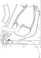
- FIG. 2 an exemplary cross section of the area between the high pressure compressor 122 and annular combustor 124 is illustrated.
- FIG. 2 depicts a radially-oriented diffuser 204 and a deswirl assembly 206, each disposed about a longitudinal axis 207.
- the high pressure compressor 122 is embodied as a centrifugal compressor and includes an impeller 208 and a shroud 210 disposed in a compressor housing 211.
- the impeller 208 as alluded to above, is driven by the high pressure turbine 126 and rotates about the longitudinal axis 207.
- the shroud 210 is disposed around the impeller 208 and defines an impeller discharge flow passage 212 therewith that extends radially outward from longitudinal axis 207. While a radial compressor 122 is disclosed, other types, including mixed flow, may be employed as well.
- the diffuser 204 is coupled to the shroud 210 and is configured to decrease the velocity and increase the static pressure of air that is received from impeller 208.
- any one of numerous conventional diffusers 204 suitable for operating with a centrifugal compressor may be employed.
- the diffuser 204 includes an inlet 214, an outlet 216, and a flow path 218 that each communicates with the impeller discharge flow passage 212, and the flow path 218 is configured to direct the received air flow radially outward.
- the deswirl assembly 206 communicates with the diffuser 204 and is configured to substantially remove swirl from air received therefrom, to thereby decrease the Mach number of the air flow.
- the deswirl assembly 206 includes an inner annular wall 220, an outer annular wall 222, and pluralities of vanes 224, 226 disposed between the inner annular wall 220 and the outer annular wall 222.
- the walls 220, 222 define a flow path 228 that is configured to redirect the air from its radially outward direction to a radially inward and axially downstream direction.
- the walls 220, 222 are formed such that the flow path 228 extends between an inlet 230 and outlet 232 in an arc 233 so that when the air exits the outlet 232, it is directed at an angle toward the longitudinal axis 207 and the annular combustor 124.
- the angle of the arc 233 is increased the variation of the air angle between the inner wall 220 and out wall 222 is increased.
- the turbine engine 100 may be configured with an inlet particle separator, located upstream of the compressor section 104, for purposes of efficiently removing relatively large particles (greater than 5 microns, or greater than 20 microns) from the inlet air stream.
- finer particles such as those smaller than 20 microns, or smaller than 5 microns, may elude the inlet particle separator, and proceed into the turbine engine compressor section 104.
- the present disclosure provides additional features, which may be located in the turbine engine compressor section 104, as an alternative or in addition to an inlet particle separator, that serve to efficiently separate any smaller particles from the air stream in the compressor section 104, and thus prevent such smaller particles from entering into the combustor section 106.
- a first fine particle separation means 300 may be embodied as a scavenge plenum connected to the deswirl assembly flow path 228 by means of an extraction slot through the deswirl assembly outer annular wall 222 downstream of the arc 233.
- a second fine particle separation means 400 may be embodied as scavenge plenum connected to the deswirl assembly flow path 228 by means of a plurality of holes in the deswirl assembly outer annular wall 222 along the length of the arc 233.
- a third fine particle separation means may be embodied as a hybrid combination of fine particle separation means 300 and 400. Each of the first, second, and third separation means is described in greater detail below with regard to FIGS. 3A - B, 4A - B, and 5 , respectively.
- the deswirl assembly flow path 228, which as noted above is formed between the inner and outer deswirl annular walls 220, 222.
- the compressed air once passing through the diffuser 204 (via diffuser flow path 218), enters into the deswirl assembly 206 at the deswirl inlet 230.
- the deswirl assembly 206 changes the flow direction of the compressed air from a radially outward direction from the longitudinal axis 207, to an axially rearward direction (towards the combustor section 106) that also include a small radially inward (downward) component, as illustrated.
- the first fine particle separation means 300 includes an extraction slot 306 in the outer annular wall that leads to a scavenge plenum 305.
- the extraction slot 306 may be embodied as a continuous slot, or as a series of holes of any shape or count.
- the extraction slot is axi-symmetrical, and may encompass from about 1% to about 25%, such as about 1% to about 15%, of the area (along a plane perpendicular to the longitudinal axis 207) of the flow path 228.
- the extraction slot 306 is located along the deswirl flow path 228 at a position downstream of the arc 233, yet prior to the plurality of vanes 224, 226.
- the extraction slot 306 should be sized such that bleed air through the extraction slot 306 amounts to less than 5%, such as less than 1% of total air flow, preferably as close to 0% as possible.
- the scavenge plenum 305 is located radially outward from the deswirl assembly 206 at a position that is radially adjacent to the first (upstream) plurality of vanes 224.
- the scavenge plenum 305 includes an inner radial wall 302, an outer radial wall 301, and an axial end wall 303 positioned at an opposite axial (downstream) end of the plenum 305 with respect to the extraction slot 306.
- a radius of the outer radial wall 301 that connects with the axial end wall 303 is greater than the radius at which the extraction slot 306 is located, and likewise, it is preferred that a radius of the inner radial wall 302 that connects with the axial end wall 303 is at a lower radius than the radius at which the extraction slot 306 is located, all with respect to the longitudinal axis 207.
- the aforesaid small radially inward component of the flow direction is commenced at the plurality of vanes 224, 226 by the vanes 224, 226 being oriented somewhat radially inward (e.g., about 10 to about 45 degrees).
- the inner radial wall 302 of the scavenge plenum 305 may also have the same radial declination so as to remain parallel and adjacent to the first plurality of vanes 224, as noted above.
- the compressed air that exits the diffuser 204 at diffuser outlet 216 will enter the deswirl assembly at inlet 230. Any fine particles in the compressed air, as it passes through the deswirl flow path 228, will tend to track along the arc 233 of outer annular wall 222. Prior to encountering the plurality of vanes 224, 226 (and thus prior to the radial declination at the vanes), the fine particles will be extracted from the flow path 228 at the extraction slot 306 located along the outer annular wall 222, and enter into the scavenge plenum 305.
- any fine particle accumulation in the scavenge plenum 305 may be removed from time to time by an appropriate port along any wall of the scavenge plenum 305.
- the scavenge plenum 305 may also incorporate "smart" particle removal mechanisms, such as an electronically-controlled port(s) connected to an engine exhaust or downstream section of the engine, which can be selectively turned on when needed to actively clean particle accumulation out of the plenum 305 under operating and non-operating conditions.
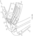
- the deswirl assembly outer annular wall 222 is fitted with a plurality of holes 406 along the arc 233.
- the holes extend through the outer annular wall 222 and the shroud 211 and open into a scavenge plenum 405, the scavenge plenum 405 being positioned radially outward from and adjacent to the deswirl assembly 206 along the arc 233.
- the diameter of the holes may vary from embodiment to embodiment, in a typical embodiment, the holes 406 may have a diameter of about 0.03 inches to about 0.07 inches, such as about 0.05 inches.
- the spacing between the holes 406 in circumferential rows may be equal to or greater than one diameter of the holes, whereas axial spacing between rows may be staggered to allow the maximum number of holes while maintaining the integrity of the outer annular wall 222 and the shroud 211.
- the plurality of holes have a circumferential angle or "lean" that may be from about 25 to about 65 degrees with respect to the outer annular wall 222, such as from about 35 to about 55 degrees.
- the plurality of holes may also have an axial (rearward, toward the combustor section 106) angle or lean that may be from about 5 to about 20 degrees, for example from about 10 to about 15 degrees, again with respect to the outer annular wall 222.
- Bleed air through the plurality of holes 406 amounts to less than 5%, such as less than 1% of total air flow, preferably as close to 0% as possible.
- the scavenge plenum 405 scavenge has a section of higher radius so that the already trapped fine particles would continue to rotate freely in the tangential direction and help negate the need of active scavenge flow bleed.
- the scavenge plenum 405, connected with the plurality of holes 406, may include an inner radial wall 402, and outer radial wall 401, and an axial end wall 403 positioned at an aft-most (downstream) end of the scavenge plenum 405.
- the inner radial wall 402 and out the outer radial wall 401 may be contoured or curved to match the curvature of the arc 233, such that each of the plurality of holes 406 extends about the same distance between the deswirl assembly flow path 228 and the scavenge plenum 405.
- the scavenge plenum 405 scavenge has a section of higher radius so that the already trapped fine particles would continue to rotate freely in the tangential direction and help negate the need of active scavenge flow bleed.
- the compressed air that exits the diffuser 204 at diffuser outlet 216 will enter the deswirl assembly at inlet 230.
- Any fine particles in the compressed air, as it passes through the deswirl flow path 228, will tend to track along the arc 233 of outer annular wall 222.
- the fine particles will be extracted from the flow path 228 through the plurality of holes 406, and enter into the scavenge plenum 405.
- the fine particles are efficiently prevented from entering the combustion section 124, which is positioned axially downstream from the second plurality of vanes 226 and deswirl assembly outlet 232.
- Any fine particle accumulation in the scavenge plenum 405 may be removed from time to time by an appropriate port along any wall of the scavenge plenum 405, for example the "smart" system as described above.
- an extraction slot 306 is provided in the outer annular wall that leads to a scavenge plenum 305.
- the extraction slot 306 is located along the deswirl flow path 228 at a position downstream of the arc 233, yet prior to the plurality of vanes 224, 226.
- the scavenge plenum 305 is located radially outward from the deswirl assembly 206 at a position that is radially adjacent to the first (upstream) plurality of vanes 224.
- the deswirl assembly outer annular wall 222 is fitted with a plurality of holes 406 along the arc 233.
- the holes extend through the outer annular wall 222 and the shroud 211 and open into a scavenge plenum 405, the scavenge plenum 405 being positioned radially outward from and adjacent to the deswirl assembly 206 along the arc 233.
- the fine particles will be extracted from the flow path 228 through the plurality of holes 406, and enter into the scavenge plenum 405.
- any fine particles that miss the holes 406 will be extracted from the flow path 228 at the extraction slot 306 located along the outer annular wall 222, and enter into the scavenge plenum 305.
- Any fine particle accumulation in the scavenge plenums 305, 405 may be removed from time to time by an appropriate port along any wall of the scavenge plenum 305, 405, for example the "smart" system as described above.
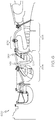
- FIG. 6 illustrates portions of an APU including a compression section 204 including a first and a second radial compressor 620, 622, a combustion section 606, and a turbine section 608.
- a bending or arcuate section 651 wherein the air flow changes abruptly from radial to axial.
- Section 651 would be another suitable location to place the fine particle separation means of the present disclosure 300, 400, 500.
- downstream of the first compressor is the second radial compressor 622, and its associated diffuser 619, subsequent to which is another arcuate section 652, which as shown in previous Figures is a suitable location to place the fine particle separation means of the present disclosure 300, 400, 500.
- the present disclosure should not be thought of as limited with regard to the placement of the fine particle separation means to any particular radial compressor stage.
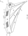
- FIG. 7 illustrates a gas turbine engine 700 employing a mixed-flow compressor 705, and a stator vane assembly 707 located downstream therefrom.
- a flow change from the radial direction to the axial direction occurs as compressed air passes from the compressor 705 to the stator vane assembly 707 and there-onward.
- any of the above-described fine particle separation means 300, 400, 500 may be implemented.
- the present disclosure has provided various embodiments of fine particle separation means for use in gas turbine engines, such as propulsion-type engines and APUs.
- the improved propulsion turbine engines and APUs exhibit improved particle separation efficiency, particularly with regard to fine sand particles.
- these engines may implement the novel particle separation means in addition to or as an alternative to conventional inlet particle separators, and may be located at positions within the engine that are different as compared to conventional inlet particle separators, for example in a compressor section (radial, mixed-flow) anywhere there is an abrupt change in flow path from the radial direction to the axial direction.
Landscapes
- Engineering & Computer Science (AREA)
- Mechanical Engineering (AREA)
- General Engineering & Computer Science (AREA)
- Chemical & Material Sciences (AREA)
- Combustion & Propulsion (AREA)
- Structures Of Non-Positive Displacement Pumps (AREA)
Claims (9)
- Moteur de turbine (100) incorporant un moyen de séparation de fines particules (300, 400), le moteur de turbine comprenant :un compresseur radial (122) qui tourne autour d'un axe longitudinal (207) et qui comprime l'air qui lui est fourni ;un diffuseur orienté radialement (204) situé en aval et radialement vers l'extérieur, par rapport à l'axe longitudinal, du compresseur radial, et qui diminue une vitesse et augmente une pression statique de l'air comprimé sortant du compresseur radial ;un chemin d'écoulement (228) positionné en aval et radialement vers l'extérieur, par rapport à l'axe longitudinal, du diffuseur, le chemin d'écoulement comprenant une paroi annulaire externe (222) et une paroi annulaire interne (220) entre lesquelles l'air comprimé s'écoule et le chemin d'écoulement comprenant un arc (232) qui redirige l'air comprimé, d'un écoulement dans une direction d'écoulement sensiblement radiale vers une direction d'écoulement sensiblement axiale ; etune fente d'extraction (306) au niveau de la paroi annulaire externe qui se connecte fluidiquement à un plénum de récupération (305), le plénum de récupération étant positionné adjacent et radialement vers l'extérieur, par rapport à l'axe longitudinal, à partir de la paroi annulaire externe au niveau d'une position axialement en aval le long du chemin d'écoulement depuis l'arc, la fente d'extraction étant également positionnée axialement en aval le long du chemin d'écoulement depuis l'arc, la fente d'extraction étant définie entre la paroi annulaire externe (222) et une paroi radiale interne (302) du plénum de récupération (305) qui est décalé radialement vers l'intérieur par rapport à la paroi annulaire externe, de sorte que la fente d'extraction occupe de 1 % à 15 % d'une surface du chemin d'écoulement, mesurée par rapport à un plan perpendiculaire à l'axe longitudinal ; etune pluralité de trous (406) le long de la paroi annulaire externe qui se connectent fluidiquement à un plénum de récupération (405), la pluralité de trous étant positionnés le long de l'arc, le plénum de récupération étant positionné adjacent à l'arc et radialement vers l'extérieur de celui-ci, par rapport à l'axe longitudinal.
- Moteur de turbine selon la revendication 1, dans lequel le chemin d'écoulement (228) comprend une partie d'un ensemble d'arrêt de tourbillonnement (206).
- Moteur de turbine selon la revendication 2, dans lequel l'ensemble d'arrêt de tourbillonnement (206) comprend une pluralité d'aubes (224) qui réduisent une composante tangentielle de l'air comprimé, la pluralité d'aubes étant situées en aval de l'arc (232).
- Moteur de turbine selon la revendication 3, dans lequel le plénum de récupération (305) est positionné adjacent à la pluralité d'aubes (224) et radialement vers l'extérieur de celles-ci, par rapport à l'axe longitudinal (207).
- Moteur de turbine selon la revendication 1, dans lequel le plénum de récupération (305) comprend un orifice de retrait de particules.
- Moteur de turbine selon la revendication 1, dans lequel la fente d'extraction (306) comprend soit un anneau axisymétrique, soit une pluralité de trous disposés de manière annulaire ayant n'importe quelle forme.
- Moteur de turbine selon la revendication 1, dans lequel les trous (406) sont inclinés circonférentiellement de 25 à 65 degrés par rapport à la paroi annulaire externe (222).
- Moteur de turbine selon la revendication 1, dans lequel les trous (406) sont inclinés axialement vers l'arrière de 5 à 20 degrés par rapport à la paroi annulaire externe (222).
- Moteur de turbine selon la revendication 1, dans lequel les trous (406) sont espacés circonférentiellement les uns des autres d'une distance supérieure ou égale à un diamètre de trou.
Applications Claiming Priority (1)
| Application Number | Priority Date | Filing Date | Title |
|---|---|---|---|
| US15/085,625 US10208628B2 (en) | 2016-03-30 | 2016-03-30 | Turbine engine designs for improved fine particle separation efficiency |
Publications (2)
| Publication Number | Publication Date |
|---|---|
| EP3225818A1 EP3225818A1 (fr) | 2017-10-04 |
| EP3225818B1 true EP3225818B1 (fr) | 2021-10-13 |
Family
ID=58158833
Family Applications (1)
| Application Number | Title | Priority Date | Filing Date |
|---|---|---|---|
| EP17157027.8A Active EP3225818B1 (fr) | 2016-03-30 | 2017-02-20 | Conceptions de moteur de turbine pour une meilleure efficacité de séparation de fines particules |
Country Status (2)
| Country | Link |
|---|---|
| US (1) | US10208628B2 (fr) |
| EP (1) | EP3225818B1 (fr) |
Families Citing this family (12)
| Publication number | Priority date | Publication date | Assignee | Title |
|---|---|---|---|---|
| DE102015219556A1 (de) | 2015-10-08 | 2017-04-13 | Rolls-Royce Deutschland Ltd & Co Kg | Diffusor für Radialverdichter, Radialverdichter und Turbomaschine mit Radialverdichter |
| US10695704B2 (en) * | 2016-07-20 | 2020-06-30 | General Electric Company | Multi-station debris separation system |
| US20180135516A1 (en) | 2016-11-16 | 2018-05-17 | Honeywell International Inc. | Scavenge methodologies for turbine engine particle separation concepts |
| US10612466B2 (en) * | 2017-09-11 | 2020-04-07 | United Technologies Corporation | Gas turbine engine active clearance control system using inlet particle separator |
| GB2572170A (en) * | 2018-03-21 | 2019-09-25 | Rolls Royce Plc | Removing entrained particles |
| US10816014B2 (en) * | 2018-07-25 | 2020-10-27 | Honeywell International Inc. | Systems and methods for turbine engine particle separation |
| US11098730B2 (en) | 2019-04-12 | 2021-08-24 | Rolls-Royce Corporation | Deswirler assembly for a centrifugal compressor |
| US11286952B2 (en) | 2020-07-14 | 2022-03-29 | Rolls-Royce Corporation | Diffusion system configured for use with centrifugal compressor |
| US11441516B2 (en) | 2020-07-14 | 2022-09-13 | Rolls-Royce North American Technologies Inc. | Centrifugal compressor assembly for a gas turbine engine with deswirler having sealing features |
| US11578654B2 (en) | 2020-07-29 | 2023-02-14 | Rolls-Royce North American Technologies Inc. | Centrifical compressor assembly for a gas turbine engine |
| US11371434B2 (en) * | 2020-08-19 | 2022-06-28 | Honeywell International Inc. | Compressor particle separator for gas turbine engine |
| FR3129442A1 (fr) * | 2021-11-24 | 2023-05-26 | Safran Aircraft Engines | Compresseur centrifuge muni d’un dispositif d’extraction de particules ingérées |
Family Cites Families (46)
| Publication number | Priority date | Publication date | Assignee | Title |
|---|---|---|---|---|
| US2709893A (en) * | 1949-08-06 | 1955-06-07 | Laval Steam Turbine Co | Gas turbine power plant with heat exchanger and cooling means |
| US3362629A (en) * | 1965-12-21 | 1968-01-09 | Carrier Corp | Centrifugal compressor |
| US3832086A (en) | 1971-11-23 | 1974-08-27 | Gen Electric | Particle separator with scroll scavenging means |
| US3993463A (en) | 1975-08-28 | 1976-11-23 | The United States Of America As Represented By The Secretary Of The Army | Particle separator for turbine engines of aircraft |
| US4292050A (en) | 1979-11-15 | 1981-09-29 | Linhardt & Associates, Inc. | Curved duct separator for removing particulate matter from a carrier gas |
| US4463552A (en) | 1981-12-14 | 1984-08-07 | United Technologies Corporation | Combined surge bleed and dust removal system for a fan-jet engine |
| US4685942A (en) | 1982-12-27 | 1987-08-11 | General Electric Company | Axial flow inlet particle separator |
| US5253472A (en) * | 1990-02-28 | 1993-10-19 | Dev Sudarshan P | Small gas turbine having enhanced fuel economy |
| US5123240A (en) | 1990-03-19 | 1992-06-23 | General Electric Co. | Method and apparatus for ejecting foreign matter from the primary flow path of a gas turbine engine |
| JP3711028B2 (ja) | 2001-02-20 | 2005-10-26 | 川崎重工業株式会社 | 異物除去構造を備えたガスタービンエンジン |
| US6499285B1 (en) | 2001-08-01 | 2002-12-31 | Rolls-Royce Corporation | Particle separator for a gas turbine engine |
| JP4464661B2 (ja) * | 2002-11-13 | 2010-05-19 | ボーグワーナー・インコーポレーテッド | 遠心圧縮機のための事前旋回発生装置 |
| DE10330471A1 (de) | 2003-07-05 | 2005-02-03 | Alstom Technology Ltd | Vorrichtung zum Abscheiden von Fremdpartikeln aus der den Laufschaufeln einer Turbine zuführbaren Kühlluft |
| WO2006059987A1 (fr) * | 2004-12-01 | 2006-06-08 | United Technologies Corporation | Séparateur de particules pour moteur à turbine en bout |
| JP4279245B2 (ja) | 2004-12-06 | 2009-06-17 | 本田技研工業株式会社 | ガスタービンエンジン |
| US7866600B2 (en) | 2005-04-13 | 2011-01-11 | Sikorsky Aircraft Corporation | Integrated engine air particle filter assembly |
| EP1896157B1 (fr) | 2005-06-20 | 2012-05-02 | Rolls-Royce North American Technologies, Inc. | Séparateur de particules pour une turbine à gaz |
| US7581397B2 (en) * | 2005-08-26 | 2009-09-01 | Honeywell International Inc. | Diffuser particle separator |
| US7874158B2 (en) | 2005-11-29 | 2011-01-25 | United Technologies Corporation | Dirt separator for compressor diffuser in gas turbine engine |
| US20070183890A1 (en) | 2006-02-09 | 2007-08-09 | Honeywell International, Inc. | Leaned deswirl vanes behind a centrifugal compressor in a gas turbine engine |
| US7569094B2 (en) | 2006-07-06 | 2009-08-04 | The United States Of America As Represented By The Secretary Of The Air Force | Method and apparatus for separating particles |
| US7802433B2 (en) | 2006-09-27 | 2010-09-28 | General Electric Company | Adaptive inertial particle separators and methods of use |
| US20080152500A1 (en) | 2006-12-20 | 2008-06-26 | Carsten Mehring | Inertial particle separator for compressor shroud bleed |
| US7678165B2 (en) | 2006-12-28 | 2010-03-16 | General Electric Company | Particle separator using boundary layer control |
| US7967554B2 (en) * | 2007-06-18 | 2011-06-28 | Honeywell International Inc. | Turbine cooling air centrifugal particle separator |
| US7927408B2 (en) | 2007-11-30 | 2011-04-19 | Honeywell International Inc. | Inlet particle separator systems and methods |
| US8092145B2 (en) * | 2008-10-28 | 2012-01-10 | Pratt & Whitney Canada Corp. | Particle separator and separating method for gas turbine engine |
| EP2382026B1 (fr) | 2008-12-26 | 2017-08-23 | Rolls-Royce North American Technologies, Inc. | Système à filtre séparateur de particules pour turbine à gaz |
| EP2379409B1 (fr) | 2008-12-30 | 2017-12-20 | Sikorsky Aircraft Corporation | Séparateur de particules d'air pour moteur |
| US8256277B2 (en) | 2009-06-11 | 2012-09-04 | United Technologies Corporation | Gas turbine engine debris monitoring arrangement |
| GB0916432D0 (en) | 2009-09-21 | 2009-10-28 | Rolls Royce Plc | Separator device |
| US20120131900A1 (en) | 2010-11-30 | 2012-05-31 | General Electric Company | Inlet particle separator system |
| US8679210B2 (en) | 2012-01-17 | 2014-03-25 | Hamilton Sundstrand Corporation | Shrouded particle separator |
| US8539775B1 (en) | 2012-03-21 | 2013-09-24 | Honeywell International Inc. | Gas turbine engines and systems and methods for removing particulate matter therefrom during operation |
| US9314723B2 (en) | 2012-09-17 | 2016-04-19 | Honeywell International Inc. | Inlet particle separator systems and methods |
| WO2014092778A1 (fr) * | 2012-12-10 | 2014-06-19 | United Technologies Corporation | Séparateur de particules à double filtration |
| US9027202B2 (en) | 2013-03-08 | 2015-05-12 | Federal Signal Corporation | Low pressure drop dust collectors |
| US9810079B2 (en) | 2013-03-15 | 2017-11-07 | General Electric Company | Cyclonic dirt separating turbine accelerator |
| US9546603B2 (en) | 2014-04-03 | 2017-01-17 | Honeywell International Inc. | Engine systems and methods for removing particles from turbine air |
| US9650916B2 (en) * | 2014-04-09 | 2017-05-16 | Honeywell International Inc. | Turbomachine cooling systems |
| US9709275B2 (en) | 2014-06-25 | 2017-07-18 | General Electric Company | Debris removal system |
| US9616373B2 (en) | 2014-10-24 | 2017-04-11 | Caterpillar Inc. | Inertial separation pre-cleaner |
| US10036319B2 (en) | 2014-10-31 | 2018-07-31 | General Electric Company | Separator assembly for a gas turbine engine |
| US10167725B2 (en) | 2014-10-31 | 2019-01-01 | General Electric Company | Engine component for a turbine engine |
| US10267179B2 (en) * | 2014-12-31 | 2019-04-23 | General Electric Company | Dirt extraction apparatus for a gas turbine engine |
| US10202903B2 (en) | 2015-09-22 | 2019-02-12 | United Technologies Corporation | Apparatus and method for air particle separation in a gas turbine engine |
-
2016
- 2016-03-30 US US15/085,625 patent/US10208628B2/en active Active
-
2017
- 2017-02-20 EP EP17157027.8A patent/EP3225818B1/fr active Active
Non-Patent Citations (1)
| Title |
|---|
| None * |
Also Published As
| Publication number | Publication date |
|---|---|
| EP3225818A1 (fr) | 2017-10-04 |
| US20170284226A1 (en) | 2017-10-05 |
| US10208628B2 (en) | 2019-02-19 |
Similar Documents
| Publication | Publication Date | Title |
|---|---|---|
| EP3225818B1 (fr) | Conceptions de moteur de turbine pour une meilleure efficacité de séparation de fines particules | |
| US11421595B2 (en) | Scavenge methodologies for turbine engine particle separation concepts | |
| US7500364B2 (en) | System for coupling flow from a centrifugal compressor to an axial combustor for gas turbines | |
| US10450951B2 (en) | Cyclonic separator for a turbine engine | |
| CA2528668C (fr) | Rotor avec deflecteurs d'air de refroidissement, et methode | |
| EP2123863B1 (fr) | Prédiffuseur pour compresseur centrifuge | |
| US20070183890A1 (en) | Leaned deswirl vanes behind a centrifugal compressor in a gas turbine engine | |
| US20170101896A1 (en) | Turbine engine, components, and methods of cooling same | |
| US10907503B2 (en) | Compressors with integrated secondary air flow systems | |
| US8602720B2 (en) | Compressors with casing treatments in gas turbine engines | |
| US8539775B1 (en) | Gas turbine engines and systems and methods for removing particulate matter therefrom during operation | |
| US11199111B2 (en) | Assembly for particle removal | |
| US10816014B2 (en) | Systems and methods for turbine engine particle separation | |
| US20210381525A1 (en) | Compressor diffuser with plasma actuators | |
| GB2084654A (en) | Cooling gas turbine engines |
Legal Events
| Date | Code | Title | Description |
|---|---|---|---|
| PUAI | Public reference made under article 153(3) epc to a published international application that has entered the european phase |
Free format text: ORIGINAL CODE: 0009012 |
|
| STAA | Information on the status of an ep patent application or granted ep patent |
Free format text: STATUS: REQUEST FOR EXAMINATION WAS MADE |
|
| 17P | Request for examination filed |
Effective date: 20170220 |
|
| AK | Designated contracting states |
Kind code of ref document: A1 Designated state(s): AL AT BE BG CH CY CZ DE DK EE ES FI FR GB GR HR HU IE IS IT LI LT LU LV MC MK MT NL NO PL PT RO RS SE SI SK SM TR |
|
| AX | Request for extension of the european patent |
Extension state: BA ME |
|
| STAA | Information on the status of an ep patent application or granted ep patent |
Free format text: STATUS: EXAMINATION IS IN PROGRESS |
|
| 17Q | First examination report despatched |
Effective date: 20190415 |
|
| STAA | Information on the status of an ep patent application or granted ep patent |
Free format text: STATUS: EXAMINATION IS IN PROGRESS |
|
| REG | Reference to a national code |
Ref country code: DE Ref legal event code: R079 Ref document number: 602017047436 Country of ref document: DE Free format text: PREVIOUS MAIN CLASS: F02C0007360000 Ipc: F04D0029700000 |
|
| RIC1 | Information provided on ipc code assigned before grant |
Ipc: F04D 29/44 20060101ALI20210527BHEP Ipc: F02C 7/00 20060101ALI20210527BHEP Ipc: F01D 25/32 20060101ALI20210527BHEP Ipc: F04D 29/42 20060101ALI20210527BHEP Ipc: F04D 29/70 20060101AFI20210527BHEP |
|
| GRAP | Despatch of communication of intention to grant a patent |
Free format text: ORIGINAL CODE: EPIDOSNIGR1 |
|
| STAA | Information on the status of an ep patent application or granted ep patent |
Free format text: STATUS: GRANT OF PATENT IS INTENDED |
|
| INTG | Intention to grant announced |
Effective date: 20210702 |
|
| GRAS | Grant fee paid |
Free format text: ORIGINAL CODE: EPIDOSNIGR3 |
|
| GRAA | (expected) grant |
Free format text: ORIGINAL CODE: 0009210 |
|
| STAA | Information on the status of an ep patent application or granted ep patent |
Free format text: STATUS: THE PATENT HAS BEEN GRANTED |
|
| AK | Designated contracting states |
Kind code of ref document: B1 Designated state(s): AL AT BE BG CH CY CZ DE DK EE ES FI FR GB GR HR HU IE IS IT LI LT LU LV MC MK MT NL NO PL PT RO RS SE SI SK SM TR |
|
| REG | Reference to a national code |
Ref country code: GB Ref legal event code: FG4D |
|
| REG | Reference to a national code |
Ref country code: CH Ref legal event code: EP |
|
| REG | Reference to a national code |
Ref country code: DE Ref legal event code: R096 Ref document number: 602017047436 Country of ref document: DE |
|
| REG | Reference to a national code |
Ref country code: IE Ref legal event code: FG4D |
|
| REG | Reference to a national code |
Ref country code: AT Ref legal event code: REF Ref document number: 1438400 Country of ref document: AT Kind code of ref document: T Effective date: 20211115 |
|
| REG | Reference to a national code |
Ref country code: LT Ref legal event code: MG9D |
|
| REG | Reference to a national code |
Ref country code: NL Ref legal event code: MP Effective date: 20211013 |
|
| REG | Reference to a national code |
Ref country code: AT Ref legal event code: MK05 Ref document number: 1438400 Country of ref document: AT Kind code of ref document: T Effective date: 20211013 |
|
| PG25 | Lapsed in a contracting state [announced via postgrant information from national office to epo] |
Ref country code: RS Free format text: LAPSE BECAUSE OF FAILURE TO SUBMIT A TRANSLATION OF THE DESCRIPTION OR TO PAY THE FEE WITHIN THE PRESCRIBED TIME-LIMIT Effective date: 20211013 Ref country code: LT Free format text: LAPSE BECAUSE OF FAILURE TO SUBMIT A TRANSLATION OF THE DESCRIPTION OR TO PAY THE FEE WITHIN THE PRESCRIBED TIME-LIMIT Effective date: 20211013 Ref country code: FI Free format text: LAPSE BECAUSE OF FAILURE TO SUBMIT A TRANSLATION OF THE DESCRIPTION OR TO PAY THE FEE WITHIN THE PRESCRIBED TIME-LIMIT Effective date: 20211013 Ref country code: BG Free format text: LAPSE BECAUSE OF FAILURE TO SUBMIT A TRANSLATION OF THE DESCRIPTION OR TO PAY THE FEE WITHIN THE PRESCRIBED TIME-LIMIT Effective date: 20220113 Ref country code: AT Free format text: LAPSE BECAUSE OF FAILURE TO SUBMIT A TRANSLATION OF THE DESCRIPTION OR TO PAY THE FEE WITHIN THE PRESCRIBED TIME-LIMIT Effective date: 20211013 |
|
| PG25 | Lapsed in a contracting state [announced via postgrant information from national office to epo] |
Ref country code: IS Free format text: LAPSE BECAUSE OF FAILURE TO SUBMIT A TRANSLATION OF THE DESCRIPTION OR TO PAY THE FEE WITHIN THE PRESCRIBED TIME-LIMIT Effective date: 20220213 Ref country code: SE Free format text: LAPSE BECAUSE OF FAILURE TO SUBMIT A TRANSLATION OF THE DESCRIPTION OR TO PAY THE FEE WITHIN THE PRESCRIBED TIME-LIMIT Effective date: 20211013 Ref country code: PT Free format text: LAPSE BECAUSE OF FAILURE TO SUBMIT A TRANSLATION OF THE DESCRIPTION OR TO PAY THE FEE WITHIN THE PRESCRIBED TIME-LIMIT Effective date: 20220214 Ref country code: PL Free format text: LAPSE BECAUSE OF FAILURE TO SUBMIT A TRANSLATION OF THE DESCRIPTION OR TO PAY THE FEE WITHIN THE PRESCRIBED TIME-LIMIT Effective date: 20211013 Ref country code: NO Free format text: LAPSE BECAUSE OF FAILURE TO SUBMIT A TRANSLATION OF THE DESCRIPTION OR TO PAY THE FEE WITHIN THE PRESCRIBED TIME-LIMIT Effective date: 20220113 Ref country code: NL Free format text: LAPSE BECAUSE OF FAILURE TO SUBMIT A TRANSLATION OF THE DESCRIPTION OR TO PAY THE FEE WITHIN THE PRESCRIBED TIME-LIMIT Effective date: 20211013 Ref country code: LV Free format text: LAPSE BECAUSE OF FAILURE TO SUBMIT A TRANSLATION OF THE DESCRIPTION OR TO PAY THE FEE WITHIN THE PRESCRIBED TIME-LIMIT Effective date: 20211013 Ref country code: HR Free format text: LAPSE BECAUSE OF FAILURE TO SUBMIT A TRANSLATION OF THE DESCRIPTION OR TO PAY THE FEE WITHIN THE PRESCRIBED TIME-LIMIT Effective date: 20211013 Ref country code: GR Free format text: LAPSE BECAUSE OF FAILURE TO SUBMIT A TRANSLATION OF THE DESCRIPTION OR TO PAY THE FEE WITHIN THE PRESCRIBED TIME-LIMIT Effective date: 20220114 Ref country code: ES Free format text: LAPSE BECAUSE OF FAILURE TO SUBMIT A TRANSLATION OF THE DESCRIPTION OR TO PAY THE FEE WITHIN THE PRESCRIBED TIME-LIMIT Effective date: 20211013 |
|
| REG | Reference to a national code |
Ref country code: DE Ref legal event code: R097 Ref document number: 602017047436 Country of ref document: DE |
|
| PG25 | Lapsed in a contracting state [announced via postgrant information from national office to epo] |
Ref country code: SM Free format text: LAPSE BECAUSE OF FAILURE TO SUBMIT A TRANSLATION OF THE DESCRIPTION OR TO PAY THE FEE WITHIN THE PRESCRIBED TIME-LIMIT Effective date: 20211013 Ref country code: SK Free format text: LAPSE BECAUSE OF FAILURE TO SUBMIT A TRANSLATION OF THE DESCRIPTION OR TO PAY THE FEE WITHIN THE PRESCRIBED TIME-LIMIT Effective date: 20211013 Ref country code: RO Free format text: LAPSE BECAUSE OF FAILURE TO SUBMIT A TRANSLATION OF THE DESCRIPTION OR TO PAY THE FEE WITHIN THE PRESCRIBED TIME-LIMIT Effective date: 20211013 Ref country code: EE Free format text: LAPSE BECAUSE OF FAILURE TO SUBMIT A TRANSLATION OF THE DESCRIPTION OR TO PAY THE FEE WITHIN THE PRESCRIBED TIME-LIMIT Effective date: 20211013 Ref country code: DK Free format text: LAPSE BECAUSE OF FAILURE TO SUBMIT A TRANSLATION OF THE DESCRIPTION OR TO PAY THE FEE WITHIN THE PRESCRIBED TIME-LIMIT Effective date: 20211013 Ref country code: CZ Free format text: LAPSE BECAUSE OF FAILURE TO SUBMIT A TRANSLATION OF THE DESCRIPTION OR TO PAY THE FEE WITHIN THE PRESCRIBED TIME-LIMIT Effective date: 20211013 |
|
| PLBE | No opposition filed within time limit |
Free format text: ORIGINAL CODE: 0009261 |
|
| STAA | Information on the status of an ep patent application or granted ep patent |
Free format text: STATUS: NO OPPOSITION FILED WITHIN TIME LIMIT |
|
| 26N | No opposition filed |
Effective date: 20220714 |
|
| PG25 | Lapsed in a contracting state [announced via postgrant information from national office to epo] |
Ref country code: MC Free format text: LAPSE BECAUSE OF FAILURE TO SUBMIT A TRANSLATION OF THE DESCRIPTION OR TO PAY THE FEE WITHIN THE PRESCRIBED TIME-LIMIT Effective date: 20211013 |
|
| REG | Reference to a national code |
Ref country code: CH Ref legal event code: PL |
|
| REG | Reference to a national code |
Ref country code: BE Ref legal event code: MM Effective date: 20220228 |
|
| GBPC | Gb: european patent ceased through non-payment of renewal fee |
Effective date: 20220220 |
|
| PG25 | Lapsed in a contracting state [announced via postgrant information from national office to epo] |
Ref country code: LU Free format text: LAPSE BECAUSE OF NON-PAYMENT OF DUE FEES Effective date: 20220220 Ref country code: AL Free format text: LAPSE BECAUSE OF FAILURE TO SUBMIT A TRANSLATION OF THE DESCRIPTION OR TO PAY THE FEE WITHIN THE PRESCRIBED TIME-LIMIT Effective date: 20211013 |
|
| PG25 | Lapsed in a contracting state [announced via postgrant information from national office to epo] |
Ref country code: SI Free format text: LAPSE BECAUSE OF FAILURE TO SUBMIT A TRANSLATION OF THE DESCRIPTION OR TO PAY THE FEE WITHIN THE PRESCRIBED TIME-LIMIT Effective date: 20211013 |
|
| PG25 | Lapsed in a contracting state [announced via postgrant information from national office to epo] |
Ref country code: FR Free format text: LAPSE BECAUSE OF NON-PAYMENT OF DUE FEES Effective date: 20220228 |
|
| PG25 | Lapsed in a contracting state [announced via postgrant information from national office to epo] |
Ref country code: LI Free format text: LAPSE BECAUSE OF NON-PAYMENT OF DUE FEES Effective date: 20220228 Ref country code: IE Free format text: LAPSE BECAUSE OF NON-PAYMENT OF DUE FEES Effective date: 20220220 Ref country code: GB Free format text: LAPSE BECAUSE OF NON-PAYMENT OF DUE FEES Effective date: 20220220 Ref country code: CH Free format text: LAPSE BECAUSE OF NON-PAYMENT OF DUE FEES Effective date: 20220228 |
|
| PG25 | Lapsed in a contracting state [announced via postgrant information from national office to epo] |
Ref country code: BE Free format text: LAPSE BECAUSE OF NON-PAYMENT OF DUE FEES Effective date: 20220228 |
|
| PG25 | Lapsed in a contracting state [announced via postgrant information from national office to epo] |
Ref country code: IT Free format text: LAPSE BECAUSE OF FAILURE TO SUBMIT A TRANSLATION OF THE DESCRIPTION OR TO PAY THE FEE WITHIN THE PRESCRIBED TIME-LIMIT Effective date: 20211013 |
|
| P01 | Opt-out of the competence of the unified patent court (upc) registered |
Effective date: 20230525 |
|
| PG25 | Lapsed in a contracting state [announced via postgrant information from national office to epo] |
Ref country code: HU Free format text: LAPSE BECAUSE OF FAILURE TO SUBMIT A TRANSLATION OF THE DESCRIPTION OR TO PAY THE FEE WITHIN THE PRESCRIBED TIME-LIMIT; INVALID AB INITIO Effective date: 20170220 |
|
| PG25 | Lapsed in a contracting state [announced via postgrant information from national office to epo] |
Ref country code: MK Free format text: LAPSE BECAUSE OF FAILURE TO SUBMIT A TRANSLATION OF THE DESCRIPTION OR TO PAY THE FEE WITHIN THE PRESCRIBED TIME-LIMIT Effective date: 20211013 Ref country code: CY Free format text: LAPSE BECAUSE OF FAILURE TO SUBMIT A TRANSLATION OF THE DESCRIPTION OR TO PAY THE FEE WITHIN THE PRESCRIBED TIME-LIMIT Effective date: 20211013 |
|
| PGFP | Annual fee paid to national office [announced via postgrant information from national office to epo] |
Ref country code: DE Payment date: 20240228 Year of fee payment: 8 |