EP3225793A1 - A fuel and oil system - Google Patents
A fuel and oil system Download PDFInfo
- Publication number
- EP3225793A1 EP3225793A1 EP17158633.2A EP17158633A EP3225793A1 EP 3225793 A1 EP3225793 A1 EP 3225793A1 EP 17158633 A EP17158633 A EP 17158633A EP 3225793 A1 EP3225793 A1 EP 3225793A1
- Authority
- EP
- European Patent Office
- Prior art keywords
- electric motor
- fuel
- oil
- motor controller
- electric
- Prior art date
- Legal status (The legal status is an assumption and is not a legal conclusion. Google has not performed a legal analysis and makes no representation as to the accuracy of the status listed.)
- Granted
Links
Images


Classifications
-
- F—MECHANICAL ENGINEERING; LIGHTING; HEATING; WEAPONS; BLASTING
- F01—MACHINES OR ENGINES IN GENERAL; ENGINE PLANTS IN GENERAL; STEAM ENGINES
- F01D—NON-POSITIVE DISPLACEMENT MACHINES OR ENGINES, e.g. STEAM TURBINES
- F01D25/00—Component parts, details, or accessories, not provided for in, or of interest apart from, other groups
- F01D25/18—Lubricating arrangements
- F01D25/20—Lubricating arrangements using lubrication pumps
-
- F—MECHANICAL ENGINEERING; LIGHTING; HEATING; WEAPONS; BLASTING
- F02—COMBUSTION ENGINES; HOT-GAS OR COMBUSTION-PRODUCT ENGINE PLANTS
- F02M—SUPPLYING COMBUSTION ENGINES IN GENERAL WITH COMBUSTIBLE MIXTURES OR CONSTITUENTS THEREOF
- F02M59/00—Pumps specially adapted for fuel-injection and not provided for in groups F02M39/00 -F02M57/00, e.g. rotary cylinder-block type of pumps
- F02M59/20—Varying fuel delivery in quantity or timing
-
- F—MECHANICAL ENGINEERING; LIGHTING; HEATING; WEAPONS; BLASTING
- F01—MACHINES OR ENGINES IN GENERAL; ENGINE PLANTS IN GENERAL; STEAM ENGINES
- F01M—LUBRICATING OF MACHINES OR ENGINES IN GENERAL; LUBRICATING INTERNAL COMBUSTION ENGINES; CRANKCASE VENTILATING
- F01M1/00—Pressure lubrication
- F01M1/02—Pressure lubrication using lubricating pumps
-
- F—MECHANICAL ENGINEERING; LIGHTING; HEATING; WEAPONS; BLASTING
- F02—COMBUSTION ENGINES; HOT-GAS OR COMBUSTION-PRODUCT ENGINE PLANTS
- F02C—GAS-TURBINE PLANTS; AIR INTAKES FOR JET-PROPULSION PLANTS; CONTROLLING FUEL SUPPLY IN AIR-BREATHING JET-PROPULSION PLANTS
- F02C7/00—Features, components parts, details or accessories, not provided for in, or of interest apart form groups F02C1/00 - F02C6/00; Air intakes for jet-propulsion plants
- F02C7/06—Arrangements of bearings; Lubricating
-
- F—MECHANICAL ENGINEERING; LIGHTING; HEATING; WEAPONS; BLASTING
- F02—COMBUSTION ENGINES; HOT-GAS OR COMBUSTION-PRODUCT ENGINE PLANTS
- F02C—GAS-TURBINE PLANTS; AIR INTAKES FOR JET-PROPULSION PLANTS; CONTROLLING FUEL SUPPLY IN AIR-BREATHING JET-PROPULSION PLANTS
- F02C7/00—Features, components parts, details or accessories, not provided for in, or of interest apart form groups F02C1/00 - F02C6/00; Air intakes for jet-propulsion plants
- F02C7/22—Fuel supply systems
-
- F—MECHANICAL ENGINEERING; LIGHTING; HEATING; WEAPONS; BLASTING
- F02—COMBUSTION ENGINES; HOT-GAS OR COMBUSTION-PRODUCT ENGINE PLANTS
- F02C—GAS-TURBINE PLANTS; AIR INTAKES FOR JET-PROPULSION PLANTS; CONTROLLING FUEL SUPPLY IN AIR-BREATHING JET-PROPULSION PLANTS
- F02C7/00—Features, components parts, details or accessories, not provided for in, or of interest apart form groups F02C1/00 - F02C6/00; Air intakes for jet-propulsion plants
- F02C7/22—Fuel supply systems
- F02C7/236—Fuel delivery systems comprising two or more pumps
-
- F—MECHANICAL ENGINEERING; LIGHTING; HEATING; WEAPONS; BLASTING
- F02—COMBUSTION ENGINES; HOT-GAS OR COMBUSTION-PRODUCT ENGINE PLANTS
- F02C—GAS-TURBINE PLANTS; AIR INTAKES FOR JET-PROPULSION PLANTS; CONTROLLING FUEL SUPPLY IN AIR-BREATHING JET-PROPULSION PLANTS
- F02C9/00—Controlling gas-turbine plants; Controlling fuel supply in air- breathing jet-propulsion plants
- F02C9/26—Control of fuel supply
-
- F—MECHANICAL ENGINEERING; LIGHTING; HEATING; WEAPONS; BLASTING
- F02—COMBUSTION ENGINES; HOT-GAS OR COMBUSTION-PRODUCT ENGINE PLANTS
- F02M—SUPPLYING COMBUSTION ENGINES IN GENERAL WITH COMBUSTIBLE MIXTURES OR CONSTITUENTS THEREOF
- F02M37/00—Apparatus or systems for feeding liquid fuel from storage containers to carburettors or fuel-injection apparatus; Arrangements for purifying liquid fuel specially adapted for, or arranged on, internal-combustion engines
- F02M37/04—Feeding by means of driven pumps
- F02M37/08—Feeding by means of driven pumps electrically driven
-
- H—ELECTRICITY
- H02—GENERATION; CONVERSION OR DISTRIBUTION OF ELECTRIC POWER
- H02K—DYNAMO-ELECTRIC MACHINES
- H02K9/00—Arrangements for cooling or ventilating
-
- H—ELECTRICITY
- H02—GENERATION; CONVERSION OR DISTRIBUTION OF ELECTRIC POWER
- H02P—CONTROL OR REGULATION OF ELECTRIC MOTORS, ELECTRIC GENERATORS OR DYNAMO-ELECTRIC CONVERTERS; CONTROLLING TRANSFORMERS, REACTORS OR CHOKE COILS
- H02P29/00—Arrangements for regulating or controlling electric motors, appropriate for both AC and DC motors
- H02P29/02—Providing protection against overload without automatic interruption of supply
- H02P29/024—Detecting a fault condition, e.g. short circuit, locked rotor, open circuit or loss of load
-
- H—ELECTRICITY
- H02—GENERATION; CONVERSION OR DISTRIBUTION OF ELECTRIC POWER
- H02P—CONTROL OR REGULATION OF ELECTRIC MOTORS, ELECTRIC GENERATORS OR DYNAMO-ELECTRIC CONVERTERS; CONTROLLING TRANSFORMERS, REACTORS OR CHOKE COILS
- H02P29/00—Arrangements for regulating or controlling electric motors, appropriate for both AC and DC motors
- H02P29/02—Providing protection against overload without automatic interruption of supply
- H02P29/024—Detecting a fault condition, e.g. short circuit, locked rotor, open circuit or loss of load
- H02P29/0241—Detecting a fault condition, e.g. short circuit, locked rotor, open circuit or loss of load the fault being an overvoltage
-
- H—ELECTRICITY
- H02—GENERATION; CONVERSION OR DISTRIBUTION OF ELECTRIC POWER
- H02P—CONTROL OR REGULATION OF ELECTRIC MOTORS, ELECTRIC GENERATORS OR DYNAMO-ELECTRIC CONVERTERS; CONTROLLING TRANSFORMERS, REACTORS OR CHOKE COILS
- H02P6/00—Arrangements for controlling synchronous motors or other dynamo-electric motors using electronic commutation dependent on the rotor position; Electronic commutators therefor
- H02P6/04—Arrangements for controlling or regulating the speed or torque of more than one motor
-
- F—MECHANICAL ENGINEERING; LIGHTING; HEATING; WEAPONS; BLASTING
- F01—MACHINES OR ENGINES IN GENERAL; ENGINE PLANTS IN GENERAL; STEAM ENGINES
- F01M—LUBRICATING OF MACHINES OR ENGINES IN GENERAL; LUBRICATING INTERNAL COMBUSTION ENGINES; CRANKCASE VENTILATING
- F01M1/00—Pressure lubrication
- F01M1/02—Pressure lubrication using lubricating pumps
- F01M2001/0207—Pressure lubrication using lubricating pumps characterised by the type of pump
- F01M2001/0215—Electrical pumps
-
- F—MECHANICAL ENGINEERING; LIGHTING; HEATING; WEAPONS; BLASTING
- F05—INDEXING SCHEMES RELATING TO ENGINES OR PUMPS IN VARIOUS SUBCLASSES OF CLASSES F01-F04
- F05D—INDEXING SCHEME FOR ASPECTS RELATING TO NON-POSITIVE-DISPLACEMENT MACHINES OR ENGINES, GAS-TURBINES OR JET-PROPULSION PLANTS
- F05D2260/00—Function
- F05D2260/84—Redundancy
-
- Y—GENERAL TAGGING OF NEW TECHNOLOGICAL DEVELOPMENTS; GENERAL TAGGING OF CROSS-SECTIONAL TECHNOLOGIES SPANNING OVER SEVERAL SECTIONS OF THE IPC; TECHNICAL SUBJECTS COVERED BY FORMER USPC CROSS-REFERENCE ART COLLECTIONS [XRACs] AND DIGESTS
- Y02—TECHNOLOGIES OR APPLICATIONS FOR MITIGATION OR ADAPTATION AGAINST CLIMATE CHANGE
- Y02T—CLIMATE CHANGE MITIGATION TECHNOLOGIES RELATED TO TRANSPORTATION
- Y02T50/00—Aeronautics or air transport
- Y02T50/60—Efficient propulsion technologies, e.g. for aircraft
Definitions
- the present disclosure concerns a fuel and oil system.
- it concerns a fuel and oil system for a gas turbine engine.
- a fuel system including a fuel pump driven at variable speed by a motor.
- the motor is controlled by a controller.
- an oil system including an oil pump driven at fixed or variable speed by a motor. Where the motor drives at variable speed it is also controlled by a controller.
- variable speed control of the fuel system is maintained throughout operation of the gas turbine engine. Therefore it is common to provide two motors and controllers to drive the fuel system in order to provide redundancy. Although variable speed control of the oil system is less critical it is still common to duplicate the oil system motor and controller for redundancy.
- Motors for fuel and oil systems may be hydraulically or mechanically driven. However, there is a desire to move towards electrically driven motors.
- a fuel and oil system comprising:
- the fuel pump is connected to and driven by the first electric motor controller and the oil pump is connected to and driven by the second electric motor controller.
- the system provides independent, fully variable control of the fuel pump and oil pump.
- this enables each of the fuel system and the oil system to operate at efficient pump speed and optimal flow rates so there is little or no excess supply and consequential spill back of fuel or oil.
- the fuel pump is connected to and driven by the second electric motor controller and the oil pump is connected to and driven by the fixed electrical drive.
- the system maintains fully variable control of the fuel pump by switching it to the second electric motor controller instead of the first electric motor controller.
- a normally-redundant variable electrical drive motor controller for the fuel pump.
- the fuel pump is connected to and driven by the first electric motor controller and the oil pump is connected to and driven by the fixed electrical drive.
- the system maintains fully variable control of the fuel pump but switches the oil pump control to the fixed electrical drive instead of the second electric motor controller.
- a normally-redundant variable electrical drive motor controller for the oil pump.
- the system provides electrical drive to the fuel pump and the oil pump in any operational mode.
- both the fuel pump and oil pump have redundancy of control.
- Advantageously variable electrical drive is maintained to the fuel pump by switching from variable to fixed electrical drive for the oil pump if one of the variable electrical motor controllers fails.
- the system includes fewer components than in known arrangements without sacrificing redundancy, and therefore safety, and whilst maintaining variable control of the fuel pump.
- the system may comprise a spill valve connected to an output of the oil pump.
- Advantageously excess oil can be spilt to an oil tank and reused.
- the oil pump can be configured to run at maximum flow rates without penalty so that it can be operated via the fixed electrical drive for extended periods of time.
- the spilt oil may be cooled before being delivered to the oil tank.
- this reduces the overall temperature of oil in the oil system.
- the first electric motor controller and the second electric motor controller may be different.
- this reduces the potential for common mode faults affecting both the first and second electric motor controllers.
- the first electric motor controller and the second electric motor controller may be the same type.
- the electric motor controllers are interchangeable which reduces the part count and thus the required spare part stock. It also ensures that the first and second electric motor controllers are wholly substitutable and therefore provides good redundancy.
- the system may further comprise a cooling arrangement.
- the cooling system may comprise a first cooling loop arranged to cool the first electric motor controller and a second cooling loop arranged to cool the second electric motor controller.
- each cooling loop may be optimised to the electric motor controller it is arranged to cool.
- the cooling system may comprise a common cooling loop arranged to cool both the first electric motor controller and the second electric motor controller.
- the common cooling loop may comprise fewer parts than two separate loops.
- gas turbine engine comprising a fuel and oil system as described above.
- diesel engine comprising a fuel and oil system as described above.
- a gas turbine engine is generally indicated at 10, having a principal and rotational axis 11.
- the engine 10 comprises, in axial flow series, an air intake 12, a propulsive fan 13, an intermediate pressure compressor 14, a high-pressure compressor 15, combustion equipment 16, a high-pressure turbine 17, an intermediate pressure turbine 18, a low-pressure turbine 19 and an exhaust nozzle 20.
- a nacelle 21 generally surrounds the engine 10 and defines both the intake 12 and the exhaust nozzle 20.
- the gas turbine engine 10 works in the conventional manner so that air entering the intake 12 is accelerated by the fan 13 to produce two air flows: a first air flow into the intermediate pressure compressor 14 and a second air flow which passes through a bypass duct 22 to provide propulsive thrust.
- the intermediate pressure compressor 14 compresses the air flow directed into it before delivering that air to the high pressure compressor 15 where further compression takes place.
- the compressed air exhausted from the high-pressure compressor 15 is directed into the combustion equipment 16 where it is mixed with fuel and the mixture combusted.
- the resultant hot combustion products then expand through, and thereby drive the high, intermediate and low-pressure turbines 17, 18, 19 before being exhausted through the nozzle 20 to provide additional propulsive thrust.
- the high 17, intermediate 18 and low 19 pressure turbines drive respectively the high pressure compressor 15, intermediate pressure compressor 14 and fan 13, each by suitable interconnecting shaft.
- gas turbine engines to which the present disclosure may be applied may have alternative configurations.
- such engines may have an alternative number of interconnecting shafts (e.g. two) and/or an alternative number of compressors and/or turbines.
- the engine may comprise a gearbox provided in the drive train from a turbine to a compressor and/or fan.
- FIG. 2 shows a commonly used dual redundant motor control system 26.
- a fuel pump 28 is driven by an electric motor (not shown).
- An oil pump 30 is driven by an electric motor (not shown).
- a first power bus 32 is arranged to provide electrical power.
- a second power bus 34 is arranged to provide electrical power independently of the first power bus 32.
- the motor for the fuel pump 28 is controlled by a first electric motor controller 36 or a second electric motor controller 38.
- the first electric motor controller 36 is powered by the first power bus 32 whereas the second electric motor controller 38 is powered by the second power bus 34.
- first and second electric motor controllers 36, 38 is usually used to drive the electric motor of the fuel pump 28 and the other of the first and second electric motor controllers 36, 38 is normally dormant but is available to take over control in the event of failure of the usually driving electric motor controller 36, 38.
- the fuel pump 28 has redundant motor control.
- the motor for the oil pump 30 is controlled by a third electric motor controller 40 or a fourth electric motor controller 42.
- the third electric motor controller 40 is powered by the first power bus 32 whereas the fourth electric motor controller 42 is powered by the second power bus 34.
- one of the third and fourth electric motor controllers 40, 42 is usually used to drive the electric motor of the oil pump 30 and the other of the third and fourth electric motor controllers 40, 42 is normally dormant but is available to take over control in the event of failure of the usually driving electric motor controller 40, 42.
- the oil pump 30 thus also has redundant motor control.
- the motor control system 26 is therefore a dual redundant system.
- the fuel and oil system 50 is illustrated in Figure 3 .
- the fuel pump 28 is driven by an electric fuel motor 52.
- the oil pump 30 is similarly driven by an electric oil motor 54.
- Part of the oil system 56 is shown.
- An oil tank 58 delivers oil to the oil pump 30 which pumps the oil to the engine 10, arrow 62.
- a spill valve 60 is opened to spill some of the oil back to the oil tank 58, which incurs some additional heating of the oil.
- the oil system 56 is generally closed loop. Therefore, the oil tank 58 is supplied from scavenge of oil which has been used in the engine 10, as indicated by arrow 64.
- the fuel system is not shown for simplicity. Broadly fuel is supplied from a fuel tank to the fuel pump 28 which delivers fuel to combustor 16 of the engine 10.
- the fuel system is open loop, although if excess fuel is provided to the fuel pump 28 it can be spilled back to the fuel tank. It is beneficial not to oversupply fuel to the fuel pump 28 as the act of pumping it works the fuel and therefore heats it and increases the cooling requirement in the fuel and oil system 52.
- a power source 66 is illustrated as two busbars. Other forms of suitable power source 66 can be substituted with equal felicity.
- a first electric motor controller 68 is connected to the power source 66.
- the first electric motor controller 68 is a variable controller. It is configured to supply electrical drive at a variable output speed or frequency.
- the first electric motor controller 68 is selectively electrically coupled to or connected to the electric fuel motor 52 to drive the motor 52 and thence the fuel pump 28 at a variable speed as required by the engine control system.
- a first switch 72 may be provided between the first electric motor controller 68 and the electric fuel motor 52. Closing the first switch 72 electrically couples or connects the first electric motor controller 68 to the electric fuel motor 52 while opening the first switch 72 electrically isolates the electric fuel motor 52 from the first electric motor controller 68.
- a second electric motor controller 70 is connected to the power source 66.
- the second electric motor controller 70 is also a variable controller. It is configured to supply electrical drive at a variable output speed or frequency.
- the second electric motor controller 70 is selectively electrically coupled to or connected to the electric oil motor 54 to drive the motor 54 and thence the oil pump 30 at a variable speed as required by the engine control system.
- a second switch 74 may be provided between the second electric motor controller 70 and the electric oil motor 54. Closing the second switch 74 electrically couples or connects the second electric motor controller 70 to the electric oil motor 54 while opening the second switch 74 electrically isolates the electric oil motor 54 from the second electric motor controller 70.
- the second electric motor controller 70 is also selectively electrically coupled to or connected to the electric fuel motor 52 to drive the motor 52 and thence the fuel pump 28 at a variable speed. In the event of a fault in the first electric motor controller 68 the second electric motor controller 70 can be coupled to the electric fuel motor 52 to provide the variable electrical drive so that fully variable control is possible in all operational conditions.
- the first electric motor controller 68 can be isolated from the electric fuel motor 52 by opening first switch 72.
- the second electric motor controller 70 can be electrically coupled or connected to the electric fuel motor 52 by closing a third switch 78.
- the fuel and oil system 50 also includes a fixed electrical drive 76.
- the fixed electrical drive 76 is selectively electrically coupled or connected to the electric oil motor 54 to drive the motor 54 and thence the oil pump 30 at a constant speed.
- the fixed electrical drive 76 may comprise, as illustrated, a pair of switches to directly electrically couple or connect the power source 66 to the electric oil motor 54. It is less efficient to drive the oil pump 30 at constant speed because excess oil is pumped and therefore heated which must be spilt through the spill valve 60 back to the oil tank 58. Preferably the spilt oil should be cooled before being delivered back to the oil tank 58 to reduce the overall temperature of the oil in the oil system 56.
- Figure 4 shows the system of Figure 3 in a first operating configuration.
- the electric fuel motor 52 is electrically coupled to or connected to the first electric motor controller 68 via closed first switch 72.
- the electric oil motor 54 is electrically coupled to or connected to the second electric motor controller 70 via closed second switch 74.
- Third switch 78 is open so that there is no electrical connection from the second electric motor controller 70 to the electric fuel motor 52.
- the fixed electrical drive 76 is electrically disconnected or decoupled from the electric oil motor 54, for example by opening the switches.
- the fuel and oil system 50 provides independent, fully variable control of the electric fuel motor 52 and fuel pump 28, and of the electric oil motor 54 and oil pump 30.
- this enables each part of the system, the fuel system and the oil system 56, to be operated at an efficient pump speed and to minimise cooling requirements by minimising the excess supply and consequential spill back of fuel or oil.
- Figure 5 shows the system of Figure 3 in a second operating configuration.
- the second configuration there is a fault in the first electric motor controller 68, which is therefore unable to control the electric fuel motor 52.
- the electrical connection to the faulty first electric motor controller 68 is isolated by opening the first switch 72 and the electric fuel motor 52 is instead electrically coupled or connected to the second electric motor controller 70 by closing the third switch 78.
- the second switch 74 is opened to isolate the electric oil motor 54 from the second electric motor controller 70, so that the second electric motor controller 70 is not overloaded, and the electric oil motor 54 is electrically coupled or connected to the fixed electrical drive 76, by closing the switches.
- both the fuel system and oil system 56 have redundancy of control.
- the second configuration sacrifices variable control of the oil system 56 in order to maintain fully variable control of the electric fuel motor 52 and fuel pump 28 without having to provide a normally-redundant variable output motor controller for the fuel system.
- FIG. 6 shows the fuel and oil system 50 in a third configuration.
- the third configuration there is a fault in the second electric motor controller 70, which is therefore unable to control the electric oil motor 54.
- the first electric motor controller 68 is unaffected and therefore fully variable control of the electric fuel motor 52 is provided, as in the first configuration, by the first electric motor controller 68 through closed first switch 72.
- Both the second and third switches 74, 78 are opened to isolate the faulty second electric motor controller 70 from the electric fuel motor 52 and from the electric oil motor 54.
- the fixed electrical drive 76 is electrically coupled or connected to the electric oil motor 54, for example by closing the switches, in order that the electric oil motor 54 can drive the oil pump 30 at constant speed.
- the fuel and oil system 50 as described has operating configurations suitable for normal running and which account for failure of the first or second electric motor controllers 68, 70.
- each operating configuration fully variable control of the fuel system is maintained.
- variable control of the oil system 56 is replaced by fixed speed control of the oil pump 30 because the oil can be more easily cooled.
- the fuel and oil system 50 as described requires only two variable output electric motor controllers 68, 70 compared to the arrangement described with respect to Figure 2 which has four such motor controllers 36, 38, 40, 42. Consequently there is a benefit in terms of weight, cooling requirements, part count and complexity without sacrificing redundancy in the control of each part of the system 50.
- the fuel pump 28 and oil pump 30 are controlled independently so each can be driven at an optimal speed in the first configuration.
- the fuel pump 28 can also be driven at an optimal speed in the second and third configurations where one or the other of the first and second electric motor controllers 68, 70 is faulty.
- the fixed electrical drive 76 is set at a size to provide sufficient electrical power to the electric oil motor 54 to drive the oil pump 30 for the most severe operating conditions. Where the fuel and oil system 50 forms part of a gas turbine engine 10 to power an aircraft the fastest (most severe) speed requirement for the oil pump 30 is at maximum take-off thrust. Thus both the fixed electrical drive 76 and the electric oil motor 54 are sized to supply sufficient power to operate the oil pump 30 at the maximum take-off speed for extended operation. Advantageously this ensures that where the fuel and oil system 50 must operate in the second or third configuration due to a fault in the first or second electric motor controller 68, 70 it is not necessary to restrict operation of the gas turbine engine 10. Alternatively a smaller fixed electrical drive 76 may be provided and suitable restrictions placed on operation of the gas turbine engine 10 to compensate when the fuel and oil system 50 is operated in the second or third configurations.
- a coarse level of speed control can be provided for the oil pump 30 by the fixed electrical drive 76.
- the fixed electrical drive 76 may supply one or more of the phases of the power source 66 to the electric oil motor 54 and therefore provide more than one constant power level to drive the oil pump 30.
- the oil pump 30 can therefore be driven at a finite number of speeds corresponding to the number of phases available in the power source 66 which can be switched in or out by the fixed electrical drive 76. This contrasts to the operation in the first configuration where the oil pump 30 is controlled fully variably.
- the oversupply of oil, and consequent spill back and cooling requirements can be reduced.
- Some oversupply is still expected since it is unlikely that the available constant speeds corresponding to the phases of the power source 66 will match all (or even any) of the desired speeds for operation of the oil pump 30.
- a single phase of the power source 66 could be arranged to correspond to the minimum speed requirement of the oil pump 30.
- the fuel and oil system 50 may include a controller or control function which actively manages opening and closing of the first, second and third switches 72, 74, 78 and electrical coupling or connection of the fixed electrical drive 76.
- this may smooth the input to the electric fuel motor 52 during switching between the first and second electric motor controllers 68, 70 and/or may smooth the input to the electric oil motor 54 during switching between the second electric motor controller 70 and the fixed electrical drive 76.
- the electrical coupling or connection, and decoupling or disconnection, of the electric fuel and oil motors 52, 54 to the first and second electric motor controllers 68, 70 and fixed electrical drive 76 may be managed passively. That means that the electric fuel motor 52 may be arranged or configured to try to draw power from the second electric motor controller 70 when no power or a reduced amount of power is being supplied from the first electric motor controller 68, and similarly the electric oil motor 54 may be arranged or configured to try to draw power from the fixed electrical drive 76 when no power or a reduced amount of power is being supplied from the second electric motor controller 70.
- the first electric motor controller 68 may be identical to the second electric motor controller 70 so that they are entirely interchangeable. Advantageously this reduces the part count of the fuel and oil system 50. Advantageously it also ensures that the controllers 68, 70 are wholly substitutable and therefore provide excellent redundancy.
- the first electric motor controller 68 may differ from the second electric motor controller 70.
- the available power output of each controller 68, 70 may be the same to provide the redundancy to permit either controller 68, 70 to drive either the electric fuel motor 52 or the electric oil motor 54.
- the second electric motor controller 70 may have a larger maximum power output than the first electric motor controller 68 in order to absorb any demand surge during switching from controlling the electric oil motor 54 to controlling the electric fuel motor 52 (switching from the first to the second configurations of the fuel and oil system 50).
- dissimilar electric motor controllers 68, 70 common mode failures are reduced or eliminated. Thus where an external event causes failure of the first electric motor controller 68 the second electric motor controller 70 may not be affected and vice versa.
- the fuel and oil system 50 finds particular applicability in a gas turbine engine 10 for powering an aircraft because it provides full redundancy with significant weight reduction compared to the motor control system 26 shown in Figure 2 . However, it also finds application in gas turbine engines 10 used for other purposes, for example for marine and industrial applications; and in gas and diesel engines.
- the fuel and oil system 50 also finds application in other industries in which two separate fluid pumping systems each have variable speed control of the pumps but one system can tolerate fixed speed control.
Landscapes
- Engineering & Computer Science (AREA)
- Chemical & Material Sciences (AREA)
- Combustion & Propulsion (AREA)
- Mechanical Engineering (AREA)
- General Engineering & Computer Science (AREA)
- Power Engineering (AREA)
- Lubrication Of Internal Combustion Engines (AREA)
Abstract
Description
- The present disclosure concerns a fuel and oil system. In particular, but not exclusively, it concerns a fuel and oil system for a gas turbine engine.
- In a gas turbine engine it is known to have a fuel system including a fuel pump driven at variable speed by a motor. The motor is controlled by a controller. Similarly it is common to have an oil system including an oil pump driven at fixed or variable speed by a motor. Where the motor drives at variable speed it is also controlled by a controller.
- Generally it is considered critical that the variable speed control of the fuel system is maintained throughout operation of the gas turbine engine. Therefore it is common to provide two motors and controllers to drive the fuel system in order to provide redundancy. Although variable speed control of the oil system is less critical it is still common to duplicate the oil system motor and controller for redundancy.
- Motors for fuel and oil systems may be hydraulically or mechanically driven. However, there is a desire to move towards electrically driven motors.
- According to a first aspect of the present invention there is provided a fuel and oil system comprising:
- a fuel pump;
- an oil pump;
- a first electric motor controller configured to supply a variable electrical drive;
- a second electric motor controller configured to supply a variable electrical drive; and
- a fixed electrical drive;
- In a first configuration of the system the fuel pump is connected to and driven by the first electric motor controller and the oil pump is connected to and driven by the second electric motor controller. Advantageously the system provides independent, fully variable control of the fuel pump and oil pump. Advantageously this enables each of the fuel system and the oil system to operate at efficient pump speed and optimal flow rates so there is little or no excess supply and consequential spill back of fuel or oil.
- In a second configuration of the system the fuel pump is connected to and driven by the second electric motor controller and the oil pump is connected to and driven by the fixed electrical drive. Advantageously, when the first electric motor controller is faulty and so unable to control the fuel pump, the system maintains fully variable control of the fuel pump by switching it to the second electric motor controller instead of the first electric motor controller. Advantageously there is no requirement for a normally-redundant variable electrical drive motor controller for the fuel pump.
- In a third configuration of the system the fuel pump is connected to and driven by the first electric motor controller and the oil pump is connected to and driven by the fixed electrical drive. Advantageously, when the second electric motor controller is faulty and so unable to control the oil pump, the system maintains fully variable control of the fuel pump but switches the oil pump control to the fixed electrical drive instead of the second electric motor controller. Advantageously there is no requirement for a normally-redundant variable electrical drive motor controller for the oil pump.
- Advantageously the system provides electrical drive to the fuel pump and the oil pump in any operational mode. Advantageously both the fuel pump and oil pump have redundancy of control. Advantageously variable electrical drive is maintained to the fuel pump by switching from variable to fixed electrical drive for the oil pump if one of the variable electrical motor controllers fails. Advantageously the system includes fewer components than in known arrangements without sacrificing redundancy, and therefore safety, and whilst maintaining variable control of the fuel pump.
- The system may comprise a spill valve connected to an output of the oil pump. Advantageously excess oil can be spilt to an oil tank and reused. Advantageously the oil pump can be configured to run at maximum flow rates without penalty so that it can be operated via the fixed electrical drive for extended periods of time. The spilt oil may be cooled before being delivered to the oil tank. Advantageously this reduces the overall temperature of oil in the oil system.
- The first electric motor controller and the second electric motor controller may be different. Advantageously this reduces the potential for common mode faults affecting both the first and second electric motor controllers. Alternatively the first electric motor controller and the second electric motor controller may be the same type. Advantageously this means the electric motor controllers are interchangeable which reduces the part count and thus the required spare part stock. It also ensures that the first and second electric motor controllers are wholly substitutable and therefore provides good redundancy.
- The system may further comprise a cooling arrangement. The cooling system may comprise a first cooling loop arranged to cool the first electric motor controller and a second cooling loop arranged to cool the second electric motor controller. Advantageously each cooling loop may be optimised to the electric motor controller it is arranged to cool. Alternatively the cooling system may comprise a common cooling loop arranged to cool both the first electric motor controller and the second electric motor controller. Advantageously the common cooling loop may comprise fewer parts than two separate loops.
- There is also provided a gas turbine engine comprising a fuel and oil system as described above. There is also provided a diesel engine comprising a fuel and oil system as described above.
- The skilled person will appreciate that except where mutually exclusive, a feature described in relation to any one of the above aspects may be applied mutatis mutandis to any other aspect. Furthermore except where mutually exclusive any feature described herein may be applied to any aspect and/or combined with any other feature described herein.
- Embodiments will now be described by way of example only, with reference to the Figures, in which:
-
Figure 1 is a sectional side view of a gas turbine engine; -
Figure 2 is a schematic illustration of a dual redundant fuel and oil system; -
Figure 3 is a schematic illustration of a fuel and oil system as described herein; -
Figure 4 is a schematic illustration of the system ofFigure 3 in a first configuration; -
Figure 5 is a schematic illustration of the system ofFigure 3 in a second configuration; -
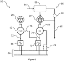
Figure 6 is a schematic illustration of the system ofFigure 3 in a third configuration. - With reference to
Figure 1 , a gas turbine engine is generally indicated at 10, having a principal androtational axis 11. Theengine 10 comprises, in axial flow series, anair intake 12, apropulsive fan 13, anintermediate pressure compressor 14, a high-pressure compressor 15,combustion equipment 16, a high-pressure turbine 17, anintermediate pressure turbine 18, a low-pressure turbine 19 and anexhaust nozzle 20. Anacelle 21 generally surrounds theengine 10 and defines both theintake 12 and theexhaust nozzle 20. - The
gas turbine engine 10 works in the conventional manner so that air entering theintake 12 is accelerated by thefan 13 to produce two air flows: a first air flow into theintermediate pressure compressor 14 and a second air flow which passes through abypass duct 22 to provide propulsive thrust. Theintermediate pressure compressor 14 compresses the air flow directed into it before delivering that air to thehigh pressure compressor 15 where further compression takes place. - The compressed air exhausted from the high-
pressure compressor 15 is directed into thecombustion equipment 16 where it is mixed with fuel and the mixture combusted. The resultant hot combustion products then expand through, and thereby drive the high, intermediate and low-pressure turbines nozzle 20 to provide additional propulsive thrust. The high 17, intermediate 18 and low 19 pressure turbines drive respectively thehigh pressure compressor 15,intermediate pressure compressor 14 andfan 13, each by suitable interconnecting shaft. - Other gas turbine engines to which the present disclosure may be applied may have alternative configurations. By way of example such engines may have an alternative number of interconnecting shafts (e.g. two) and/or an alternative number of compressors and/or turbines. Further the engine may comprise a gearbox provided in the drive train from a turbine to a compressor and/or fan.
-
Figure 2 shows a commonly used dual redundantmotor control system 26. Afuel pump 28 is driven by an electric motor (not shown). Anoil pump 30 is driven by an electric motor (not shown). Afirst power bus 32 is arranged to provide electrical power. Asecond power bus 34 is arranged to provide electrical power independently of thefirst power bus 32. The motor for thefuel pump 28 is controlled by a firstelectric motor controller 36 or a secondelectric motor controller 38. The firstelectric motor controller 36 is powered by thefirst power bus 32 whereas the secondelectric motor controller 38 is powered by thesecond power bus 34. Thus one of the first and secondelectric motor controllers fuel pump 28 and the other of the first and secondelectric motor controllers electric motor controller fuel pump 28 has redundant motor control. - Similarly the motor for the
oil pump 30 is controlled by a thirdelectric motor controller 40 or a fourthelectric motor controller 42. The thirdelectric motor controller 40 is powered by thefirst power bus 32 whereas the fourthelectric motor controller 42 is powered by thesecond power bus 34. Thus one of the third and fourthelectric motor controllers oil pump 30 and the other of the third and fourthelectric motor controllers electric motor controller oil pump 30 thus also has redundant motor control. Themotor control system 26 is therefore a dual redundant system. - In a
gas turbine engine 10, particularly agas turbine engine 10 used to power an aircraft, it is beneficial to reduce the number ofmotor controllers oil system 50 of the present invention addresses these considerations. - The fuel and
oil system 50 is illustrated inFigure 3 . Thefuel pump 28 is driven by anelectric fuel motor 52. Theoil pump 30 is similarly driven by anelectric oil motor 54. Part of theoil system 56 is shown. Anoil tank 58 delivers oil to theoil pump 30 which pumps the oil to theengine 10,arrow 62. When an excess of oil is pumped aspill valve 60 is opened to spill some of the oil back to theoil tank 58, which incurs some additional heating of the oil. Theoil system 56 is generally closed loop. Therefore, theoil tank 58 is supplied from scavenge of oil which has been used in theengine 10, as indicated byarrow 64. - The fuel system is not shown for simplicity. Broadly fuel is supplied from a fuel tank to the
fuel pump 28 which delivers fuel to combustor 16 of theengine 10. The fuel system is open loop, although if excess fuel is provided to thefuel pump 28 it can be spilled back to the fuel tank. It is beneficial not to oversupply fuel to thefuel pump 28 as the act of pumping it works the fuel and therefore heats it and increases the cooling requirement in the fuel andoil system 52. - A
power source 66 is illustrated as two busbars. Other forms ofsuitable power source 66 can be substituted with equal felicity. - A first
electric motor controller 68 is connected to thepower source 66. The firstelectric motor controller 68 is a variable controller. It is configured to supply electrical drive at a variable output speed or frequency. The firstelectric motor controller 68 is selectively electrically coupled to or connected to theelectric fuel motor 52 to drive themotor 52 and thence thefuel pump 28 at a variable speed as required by the engine control system. Afirst switch 72 may be provided between the firstelectric motor controller 68 and theelectric fuel motor 52. Closing thefirst switch 72 electrically couples or connects the firstelectric motor controller 68 to theelectric fuel motor 52 while opening thefirst switch 72 electrically isolates theelectric fuel motor 52 from the firstelectric motor controller 68. - A second
electric motor controller 70 is connected to thepower source 66. The secondelectric motor controller 70 is also a variable controller. It is configured to supply electrical drive at a variable output speed or frequency. The secondelectric motor controller 70 is selectively electrically coupled to or connected to theelectric oil motor 54 to drive themotor 54 and thence theoil pump 30 at a variable speed as required by the engine control system. Asecond switch 74 may be provided between the secondelectric motor controller 70 and theelectric oil motor 54. Closing thesecond switch 74 electrically couples or connects the secondelectric motor controller 70 to theelectric oil motor 54 while opening thesecond switch 74 electrically isolates theelectric oil motor 54 from the secondelectric motor controller 70. - The second
electric motor controller 70 is also selectively electrically coupled to or connected to theelectric fuel motor 52 to drive themotor 52 and thence thefuel pump 28 at a variable speed. In the event of a fault in the firstelectric motor controller 68 the secondelectric motor controller 70 can be coupled to theelectric fuel motor 52 to provide the variable electrical drive so that fully variable control is possible in all operational conditions. The firstelectric motor controller 68 can be isolated from theelectric fuel motor 52 by openingfirst switch 72. The secondelectric motor controller 70 can be electrically coupled or connected to theelectric fuel motor 52 by closing athird switch 78. - The fuel and
oil system 50 also includes a fixedelectrical drive 76. The fixedelectrical drive 76 is selectively electrically coupled or connected to theelectric oil motor 54 to drive themotor 54 and thence theoil pump 30 at a constant speed. The fixedelectrical drive 76 may comprise, as illustrated, a pair of switches to directly electrically couple or connect thepower source 66 to theelectric oil motor 54. It is less efficient to drive theoil pump 30 at constant speed because excess oil is pumped and therefore heated which must be spilt through thespill valve 60 back to theoil tank 58. Preferably the spilt oil should be cooled before being delivered back to theoil tank 58 to reduce the overall temperature of the oil in theoil system 56. -
Figure 4 shows the system ofFigure 3 in a first operating configuration. In the first configuration there are no faults in the fuel andoil system 50. Theelectric fuel motor 52 is electrically coupled to or connected to the firstelectric motor controller 68 via closedfirst switch 72. Theelectric oil motor 54 is electrically coupled to or connected to the secondelectric motor controller 70 via closedsecond switch 74.Third switch 78 is open so that there is no electrical connection from the secondelectric motor controller 70 to theelectric fuel motor 52. The fixedelectrical drive 76 is electrically disconnected or decoupled from theelectric oil motor 54, for example by opening the switches. - In the first configuration the fuel and
oil system 50 provides independent, fully variable control of theelectric fuel motor 52 andfuel pump 28, and of theelectric oil motor 54 andoil pump 30. Advantageously this enables each part of the system, the fuel system and theoil system 56, to be operated at an efficient pump speed and to minimise cooling requirements by minimising the excess supply and consequential spill back of fuel or oil. -
Figure 5 shows the system ofFigure 3 in a second operating configuration. In the second configuration there is a fault in the firstelectric motor controller 68, which is therefore unable to control theelectric fuel motor 52. In order to maintain fully variable control of theelectric fuel motor 52 the electrical connection to the faulty firstelectric motor controller 68 is isolated by opening thefirst switch 72 and theelectric fuel motor 52 is instead electrically coupled or connected to the secondelectric motor controller 70 by closing thethird switch 78. At the same time thesecond switch 74 is opened to isolate theelectric oil motor 54 from the secondelectric motor controller 70, so that the secondelectric motor controller 70 is not overloaded, and theelectric oil motor 54 is electrically coupled or connected to the fixedelectrical drive 76, by closing the switches. - In the second configuration, therefore, there is fully variable control of the
electric fuel motor 52 andfuel pump 28 but theoil pump 30 is operated at fixed speed by theelectric oil motor 54. Advantageously both the fuel system andoil system 56 have redundancy of control. The second configuration sacrifices variable control of theoil system 56 in order to maintain fully variable control of theelectric fuel motor 52 andfuel pump 28 without having to provide a normally-redundant variable output motor controller for the fuel system. -
Figure 6 shows the fuel andoil system 50 in a third configuration. In the third configuration there is a fault in the secondelectric motor controller 70, which is therefore unable to control theelectric oil motor 54. The firstelectric motor controller 68 is unaffected and therefore fully variable control of theelectric fuel motor 52 is provided, as in the first configuration, by the firstelectric motor controller 68 through closedfirst switch 72. Both the second andthird switches electric motor controller 70 from theelectric fuel motor 52 and from theelectric oil motor 54. Instead the fixedelectrical drive 76 is electrically coupled or connected to theelectric oil motor 54, for example by closing the switches, in order that theelectric oil motor 54 can drive theoil pump 30 at constant speed. - In the third configuration, therefore, there is fully variable control of the
electric fuel motor 52 andfuel pump 28 but theoil pump 30 is operated at fixed speed by theelectric oil motor 54. Advantageously both the fuel system andoil system 56 have redundancy of control. The third configuration sacrifices variable control of theoil system 56 and so does not have to provide a normally-redundant variable output motor controller for theoil system 56. - Advantageously the fuel and
oil system 50 as described has operating configurations suitable for normal running and which account for failure of the first or secondelectric motor controllers oil system 56 is replaced by fixed speed control of theoil pump 30 because the oil can be more easily cooled. - Advantageously the fuel and
oil system 50 as described requires only two variable outputelectric motor controllers Figure 2 which has foursuch motor controllers system 50. Thefuel pump 28 andoil pump 30 are controlled independently so each can be driven at an optimal speed in the first configuration. Thefuel pump 28 can also be driven at an optimal speed in the second and third configurations where one or the other of the first and secondelectric motor controllers - The fixed
electrical drive 76 is set at a size to provide sufficient electrical power to theelectric oil motor 54 to drive theoil pump 30 for the most severe operating conditions. Where the fuel andoil system 50 forms part of agas turbine engine 10 to power an aircraft the fastest (most severe) speed requirement for theoil pump 30 is at maximum take-off thrust. Thus both the fixedelectrical drive 76 and theelectric oil motor 54 are sized to supply sufficient power to operate theoil pump 30 at the maximum take-off speed for extended operation. Advantageously this ensures that where the fuel andoil system 50 must operate in the second or third configuration due to a fault in the first or secondelectric motor controller gas turbine engine 10. Alternatively a smaller fixedelectrical drive 76 may be provided and suitable restrictions placed on operation of thegas turbine engine 10 to compensate when the fuel andoil system 50 is operated in the second or third configurations. - Where the
power source 66 is multiphase, for example three-phase, a coarse level of speed control can be provided for theoil pump 30 by the fixedelectrical drive 76. The fixedelectrical drive 76 may supply one or more of the phases of thepower source 66 to theelectric oil motor 54 and therefore provide more than one constant power level to drive theoil pump 30. Theoil pump 30 can therefore be driven at a finite number of speeds corresponding to the number of phases available in thepower source 66 which can be switched in or out by the fixedelectrical drive 76. This contrasts to the operation in the first configuration where theoil pump 30 is controlled fully variably. By providing more than one constant speed of operation of theoil pump 30 in the second and third configurations of the fuel andoil system 50 the oversupply of oil, and consequent spill back and cooling requirements, can be reduced. Some oversupply is still expected since it is unlikely that the available constant speeds corresponding to the phases of thepower source 66 will match all (or even any) of the desired speeds for operation of theoil pump 30. Advantageously a single phase of thepower source 66 could be arranged to correspond to the minimum speed requirement of theoil pump 30. - Optionally the fuel and
oil system 50 may include a controller or control function which actively manages opening and closing of the first, second andthird switches electrical drive 76. Advantageously this may smooth the input to theelectric fuel motor 52 during switching between the first and secondelectric motor controllers electric oil motor 54 during switching between the secondelectric motor controller 70 and the fixedelectrical drive 76. - Alternatively the electrical coupling or connection, and decoupling or disconnection, of the electric fuel and
oil motors electric motor controllers electrical drive 76 may be managed passively. That means that theelectric fuel motor 52 may be arranged or configured to try to draw power from the secondelectric motor controller 70 when no power or a reduced amount of power is being supplied from the firstelectric motor controller 68, and similarly theelectric oil motor 54 may be arranged or configured to try to draw power from the fixedelectrical drive 76 when no power or a reduced amount of power is being supplied from the secondelectric motor controller 70. - The first
electric motor controller 68 may be identical to the secondelectric motor controller 70 so that they are entirely interchangeable. Advantageously this reduces the part count of the fuel andoil system 50. Advantageously it also ensures that thecontrollers - Alternatively the first
electric motor controller 68 may differ from the secondelectric motor controller 70. The available power output of eachcontroller controller electric fuel motor 52 or theelectric oil motor 54. The secondelectric motor controller 70 may have a larger maximum power output than the firstelectric motor controller 68 in order to absorb any demand surge during switching from controlling theelectric oil motor 54 to controlling the electric fuel motor 52 (switching from the first to the second configurations of the fuel and oil system 50). Advantageously, by providing dissimilarelectric motor controllers electric motor controller 68 the secondelectric motor controller 70 may not be affected and vice versa. - The fuel and
oil system 50 finds particular applicability in agas turbine engine 10 for powering an aircraft because it provides full redundancy with significant weight reduction compared to themotor control system 26 shown inFigure 2 . However, it also finds application ingas turbine engines 10 used for other purposes, for example for marine and industrial applications; and in gas and diesel engines. - The fuel and
oil system 50 also finds application in other industries in which two separate fluid pumping systems each have variable speed control of the pumps but one system can tolerate fixed speed control. - It will be understood that the invention is not limited to the embodiments above-described and various modifications and improvements can be made without departing from the concepts described herein. Except where mutually exclusive, any of the features may be employed separately or in combination with any other features and the disclosure extends to and includes all combinations and sub-combinations of one or more features described herein.
wherein the oil pump is selectively connected to and driven by the second electric motor controller or the fixed electrical drive.
Claims (8)
- A fuel and oil system (50) comprising:• a fuel pump (28);• an oil pump (30);• a first electric motor controller (68) configured to supply a variable electrical drive;• a second electric motor controller (70) configured to supply a variable electrical drive; and• a fixed electrical drive (76);wherein, in a first configuration the fuel pump (28) is connected to and driven by the first electric motor controller (68) and the oil pump (30) is connected to and driven by the second electric motor controller (70); and wherein, in a second configuration the fuel pump (28) is connected to and driven by the second electric motor controller (70) and the oil pump (30) is connected to and driven by the fixed electrical drive (76); and
wherein, in a third configuration the fuel pump (28) is connected to and driven by the first electric motor controller (68) and the oil pump (30) is connected to and driven by the fixed electrical drive (76). - A system (50) as claimed in claim 1 further comprising a spill valve (60) connected to an output of the oil pump (30).
- A system (50) as claimed in claim 1 or claim 2 wherein the first electric motor controller (68) and the second electric motor controller (70) are different types of electric motor controller.
- A system (50) as claimed in any preceding claim further comprising a cooling arrangement.
- A system (50) as claimed in claim 4 wherein the cooling arrangement comprises a first cooling loop arranged to cool the first electric motor controller (68) and a second cooling loop arranged to cool the second electric motor controller (70).
- A system (50) as claimed in claim 4 wherein the cooling arrangement comprises a common cooling loop arranged to cool the first electric motor controller (68) and the second electric motor controller (70).
- A gas turbine engine (10) comprising a fuel and oil system (50) as claimed in any of claims 1 to 6.
- A diesel engine comprising a fuel and oil system (50) as claimed in any of claims 1 to 6.
Applications Claiming Priority (1)
| Application Number | Priority Date | Filing Date | Title |
|---|---|---|---|
| GBGB1605270.6A GB201605270D0 (en) | 2016-03-30 | 2016-03-30 | A fuel and oil system |
Publications (2)
| Publication Number | Publication Date |
|---|---|
| EP3225793A1 true EP3225793A1 (en) | 2017-10-04 |
| EP3225793B1 EP3225793B1 (en) | 2019-07-24 |
Family
ID=56027534
Family Applications (1)
| Application Number | Title | Priority Date | Filing Date |
|---|---|---|---|
| EP17158633.2A Active EP3225793B1 (en) | 2016-03-30 | 2017-03-01 | A fuel and oil system |
Country Status (3)
| Country | Link |
|---|---|
| US (1) | US11300086B2 (en) |
| EP (1) | EP3225793B1 (en) |
| GB (1) | GB201605270D0 (en) |
Cited By (2)
| Publication number | Priority date | Publication date | Assignee | Title |
|---|---|---|---|---|
| EP3712405A1 (en) * | 2019-03-20 | 2020-09-23 | United Technologies Corporation | Electric motor control for demand fuel pumping system |
| US11492969B2 (en) | 2019-12-09 | 2022-11-08 | Meggitt Aerospace Limited | Engine thermal management methods and control systems |
Families Citing this family (5)
| Publication number | Priority date | Publication date | Assignee | Title |
|---|---|---|---|---|
| US11098678B2 (en) * | 2018-04-05 | 2021-08-24 | Raytheon Technologies Corporation | Aft counter-rotating boundary layer ingestion engine |
| US20230072590A1 (en) * | 2021-09-08 | 2023-03-09 | Rolls-Royce North American Technologies Inc. | Redundant electrically driven fuel and oil pumping system for gas turbines |
| US20230076951A1 (en) * | 2021-09-08 | 2023-03-09 | Rolls-Royce North American Technologies Inc. | Electrically driven redundant fuel and oil pumping system for gas turbine engines |
| US11702990B2 (en) * | 2021-09-08 | 2023-07-18 | Rolls-Royce North American Technologies Inc. | Redundant electrically driven fuel and oil pumping system for gas turbine with bidirectional pump motor |
| US11629640B2 (en) | 2021-09-08 | 2023-04-18 | Rolls-Royce North American Technologies Inc. | Oil pumping control for electrical oil pumping system |
Citations (3)
| Publication number | Priority date | Publication date | Assignee | Title |
|---|---|---|---|---|
| US8443582B1 (en) * | 2012-01-31 | 2013-05-21 | United Technologies Corporation | Gas turbine engine with geared turbofan and oil thermal management system |
| RU2507407C1 (en) * | 2012-08-14 | 2014-02-20 | Российская Федерация, От Имени Которой Выступает Министерство Промышленности И Торговли Российской Федерации | Gas turbine engine fuel feed system |
| US20140060658A1 (en) * | 2012-08-30 | 2014-03-06 | General Electric Company | Multiple gas turbine forwarding system |
Family Cites Families (7)
| Publication number | Priority date | Publication date | Assignee | Title |
|---|---|---|---|---|
| US5152141A (en) * | 1991-04-08 | 1992-10-06 | Avco Corporation | Management of electrically driven engine accessories |
| US7114482B2 (en) * | 2003-03-28 | 2006-10-03 | Caterpillar Inc. | Engine lubrication circuit including two pumps |
| US8155876B2 (en) | 2006-09-07 | 2012-04-10 | The Boeing Company | Systems and methods for controlling aircraft electrical power |
| TWI452206B (en) * | 2007-03-05 | 2014-09-11 | Yanmar Co Ltd | Diesel fuel injection control device |
| EP2051213A1 (en) * | 2007-10-19 | 2009-04-22 | Siemens Aktiengesellschaft | Tool machine, production machine and/or robot |
| GB201418685D0 (en) | 2014-10-21 | 2014-12-03 | Rolls Royce Plc | Gas turbine engine fuel system |
| GB201502873D0 (en) * | 2015-02-20 | 2015-04-08 | Rolls Royce Plc | Forced cooled electrical coil cap and coil bobbin |
-
2016
- 2016-03-30 GB GBGB1605270.6A patent/GB201605270D0/en not_active Ceased
-
2017
- 2017-03-01 US US15/446,584 patent/US11300086B2/en active Active
- 2017-03-01 EP EP17158633.2A patent/EP3225793B1/en active Active
Patent Citations (3)
| Publication number | Priority date | Publication date | Assignee | Title |
|---|---|---|---|---|
| US8443582B1 (en) * | 2012-01-31 | 2013-05-21 | United Technologies Corporation | Gas turbine engine with geared turbofan and oil thermal management system |
| RU2507407C1 (en) * | 2012-08-14 | 2014-02-20 | Российская Федерация, От Имени Которой Выступает Министерство Промышленности И Торговли Российской Федерации | Gas turbine engine fuel feed system |
| US20140060658A1 (en) * | 2012-08-30 | 2014-03-06 | General Electric Company | Multiple gas turbine forwarding system |
Cited By (3)
| Publication number | Priority date | Publication date | Assignee | Title |
|---|---|---|---|---|
| EP3712405A1 (en) * | 2019-03-20 | 2020-09-23 | United Technologies Corporation | Electric motor control for demand fuel pumping system |
| US11441485B2 (en) | 2019-03-20 | 2022-09-13 | Raytheon Technologies Corporation | Electric motor control for demand fuel pumping system |
| US11492969B2 (en) | 2019-12-09 | 2022-11-08 | Meggitt Aerospace Limited | Engine thermal management methods and control systems |
Also Published As
| Publication number | Publication date |
|---|---|
| EP3225793B1 (en) | 2019-07-24 |
| US20170284351A1 (en) | 2017-10-05 |
| GB201605270D0 (en) | 2016-05-11 |
| US11300086B2 (en) | 2022-04-12 |
Similar Documents
| Publication | Publication Date | Title |
|---|---|---|
| EP3225793B1 (en) | A fuel and oil system | |
| RU2629621C2 (en) | Method and structure of optimized power transmission between auxiliary power engine and main engine of helicopter | |
| US9776583B2 (en) | Aircraft electrical system | |
| US8196385B2 (en) | Turbomachine control system | |
| RU2416871C2 (en) | Power and control system of electric equipment of aircraft engine, and its instrumentation | |
| US8672263B2 (en) | Power distribution system | |
| US12030662B2 (en) | Propulsion system for a helicopter | |
| US10378445B2 (en) | Gas turbine engine fuel system | |
| US20230366344A1 (en) | Mechanical disconnects for parallel power lanes in hybrid electric propulsion systems | |
| US7116003B2 (en) | Aircraft starter/generator electrical system with mixed power architecture | |
| JP6130689B2 (en) | Device for extracting input power from a low-pressure spool of a turbine engine | |
| WO2020190344A2 (en) | Architectures for hybrid-electric propulsion | |
| EP4224000A1 (en) | Multiple turboexpander system having selective coupler | |
| US20230072590A1 (en) | Redundant electrically driven fuel and oil pumping system for gas turbines | |
| EP4148253B1 (en) | Redundant electrically driven fuel and oil pumping system for gas turbine with bidirectional pump motor | |
| KR102669750B1 (en) | Gas turbine in mechanically driven applications and method of operation thereof | |
| US10174760B2 (en) | Gear pump | |
| CN110273757B (en) | Power generator system | |
| US20230076951A1 (en) | Electrically driven redundant fuel and oil pumping system for gas turbine engines | |
| EP3812281B1 (en) | Aircraft auxiliary power unit |
Legal Events
| Date | Code | Title | Description |
|---|---|---|---|
| PUAI | Public reference made under article 153(3) epc to a published international application that has entered the european phase |
Free format text: ORIGINAL CODE: 0009012 |
|
| STAA | Information on the status of an ep patent application or granted ep patent |
Free format text: STATUS: THE APPLICATION HAS BEEN PUBLISHED |
|
| AK | Designated contracting states |
Kind code of ref document: A1 Designated state(s): AL AT BE BG CH CY CZ DE DK EE ES FI FR GB GR HR HU IE IS IT LI LT LU LV MC MK MT NL NO PL PT RO RS SE SI SK SM TR |
|
| AX | Request for extension of the european patent |
Extension state: BA ME |
|
| STAA | Information on the status of an ep patent application or granted ep patent |
Free format text: STATUS: REQUEST FOR EXAMINATION WAS MADE |
|
| 17P | Request for examination filed |
Effective date: 20180404 |
|
| RBV | Designated contracting states (corrected) |
Designated state(s): AL AT BE BG CH CY CZ DE DK EE ES FI FR GB GR HR HU IE IS IT LI LT LU LV MC MK MT NL NO PL PT RO RS SE SI SK SM TR |
|
| GRAP | Despatch of communication of intention to grant a patent |
Free format text: ORIGINAL CODE: EPIDOSNIGR1 |
|
| STAA | Information on the status of an ep patent application or granted ep patent |
Free format text: STATUS: GRANT OF PATENT IS INTENDED |
|
| GRAS | Grant fee paid |
Free format text: ORIGINAL CODE: EPIDOSNIGR3 |
|
| GRAA | (expected) grant |
Free format text: ORIGINAL CODE: 0009210 |
|
| STAA | Information on the status of an ep patent application or granted ep patent |
Free format text: STATUS: THE PATENT HAS BEEN GRANTED |
|
| INTG | Intention to grant announced |
Effective date: 20190531 |
|
| RIC1 | Information provided on ipc code assigned before grant |
Ipc: F01D 25/20 20060101AFI20190520BHEP Ipc: F02C 9/30 20060101ALI20190520BHEP Ipc: F02C 7/236 20060101ALI20190520BHEP |
|
| AK | Designated contracting states |
Kind code of ref document: B1 Designated state(s): AL AT BE BG CH CY CZ DE DK EE ES FI FR GB GR HR HU IE IS IT LI LT LU LV MC MK MT NL NO PL PT RO RS SE SI SK SM TR |
|
| REG | Reference to a national code |
Ref country code: GB Ref legal event code: FG4D |
|
| REG | Reference to a national code |
Ref country code: CH Ref legal event code: EP |
|
| REG | Reference to a national code |
Ref country code: DE Ref legal event code: R096 Ref document number: 602017005406 Country of ref document: DE |
|
| REG | Reference to a national code |
Ref country code: AT Ref legal event code: REF Ref document number: 1158441 Country of ref document: AT Kind code of ref document: T Effective date: 20190815 |
|
| REG | Reference to a national code |
Ref country code: IE Ref legal event code: FG4D |
|
| REG | Reference to a national code |
Ref country code: NL Ref legal event code: MP Effective date: 20190724 |
|
| REG | Reference to a national code |
Ref country code: LT Ref legal event code: MG4D |
|
| REG | Reference to a national code |
Ref country code: AT Ref legal event code: MK05 Ref document number: 1158441 Country of ref document: AT Kind code of ref document: T Effective date: 20190724 |
|
| PG25 | Lapsed in a contracting state [announced via postgrant information from national office to epo] |
Ref country code: FI Free format text: LAPSE BECAUSE OF FAILURE TO SUBMIT A TRANSLATION OF THE DESCRIPTION OR TO PAY THE FEE WITHIN THE PRESCRIBED TIME-LIMIT Effective date: 20190724 Ref country code: AT Free format text: LAPSE BECAUSE OF FAILURE TO SUBMIT A TRANSLATION OF THE DESCRIPTION OR TO PAY THE FEE WITHIN THE PRESCRIBED TIME-LIMIT Effective date: 20190724 Ref country code: NO Free format text: LAPSE BECAUSE OF FAILURE TO SUBMIT A TRANSLATION OF THE DESCRIPTION OR TO PAY THE FEE WITHIN THE PRESCRIBED TIME-LIMIT Effective date: 20191024 Ref country code: SE Free format text: LAPSE BECAUSE OF FAILURE TO SUBMIT A TRANSLATION OF THE DESCRIPTION OR TO PAY THE FEE WITHIN THE PRESCRIBED TIME-LIMIT Effective date: 20190724 Ref country code: PT Free format text: LAPSE BECAUSE OF FAILURE TO SUBMIT A TRANSLATION OF THE DESCRIPTION OR TO PAY THE FEE WITHIN THE PRESCRIBED TIME-LIMIT Effective date: 20191125 Ref country code: BG Free format text: LAPSE BECAUSE OF FAILURE TO SUBMIT A TRANSLATION OF THE DESCRIPTION OR TO PAY THE FEE WITHIN THE PRESCRIBED TIME-LIMIT Effective date: 20191024 Ref country code: NL Free format text: LAPSE BECAUSE OF FAILURE TO SUBMIT A TRANSLATION OF THE DESCRIPTION OR TO PAY THE FEE WITHIN THE PRESCRIBED TIME-LIMIT Effective date: 20190724 Ref country code: LT Free format text: LAPSE BECAUSE OF FAILURE TO SUBMIT A TRANSLATION OF THE DESCRIPTION OR TO PAY THE FEE WITHIN THE PRESCRIBED TIME-LIMIT Effective date: 20190724 Ref country code: HR Free format text: LAPSE BECAUSE OF FAILURE TO SUBMIT A TRANSLATION OF THE DESCRIPTION OR TO PAY THE FEE WITHIN THE PRESCRIBED TIME-LIMIT Effective date: 20190724 |
|
| RAP2 | Party data changed (patent owner data changed or rights of a patent transferred) |
Owner name: ROLLS-ROYCE PLC |
|
| PG25 | Lapsed in a contracting state [announced via postgrant information from national office to epo] |
Ref country code: IS Free format text: LAPSE BECAUSE OF FAILURE TO SUBMIT A TRANSLATION OF THE DESCRIPTION OR TO PAY THE FEE WITHIN THE PRESCRIBED TIME-LIMIT Effective date: 20191124 Ref country code: RS Free format text: LAPSE BECAUSE OF FAILURE TO SUBMIT A TRANSLATION OF THE DESCRIPTION OR TO PAY THE FEE WITHIN THE PRESCRIBED TIME-LIMIT Effective date: 20190724 Ref country code: GR Free format text: LAPSE BECAUSE OF FAILURE TO SUBMIT A TRANSLATION OF THE DESCRIPTION OR TO PAY THE FEE WITHIN THE PRESCRIBED TIME-LIMIT Effective date: 20191025 Ref country code: AL Free format text: LAPSE BECAUSE OF FAILURE TO SUBMIT A TRANSLATION OF THE DESCRIPTION OR TO PAY THE FEE WITHIN THE PRESCRIBED TIME-LIMIT Effective date: 20190724 Ref country code: LV Free format text: LAPSE BECAUSE OF FAILURE TO SUBMIT A TRANSLATION OF THE DESCRIPTION OR TO PAY THE FEE WITHIN THE PRESCRIBED TIME-LIMIT Effective date: 20190724 |
|
| PG25 | Lapsed in a contracting state [announced via postgrant information from national office to epo] |
Ref country code: TR Free format text: LAPSE BECAUSE OF FAILURE TO SUBMIT A TRANSLATION OF THE DESCRIPTION OR TO PAY THE FEE WITHIN THE PRESCRIBED TIME-LIMIT Effective date: 20190724 |
|
| PG25 | Lapsed in a contracting state [announced via postgrant information from national office to epo] |
Ref country code: PL Free format text: LAPSE BECAUSE OF FAILURE TO SUBMIT A TRANSLATION OF THE DESCRIPTION OR TO PAY THE FEE WITHIN THE PRESCRIBED TIME-LIMIT Effective date: 20190724 Ref country code: EE Free format text: LAPSE BECAUSE OF FAILURE TO SUBMIT A TRANSLATION OF THE DESCRIPTION OR TO PAY THE FEE WITHIN THE PRESCRIBED TIME-LIMIT Effective date: 20190724 Ref country code: IT Free format text: LAPSE BECAUSE OF FAILURE TO SUBMIT A TRANSLATION OF THE DESCRIPTION OR TO PAY THE FEE WITHIN THE PRESCRIBED TIME-LIMIT Effective date: 20190724 Ref country code: DK Free format text: LAPSE BECAUSE OF FAILURE TO SUBMIT A TRANSLATION OF THE DESCRIPTION OR TO PAY THE FEE WITHIN THE PRESCRIBED TIME-LIMIT Effective date: 20190724 Ref country code: RO Free format text: LAPSE BECAUSE OF FAILURE TO SUBMIT A TRANSLATION OF THE DESCRIPTION OR TO PAY THE FEE WITHIN THE PRESCRIBED TIME-LIMIT Effective date: 20190724 |
|
| PG25 | Lapsed in a contracting state [announced via postgrant information from national office to epo] |
Ref country code: SK Free format text: LAPSE BECAUSE OF FAILURE TO SUBMIT A TRANSLATION OF THE DESCRIPTION OR TO PAY THE FEE WITHIN THE PRESCRIBED TIME-LIMIT Effective date: 20190724 Ref country code: CZ Free format text: LAPSE BECAUSE OF FAILURE TO SUBMIT A TRANSLATION OF THE DESCRIPTION OR TO PAY THE FEE WITHIN THE PRESCRIBED TIME-LIMIT Effective date: 20190724 Ref country code: SM Free format text: LAPSE BECAUSE OF FAILURE TO SUBMIT A TRANSLATION OF THE DESCRIPTION OR TO PAY THE FEE WITHIN THE PRESCRIBED TIME-LIMIT Effective date: 20190724 Ref country code: IS Free format text: LAPSE BECAUSE OF FAILURE TO SUBMIT A TRANSLATION OF THE DESCRIPTION OR TO PAY THE FEE WITHIN THE PRESCRIBED TIME-LIMIT Effective date: 20200224 |
|
| REG | Reference to a national code |
Ref country code: DE Ref legal event code: R097 Ref document number: 602017005406 Country of ref document: DE |
|
| PLBE | No opposition filed within time limit |
Free format text: ORIGINAL CODE: 0009261 |
|
| STAA | Information on the status of an ep patent application or granted ep patent |
Free format text: STATUS: NO OPPOSITION FILED WITHIN TIME LIMIT |
|
| PG2D | Information on lapse in contracting state deleted |
Ref country code: IS |
|
| 26N | No opposition filed |
Effective date: 20200603 |
|
| PG25 | Lapsed in a contracting state [announced via postgrant information from national office to epo] |
Ref country code: SI Free format text: LAPSE BECAUSE OF FAILURE TO SUBMIT A TRANSLATION OF THE DESCRIPTION OR TO PAY THE FEE WITHIN THE PRESCRIBED TIME-LIMIT Effective date: 20190724 |
|
| PG25 | Lapsed in a contracting state [announced via postgrant information from national office to epo] |
Ref country code: MC Free format text: LAPSE BECAUSE OF FAILURE TO SUBMIT A TRANSLATION OF THE DESCRIPTION OR TO PAY THE FEE WITHIN THE PRESCRIBED TIME-LIMIT Effective date: 20190724 Ref country code: ES Free format text: LAPSE BECAUSE OF FAILURE TO SUBMIT A TRANSLATION OF THE DESCRIPTION OR TO PAY THE FEE WITHIN THE PRESCRIBED TIME-LIMIT Effective date: 20190724 |
|
| REG | Reference to a national code |
Ref country code: CH Ref legal event code: PL |
|
| REG | Reference to a national code |
Ref country code: BE Ref legal event code: MM Effective date: 20200331 |
|
| PG25 | Lapsed in a contracting state [announced via postgrant information from national office to epo] |
Ref country code: LU Free format text: LAPSE BECAUSE OF NON-PAYMENT OF DUE FEES Effective date: 20200301 |
|
| PG25 | Lapsed in a contracting state [announced via postgrant information from national office to epo] |
Ref country code: LI Free format text: LAPSE BECAUSE OF NON-PAYMENT OF DUE FEES Effective date: 20200331 Ref country code: IE Free format text: LAPSE BECAUSE OF NON-PAYMENT OF DUE FEES Effective date: 20200301 Ref country code: CH Free format text: LAPSE BECAUSE OF NON-PAYMENT OF DUE FEES Effective date: 20200331 |
|
| PG25 | Lapsed in a contracting state [announced via postgrant information from national office to epo] |
Ref country code: BE Free format text: LAPSE BECAUSE OF NON-PAYMENT OF DUE FEES Effective date: 20200331 |
|
| PG25 | Lapsed in a contracting state [announced via postgrant information from national office to epo] |
Ref country code: MT Free format text: LAPSE BECAUSE OF FAILURE TO SUBMIT A TRANSLATION OF THE DESCRIPTION OR TO PAY THE FEE WITHIN THE PRESCRIBED TIME-LIMIT Effective date: 20190724 Ref country code: CY Free format text: LAPSE BECAUSE OF FAILURE TO SUBMIT A TRANSLATION OF THE DESCRIPTION OR TO PAY THE FEE WITHIN THE PRESCRIBED TIME-LIMIT Effective date: 20190724 |
|
| PG25 | Lapsed in a contracting state [announced via postgrant information from national office to epo] |
Ref country code: MK Free format text: LAPSE BECAUSE OF FAILURE TO SUBMIT A TRANSLATION OF THE DESCRIPTION OR TO PAY THE FEE WITHIN THE PRESCRIBED TIME-LIMIT Effective date: 20190724 |
|
| P01 | Opt-out of the competence of the unified patent court (upc) registered |
Effective date: 20230528 |
|
| PGFP | Annual fee paid to national office [announced via postgrant information from national office to epo] |
Ref country code: GB Payment date: 20260323 Year of fee payment: 10 |
|
| PGFP | Annual fee paid to national office [announced via postgrant information from national office to epo] |
Ref country code: DE Payment date: 20260320 Year of fee payment: 10 |
|
| PGFP | Annual fee paid to national office [announced via postgrant information from national office to epo] |
Ref country code: FR Payment date: 20260323 Year of fee payment: 10 |