EP3225552B1 - Siège escamotable profilé - Google Patents
Siège escamotable profilé Download PDFInfo
- Publication number
- EP3225552B1 EP3225552B1 EP17163593.1A EP17163593A EP3225552B1 EP 3225552 B1 EP3225552 B1 EP 3225552B1 EP 17163593 A EP17163593 A EP 17163593A EP 3225552 B1 EP3225552 B1 EP 3225552B1
- Authority
- EP
- European Patent Office
- Prior art keywords
- contoured
- seat
- backrest
- housing
- coupled
- Prior art date
- Legal status (The legal status is an assumption and is not a legal conclusion. Google has not performed a legal analysis and makes no representation as to the accuracy of the status listed.)
- Not-in-force
Links
Images


Classifications
-
- B—PERFORMING OPERATIONS; TRANSPORTING
- B64—AIRCRAFT; AVIATION; COSMONAUTICS
- B64D—EQUIPMENT FOR FITTING IN OR TO AIRCRAFT; FLIGHT SUITS; PARACHUTES; ARRANGEMENT OR MOUNTING OF POWER PLANTS OR PROPULSION TRANSMISSIONS IN AIRCRAFT
- B64D11/00—Passenger or crew accommodation; Flight-deck installations not otherwise provided for
- B64D11/06—Arrangements of seats, or adaptations or details specially adapted for aircraft seats
- B64D11/0698—Seats suspended from aircraft walls
-
- B—PERFORMING OPERATIONS; TRANSPORTING
- B64—AIRCRAFT; AVIATION; COSMONAUTICS
- B64D—EQUIPMENT FOR FITTING IN OR TO AIRCRAFT; FLIGHT SUITS; PARACHUTES; ARRANGEMENT OR MOUNTING OF POWER PLANTS OR PROPULSION TRANSMISSIONS IN AIRCRAFT
- B64D11/00—Passenger or crew accommodation; Flight-deck installations not otherwise provided for
- B64D11/06—Arrangements of seats, or adaptations or details specially adapted for aircraft seats
- B64D11/0639—Arrangements of seats, or adaptations or details specially adapted for aircraft seats with features for adjustment or converting of seats
-
- B—PERFORMING OPERATIONS; TRANSPORTING
- B64—AIRCRAFT; AVIATION; COSMONAUTICS
- B64D—EQUIPMENT FOR FITTING IN OR TO AIRCRAFT; FLIGHT SUITS; PARACHUTES; ARRANGEMENT OR MOUNTING OF POWER PLANTS OR PROPULSION TRANSMISSIONS IN AIRCRAFT
- B64D11/00—Passenger or crew accommodation; Flight-deck installations not otherwise provided for
- B64D11/06—Arrangements of seats, or adaptations or details specially adapted for aircraft seats
- B64D11/062—Belts or other passenger restraint means for passenger seats
-
- B—PERFORMING OPERATIONS; TRANSPORTING
- B64—AIRCRAFT; AVIATION; COSMONAUTICS
- B64D—EQUIPMENT FOR FITTING IN OR TO AIRCRAFT; FLIGHT SUITS; PARACHUTES; ARRANGEMENT OR MOUNTING OF POWER PLANTS OR PROPULSION TRANSMISSIONS IN AIRCRAFT
- B64D11/00—Passenger or crew accommodation; Flight-deck installations not otherwise provided for
- B64D11/06—Arrangements of seats, or adaptations or details specially adapted for aircraft seats
- B64D11/0639—Arrangements of seats, or adaptations or details specially adapted for aircraft seats with features for adjustment or converting of seats
- B64D11/064—Adjustable inclination or position of seats
-
- B—PERFORMING OPERATIONS; TRANSPORTING
- B64—AIRCRAFT; AVIATION; COSMONAUTICS
- B64D—EQUIPMENT FOR FITTING IN OR TO AIRCRAFT; FLIGHT SUITS; PARACHUTES; ARRANGEMENT OR MOUNTING OF POWER PLANTS OR PROPULSION TRANSMISSIONS IN AIRCRAFT
- B64D11/00—Passenger or crew accommodation; Flight-deck installations not otherwise provided for
- B64D11/06—Arrangements of seats, or adaptations or details specially adapted for aircraft seats
- B64D11/0639—Arrangements of seats, or adaptations or details specially adapted for aircraft seats with features for adjustment or converting of seats
- B64D11/0642—Adjustable headrests
-
- B—PERFORMING OPERATIONS; TRANSPORTING
- B64—AIRCRAFT; AVIATION; COSMONAUTICS
- B64D—EQUIPMENT FOR FITTING IN OR TO AIRCRAFT; FLIGHT SUITS; PARACHUTES; ARRANGEMENT OR MOUNTING OF POWER PLANTS OR PROPULSION TRANSMISSIONS IN AIRCRAFT
- B64D11/00—Passenger or crew accommodation; Flight-deck installations not otherwise provided for
- B64D11/06—Arrangements of seats, or adaptations or details specially adapted for aircraft seats
- B64D11/0639—Arrangements of seats, or adaptations or details specially adapted for aircraft seats with features for adjustment or converting of seats
- B64D11/0643—Adjustable foot or leg rests
-
- B—PERFORMING OPERATIONS; TRANSPORTING
- B64—AIRCRAFT; AVIATION; COSMONAUTICS
- B64D—EQUIPMENT FOR FITTING IN OR TO AIRCRAFT; FLIGHT SUITS; PARACHUTES; ARRANGEMENT OR MOUNTING OF POWER PLANTS OR PROPULSION TRANSMISSIONS IN AIRCRAFT
- B64D11/00—Passenger or crew accommodation; Flight-deck installations not otherwise provided for
- B64D11/06—Arrangements of seats, or adaptations or details specially adapted for aircraft seats
- B64D11/0691—Arrangements of seats, or adaptations or details specially adapted for aircraft seats specially adapted for cabin crew
Definitions
- the present disclosure relates to stowable seats, and more specifically, to a contoured stowable seat having a contoured backrest.
- Aircraft cabin seats are used for flight attendant safety and comfort during taxi, takeoff, landing, and inflight rest periods. Useable volumetric space on an aircraft may be limited and seats should not hinder ingress and egress for passengers in the event of an emergency. Aircraft cabin seats may therefore be stowed during flight and when not in use.
- Typical aircraft cabin seats are metallic in nature with flat backrest and seat pan frames, and contoured foam cushions placed on the frame surfaces.
- aircraft cabin seats may have capabilities to completely close when stowed, and remain closed in the event of a crash. Post-crash test closures may be difficult to achieve due to the metallic frames deforming during a crash, and because of the restraint belts and buckles being sandwiched between the foam cushions in the seat pan and backrest areas.
- US 4,460,215 A discloses a folding seat assembly.
- the invention provides a stowable seat as recited in claim 1.
- the stowable seat may further comprise a tension cord having a first end and a second end.
- the first end may couple to the housing and the second end may couple to the stretch material of the contoured backrest.
- the tension cord may be configured to deploy the contoured backrest into a second contoured shape by imparting tension to a location where the second end is coupled to the contoured backrest.
- the seat pan and the contoured backrest may be configured to stow at least partially in the housing in response to the seat pan being in the stowed position.
- a contoured pad may couple to an axially outer surface of the stretch material of the contoured backrest.
- the frame of the contoured backrest may couple to the housing at the first position via a slidable joint, allowing the contoured backrest to slide relative to the housing in response to the seat pan pivoting into the deployed position.
- a headrest may couple to the top of the housing.
- the frame further may also comprise a flex point configured to bend in a direction away from the housing, in response to the seat pan pivoting into the deployed position.
- a seat restraint may couple to the housing.
- the invention also provides a method of operating the seat as recited in claim 10.
- a contoured stowable seat 100 is disclosed.
- Contoured stowable seat 100 may be configured to provide a contoured backrest allowing for easier closure of a post-crash seat.
- Contoured stowable seat 100 may enable an easier closure of a post-crash seat by eliminating potential binding caused by metallic deformation of a metallic backrest frame.
- contoured stowable seat 100 may comprise a stretch fabric or mesh material.
- contoured stowable seat 100 In the stowed position, the use of a stretch fabric or mesh material may allow contoured stowable seat 100 to form a recessed pocket (e.g., as the contoured backrest goes slack), providing additional room for restraint buckles and/or a seat pan foam cushion.
- contoured stowable seat 100 may also allow for a narrower seat in the stowed position, as less volumetric space may be needed to contain the restraint buckles and/or seat pan foam cushion.
- contoured stowable seat 100 may also allow for a lighter weight backrest compared to typical stowable seats, and may also enable better lumbar support and comfort.
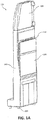
- contoured stowable seat 100 may comprise a housing 102, a plurality of feet 104, a headrest 106, a seat pan 108, and a contoured backrest 110.
- contoured stowable seat 100 is depicted in a stowed position with contoured backrest 110 and seat pan 108 partially stored within housing 102.
- Housing 102 may provide structural support to contoured stowable seat 100.
- Housing 102 may comprise any suitable type of material capable of providing structural support, such as, for example, machined aluminum. Housing 102 may also be reinforced to provide additional structural support, such as, for example, through the use of aluminum side spars.
- Feet 104 may be coupled to the bottom of housing 102, and may protrude downward from housing 102. Feet 104 may also provide a mounting point to mount contoured stowable seat 100 to a surface, such as, for example, an aircraft floor.
- seat pan 108 may be pivotably coupled to housing 102 such that seat pan 108 may pivot in a direction towards housing 102 in a stowed position, and in a direction away from housing 102 in a deployed position.
- seat pan 108 may pivot into a position proximate contoured backrest 110 while in the stowed position.
- Contoured stowable seat 100 in the stowed position may occupy less space than contoured stowable seat 100 in the deployed position.
- Contoured stowable seat 100 may be stowed to conserve useable volume in an aircraft or other application where space may be limited.
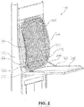
- contoured stowable seat 100 is depicted in the deployed position.
- seat pan 108 may be configured to pivot in a direction away from housing 102 to a deployed position substantially perpendicular with housing 102.
- Seat pan 108 may comprise any suitable type of seat.
- seat pan 108 may comprise a bench seat, a bucket seat, a cushioned seat, and/or any other suitable type of seat.
- headrest 106 may be coupled to the top of housing 102 in a location proximate contoured backrest 110, and may protrude in a direction upward from housing 102. Headrest 106 may be configured to provide support to the head of a passenger sitting on contoured stowable seat 100 while in the deployed position. Headrest 106 may comprise any suitable type of head rest. For example, headrest 106 may comprise a substantially flat surface. Headrest 106 may also comprise a cushioned material. In various embodiments, headrest 106 may also be adjustable, allowing for movement away from, and back towards, housing 102.
- a seat restraint 190 may be configured to secure a passenger sitting in contoured stowable seat 100.
- Seat restraint 190 may comprise any suitable type of seat belt or restraint system and/or mechanism.
- Seat restraint 190 may be coupled at a first end to housing 102 at a position above contoured backrest 110, and at a second end to housing 102 at a position below contoured backrest 110, such as, at the position seat pan 108 pivotably couples to housing 102.
- Seat restraint 190 may also be coupled at the second end to seat pan 108.
- contoured backrest 110 may couple to housing 102 at a first position proximate to headrest 106, and at a second position proximate to seat pan 108.
- Contoured backrest 110 may couple to housing 102 using any suitable technique, such as, for example, through a pivot joint.
- Contoured backrest 110 may also couple to housing 102 at the first position through a slidable joint.
- the slidable joint may enable contoured backrest 110 to move towards the headrest 106 when in the stowed positon, and slide towards feet 104 when in the deployed position.
- contoured backrest 110 may slide down when contoured backrest 110 is in a stretched, contoured position (the deployed position), and slide back when contoured backrest 110 is in a relaxed position (the stowed position).
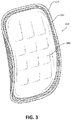
- contoured backrest 110 is depicted in greater detail.
- Contoured backrest 110 may comprise a frame 114 and a stretch backrest 112.
- Frame 114 may be configured to provide structural support to contoured backrest 110.
- Frame 114 may comprise a full hoop design, defining the entire outer edges of contoured backrest 110.
- Frame 114 may also comprise a partial design, such as two parallel frames, defining only the outer sides of contoured backrest 110.
- Frame 114 may comprise any suitable material capable of providing structural support.
- frame 114 may comprise aluminum, carbon fiber, and/or an injection molded plastic.
- frame 114 may comprise a flex point 116.
- Flex point 116 may comprise a portion of frame 114 that has been weakened to allow frame 114 to bend in a direction away from housing 102, such as when contoured stowable seat 100 is in the deployed position.
- Flex point 116 may comprise a portion of frame 114 that is weakened to allow the partial bending of frame 114, but not weakened to the point that frame 114 may easily break while bending.
- flex point 116 may comprise a portion of frame 114 that has been weakened by deformation, thinning of material, notching of the surface, and/or through any other suitable technique.
- stretch backrest 112 may be coupled to frame 114.
- Stretch backrest 112 may couple to frame 114 using any suitable technique.
- stretch backrest 112 may be coupled to frame using a fastener, adhesive, and/or the like.
- frame 114 may comprise an interior channel configured to receive stretch backrest 112.
- stretch backrest 112 may be inserted and crimped within the interior channel of frame 114, coupling stretch backrest 112 to frame 114.
- Stretch backrest 112 may comprise any suitable material.
- stretch backrest 112 may comprise a flame retardant mesh material.
- Stretch backrest 112 may also comprise a nylon mesh material, a two-way stretch material, and/or any other suitable material.
- stretch backrest 112 may comprise an elastomeric fiber material such as Lycra®, Spandex, and/or Elastane.
- contoured stowable seat 100 may also comprise a deployment lever 120 configured to deploy contoured backrest 110 into a contoured shape when seat pan 108 is in a deployed position.
- Deployment lever 120 may be coupled to housing 102 at a proximate position below contoured backrest 110.
- Deployment lever 120 may be coupled to housing 102 using a pivot joint, or other such similar mechanism allowing rotational movement of deployment lever 120 while coupled to housing 102.
- Deployment lever 120 may comprise any suitable shape and size capable of deploying contoured backrest 110 into a contoured shape.
- deployment lever 120 may comprise a wishbone shape, or any other suitable shape having an angle.
- deployment lever 120 may comprise a first deployment end 122 and a second deployment end 124.
- First deployment end 122 may be coupled to seat pan 108.
- first deployment end 122 may be coupled to seat pan 108 such that first deployment end 122 may rotatably move with seat pan 108 when contoured stowable seat 100 is in the deployed and/or the stowed position.
- Second deployment end 124 may be configured as a mechanism to deploy contoured backrest 110 into a contoured shape. In this regard, second deployment end 124 may be located in close proximity to frame 114.
- second deployment end 124 may be pushed into contact against frame 114, forming contoured backrest 110 into a contoured shape.
- contact from second deployment end 124 against frame 114 may also cause flex point 116 to bend in a direction away from housing 102, creating further contour on contoured backrest 110.
- second deployment end 124 may be moved away from frame 114 (towards housing 102) such that contoured backrest 110 may form into a relaxed shape.
- a contoured backrest 310 may also be configured to comprise a contoured pad 380.
- Contoured pad 380 may be coupled to the outer surface of contoured backrest 310.
- contoured pad 380 may be coupled to the outer surface of stretch backrest 112, in a position away from housing 102.
- Contoured pad 380 may be coupled to the outer surface of stretch backrest 112 using any suitable technique.
- contoured pad 380 may be coupled to the outer surface of stretch backrest 112 using an adhesive, through stitching, and/or through any other suitable method.
- Contoured pad 380 may comprise any suitable material and/or coating.
- contoured pad 380 may comprise a foam cushion.
- Contoured pad 380 may also be covered with any desired material, such as cloth, leather, and/or the like.
- a contoured stowable seat 400 may further comprise a tension cord 430.
- Tension cord 430 may comprise a first tension end 432 and a second tension end 434.
- First tension end 432 may be configured to couple to housing 102, using any suitable technique known in the art, such as via a pivot joint.
- First tension end 432 may couple to any desirable location on housing 102.
- Second tension end 434 may be configured to couple to contoured backrest 110 at any desired location, using any suitable technique known in the art.
- Second tension end 434 may couple to any desirable location on contoured backrest 110.
- Tension cord 430 may comprise any suitable material capable of imparting tension in response to contoured stowable seat 400 being in a deployed position.
- tension cord 430 may comprise a pulley cord and/or other similar material having elastic properties.
- tension cord 430 may be configured to reinforce and provide additional contour to contoured backrest 110.
- tension cord 430 in response to contoured stowable seat 400 being in a deployed position, tension cord 430 may impart tension in the proximate area where second tension end 434 is coupled to contoured backrest 110, pulling that proximate area of contoured backrest 110 towards housing 102.
- tension cord 430 may release the tension and enable contoured backrest 110 to return to a slack form.
- Tension cord 430 may therefore provide further contour to contoured backrest 110 by imparting tension to desired areas of contoured backrest 110.
- tension cord 430 may be used to provide greater lumbar support by forming additional contour in the lumbar region of contoured backrest 110.
- Tension cord 430 may also be used to provide more side bolstering to contoured backrest 110, or less predominance to contoured backrest 110.
- Tension cord 430 may also be used in the upper thoracic area to provide relief for shoulder blade support, or may be used in the lower center of contoured backrest 110 to provide relief for tailbone support.
Landscapes
- Engineering & Computer Science (AREA)
- Aviation & Aerospace Engineering (AREA)
- Seats For Vehicles (AREA)
Claims (10)
- Siège escamotable (100 ; 400), comprenant :un boîtier (102) ayant une partie supérieure et une partie inférieure ;une assise de siège (108) couplée de manière pivotante au boîtier (102) à une position entre la partie supérieure et la partie inférieure, dans lequel l'assise de siège (108) est configurée pour pivoter d'une position escamotée à une position déployée ; et un levier de déploiement (120) ayant une première extrémité de déploiement (122) et une deuxième extrémité de déploiement (124) ; caractérisé en ce que le siège escamotable (100 ; 400) est profilé et comprend en outre :un dossier profilé (110 ; 310) comprenant un châssis (114) et un matériau extensible (112), dans lequel le matériau extensible (112) est couplé au châssis (114) et le châssis (114) définit un bord axialement extérieur du matériau extensible (112), et dans lequel le châssis (114) est couplé au boîtier (102) à une première position proche de la partie supérieure du boîtier (102) et à une deuxième position proche de l'endroit où l'assise de siège (108) se couple au boîtier (102) ;dans lequel la première extrémité de déploiement (122) du levier (120) est couplée à l'assise de siège (108) à un endroit proche du couplage de l'assise de siège (108) au boîtier (102), et dans lequel la deuxième extrémité de déploiement (124) est configurée pour entrer en contact avec le châssis (114) du dossier profilé (110 ; 310) en réponse au fait que l'assise de siège (108) est dans la position déployée, amenant le dossier profilé (110 ; 310) à se déployer dans une forme profilée.
- Siège escamotable selon la revendication 1, comprenant en outre un cordon de tension (430) ayant une première extrémité (432) et une deuxième extrémité (434), dans lequel la première extrémité (432) est couplée au boîtier (102) et la deuxième extrémité (434) est couplée au matériau extensible (112) du dossier profilé (110 ; 310).
- Siège escamotable selon la revendication 2, dans lequel en réponse à l'assise de siège (108) pivotant dans la position déployée, le cordon de tenson (430) est configuré pour déployer le dossier profilé (110 ; 310) dans une deuxième forme profilée par application de tension à un endroit où la deuxième extrémité (434) est couplée au dossier profilé (110 ; 310) .
- Siège escamotable profilé selon l'une quelconque des revendications 1 à 3, dans lequel l'assise de siège (108) et le dossier profilé (110 ; 310) sont configurés pour s'escamoter au moins partiellement dans le boîtier (102) en réponse au fait que l'assise de siège (108) est dans la position escamotée.
- Siège escamotable profilé selon une quelconque revendication précédente, comprenant en outre un coussin profilé (380) couplé à une surface axialement extérieure du matériau extensible (112) du dossier profilé (310).
- Siège escamotable profilé selon une quelconque revendication précédente, dans lequel le châssis (114) du dossier profilé (110 ; 310) est couplé au boîtier (102) à la première position via une articulation coulissante, permettant au dossier profilé (110 ; 310) de coulisser par rapport au boîtier (102) en réponse au fait que l'assise de siège (108) pivote dans la position déployée.
- Siège escamotable profilé selon une quelconque revendication précédente, comprenant en outre un appui-tête (106) couplé à la partie supérieure du boîtier (102).
- Siège escamotable profilé selon une quelconque revendication précédente, comprenant en outre un dispositif de retenue de siège (190) couplé au boîtier (102).
- Siège escamotable profilé selon une quelconque revendication précédente, dans lequel le châssis (114) comprend un point de flexion (116) configuré pour se plier dans une direction s'éloignant du boîtier (102), en réponse au fait que l'assise de siège (108) pivote dans la position déployée.
- Procédé de fonctionnement du siège selon une quelconque revendication précédente, comprenant :le pivotement de l'assise de siège (108) dans la position déployée, dans lequel en réponse au fait que l'assise de siège (108) est dans la position déployée, le levier de déploiement (120) est configuré pour déployer le dossier profilé (110 ;310) dans la forme profilée ; etle pivotement de l'assise de siège (108) dans la position escamotée, dans lequel en réponse au fait que l'assise de siège (108) est dans la position escamotée, le levier de déploiement (120) est configuré pour permettre au dossier profilé (110 ; 310) de se former dans une forme relâchée.
Priority Applications (1)
| Application Number | Priority Date | Filing Date | Title |
|---|---|---|---|
| EP18199905.3A EP3446978B1 (fr) | 2016-03-29 | 2017-03-29 | Siège escamotable profilé |
Applications Claiming Priority (1)
| Application Number | Priority Date | Filing Date | Title |
|---|---|---|---|
| US15/083,532 US9873510B2 (en) | 2016-03-29 | 2016-03-29 | Contoured stowable seat |
Related Child Applications (2)
| Application Number | Title | Priority Date | Filing Date |
|---|---|---|---|
| EP18199905.3A Division EP3446978B1 (fr) | 2016-03-29 | 2017-03-29 | Siège escamotable profilé |
| EP18199905.3A Division-Into EP3446978B1 (fr) | 2016-03-29 | 2017-03-29 | Siège escamotable profilé |
Publications (2)
| Publication Number | Publication Date |
|---|---|
| EP3225552A1 EP3225552A1 (fr) | 2017-10-04 |
| EP3225552B1 true EP3225552B1 (fr) | 2018-12-12 |
Family
ID=58454960
Family Applications (2)
| Application Number | Title | Priority Date | Filing Date |
|---|---|---|---|
| EP17163593.1A Not-in-force EP3225552B1 (fr) | 2016-03-29 | 2017-03-29 | Siège escamotable profilé |
| EP18199905.3A Not-in-force EP3446978B1 (fr) | 2016-03-29 | 2017-03-29 | Siège escamotable profilé |
Family Applications After (1)
| Application Number | Title | Priority Date | Filing Date |
|---|---|---|---|
| EP18199905.3A Not-in-force EP3446978B1 (fr) | 2016-03-29 | 2017-03-29 | Siège escamotable profilé |
Country Status (5)
| Country | Link |
|---|---|
| US (1) | US9873510B2 (fr) |
| EP (2) | EP3225552B1 (fr) |
| CN (1) | CN107235151B (fr) |
| BR (2) | BR122021017571B1 (fr) |
| CA (1) | CA2956759A1 (fr) |
Families Citing this family (7)
| Publication number | Priority date | Publication date | Assignee | Title |
|---|---|---|---|---|
| US10273008B2 (en) | 2017-03-24 | 2019-04-30 | Ami Industries, Inc. | Inertia reel interface for stowable seats |
| WO2019229511A1 (fr) * | 2018-05-30 | 2019-12-05 | Safran Seats Usa Llc | Ensemble siège ayant une inclinaison de fond de siège indépendante |
| CN108835984B (zh) * | 2018-06-27 | 2021-08-24 | 新沂新昆金属制品有限公司 | 一种柚木折叠凳 |
| EP3922560B1 (fr) * | 2020-06-13 | 2024-11-20 | AMI Industries, Inc. | Cadre d'étanchéité réglable pour sièges de membre d'équipage montés au sol |
| US11787546B2 (en) * | 2020-06-13 | 2023-10-17 | Ami Industries, Inc. | Adjustable seal frame for floor mounted cabin attendant seats |
| CN113895633B (zh) * | 2021-12-10 | 2022-02-18 | 大同航源众诚动力科技有限公司 | 一种民用航空器安全带装置 |
| US12371168B1 (en) | 2024-01-15 | 2025-07-29 | B/E Aerospace, Inc. | Seat bottom assembly with self tensioning diaphragm and under seat access |
Family Cites Families (9)
| Publication number | Priority date | Publication date | Assignee | Title |
|---|---|---|---|---|
| US4460215A (en) * | 1981-09-30 | 1984-07-17 | The Boeing Company | Folding seat assembly |
| US4437629A (en) | 1982-08-09 | 1984-03-20 | The Boeing Company | Seat structure having an adjustable seat back and support shelf especially for accommodating parachute packs |
| DE8623246U1 (de) * | 1986-08-29 | 1988-01-14 | Baymak, Faruk, Dipl.-Ing., 2000 Hamburg | Sitzeinheit für einen Begleiter in einem Fahrzeug, insbesondere in einem Luftfahrzeug |
| DE3822574A1 (de) * | 1988-07-04 | 1990-01-11 | Messerschmitt Boelkow Blohm | Sitz, insbesondere fuer einen flugbegleiter |
| US20070132296A1 (en) * | 2005-12-14 | 2007-06-14 | Lear Corporation | Automatic lumbar support system for a folding seat system |
| US7841663B2 (en) | 2008-10-01 | 2010-11-30 | Lear Corporation | Vehicle seat lumbar system |
| US8528182B2 (en) * | 2009-02-23 | 2013-09-10 | L & P Property Management Company | Achieving tension in a seating unit by pre-forming a frame |
| DE102011104972B4 (de) * | 2011-06-08 | 2015-03-05 | Haworth, Inc. | Sitzmöbel, insbesondere Bürostuhl |
| US9180793B2 (en) | 2011-12-20 | 2015-11-10 | Franklin Products, Inc. | Movable seating arrangement |
-
2016
- 2016-03-29 US US15/083,532 patent/US9873510B2/en not_active Expired - Fee Related
-
2017
- 2017-01-30 CA CA2956759A patent/CA2956759A1/fr active Pending
- 2017-03-13 BR BR122021017571-3A patent/BR122021017571B1/pt active IP Right Grant
- 2017-03-13 BR BR102017004937A patent/BR102017004937B8/pt not_active IP Right Cessation
- 2017-03-29 EP EP17163593.1A patent/EP3225552B1/fr not_active Not-in-force
- 2017-03-29 EP EP18199905.3A patent/EP3446978B1/fr not_active Not-in-force
- 2017-03-29 CN CN201710197045.6A patent/CN107235151B/zh not_active Expired - Fee Related
Non-Patent Citations (1)
| Title |
|---|
| None * |
Also Published As
| Publication number | Publication date |
|---|---|
| BR102017004937A2 (pt) | 2017-10-03 |
| BR102017004937B8 (pt) | 2022-10-11 |
| CN107235151B (zh) | 2021-03-09 |
| EP3446978B1 (fr) | 2020-04-29 |
| BR102017004937B1 (pt) | 2022-07-19 |
| BR122021017571B1 (pt) | 2022-07-19 |
| US9873510B2 (en) | 2018-01-23 |
| US20170283072A1 (en) | 2017-10-05 |
| CA2956759A1 (fr) | 2017-09-29 |
| EP3225552A1 (fr) | 2017-10-04 |
| CN107235151A (zh) | 2017-10-10 |
| EP3446978A1 (fr) | 2019-02-27 |
Similar Documents
| Publication | Publication Date | Title |
|---|---|---|
| EP3225552B1 (fr) | Siège escamotable profilé | |
| EP3010376B1 (fr) | Siège compact d'équipage de cabine | |
| US8939507B2 (en) | Backrest for a vehicle seat | |
| US10414503B2 (en) | Components for enhancement of a low profile crew attendant seat | |
| US11760490B2 (en) | Device for closing a space within an airplane | |
| US12030641B2 (en) | Seat arrangement, in particular for an airplane | |
| EP2726373B1 (fr) | Plateau à usages multiples | |
| US8376466B2 (en) | Aircraft seat | |
| EP3227183B1 (fr) | Tablette | |
| US10773626B2 (en) | Adjustable headrest enabling sideward leaning and seclusion | |
| EP3225459B1 (fr) | Dossier de siège pour véhicule | |
| US10543923B2 (en) | Seat backrest | |
| WO2016128524A1 (fr) | Ensemble siège passager d'aéronef léger | |
| US11319075B1 (en) | Compressible cushion for an aircraft seat | |
| EP3569503A1 (fr) | Fauteuil de salon pour aéronef | |
| WO2008048908A2 (fr) | Siège pour aéronef | |
| EP3362358B1 (fr) | Siège passager comprenant un dossier net | |
| US20160001886A1 (en) | Aircraft seat cover and aircraft divan equipped with same | |
| WO2016030843A1 (fr) | Siège compact en tissu élastique | |
| US10821863B1 (en) | Retention member for vehicle seating assembly | |
| CA2855449A1 (fr) | Revetement de siege d'aeronef et divan d'aeronef equipe dudit revetement | |
| EP4480822A1 (fr) | Conversion de siège économique en lit entièrement plat par chute de cadre de dossier de siège | |
| US20240017833A1 (en) | Vehicle seat | |
| WO2015155688A1 (fr) | Siège léger |
Legal Events
| Date | Code | Title | Description |
|---|---|---|---|
| PUAI | Public reference made under article 153(3) epc to a published international application that has entered the european phase |
Free format text: ORIGINAL CODE: 0009012 |
|
| STAA | Information on the status of an ep patent application or granted ep patent |
Free format text: STATUS: THE APPLICATION HAS BEEN PUBLISHED |
|
| AK | Designated contracting states |
Kind code of ref document: A1 Designated state(s): AL AT BE BG CH CY CZ DE DK EE ES FI FR GB GR HR HU IE IS IT LI LT LU LV MC MK MT NL NO PL PT RO RS SE SI SK SM TR |
|
| AX | Request for extension of the european patent |
Extension state: BA ME |
|
| STAA | Information on the status of an ep patent application or granted ep patent |
Free format text: STATUS: REQUEST FOR EXAMINATION WAS MADE |
|
| 17P | Request for examination filed |
Effective date: 20180404 |
|
| RBV | Designated contracting states (corrected) |
Designated state(s): AL AT BE BG CH CY CZ DE DK EE ES FI FR GB GR HR HU IE IS IT LI LT LU LV MC MK MT NL NO PL PT RO RS SE SI SK SM TR |
|
| GRAP | Despatch of communication of intention to grant a patent |
Free format text: ORIGINAL CODE: EPIDOSNIGR1 |
|
| STAA | Information on the status of an ep patent application or granted ep patent |
Free format text: STATUS: GRANT OF PATENT IS INTENDED |
|
| INTG | Intention to grant announced |
Effective date: 20180615 |
|
| GRAS | Grant fee paid |
Free format text: ORIGINAL CODE: EPIDOSNIGR3 |
|
| GRAA | (expected) grant |
Free format text: ORIGINAL CODE: 0009210 |
|
| STAA | Information on the status of an ep patent application or granted ep patent |
Free format text: STATUS: THE PATENT HAS BEEN GRANTED |
|
| AK | Designated contracting states |
Kind code of ref document: B1 Designated state(s): AL AT BE BG CH CY CZ DE DK EE ES FI FR GB GR HR HU IE IS IT LI LT LU LV MC MK MT NL NO PL PT RO RS SE SI SK SM TR |
|
| REG | Reference to a national code |
Ref country code: GB Ref legal event code: FG4D |
|
| REG | Reference to a national code |
Ref country code: CH Ref legal event code: EP |
|
| REG | Reference to a national code |
Ref country code: AT Ref legal event code: REF Ref document number: 1075644 Country of ref document: AT Kind code of ref document: T Effective date: 20181215 |
|
| REG | Reference to a national code |
Ref country code: DE Ref legal event code: R096 Ref document number: 602017001282 Country of ref document: DE |
|
| REG | Reference to a national code |
Ref country code: IE Ref legal event code: FG4D |
|
| REG | Reference to a national code |
Ref country code: NL Ref legal event code: MP Effective date: 20181212 |
|
| REG | Reference to a national code |
Ref country code: LT Ref legal event code: MG4D |
|
| PG25 | Lapsed in a contracting state [announced via postgrant information from national office to epo] |
Ref country code: LV Free format text: LAPSE BECAUSE OF FAILURE TO SUBMIT A TRANSLATION OF THE DESCRIPTION OR TO PAY THE FEE WITHIN THE PRESCRIBED TIME-LIMIT Effective date: 20181212 Ref country code: NO Free format text: LAPSE BECAUSE OF FAILURE TO SUBMIT A TRANSLATION OF THE DESCRIPTION OR TO PAY THE FEE WITHIN THE PRESCRIBED TIME-LIMIT Effective date: 20190312 Ref country code: LT Free format text: LAPSE BECAUSE OF FAILURE TO SUBMIT A TRANSLATION OF THE DESCRIPTION OR TO PAY THE FEE WITHIN THE PRESCRIBED TIME-LIMIT Effective date: 20181212 Ref country code: FI Free format text: LAPSE BECAUSE OF FAILURE TO SUBMIT A TRANSLATION OF THE DESCRIPTION OR TO PAY THE FEE WITHIN THE PRESCRIBED TIME-LIMIT Effective date: 20181212 Ref country code: BG Free format text: LAPSE BECAUSE OF FAILURE TO SUBMIT A TRANSLATION OF THE DESCRIPTION OR TO PAY THE FEE WITHIN THE PRESCRIBED TIME-LIMIT Effective date: 20190312 Ref country code: HR Free format text: LAPSE BECAUSE OF FAILURE TO SUBMIT A TRANSLATION OF THE DESCRIPTION OR TO PAY THE FEE WITHIN THE PRESCRIBED TIME-LIMIT Effective date: 20181212 |
|
| REG | Reference to a national code |
Ref country code: AT Ref legal event code: MK05 Ref document number: 1075644 Country of ref document: AT Kind code of ref document: T Effective date: 20181212 |
|
| PG25 | Lapsed in a contracting state [announced via postgrant information from national office to epo] |
Ref country code: RS Free format text: LAPSE BECAUSE OF FAILURE TO SUBMIT A TRANSLATION OF THE DESCRIPTION OR TO PAY THE FEE WITHIN THE PRESCRIBED TIME-LIMIT Effective date: 20181212 Ref country code: GR Free format text: LAPSE BECAUSE OF FAILURE TO SUBMIT A TRANSLATION OF THE DESCRIPTION OR TO PAY THE FEE WITHIN THE PRESCRIBED TIME-LIMIT Effective date: 20190313 Ref country code: AL Free format text: LAPSE BECAUSE OF FAILURE TO SUBMIT A TRANSLATION OF THE DESCRIPTION OR TO PAY THE FEE WITHIN THE PRESCRIBED TIME-LIMIT Effective date: 20181212 Ref country code: SE Free format text: LAPSE BECAUSE OF FAILURE TO SUBMIT A TRANSLATION OF THE DESCRIPTION OR TO PAY THE FEE WITHIN THE PRESCRIBED TIME-LIMIT Effective date: 20181212 |
|
| PG25 | Lapsed in a contracting state [announced via postgrant information from national office to epo] |
Ref country code: NL Free format text: LAPSE BECAUSE OF FAILURE TO SUBMIT A TRANSLATION OF THE DESCRIPTION OR TO PAY THE FEE WITHIN THE PRESCRIBED TIME-LIMIT Effective date: 20181212 |
|
| PG25 | Lapsed in a contracting state [announced via postgrant information from national office to epo] |
Ref country code: ES Free format text: LAPSE BECAUSE OF FAILURE TO SUBMIT A TRANSLATION OF THE DESCRIPTION OR TO PAY THE FEE WITHIN THE PRESCRIBED TIME-LIMIT Effective date: 20181212 Ref country code: IT Free format text: LAPSE BECAUSE OF FAILURE TO SUBMIT A TRANSLATION OF THE DESCRIPTION OR TO PAY THE FEE WITHIN THE PRESCRIBED TIME-LIMIT Effective date: 20181212 Ref country code: PL Free format text: LAPSE BECAUSE OF FAILURE TO SUBMIT A TRANSLATION OF THE DESCRIPTION OR TO PAY THE FEE WITHIN THE PRESCRIBED TIME-LIMIT Effective date: 20181212 Ref country code: PT Free format text: LAPSE BECAUSE OF FAILURE TO SUBMIT A TRANSLATION OF THE DESCRIPTION OR TO PAY THE FEE WITHIN THE PRESCRIBED TIME-LIMIT Effective date: 20190412 Ref country code: CZ Free format text: LAPSE BECAUSE OF FAILURE TO SUBMIT A TRANSLATION OF THE DESCRIPTION OR TO PAY THE FEE WITHIN THE PRESCRIBED TIME-LIMIT Effective date: 20181212 |
|
| PG25 | Lapsed in a contracting state [announced via postgrant information from national office to epo] |
Ref country code: SK Free format text: LAPSE BECAUSE OF FAILURE TO SUBMIT A TRANSLATION OF THE DESCRIPTION OR TO PAY THE FEE WITHIN THE PRESCRIBED TIME-LIMIT Effective date: 20181212 Ref country code: IS Free format text: LAPSE BECAUSE OF FAILURE TO SUBMIT A TRANSLATION OF THE DESCRIPTION OR TO PAY THE FEE WITHIN THE PRESCRIBED TIME-LIMIT Effective date: 20190412 Ref country code: RO Free format text: LAPSE BECAUSE OF FAILURE TO SUBMIT A TRANSLATION OF THE DESCRIPTION OR TO PAY THE FEE WITHIN THE PRESCRIBED TIME-LIMIT Effective date: 20181212 Ref country code: SM Free format text: LAPSE BECAUSE OF FAILURE TO SUBMIT A TRANSLATION OF THE DESCRIPTION OR TO PAY THE FEE WITHIN THE PRESCRIBED TIME-LIMIT Effective date: 20181212 Ref country code: EE Free format text: LAPSE BECAUSE OF FAILURE TO SUBMIT A TRANSLATION OF THE DESCRIPTION OR TO PAY THE FEE WITHIN THE PRESCRIBED TIME-LIMIT Effective date: 20181212 |
|
| REG | Reference to a national code |
Ref country code: DE Ref legal event code: R097 Ref document number: 602017001282 Country of ref document: DE |
|
| PLBE | No opposition filed within time limit |
Free format text: ORIGINAL CODE: 0009261 |
|
| STAA | Information on the status of an ep patent application or granted ep patent |
Free format text: STATUS: NO OPPOSITION FILED WITHIN TIME LIMIT |
|
| PG25 | Lapsed in a contracting state [announced via postgrant information from national office to epo] |
Ref country code: SI Free format text: LAPSE BECAUSE OF FAILURE TO SUBMIT A TRANSLATION OF THE DESCRIPTION OR TO PAY THE FEE WITHIN THE PRESCRIBED TIME-LIMIT Effective date: 20181212 Ref country code: AT Free format text: LAPSE BECAUSE OF FAILURE TO SUBMIT A TRANSLATION OF THE DESCRIPTION OR TO PAY THE FEE WITHIN THE PRESCRIBED TIME-LIMIT Effective date: 20181212 Ref country code: DK Free format text: LAPSE BECAUSE OF FAILURE TO SUBMIT A TRANSLATION OF THE DESCRIPTION OR TO PAY THE FEE WITHIN THE PRESCRIBED TIME-LIMIT Effective date: 20181212 Ref country code: MC Free format text: LAPSE BECAUSE OF FAILURE TO SUBMIT A TRANSLATION OF THE DESCRIPTION OR TO PAY THE FEE WITHIN THE PRESCRIBED TIME-LIMIT Effective date: 20181212 |
|
| 26N | No opposition filed |
Effective date: 20190913 |
|
| PG25 | Lapsed in a contracting state [announced via postgrant information from national office to epo] |
Ref country code: LU Free format text: LAPSE BECAUSE OF NON-PAYMENT OF DUE FEES Effective date: 20190329 |
|
| REG | Reference to a national code |
Ref country code: BE Ref legal event code: MM Effective date: 20190331 |
|
| PG25 | Lapsed in a contracting state [announced via postgrant information from national office to epo] |
Ref country code: IE Free format text: LAPSE BECAUSE OF NON-PAYMENT OF DUE FEES Effective date: 20190329 |
|
| PG25 | Lapsed in a contracting state [announced via postgrant information from national office to epo] |
Ref country code: BE Free format text: LAPSE BECAUSE OF NON-PAYMENT OF DUE FEES Effective date: 20190331 |
|
| PG25 | Lapsed in a contracting state [announced via postgrant information from national office to epo] |
Ref country code: TR Free format text: LAPSE BECAUSE OF FAILURE TO SUBMIT A TRANSLATION OF THE DESCRIPTION OR TO PAY THE FEE WITHIN THE PRESCRIBED TIME-LIMIT Effective date: 20181212 |
|
| PG25 | Lapsed in a contracting state [announced via postgrant information from national office to epo] |
Ref country code: MT Free format text: LAPSE BECAUSE OF NON-PAYMENT OF DUE FEES Effective date: 20190329 |
|
| REG | Reference to a national code |
Ref country code: CH Ref legal event code: PL |
|
| PG25 | Lapsed in a contracting state [announced via postgrant information from national office to epo] |
Ref country code: LI Free format text: LAPSE BECAUSE OF NON-PAYMENT OF DUE FEES Effective date: 20200331 Ref country code: CH Free format text: LAPSE BECAUSE OF NON-PAYMENT OF DUE FEES Effective date: 20200331 |
|
| PG25 | Lapsed in a contracting state [announced via postgrant information from national office to epo] |
Ref country code: CY Free format text: LAPSE BECAUSE OF FAILURE TO SUBMIT A TRANSLATION OF THE DESCRIPTION OR TO PAY THE FEE WITHIN THE PRESCRIBED TIME-LIMIT Effective date: 20181212 |
|
| PG25 | Lapsed in a contracting state [announced via postgrant information from national office to epo] |
Ref country code: HU Free format text: LAPSE BECAUSE OF FAILURE TO SUBMIT A TRANSLATION OF THE DESCRIPTION OR TO PAY THE FEE WITHIN THE PRESCRIBED TIME-LIMIT; INVALID AB INITIO Effective date: 20170329 |
|
| PG25 | Lapsed in a contracting state [announced via postgrant information from national office to epo] |
Ref country code: MK Free format text: LAPSE BECAUSE OF FAILURE TO SUBMIT A TRANSLATION OF THE DESCRIPTION OR TO PAY THE FEE WITHIN THE PRESCRIBED TIME-LIMIT Effective date: 20181212 |
|
| P01 | Opt-out of the competence of the unified patent court (upc) registered |
Effective date: 20230521 |
|
| PGFP | Annual fee paid to national office [announced via postgrant information from national office to epo] |
Ref country code: DE Payment date: 20240220 Year of fee payment: 8 Ref country code: GB Payment date: 20240220 Year of fee payment: 8 |
|
| PGFP | Annual fee paid to national office [announced via postgrant information from national office to epo] |
Ref country code: FR Payment date: 20240220 Year of fee payment: 8 |
|
| REG | Reference to a national code |
Ref country code: DE Ref legal event code: R119 Ref document number: 602017001282 Country of ref document: DE |
|
| GBPC | Gb: european patent ceased through non-payment of renewal fee |
Effective date: 20250329 |
|
| PG25 | Lapsed in a contracting state [announced via postgrant information from national office to epo] |
Ref country code: DE Free format text: LAPSE BECAUSE OF NON-PAYMENT OF DUE FEES Effective date: 20251001 |
|
| PG25 | Lapsed in a contracting state [announced via postgrant information from national office to epo] |
Ref country code: GB Free format text: LAPSE BECAUSE OF NON-PAYMENT OF DUE FEES Effective date: 20250329 |
|
| PG25 | Lapsed in a contracting state [announced via postgrant information from national office to epo] |
Ref country code: FR Free format text: LAPSE BECAUSE OF NON-PAYMENT OF DUE FEES Effective date: 20250331 |