EP3225542B1 - A method of manufacturing a control cuff for a rotor blade of a hinge- and bearingless rotor - Google Patents
A method of manufacturing a control cuff for a rotor blade of a hinge- and bearingless rotor Download PDFInfo
- Publication number
- EP3225542B1 EP3225542B1 EP16400007.7A EP16400007A EP3225542B1 EP 3225542 B1 EP3225542 B1 EP 3225542B1 EP 16400007 A EP16400007 A EP 16400007A EP 3225542 B1 EP3225542 B1 EP 3225542B1
- Authority
- EP
- European Patent Office
- Prior art keywords
- stiffener member
- manufacturing
- outer shell
- rotor
- stiffener
- Prior art date
- Legal status (The legal status is an assumption and is not a legal conclusion. Google has not performed a legal analysis and makes no representation as to the accuracy of the status listed.)
- Active
Links
Images

Classifications
-
- B—PERFORMING OPERATIONS; TRANSPORTING
- B64—AIRCRAFT; AVIATION; COSMONAUTICS
- B64C—AEROPLANES; HELICOPTERS
- B64C27/00—Rotorcraft; Rotors peculiar thereto
- B64C27/54—Mechanisms for controlling blade adjustment or movement relative to rotor head, e.g. lag-lead movement
- B64C27/58—Transmitting means, e.g. interrelated with initiating means or means acting on blades
- B64C27/59—Transmitting means, e.g. interrelated with initiating means or means acting on blades mechanical
- B64C27/635—Transmitting means, e.g. interrelated with initiating means or means acting on blades mechanical specially for controlling lag-lead movements of blades
-
- B—PERFORMING OPERATIONS; TRANSPORTING
- B64—AIRCRAFT; AVIATION; COSMONAUTICS
- B64C—AEROPLANES; HELICOPTERS
- B64C27/00—Rotorcraft; Rotors peculiar thereto
- B64C27/32—Rotors
- B64C27/33—Rotors having flexing arms
-
- B—PERFORMING OPERATIONS; TRANSPORTING
- B22—CASTING; POWDER METALLURGY
- B22F—WORKING METALLIC POWDER; MANUFACTURE OF ARTICLES FROM METALLIC POWDER; MAKING METALLIC POWDER; APPARATUS OR DEVICES SPECIALLY ADAPTED FOR METALLIC POWDER
- B22F5/00—Manufacture of workpieces or articles from metallic powder characterised by the special shape of the product
-
- B—PERFORMING OPERATIONS; TRANSPORTING
- B22—CASTING; POWDER METALLURGY
- B22F—WORKING METALLIC POWDER; MANUFACTURE OF ARTICLES FROM METALLIC POWDER; MAKING METALLIC POWDER; APPARATUS OR DEVICES SPECIALLY ADAPTED FOR METALLIC POWDER
- B22F7/00—Manufacture of composite layers, workpieces, or articles, comprising metallic powder, by sintering the powder, with or without compacting wherein at least one part is obtained by sintering or compression
- B22F7/06—Manufacture of composite layers, workpieces, or articles, comprising metallic powder, by sintering the powder, with or without compacting wherein at least one part is obtained by sintering or compression of composite workpieces or articles from parts, e.g. to form tipped tools
- B22F7/08—Manufacture of composite layers, workpieces, or articles, comprising metallic powder, by sintering the powder, with or without compacting wherein at least one part is obtained by sintering or compression of composite workpieces or articles from parts, e.g. to form tipped tools with one or more parts not made from powder
-
- B—PERFORMING OPERATIONS; TRANSPORTING
- B23—MACHINE TOOLS; METAL-WORKING NOT OTHERWISE PROVIDED FOR
- B23C—MILLING
- B23C3/00—Milling particular work; Special milling operations; Machines therefor
-
- B—PERFORMING OPERATIONS; TRANSPORTING
- B29—WORKING OF PLASTICS; WORKING OF SUBSTANCES IN A PLASTIC STATE IN GENERAL
- B29C—SHAPING OR JOINING OF PLASTICS; SHAPING OF MATERIAL IN A PLASTIC STATE, NOT OTHERWISE PROVIDED FOR; AFTER-TREATMENT OF THE SHAPED PRODUCTS, e.g. REPAIRING
- B29C65/00—Joining or sealing of preformed parts, e.g. welding of plastics materials; Apparatus therefor
- B29C65/48—Joining or sealing of preformed parts, e.g. welding of plastics materials; Apparatus therefor using adhesives, i.e. using supplementary joining material; solvent bonding
- B29C65/52—Joining or sealing of preformed parts, e.g. welding of plastics materials; Apparatus therefor using adhesives, i.e. using supplementary joining material; solvent bonding characterised by the way of applying the adhesive
- B29C65/54—Joining or sealing of preformed parts, e.g. welding of plastics materials; Apparatus therefor using adhesives, i.e. using supplementary joining material; solvent bonding characterised by the way of applying the adhesive between pre-assembled parts
- B29C65/542—Joining or sealing of preformed parts, e.g. welding of plastics materials; Apparatus therefor using adhesives, i.e. using supplementary joining material; solvent bonding characterised by the way of applying the adhesive between pre-assembled parts by injection
-
- B—PERFORMING OPERATIONS; TRANSPORTING
- B29—WORKING OF PLASTICS; WORKING OF SUBSTANCES IN A PLASTIC STATE IN GENERAL
- B29C—SHAPING OR JOINING OF PLASTICS; SHAPING OF MATERIAL IN A PLASTIC STATE, NOT OTHERWISE PROVIDED FOR; AFTER-TREATMENT OF THE SHAPED PRODUCTS, e.g. REPAIRING
- B29C70/00—Shaping composites, i.e. plastics material comprising reinforcements, fillers or preformed parts, e.g. inserts
- B29C70/04—Shaping composites, i.e. plastics material comprising reinforcements, fillers or preformed parts, e.g. inserts comprising reinforcements only, e.g. self-reinforcing plastics
- B29C70/28—Shaping operations therefor
- B29C70/30—Shaping by lay-up, i.e. applying fibres, tape or broadsheet on a mould, former or core; Shaping by spray-up, i.e. spraying of fibres on a mould, former or core
- B29C70/38—Automated lay-up, e.g. using robots, laying filaments according to predetermined patterns
- B29C70/382—Automated fiber placement [AFP]
-
- B—PERFORMING OPERATIONS; TRANSPORTING
- B29—WORKING OF PLASTICS; WORKING OF SUBSTANCES IN A PLASTIC STATE IN GENERAL
- B29D—PRODUCING PARTICULAR ARTICLES FROM PLASTICS OR FROM SUBSTANCES IN A PLASTIC STATE
- B29D99/00—Subject matter not provided for in other groups of this subclass
- B29D99/0025—Producing blades or the like, e.g. blades for turbines, propellers, or wings
-
- B—PERFORMING OPERATIONS; TRANSPORTING
- B32—LAYERED PRODUCTS
- B32B—LAYERED PRODUCTS, i.e. PRODUCTS BUILT-UP OF STRATA OF FLAT OR NON-FLAT, e.g. CELLULAR OR HONEYCOMB, FORM
- B32B37/00—Methods or apparatus for laminating, e.g. by curing or by ultrasonic bonding
- B32B37/0038—Methods or apparatus for laminating, e.g. by curing or by ultrasonic bonding involving application of liquid to the layers prior to lamination, e.g. wet laminating
-
- B—PERFORMING OPERATIONS; TRANSPORTING
- B32—LAYERED PRODUCTS
- B32B—LAYERED PRODUCTS, i.e. PRODUCTS BUILT-UP OF STRATA OF FLAT OR NON-FLAT, e.g. CELLULAR OR HONEYCOMB, FORM
- B32B37/00—Methods or apparatus for laminating, e.g. by curing or by ultrasonic bonding
- B32B37/12—Methods or apparatus for laminating, e.g. by curing or by ultrasonic bonding characterised by using adhesives
- B32B37/1284—Application of adhesive
-
- B—PERFORMING OPERATIONS; TRANSPORTING
- B32—LAYERED PRODUCTS
- B32B—LAYERED PRODUCTS, i.e. PRODUCTS BUILT-UP OF STRATA OF FLAT OR NON-FLAT, e.g. CELLULAR OR HONEYCOMB, FORM
- B32B37/00—Methods or apparatus for laminating, e.g. by curing or by ultrasonic bonding
- B32B37/14—Methods or apparatus for laminating, e.g. by curing or by ultrasonic bonding characterised by the properties of the layers
- B32B37/16—Methods or apparatus for laminating, e.g. by curing or by ultrasonic bonding characterised by the properties of the layers with all layers existing as coherent layers before laminating
-
- B—PERFORMING OPERATIONS; TRANSPORTING
- B32—LAYERED PRODUCTS
- B32B—LAYERED PRODUCTS, i.e. PRODUCTS BUILT-UP OF STRATA OF FLAT OR NON-FLAT, e.g. CELLULAR OR HONEYCOMB, FORM
- B32B37/00—Methods or apparatus for laminating, e.g. by curing or by ultrasonic bonding
- B32B37/14—Methods or apparatus for laminating, e.g. by curing or by ultrasonic bonding characterised by the properties of the layers
- B32B37/24—Methods or apparatus for laminating, e.g. by curing or by ultrasonic bonding characterised by the properties of the layers with at least one layer not being coherent before laminating, e.g. made up from granular material sprinkled onto a substrate
-
- B—PERFORMING OPERATIONS; TRANSPORTING
- B32—LAYERED PRODUCTS
- B32B—LAYERED PRODUCTS, i.e. PRODUCTS BUILT-UP OF STRATA OF FLAT OR NON-FLAT, e.g. CELLULAR OR HONEYCOMB, FORM
- B32B38/00—Ancillary operations in connection with laminating processes
- B32B38/0004—Cutting, tearing or severing, e.g. bursting; Cutter details
-
- B—PERFORMING OPERATIONS; TRANSPORTING
- B64—AIRCRAFT; AVIATION; COSMONAUTICS
- B64C—AEROPLANES; HELICOPTERS
- B64C27/00—Rotorcraft; Rotors peculiar thereto
- B64C27/51—Damping of blade movements
-
- B—PERFORMING OPERATIONS; TRANSPORTING
- B64—AIRCRAFT; AVIATION; COSMONAUTICS
- B64C—AEROPLANES; HELICOPTERS
- B64C27/00—Rotorcraft; Rotors peculiar thereto
- B64C27/54—Mechanisms for controlling blade adjustment or movement relative to rotor head, e.g. lag-lead movement
- B64C27/72—Means acting on blades
-
- B—PERFORMING OPERATIONS; TRANSPORTING
- B23—MACHINE TOOLS; METAL-WORKING NOT OTHERWISE PROVIDED FOR
- B23C—MILLING
- B23C2220/00—Details of milling processes
- B23C2220/48—Methods of milling not otherwise provided for
-
- B—PERFORMING OPERATIONS; TRANSPORTING
- B32—LAYERED PRODUCTS
- B32B—LAYERED PRODUCTS, i.e. PRODUCTS BUILT-UP OF STRATA OF FLAT OR NON-FLAT, e.g. CELLULAR OR HONEYCOMB, FORM
- B32B2305/00—Condition, form or state of the layers or laminate
- B32B2305/07—Parts immersed or impregnated in a matrix
- B32B2305/076—Prepregs
-
- B—PERFORMING OPERATIONS; TRANSPORTING
- B32—LAYERED PRODUCTS
- B32B—LAYERED PRODUCTS, i.e. PRODUCTS BUILT-UP OF STRATA OF FLAT OR NON-FLAT, e.g. CELLULAR OR HONEYCOMB, FORM
- B32B2603/00—Vanes, blades, propellers, rotors with blades
-
- B—PERFORMING OPERATIONS; TRANSPORTING
- B32—LAYERED PRODUCTS
- B32B—LAYERED PRODUCTS, i.e. PRODUCTS BUILT-UP OF STRATA OF FLAT OR NON-FLAT, e.g. CELLULAR OR HONEYCOMB, FORM
- B32B2605/00—Vehicles
- B32B2605/18—Aircraft
-
- B—PERFORMING OPERATIONS; TRANSPORTING
- B33—ADDITIVE MANUFACTURING TECHNOLOGY
- B33Y—ADDITIVE MANUFACTURING, i.e. MANUFACTURING OF THREE-DIMENSIONAL [3-D] OBJECTS BY ADDITIVE DEPOSITION, ADDITIVE AGGLOMERATION OR ADDITIVE LAYERING, e.g. BY 3-D PRINTING, STEREOLITHOGRAPHY OR SELECTIVE LASER SINTERING
- B33Y10/00—Processes of additive manufacturing
-
- B—PERFORMING OPERATIONS; TRANSPORTING
- B33—ADDITIVE MANUFACTURING TECHNOLOGY
- B33Y—ADDITIVE MANUFACTURING, i.e. MANUFACTURING OF THREE-DIMENSIONAL [3-D] OBJECTS BY ADDITIVE DEPOSITION, ADDITIVE AGGLOMERATION OR ADDITIVE LAYERING, e.g. BY 3-D PRINTING, STEREOLITHOGRAPHY OR SELECTIVE LASER SINTERING
- B33Y80/00—Products made by additive manufacturing
-
- B—PERFORMING OPERATIONS; TRANSPORTING
- B64—AIRCRAFT; AVIATION; COSMONAUTICS
- B64C—AEROPLANES; HELICOPTERS
- B64C27/00—Rotorcraft; Rotors peculiar thereto
- B64C27/54—Mechanisms for controlling blade adjustment or movement relative to rotor head, e.g. lag-lead movement
- B64C27/72—Means acting on blades
- B64C2027/7205—Means acting on blades on each blade individually, e.g. individual blade control [IBC]
- B64C2027/7211—Means acting on blades on each blade individually, e.g. individual blade control [IBC] without flaps
- B64C2027/7216—Means acting on blades on each blade individually, e.g. individual blade control [IBC] without flaps using one actuator per blade
Definitions
- the invention is related to a method of manufacturing a control cuff for a rotor blade for a hinge- and bearingless rotor, the method comprising at least the features of claim 1.
- the invention is further related to a rotor blade of a hinge- and bearingless rotor with a control cuff that is manufactured according to such a method.
- a flexbeam unit is used to connect rotor blades of a multi-blade rotor of a rotary wing aircraft to an associated rotor shaft of the aircraft.
- the flexbeam unit must withstand and transfer tremendous centrifugal forces that the rotor blades apply thereto, while permitting their flapping, pitch and lead-lag motions. Therefore, the flexbeam unit comprises special, in particular fiber reinforced composite material flexbeam elements that are flexible enough in torsion to allow twisting for blade movement without discrete bearings in the case of a hinge- and bearingless rotor system.
- These flexbeam elements usually possess lead-lag-soft regions that permit motions of associated rotor blades in a hinge- and bearingless rotor system in the lead-lag direction.
- the lead-lag-soft regions thus constitute fictitious vertically oriented axes, so-called virtual lead-lag hinges, about which the rotor blades execute forward and backward lead-lag motions.
- these flexbeam elements realize flapwise-soft regions that enable flapping of the associated rotor blades in the vertical direction and, thus, constitute fictitious horizontally oriented axes, so-called virtual flapping hinges, about which the associated rotor blades execute upward and downward flapwise motions in a hinge- and bearingless rotor system.
- the distance between these virtual flapping hinges and the axis of the rotor shaft is referred to as the flapping hinge distance.
- these flexbeam elements usually comprise torsion weak regions which enable low-force torsional motion of the flexbeam elements for inducing pitch angle adjustments of the rotor blades, and which allow limiting an associated length of the flexbeam elements.
- Such torsion weak regions must be resistant against lead-lag and flap shear forces and provide a required stiffness in lead-lag and flapping direction for dynamic reasons.
- such torsion weak regions should have a small cross section in order to reduce an associated drag of these regions.
- control cuffs For controlling an associated torsion of the torsion weak regions of the flexbeam elements in order to set a current pitch or blade angle of the rotor blades, suitable control cuffs, which are also referred to as pitch horns, are associated with the flexbeam elements and, in particular, with the torsion weak regions.
- Each control cuff is usually connected to associated control rods that are controlled by suitable servo hydraulic actuators for adjusting the current pitch or blade angle of a given rotor blade in operation.
- the control cuffs are connected to associated root ends of the rotor blades and associated flexbeam heads of the flexbeam elements at predetermined disconnecting points provided at the flexbeam heads of the flexbeam elements.
- An underlying radial position of these disconnecting points with respect to the rotor shaft of the multi-blade rotor is mainly defined by a given axial length of the control cuffs and the flexbeam elements, and is usually located at a comparatively high radial distance from the rotor shaft.
- the given axial length of the control cuffs and their projected profile need to be reduced in order to reduce an associated aerodynamic drag.
- reducing the given axial length of the control cuffs inherently implies reducing an underlying axial length of the flexbeam elements, so that comparatively short and compact flexbeam elements can be provided which allow for a high torsion angle per length unit.
- control cuffs comprise special, in particular fiber reinforced composite material and are manufactured by means of a labor intensive prepreg hand layup method or an infusion process method using preforms. Both methods are, however, only automatable to a certain level and the manufacturing of required stiffener layers, which are mandatory for a required stiffness, constitutes the most time consuming processing part. However, interruption of underlying uni-directional fiber layers in the prepreg hand layup method potentially weakens the control cuffs, so that more layers are necessary for obtaining a required stiffness.
- the document US 5 462 408 describes a method of manufacturing a control cuff by means of injection molding from a composite of short reinforcing carbon fibers that are embedded in a polyetheretherketone (PEEK) matrix, i. e. in PEEK resin, which is filled to approximately 30% by mass with reinforcing fibers.
- PEEK polyetheretherketone
- the control cuff is solidly attached and surrounded, at each of its axial ends, by a ring, made of metal or ceramic, which constitutes a bearing surface for rotation of the cuff in operation.
- the rings are solidly attached to the control cuff by means of bonding or shrinking. Furthermore, positioning and attachment of the control cuff on an associated rotor blade is achieved by means of the PPK resin.
- the document US 2008/0131280 A1 describes a bearingless rotor system that includes a flexbeam assembly having a first beam and a second beam arranged in a back-to-back orientation with a pitch shaft channeled therebetween.
- the beams extend to an outboard rotor blade station at which the beams morph into a rotor blade spar within an outboard rotor blade section.
- Both, the flexbeam assembly and the outboard rotor blade station are surrounded by an essentially contiguous outer aerodynamic skin that provides an aerodynamic surface, but minimizes a torsional stiffness effect, which may resist to a pitch change.
- the document US 4 648 800 A describes a lightweight, resilient, fiber reinforced composite flexbeam.
- the fiber reinforced composite flexbeam includes a fiber reinforced composite outer structure having torsionally stiff inboard and outboard end portions which taper down to a thin, resilient, torsionally soft, solid web medial portion.
- the inboard end and outboard end portions are reinforced with either metallic or fiber reinforced composite doublers which enhance the structural integrity at attachment areas and also provide a smooth transition from the torsionally stiff end portions to the torsionally soft, medial portions.
- an object of the present invention to provide a new method of manufacturing a control cuff for a rotor blade of a hinge- and bearingless rotor, which allows at least a reduction of underlying manufacturing costs while allowing manufacturing of a sufficiently stiffened control cuff.
- a method of manufacturing a control cuff for a rotor blade for a hinge- and bearingless rotor comprises at least the steps of: manufacturing an outer shell of the control cuff, manufacturing a stiffener member by means of an automated process, inserting the stiffener member into the outer shell, and bonding the stiffener member to the outer shell, in the region of the control rod attachment.
- the stiffener member by means of an automated process, e. g. by means of fiber winding, respective overall manufacturing costs of the control cuff can be reduced. Furthermore, as the stiffener member is preferably manufactured using endless fibers, less material is required and even cheaper material can be used. Thus, the total costs of the hinge- and bearingless rotor according to the present invention can advantageously by reduced. Furthermore, there is no need to use uni-directional weaved material.
- stiffener member is not restricted to automated fiber winding. Instead, alternative automated manufacturing methods, such as 3D printing or 3D milling of a metal component for manufacturing the stiffener member, can likewise be employed.
- the step of manufacturing the stiffener member by means of an automated process comprises manufacturing the stiffener member as a composite component using automated fiber winding technology.
- the step of manufacturing the stiffener member by means of an automated process comprises manufacturing the stiffener member as a metal component using automated 3D printing.
- the step of manufacturing the stiffener member by means of an automated process comprises manufacturing the stiffener member as a metal component using automated 3D milling.
- the step of manufacturing the outer shell comprises manufacturing the outer shell by means of at least one of a wet-layup, prepreg, infusion and injection process.
- the step of manufacturing the outer shell comprises creating at least one lead-lag damper attachment layer on the outer shell.
- creating the at least one lead-lag damper attachment layer on the outer shell comprises milling the at least one lead-lag damper attachment layer into a shape that is adapted for attachment of an associated lead-lag damper.
- the method further comprises the step of applying an adhesive on an outer surface of the stiffener member prior to inserting the stiffener member into the outer shell, wherein the stiffener member is bonded to the outer shell by means of the adhesive.
- the step of applying an adhesive on an outer surface of the stiffener member prior to inserting the stiffener member into the outer shell comprises applying an adhesive line on the outer surface of the stiffener member.
- the step of manufacturing the outer shell comprises providing the outer shell with an adhesive feed line, wherein the step of manufacturing the stiffener member comprises creating an injection channel on an outer surface of the stiffener member.
- the step of inserting the stiffener member into the outer shell comprises creating a bonding gap between an inner surface of the outer shell and an outer surface of the stiffener member by means of the injection channel.
- the step of bonding the stiffener member to the outer shell comprises injecting adhesive via the feed line into the bonding gap.
- the step of manufacturing the stiffener member comprises manufacturing the stiffener member in the form of a stiffener belt.
- the method further comprises the step of shaping an outer surface of the outer shell according to predetermined shaping parameters by means of an automated milling process.
- the invention further provides a rotor blade for a hinge- and bearingless rotor with a control cuff that is manufactured according to the manufacturing method described above.
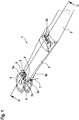
- Figure 1 shows a multi-blade rotor 1 of a rotary wing aircraft, in particular a multi-blade rotor for a main rotor of a helicopter.
- the multi-blade rotor 1 illustratively comprises a plurality of rotor blades. However, for purposes of simplicity and clarity of the drawings, only a single rotor blade is partly shown and referred to by the reference sign 2.
- This rotor blade 2 is equipped with a control cuff 3 that is usable for setting a current pitch or blade angle of the rotor blade 2 in operation.
- the multi-blade rotor 1 is embodied as hinge- and bearingless rotor having a flexbeam element 2a as interface between a rotor hub 4 of the multi-blade rotor 1 and the rotor blade 2.
- the rotor hub 4 is preferably rigidly mounted to a rotor shaft or mast of the hinge- and bearingless rotor 1, or embodied as an integral part thereof. It should, however, be noted that the rotor blade 2 is not shown in greater detail, neither in Figure 1 nor in the remaining figures, for simplicity and clarity of the drawings.
- the flexbeam element 2a is at least partly and, preferably, essentially arranged inside of the control cuff 3.
- One axial end of the flexbeam element 2a is attached to the rotor hub 4 and its other axial end is attached to a root end of the rotor blade 2.
- This root end of the rotor blade 2 is preferably likewise attached to an outer end 3a of the control cuff 3, while an inner end 3b of the control cuff 3 is arranged adjacent to the rotor hub 4.
- control cuff 3 is provided with a lead-lag damper unit 5 having at least two lead-lag dampers 5a, 5b arranged in the region of the inner end 3b of the control cuff 3.
- control cuff 3 is further provided with at least one control rod attachment 6, to which at least one activatable control rod 7 is connected. The latter is activated in operation for rotating the control cuff 3 around its associated longitudinal axis for setting a current pitch or blade angle of the rotor blade 2.
- the inner end 3b is preferably provided with one or more lead-lag damper attachment layers 8. Furthermore, in order to enable attachment of the at least one control rod attachment 6 in the region of the inner end 3b of the control cuff 3, the inner end 3b is provided with a stiffener member 9.
- the one or more lead-lag damper attachment layers 8 are preferentially arranged on an outer circumference of the inner end 3b of the control cuff 3, while the stiffener member 9 is arranged on an inner circumference thereof.
- the control cuff 3 is manufactured as described below with reference to Figure 2 or Figure 3 .
- FIG 2 shows an exemplary method of manufacturing the control cuff 3 of Figure 1 according to one aspect. This method is illustrated with respect to a sectional exploded view of the control cuff 3 of Figure 1 , seen in direction of a sectional line II of Figure 1 .
- an outer shell 10 of the control cuff 3 is manufactured, which is at least to be provided with the stiffener member 9.
- the outer shell 10 is manufactured by means of at least one of a wet-layup, prepreg, infusion and injection process.
- the stiffener member 9 is manufactured by means of an automated process.
- manufacturing of the stiffener member 9 can be performed completely independent of the manufacturing of the outer shell 10, i. e. prior to, simultaneously with or after manufacturing of the outer shell 10.
- the step of manufacturing the stiffener member 9 by means of an automated process comprises manufacturing the stiffener member 9 as a composite component using automated fiber winding technology.
- fibers can be used instead of fiber layers of multi-axial layers, so that an otherwise required pre-manufacturing process can be avoided and costs can be saved.
- the step of manufacturing the stiffener member 9 by means of an automated process is not limited to use of automated fiber winding and that other manufacturing processes are likewise contemplated, such as e. g. manufacturing the stiffener member 9 as a metal component using automated 3D printing or manufacturing the stiffener member 9 as a metal component using automated 3D milling.
- the stiffener member 9 is preferably pre-manufactured, preferentially in the form of a stiffener belt or ring 9a, and provided as a separate component, which must subsequently be mounted to the outer shell 10.
- Mounting of the stiffener member 9 comprises securely fixing the stiffener member 9 in the outer shell 10. More specifically, according to one aspect, the stiffener member 9 is inserted into the outer shell 10, as illustrated with an arrow 12. Preferably, the stiffener member 9 is located, as described above with reference to Figure 1 , at the inner end 3b of the control cuff 3. Illustratively, the outer shell 10 and the stiffener member 9 are at least partly conically shaped. The stiffener member 9 is then bonded to the outer shell 10. An adhesive 11 is applied on an outer surface of the stiffener member 9 prior to inserting the stiffener member 9 into the outer shell 10, as indicated in Figure 1 . Thus, the stiffener member 9 can be bonded to the outer shell 10 by means of the adhesive 11. Preferentially, the adhesive 11 is applied to the outer surface or outer circumference of the stiffener member 9 in the form of an adhesive line so that the adhesive line forms at least partly an adhesive ring around the belt- or ring-shaped stiffener member 9.
- At least one lead-lag damper attachment layer 8 is created on the outer shell 10. This can be done in any suitable manner, even one that is already well-known to the person skilled in the art, and is illustratively performed prior to bonding of the stiffener member 9 to the outer shell 10. However, the at least one lead-lag damper attachment layer 8 can also be provided, i. e. created after the bonding is finished.
- the at least one lead-lag damper attachment layer 8 provided on the outer shell 10 is milled into a shape 8a that is adapted for attachment of the lead-lag dampers 5a, 5b of Figure 1 .
- This can also be done in any suitable manner, even one that is already well-known to the person skilled in the art.
- the lead-lag dampers 5a, 5b are then attached to the at least one lead-lag damper attachment layer 8.
- Figure 3 shows an alternative method of manufacturing the control cuff 3 of Figure 1 .
- This alternative method essentially corresponds to the method described above with reference to Figure 2 and is also illustrated with respect to a sectional exploded view of the control cuff 3 of Figure 1 , seen in direction of the sectional line II of Figure 1 .
- the stiffener member 9 now comprises an injection channel 9b on its outer surface or outer circumference. More specifically, the stiffener member 9, which is preferably again provided as the stiffener belt or ring 9a of Figure 2 , now preferentially comprises an annular groove on its outer surface or outer circumference that defines the injection channel 9b. This injection channel 9b is preferably created during the automated fiber winding of the stiffener member 9, as described above with reference to Figure 2 .
- the stiffener member 9 with the injection channel 9b is inserted into the outer shell 10 of the control cuff 3, preferably in direction of the arrow 12 of Figure 2 and prior to applying an adhesive thereto. It should be noted that the stiffener member 9 is shown twice in Figure 3 : one time on the outside of the outer shell 10, i. e. on the left hand side of Figure 3 , for clearly illustrating the injection channel 9b, and one time inside of the outer shell 10 for illustrating subsequent method steps.
- the injection channel 9b is defined such that after insertion of the stiffener member 9 into the outer shell 10 a bonding gap 13 occurs between the stiffener member 9 and the outer shell 10. More specifically, the bonding gap 13 is preferentially created between an inner surface of the outer shell 10 and an outer surface of the stiffener member 9 by means of the injection channel 9b when inserting the stiffener member 9 into the outer shell 10.
- the outer shell 10 is provided with an adhesive feed line 14, which is preferably connected with the injection channel 9b through a suitable opening in the outer shell 10.
- This suitable opening is preferentially embodied in the region of the injection channel 9b and, illustratively, traversing the lead-lag damper attachment layers 8.
- an outer surface or outer circumference of the outer shell 10 can be shaped according to predetermined shaping parameters. This can e. g. be done by means of an automated milling process, which is well-known to the person skilled in the art.
Description
- The invention is related to a method of manufacturing a control cuff for a rotor blade for a hinge- and bearingless rotor, the method comprising at least the features of claim 1. The invention is further related to a rotor blade of a hinge- and bearingless rotor with a control cuff that is manufactured according to such a method.
- In a hinge- and bearingless rotor system, a flexbeam unit is used to connect rotor blades of a multi-blade rotor of a rotary wing aircraft to an associated rotor shaft of the aircraft. During operation, i. e. rotation of the multi-blade rotor, which is hereinafter also referred to as a hinge- and bearingless rotor, the flexbeam unit must withstand and transfer tremendous centrifugal forces that the rotor blades apply thereto, while permitting their flapping, pitch and lead-lag motions. Therefore, the flexbeam unit comprises special, in particular fiber reinforced composite material flexbeam elements that are flexible enough in torsion to allow twisting for blade movement without discrete bearings in the case of a hinge- and bearingless rotor system.
- These flexbeam elements usually possess lead-lag-soft regions that permit motions of associated rotor blades in a hinge- and bearingless rotor system in the lead-lag direction. The lead-lag-soft regions thus constitute fictitious vertically oriented axes, so-called virtual lead-lag hinges, about which the rotor blades execute forward and backward lead-lag motions. Furthermore, these flexbeam elements realize flapwise-soft regions that enable flapping of the associated rotor blades in the vertical direction and, thus, constitute fictitious horizontally oriented axes, so-called virtual flapping hinges, about which the associated rotor blades execute upward and downward flapwise motions in a hinge- and bearingless rotor system. The distance between these virtual flapping hinges and the axis of the rotor shaft is referred to as the flapping hinge distance.
- Moreover, in a hinge- and bearingless rotor system, these flexbeam elements usually comprise torsion weak regions which enable low-force torsional motion of the flexbeam elements for inducing pitch angle adjustments of the rotor blades, and which allow limiting an associated length of the flexbeam elements. Such torsion weak regions must be resistant against lead-lag and flap shear forces and provide a required stiffness in lead-lag and flapping direction for dynamic reasons. Furthermore, such torsion weak regions should have a small cross section in order to reduce an associated drag of these regions.
- For controlling an associated torsion of the torsion weak regions of the flexbeam elements in order to set a current pitch or blade angle of the rotor blades, suitable control cuffs, which are also referred to as pitch horns, are associated with the flexbeam elements and, in particular, with the torsion weak regions. Each control cuff is usually connected to associated control rods that are controlled by suitable servo hydraulic actuators for adjusting the current pitch or blade angle of a given rotor blade in operation.
- With respect to the multi-blade rotor of the rotary wing aircraft, the control cuffs are connected to associated root ends of the rotor blades and associated flexbeam heads of the flexbeam elements at predetermined disconnecting points provided at the flexbeam heads of the flexbeam elements. An underlying radial position of these disconnecting points with respect to the rotor shaft of the multi-blade rotor is mainly defined by a given axial length of the control cuffs and the flexbeam elements, and is usually located at a comparatively high radial distance from the rotor shaft.
- As the control cuffs cause a disturbance of an aerodynamic airflow at the multi-blade rotor, which disturbance increases with the radial distance of the disconnecting points from the rotor shaft, the given axial length of the control cuffs and their projected profile need to be reduced in order to reduce an associated aerodynamic drag. However, reducing the given axial length of the control cuffs inherently implies reducing an underlying axial length of the flexbeam elements, so that comparatively short and compact flexbeam elements can be provided which allow for a high torsion angle per length unit.
- Usually, control cuffs comprise special, in particular fiber reinforced composite material and are manufactured by means of a labor intensive prepreg hand layup method or an infusion process method using preforms. Both methods are, however, only automatable to a certain level and the manufacturing of required stiffener layers, which are mandatory for a required stiffness, constitutes the most time consuming processing part. However, interruption of underlying uni-directional fiber layers in the prepreg hand layup method potentially weakens the control cuffs, so that more layers are necessary for obtaining a required stiffness.
- The document
US 5 462 408 describes a method of manufacturing a control cuff by means of injection molding from a composite of short reinforcing carbon fibers that are embedded in a polyetheretherketone (PEEK) matrix, i. e. in PEEK resin, which is filled to approximately 30% by mass with reinforcing fibers. The control cuff is solidly attached and surrounded, at each of its axial ends, by a ring, made of metal or ceramic, which constitutes a bearing surface for rotation of the cuff in operation. The rings are solidly attached to the control cuff by means of bonding or shrinking. Furthermore, positioning and attachment of the control cuff on an associated rotor blade is achieved by means of the PPK resin. - However, this method of manufacturing requires use of short reinforcing fiber and is, therefore, time consuming and expensive. Furthermore, due to the use of short reinforcing fibers, a hand layup is required and a potential weakening of the control cuff may occur, which must be compensated by providing a comparatively great number of stiffener layers.
- The document
US 2008/0131280 A1 describes a bearingless rotor system that includes a flexbeam assembly having a first beam and a second beam arranged in a back-to-back orientation with a pitch shaft channeled therebetween. The beams extend to an outboard rotor blade station at which the beams morph into a rotor blade spar within an outboard rotor blade section. Both, the flexbeam assembly and the outboard rotor blade station, are surrounded by an essentially contiguous outer aerodynamic skin that provides an aerodynamic surface, but minimizes a torsional stiffness effect, which may resist to a pitch change. - The document
US 4 648 800 A describes a lightweight, resilient, fiber reinforced composite flexbeam. The fiber reinforced composite flexbeam includes a fiber reinforced composite outer structure having torsionally stiff inboard and outboard end portions which taper down to a thin, resilient, torsionally soft, solid web medial portion. The inboard end and outboard end portions are reinforced with either metallic or fiber reinforced composite doublers which enhance the structural integrity at attachment areas and also provide a smooth transition from the torsionally stiff end portions to the torsionally soft, medial portions. - It is, therefore, an object of the present invention to provide a new method of manufacturing a control cuff for a rotor blade of a hinge- and bearingless rotor, which allows at least a reduction of underlying manufacturing costs while allowing manufacturing of a sufficiently stiffened control cuff.
- This object is solved by a method of manufacturing a control cuff for a rotor blade of a hinge- and bearingless rotor, the method comprising at least the steps of claim 1.
- More specifically, according to the present invention a method of manufacturing a control cuff for a rotor blade for a hinge- and bearingless rotor, the control cuff being adapted for accommodation of a flexbeam element of the rotor and comprising a control rod attachment for connection to an activatable control rod that is activatable for rotating the control cuff in operation around its associated longitudinal axis for setting a current pitch or a blade angle of the rotor blade, comprises at least the steps of: manufacturing an outer shell of the control cuff, manufacturing a stiffener member by means of an automated process, inserting the stiffener member into the outer shell, and bonding the stiffener member to the outer shell, in the region of the control rod attachment. Advantageously, by manufacturing the stiffener member by means of an automated process, e. g. by means of fiber winding, respective overall manufacturing costs of the control cuff can be reduced. Furthermore, as the stiffener member is preferably manufactured using endless fibers, less material is required and even cheaper material can be used. Thus, the total costs of the hinge- and bearingless rotor according to the present invention can advantageously by reduced. Furthermore, there is no need to use uni-directional weaved material.
- However, it should be noted that manufacturing of the stiffener member is not restricted to automated fiber winding. Instead, alternative automated manufacturing methods, such as 3D printing or 3D milling of a metal component for manufacturing the stiffener member, can likewise be employed.
- According to a preferred embodiment, the step of manufacturing the stiffener member by means of an automated process comprises manufacturing the stiffener member as a composite component using automated fiber winding technology.
- According to a further preferred embodiment, the step of manufacturing the stiffener member by means of an automated process comprises manufacturing the stiffener member as a metal component using automated 3D printing.
- According to a further preferred embodiment, the step of manufacturing the stiffener member by means of an automated process comprises manufacturing the stiffener member as a metal component using automated 3D milling.
- According to a further preferred embodiment, the step of manufacturing the outer shell comprises manufacturing the outer shell by means of at least one of a wet-layup, prepreg, infusion and injection process.
- According to a further preferred embodiment, the step of manufacturing the outer shell comprises creating at least one lead-lag damper attachment layer on the outer shell.
- According to a further preferred embodiment, creating the at least one lead-lag damper attachment layer on the outer shell comprises milling the at least one lead-lag damper attachment layer into a shape that is adapted for attachment of an associated lead-lag damper.
- According to a further preferred embodiment, the method further comprises the step of applying an adhesive on an outer surface of the stiffener member prior to inserting the stiffener member into the outer shell, wherein the stiffener member is bonded to the outer shell by means of the adhesive.
- According to a further preferred embodiment, the step of applying an adhesive on an outer surface of the stiffener member prior to inserting the stiffener member into the outer shell comprises applying an adhesive line on the outer surface of the stiffener member.
- According to a further preferred embodiment, the step of manufacturing the outer shell comprises providing the outer shell with an adhesive feed line, wherein the step of manufacturing the stiffener member comprises creating an injection channel on an outer surface of the stiffener member.
- According to a further preferred embodiment, the step of inserting the stiffener member into the outer shell comprises creating a bonding gap between an inner surface of the outer shell and an outer surface of the stiffener member by means of the injection channel.
- According to a further preferred embodiment, the step of bonding the stiffener member to the outer shell comprises injecting adhesive via the feed line into the bonding gap.
- According to a further preferred embodiment, the step of manufacturing the stiffener member comprises manufacturing the stiffener member in the form of a stiffener belt.
- According to a further preferred embodiment, the method further comprises the step of shaping an outer surface of the outer shell according to predetermined shaping parameters by means of an automated milling process.
- The invention further provides a rotor blade for a hinge- and bearingless rotor with a control cuff that is manufactured according to the manufacturing method described above.
- Preferred embodiments of the invention are outlined by way of example in the following description with reference to the attached drawings. In these attached drawings, identical or identically functioning components and elements are labeled with identical reference numbers and characters and are, consequently, only described once in the following description.
-
Figure 1 shows a perspective view of a rotor blade of a hinge- and bearingless rotor having a control cuff according to the invention, -
Figure 2 shows a method of manufacturing the control cuff ofFigure 1 according to a first embodiment, and -
Figure 3 shows a method of manufacturing the control cuff ofFigure 1 according to a second embodiment. -
Figure 1 shows a multi-blade rotor 1 of a rotary wing aircraft, in particular a multi-blade rotor for a main rotor of a helicopter. The multi-blade rotor 1 illustratively comprises a plurality of rotor blades. However, for purposes of simplicity and clarity of the drawings, only a single rotor blade is partly shown and referred to by thereference sign 2. Thisrotor blade 2 is equipped with acontrol cuff 3 that is usable for setting a current pitch or blade angle of therotor blade 2 in operation. - According to one aspect, the multi-blade rotor 1 is embodied as hinge- and bearingless rotor having a
flexbeam element 2a as interface between arotor hub 4 of the multi-blade rotor 1 and therotor blade 2. Therotor hub 4 is preferably rigidly mounted to a rotor shaft or mast of the hinge- and bearingless rotor 1, or embodied as an integral part thereof. It should, however, be noted that therotor blade 2 is not shown in greater detail, neither inFigure 1 nor in the remaining figures, for simplicity and clarity of the drawings. - Illustratively, the
flexbeam element 2a is at least partly and, preferably, essentially arranged inside of thecontrol cuff 3. One axial end of theflexbeam element 2a is attached to therotor hub 4 and its other axial end is attached to a root end of therotor blade 2. This root end of therotor blade 2 is preferably likewise attached to anouter end 3a of thecontrol cuff 3, while aninner end 3b of thecontrol cuff 3 is arranged adjacent to therotor hub 4. - According to one aspect, the
control cuff 3 is provided with a lead-lag damper unit 5 having at least two lead-lag dampers inner end 3b of thecontrol cuff 3. According to the invention, thecontrol cuff 3 is further provided with at least onecontrol rod attachment 6, to which at least one activatable control rod 7 is connected. The latter is activated in operation for rotating thecontrol cuff 3 around its associated longitudinal axis for setting a current pitch or blade angle of therotor blade 2. - In order to enable attachment of the lead-
lag dampers inner end 3b of thecontrol cuff 3, theinner end 3b is preferably provided with one or more lead-lag damper attachment layers 8. Furthermore, in order to enable attachment of the at least onecontrol rod attachment 6 in the region of theinner end 3b of thecontrol cuff 3, theinner end 3b is provided with astiffener member 9. The one or more lead-lag damper attachment layers 8 are preferentially arranged on an outer circumference of theinner end 3b of thecontrol cuff 3, while thestiffener member 9 is arranged on an inner circumference thereof. Thecontrol cuff 3 is manufactured as described below with reference toFigure 2 or Figure 3 . -
Figure 2 shows an exemplary method of manufacturing thecontrol cuff 3 ofFigure 1 according to one aspect. This method is illustrated with respect to a sectional exploded view of thecontrol cuff 3 ofFigure 1 , seen in direction of a sectional line II ofFigure 1 . - Initially, an
outer shell 10 of thecontrol cuff 3 is manufactured, which is at least to be provided with thestiffener member 9. Preferably, theouter shell 10 is manufactured by means of at least one of a wet-layup, prepreg, infusion and injection process. - The
stiffener member 9 is manufactured by means of an automated process. Advantageously, manufacturing of thestiffener member 9 can be performed completely independent of the manufacturing of theouter shell 10, i. e. prior to, simultaneously with or after manufacturing of theouter shell 10. - According to one aspect, the step of manufacturing the
stiffener member 9 by means of an automated process comprises manufacturing thestiffener member 9 as a composite component using automated fiber winding technology. Thus, fibers can be used instead of fiber layers of multi-axial layers, so that an otherwise required pre-manufacturing process can be avoided and costs can be saved. - However, it should be noted that the step of manufacturing the
stiffener member 9 by means of an automated process is not limited to use of automated fiber winding and that other manufacturing processes are likewise contemplated, such as e. g. manufacturing thestiffener member 9 as a metal component using automated 3D printing or manufacturing thestiffener member 9 as a metal component using automated 3D milling. In other words, thestiffener member 9 is preferably pre-manufactured, preferentially in the form of a stiffener belt orring 9a, and provided as a separate component, which must subsequently be mounted to theouter shell 10. - Mounting of the
stiffener member 9 comprises securely fixing thestiffener member 9 in theouter shell 10. More specifically, according to one aspect, thestiffener member 9 is inserted into theouter shell 10, as illustrated with anarrow 12. Preferably, thestiffener member 9 is located, as described above with reference toFigure 1 , at theinner end 3b of thecontrol cuff 3. Illustratively, theouter shell 10 and thestiffener member 9 are at least partly conically shaped. Thestiffener member 9 is then bonded to theouter shell 10. An adhesive 11 is applied on an outer surface of thestiffener member 9 prior to inserting thestiffener member 9 into theouter shell 10, as indicated inFigure 1 . Thus, thestiffener member 9 can be bonded to theouter shell 10 by means of the adhesive 11. Preferentially, the adhesive 11 is applied to the outer surface or outer circumference of thestiffener member 9 in the form of an adhesive line so that the adhesive line forms at least partly an adhesive ring around the belt- or ring-shapedstiffener member 9. - Furthermore, according to one aspect at least one lead-lag
damper attachment layer 8 is created on theouter shell 10. This can be done in any suitable manner, even one that is already well-known to the person skilled in the art, and is illustratively performed prior to bonding of thestiffener member 9 to theouter shell 10. However, the at least one lead-lagdamper attachment layer 8 can also be provided, i. e. created after the bonding is finished. - Preferably, the at least one lead-lag
damper attachment layer 8 provided on theouter shell 10 is milled into ashape 8a that is adapted for attachment of the lead-lag dampers Figure 1 . This can also be done in any suitable manner, even one that is already well-known to the person skilled in the art. The lead-lag dampers damper attachment layer 8. -
Figure 3 shows an alternative method of manufacturing thecontrol cuff 3 ofFigure 1 . This alternative method essentially corresponds to the method described above with reference toFigure 2 and is also illustrated with respect to a sectional exploded view of thecontrol cuff 3 ofFigure 1 , seen in direction of the sectional line II ofFigure 1 . - However, in contrast to the method described above with reference to
Figure 2 , thestiffener member 9 now comprises aninjection channel 9b on its outer surface or outer circumference. More specifically, thestiffener member 9, which is preferably again provided as the stiffener belt orring 9a ofFigure 2 , now preferentially comprises an annular groove on its outer surface or outer circumference that defines theinjection channel 9b. Thisinjection channel 9b is preferably created during the automated fiber winding of thestiffener member 9, as described above with reference toFigure 2 . - According to one aspect, the
stiffener member 9 with theinjection channel 9b is inserted into theouter shell 10 of thecontrol cuff 3, preferably in direction of thearrow 12 ofFigure 2 and prior to applying an adhesive thereto. It should be noted that thestiffener member 9 is shown twice inFigure 3 : one time on the outside of theouter shell 10, i. e. on the left hand side ofFigure 3 , for clearly illustrating theinjection channel 9b, and one time inside of theouter shell 10 for illustrating subsequent method steps. - Preferably, the
injection channel 9b is defined such that after insertion of thestiffener member 9 into the outer shell 10 abonding gap 13 occurs between thestiffener member 9 and theouter shell 10. More specifically, thebonding gap 13 is preferentially created between an inner surface of theouter shell 10 and an outer surface of thestiffener member 9 by means of theinjection channel 9b when inserting thestiffener member 9 into theouter shell 10. - Then, the
outer shell 10 is provided with anadhesive feed line 14, which is preferably connected with theinjection channel 9b through a suitable opening in theouter shell 10. This suitable opening is preferentially embodied in the region of theinjection channel 9b and, illustratively, traversing the lead-lag damper attachment layers 8. Thus, by injecting adhesive via thefeed line 14 into thebonding gap 13, thestiffener member 9 can be bonded to theouter shell 10. - It should be noted that the above described, preferred embodiments are merely described to illustrate possible embodiments of the present invention, but not in order to restrict the present invention thereto. Instead, multiple modifications and variations of the invention are possible and should, therefore, also be considered as being part of the invention.
- Furthermore, additional or supplementary method steps for fine-tuning of the
control cuff 3 ofFigure 1 according to the present invention, which can be well-known to the person skilled in the art and which can be performed during or after execution of the method steps described above with reference toFigure 2 and Figure 3 , can also be performed and are likewise considered as being part of the invention. For instance, subsequent to the method steps according toFigure 2 or Figure 3 , an outer surface or outer circumference of theouter shell 10 can be shaped according to predetermined shaping parameters. This can e. g. be done by means of an automated milling process, which is well-known to the person skilled in the art. -
- 1
- hinge- and bearingless main rotor
- 2
- rotor blade
- 2a
- flexbeam element
- 3
- control cuff
- 3a
- outer end of control cuff
- 3b
- inner end of control cuff
- 4
- rotor hub
- 5
- lead-lag damper unit
- 5a, 5b
- lead-lag dampers
- 6
- control rod attachment
- 7
- control rod
- 8
- lead-lag damper attachment layers
- 8a
- attachment layer shape
- 9
- stiffener member
- 9a
- stiffener belt
- 9b
- injection channel
- 10
- control cuff outer shell
- 11
- adhesive
- 12
- insertion direction
- 13
- bonding gap
- 14
- adhesive feed line
Claims (15)
- A method of manufacturing a control cuff (3) for a rotor blade (2) of a hinge- and bearingless rotor (1), the control cuff (3) being adapted for accommodation of a flexbeam element (2a) of the rotor (1) and comprising a control rod attachment (6) for connection to an activatable control rod (7) that is activatable for rotating the control cuff (3) in operation around its associated longitudinal axis for setting a current pitch or a blade angle of the rotor blade (2), the method comprising at least the steps of:- Manufacturing an outer shell (10) of the control cuff (3),- Manufacturing a stiffener member (9) by means of an automated process,- Inserting the stiffener member (9) into the outer shell (10), and- Bonding the stiffener member (9) to the outer shell (10), in the region of the control rod attachment (6).
- The method of claim 1,
characterized in that the step of manufacturing the stiffener member (9) by means of an automated process comprises manufacturing the stiffener member (9) as a composite component using automated fiber winding technology. - The method of claim 1,
characterized in that the step of manufacturing the stiffener member (9) by means of an automated process comprises manufacturing the stiffener member (9) as a metal component using automated 3D printing. - The method of claim 1,
characterized in that the step of manufacturing the stiffener member (9) by means of an automated process comprises manufacturing the stiffener member (9) as a metal component using automated 3D milling. - The method of claim 1,
characterized in that the step of manufacturing the outer shell (10) comprises manufacturing the outer shell (10) by means of at least one of a wet-layup, prepreg, infusion and injection process. - The method of claim 5,
characterized in that the step of manufacturing the outer shell (10) comprises creating at least one lead-lag damper attachment layer (8) on the outer shell (10). - The method of claim 6,
characterized in that creating the at least one lead-lag damper attachment layer (8) on the outer shell (10) comprises milling the at least one lead-lag damper attachment layer (8) into a shape (8a) that is adapted for attachment of an associated lead-lag damper (5a, 5b). - The method of claim 1,
characterized by comprising the step of applying an adhesive (11) on an outer surface of the stiffener member (9) prior to inserting the stiffener member (9) into the outer shell (10), wherein the stiffener member (9) is bonded to the outer shell (10) by means of the adhesive (11). - The method of claim 8,
characterized in that the step of applying an adhesive (11) on an outer surface of the stiffener member (9) prior to inserting the stiffener member (9) into the outer shell (10) comprises applying an adhesive line (11) on the outer surface of the stiffener member (9). - The method of claim 1,
characterized in that the step of manufacturing the outer shell (10) comprises providing the outer shell (10) with an adhesive feed line (14), and wherein the step of manufacturing the stiffener member (9) comprises creating an injection channel (9b) on an outer surface of the stiffener member (9). - The method of claim 10,
characterized in that the step of inserting the stiffener member (9) into the outer shell (10) comprises creating a bonding gap (13) between an inner surface of the outer shell (10) and an outer surface of the stiffener member (9) by means of the injection channel (9b). - The method of claim 11,
characterized in that the step of bonding the stiffener member (9) to the outer shell (10) comprises injecting adhesive via the feed line (14) into the bonding gap (13). - The method of claim 1,
characterized in that the step of manufacturing the stiffener member (9) comprises manufacturing the stiffener member (9) in the form of a stiffener belt (9a). - The method of claim 1,
characterized by comprising the step of shaping an outer surface of the outer shell (10) according to predetermined shaping parameters by means of an automated milling process. - A rotor blade (2) for a hinge- and bearingless rotor (1), the rotor blade (2) comprising a control cuff (3) adapted for accommodation of a flexbeam element (2a) of the rotor (1), characterised in that the control cuff (3) comprises a control rod attachment (6) for connection to an activatable control rod (7) that is activatable for rotating the control cuff (3) in operation around its associated longitudinal axis for setting a current pitch or a blade angle of the rotor blade (2) and in that the control cuff (3) is manufactured according to one of the preceding claims.
Priority Applications (2)
| Application Number | Priority Date | Filing Date | Title |
|---|---|---|---|
| EP16400007.7A EP3225542B1 (en) | 2016-03-30 | 2016-03-30 | A method of manufacturing a control cuff for a rotor blade of a hinge- and bearingless rotor |
| US15/377,416 US10532811B2 (en) | 2016-03-30 | 2016-12-13 | Method of manufacturing a control cuff for a rotor blade of a hinge and bearingless rotor |
Applications Claiming Priority (1)
| Application Number | Priority Date | Filing Date | Title |
|---|---|---|---|
| EP16400007.7A EP3225542B1 (en) | 2016-03-30 | 2016-03-30 | A method of manufacturing a control cuff for a rotor blade of a hinge- and bearingless rotor |
Publications (2)
| Publication Number | Publication Date |
|---|---|
| EP3225542A1 EP3225542A1 (en) | 2017-10-04 |
| EP3225542B1 true EP3225542B1 (en) | 2018-05-09 |
Family
ID=55969090
Family Applications (1)
| Application Number | Title | Priority Date | Filing Date |
|---|---|---|---|
| EP16400007.7A Active EP3225542B1 (en) | 2016-03-30 | 2016-03-30 | A method of manufacturing a control cuff for a rotor blade of a hinge- and bearingless rotor |
Country Status (2)
| Country | Link |
|---|---|
| US (1) | US10532811B2 (en) |
| EP (1) | EP3225542B1 (en) |
Families Citing this family (2)
| Publication number | Priority date | Publication date | Assignee | Title |
|---|---|---|---|---|
| US10787846B2 (en) | 2018-08-03 | 2020-09-29 | General Electric Company | Additively manufactured hinge assembly |
| US11673660B1 (en) * | 2022-05-25 | 2023-06-13 | Beta Air, Llc | Systems and devices for parking a propulsor teeter |
Family Cites Families (8)
| Publication number | Priority date | Publication date | Assignee | Title |
|---|---|---|---|---|
| DE3401737A1 (en) * | 1984-01-19 | 1985-07-25 | Messerschmitt-Bölkow-Blohm GmbH, 8012 Ottobrunn | ROTOR, ESPECIALLY A ROTATING PLANE |
| US4648800A (en) * | 1984-05-15 | 1987-03-10 | United Technologies Corporation | Composite flexbeam for a rotary wing aircraft |
| IL102867A (en) * | 1991-08-28 | 1998-02-08 | United Technologies Corp | Bearingless main motor assembly torque tube and method for fabricating same |
| FR2699498B1 (en) | 1992-12-23 | 1995-03-10 | Eurocopter France | Blade made of thermoplastic composite, in particular for a faired tail rotor of a helicopter, and its manufacturing process. |
| US7695249B2 (en) * | 2006-12-01 | 2010-04-13 | Sikorsky Aircraft Corporation | Bearingless rotor blade assembly for a high speed rotary-wing aircraft |
| EP2722276B1 (en) * | 2012-10-18 | 2015-03-18 | AIRBUS HELICOPTERS DEUTSCHLAND GmbH | Separable blade attachment for a bearingless rotor of a helicopter |
| WO2014074947A2 (en) * | 2012-11-08 | 2014-05-15 | Das, Suman | Systems and methods for additive manufacturing and repair of metal components |
| GB2523810B (en) * | 2014-03-06 | 2018-01-17 | Thinklaser Ltd | Component manufacture |
-
2016
- 2016-03-30 EP EP16400007.7A patent/EP3225542B1/en active Active
- 2016-12-13 US US15/377,416 patent/US10532811B2/en active Active
Non-Patent Citations (1)
| Title |
|---|
| None * |
Also Published As
| Publication number | Publication date |
|---|---|
| US20170283051A1 (en) | 2017-10-05 |
| US10532811B2 (en) | 2020-01-14 |
| EP3225542A1 (en) | 2017-10-04 |
Similar Documents
| Publication | Publication Date | Title |
|---|---|---|
| US10710712B2 (en) | Rotor blade afterbody | |
| EP2832640B1 (en) | Composite flexure for tiltrotor rotor system | |
| US4381902A (en) | Helicopter tail rotor of the elastomerically-mounted composite flexbeam type | |
| EP3281869B1 (en) | A control system for controlling at least collective pitch of rotor blades of a multi-blade rotor in a rotary-wing aircraft | |
| EP3366584A1 (en) | Pitch control device for a ducted tail rotor of a rotorcraft | |
| US20150232175A1 (en) | Broad Goods Composite Yoke for Rotor System | |
| US10464666B2 (en) | Composite reinforced swashplate | |
| EP3225542B1 (en) | A method of manufacturing a control cuff for a rotor blade of a hinge- and bearingless rotor | |
| US9623963B2 (en) | Partly cruciform flexbeam and method of manufacturing such a flexbeam | |
| CN108069030B (en) | Propulsion rotor system for tiltrotor aircraft | |
| EP2894094B1 (en) | Flexbeam unit for a bearingless or a hinge- and bearingless multi-blade rotor of a rotary wing aircraft | |
| US20190017543A1 (en) | Inboard Bearing Assemblies with Anti-Rotation Features | |
| KR101654251B1 (en) | Bar of composite matrix material | |
| CA2877180C (en) | Flexbeam unit for a hingeless or a hinge- and bearingless multi-blade rotor of a rotary wing aircraft | |
| US10518874B2 (en) | Multi-blade rotor for a rotary wing aircraft | |
| EP3042850B1 (en) | Rotor head for a vertical takeoff and landing aircraft | |
| JP6348639B2 (en) | Aircraft with fuselage and compound tail boom | |
| US10442532B2 (en) | Composite swashplate guide for rotorcraft control systems | |
| EP3072814B1 (en) | Rotorcraft tail rotor blade assembly and method of forming the same | |
| US20220348309A1 (en) | Compact fitting for coupling blade to rotor hub | |
| RU2783551C1 (en) | Rotor for aircraft made with possibility of hanging | |
| KR20210116440A (en) | Rotor for hover-capable aircraft |
Legal Events
| Date | Code | Title | Description |
|---|---|---|---|
| PUAI | Public reference made under article 153(3) epc to a published international application that has entered the european phase |
Free format text: ORIGINAL CODE: 0009012 |
|
| STAA | Information on the status of an ep patent application or granted ep patent |
Free format text: STATUS: THE APPLICATION HAS BEEN PUBLISHED |
|
| AK | Designated contracting states |
Kind code of ref document: A1 Designated state(s): AL AT BE BG CH CY CZ DE DK EE ES FI FR GB GR HR HU IE IS IT LI LT LU LV MC MK MT NL NO PL PT RO RS SE SI SK SM TR |
|
| AX | Request for extension of the european patent |
Extension state: BA ME |
|
| 17P | Request for examination filed |
Effective date: 20170914 |
|
| RBV | Designated contracting states (corrected) |
Designated state(s): AL AT BE BG CH CY CZ DE DK EE ES FI FR GB GR HR HU IE IS IT LI LT LU LV MC MK MT NL NO PL PT RO RS SE SI SK SM TR |
|
| GRAP | Despatch of communication of intention to grant a patent |
Free format text: ORIGINAL CODE: EPIDOSNIGR1 |
|
| STAA | Information on the status of an ep patent application or granted ep patent |
Free format text: STATUS: GRANT OF PATENT IS INTENDED |
|
| INTG | Intention to grant announced |
Effective date: 20180125 |
|
| GRAS | Grant fee paid |
Free format text: ORIGINAL CODE: EPIDOSNIGR3 |
|
| GRAA | (expected) grant |
Free format text: ORIGINAL CODE: 0009210 |
|
| STAA | Information on the status of an ep patent application or granted ep patent |
Free format text: STATUS: THE PATENT HAS BEEN GRANTED |
|
| AK | Designated contracting states |
Kind code of ref document: B1 Designated state(s): AL AT BE BG CH CY CZ DE DK EE ES FI FR GB GR HR HU IE IS IT LI LT LU LV MC MK MT NL NO PL PT RO RS SE SI SK SM TR |
|
| REG | Reference to a national code |
Ref country code: GB Ref legal event code: FG4D |
|
| REG | Reference to a national code |
Ref country code: CH Ref legal event code: EP Ref country code: AT Ref legal event code: REF Ref document number: 997365 Country of ref document: AT Kind code of ref document: T Effective date: 20180515 |
|
| REG | Reference to a national code |
Ref country code: DE Ref legal event code: R096 Ref document number: 602016003002 Country of ref document: DE Ref country code: IE Ref legal event code: FG4D |
|
| REG | Reference to a national code |
Ref country code: NL Ref legal event code: MP Effective date: 20180509 |
|
| REG | Reference to a national code |
Ref country code: LT Ref legal event code: MG4D |
|
| PG25 | Lapsed in a contracting state [announced via postgrant information from national office to epo] |
Ref country code: FI Free format text: LAPSE BECAUSE OF FAILURE TO SUBMIT A TRANSLATION OF THE DESCRIPTION OR TO PAY THE FEE WITHIN THE PRESCRIBED TIME-LIMIT Effective date: 20180509 Ref country code: BG Free format text: LAPSE BECAUSE OF FAILURE TO SUBMIT A TRANSLATION OF THE DESCRIPTION OR TO PAY THE FEE WITHIN THE PRESCRIBED TIME-LIMIT Effective date: 20180809 Ref country code: NO Free format text: LAPSE BECAUSE OF FAILURE TO SUBMIT A TRANSLATION OF THE DESCRIPTION OR TO PAY THE FEE WITHIN THE PRESCRIBED TIME-LIMIT Effective date: 20180809 Ref country code: SE Free format text: LAPSE BECAUSE OF FAILURE TO SUBMIT A TRANSLATION OF THE DESCRIPTION OR TO PAY THE FEE WITHIN THE PRESCRIBED TIME-LIMIT Effective date: 20180509 Ref country code: LT Free format text: LAPSE BECAUSE OF FAILURE TO SUBMIT A TRANSLATION OF THE DESCRIPTION OR TO PAY THE FEE WITHIN THE PRESCRIBED TIME-LIMIT Effective date: 20180509 |
|
| PG25 | Lapsed in a contracting state [announced via postgrant information from national office to epo] |
Ref country code: LV Free format text: LAPSE BECAUSE OF FAILURE TO SUBMIT A TRANSLATION OF THE DESCRIPTION OR TO PAY THE FEE WITHIN THE PRESCRIBED TIME-LIMIT Effective date: 20180509 Ref country code: NL Free format text: LAPSE BECAUSE OF FAILURE TO SUBMIT A TRANSLATION OF THE DESCRIPTION OR TO PAY THE FEE WITHIN THE PRESCRIBED TIME-LIMIT Effective date: 20180509 Ref country code: RS Free format text: LAPSE BECAUSE OF FAILURE TO SUBMIT A TRANSLATION OF THE DESCRIPTION OR TO PAY THE FEE WITHIN THE PRESCRIBED TIME-LIMIT Effective date: 20180509 Ref country code: GR Free format text: LAPSE BECAUSE OF FAILURE TO SUBMIT A TRANSLATION OF THE DESCRIPTION OR TO PAY THE FEE WITHIN THE PRESCRIBED TIME-LIMIT Effective date: 20180810 Ref country code: HR Free format text: LAPSE BECAUSE OF FAILURE TO SUBMIT A TRANSLATION OF THE DESCRIPTION OR TO PAY THE FEE WITHIN THE PRESCRIBED TIME-LIMIT Effective date: 20180509 |
|
| REG | Reference to a national code |
Ref country code: AT Ref legal event code: MK05 Ref document number: 997365 Country of ref document: AT Kind code of ref document: T Effective date: 20180509 |
|
| PG25 | Lapsed in a contracting state [announced via postgrant information from national office to epo] |
Ref country code: SK Free format text: LAPSE BECAUSE OF FAILURE TO SUBMIT A TRANSLATION OF THE DESCRIPTION OR TO PAY THE FEE WITHIN THE PRESCRIBED TIME-LIMIT Effective date: 20180509 Ref country code: DK Free format text: LAPSE BECAUSE OF FAILURE TO SUBMIT A TRANSLATION OF THE DESCRIPTION OR TO PAY THE FEE WITHIN THE PRESCRIBED TIME-LIMIT Effective date: 20180509 Ref country code: EE Free format text: LAPSE BECAUSE OF FAILURE TO SUBMIT A TRANSLATION OF THE DESCRIPTION OR TO PAY THE FEE WITHIN THE PRESCRIBED TIME-LIMIT Effective date: 20180509 Ref country code: PL Free format text: LAPSE BECAUSE OF FAILURE TO SUBMIT A TRANSLATION OF THE DESCRIPTION OR TO PAY THE FEE WITHIN THE PRESCRIBED TIME-LIMIT Effective date: 20180509 Ref country code: AT Free format text: LAPSE BECAUSE OF FAILURE TO SUBMIT A TRANSLATION OF THE DESCRIPTION OR TO PAY THE FEE WITHIN THE PRESCRIBED TIME-LIMIT Effective date: 20180509 Ref country code: RO Free format text: LAPSE BECAUSE OF FAILURE TO SUBMIT A TRANSLATION OF THE DESCRIPTION OR TO PAY THE FEE WITHIN THE PRESCRIBED TIME-LIMIT Effective date: 20180509 Ref country code: CZ Free format text: LAPSE BECAUSE OF FAILURE TO SUBMIT A TRANSLATION OF THE DESCRIPTION OR TO PAY THE FEE WITHIN THE PRESCRIBED TIME-LIMIT Effective date: 20180509 |
|
| REG | Reference to a national code |
Ref country code: DE Ref legal event code: R097 Ref document number: 602016003002 Country of ref document: DE |
|
| PG25 | Lapsed in a contracting state [announced via postgrant information from national office to epo] |
Ref country code: SM Free format text: LAPSE BECAUSE OF FAILURE TO SUBMIT A TRANSLATION OF THE DESCRIPTION OR TO PAY THE FEE WITHIN THE PRESCRIBED TIME-LIMIT Effective date: 20180509 |
|
| PLBE | No opposition filed within time limit |
Free format text: ORIGINAL CODE: 0009261 |
|
| STAA | Information on the status of an ep patent application or granted ep patent |
Free format text: STATUS: NO OPPOSITION FILED WITHIN TIME LIMIT |
|
| 26N | No opposition filed |
Effective date: 20190212 |
|
| PG25 | Lapsed in a contracting state [announced via postgrant information from national office to epo] |
Ref country code: ES Free format text: LAPSE BECAUSE OF FAILURE TO SUBMIT A TRANSLATION OF THE DESCRIPTION OR TO PAY THE FEE WITHIN THE PRESCRIBED TIME-LIMIT Effective date: 20180509 |
|
| PG25 | Lapsed in a contracting state [announced via postgrant information from national office to epo] |
Ref country code: MC Free format text: LAPSE BECAUSE OF FAILURE TO SUBMIT A TRANSLATION OF THE DESCRIPTION OR TO PAY THE FEE WITHIN THE PRESCRIBED TIME-LIMIT Effective date: 20180509 |
|
| REG | Reference to a national code |
Ref country code: CH Ref legal event code: PL |
|
| PG25 | Lapsed in a contracting state [announced via postgrant information from national office to epo] |
Ref country code: LU Free format text: LAPSE BECAUSE OF NON-PAYMENT OF DUE FEES Effective date: 20190330 Ref country code: AL Free format text: LAPSE BECAUSE OF FAILURE TO SUBMIT A TRANSLATION OF THE DESCRIPTION OR TO PAY THE FEE WITHIN THE PRESCRIBED TIME-LIMIT Effective date: 20180509 |
|
| REG | Reference to a national code |
Ref country code: BE Ref legal event code: MM Effective date: 20190331 |
|
| PG25 | Lapsed in a contracting state [announced via postgrant information from national office to epo] |
Ref country code: IE Free format text: LAPSE BECAUSE OF NON-PAYMENT OF DUE FEES Effective date: 20190330 Ref country code: CH Free format text: LAPSE BECAUSE OF NON-PAYMENT OF DUE FEES Effective date: 20190331 Ref country code: LI Free format text: LAPSE BECAUSE OF NON-PAYMENT OF DUE FEES Effective date: 20190331 |
|
| PG25 | Lapsed in a contracting state [announced via postgrant information from national office to epo] |
Ref country code: BE Free format text: LAPSE BECAUSE OF NON-PAYMENT OF DUE FEES Effective date: 20190331 |
|
| PG25 | Lapsed in a contracting state [announced via postgrant information from national office to epo] |
Ref country code: TR Free format text: LAPSE BECAUSE OF FAILURE TO SUBMIT A TRANSLATION OF THE DESCRIPTION OR TO PAY THE FEE WITHIN THE PRESCRIBED TIME-LIMIT Effective date: 20180509 |
|
| PG25 | Lapsed in a contracting state [announced via postgrant information from national office to epo] |
Ref country code: MT Free format text: LAPSE BECAUSE OF NON-PAYMENT OF DUE FEES Effective date: 20190330 Ref country code: PT Free format text: LAPSE BECAUSE OF FAILURE TO SUBMIT A TRANSLATION OF THE DESCRIPTION OR TO PAY THE FEE WITHIN THE PRESCRIBED TIME-LIMIT Effective date: 20180910 |
|
| PG25 | Lapsed in a contracting state [announced via postgrant information from national office to epo] |
Ref country code: CY Free format text: LAPSE BECAUSE OF FAILURE TO SUBMIT A TRANSLATION OF THE DESCRIPTION OR TO PAY THE FEE WITHIN THE PRESCRIBED TIME-LIMIT Effective date: 20180509 |
|
| PG25 | Lapsed in a contracting state [announced via postgrant information from national office to epo] |
Ref country code: IS Free format text: LAPSE BECAUSE OF FAILURE TO SUBMIT A TRANSLATION OF THE DESCRIPTION OR TO PAY THE FEE WITHIN THE PRESCRIBED TIME-LIMIT Effective date: 20180909 |
|
| PG25 | Lapsed in a contracting state [announced via postgrant information from national office to epo] |
Ref country code: HU Free format text: LAPSE BECAUSE OF FAILURE TO SUBMIT A TRANSLATION OF THE DESCRIPTION OR TO PAY THE FEE WITHIN THE PRESCRIBED TIME-LIMIT; INVALID AB INITIO Effective date: 20160330 |
|
| PG25 | Lapsed in a contracting state [announced via postgrant information from national office to epo] |
Ref country code: SI Free format text: LAPSE BECAUSE OF FAILURE TO SUBMIT A TRANSLATION OF THE DESCRIPTION OR TO PAY THE FEE WITHIN THE PRESCRIBED TIME-LIMIT Effective date: 20180509 |
|
| PG25 | Lapsed in a contracting state [announced via postgrant information from national office to epo] |
Ref country code: MK Free format text: LAPSE BECAUSE OF FAILURE TO SUBMIT A TRANSLATION OF THE DESCRIPTION OR TO PAY THE FEE WITHIN THE PRESCRIBED TIME-LIMIT Effective date: 20180509 |
|
| PGFP | Annual fee paid to national office [announced via postgrant information from national office to epo] |
Ref country code: FR Payment date: 20230324 Year of fee payment: 8 |
|
| PGFP | Annual fee paid to national office [announced via postgrant information from national office to epo] |
Ref country code: IT Payment date: 20230328 Year of fee payment: 8 Ref country code: GB Payment date: 20230322 Year of fee payment: 8 Ref country code: DE Payment date: 20230321 Year of fee payment: 8 |
|
| P01 | Opt-out of the competence of the unified patent court (upc) registered |
Effective date: 20230530 |