EP3225538A1 - Methods and apparatus for forming and installing insulation blankets in a vehicle compartment - Google Patents
Methods and apparatus for forming and installing insulation blankets in a vehicle compartment Download PDFInfo
- Publication number
- EP3225538A1 EP3225538A1 EP17160037.2A EP17160037A EP3225538A1 EP 3225538 A1 EP3225538 A1 EP 3225538A1 EP 17160037 A EP17160037 A EP 17160037A EP 3225538 A1 EP3225538 A1 EP 3225538A1
- Authority
- EP
- European Patent Office
- Prior art keywords
- insulation
- fastener
- insulation blanket
- blanket
- frame
- Prior art date
- Legal status (The legal status is an assumption and is not a legal conclusion. Google has not performed a legal analysis and makes no representation as to the accuracy of the status listed.)
- Granted
Links
Images




Classifications
-
- B—PERFORMING OPERATIONS; TRANSPORTING
- B64—AIRCRAFT; AVIATION; COSMONAUTICS
- B64C—AEROPLANES; HELICOPTERS
- B64C1/00—Fuselages; Constructional features common to fuselages, wings, stabilising surfaces or the like
- B64C1/40—Sound or heat insulation, e.g. using insulation blankets
- B64C1/403—Arrangement of fasteners specially adapted therefor, e.g. of clips
-
- A—HUMAN NECESSITIES
- A62—LIFE-SAVING; FIRE-FIGHTING
- A62C—FIRE-FIGHTING
- A62C3/00—Fire prevention, containment or extinguishing specially adapted for particular objects or places
- A62C3/07—Fire prevention, containment or extinguishing specially adapted for particular objects or places in vehicles, e.g. in road vehicles
- A62C3/08—Fire prevention, containment or extinguishing specially adapted for particular objects or places in vehicles, e.g. in road vehicles in aircraft
-
- B—PERFORMING OPERATIONS; TRANSPORTING
- B60—VEHICLES IN GENERAL
- B60R—VEHICLES, VEHICLE FITTINGS, OR VEHICLE PARTS, NOT OTHERWISE PROVIDED FOR
- B60R13/00—Elements for body-finishing, identifying, or decorating; Arrangements or adaptations for advertising purposes
- B60R13/08—Insulating elements, e.g. for sound insulation
-
- B—PERFORMING OPERATIONS; TRANSPORTING
- B64—AIRCRAFT; AVIATION; COSMONAUTICS
- B64C—AEROPLANES; HELICOPTERS
- B64C1/00—Fuselages; Constructional features common to fuselages, wings, stabilising surfaces or the like
- B64C1/40—Sound or heat insulation, e.g. using insulation blankets
-
- B—PERFORMING OPERATIONS; TRANSPORTING
- B64—AIRCRAFT; AVIATION; COSMONAUTICS
- B64C—AEROPLANES; HELICOPTERS
- B64C1/00—Fuselages; Constructional features common to fuselages, wings, stabilising surfaces or the like
- B64C1/40—Sound or heat insulation, e.g. using insulation blankets
- B64C1/403—Arrangement of fasteners specially adapted therefor, e.g. of clips
- B64C1/406—Arrangement of fasteners specially adapted therefor, e.g. of clips in combination with supports for lines, e.g. for pipes or cables
-
- B—PERFORMING OPERATIONS; TRANSPORTING
- B60—VEHICLES IN GENERAL
- B60R—VEHICLES, VEHICLE FITTINGS, OR VEHICLE PARTS, NOT OTHERWISE PROVIDED FOR
- B60R13/00—Elements for body-finishing, identifying, or decorating; Arrangements or adaptations for advertising purposes
- B60R13/08—Insulating elements, e.g. for sound insulation
- B60R2013/0807—Arrangements of fasteners or clips specially adapted therefore
-
- Y—GENERAL TAGGING OF NEW TECHNOLOGICAL DEVELOPMENTS; GENERAL TAGGING OF CROSS-SECTIONAL TECHNOLOGIES SPANNING OVER SEVERAL SECTIONS OF THE IPC; TECHNICAL SUBJECTS COVERED BY FORMER USPC CROSS-REFERENCE ART COLLECTIONS [XRACs] AND DIGESTS
- Y02—TECHNOLOGIES OR APPLICATIONS FOR MITIGATION OR ADAPTATION AGAINST CLIMATE CHANGE
- Y02T—CLIMATE CHANGE MITIGATION TECHNOLOGIES RELATED TO TRANSPORTATION
- Y02T50/00—Aeronautics or air transport
- Y02T50/40—Weight reduction
Definitions
- This patent relates generally to insulation blankets and, more particularly, to methods and apparatus for forming and installing insulation blankets in a vehicle compartment.
- Aircraft often include compartments (e.g., a cargo compartment, a passenger compartment, a flight deck, etc.) disposed in a fuselage of the aircraft.
- compartments e.g., a cargo compartment, a passenger compartment, a flight deck, etc.
- Some known aircraft line the fuselage and/or the compartments with insulation to improve the safety and/or comfort within the compartments.
- the aircraft may be lined with insulation to control thermal, moisture, air pressure and/or noise characteristics within the compartments of the aircraft.
- the insulation lining the aircraft includes insulation blankets coupled to ribs of a frame that extend along the fuselage of the aircraft.
- an apparatus in one example, includes an insulation blanket that includes an outer layer, an insulation layer disposed in the outer layer, and a first fastener disposed in the insulation layer.
- the outer layer and the insulation layer are to form to a first channel.
- the first fastener is to receive, via the first channel, a first portion of a vehicle compartment frame to sealingly couple the insulation layer and the outer layer of the insulation blanket to the vehicle compartment frame.
- an apparatus in another example, includes a unitary fastener contained in a flexible insulation blanket to sealingly couple the insulation blanket to an aircraft compartment frame.
- the fastener includes a first leg, a second leg opposite the first leg, and a middle portion extending between the first leg and the second leg.
- the first leg, the second leg, and the middle portion of the fastener define a channel that is to receive the aircraft compartment frame.
- the first leg and the second leg are to engage the aircraft compartment frame to sealingly couple the insulation blanket to the aircraft compartment frame.
- a method in another example, includes disposing fasteners in an insulation layer of an insulation blanket along a first side of the insulation blanket.
- the fasteners are spaced apart from each other along the first side.
- the method includes enclosing the fasteners and the insulation layer in an outer layer to form the insulation blanket and forming the insulation layer and the outer layer to a channel defined by the fasteners extending along the first side of the insulation blanket.
- the channel is to receive a first portion of a vehicle compartment frame to sealingly couple the insulation blanket to the vehicle compartment frame.
- compartments e.g., cargo compartments, passenger compartments, flight decks, etc.
- items e.g., cargo, equipment, etc.
- people e.g., passengers, crew members, etc.
- a cargo compartment, a passenger compartment and/or a flight deck are typically disposed in a fuselage of aircraft.
- some known aircraft line the fuselage and/or the compartments with insulation.
- the compartments of known aircraft are lined with insulation so that passengers, crew members, electrical components, other airline systems, etc. are not exposed to temperatures, air pressures and/or noise levels of other compartments or surfaces of the aircraft.
- the insulation of some known aircraft deters moisture and/or condensation from forming in the compartment that would otherwise result from a quick change in temperature in the compartment.
- some known aircraft include insulation blankets that are positioned side-by-side and/or end-to-end along an outer portion (e.g., an outer frame) of the compartment. That is, the insulation blankets are positioned next to each other (e.g., side-by-side, end-to-end, staggered, etc.) along the outer frame of the compartment to patch together an insulation surface at the outer portion of the compartment.
- gaps form between adjacent insulation blankets and/or between one or more of the insulation blankets and the outer frame of the compartment. Such gaps create fluid passageways in fluid communication with the aircraft compartment that enable air to travel between the vehicle compartment and the surrounding environment external to the aircraft.
- the insulation provided by the insulation blankets is reduced and/or impaired.
- the air traversing through the fluid passageways may expose the passengers, crew members, cargo, and/or flight equipment located in the aircraft compartment to undesirable temperatures, pressures, etc.
- condensation and/or moisture may form within the aircraft compartment.
- the fluid passageways between the insulation blankets and/or the outer frame may result in uncomfortable and/or otherwise undesirable air pressure and/or noise levels in the aircraft compartment.
- Example insulation blankets disclosed herein include a fastener disposed in an insulation layer of the insulation blanket that is to couple the insulation blanket to a frame of a vehicle compartment (e.g., an aircraft compartment). Because the fastener of the example insulation blanket is disposed in the insulation blanket, only a fraction of a thickness of the insulation blanket (e.g., about half the thickness of the insulation blanket) is positioned between the fastener and the frame when the fastener clamps the insulation blanket to the frame. As a result, a clamping pressure acting on that portion of the insulation blanket is increased, thereby enabling the fastener to increase a seal formed between the insulation blanket and the frame.
- a fastener disposed in an insulation layer of the insulation blanket that is to couple the insulation blanket to a frame of a vehicle compartment (e.g., an aircraft compartment). Because the fastener of the example insulation blanket is disposed in the insulation blanket, only a fraction of a thickness of the insulation blanket (e.g., about half the thickness of the insulation blanket) is positioned between
- the insulation layer in which the fastener is disposed provides thermal and/or moisture insulation to the fastener, thereby preventing condensation from forming on the fastener and, thus, in the aircraft compartment.
- the fasteners are composed of a lightweight thermoplastic material to reduce an amount of weight that the fastener adds to an aircraft.
- the insulation blanket may be coupled to the frame of the aircraft compartment without use of additional external components (e.g., external fasteners). As a result, the time required to install the insulation blanket and/or the risk of foreign object debris (FOD) such as misplaced fasteners unintentionally left in the aircraft compartment is significantly reduced.
- FOD foreign object debris
- the example apparatus disclosed herein include an insulation blanket that has an outer layer, an insulation layer disposed in the outer layer, and a fastener (e.g., a first fastener) disposed in the insulation layer.
- the fastener is to receive, via a channel (e.g., a first channel) formed by the outer layer and the insulation layer, a portion (e.g., a first portion) of a vehicle compartment frame to sealingly couple the insulation layer and the outer layer of the insulation blanket to the vehicle compartment frame.
- the vehicle compartment frame may be an aircraft compartment frame disposed in a nacelle of an aircraft.
- the insulation blanket insulates an aircraft compartment to deter fluid from flowing to the interior aircraft compartment from outer structures of the aircraft.
- the outer layer and the insulation layer are composed of flexible materials that enable adjacent portions of the outer layer and the insulation layer (e.g., first and second portions, respectively) to be positioned along an inner surface of the fastener to enable the fastener to couple the insulation blanket to the compartment frame.
- the outer layer is composed of a semi-rigid material positioned along an inner surface of the fastener that enables the outer layer to form a seal with a surface of the compartment frame when fastener couples the insulation blanket to the compartment frame.
- the outer layer is composed of a fire-resistant material to provide flame-penetration resistance to the insulation layer and the fastener.
- the insulation blanket includes a bay blanket and a cap strip that extends along and which is coupled to and/or protrudes from a first side of the bay blanket.
- the cap strip and the bay blanket are formed by the insulation layer and the outer layer, and the cap strip contains the fastener of the insulation blanket.
- the cap strip seals the insulation blanket and the compartment frame via the fastener disposed in the cap strip.
- the fastener of the example apparatus is disposed in the insulation blanket to prevent the fastener from separating from the insulation blanket.
- the fastener may be fixedly coupled to the insulation blanket.
- the fastener is disposed in the insulation layer of the insulation blanket to increase a sealing engagement between the insulation blanket and the compartment frame, for example, to increase thermal insulation, decrease moisture accumulation, increase acoustic insulation, etc. Further, the insulation layer insulates the fastener to prevent condensation from forming on the fastener and, thus, to prevent condensation from forming in the compartment.
- the fastener of the example apparatus disclosed herein is a unitary structure that includes a first leg, a second leg opposite the first leg, and a middle portion extending between the first leg and the second leg.
- the first leg and the second leg are to engage the compartment frame to sealingly couple the insulation blanket to the compartment frame.
- the first leg and the second leg clamp a portion of the insulation blanket to the compartment frame to form a seal between the insulation blanket and the compartment frame.
- the first leg and the second leg initially flex away from each other to enable the fastener to receive the compartment frame and, upon receiving the compartment frame, the first leg and the second leg subsequently flex toward each other to enable the fastener to cause the insulation blanket to sealingly engage the insulation frame.
- the first leg and the second leg enable the fastener to receive and couple to a portion of the vehicle compartment frame having an L-shaped cross-section.
- a plurality of fasteners is disposed in the insulation layer.
- the first fastener and the second fastener extend along the first side of the insulation blanket (e.g., in the cap strip) and are spaced apart from each other.
- the second fastener is to receive a portion (e.g., the first portion) of the compartment frame via another channel (e.g., a second channel) formed by the outer layer and the insulation layer of the insulation blanket.
- the insulation blanket may include a flexible cover film extending and/or protruding from a second side of the insulation blanket (e.g., opposite the cap strip). The cover film is to engage a second portion of the compartment frame that is spaced apart from the first portion and is to be coupled to the second portion via a second insulation blanket (e.g., via a fastener of the second insulation blanket).
- FIG. 1 illustrates an example aircraft 100 including wings 102 (e.g., a right wing and a left wing) extending laterally outward from a fuselage 104.
- wings 102 e.g., a right wing and a left wing
- Each of the wings 102 of the illustrated example supports an aircraft engine 106 via a pylon 108.
- a compartment 110 e.g., a cargo compartment, a passenger compartment, a flight deck, etc.
- FIG. 1 illustrates an example aircraft 100 including wings 102 (e.g., a right wing and a left wing) extending laterally outward from a fuselage 104.
- a compartment 110 e.g., a cargo compartment, a passenger compartment, a flight deck, etc.
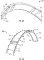
- FIGS. 2A and 2B illustrate an example insulation blanket 200 coupled to a frame 202 as disclosed in the teachings herein.
- the frame 202 is disposed in the fuselage 104 ( FIG. 1 ) of the aircraft 100 ( FIG. 1 ) to define the compartment 110 ( FIG. 1 ) of the aircraft 100.
- the frame 202 includes a first portion 204 (e.g., a first rib) and a second portion 206 (e.g., a second rib) spaced apart from and parallel to the first portion 204.
- the frame 202 is composed of, for example, aluminum and/or any other material that provides structural support for the compartment 100. As illustrated in FIGS.
- the first and second portions 204, 206 of the frame 202 are curved to extend along an arcuate shape of the fuselage 104.
- each of the portions 204, 206 of the frame 202 extends from a first side of the fuselage 104, along a crown (e.g., a roof, an upper portion, etc.), to a second side opposite the first side in a direction perpendicular a longitudinal axis of the fuselage 104.
- the frame 202 defines a compartment of a non-aircraft vehicle (e.g., a train, a bus, a tractor-trailer, etc.) and/or any other compartment or room that is to be insulated.
- the frame 202 is lined with insulation (e.g., the insulation blanket 200) to protect the compartment 110 from undesirable environmental conditions (e.g., temperatures, pressures, condensation, noise levels, etc.).
- the example blanket 200 is coupled to the first and second portions 204, 206 of the frame 202 to cover and, thus, insulate a portion of the frame 202.
- Other insulation blankets substantially similar and/or identical to the insulation blanket 200 are coupled to other portions of the frame 202 to cover and, thus, insulate the other portions of the frame 202.
- a plurality of blankets is positioned end-to-end and side-to-side to cover the frame 202 to insulate the compartment 110.
- an insulation blanket e.g., a second insulation blanket
- another insulation blanket e.g., a third insulation blanket
- the insulation blankets positioned end-to-end relative to each other overlap and couple to each other (e.g., via hook-and-loop fasteners) to prevent fluid passageways from forming between the insulation blankets.
- insulation blankets may be coupled to the frame 202 in a side-by-side manner (e.g., the insulation blanket 200 and an insulation blanket 700 of FIGS. 7 and 8 ) to cover the frame 202 in a longitudinal direction.
- the side-by-side insulation blankets 200, 700 overlap to prevent fluid passageways from forming between the insulation blankets 200, 700.
- the insulation blankets e.g., the insulation blanket 200, the insulation blanket 700, etc.
- the insulation blanket 200 includes a first side 212, a second side 214 opposite the first side 212, and a bay blanket 216 extending between the first side 212 and the second side 214.
- the bay blanket 216 includes insulating material (e.g., an insulation layer 302 of FIG. 3 ) to provide insulation to the frame 202 of the aircraft 100.
- the first side 212 couples to the first portion 204 of the frame 202
- the second side 214 couples to the second portion 206 of the frame 202.
- fasteners 218 e.g., clamps
- that sealingly couple the first side 212 of the insulation blanket 200 to the frame 202 are disposed in the insulation blanket 200 along the first side 212.
- the fasteners 218 extend along the first side 212 of the insulation blanket 200 and are spaced apart from each other.
- each of the example fasteners 218 has a length of about 3 inches and is spaced apart from the adjacent fasteners 218 by about 12 inches.
- the length of and/or the spacing between the fasteners 218 may be greater or smaller depending upon, for example, the thickness of the frame 202, the length of the frame 202, the length of the insulation blanket 200 and/or any other characteristics of the frame 202 and/or the insulation blanket 200 that may affect the sealed coupling between the insulation blanket 200 and the frame 202.
- the fasteners 218 are composed of, for example, a metallic or thermoplastic material that enables the fasteners 218 to flexibly receive the frame 202 and to sealingly clamp the insulation blanket 200 to the frame 202.
- the fasteners 218 are composed of a thermoplastic, the material of the fasteners 218 reduces a weight of the insulation blanket 200 to reduce a weight of the corresponding aircraft 100.
- FIG. 3 is a cross-section of the insulation blanket 200 that depicts one of the fasteners 218, the insulation layer 302, and an outer layer 304 of the insulation blanket 200.
- the insulation layer 302 is disposed in the outer layer 304
- the fastener 218 is disposed in the insulation layer 302.
- the insulation layer 302 is composed of insulating material, such as a fiberglass composite, that provides thermal and noise insulation to the compartment 110 of the aircraft 100 ( FIG. 1 ).
- the outer layer 304 is composed of a fire-resistant material, such as a composite of phenolic resin reinforced with woven fiberglass to prevent fire from contacting, igniting and/or otherwise spreading to the insulation layer 302 and/or other areas of the aircraft 100 outside of the compartment 110.
- the insulation blanket 200 includes the bay blanket 216, a cap strip 306 and a cover film 308.
- the bay blanket 216 is formed by the outer layer 304 and the insulation layer 302 disposed in the outer layer 304 and is positioned between the cap strip 306 and the cover film 308.
- the bay blanket 216 has a thickness 310 defined substantially by the insulation layer 302 to provide insulation to the compartment 110 of the aircraft 100.
- the cap strip 306 is coupled to, extends from and/or protrudes from the bay blanket 216 along the first side 212 of the insulation blanket 200.
- the cap strip 306 is formed by the outer layer 304 and the insulation layer 302 and includes the fastener 218 disposed in the insulation layer 302.
- the fastener 218 is fixedly coupled to a portion of the insulation blanket 200 (e.g., the insulation layer 302, the outer layer 304) in the cap strip 306 of the insulation blanket 200.
- the fastener 218 and the flexible materials of the outer layer 304 and the insulation layer 302 enable the cap strip 306 to sealingly couple to a portion (e.g., the first portion 204 of FIGS.
- the cap strip 306 has a thickness 312 less than the thickness of the bay blanket 310 to enable the cap strip 306 to flexibly engage and sealingly couple to the frame 202.
- the cover film 308 is coupled to, extends from and/or protrudes from the bay blanket 216 along the second side 214 of the insulation blanket 200 opposite the cap strip 306.
- the cover film 308 is composed of, for example, a flexible material that enables the cover film 308 to partially wrap around and engage a portion (e.g., the second portion 206 of FIGS. 2A and 2B ) of the frame 202 to couple the insulation blanket 200 to the frame 202.
- the cover film 308 has a thickness 314 that is significantly less than the thickness 310 of the bay blanket 216 to enable the cap strip 308 to flexibly engage and sealingly couple to the frame 202.
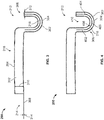
- FIGS. 4 and 5 are partial cross-sections of the first side 212 of the insulation blanket 200. More specifically, FIG. 4 depicts the first side 212 of the insulation blanket 200 uncoupled from the frame 202 ( FIGS. 2A and 2B ), and FIG. 5 depicts the first side 212 coupled to the frame 202.
- the fastener 218 of the cap strip 306 has a U-shaped cross-section prior to coupling to a portion (e.g., the first portion 204 of FIGS. 2A and 2B ) of the frame 202.
- the fastener 218 is a unitary structure that includes a first leg 402, a second leg 404 opposite the first leg 402, and a middle portion 406 connecting the first leg 402 and the second leg 404.
- the fastener 218 may have any other cross-sectional shape (e.g., a V-shaped cross-section, a linear cross-section, etc.) that enables the fastener 218 flexibly engage (e.g., partially wrap around) and/or couple to the portion 204 of the frame 202.
- the insulation layer 302 and the outer layer 304 of the cap strip 306 are positioned along an inner surface 408 of the fastener 218 (e.g., along the inner surface 408 of the first leg 402, the second leg 404, and the middle portion 406) to define or form a channel 410.
- FIG. 5 illustrates the first side 212 of the insulation blanket 200 coupled to the frame 202.
- the channel 410 of the fastener 218 receives and engages the first portion 204 of the frame 202.
- the first leg 402 and the second leg 404 flex away from each other to temporarily expand the channel 410 to enable the fastener 218 to receive the first portion 204 of the frame 202.
- the opposing legs 402, 404 are flexible to enable the fastener 218 to receive (and subsequently sealingly couple to) the first portion 204 of the frame 202 having an L-shaped cross-section.
- the flexibility of the legs 402, 404 enables the fastener 218 to receive other cross-sectional shapes of the frame 202, such as T-shaped cross-sections, I-shaped cross-sections, etc.
- the first leg 402 and the opposing second leg 404 of the fastener 218 flex toward each other to clamp and, thus, sealingly couple the insulation blanket 200 to the frame 202.
- the fastener 218 is composed of a material (e.g., a metallic material, a thermoplastic material) that provides flexibility to enable the fastener 218 to receive frame 202 and provides strength to enable the fastener 218 to securely clamp the insulation blanket 200 to the frame 202.
- the material of the fastener 218 is elastically deformable material to enable the fastener 218 to receive and conform to the shape of the frame 202 to which the fastener 218 couples.
- the material of the fastener 218 is springably flexible to enable the legs 402, 404 of the fastener 218 to flex outward to receive the frame 202 and subsequently spring back to their contracted form to securely and sealingly couple the insulation blanket 200 to the frame 202.
- a fraction of the thickness 312 of the cap strip 306 (i.e., not the entire thickness 312 of the cap strip 306) is positioned between each of the fasteners 218 of the example insulation blanket 200 and the frame 202.
- the fasteners 218 are able to apply an increased clamping pressure to the insulation blanket 200.
- a sealing engagement between the insulation blanket 200 and the frame 202 is increased to improve insulation (e.g., acoustic insulation, thermal insulation, air pressure insulation, etc.) provided to the compartment 110 by the insulation blanket 200.
- the fasteners 208 are provided thermal and/or moisture insulation by the insulation layer 302 to prevent the fasteners 218 from acting as cold sinks that generate and accumulate moisture.
- the example insulation blanket 200 prevents and/or reduces an amount of condensation from forming on the fasteners 218 and, thus, in the compartment 110 of the aircraft 100 ( FIG. 1 ).
- the insulation blanket 200 is couplable to the frame 202 without requiring additional external fasteners. As a result of the reduced number of components needed to install the insulation blanket 200, the installation time of and/or the possibility of foreign object debris (e.g., misplaced external fasteners) in the aircraft 100 is significantly reduced.
- FIG. 6 is a partial cross-section of the second side 214 of the example insulation blanket 200 coupled to the frame 202.
- the cover film 308 engages the second portion 206 of the frame 202 to enable the second side 214 of the insulation blanket 200 to be sealingly coupled to the frame 202.
- the cover film 308 wraps around the second portion 206 of the frame 202 to engage a first side 602 and an opposing second side 604 of the second portion 206.
- the cover film 308 is composed of a flexible material (e.g., a non-fiberglass composite) that enables the cover film 308 to conform to differently shaped portions of the frame 202 (e.g., an L-shaped cross-section illustrated in FIG.
- the cover film 308 is securely coupled to the second portion 206 of the frame 202 via fasteners (e.g., fasteners 806 of FIG. 8 ) of an adjacent insulation blanket (e.g., the insulation blanket 700 of FIGS. 7 and 8 ) to sealingly couple the second side 214 of the insulation blanket 200 to the frame 202.
- the thickness 314 of the cover film 308 is selected to enable the fasteners 806 of the other insulation blanket 700 to securely clamp the cover film 308 to the frame 202.
- the cover film 308 does not extend from the second side 214 of the insulation blanket 200 as illustrated in FIG. 6 .
- another cap strip e.g., substantially similar or identical to the cap strip 306 of FIGS. 3-5
- fasteners e.g., substantially similar or identical to the fasteners 218 of FIGS. 3-5 .
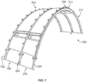
- FIGS. 7 and 8 illustrate the example insulation blanket 200 and the example insulation blanket 700 coupled side-by-side to the frame 202 in accordance with the teachings herein. More specifically, FIG. 7 is a perspective view of the insulation blankets 200, 700 coupled to the frame 202, and FIG. 8 is a cross-sectional view of the insulation blankets 200, 700 coupled to the frame 202.
- Components of the example insulation blanket 200 of FIGS. 7 and 8 are substantially similar or identical to those components having the same reference numbers in FIGS. 2A-6 . Those components are described above in further detail in connection with FIGS. 2A-6 . Further, components of the example blanket 700 of FIGS. 7 and 8 are substantially similar or identical to the components of the example insulation blanket 200. Because the components of the example insulation blanket 200 are described in detail in connection with FIGS. 2A-6 , some characteristics of the corresponding components of the example insulation blanket 700 will not be described in further detail.
- the insulation blanket 200 and the insulation blanket 700 are coupled side-by-side to the frame 202.
- the frame 202 includes the first portion 204 (e.g., the first rib), the second portion 206 (e.g., the second rib) spaced apart from and parallel to the first portion 204, and a third portion 702 (e.g., a third rib) spaced apart from and parallel to the first and second portions 204, 206.
- the first side 212 of the insulation blanket 200 is coupled to the first portion 204, and the second side 214 of the insulation blanket 200 is coupled to the second portion 206.
- a first side 704 of the insulation blanket 700 is coupled to the second portion 206 of the frame 202, and a second side 706 of the insulation blanket 700 opposite the first side 704 is coupled to the third portion 702.
- FIG. 8 further illustrates the insulation blankets 200, 700 coupled to the frame 202 in a side-by-side manner.
- the insulation blanket 200 includes the bay blanket 216, the cap strip 306 extending from and/or coupled to the bay blanket 216 along the first side 212 of the insulation blanket 200, and the cover film 308 extending from and/or coupled to the bay blanket 216 along the opposing second side 214.
- the insulation blanket 700 incudes a bay blanket 802, a cap strip 804 that includes the fasteners 806 and extends from and/or is coupled to the bay blanket 802 along the first side 704 of the insulation blanket 700, and a cover film 808 extending from and/or coupled to the bay blanket 802 along the opposing second side 706.
- the first side 212 of the insulation blanket 200 sealingly couples to the first portion 204 of the frame 202 via the fasteners 218 of the cap strip 306.
- the cover film 308 of the insulation blanket 200 engages the second portion 206
- the fasteners 806 of the cap strip 804 of the insulation blanket 700 extend over the cover film 308, and the fasteners 806 subsequently securely clamp the cover film 308 to the second portion 206.
- the example method 900 for assembling an insulation blanket is discussed in connection with the example insulation blanket 200 of FIGS. 2A-8 and/or the example insulation blanket 700 of FIGS. 7-8 . Further, because the example method 900 may refer to the example insulation blanket 200 of FIGS. 2A-8 and/or the example insulation blanket 700 of FIGS. 7-8 , components identified in FIGS. 2A-8 having functions substantially similar or identical to the functions of components described below will not be described in detail again. Instead, the same reference numbers will be used for like structures.
- the cap strip 804 of FIG. 8 that extends along the first side of the insulation blanket.
- the fastener is positioned in an opening formed in the insulation layer and/or a portion of the insulation layer is wrapped around the fastener. Further, in some examples, the fastener is disposed in the insulation layer such that the fastener is securely coupled to the insulation blanket.
- the example method 900 determines whether there is another fastener to be disposed in the insulation layer. If there is another fastener, blocks 902, 904 are repeated until no other fasteners are identified.
- the insulation layer and the fastener(s) disposed in the insulation layer are enclosed in an outer layer (e.g., the outer layer 304 of FIGS. 3-4 ).
- the insulation layer and the fastener(s) are disposed in the outer layer.
- a cover film e.g., the cover film 308 of FIGS. 3 , 6 , and 8 , the cover film 808 of FIG. 8
- a second side e.g., the second side 214 of FIGS. 2A-3 and 6-8 , the second side 706 of FIGS. 7-8
- the cover film is coupled to the insulation blanket such that the cover film protrudes from and/or extends along the second side.
- FIG. 10 is a flowchart representative of an example method 1000 to couple an insulation blanket to a frame in accordance with the teachings herein.
- example method 1000 is described with reference to the flowchart illustrated in FIG. 10 , many other methods of coupling the insulation blanket to the frame may alternatively be used.
- the order of execution of the blocks may be changed, and/or some of the blocks described changed, eliminated, and/or combined.
- the example method 1000 for coupling an insulation blanket to a frame is discussed in connection with the example insulation blanket 200 of FIGS. 2A-8 , the example insulation blanket 700 of FIGS. 7-8 , and/or the example frame 202 of FIGS. 2A-8 . Further, because the example method 1000 may refer to the example insulation blanket 200 of FIGS. 2A-8 , the example insulation blanket 700 of FIGS. 7-8 , and/or the example frame 202 of FIGS. 2A-8 , components identified in FIGS. 2A-8 having functions substantially similar or identical to the functions of components described below will not be described in detail again. Instead, the same reference numbers will be used for like structures.
- the example method 1000 disclosed herein starts at block 1002 by selecting an insulation blanket (e.g., the insulation blanket 200 of FIGS. 2A-8 , the insulation blanket 700 of FIGS. 7-8 ) to be coupled to a frame (e.g., the frame 202 of FIGS. 2A-2B and 5-8 ).
- a fastener e.g., one of the fasteners 218 of FIGS. 3-5 and 8 , one of the fasteners 806 of FIG. 8
- a portion e.g., the first portion 204 of FIGS. 2A-2B , 5 and 7-8 , the second portion 206 of FIGS. 2A-2B and 6-8 ) of the frame.
- opposing legs e.g., the first and second legs 402, 404 of FIGS. 4-5
- the legs are flexed toward each to clamp the insulation blanket to the frame.
- the example method determines if there is another fastener of the selected insulation blanket that is to be coupled to the portion of the frame. If there is another fastener, blocks 1004, 1006 are repeated until no other fasteners of the selected insulation blanket are identified.
- the example method 1000 includes positioning a cover film (e.g., the cover film 308 of FIGS. 3 , 6 and 8 , the cover film 808 of FIG. 8 ) of the selected insulation blanket to engage another portion (e.g., the second portion 206 of FIGS. 2A-2B and 6-8 , the third portion 702 of FIGS. 7-8 ) of the frame.
- the cover film is positioned to engage the portion to enable fasteners (e.g., the fasteners 218 of FIGS. 3-5 and 8 , the fasteners 806 of FIG. 8 ) of another insulation blanket (e.g., the other of the insulation blankets 200, 700) to couple the cover film to that portion of the frame.
- the example method determines whether there is another insulation blanket to be coupled to the frame. If there is another insulation blanket, blocks 1002, 1004, 1006, 1008, 1010 are repeated until no other insulation blankets are identified.
Landscapes
- Engineering & Computer Science (AREA)
- Mechanical Engineering (AREA)
- Aviation & Aerospace Engineering (AREA)
- Physics & Mathematics (AREA)
- Acoustics & Sound (AREA)
- Health & Medical Sciences (AREA)
- Public Health (AREA)
- Business, Economics & Management (AREA)
- Emergency Management (AREA)
- Thermal Insulation (AREA)
- Vehicle Step Arrangements And Article Storage (AREA)
- Connection Of Plates (AREA)
Abstract
Description
- This patent relates generally to insulation blankets and, more particularly, to methods and apparatus for forming and installing insulation blankets in a vehicle compartment.
- Aircraft often include compartments (e.g., a cargo compartment, a passenger compartment, a flight deck, etc.) disposed in a fuselage of the aircraft. Some known aircraft line the fuselage and/or the compartments with insulation to improve the safety and/or comfort within the compartments. For example, the aircraft may be lined with insulation to control thermal, moisture, air pressure and/or noise characteristics within the compartments of the aircraft. In some instances, the insulation lining the aircraft includes insulation blankets coupled to ribs of a frame that extend along the fuselage of the aircraft.
- In one example, an apparatus includes an insulation blanket that includes an outer layer, an insulation layer disposed in the outer layer, and a first fastener disposed in the insulation layer. The outer layer and the insulation layer are to form to a first channel. The first fastener is to receive, via the first channel, a first portion of a vehicle compartment frame to sealingly couple the insulation layer and the outer layer of the insulation blanket to the vehicle compartment frame.
- In another example, an apparatus includes a unitary fastener contained in a flexible insulation blanket to sealingly couple the insulation blanket to an aircraft compartment frame. The fastener includes a first leg, a second leg opposite the first leg, and a middle portion extending between the first leg and the second leg. The first leg, the second leg, and the middle portion of the fastener define a channel that is to receive the aircraft compartment frame. The first leg and the second leg are to engage the aircraft compartment frame to sealingly couple the insulation blanket to the aircraft compartment frame.
- In another example, a method includes disposing fasteners in an insulation layer of an insulation blanket along a first side of the insulation blanket. The fasteners are spaced apart from each other along the first side. The method includes enclosing the fasteners and the insulation layer in an outer layer to form the insulation blanket and forming the insulation layer and the outer layer to a channel defined by the fasteners extending along the first side of the insulation blanket. The channel is to receive a first portion of a vehicle compartment frame to sealingly couple the insulation blanket to the vehicle compartment frame.
-
-
FIG. 1 depicts an example aircraft in accordance with the teachings herein. -
FIGS. 2A and 2B illustrate an example insulation blanket coupled to a frame in accordance with the teachings herein. -
FIG. 3 is a cross-sectional view of the insulation blanket ofFIGS. 2A and 2B . -
FIG. 4 is a partial cross-sectional view of a first side of the insulation blanket ofFIGS. 2A and 2B . -
FIG. 5 is a partial cross-sectional view of the first side of the insulation blanket ofFIGS. 2A and 2B coupled to a first portion of the frame ofFIGS. 2A and 2B . -
FIG. 6 is a partial cross-sectional view of a second side of the insulation blanket coupled to a second portion of the frame ofFIGS. 2A and 2B . -
FIG. 7 illustrates the example insulation blanket ofFIGS. 2A and 2B and another example insulation blanket coupled to a frame side-by-side in accordance with the teachings herein. -
FIG. 8 is a cross-sectional view of the insulation blankets coupled to the frame ofFIG. 7 . -
FIG. 9 is a flowchart representative of an example method to form the example insulation blanket ofFIGS. 2A-8 and/or the example insulation blanket ofFIGS. 7-8 in accordance with the teachings herein. -
FIG. 10 is a flowchart representative of an example method to install the example insulation blanket ofFIGS. 2A-8 and/or the example insulation blanket ofFIGS. 7-8 in the example aircraft ofFIG. 1 in accordance with the teachings herein. - The figures are not to scale. Instead, to clarify multiple layers and regions, the thicknesses of the layers may be enlarged in the drawings. Wherever possible, the same reference numbers will be used throughout the drawing(s) and accompanying written description to refer to the same or like parts.
- Many known vehicles include compartments (e.g., cargo compartments, passenger compartments, flight decks, etc.) to contain items (e.g., cargo, equipment, etc.) and/or people, (e.g., passengers, crew members, etc.) during travel. For example, a cargo compartment, a passenger compartment and/or a flight deck are typically disposed in a fuselage of aircraft. To increase the safety and/or comfort of the environment in the vehicle compartments, some known aircraft line the fuselage and/or the compartments with insulation. In some examples, the compartments of known aircraft are lined with insulation so that passengers, crew members, electrical components, other airline systems, etc. are not exposed to temperatures, air pressures and/or noise levels of other compartments or surfaces of the aircraft. For example, the insulation of some known aircraft deters moisture and/or condensation from forming in the compartment that would otherwise result from a quick change in temperature in the compartment.
- To insulate a compartment, some known aircraft include insulation blankets that are positioned side-by-side and/or end-to-end along an outer portion (e.g., an outer frame) of the compartment. That is, the insulation blankets are positioned next to each other (e.g., side-by-side, end-to-end, staggered, etc.) along the outer frame of the compartment to patch together an insulation surface at the outer portion of the compartment. In some instances, gaps form between adjacent insulation blankets and/or between one or more of the insulation blankets and the outer frame of the compartment. Such gaps create fluid passageways in fluid communication with the aircraft compartment that enable air to travel between the vehicle compartment and the surrounding environment external to the aircraft.
- As a result, the insulation provided by the insulation blankets is reduced and/or impaired. For example, the air traversing through the fluid passageways may expose the passengers, crew members, cargo, and/or flight equipment located in the aircraft compartment to undesirable temperatures, pressures, etc. Additionally or alternatively, if the temperature in the aircraft compartment and the temperature of the external environment are substantially different (e.g., the surrounding external environment is significantly colder than the temperature in the aircraft compartment), condensation and/or moisture may form within the aircraft compartment. Further, the fluid passageways between the insulation blankets and/or the outer frame may result in uncomfortable and/or otherwise undesirable air pressure and/or noise levels in the aircraft compartment.
- Example insulation blankets disclosed herein include a fastener disposed in an insulation layer of the insulation blanket that is to couple the insulation blanket to a frame of a vehicle compartment (e.g., an aircraft compartment). Because the fastener of the example insulation blanket is disposed in the insulation blanket, only a fraction of a thickness of the insulation blanket (e.g., about half the thickness of the insulation blanket) is positioned between the fastener and the frame when the fastener clamps the insulation blanket to the frame. As a result, a clamping pressure acting on that portion of the insulation blanket is increased, thereby enabling the fastener to increase a seal formed between the insulation blanket and the frame. Further, the insulation layer in which the fastener is disposed provides thermal and/or moisture insulation to the fastener, thereby preventing condensation from forming on the fastener and, thus, in the aircraft compartment. In some examples, the fasteners are composed of a lightweight thermoplastic material to reduce an amount of weight that the fastener adds to an aircraft. Additionally or alternatively, because the fastener is disposed in the insulation blanket, the insulation blanket may be coupled to the frame of the aircraft compartment without use of additional external components (e.g., external fasteners). As a result, the time required to install the insulation blanket and/or the risk of foreign object debris (FOD) such as misplaced fasteners unintentionally left in the aircraft compartment is significantly reduced.
- The example apparatus disclosed herein include an insulation blanket that has an outer layer, an insulation layer disposed in the outer layer, and a fastener (e.g., a first fastener) disposed in the insulation layer. The fastener is to receive, via a channel (e.g., a first channel) formed by the outer layer and the insulation layer, a portion (e.g., a first portion) of a vehicle compartment frame to sealingly couple the insulation layer and the outer layer of the insulation blanket to the vehicle compartment frame. For example, the vehicle compartment frame may be an aircraft compartment frame disposed in a nacelle of an aircraft. In such examples, the insulation blanket insulates an aircraft compartment to deter fluid from flowing to the interior aircraft compartment from outer structures of the aircraft.
- In some examples, the outer layer and the insulation layer are composed of flexible materials that enable adjacent portions of the outer layer and the insulation layer (e.g., first and second portions, respectively) to be positioned along an inner surface of the fastener to enable the fastener to couple the insulation blanket to the compartment frame. In other examples, the outer layer is composed of a semi-rigid material positioned along an inner surface of the fastener that enables the outer layer to form a seal with a surface of the compartment frame when fastener couples the insulation blanket to the compartment frame. Additionally or alternatively, the outer layer is composed of a fire-resistant material to provide flame-penetration resistance to the insulation layer and the fastener.
- In some examples, the insulation blanket includes a bay blanket and a cap strip that extends along and which is coupled to and/or protrudes from a first side of the bay blanket. The cap strip and the bay blanket are formed by the insulation layer and the outer layer, and the cap strip contains the fastener of the insulation blanket. In such examples, the cap strip seals the insulation blanket and the compartment frame via the fastener disposed in the cap strip.
- The fastener of the example apparatus is disposed in the insulation blanket to prevent the fastener from separating from the insulation blanket. To further prevent separation between the fastener and the insulation blanket, the fastener may be fixedly coupled to the insulation blanket. Additionally or alternatively, the fastener is disposed in the insulation layer of the insulation blanket to increase a sealing engagement between the insulation blanket and the compartment frame, for example, to increase thermal insulation, decrease moisture accumulation, increase acoustic insulation, etc. Further, the insulation layer insulates the fastener to prevent condensation from forming on the fastener and, thus, to prevent condensation from forming in the compartment.
- The fastener of the example apparatus disclosed herein is a unitary structure that includes a first leg, a second leg opposite the first leg, and a middle portion extending between the first leg and the second leg. The first leg and the second leg are to engage the compartment frame to sealingly couple the insulation blanket to the compartment frame. For example, the first leg and the second leg clamp a portion of the insulation blanket to the compartment frame to form a seal between the insulation blanket and the compartment frame. To clamp the insulation blanket to the compartment frame, the first leg and the second leg initially flex away from each other to enable the fastener to receive the compartment frame and, upon receiving the compartment frame, the first leg and the second leg subsequently flex toward each other to enable the fastener to cause the insulation blanket to sealingly engage the insulation frame. In some examples, the first leg and the second leg enable the fastener to receive and couple to a portion of the vehicle compartment frame having an L-shaped cross-section.
- In some examples, a plurality of fasteners (e.g., the first fastener, a second fastener, a third fastener, etc.) is disposed in the insulation layer. For example, the first fastener and the second fastener extend along the first side of the insulation blanket (e.g., in the cap strip) and are spaced apart from each other. The second fastener is to receive a portion (e.g., the first portion) of the compartment frame via another channel (e.g., a second channel) formed by the outer layer and the insulation layer of the insulation blanket. Additionally or alternatively, the insulation blanket may include a flexible cover film extending and/or protruding from a second side of the insulation blanket (e.g., opposite the cap strip). The cover film is to engage a second portion of the compartment frame that is spaced apart from the first portion and is to be coupled to the second portion via a second insulation blanket (e.g., via a fastener of the second insulation blanket).
- Turning to the figures,
FIG. 1 illustrates anexample aircraft 100 including wings 102 (e.g., a right wing and a left wing) extending laterally outward from afuselage 104. Each of thewings 102 of the illustrated example supports anaircraft engine 106 via apylon 108. A compartment 110 (e.g., a cargo compartment, a passenger compartment, a flight deck, etc.) is disposed within thefuselage 104 of the illustrated example. -
FIGS. 2A and 2B illustrate anexample insulation blanket 200 coupled to aframe 202 as disclosed in the teachings herein. For example, theframe 202 is disposed in the fuselage 104 (FIG. 1 ) of the aircraft 100 (FIG. 1 ) to define the compartment 110 (FIG. 1 ) of theaircraft 100. In the illustrated example, theframe 202 includes a first portion 204 (e.g., a first rib) and a second portion 206 (e.g., a second rib) spaced apart from and parallel to thefirst portion 204. Theframe 202 is composed of, for example, aluminum and/or any other material that provides structural support for thecompartment 100. As illustrated inFIGS. 2A and 2B , the first andsecond portions frame 202 are curved to extend along an arcuate shape of thefuselage 104. For example, to define thecompartment 110 of theaircraft 100, each of theportions frame 202 extends from a first side of thefuselage 104, along a crown (e.g., a roof, an upper portion, etc.), to a second side opposite the first side in a direction perpendicular a longitudinal axis of thefuselage 104. In other examples, theframe 202 defines a compartment of a non-aircraft vehicle (e.g., a train, a bus, a tractor-trailer, etc.) and/or any other compartment or room that is to be insulated. - The
frame 202 is lined with insulation (e.g., the insulation blanket 200) to protect thecompartment 110 from undesirable environmental conditions (e.g., temperatures, pressures, condensation, noise levels, etc.). For example, theexample blanket 200 is coupled to the first andsecond portions frame 202 to cover and, thus, insulate a portion of theframe 202. Other insulation blankets substantially similar and/or identical to theinsulation blanket 200 are coupled to other portions of theframe 202 to cover and, thus, insulate the other portions of theframe 202. - That is, a plurality of blankets is positioned end-to-end and side-to-side to cover the
frame 202 to insulate thecompartment 110. For example, an insulation blanket (e.g., a second insulation blanket) may be coupled to theframe 202 adjacent afirst end 208 of theinsulation blanket 200 and another insulation blanket (e.g., a third insulation blanket) may be coupled to theframe 202 adjacent asecond end 210 of theinsulation blanket 200 opposite thefirst end 208 in an end-to-end manner to cover theframe 202 in a circumferential direction. The insulation blankets positioned end-to-end relative to each other overlap and couple to each other (e.g., via hook-and-loop fasteners) to prevent fluid passageways from forming between the insulation blankets. - Further, as disclosed in greater detail below with respect to
FIGS. 7 and8 , insulation blankets may be coupled to theframe 202 in a side-by-side manner (e.g., theinsulation blanket 200 and aninsulation blanket 700 ofFIGS. 7 and8 ) to cover theframe 202 in a longitudinal direction. The side-by-side insulation blankets 200, 700 overlap to prevent fluid passageways from forming between the insulation blankets 200, 700. Thus, the insulation blankets (e.g., theinsulation blanket 200, theinsulation blanket 700, etc.) line theframe 202 of theaircraft compartment 110 to maintain safe, comfortable and/or otherwise desirable environmental conditions during flight of theaircraft 100. - As illustrated in
FIGS. 2A and 2B , theinsulation blanket 200 includes afirst side 212, asecond side 214 opposite thefirst side 212, and abay blanket 216 extending between thefirst side 212 and thesecond side 214. For example, thebay blanket 216 includes insulating material (e.g., aninsulation layer 302 ofFIG. 3 ) to provide insulation to theframe 202 of theaircraft 100. Thefirst side 212 couples to thefirst portion 204 of theframe 202, and thesecond side 214 couples to thesecond portion 206 of theframe 202. For example, fasteners 218 (e.g., clamps) that sealingly couple thefirst side 212 of theinsulation blanket 200 to theframe 202 are disposed in theinsulation blanket 200 along thefirst side 212. Thefasteners 218 extend along thefirst side 212 of theinsulation blanket 200 and are spaced apart from each other. In the illustrated example, each of theexample fasteners 218 has a length of about 3 inches and is spaced apart from theadjacent fasteners 218 by about 12 inches. The length of and/or the spacing between thefasteners 218 may be greater or smaller depending upon, for example, the thickness of theframe 202, the length of theframe 202, the length of theinsulation blanket 200 and/or any other characteristics of theframe 202 and/or theinsulation blanket 200 that may affect the sealed coupling between theinsulation blanket 200 and theframe 202. Thefasteners 218 are composed of, for example, a metallic or thermoplastic material that enables thefasteners 218 to flexibly receive theframe 202 and to sealingly clamp theinsulation blanket 200 to theframe 202. In examples in which thefasteners 218 are composed of a thermoplastic, the material of thefasteners 218 reduces a weight of theinsulation blanket 200 to reduce a weight of thecorresponding aircraft 100. -
FIG. 3 is a cross-section of theinsulation blanket 200 that depicts one of thefasteners 218, theinsulation layer 302, and anouter layer 304 of theinsulation blanket 200. As illustrated inFIG. 3 , theinsulation layer 302 is disposed in theouter layer 304, and thefastener 218 is disposed in theinsulation layer 302. Theinsulation layer 302 is composed of insulating material, such as a fiberglass composite, that provides thermal and noise insulation to thecompartment 110 of the aircraft 100 (FIG. 1 ). Theouter layer 304 is composed of a fire-resistant material, such as a composite of phenolic resin reinforced with woven fiberglass to prevent fire from contacting, igniting and/or otherwise spreading to theinsulation layer 302 and/or other areas of theaircraft 100 outside of thecompartment 110. - As illustrated in
FIG. 3 , theinsulation blanket 200 includes thebay blanket 216, acap strip 306 and acover film 308. Thebay blanket 216 is formed by theouter layer 304 and theinsulation layer 302 disposed in theouter layer 304 and is positioned between thecap strip 306 and thecover film 308. Thebay blanket 216 has athickness 310 defined substantially by theinsulation layer 302 to provide insulation to thecompartment 110 of theaircraft 100. - In the illustrated example, the
cap strip 306 is coupled to, extends from and/or protrudes from thebay blanket 216 along thefirst side 212 of theinsulation blanket 200. Thecap strip 306 is formed by theouter layer 304 and theinsulation layer 302 and includes thefastener 218 disposed in theinsulation layer 302. For example, thefastener 218 is fixedly coupled to a portion of the insulation blanket 200 (e.g., theinsulation layer 302, the outer layer 304) in thecap strip 306 of theinsulation blanket 200. As disclosed in further detail below, thefastener 218 and the flexible materials of theouter layer 304 and theinsulation layer 302 enable thecap strip 306 to sealingly couple to a portion (e.g., thefirst portion 204 ofFIGS. 2A and 2B ) of the frame 202 (FIGS. 2A and 2B ) to couple theinsulation blanket 200 to theframe 202. In the illustrated example, thecap strip 306 has athickness 312 less than the thickness of thebay blanket 310 to enable thecap strip 306 to flexibly engage and sealingly couple to theframe 202. - Further, the
cover film 308 is coupled to, extends from and/or protrudes from thebay blanket 216 along thesecond side 214 of theinsulation blanket 200 opposite thecap strip 306. Thecover film 308 is composed of, for example, a flexible material that enables thecover film 308 to partially wrap around and engage a portion (e.g., thesecond portion 206 ofFIGS. 2A and 2B ) of theframe 202 to couple theinsulation blanket 200 to theframe 202. As illustrated inFIG. 3 , thecover film 308 has athickness 314 that is significantly less than thethickness 310 of thebay blanket 216 to enable thecap strip 308 to flexibly engage and sealingly couple to theframe 202. -
FIGS. 4 and5 are partial cross-sections of thefirst side 212 of theinsulation blanket 200. More specifically,FIG. 4 depicts thefirst side 212 of theinsulation blanket 200 uncoupled from the frame 202 (FIGS. 2A and 2B ), andFIG. 5 depicts thefirst side 212 coupled to theframe 202. - In the illustrated example of
FIG. 4 , thefastener 218 of thecap strip 306 has a U-shaped cross-section prior to coupling to a portion (e.g., thefirst portion 204 ofFIGS. 2A and 2B ) of theframe 202. Thefastener 218 is a unitary structure that includes afirst leg 402, asecond leg 404 opposite thefirst leg 402, and amiddle portion 406 connecting thefirst leg 402 and thesecond leg 404. In other examples, because thefastener 218 is composed of flexible material, thefastener 218 may have any other cross-sectional shape (e.g., a V-shaped cross-section, a linear cross-section, etc.) that enables thefastener 218 flexibly engage (e.g., partially wrap around) and/or couple to theportion 204 of theframe 202. As illustrated inFIG. 4 , theinsulation layer 302 and theouter layer 304 of thecap strip 306 are positioned along aninner surface 408 of the fastener 218 (e.g., along theinner surface 408 of thefirst leg 402, thesecond leg 404, and the middle portion 406) to define or form achannel 410. For example, theinsulation layer 302 and theouter layer 304 are composed of flexible materials that enable thefastener 218 to receive and sealingly couple to theportion 204 of theframe 202 to couple thefirst side 212 of theinsulation blanket 200 to theframe 202. In some examples, theouter layer 304 is composed of a semi-rigid material that further increases the seal between theinsulation blanket 200 and theframe 202 when theouter layer 304 engages theframe 202. -
FIG. 5 illustrates thefirst side 212 of theinsulation blanket 200 coupled to theframe 202. As illustrated inFIG. 5 , thechannel 410 of thefastener 218 receives and engages thefirst portion 204 of theframe 202. For example, thefirst leg 402 and thesecond leg 404 flex away from each other to temporarily expand thechannel 410 to enable thefastener 218 to receive thefirst portion 204 of theframe 202. In the illustrated example, the opposinglegs fastener 218 to receive (and subsequently sealingly couple to) thefirst portion 204 of theframe 202 having an L-shaped cross-section. Additionally or alternatively, the flexibility of thelegs fastener 218 to receive other cross-sectional shapes of theframe 202, such as T-shaped cross-sections, I-shaped cross-sections, etc. Upon thechannel 410 of thefastener 218 receiving thefirst portion 204 of theframe 202, thefirst leg 402 and the opposingsecond leg 404 of thefastener 218 flex toward each other to clamp and, thus, sealingly couple theinsulation blanket 200 to theframe 202. Thefastener 218 is composed of a material (e.g., a metallic material, a thermoplastic material) that provides flexibility to enable thefastener 218 to receiveframe 202 and provides strength to enable thefastener 218 to securely clamp theinsulation blanket 200 to theframe 202. For example, the material of thefastener 218 is elastically deformable material to enable thefastener 218 to receive and conform to the shape of theframe 202 to which thefastener 218 couples. Additionally or alternatively, the material of thefastener 218 is springably flexible to enable thelegs fastener 218 to flex outward to receive theframe 202 and subsequently spring back to their contracted form to securely and sealingly couple theinsulation blanket 200 to theframe 202. - As illustrated in
FIG. 5 , a fraction of thethickness 312 of the cap strip 306 (i.e., not theentire thickness 312 of the cap strip 306) is positioned between each of thefasteners 218 of theexample insulation blanket 200 and theframe 202. As a result, thefasteners 218 are able to apply an increased clamping pressure to theinsulation blanket 200. Thus, a sealing engagement between theinsulation blanket 200 and theframe 202 is increased to improve insulation (e.g., acoustic insulation, thermal insulation, air pressure insulation, etc.) provided to thecompartment 110 by theinsulation blanket 200. Further, by containing thefasteners 218 in theinsulation layer 302 of theinsulation blanket 200, thefasteners 208 are provided thermal and/or moisture insulation by theinsulation layer 302 to prevent thefasteners 218 from acting as cold sinks that generate and accumulate moisture. As a result, theexample insulation blanket 200 prevents and/or reduces an amount of condensation from forming on thefasteners 218 and, thus, in thecompartment 110 of the aircraft 100 (FIG. 1 ). Additionally or alternatively, by containing thefasteners 218 in theinsulation layer 302, theinsulation blanket 200 is couplable to theframe 202 without requiring additional external fasteners. As a result of the reduced number of components needed to install theinsulation blanket 200, the installation time of and/or the possibility of foreign object debris (e.g., misplaced external fasteners) in theaircraft 100 is significantly reduced. -
FIG. 6 is a partial cross-section of thesecond side 214 of theexample insulation blanket 200 coupled to theframe 202. As illustrated inFIG. 6 , thecover film 308 engages thesecond portion 206 of theframe 202 to enable thesecond side 214 of theinsulation blanket 200 to be sealingly coupled to theframe 202. Thecover film 308 wraps around thesecond portion 206 of theframe 202 to engage afirst side 602 and an opposingsecond side 604 of thesecond portion 206. Thecover film 308 is composed of a flexible material (e.g., a non-fiberglass composite) that enables thecover film 308 to conform to differently shaped portions of the frame 202 (e.g., an L-shaped cross-section illustrated inFIG. 6 , a T-shaped cross-section, an I-shaped cross-section, etc.). As described in further detail below in connection withFIG. 8 , thecover film 308 is securely coupled to thesecond portion 206 of theframe 202 via fasteners (e.g.,fasteners 806 ofFIG. 8 ) of an adjacent insulation blanket (e.g., theinsulation blanket 700 ofFIGS. 7 and8 ) to sealingly couple thesecond side 214 of theinsulation blanket 200 to theframe 202. Thethickness 314 of thecover film 308 is selected to enable thefasteners 806 of theother insulation blanket 700 to securely clamp thecover film 308 to theframe 202. - In other examples, the
cover film 308 does not extend from thesecond side 214 of theinsulation blanket 200 as illustrated inFIG. 6 . Instead, in some such examples, another cap strip (e.g., substantially similar or identical to thecap strip 306 ofFIGS. 3-5 ) extends along thesecond side 214 that couples to thesecond portion 206 of theframe 200 via fasteners (e.g., substantially similar or identical to thefasteners 218 ofFIGS. 3-5 ). -
FIGS. 7 and8 illustrate theexample insulation blanket 200 and theexample insulation blanket 700 coupled side-by-side to theframe 202 in accordance with the teachings herein. More specifically,FIG. 7 is a perspective view of the insulation blankets 200, 700 coupled to theframe 202, andFIG. 8 is a cross-sectional view of the insulation blankets 200, 700 coupled to theframe 202. - Components of the
example insulation blanket 200 ofFIGS. 7 and8 are substantially similar or identical to those components having the same reference numbers inFIGS. 2A-6 . Those components are described above in further detail in connection withFIGS. 2A-6 . Further, components of theexample blanket 700 ofFIGS. 7 and8 are substantially similar or identical to the components of theexample insulation blanket 200. Because the components of theexample insulation blanket 200 are described in detail in connection withFIGS. 2A-6 , some characteristics of the corresponding components of theexample insulation blanket 700 will not be described in further detail. - As illustrated in
FIG. 7 , theinsulation blanket 200 and theinsulation blanket 700 are coupled side-by-side to theframe 202. In the illustrated example, theframe 202 includes the first portion 204 (e.g., the first rib), the second portion 206 (e.g., the second rib) spaced apart from and parallel to thefirst portion 204, and a third portion 702 (e.g., a third rib) spaced apart from and parallel to the first andsecond portions first side 212 of theinsulation blanket 200 is coupled to thefirst portion 204, and thesecond side 214 of theinsulation blanket 200 is coupled to thesecond portion 206. Afirst side 704 of theinsulation blanket 700 is coupled to thesecond portion 206 of theframe 202, and asecond side 706 of theinsulation blanket 700 opposite thefirst side 704 is coupled to thethird portion 702. -
FIG. 8 further illustrates the insulation blankets 200, 700 coupled to theframe 202 in a side-by-side manner. As illustrated inFIG. 8 , theinsulation blanket 200 includes thebay blanket 216, thecap strip 306 extending from and/or coupled to thebay blanket 216 along thefirst side 212 of theinsulation blanket 200, and thecover film 308 extending from and/or coupled to thebay blanket 216 along the opposingsecond side 214. Theinsulation blanket 700 incudes abay blanket 802, acap strip 804 that includes thefasteners 806 and extends from and/or is coupled to thebay blanket 802 along thefirst side 704 of theinsulation blanket 700, and a cover film 808 extending from and/or coupled to thebay blanket 802 along the opposingsecond side 706. - In the illustrated example, the
first side 212 of theinsulation blanket 200 sealingly couples to thefirst portion 204 of theframe 202 via thefasteners 218 of thecap strip 306. To sealingly couple thesecond side 214 of theinsulation blanket 200 to thesecond portion 206 of theframe 202, thecover film 308 of theinsulation blanket 200 engages thesecond portion 206, thefasteners 806 of thecap strip 804 of theinsulation blanket 700 extend over thecover film 308, and thefasteners 806 subsequently securely clamp thecover film 308 to thesecond portion 206. Thus, thecover film 308 of theinsulation blanket 200 and thecap strip 804 of theinsulation blanket 700 enable theinsulation blanket 200 and theinsulation blanket 700 to couple to the same portion of the frame 202 (e.g., thesecond portion 206 of the frame 202) in a side-by-side manner. Further, because thecap strip 804 of theinsulation blanket 700 overlaps thecover film 308 when coupled to thesecond portion 206, the insulation blankets 200, 700 sealingly couple to thesecond portion 206 to prevent and/or substantially reduce the risk of a gap and/or a fluid passageway forming between theadjacent insulation blankets compartment 110 of the aircraft 100 (FIG. 1 ). - Further, as illustrated in
FIG. 8 , thecap strip 804 of theinsulation blanket 700 engages thethird portion 702 of theframe 202 to enable fasteners of another adjacent blanket (e.g., a third insulation blanket identical and/or substantially similar to the insulation blankets 200, 700) to sealingly couple thesecond side 706 of theinsulation blanket 700 to thethird portion 702 of theframe 202. Thus, each insulation blanket (e.g., theinsulation blanket 200, theinsulation blanket 700, the third insulation blanket, etc.) overlaps with adjacent insulation blankets to sealingly couple to theframe 202 via insulated fasteners (e.g., thefasteners 218, thefasteners 806, fasteners of the third insulation blanket, etc.) to increase an amount of insulation provided to thecompartment 110 of theaircraft 100. -
FIG. 9 is a flowchart representative of anexample method 900 to assemble an insulation blanket in accordance with the teachings herein. Although theexample method 900 is described with reference to the flowchart illustrated inFIG. 9 , many other methods of assembling the insulation blanket may alternatively be used. For example, the order of execution of the blocks may be changed, and/or some of the blocks described changed, eliminated, and/or combined. - The
example method 900 for assembling an insulation blanket is discussed in connection with theexample insulation blanket 200 ofFIGS. 2A-8 and/or theexample insulation blanket 700 ofFIGS. 7-8 . Further, because theexample method 900 may refer to theexample insulation blanket 200 ofFIGS. 2A-8 and/or theexample insulation blanket 700 ofFIGS. 7-8 , components identified inFIGS. 2A-8 having functions substantially similar or identical to the functions of components described below will not be described in detail again. Instead, the same reference numbers will be used for like structures. - The
example method 900 disclosed herein starts atblock 902 by disposing a fastener (e.g., one of thefasteners 218 ofFIGS. 3-5 and8 , one of thefasteners 806 ofFIG. 8 ) in an insulation layer (e.g., theinsulation layer 302 ofFIGS. 3-4 ) along a first side (e.g., thefirst side 212 ofFIGS. 2A-5 and7-8 , thefirst side 704 ofFIGS. 7-8 ) of an insulation blanket (e.g., theinsulation blanket 200 ofFIGS. 2A-8 , theinsulation blanket 700 ofFIGS. 7-8 ). For example, the fastener is disposed in a cap strip (e.g., thecap strip 306 ofFIGS. 3-5 and8 , thecap strip 804 ofFIG. 8 ) that extends along the first side of the insulation blanket. In some examples, to dispose the fastener in the insulation layer, the fastener is positioned in an opening formed in the insulation layer and/or a portion of the insulation layer is wrapped around the fastener. Further, in some examples, the fastener is disposed in the insulation layer such that the fastener is securely coupled to the insulation blanket. Atblock 904, theexample method 900 determines whether there is another fastener to be disposed in the insulation layer. If there is another fastener, blocks 902, 904 are repeated until no other fasteners are identified. - At
block 906, the insulation layer and the fastener(s) disposed in the insulation layer are enclosed in an outer layer (e.g., theouter layer 304 ofFIGS. 3-4 ). In other words, atblock 906, the insulation layer and the fastener(s) are disposed in the outer layer. Atblock 908, a cover film (e.g., thecover film 308 ofFIGS. 3 ,6 , and8 , the cover film 808 ofFIG. 8 ) is coupled to a second side (e.g., thesecond side 214 ofFIGS. 2A-3 and6-8 , thesecond side 706 ofFIGS. 7-8 ) of the insulation blanket opposite the first side. For example, the cover film is coupled to the insulation blanket such that the cover film protrudes from and/or extends along the second side. - Further,
FIG. 10 is a flowchart representative of anexample method 1000 to couple an insulation blanket to a frame in accordance with the teachings herein. Although theexample method 1000 is described with reference to the flowchart illustrated inFIG. 10 , many other methods of coupling the insulation blanket to the frame may alternatively be used. For example, the order of execution of the blocks may be changed, and/or some of the blocks described changed, eliminated, and/or combined. - The
example method 1000 for coupling an insulation blanket to a frame is discussed in connection with theexample insulation blanket 200 ofFIGS. 2A-8 , theexample insulation blanket 700 ofFIGS. 7-8 , and/or theexample frame 202 ofFIGS. 2A-8 . Further, because theexample method 1000 may refer to theexample insulation blanket 200 ofFIGS. 2A-8 , theexample insulation blanket 700 ofFIGS. 7-8 , and/or theexample frame 202 ofFIGS. 2A-8 , components identified inFIGS. 2A-8 having functions substantially similar or identical to the functions of components described below will not be described in detail again. Instead, the same reference numbers will be used for like structures. - The
example method 1000 disclosed herein starts atblock 1002 by selecting an insulation blanket (e.g., theinsulation blanket 200 ofFIGS. 2A-8 , theinsulation blanket 700 ofFIGS. 7-8 ) to be coupled to a frame (e.g., theframe 202 ofFIGS. 2A-2B and5-8 ). Atblock 1004, a fastener (e.g., one of thefasteners 218 ofFIGS. 3-5 and8 , one of thefasteners 806 ofFIG. 8 ) of the selected insulation blanket is sealingly coupled to a portion (e.g., thefirst portion 204 ofFIGS. 2A-2B ,5 and7-8 , thesecond portion 206 ofFIGS. 2A-2B and6-8 ) of the frame. For example, to sealingly couple the fastener to the portion of the frame, opposing legs (e.g., the first andsecond legs FIGS. 4-5 ) are flexed away from each other to enable the fastener to receive the portion of the frame and, upon the fastener receiving the frame, the legs are flexed toward each to clamp the insulation blanket to the frame. Atblock 1006, the example method determines if there is another fastener of the selected insulation blanket that is to be coupled to the portion of the frame. If there is another fastener, blocks 1004, 1006 are repeated until no other fasteners of the selected insulation blanket are identified. - At
block 1008, theexample method 1000 includes positioning a cover film (e.g., thecover film 308 ofFIGS. 3 ,6 and8 , the cover film 808 ofFIG. 8 ) of the selected insulation blanket to engage another portion (e.g., thesecond portion 206 ofFIGS. 2A-2B and6-8 , thethird portion 702 ofFIGS. 7-8 ) of the frame. The cover film is positioned to engage the portion to enable fasteners (e.g., thefasteners 218 ofFIGS. 3-5 and8 , thefasteners 806 ofFIG. 8 ) of another insulation blanket (e.g., the other of the insulation blankets 200, 700) to couple the cover film to that portion of the frame. Atblock 1010, the example method determines whether there is another insulation blanket to be coupled to the frame. If there is another insulation blanket, blocks 1002, 1004, 1006, 1008, 1010 are repeated until no other insulation blankets are identified. - Further, the disclosure comprises embodiments according to the following clauses:
- Clause A1. An apparatus comprising:
- an insulation blanket including:
- an outer layer;
- an insulation layer disposed in the outer layer; and
- a first fastener disposed in the insulation layer, the outer layer and the insulation layer to form to a first channel, the first fastener to receive, via the first channel, a first portion of a vehicle compartment frame to sealingly couple the insulation layer and the outer layer of the insulation blanket to the vehicle compartment frame.
- an insulation blanket including:
- Clause A2. The apparatus of clause A1, wherein the vehicle compartment frame is an aircraft compartment frame disposed in a nacelle of an aircraft, the insulation blanket to couple to the aircraft compartment frame to insulate an aircraft compartment to deter fluid from flowing between the aircraft compartment and an exterior of the aircraft.
- Clause A3. The apparatus of clause A1 or A2, wherein the first fastener is disposed in the insulation blanket to prevent the first fastener from separating from the insulation blanket.
- Clause A4. The apparatus of any of clauses A1 to A3, wherein the insulation blanket further includes:
- a bay blanket formed by the outer layer and the insulation layer; and
- a cap strip extending along and coupled to a first side of the bay blanket, the cap strip formed by the outer layer and the insulation layer and including the first fastener, the cap strip to sealiningly couple the insulation blanket to the first portion of the vehicle compartment frame.
- Clause A5. The apparatus of clause A4, further including a flexible cover film extending from a second side of the bay blanket opposite the cap strip, the cover film to engage a second portion of the vehicle compartment frame spaced apart from the first portion of the vehicle compartment frame, the cover film to be coupled to the second portion of the vehicle compartment frame via a second insulation blanket.
- Clause A6. The apparatus of any of clauses A1 to A5, further including a second fastener disposed in the insulation layer, the second fastener and the first fastener extending along a first side of the insulation blanket, the second fastener spaced apart from the first fastener, the second fastener to receive, via a second channel formed by the outer layer and the insulation layer, the first portion of the vehicle compartment frame.
- Clause A7. The apparatus of any of clauses A1 to A6, wherein the first fastener is composed of a thermoplastic material and the outer layer is composed of a fire-resistant material that provides flame-penetration resistance to the first fastener and the insulation layer.
- Clause A8. The apparatus of any of clauses A1 to A7, wherein the first fastener is disposed in the insulation blanket to increase a sealing engagement between the insulation blanket and the vehicle compartment frame to at least one of increase acoustic insulation, increase thermal insulation, and decrease moisture accumulation.
- Clause A9. The apparatus of any of clauses A1 to A8, wherein the outer layer and the insulation layer are composed of flexible materials to enable a first portion of the outer layer and an adjacent second portion of the insulation layer to be positioned along an inner surface of the first fastener to enable the first fastener to couple the insulation blanket to the vehicle compartment frame.
- Clause A10. The apparatus of any of clauses A1 to A9, wherein the outer layer is composed of a semi-rigid material, a portion of outer layer is positioned along an inner surface of the first fastener to enable the first fastener to couple the insulation blanket to the vehicle compartment frame, the semi-rigid material enables the outer layer of the insulation blanket to form a seal with a surface of the vehicle compartment frame.
- Clause A11. An apparatus comprising:
- a unitary fastener contained in a flexible insulation blanket to sealingly couple the insulation blanket to an aircraft compartment frame, the fastener including:
- a first leg;
- a second leg opposite the first leg; and
- a middle portion extending between the first leg and the second leg,
- wherein the first leg, the second leg, and the middle portion of the fastener define a channel that is to receive the aircraft compartment frame, the first leg and the second leg to engage the aircraft compartment frame to sealingly couple the insulation blanket to the aircraft compartment frame.
- a unitary fastener contained in a flexible insulation blanket to sealingly couple the insulation blanket to an aircraft compartment frame, the fastener including:
- Clause A12. The apparatus of clause A11, wherein the fastener is fixedly coupled to the insulation blanket.
- Clause A13. The apparatus of clause A11 or A12, wherein the fastener is contained in a cap strip extending along and protruding from a side of the insulation blanket.
- Clause A14. The apparatus of any of clauses A11 to A13, wherein the first leg and the second leg clamp a portion of the insulation blanket to the aircraft compartment frame to form a seal between the insulation blanket and the aircraft compartment frame.
- Clause A15. The apparatus of any of clauses A11 to A14, wherein the first leg and the second leg are operable to flex away from each other to enable the fastener to receive the aircraft compartment frame and, upon the fastener receiving the aircraft compartment frame, the first leg and the second leg are operable to flex toward each other to enable the fastener to clamp the insulation blanket to the aircraft compartment frame.
- Clause A16. A method comprising:
- disposing fasteners in an insulation layer of an insulation blanket along a first side of the insulation blanket, the fasteners spaced apart from each other along the first side;
- enclosing the fasteners and the insulation layer in an outer layer to form the insulation blanket; and
- forming the insulation layer and the outer layer to a channel defined by the fasteners extending along the first side of the insulation blanket, the channel to receive a first portion of a vehicle compartment frame to sealingly couple the insulation blanket to the vehicle compartment frame.
- Clause A17. The method of clause A16, further including fixedly coupling the fasteners to the insulation layer along the first side of the insulation blanket.
- Clause A18. The method of clause A16 or A17, wherein disposing the fasteners in the insulation layer along the first side of the insulation blanket includes disposing the fasteners in a cap strip that extends along the first side of the insulation blanket.
- Clause A19. The method of any of clauses A16 to A18, further including coupling a cap strip to a second side of the insulation blanket opposite the first side, the cap strip is to engage a second portion of the vehicle compartment frame to enable the second side of the insulation blanket to couple to the second portion of the vehicle compartment frame.
- Clause A20. The method of any of clauses A16 to A19, further including sealingly coupling the first side of the insulation blanket to the first portion of the vehicle compartment frame via the fasteners by receiving the first portion of the vehicle compartment frame in the channel defined by the fasteners.
- Although certain example apparatus have been described herein, the scope of coverage of this patent is not limited thereto. On the contrary, this patent covers all methods, apparatus and articles of manufacture fairly falling within the scope of the amended claims either literally or under doctrine of equivalents.
Claims (15)
- An apparatus comprising:an insulation blanket (200) including:an outer layer (304);an insulation layer (302) disposed in the outer layer (304); anda first fastener (218) disposed in the insulation layer (302), the outer layer (304) and the insulation layer (302) to form to a first channel (410), the first fastener (218) to receive, via the first channel (410), a first portion of a vehicle compartment frame (202) to sealingly couple the insulation layer (302) and the outer layer (304) of the insulation blanket (200) to the vehicle compartment frame (202).
- The apparatus of claim 1, wherein the vehicle compartment frame (202) is an aircraft compartment frame (202) disposed in a nacelle of an aircraft, the insulation blanket (200) to couple to the aircraft compartment frame (202) to insulate an aircraft compartment to deter fluid from flowing between the aircraft compartment and an exterior of the aircraft.
- The apparatus of claim 1 or 2, wherein the first fastener (218) is disposed in the insulation blanket (200) to prevent the first fastener (218) from separating from the insulation blanket (200).
- The apparatus of claim 1, 2, or 3, wherein the insulation blanket (200) further includes:a bay blanket formed by the outer layer (304) and the insulation layer (302); anda cap strip extending along and coupled to a first side of the bay blanket, the cap strip formed by the outer layer (304) and the insulation layer (302) and including the first fastener (218), the cap strip to sealingly couple the insulation blanket (200) to the first portion of the vehicle compartment frame (202).
- The apparatus of claim 4, further including a flexible cover film extending from a second side of the bay blanket opposite the cap strip, the cover film to engage a second portion of the vehicle compartment frame (202) spaced apart from the first portion of the vehicle compartment frame (202), the cover film to be coupled to the second portion of the vehicle compartment frame (202) via a second insulation blanket.
- The apparatus of any of claims 1-5, further including a second fastener disposed in the insulation layer (302), the second fastener and the first fastener (218) extending along a first side of the insulation blanket (200), the second fastener spaced apart from the first fastener (218), the second fastener to receive, via a second channel formed by the outer layer (304) and the insulation layer (302), the first portion of the vehicle compartment frame (202).
- The apparatus of any of claims 1-6, wherein the first fastener (218) is composed of a thermoplastic material and the outer layer (304) is composed of a fire-resistant material that provides flame-penetration resistance to the first fastener (218) and the insulation layer (302).
- The apparatus of any of claims 1-7, wherein the first fastener (218) is disposed in the insulation blanket (200) to increase a sealing engagement between the insulation blanket (200) and the vehicle compartment frame (202) to at least one of increase acoustic insulation, increase thermal insulation, and decrease moisture accumulation.
- The apparatus of any of claims 1-8, wherein the outer layer (304) and the insulation layer (302) are composed of flexible materials to enable a first portion of the outer layer (304) and an adjacent second portion of the insulation layer (302) to be positioned along an inner surface of the first fastener (218) to enable the first fastener (218) to couple the insulation blanket (200) to the vehicle compartment frame (202).
- The apparatus of any of claims 1-9, wherein the outer layer (304) is composed of a semi-rigid material, a portion of outer layer (304) is positioned along an inner surface of the first fastener (218) to enable the first fastener (218) to couple the insulation blanket (200) to the vehicle compartment frame (202), the semi-rigid material enables the outer layer (304) of the insulation blanket (200) to form a seal with a surface of the vehicle compartment frame (202).
- A method comprising:disposing fasteners (218) in an insulation layer (302) of an insulation blanket (200) along a first side of the insulation blanket (200), the fasteners (218) spaced apart from each other along the first side;enclosing the fasteners (218) and the insulation layer (302) in an outer layer (304) to form the insulation blanket (200); andforming the insulation layer (302) and the outer layer (304) to a channel defined by the fasteners (218) extending along the first side of the insulation blanket (200), the channel to receive a first portion of a vehicle compartment frame (202) to sealingly couple the insulation blanket (200) to the vehicle compartment frame (202).
- The method of claim 11, further including fixedly coupling the fasteners (218) to the insulation layer (302) along the first side of the insulation blanket (200).
- The method of claim 11 or 12, wherein disposing the fasteners (218) in the insulation layer (302) along the first side of the insulation blanket (200) includes disposing the fasteners (218) in a cap strip that extends along the first side of the insulation blanket (200).
- The method of claim 11, 12 or 13, further including coupling a cap strip to a second side of the insulation blanket (200) opposite the first side, the cap strip is to engage a second portion of the vehicle compartment frame (202) to enable the second side of the insulation blanket (200) to couple to the second portion of the vehicle compartment frame (202).
- The method of any one of claims 11-14, further including sealingly coupling the first side of the insulation blanket (200) to the first portion of the vehicle compartment frame (202) via the fasteners (218) by receiving the first portion of the vehicle compartment frame (202) in the channel defined by the fasteners (218).
Applications Claiming Priority (1)
| Application Number | Priority Date | Filing Date | Title |
|---|---|---|---|
| US15/084,231 US9988137B2 (en) | 2016-03-29 | 2016-03-29 | Methods and apparatus for forming and installing insulation blankets in a vehicle compartment |
Publications (2)
| Publication Number | Publication Date |
|---|---|
| EP3225538A1 true EP3225538A1 (en) | 2017-10-04 |
| EP3225538B1 EP3225538B1 (en) | 2020-10-28 |
Family
ID=58266431
Family Applications (1)
| Application Number | Title | Priority Date | Filing Date |
|---|---|---|---|
| EP17160037.2A Active EP3225538B1 (en) | 2016-03-29 | 2017-03-09 | Methods and apparatus for forming and installing insulation blankets in a vehicle compartment |
Country Status (4)
| Country | Link |
|---|---|
| US (1) | US9988137B2 (en) |
| EP (1) | EP3225538B1 (en) |
| CA (1) | CA2958692C (en) |
| RU (1) | RU2737079C2 (en) |
Cited By (1)
| Publication number | Priority date | Publication date | Assignee | Title |
|---|---|---|---|---|
| EP3348468A1 (en) * | 2017-01-17 | 2018-07-18 | The Boeing Company | Continuous insulation blanket cap strip assemblies and methods of using same |
Families Citing this family (6)
| Publication number | Priority date | Publication date | Assignee | Title |
|---|---|---|---|---|
| FR3061129B1 (en) * | 2016-12-22 | 2019-05-31 | Airbus Operations | METHOD FOR MANUFACTURING A THERMOPHONIC ISOLATION MODULE FOR AIRCRAFT COMPRISING A BENDING STEP |
| US10814954B2 (en) * | 2017-01-17 | 2020-10-27 | The Boeing Company | Insulation system |
| BR102022001644A2 (en) * | 2021-03-30 | 2022-10-04 | The Boeing Company | INSULATION SYSTEM FOR AN AIRCRAFT FUSELAGE |
| US12480611B2 (en) * | 2021-12-17 | 2025-11-25 | Embraer S.A. | Thermal barrier curtain systems especially useful for thermally isolating interior cabin zones of cargo transport aircraft |
| US12187412B2 (en) * | 2022-02-11 | 2025-01-07 | The Boeing Company | Insulation attachment system |
| JP7732394B2 (en) * | 2022-05-25 | 2025-09-02 | トヨタ紡織株式会社 | Silencer mounting structure |
Citations (4)
| Publication number | Priority date | Publication date | Assignee | Title |
|---|---|---|---|---|
| US5680680A (en) * | 1996-01-02 | 1997-10-28 | The Boeing Company | Removable multifunctional aircraft clip |
| WO2005068290A1 (en) * | 2004-01-05 | 2005-07-28 | Airbus Deutschland Gmbh | Insulation package arrangement for insulating the interior of an aircraft fuselage |
| US20090302154A1 (en) * | 2005-04-28 | 2009-12-10 | Groening Malte | Material for absorbing noise in aircraft |
| US20120234979A1 (en) * | 2011-03-15 | 2012-09-20 | The Boeing Company | Method and system for insulating frame member |
Family Cites Families (31)
| Publication number | Priority date | Publication date | Assignee | Title |
|---|---|---|---|---|
| US2955339A (en) * | 1956-07-11 | 1960-10-11 | Warren S Richardson | Clip |
| US3969863A (en) * | 1974-08-02 | 1976-07-20 | Alderman Robert J | Roof system |
| DE2634596C2 (en) * | 1976-07-31 | 1985-07-25 | Gebr. Happich Gmbh, 5600 Wuppertal | Edge protection profile strip |
| SE430706B (en) * | 1980-09-16 | 1983-12-05 | Byggutveckling Ab | PROCEDURE TO COVER HOUSES AND FACING PREPARATION ELEMENTS FOR PREPARING THE PROCEDURE |
| US4520594A (en) * | 1983-09-19 | 1985-06-04 | U.S. Product Development Company | Door edge guard and method of manufacture |
| SE446999B (en) * | 1984-03-27 | 1986-10-20 | Sabema Material Ab | DEVICE FOR COLLECTION OF INSULATION AND PHASEPUTS |
| US5577688A (en) * | 1994-06-15 | 1996-11-26 | Sloan; Frank P. | Containment systems for insulation, and insulation elements employing such systems |
| US5724780A (en) * | 1995-06-07 | 1998-03-10 | Owens-Corning Fiberglas Technology, Inc. | Metal building roof structure |
| US5697139A (en) * | 1996-02-16 | 1997-12-16 | Gaetke; Hubert J. | Method for retaining partially rolled-up collapsible containers |
| US6579586B1 (en) * | 2000-09-28 | 2003-06-17 | Johns Manville International, Inc. | Encapsulated insulation batt assembly |
| US6886783B2 (en) | 2003-02-20 | 2005-05-03 | The Boeing Company | Quick install insulation |
| US20040221972A1 (en) * | 2003-05-08 | 2004-11-11 | Tomlinson Carroll Finley | Flexible sound absorbing banner mounted on a surface |
| US7883056B2 (en) * | 2004-01-05 | 2011-02-08 | Airbus Deutschland Gmbh | Insulation arrangement for the internal insulation of a vehicle |
| US7530207B2 (en) * | 2004-02-06 | 2009-05-12 | Alan Morrill | Insulation cane |
| US7374132B2 (en) * | 2005-08-23 | 2008-05-20 | Johns Manville | Insulation product and system suitable for use in an aircraft |
| US7367527B2 (en) * | 2005-08-23 | 2008-05-06 | Johns Manville | Reinforced insulation product and system suitable for use in an aircraft |
| US20080000181A1 (en) * | 2005-09-19 | 2008-01-03 | Sillik Francisco J | Support Structures for Insulation and Other Materials |
| US20070090267A1 (en) * | 2005-09-19 | 2007-04-26 | Sillik Francisco J | Support structures for insulation and other materials |
| DE102006023209A1 (en) * | 2006-05-17 | 2007-11-22 | Airbus Deutschland Gmbh | Insulation of an aircraft fuselage structure |
| FR2919637B1 (en) * | 2007-08-02 | 2009-10-02 | Ae2S Sarl | DEVICE FOR REDUCING SOUND POLLUTION AND INSTALLATION COMPRISING SAID DEVICE |
| US20100031598A1 (en) * | 2008-08-05 | 2010-02-11 | Moore Robert W | Fastener blanket |
| US8205309B2 (en) * | 2008-12-08 | 2012-06-26 | The Boeing Company | Clamps for supporting transport system structures |
| US8616498B2 (en) | 2009-03-31 | 2013-12-31 | The Boeing Company | Aircraft insulation systems and methods |
| DE102009030037A1 (en) * | 2009-06-23 | 2010-12-30 | Airbus Operations Gmbh | Insulation package for the insulation of a cabin of a vehicle |
| DE102010052671B4 (en) * | 2010-11-26 | 2017-03-23 | Airbus Operations Gmbh | Insulation arrangement with ventilation openings for aircraft |
| US20120210665A1 (en) * | 2011-02-17 | 2012-08-23 | Strongplus Co., Ltd. | Fireproof Panel Equipped with Coupling Holes and Method of Manufacturing the Same, and Mold for the Fireproof Panel |
| US8662448B2 (en) * | 2011-06-06 | 2014-03-04 | The Boeing Company | System and method for insulating frame member |
| DE102011116357A1 (en) * | 2011-10-19 | 2013-04-25 | GM Global Technology Operations LLC (n. d. Gesetzen des Staates Delaware) | Clamping element and mounting arrangement with clamping element, as well as method of use of the clamping element |
| US9382929B2 (en) * | 2013-01-07 | 2016-07-05 | The Boeing Company | Composite clamp |
| RU138897U1 (en) * | 2013-10-01 | 2014-03-27 | Открытое акционерное общество (ОАО) "Туполев" | MAT CONSTRUCTION FOR HEAT AND SOUND INSULATION (OPTIONS) |
| US9352821B2 (en) * | 2014-02-11 | 2016-05-31 | The Boeing Company | Retaining device for insulation in an aircraft |
-
2016
- 2016-03-29 US US15/084,231 patent/US9988137B2/en active Active
-
2017
- 2017-02-06 RU RU2017103775A patent/RU2737079C2/en active
- 2017-02-22 CA CA2958692A patent/CA2958692C/en active Active
- 2017-03-09 EP EP17160037.2A patent/EP3225538B1/en active Active
Patent Citations (4)
| Publication number | Priority date | Publication date | Assignee | Title |
|---|---|---|---|---|
| US5680680A (en) * | 1996-01-02 | 1997-10-28 | The Boeing Company | Removable multifunctional aircraft clip |
| WO2005068290A1 (en) * | 2004-01-05 | 2005-07-28 | Airbus Deutschland Gmbh | Insulation package arrangement for insulating the interior of an aircraft fuselage |
| US20090302154A1 (en) * | 2005-04-28 | 2009-12-10 | Groening Malte | Material for absorbing noise in aircraft |
| US20120234979A1 (en) * | 2011-03-15 | 2012-09-20 | The Boeing Company | Method and system for insulating frame member |
Cited By (2)
| Publication number | Priority date | Publication date | Assignee | Title |
|---|---|---|---|---|
| EP3348468A1 (en) * | 2017-01-17 | 2018-07-18 | The Boeing Company | Continuous insulation blanket cap strip assemblies and methods of using same |
| US10532801B2 (en) | 2017-01-17 | 2020-01-14 | The Boeing Company | Continuous insulation blanket cap strip assemblies and methods of using same |
Also Published As
| Publication number | Publication date |
|---|---|
| CA2958692C (en) | 2020-09-15 |
| RU2737079C2 (en) | 2020-11-24 |
| RU2017103775A3 (en) | 2020-05-26 |
| EP3225538B1 (en) | 2020-10-28 |
| CA2958692A1 (en) | 2017-09-29 |
| US20170283031A1 (en) | 2017-10-05 |
| RU2017103775A (en) | 2018-08-08 |
| US9988137B2 (en) | 2018-06-05 |
Similar Documents
| Publication | Publication Date | Title |
|---|---|---|
| CA2958692C (en) | Methods and apparatus for forming and installing insulation blankets in a vehicle compartment | |
| US9868545B2 (en) | Primary structure for an attachment pylon with firewall and thermal layers | |
| EP2718181B1 (en) | System and method for insulating a frame member | |
| US9528442B2 (en) | Aircraft engine anti-icing (EAI) barrier assembly, system and method | |
| US10597137B2 (en) | Thermal insulators having cold side flap seals | |
| EP1449764B1 (en) | Quick-install insulation | |
| US10295107B2 (en) | Systems and methods for duct protection | |
| EP3156322B1 (en) | Frame insulation providing enhanced drainage features | |
| US9809296B2 (en) | Aircraft fuselage comprising an outer insulation | |
| US10814954B2 (en) | Insulation system | |
| CA3033021C (en) | Aircraft thermal acoustic insulation blanket | |
| JP2019073262A (en) | Thermal growth management of radome by boundary constraint | |
| US10001232B2 (en) | Systems and methods for duct protection | |
| EP1482228B1 (en) | Fireproof seal | |
| CN112350249B (en) | Protective piece for cable wall or cabin penetration | |
| US11009256B2 (en) | Crack-resistant polymer foam ducts and method of installing same | |
| US11447229B2 (en) | Transport element support system | |
| US20190367151A1 (en) | Sealable securing systems and methods | |
| US20180335168A1 (en) | Grommet | |
| EP2943402B1 (en) | Access door for possible use with a helicopter fuel tank | |
| US9017789B2 (en) | Insulation assemblies for engine housings and associated methods of use and manufacture | |
| DE102021123614A1 (en) | Thermal insulation of a bulkhead frame of an aircraft |
Legal Events
| Date | Code | Title | Description |
|---|---|---|---|
| PUAI | Public reference made under article 153(3) epc to a published international application that has entered the european phase |
Free format text: ORIGINAL CODE: 0009012 |
|
| STAA | Information on the status of an ep patent application or granted ep patent |
Free format text: STATUS: REQUEST FOR EXAMINATION WAS MADE |
|
| 17P | Request for examination filed |
Effective date: 20170309 |
|
| AK | Designated contracting states |
Kind code of ref document: A1 Designated state(s): AL AT BE BG CH CY CZ DE DK EE ES FI FR GB GR HR HU IE IS IT LI LT LU LV MC MK MT NL NO PL PT RO RS SE SI SK SM TR |
|
| AX | Request for extension of the european patent |
Extension state: BA ME |
|
| STAA | Information on the status of an ep patent application or granted ep patent |
Free format text: STATUS: EXAMINATION IS IN PROGRESS |
|
| 17Q | First examination report despatched |
Effective date: 20191010 |
|
| GRAP | Despatch of communication of intention to grant a patent |
Free format text: ORIGINAL CODE: EPIDOSNIGR1 |
|
| STAA | Information on the status of an ep patent application or granted ep patent |
Free format text: STATUS: GRANT OF PATENT IS INTENDED |
|
| INTG | Intention to grant announced |
Effective date: 20200519 |
|
| GRAS | Grant fee paid |
Free format text: ORIGINAL CODE: EPIDOSNIGR3 |
|
| GRAA | (expected) grant |
Free format text: ORIGINAL CODE: 0009210 |
|
| STAA | Information on the status of an ep patent application or granted ep patent |
Free format text: STATUS: THE PATENT HAS BEEN GRANTED |
|
| AK | Designated contracting states |
Kind code of ref document: B1 Designated state(s): AL AT BE BG CH CY CZ DE DK EE ES FI FR GB GR HR HU IE IS IT LI LT LU LV MC MK MT NL NO PL PT RO RS SE SI SK SM TR |
|
| REG | Reference to a national code |
Ref country code: GB Ref legal event code: FG4D |
|
| REG | Reference to a national code |
Ref country code: CH Ref legal event code: EP |
|
| REG | Reference to a national code |
Ref country code: DE Ref legal event code: R096 Ref document number: 602017026161 Country of ref document: DE |
|
| REG | Reference to a national code |
Ref country code: AT Ref legal event code: REF Ref document number: 1327963 Country of ref document: AT Kind code of ref document: T Effective date: 20201115 |
|
| REG | Reference to a national code |
Ref country code: IE Ref legal event code: FG4D |
|
| REG | Reference to a national code |
Ref country code: AT Ref legal event code: MK05 Ref document number: 1327963 Country of ref document: AT Kind code of ref document: T Effective date: 20201028 |
|
| REG | Reference to a national code |
Ref country code: NL Ref legal event code: MP Effective date: 20201028 |
|
| PG25 | Lapsed in a contracting state [announced via postgrant information from national office to epo] |
Ref country code: FI Free format text: LAPSE BECAUSE OF FAILURE TO SUBMIT A TRANSLATION OF THE DESCRIPTION OR TO PAY THE FEE WITHIN THE PRESCRIBED TIME-LIMIT Effective date: 20201028 Ref country code: GR Free format text: LAPSE BECAUSE OF FAILURE TO SUBMIT A TRANSLATION OF THE DESCRIPTION OR TO PAY THE FEE WITHIN THE PRESCRIBED TIME-LIMIT Effective date: 20210129 Ref country code: NL Free format text: LAPSE BECAUSE OF FAILURE TO SUBMIT A TRANSLATION OF THE DESCRIPTION OR TO PAY THE FEE WITHIN THE PRESCRIBED TIME-LIMIT Effective date: 20201028 Ref country code: NO Free format text: LAPSE BECAUSE OF FAILURE TO SUBMIT A TRANSLATION OF THE DESCRIPTION OR TO PAY THE FEE WITHIN THE PRESCRIBED TIME-LIMIT Effective date: 20210128 Ref country code: PT Free format text: LAPSE BECAUSE OF FAILURE TO SUBMIT A TRANSLATION OF THE DESCRIPTION OR TO PAY THE FEE WITHIN THE PRESCRIBED TIME-LIMIT Effective date: 20210301 Ref country code: RS Free format text: LAPSE BECAUSE OF FAILURE TO SUBMIT A TRANSLATION OF THE DESCRIPTION OR TO PAY THE FEE WITHIN THE PRESCRIBED TIME-LIMIT Effective date: 20201028 |
|
| REG | Reference to a national code |
Ref country code: LT Ref legal event code: MG4D |
|
| PG25 | Lapsed in a contracting state [announced via postgrant information from national office to epo] |
Ref country code: SE Free format text: LAPSE BECAUSE OF FAILURE TO SUBMIT A TRANSLATION OF THE DESCRIPTION OR TO PAY THE FEE WITHIN THE PRESCRIBED TIME-LIMIT Effective date: 20201028 Ref country code: IS Free format text: LAPSE BECAUSE OF FAILURE TO SUBMIT A TRANSLATION OF THE DESCRIPTION OR TO PAY THE FEE WITHIN THE PRESCRIBED TIME-LIMIT Effective date: 20210228 Ref country code: LV Free format text: LAPSE BECAUSE OF FAILURE TO SUBMIT A TRANSLATION OF THE DESCRIPTION OR TO PAY THE FEE WITHIN THE PRESCRIBED TIME-LIMIT Effective date: 20201028 Ref country code: PL Free format text: LAPSE BECAUSE OF FAILURE TO SUBMIT A TRANSLATION OF THE DESCRIPTION OR TO PAY THE FEE WITHIN THE PRESCRIBED TIME-LIMIT Effective date: 20201028 Ref country code: BG Free format text: LAPSE BECAUSE OF FAILURE TO SUBMIT A TRANSLATION OF THE DESCRIPTION OR TO PAY THE FEE WITHIN THE PRESCRIBED TIME-LIMIT Effective date: 20210128 Ref country code: AT Free format text: LAPSE BECAUSE OF FAILURE TO SUBMIT A TRANSLATION OF THE DESCRIPTION OR TO PAY THE FEE WITHIN THE PRESCRIBED TIME-LIMIT Effective date: 20201028 Ref country code: ES Free format text: LAPSE BECAUSE OF FAILURE TO SUBMIT A TRANSLATION OF THE DESCRIPTION OR TO PAY THE FEE WITHIN THE PRESCRIBED TIME-LIMIT Effective date: 20201028 |
|
| PG25 | Lapsed in a contracting state [announced via postgrant information from national office to epo] |
Ref country code: HR Free format text: LAPSE BECAUSE OF FAILURE TO SUBMIT A TRANSLATION OF THE DESCRIPTION OR TO PAY THE FEE WITHIN THE PRESCRIBED TIME-LIMIT Effective date: 20201028 |
|
| REG | Reference to a national code |
Ref country code: DE Ref legal event code: R097 Ref document number: 602017026161 Country of ref document: DE |
|
| PG25 | Lapsed in a contracting state [announced via postgrant information from national office to epo] |
Ref country code: LT Free format text: LAPSE BECAUSE OF FAILURE TO SUBMIT A TRANSLATION OF THE DESCRIPTION OR TO PAY THE FEE WITHIN THE PRESCRIBED TIME-LIMIT Effective date: 20201028 Ref country code: SM Free format text: LAPSE BECAUSE OF FAILURE TO SUBMIT A TRANSLATION OF THE DESCRIPTION OR TO PAY THE FEE WITHIN THE PRESCRIBED TIME-LIMIT Effective date: 20201028 Ref country code: CZ Free format text: LAPSE BECAUSE OF FAILURE TO SUBMIT A TRANSLATION OF THE DESCRIPTION OR TO PAY THE FEE WITHIN THE PRESCRIBED TIME-LIMIT Effective date: 20201028 Ref country code: EE Free format text: LAPSE BECAUSE OF FAILURE TO SUBMIT A TRANSLATION OF THE DESCRIPTION OR TO PAY THE FEE WITHIN THE PRESCRIBED TIME-LIMIT Effective date: 20201028 Ref country code: SK Free format text: LAPSE BECAUSE OF FAILURE TO SUBMIT A TRANSLATION OF THE DESCRIPTION OR TO PAY THE FEE WITHIN THE PRESCRIBED TIME-LIMIT Effective date: 20201028 Ref country code: RO Free format text: LAPSE BECAUSE OF FAILURE TO SUBMIT A TRANSLATION OF THE DESCRIPTION OR TO PAY THE FEE WITHIN THE PRESCRIBED TIME-LIMIT Effective date: 20201028 |
|
| PG25 | Lapsed in a contracting state [announced via postgrant information from national office to epo] |
Ref country code: DK Free format text: LAPSE BECAUSE OF FAILURE TO SUBMIT A TRANSLATION OF THE DESCRIPTION OR TO PAY THE FEE WITHIN THE PRESCRIBED TIME-LIMIT Effective date: 20201028 |
|
| PLBE | No opposition filed within time limit |
Free format text: ORIGINAL CODE: 0009261 |
|
| STAA | Information on the status of an ep patent application or granted ep patent |
Free format text: STATUS: NO OPPOSITION FILED WITHIN TIME LIMIT |
|
| 26N | No opposition filed |
Effective date: 20210729 |
|
| PG25 | Lapsed in a contracting state [announced via postgrant information from national office to epo] |
Ref country code: AL Free format text: LAPSE BECAUSE OF FAILURE TO SUBMIT A TRANSLATION OF THE DESCRIPTION OR TO PAY THE FEE WITHIN THE PRESCRIBED TIME-LIMIT Effective date: 20201028 Ref country code: MC Free format text: LAPSE BECAUSE OF FAILURE TO SUBMIT A TRANSLATION OF THE DESCRIPTION OR TO PAY THE FEE WITHIN THE PRESCRIBED TIME-LIMIT Effective date: 20201028 Ref country code: IT Free format text: LAPSE BECAUSE OF FAILURE TO SUBMIT A TRANSLATION OF THE DESCRIPTION OR TO PAY THE FEE WITHIN THE PRESCRIBED TIME-LIMIT Effective date: 20201028 |
|
| REG | Reference to a national code |
Ref country code: CH Ref legal event code: PL |
|
| PG25 | Lapsed in a contracting state [announced via postgrant information from national office to epo] |
Ref country code: SI Free format text: LAPSE BECAUSE OF FAILURE TO SUBMIT A TRANSLATION OF THE DESCRIPTION OR TO PAY THE FEE WITHIN THE PRESCRIBED TIME-LIMIT Effective date: 20201028 |
|
| REG | Reference to a national code |
Ref country code: BE Ref legal event code: MM Effective date: 20210331 |
|
| PG25 | Lapsed in a contracting state [announced via postgrant information from national office to epo] |
Ref country code: CH Free format text: LAPSE BECAUSE OF NON-PAYMENT OF DUE FEES Effective date: 20210331 Ref country code: LI Free format text: LAPSE BECAUSE OF NON-PAYMENT OF DUE FEES Effective date: 20210331 Ref country code: LU Free format text: LAPSE BECAUSE OF NON-PAYMENT OF DUE FEES Effective date: 20210309 Ref country code: IE Free format text: LAPSE BECAUSE OF NON-PAYMENT OF DUE FEES Effective date: 20210309 |
|
| PG25 | Lapsed in a contracting state [announced via postgrant information from national office to epo] |
Ref country code: IS Free format text: LAPSE BECAUSE OF FAILURE TO SUBMIT A TRANSLATION OF THE DESCRIPTION OR TO PAY THE FEE WITHIN THE PRESCRIBED TIME-LIMIT Effective date: 20210228 |
|
| PG25 | Lapsed in a contracting state [announced via postgrant information from national office to epo] |
Ref country code: BE Free format text: LAPSE BECAUSE OF NON-PAYMENT OF DUE FEES Effective date: 20210331 |
|
| PG25 | Lapsed in a contracting state [announced via postgrant information from national office to epo] |
Ref country code: HU Free format text: LAPSE BECAUSE OF FAILURE TO SUBMIT A TRANSLATION OF THE DESCRIPTION OR TO PAY THE FEE WITHIN THE PRESCRIBED TIME-LIMIT; INVALID AB INITIO Effective date: 20170309 |
|
| P01 | Opt-out of the competence of the unified patent court (upc) registered |
Effective date: 20230516 |
|
| PG25 | Lapsed in a contracting state [announced via postgrant information from national office to epo] |
Ref country code: CY Free format text: LAPSE BECAUSE OF FAILURE TO SUBMIT A TRANSLATION OF THE DESCRIPTION OR TO PAY THE FEE WITHIN THE PRESCRIBED TIME-LIMIT Effective date: 20201028 |
|
| PG25 | Lapsed in a contracting state [announced via postgrant information from national office to epo] |
Ref country code: MK Free format text: LAPSE BECAUSE OF FAILURE TO SUBMIT A TRANSLATION OF THE DESCRIPTION OR TO PAY THE FEE WITHIN THE PRESCRIBED TIME-LIMIT Effective date: 20201028 |
|
| PG25 | Lapsed in a contracting state [announced via postgrant information from national office to epo] |
Ref country code: MT Free format text: LAPSE BECAUSE OF FAILURE TO SUBMIT A TRANSLATION OF THE DESCRIPTION OR TO PAY THE FEE WITHIN THE PRESCRIBED TIME-LIMIT Effective date: 20201028 |
|
| PG25 | Lapsed in a contracting state [announced via postgrant information from national office to epo] |
Ref country code: TR Free format text: LAPSE BECAUSE OF FAILURE TO SUBMIT A TRANSLATION OF THE DESCRIPTION OR TO PAY THE FEE WITHIN THE PRESCRIBED TIME-LIMIT Effective date: 20201028 |
|
| PGFP | Annual fee paid to national office [announced via postgrant information from national office to epo] |
Ref country code: GB Payment date: 20260327 Year of fee payment: 10 |
|
| PGFP | Annual fee paid to national office [announced via postgrant information from national office to epo] |
Ref country code: DE Payment date: 20260327 Year of fee payment: 10 |
|
| PGFP | Annual fee paid to national office [announced via postgrant information from national office to epo] |
Ref country code: FR Payment date: 20260325 Year of fee payment: 10 |