EP3225512A2 - Structure for front of vehicle body - Google Patents
Structure for front of vehicle body Download PDFInfo
- Publication number
- EP3225512A2 EP3225512A2 EP15864233.0A EP15864233A EP3225512A2 EP 3225512 A2 EP3225512 A2 EP 3225512A2 EP 15864233 A EP15864233 A EP 15864233A EP 3225512 A2 EP3225512 A2 EP 3225512A2
- Authority
- EP
- European Patent Office
- Prior art keywords
- vehicle
- replaceable bracket
- bracket
- radiator support
- replaceable
- Prior art date
- Legal status (The legal status is an assumption and is not a legal conclusion. Google has not performed a legal analysis and makes no representation as to the accuracy of the status listed.)
- Withdrawn
Links
- 230000002787 reinforcement Effects 0.000 claims abstract description 15
- 230000035939 shock Effects 0.000 claims description 14
- 239000006096 absorbing agent Substances 0.000 claims description 11
- 239000004606 Fillers/Extenders Substances 0.000 claims description 9
- 230000000694 effects Effects 0.000 description 9
- 238000010586 diagram Methods 0.000 description 7
- 239000000463 material Substances 0.000 description 4
- 238000001816 cooling Methods 0.000 description 3
- 238000000034 method Methods 0.000 description 3
- 230000005540 biological transmission Effects 0.000 description 2
- 230000001154 acute effect Effects 0.000 description 1
- 230000006835 compression Effects 0.000 description 1
- 238000007906 compression Methods 0.000 description 1
- 238000007796 conventional method Methods 0.000 description 1
- 230000008878 coupling Effects 0.000 description 1
- 238000010168 coupling process Methods 0.000 description 1
- 238000005859 coupling reaction Methods 0.000 description 1
Images


Classifications
-
- B—PERFORMING OPERATIONS; TRANSPORTING
- B60—VEHICLES IN GENERAL
- B60R—VEHICLES, VEHICLE FITTINGS, OR VEHICLE PARTS, NOT OTHERWISE PROVIDED FOR
- B60R19/00—Wheel guards; Radiator guards, e.g. grilles; Obstruction removers; Fittings damping bouncing force in collisions
- B60R19/02—Bumpers, i.e. impact receiving or absorbing members for protecting vehicles or fending off blows from other vehicles or objects
- B60R19/24—Arrangements for mounting bumpers on vehicles
- B60R19/26—Arrangements for mounting bumpers on vehicles comprising yieldable mounting means
- B60R19/34—Arrangements for mounting bumpers on vehicles comprising yieldable mounting means destroyed upon impact, e.g. one-shot type
-
- B—PERFORMING OPERATIONS; TRANSPORTING
- B62—LAND VEHICLES FOR TRAVELLING OTHERWISE THAN ON RAILS
- B62D—MOTOR VEHICLES; TRAILERS
- B62D21/00—Understructures, i.e. chassis frame on which a vehicle body may be mounted
- B62D21/15—Understructures, i.e. chassis frame on which a vehicle body may be mounted having impact absorbing means, e.g. a frame designed to permanently or temporarily change shape or dimension upon impact with another body
- B62D21/152—Front or rear frames
-
- B—PERFORMING OPERATIONS; TRANSPORTING
- B60—VEHICLES IN GENERAL
- B60K—ARRANGEMENT OR MOUNTING OF PROPULSION UNITS OR OF TRANSMISSIONS IN VEHICLES; ARRANGEMENT OR MOUNTING OF PLURAL DIVERSE PRIME-MOVERS IN VEHICLES; AUXILIARY DRIVES FOR VEHICLES; INSTRUMENTATION OR DASHBOARDS FOR VEHICLES; ARRANGEMENTS IN CONNECTION WITH COOLING, AIR INTAKE, GAS EXHAUST OR FUEL SUPPLY OF PROPULSION UNITS IN VEHICLES
- B60K11/00—Arrangement in connection with cooling of propulsion units
- B60K11/02—Arrangement in connection with cooling of propulsion units with liquid cooling
- B60K11/04—Arrangement or mounting of radiators, radiator shutters, or radiator blinds
-
- B—PERFORMING OPERATIONS; TRANSPORTING
- B60—VEHICLES IN GENERAL
- B60R—VEHICLES, VEHICLE FITTINGS, OR VEHICLE PARTS, NOT OTHERWISE PROVIDED FOR
- B60R19/00—Wheel guards; Radiator guards, e.g. grilles; Obstruction removers; Fittings damping bouncing force in collisions
- B60R19/02—Bumpers, i.e. impact receiving or absorbing members for protecting vehicles or fending off blows from other vehicles or objects
- B60R19/24—Arrangements for mounting bumpers on vehicles
-
- B—PERFORMING OPERATIONS; TRANSPORTING
- B62—LAND VEHICLES FOR TRAVELLING OTHERWISE THAN ON RAILS
- B62D—MOTOR VEHICLES; TRAILERS
- B62D21/00—Understructures, i.e. chassis frame on which a vehicle body may be mounted
- B62D21/02—Understructures, i.e. chassis frame on which a vehicle body may be mounted comprising longitudinally or transversely arranged frame members
-
- B—PERFORMING OPERATIONS; TRANSPORTING
- B62—LAND VEHICLES FOR TRAVELLING OTHERWISE THAN ON RAILS
- B62D—MOTOR VEHICLES; TRAILERS
- B62D25/00—Superstructure or monocoque structure sub-units; Parts or details thereof not otherwise provided for
- B62D25/08—Front or rear portions
- B62D25/082—Engine compartments
- B62D25/084—Radiator supports
-
- B—PERFORMING OPERATIONS; TRANSPORTING
- B60—VEHICLES IN GENERAL
- B60Y—INDEXING SCHEME RELATING TO ASPECTS CROSS-CUTTING VEHICLE TECHNOLOGY
- B60Y2306/00—Other features of vehicle sub-units
- B60Y2306/01—Reducing damages in case of crash, e.g. by improving battery protection
Definitions
- the present invention relates to vehicle body front structures, and more particularly to their improvements with reduced repair cost after a vehicle collision.
- a vehicle body front structure which includes front side members, a radiator support, a front bumper reinforcement, and shock absorbers attached to the front bumper reinforcement.
- Techniques have been proposed for reducing damage to the cooling system in the event of a vehicle collision for such a vehicle body front structure.
- Patent Document 1 describes a support structure for a vehicle cooling system.
- a radiator support is coupled to the vehicle body through a separate part from the radiator support so that in the event of a vehicle collision the separate part is deformed, thereby effectively minimizing damage to the cooling system.
- Patent Document 1 Japanese Patent Application Publication No. 2005-335668
- the present invention has been developed in view of the above circumstances and aims to provide a vehicle body front structure with reduced repair cost after a vehicle collision.
- a vehicle body front structure including a front side member, a radiator support, a front bumper reinforcement, and a shock absorber attached to the front bumper reinforcement, characterized by including: a replaceable bracket disposed between the shock absorber and the front side member, the replaceable bracket being a separate part from the radiator support and being detachably secured to the radiator support, wherein the replaceable bracket is secured to a vertical pillar of the radiator support such that the bracket is located laterally outward in the vehicle with respect to the vertical pillar, and is secured to the front side member.
- the vehicle body front structure includes the replaceable bracket disposed between the shock absorber and the front side member, the replaceable bracket being a separate part from the radiator support and being detachably secured to the radiator support, and the replaceable bracket is secured to the vertical pillar of the radiator support such that the bracket is located laterally outward in the vehicle with respect to the vertical pillar, and is secured to the front side member. Accordingly, in the event of a frontal collision, the front bumper reinforcement is displaced laterally outward and rearward in the vehicle, whereby the shock absorber is deformed, and the replaceable bracket is deformed or fractured by the collision impact on a lateral part of the vehicle front. This minimizes damage to the radiator support, and the replaceable bracket need only be replaced in many cases. Accordingly, a vehicle body front structure that reduces repair cost after a vehicle collision can be provided.
- the replaceable bracket is secured to the vertical pillar of the radiator support by a fastener. This minimizes damage to the radiator support in a practical manner, thus reducing repair cost after a vehicle collision.
- the replaceable bracket has a first portion secured to the vertical pillar of the radiator support, a second portion secured to the front side member, and a brittle portion between the first portion and the second portion. This allows the replaceable bracket to be more efficiently deformed or fractured by a collision impact on a lateral part of the vehicle front, thus more effectively minimizing damage to the radiator support.
- the front side member includes a unitary width extender extending laterally outward in the vehicle, and the replaceable bracket is secured to a forward surface of the width extender. This minimizes damage to the radiator support with the practical configuration, thereby reducing repair cost after a vehicle collision.
- the replaceable bracket preferably comprises a relatively thin plate material shaped into an L-shape as viewed in plan.
- the replaceable bracket may include a first planar segment and a second planar segment perpendicular to the first planar segment.
- the replaceable bracket may have flanges at its upper and lower ends that project to the side of the bracket opposite from that on which the bracket is attached to the front side member and the radiator support.
- the first planar segment of the replaceable bracket may be secured to a vertical pillar in the radiator support.
- the second planar segment of the replaceable bracket may be secured to the width extender on the front side member.
- the radiator support may preferably comprise a main portion, including the vertical pillar, and the replaceable bracket separate from it at the boundary between the front side member and the width extender.
- the main portion is associated with the front side member, while the replaceable bracket associated with the width extender.
- the brittle portion is preferably located between the first and second planar segments in the replaceable bracket.
- the brittle portion may comprise a cutout in the flange between the first and second planar segments.
- the brittle portion may comprise a plurality of holes extending through the thickness of the replaceable bracket at the boundary between the first and second planar segments.
- FIG 1 is a schematic plan view schematically showing an example of the configuration of a vehicle body front structure 10 according to a preferred embodiment of the present invention.
- arrow FR represents the front side of a vehicle
- arrow OUT represents the lateral side (or left side) of the vehicle (the same applies to FIG 3 ).
- the vehicle body front structure 10 in the shown embodiment is provided on the front side of a vehicle 8, and includes a pair of left and right front side members 12 (only the left one is shown in FIG 1 ), a radiator support 14, and a front bumper reinforcement 16.
- a pair of left and right crash boxes 18 are attached to the rear side of the front bumper reinforcement 16. In other words, the front bumper reinforcement 16 is secured at its ends to the crash boxes 18.
- the crash box 18 When subjected to an axial compression due to a shock from the front side of the vehicle, the crash box 18 is crushed, for example, into the form of a bellows. At this time, the crash box 18 is deformed to absorb shock energy, thereby reducing the shock on structural members of the vehicle such as the front side member 12. In this embodiment, the crash box 18 is thus an example of a shock absorber attached to the front bumper reinforcement 16.
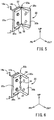
- FIG 2 is a perspective view illustrating in detail a joint portion between the front side member 12 and the radiator support 14 in the vehicle body front structure 10.
- the front side member 12 and the crash box 18 are shown by dashed lines in the figure.
- arrow FR represents the front side of the vehicle
- arrow OUT represents the lateral side (or left side) of the vehicle
- arrow UP represents the upper side of the vehicle (the same applies to FIGS. 4 to 9 ).
- the vehicle body front structure 10 includes a replaceable bracket 20.
- the front side member 12 and the radiator support 14 are coupled via the replaceable bracket 20.
- the replaceable bracket 20 is disposed between the front side member 12 and the radiator support 14 and is secured to the front side member 12 and the radiator support 14.
- the replaceable bracket 20 thus serves as a coupling member that couples the front side member 12 and the radiator support 14.
- the replaceable bracket 20 serves as a support member that supports the radiator support 14 with respect to the front side member 12.
- the replaceable bracket 20 is located between the front side member 12 and the crash box 18 as viewed in plan.
- the replaceable bracket 20 is located forward in the vehicle with respect to at least a part of the front side member 12, and rearward in the vehicle with respect to at least a part of the crash box 18. Therefore, the replaceable bracket 20 is arranged in the longitudinal direction of the vehicle between at least a part of the front side member 12 and at least a part of the crash box 18.
- the front side member 12, the radiator support 14, and the crash box 18 are fastened or coupled together with a fastener such as bolts 25.
- a width extending gusset 22 disposed on the front side member 12, the replaceable bracket 20 attached to the radiator support 14, and the crash box 18 are fastened or coupled together by a fastener such as bolts 24.
- the replaceable bracket 20 may comprise a relatively thin plate material shaped into an L shape as viewed in plan. Accordingly, the replaceable bracket 20 may include a first planar segment 20a and a second planar segment 20b perpendicular to the first planar segment 20a.
- the replaceable bracket 20 may preferably comprise a material that is thinner than at least the components of the radiator support 14 (e.g. the vertical pillar 14a).
- the replaceable bracket 20 preferably has flanges 20c at its upper and lower ends or edges such that each flange projects toward the side of the bracket 20 opposite from that on which the bracket 20 is attached to the front side member 12 and the radiator support 14. The flanges 20c are not shown in FIGS.
- the flanges 20c may give necessary and sufficient strength or rigidity to the replaceable bracket 20, and need not necessarily be included. As shown in FIG 4 , which will be discussed later, the replaceable bracket 20 may have strength reduced purposefully by cutting out a part of each flange 20c.
- the front side member 12 may include a unitary width extending gusset 22 that forms a width extender extending laterally outward in the vehicle.
- the width extending gusset 22 is a part of the front side member 12 which projects laterally outward in the vehicle.
- the width extending gusset 22 has a function to transmit the collision impact on a lateral part of the vehicle front, via the crash box 18, to the front side member 12.
- the width extending gusset 22 may preferably be triangular or dovetail shaped as viewed in plan, with a flat surface 22a parallel to the lateral direction of the vehicle.
- the replaceable bracket 20 is secured to the width extending gusset 22.
- the second planar segment 20b of the replaceable bracket 20 is preferably fastened to the forward facing flat surface 22a of the width extending gusset 22 with a fastener such as the bolts 24.
- the width extending gusset 22, the replaceable bracket 20, and the crash box 18 are preferably fastened together by a fastener such as the bolts 24. With this configuration, the replaceable bracket 20 is detachably secured to the front side member 12.
- the radiator support 14 has a unitary attachment portion 14b on the vehicle lateral side of the vertical pillar 14a in the radiator support 14 such that the attachment portion 14b extends parallel to the longitudinal direction of the vehicle.
- the attachment portion 14b is a part of the vertical pillar 14a which extends laterally outward and then rearward in the vehicle.
- the replaceable bracket 20 is secured to the attachment portion 14b.
- the first planar segment 20a of the replaceable bracket 20 may preferably be fastened to the attachment portion 14b with a fastener such as bolts 26 and nuts 28 such that the replaceable bracket 20 is located laterally outward in the vehicle with respect to the attachment portion 14b. That is, with this configuration, the replaceable bracket 20 is detachably secured to the vertical pillar 14a of the radiator support 14.
- the vehicle body front structure 10 in embodiments includes the replaceable bracket 20 provided as a separate part from the radiator support 14 and detachably secured to the radiator support 14.
- a lateral outer part of the radiator support 14 is provided as the replaceable bracket 20 separate from the vertical pillar 14a (i.e., provided as a separate part).
- the radiator support 14 may preferably comprise the vertical pillar 14a and the replaceable bracket 20 separate from it at the boundary between the (body of the) front side member 12 and the width extending gusset 22, such that the vertical pillar 14a is associated with the (body of the) front side member 12 while the replaceable bracket 20 is associated with the width extending gusset 22.
- FIG 3 is a diagram illustrating effects of the vehicle body front structure 10 of the embodiment configured as described above. Some features such as the bolts 24, 25 are not shown in FIG 3 .
- the front bumper reinforcement 16 is displaced laterally outward and rearward in the vehicle, whereby the shock absorber crash box 18 is deformed.
- a collision impact on a lateral part of the vehicle front is transmitted from the width extending gusset 22 to the front side member 12.
- the replaceable bracket 20 is deformed or fractured by this collision impact on the lateral part of the vehicle front.
- the replaceable bracket 20 is deformed so that the first and second planar segments 20a, 20b are opened, namely, so as to form an obtuse angle therebetween.
- the replaceable bracket 20 is fractured (or broken) until the first and second planar segments 20a, 20b are separated.
- This deformation or fracture of the replaceable bracket 20 reduces transmission of the collision impact to the radiator support 14, thereby effectively minimizing deformation of, or damage to, the vertical pillar 14a or other components of the radiator support 14. That is, in the event of a frontal collision of the vehicle 8, the radiator support 14 can remain intact. As a result, the replaceable bracket 20 need only be replaced in many cases.
- the vehicle body front structure 10 in an embodiment may preferably include brittle portions 30a, 30b in the replaceable bracket 20 so as to facilitate deformation or fracture of the replaceable bracket 20 by the collision impact on the a lateral part of the vehicle front.
- FIG 4 shows the brittle portion 30a
- FIG 6 shows the brittle portion 30b.
- the brittle portions 30a, 30b will be simply referred to as the brittle portions 30 unless they need to be distinguished.
- the brittle portion 30 may be more brittle (i.e.
- the replaceable bracket 20 may be located between the first planar segment 20a, which is secured to the vertical pillar 14a of the radiator support 14, and the second planar segment 20b, which is secured to the width extending gusset 22 on the front side member 12.
- Specific examples of the brittle portion 30 of the replaceable bracket 20 will be described below with reference to FIGS. 4 to 7 . Some features such as the front side member 12, the crash box 18, and the bolts 24 are not shown in FIGS. 4 to 7 .
- FIG 4 is a diagram showing an example of the brittle portion 30 of the replaceable bracket 20, in which a part of each flange 20c is cut out.
- FIG 5 is a diagram illustrating how the replaceable bracket 20 configured as shown in FIG 4 is deformed when a collision impact is applied to a lateral part of the vehicle front. The shape before deformation is shown in dashed lines, and the shape after deformation is shown in solid lines.
- the replaceable bracket 20 has the brittle portion 30a between the first and second planar segments 20a, 20b.
- each flange 20c has a cutout 32 in its substantially middle part, namely between the first and second planar segments 20a, 20b.
- each flange 20c projects in a smaller width at the boundary between the first and second planar segments 20a, 20b than in the remaining portions of the flange 20c.
- each flange 20c may project in zero width in at least a part of the flange 20c.
- FIG 6 is a diagram showing an example of the brittle portion 30 of the replaceable bracket 20, in which a plurality of holes are formed in the replaceable bracket 20.
- FIG 7 is a diagram illustrating how the replaceable bracket 20 configured as shown in FIG 6 is fractured by a collision impact on the lateral part of the vehicle front. The shape before fracture is shown by dashed lines, and the shape after fracture is shown by solid lines. In the configuration shown in FIG 6 , the replaceable bracket 20 has the brittle portion 30b between the first and second planar segments 20a, 20b.
- a plurality of (three in FIG 6 ) holes 34 extends through the thickness of the replaceable bracket 20 in a substantially middle part of the replaceable bracket 20, namely in a part of the replaceable bracket 20 at the boundary between the first and second planar segments 20a, 20b.
- the plurality of holes 34 may preferably be formed at substantially regular intervals in the corner (of the L shape as viewed in plan) at the boundary between the first and second planar segments 20a, 20b.
- a single hole 34 may be formed at the boundary between the first and second planar segments 20a, 20b.
- the replaceable bracket 20 when a collision impact is applied to a lateral part of the vehicle front, the replaceable bracket 20 is more easily fractured such that the first and second planar segments 20a, 20b are separated at the boundary therebetween as shown in FIG 7 due to the brittle portion 30b (or holes 34). Namely, the brittle portion 30b of the replaceable bracket 20 facilitates fracture of the replaceable bracket 20 by a collision impact on the lateral part of the vehicle front.
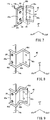
- FIG 8 is a perspective view illustrating the configuration of an alternative replaceable bracket 40 that can be suitably used in the vehicle body front structure 10 in embodiments.
- the replaceable bracket 40 is made from a relatively thin plate material in a similar manner to the replaceable bracket 20, and includes a first planar segment 40a, a second planar segment 40b, and a third planar segment 40c.
- the second planar segment 40b is perpendicular to the first and third planar segments 40a, 40c.
- the first and third planar segments 40a, 40c are parallel to each other.
- the first planar segment 40a extends laterally inward in the vehicle from the second planar segment 40b, while the third planar segment 40c extends laterally outward in the vehicle from the second planar segment 40b.
- the replaceable bracket 40 has flanges 40d at its upper and lower ends such that each flange extends forward and laterally outward in the vehicle.
- the replaceable bracket 40 is attached to the vertical pillar 14a of the radiator support 14 on the front side of the vertical pillar 14a.
- the first planar segment 40a is fastened to a forward surface of the vertical pillar 14a with a fastener such as the bolts 26 and nuts 28.
- the third planar segment 40c is fastened to a forward surface of the width extending gusset 22 on the front side member 12 with a fastener such as the bolts 24.
- the vertical pillar 14a need not have an attachment portion 14b.
- the replaceable bracket 40 is fastened to the vertical pillar 14a on the front side of the vertical pillar 14a, the part of the replaceable bracket 40 which is effective against a collision impact on the lateral part of the vehicle front is situated laterally outward in the vehicle with respect to the vertical pillar 14a. That is, the replaceable bracket 40 is secured to the vertical pillar 14a with its main part located laterally outward in the vehicle with respect to the vertical pillar 14a.
- the vehicle body front structure 10 including the replaceable bracket 40 also provides the effects described above against a collision impact on the lateral part of the vehicle front.
- the replaceable bracket 40 when a collision impact is applied to the lateral part of the vehicle front, the replaceable bracket 40 is deformed such that the first and second planar segments 40a, 40b are more closed, namely such that the first and second planar segments 40a, 40b form an acute angle therebetween.
- the replaceable bracket 40 is fractured or broken such that the first and second planar segments 40a, 40b are separated. This deformation or fracture of the replaceable bracket 40 reduces transmission of the collision impact to the radiator support 14, thereby effectively minimizing deformation of, or damage to, the vertical pillar 14a or other components of the radiator support 14.
- each flange 40d may have a cutout 32 between the first and second planar segments 40a, 40b of the bracket 40.
- a plurality of holes 34 may extend through the thickness of the replaceable bracket 40 in a part of the replaceable bracket 40, at the boundary between the first and second planar segments 40a, 40b.
- a plurality of holes 34 may extend through the thickness of the replaceable bracket 40 in a part of the replaceable bracket 40, at the boundary between the second planar segment 40b and the third planar segment 40c.
- the replaceable bracket 20 is disposed between the shock absorber crash box 18 and the front side member 12.
- the replaceable bracket 20 is a separate part from the radiator support 14 and is detachably secured to the radiator support 14.
- the replaceable bracket 20 is secured to the vertical pillar 14a of the radiator support 14 such that the bracket is located laterally outward in the vehicle with respect to the vertical pillar 14a, and is secured to the front side member 12. Accordingly, in the event of a frontal collision, the front bumper reinforcement 16 is displaced laterally outward and rearward in the vehicle, whereby the crash box 18 is deformed, and the replaceable bracket 20 is deformed or fractured by the collision impact on the lateral part of the vehicle front. This minimizes damage to the radiator support 14. As a result, the replaceable bracket 20 need only be replaced in many cases. Accordingly, the vehicle body front structure 10 that reduces repair cost after a vehicle collision can be provided.
- the replaceable bracket 20 is secured to the vertical pillar 14a of the radiator support 14 by a fastener such as the bolts 26 and nuts 28. This minimizes damage to the radiator support 14 with the practical configuration, thus reducing repair cost after a vehicle collision.
- the replaceable bracket 20 has the brittle portion 30 between that portion of the replaceable bracket 20 which is secured to the vertical pillar 14a of the radiator support 14 and that portion of the replaceable bracket 20 which is secured to the front side member 12. This allows the replaceable bracket 20 to be more efficiently deformed or fractured by a collision impact on the lateral part of the vehicle front, thus more effectively reducing damage to the radiator support 14.
- the front side member 12 includes the unitary width extending gusset 22 serving as the width extender extending laterally outward in the vehicle, and the replaceable bracket 20 is secured to the forward surface of the width extending gusset 22. This minimizes damage to the radiator support 14 with the practical configuration, thus reducing repair cost after a vehicle collision.
Landscapes
- Engineering & Computer Science (AREA)
- Mechanical Engineering (AREA)
- Chemical & Material Sciences (AREA)
- Combustion & Propulsion (AREA)
- Transportation (AREA)
- Body Structure For Vehicles (AREA)
- Cooling, Air Intake And Gas Exhaust, And Fuel Tank Arrangements In Propulsion Units (AREA)
Abstract
Description
- The present invention relates to vehicle body front structures, and more particularly to their improvements with reduced repair cost after a vehicle collision.
- A vehicle body front structure is known which includes front side members, a radiator support, a front bumper reinforcement, and shock absorbers attached to the front bumper reinforcement. Techniques have been proposed for reducing damage to the cooling system in the event of a vehicle collision for such a vehicle body front structure. In an example of these techniques, Patent Document 1 describes a support structure for a vehicle cooling system. In this technique, a radiator support is coupled to the vehicle body through a separate part from the radiator support so that in the event of a vehicle collision the separate part is deformed, thereby effectively minimizing damage to the cooling system.
- Patent Document 1: Japanese Patent Application Publication No.
2005-335668 - In the conventional technique described above, however, when a collision impact is applied to a more lateral part of the vehicle front than the front side member in a vehicle collision, the entire radiator support need be replaced, even if it is a relatively minor collision (e.g. a small overlap crash). This may increase repair cost. The inventors have identified this problem through intensive studies for improving performance of vehicle body front structures.
- The present invention has been developed in view of the above circumstances and aims to provide a vehicle body front structure with reduced repair cost after a vehicle collision.
- In view of the above object, the invention provides, in a first aspect, a vehicle body front structure including a front side member, a radiator support, a front bumper reinforcement, and a shock absorber attached to the front bumper reinforcement, characterized by including: a replaceable bracket disposed between the shock absorber and the front side member, the replaceable bracket being a separate part from the radiator support and being detachably secured to the radiator support, wherein the replaceable bracket is secured to a vertical pillar of the radiator support such that the bracket is located laterally outward in the vehicle with respect to the vertical pillar, and is secured to the front side member.
- In the first aspect of the invention, the vehicle body front structure includes the replaceable bracket disposed between the shock absorber and the front side member, the replaceable bracket being a separate part from the radiator support and being detachably secured to the radiator support, and the replaceable bracket is secured to the vertical pillar of the radiator support such that the bracket is located laterally outward in the vehicle with respect to the vertical pillar, and is secured to the front side member. Accordingly, in the event of a frontal collision, the front bumper reinforcement is displaced laterally outward and rearward in the vehicle, whereby the shock absorber is deformed, and the replaceable bracket is deformed or fractured by the collision impact on a lateral part of the vehicle front. This minimizes damage to the radiator support, and the replaceable bracket need only be replaced in many cases. Accordingly, a vehicle body front structure that reduces repair cost after a vehicle collision can be provided.
- In a second aspect of the invention, which depends from the first aspect of the invention, the replaceable bracket is secured to the vertical pillar of the radiator support by a fastener. This minimizes damage to the radiator support in a practical manner, thus reducing repair cost after a vehicle collision.
- In a third aspect of the invention, which depends from the first or second aspect of the invention, the replaceable bracket has a first portion secured to the vertical pillar of the radiator support, a second portion secured to the front side member, and a brittle portion between the first portion and the second portion. This allows the replaceable bracket to be more efficiently deformed or fractured by a collision impact on a lateral part of the vehicle front, thus more effectively minimizing damage to the radiator support.
- In a fourth aspect of the invention, which depends from any one of the first to third aspects of the invention, the front side member includes a unitary width extender extending laterally outward in the vehicle, and the replaceable bracket is secured to a forward surface of the width extender. This minimizes damage to the radiator support with the practical configuration, thereby reducing repair cost after a vehicle collision.
-
-
FIG 1 is a schematic plan view schematically showing an example configuration of a vehicle body front structure according to a preferred embodiment of the present invention. -
FIG 2 is a perspective view illustrating in detail a joint portion between a front side member and a radiator support in the vehicle body front structure ofFIG 1 . -
FIG 3 is an illustration of effects of the vehicle body front structure ofFIG 1 . -
FIG 4 is a diagram showing an example brittle portion that can be included in the replaceable bracket shown inFIG 1 , in which a part of each flange is cut out. -
FIG 5 is an illustration of effects of the brittle portion shown inFIG 4 . -
FIG 6 is a diagram showing an example brittle portion that can be included in the replaceable bracket inFIG 1 , in which a plurality of holes are formed in the replaceable bracket. -
FIG 7 is an illustration of effects of the brittle portion shown inFIG 6 . -
FIG 8 is a perspective view illustrating the configuration of another replaceable bracket that can be suitably used in the vehicle body front structure shown inFIG 1 . -
FIG 9 is an illustration of effects of the replaceable bracket ofFIG 8 . - The replaceable bracket preferably comprises a relatively thin plate material shaped into an L-shape as viewed in plan. Preferably, the replaceable bracket may include a first planar segment and a second planar segment perpendicular to the first planar segment. Preferably, the replaceable bracket may have flanges at its upper and lower ends that project to the side of the bracket opposite from that on which the bracket is attached to the front side member and the radiator support.
- Preferably, the first planar segment of the replaceable bracket may be secured to a vertical pillar in the radiator support. Preferably, the second planar segment of the replaceable bracket may be secured to the width extender on the front side member.
- The radiator support may preferably comprise a main portion, including the vertical pillar, and the replaceable bracket separate from it at the boundary between the front side member and the width extender. The main portion is associated with the front side member, while the replaceable bracket associated with the width extender.
- The brittle portion is preferably located between the first and second planar segments in the replaceable bracket. Preferably, the brittle portion may comprise a cutout in the flange between the first and second planar segments. Preferably, the brittle portion may comprise a plurality of holes extending through the thickness of the replaceable bracket at the boundary between the first and second planar segments.
- Preferred embodiments of the present invention will be described in detail with reference to the accompanying drawings. Features are not always drawn to scale in the drawings.
-
FIG 1 is a schematic plan view schematically showing an example of the configuration of a vehiclebody front structure 10 according to a preferred embodiment of the present invention. InFIG 1 , arrow FR represents the front side of a vehicle, and arrow OUT represents the lateral side (or left side) of the vehicle (the same applies toFIG 3 ). As shown inFIG 1 , the vehiclebody front structure 10 in the shown embodiment is provided on the front side of avehicle 8, and includes a pair of left and right front side members 12 (only the left one is shown inFIG 1 ), aradiator support 14, and afront bumper reinforcement 16. A pair of left and right crash boxes 18 (only the left one is shown inFIG 1 ) are attached to the rear side of thefront bumper reinforcement 16. In other words, thefront bumper reinforcement 16 is secured at its ends to thecrash boxes 18. - When subjected to an axial compression due to a shock from the front side of the vehicle, the
crash box 18 is crushed, for example, into the form of a bellows. At this time, thecrash box 18 is deformed to absorb shock energy, thereby reducing the shock on structural members of the vehicle such as thefront side member 12. In this embodiment, thecrash box 18 is thus an example of a shock absorber attached to thefront bumper reinforcement 16. -
FIG 2 is a perspective view illustrating in detail a joint portion between thefront side member 12 and the radiator support 14 in the vehiclebody front structure 10. Thefront side member 12 and thecrash box 18 are shown by dashed lines in the figure. InFIG 2 , arrow FR represents the front side of the vehicle, arrow OUT represents the lateral side (or left side) of the vehicle, and arrow UP represents the upper side of the vehicle (the same applies toFIGS. 4 to 9 ). As shown inFIG 2 , the vehiclebody front structure 10 includes areplaceable bracket 20. Thefront side member 12 and theradiator support 14 are coupled via thereplaceable bracket 20. Specifically, thereplaceable bracket 20 is disposed between thefront side member 12 and theradiator support 14 and is secured to thefront side member 12 and theradiator support 14. Thereplaceable bracket 20 thus serves as a coupling member that couples thefront side member 12 and theradiator support 14. In other words, thereplaceable bracket 20 serves as a support member that supports theradiator support 14 with respect to thefront side member 12. - As shown in
FIG 1 , thereplaceable bracket 20 is located between thefront side member 12 and thecrash box 18 as viewed in plan. In other words, thereplaceable bracket 20 is located forward in the vehicle with respect to at least a part of thefront side member 12, and rearward in the vehicle with respect to at least a part of thecrash box 18. Therefore, thereplaceable bracket 20 is arranged in the longitudinal direction of the vehicle between at least a part of thefront side member 12 and at least a part of thecrash box 18. - As shown in
FIG 1 , in the vehiclebody front structure 10, thefront side member 12, theradiator support 14, and thecrash box 18 are fastened or coupled together with a fastener such asbolts 25. As described later, awidth extending gusset 22 disposed on thefront side member 12, thereplaceable bracket 20 attached to theradiator support 14, and thecrash box 18 are fastened or coupled together by a fastener such asbolts 24. Some features such as thebolts 25 are not shown inFIG 2 . - As shown in
FIGS. 1 and 2 , thereplaceable bracket 20 may comprise a relatively thin plate material shaped into an L shape as viewed in plan. Accordingly, thereplaceable bracket 20 may include a firstplanar segment 20a and a secondplanar segment 20b perpendicular to the firstplanar segment 20a. Thereplaceable bracket 20 may preferably comprise a material that is thinner than at least the components of the radiator support 14 (e.g. thevertical pillar 14a). As shown inFIG 2 , thereplaceable bracket 20 preferably hasflanges 20c at its upper and lower ends or edges such that each flange projects toward the side of thebracket 20 opposite from that on which thebracket 20 is attached to thefront side member 12 and theradiator support 14. Theflanges 20c are not shown inFIGS. 1 and3 . Theflanges 20c may give necessary and sufficient strength or rigidity to thereplaceable bracket 20, and need not necessarily be included. As shown inFIG 4 , which will be discussed later, thereplaceable bracket 20 may have strength reduced purposefully by cutting out a part of eachflange 20c. - As shown in
FIGS. 1 and 2 , thefront side member 12 may include a unitarywidth extending gusset 22 that forms a width extender extending laterally outward in the vehicle. In other words, thewidth extending gusset 22 is a part of thefront side member 12 which projects laterally outward in the vehicle. As described later with reference toFIG 3 , thewidth extending gusset 22 has a function to transmit the collision impact on a lateral part of the vehicle front, via thecrash box 18, to thefront side member 12. Thewidth extending gusset 22 may preferably be triangular or dovetail shaped as viewed in plan, with aflat surface 22a parallel to the lateral direction of the vehicle. Thereplaceable bracket 20 is secured to thewidth extending gusset 22. The secondplanar segment 20b of thereplaceable bracket 20 is preferably fastened to the forward facingflat surface 22a of thewidth extending gusset 22 with a fastener such as thebolts 24. Further, as shown inFIG 1 , thewidth extending gusset 22, thereplaceable bracket 20, and thecrash box 18 are preferably fastened together by a fastener such as thebolts 24. With this configuration, thereplaceable bracket 20 is detachably secured to thefront side member 12. - As shown in
FIG 2 , theradiator support 14 has aunitary attachment portion 14b on the vehicle lateral side of thevertical pillar 14a in theradiator support 14 such that theattachment portion 14b extends parallel to the longitudinal direction of the vehicle. In other words, theattachment portion 14b is a part of thevertical pillar 14a which extends laterally outward and then rearward in the vehicle. Thereplaceable bracket 20 is secured to theattachment portion 14b. The firstplanar segment 20a of thereplaceable bracket 20 may preferably be fastened to theattachment portion 14b with a fastener such asbolts 26 andnuts 28 such that thereplaceable bracket 20 is located laterally outward in the vehicle with respect to theattachment portion 14b. That is, with this configuration, thereplaceable bracket 20 is detachably secured to thevertical pillar 14a of theradiator support 14. - As described above, the vehicle
body front structure 10 in embodiments includes thereplaceable bracket 20 provided as a separate part from theradiator support 14 and detachably secured to theradiator support 14. In other words, a lateral outer part of theradiator support 14 is provided as thereplaceable bracket 20 separate from thevertical pillar 14a (i.e., provided as a separate part). As shown inFIG 1 , theradiator support 14 may preferably comprise thevertical pillar 14a and thereplaceable bracket 20 separate from it at the boundary between the (body of the)front side member 12 and thewidth extending gusset 22, such that thevertical pillar 14a is associated with the (body of the)front side member 12 while thereplaceable bracket 20 is associated with thewidth extending gusset 22. -
FIG 3 is a diagram illustrating effects of the vehiclebody front structure 10 of the embodiment configured as described above. Some features such as thebolts FIG 3 . As shown inFIG 3 , in the event of a frontal collision in which a lateral part (near the side end) of the front of thevehicle 8 collides with anobject 6, thefront bumper reinforcement 16 is displaced laterally outward and rearward in the vehicle, whereby the shockabsorber crash box 18 is deformed. A collision impact on a lateral part of the vehicle front is transmitted from thewidth extending gusset 22 to thefront side member 12. At this time, in the vehiclebody front structure 10 of the present embodiment, thereplaceable bracket 20 is deformed or fractured by this collision impact on the lateral part of the vehicle front. Specifically, as shown inFIG 5 , which will be discussed later, thereplaceable bracket 20 is deformed so that the first and secondplanar segments FIG 7 , which will be discussed later, thereplaceable bracket 20 is fractured (or broken) until the first and secondplanar segments replaceable bracket 20 reduces transmission of the collision impact to theradiator support 14, thereby effectively minimizing deformation of, or damage to, thevertical pillar 14a or other components of theradiator support 14. That is, in the event of a frontal collision of thevehicle 8, theradiator support 14 can remain intact. As a result, thereplaceable bracket 20 need only be replaced in many cases. - In order to enhance the above effects, the vehicle
body front structure 10 in an embodiment may preferably includebrittle portions replaceable bracket 20 so as to facilitate deformation or fracture of thereplaceable bracket 20 by the collision impact on the a lateral part of the vehicle front.FIG 4 shows thebrittle portion 30a, andFIG 6 shows thebrittle portion 30b. Hereinafter, thebrittle portions replaceable bracket 20 and may be located between the firstplanar segment 20a, which is secured to thevertical pillar 14a of theradiator support 14, and the secondplanar segment 20b, which is secured to thewidth extending gusset 22 on thefront side member 12. Specific examples of the brittle portion 30 of thereplaceable bracket 20 will be described below with reference toFIGS. 4 to 7 . Some features such as thefront side member 12, thecrash box 18, and thebolts 24 are not shown inFIGS. 4 to 7 . -
FIG 4 is a diagram showing an example of the brittle portion 30 of thereplaceable bracket 20, in which a part of eachflange 20c is cut out.FIG 5 is a diagram illustrating how thereplaceable bracket 20 configured as shown inFIG 4 is deformed when a collision impact is applied to a lateral part of the vehicle front. The shape before deformation is shown in dashed lines, and the shape after deformation is shown in solid lines. In the configuration shown inFIG 4 , thereplaceable bracket 20 has thebrittle portion 30a between the first and secondplanar segments flange 20c has acutout 32 in its substantially middle part, namely between the first and secondplanar segments flange 20c projects in a smaller width at the boundary between the first and secondplanar segments flange 20c. Alternatively, eachflange 20c may project in zero width in at least a part of theflange 20c. In this configuration, when a collision impact is applied to the lateral part of the vehicle front, thereplaceable bracket 20 is more easily deformed so that the first and secondplanar segments FIG 5 due to the brittle portion 30 (or cutouts 32). Namely, thebrittle portion 30a of thereplaceable bracket 20 facilitates deformation of thereplaceable bracket 20 by a collision impact on the lateral part of the vehicle front. -
FIG 6 is a diagram showing an example of the brittle portion 30 of thereplaceable bracket 20, in which a plurality of holes are formed in thereplaceable bracket 20.FIG 7 is a diagram illustrating how thereplaceable bracket 20 configured as shown inFIG 6 is fractured by a collision impact on the lateral part of the vehicle front. The shape before fracture is shown by dashed lines, and the shape after fracture is shown by solid lines. In the configuration shown inFIG 6 , thereplaceable bracket 20 has thebrittle portion 30b between the first and secondplanar segments FIG 6 ) holes 34 extends through the thickness of thereplaceable bracket 20 in a substantially middle part of thereplaceable bracket 20, namely in a part of thereplaceable bracket 20 at the boundary between the first and secondplanar segments holes 34 may preferably be formed at substantially regular intervals in the corner (of the L shape as viewed in plan) at the boundary between the first and secondplanar segments single hole 34 may be formed at the boundary between the first and secondplanar segments replaceable bracket 20 is more easily fractured such that the first and secondplanar segments FIG 7 due to thebrittle portion 30b (or holes 34). Namely, thebrittle portion 30b of thereplaceable bracket 20 facilitates fracture of thereplaceable bracket 20 by a collision impact on the lateral part of the vehicle front. -
FIG 8 is a perspective view illustrating the configuration of an alternativereplaceable bracket 40 that can be suitably used in the vehiclebody front structure 10 in embodiments. Thereplaceable bracket 40 is made from a relatively thin plate material in a similar manner to thereplaceable bracket 20, and includes a firstplanar segment 40a, a secondplanar segment 40b, and a thirdplanar segment 40c. The secondplanar segment 40b is perpendicular to the first and thirdplanar segments planar segments planar segment 40a extends laterally inward in the vehicle from the secondplanar segment 40b, while the thirdplanar segment 40c extends laterally outward in the vehicle from the secondplanar segment 40b. Thereplaceable bracket 40 hasflanges 40d at its upper and lower ends such that each flange extends forward and laterally outward in the vehicle. - The
replaceable bracket 40 is attached to thevertical pillar 14a of theradiator support 14 on the front side of thevertical pillar 14a. Specifically, as shown inFIG 8 , the firstplanar segment 40a is fastened to a forward surface of thevertical pillar 14a with a fastener such as thebolts 26 and nuts 28. The thirdplanar segment 40c is fastened to a forward surface of thewidth extending gusset 22 on thefront side member 12 with a fastener such as thebolts 24. In the configuration shown inFIG 8 , thevertical pillar 14a need not have anattachment portion 14b. Although thereplaceable bracket 40 is fastened to thevertical pillar 14a on the front side of thevertical pillar 14a, the part of thereplaceable bracket 40 which is effective against a collision impact on the lateral part of the vehicle front is situated laterally outward in the vehicle with respect to thevertical pillar 14a. That is, thereplaceable bracket 40 is secured to thevertical pillar 14a with its main part located laterally outward in the vehicle with respect to thevertical pillar 14a. - The vehicle
body front structure 10 including thereplaceable bracket 40 also provides the effects described above against a collision impact on the lateral part of the vehicle front. As shown inFIG 9 , when a collision impact is applied to the lateral part of the vehicle front, thereplaceable bracket 40 is deformed such that the first and secondplanar segments planar segments replaceable bracket 40 is fractured or broken such that the first and secondplanar segments replaceable bracket 40 reduces transmission of the collision impact to theradiator support 14, thereby effectively minimizing deformation of, or damage to, thevertical pillar 14a or other components of theradiator support 14. In order to enhance these effects, a brittle portion 30 may preferably be included into thereplaceable bracket 40. For example, eachflange 40d may have acutout 32 between the first and secondplanar segments bracket 40. Alternatively, a plurality ofholes 34 may extend through the thickness of thereplaceable bracket 40 in a part of thereplaceable bracket 40, at the boundary between the first and secondplanar segments holes 34 may extend through the thickness of thereplaceable bracket 40 in a part of thereplaceable bracket 40, at the boundary between the secondplanar segment 40b and the thirdplanar segment 40c. - In the embodiments described above, the
replaceable bracket 20 is disposed between the shockabsorber crash box 18 and thefront side member 12. Thereplaceable bracket 20 is a separate part from theradiator support 14 and is detachably secured to theradiator support 14. Thereplaceable bracket 20 is secured to thevertical pillar 14a of theradiator support 14 such that the bracket is located laterally outward in the vehicle with respect to thevertical pillar 14a, and is secured to thefront side member 12. Accordingly, in the event of a frontal collision, thefront bumper reinforcement 16 is displaced laterally outward and rearward in the vehicle, whereby thecrash box 18 is deformed, and thereplaceable bracket 20 is deformed or fractured by the collision impact on the lateral part of the vehicle front. This minimizes damage to theradiator support 14. As a result, thereplaceable bracket 20 need only be replaced in many cases. Accordingly, the vehiclebody front structure 10 that reduces repair cost after a vehicle collision can be provided. - The
replaceable bracket 20 is secured to thevertical pillar 14a of theradiator support 14 by a fastener such as thebolts 26 and nuts 28. This minimizes damage to theradiator support 14 with the practical configuration, thus reducing repair cost after a vehicle collision. - The
replaceable bracket 20 has the brittle portion 30 between that portion of thereplaceable bracket 20 which is secured to thevertical pillar 14a of theradiator support 14 and that portion of thereplaceable bracket 20 which is secured to thefront side member 12. This allows thereplaceable bracket 20 to be more efficiently deformed or fractured by a collision impact on the lateral part of the vehicle front, thus more effectively reducing damage to theradiator support 14. - The
front side member 12 includes the unitarywidth extending gusset 22 serving as the width extender extending laterally outward in the vehicle, and thereplaceable bracket 20 is secured to the forward surface of thewidth extending gusset 22. This minimizes damage to theradiator support 14 with the practical configuration, thus reducing repair cost after a vehicle collision. - While preferred embodiments of the present invention have been described in detail above with reference to the drawings, the present invention is not limited to those embodiments and can be embodied in various modified forms without departing from the spirit and scope of the invention.
- 10: Vehicle body front structure, 12: Front side member, 14: Radiator support, 14a: Vertical pillar, 16: Front bumper reinforcement, 18: Crash box (Shock absorber), 20, 40: Replaceable bracket, 22: Width extending gusset (Width extender), 26: Bolt (Fastener), 28: Nut (Fastener), 30: Brittle portion
Claims (4)
- A vehicle body front structure comprising a front side member, a radiator support, a front bumper reinforcement, and a shock absorber attached to the front bumper reinforcement, characterized by further comprising:a replaceable bracket disposed between the shock absorber and the front side member, the replaceable bracket being a separate part from the radiator support and being detachably secured to the radiator support, whereinthe replaceable bracket is secured to a vertical pillar of the radiator support such that the bracket is located laterally outward in the vehicle with respect to the vertical pillar, and is secured to the front side member.
- The vehicle body front structure according to claim 1, wherein
the replaceable bracket is secured to the vertical pillar of the radiator support by a fastener. - The vehicle body front structure according to claim 1 or 2, wherein
the replaceable bracket comprises a first portion secured to the vertical pillar of the radiator support, a second portion_secured to the front side member, and a brittle portion between the first portion and the second portion of the replaceable bracket. - The vehicle body front structure according to any one of claims 1 to 3, wherein
the front side member includes a unitary width extender extending laterally outward in the vehicle, and
the replaceable bracket is secured to a forward surface of the width extended.
Applications Claiming Priority (2)
| Application Number | Priority Date | Filing Date | Title |
|---|---|---|---|
| JP2014242274A JP6186341B2 (en) | 2014-11-28 | 2014-11-28 | Body front structure |
| PCT/JP2015/082963 WO2016084814A2 (en) | 2014-11-28 | 2015-11-24 | Structure for front of vehicle body |
Publications (2)
| Publication Number | Publication Date |
|---|---|
| EP3225512A2 true EP3225512A2 (en) | 2017-10-04 |
| EP3225512A4 EP3225512A4 (en) | 2018-05-23 |
Family
ID=56075104
Family Applications (1)
| Application Number | Title | Priority Date | Filing Date |
|---|---|---|---|
| EP15864233.0A Withdrawn EP3225512A4 (en) | 2014-11-28 | 2015-11-24 | Structure for front of vehicle body |
Country Status (4)
| Country | Link |
|---|---|
| US (1) | US20180244225A1 (en) |
| EP (1) | EP3225512A4 (en) |
| JP (1) | JP6186341B2 (en) |
| WO (1) | WO2016084814A2 (en) |
Cited By (2)
| Publication number | Priority date | Publication date | Assignee | Title |
|---|---|---|---|---|
| WO2019192391A1 (en) * | 2018-04-03 | 2019-10-10 | 上汽通用五菱汽车股份有限公司 | Anti-collision beam connecting assembly |
| US20230101269A1 (en) * | 2021-09-29 | 2023-03-30 | Volvo Car Corporation | Cooling module support bracket |
Families Citing this family (10)
| Publication number | Priority date | Publication date | Assignee | Title |
|---|---|---|---|---|
| US11639039B1 (en) | 2016-02-04 | 2023-05-02 | Maurice Paperi | Matching pieces and kits for repairing broken structures and related methods |
| JP6555221B2 (en) * | 2016-10-14 | 2019-08-07 | トヨタ自動車株式会社 | Bumper reinforcement and side member connection structure |
| US11148578B2 (en) | 2018-03-25 | 2021-10-19 | Maurice Paperi | Universal mounting tabs and kits for automotive components |
| JP6703559B2 (en) * | 2018-03-29 | 2020-06-03 | 株式会社Subaru | Front body structure of vehicle |
| JP6581686B1 (en) * | 2018-03-30 | 2019-09-25 | 株式会社Uacj | Bumper structure |
| JP7006470B2 (en) * | 2018-04-11 | 2022-01-24 | トヨタ自動車株式会社 | Vehicle front structure |
| EP3786000B1 (en) * | 2019-08-26 | 2025-12-24 | Volvo Car Corporation | A connection device for connecting a vehicle crash absorbing member to a vehicle body component |
| HUE073297T2 (en) * | 2020-04-20 | 2026-01-28 | Arcelormittal | Structural node for a motor vehicle front lower load path, and process for assembling said structural node |
| DE102021106754B3 (en) | 2021-03-19 | 2022-02-03 | Dr. Ing. H.C. F. Porsche Aktiengesellschaft | repair procedures |
| JP7448503B2 (en) * | 2021-04-01 | 2024-03-12 | トヨタ自動車株式会社 | vehicle |
Family Cites Families (5)
| Publication number | Priority date | Publication date | Assignee | Title |
|---|---|---|---|---|
| DE102004014073B4 (en) * | 2004-03-23 | 2008-09-25 | Hbpo Gmbh | Frontend with mounting bracket |
| JP4742767B2 (en) * | 2005-09-14 | 2011-08-10 | トヨタ自動車株式会社 | Car body front structure and method of assembling the same |
| US20070076523A1 (en) * | 2005-09-17 | 2007-04-05 | Dirk Yerian | Blender blades for reducing plate out |
| JP4945324B2 (en) * | 2007-05-31 | 2012-06-06 | 本田技研工業株式会社 | Body front structure |
| JP5308926B2 (en) * | 2009-06-10 | 2013-10-09 | 豊田鉄工株式会社 | Support structure for vehicle cooling unit |
-
2014
- 2014-11-28 JP JP2014242274A patent/JP6186341B2/en not_active Expired - Fee Related
-
2015
- 2015-11-24 WO PCT/JP2015/082963 patent/WO2016084814A2/en not_active Ceased
- 2015-11-24 EP EP15864233.0A patent/EP3225512A4/en not_active Withdrawn
- 2015-11-24 US US15/531,615 patent/US20180244225A1/en not_active Abandoned
Cited By (4)
| Publication number | Priority date | Publication date | Assignee | Title |
|---|---|---|---|---|
| WO2019192391A1 (en) * | 2018-04-03 | 2019-10-10 | 上汽通用五菱汽车股份有限公司 | Anti-collision beam connecting assembly |
| US20230101269A1 (en) * | 2021-09-29 | 2023-03-30 | Volvo Car Corporation | Cooling module support bracket |
| EP4159511A1 (en) * | 2021-09-29 | 2023-04-05 | Volvo Car Corporation | Cooling module support bracket |
| US12296888B2 (en) * | 2021-09-29 | 2025-05-13 | Volvo Car Corporation | Cooling module support bracket |
Also Published As
| Publication number | Publication date |
|---|---|
| US20180244225A1 (en) | 2018-08-30 |
| WO2016084814A2 (en) | 2016-06-02 |
| WO2016084814A3 (en) | 2016-08-04 |
| JP2016101890A (en) | 2016-06-02 |
| JP6186341B2 (en) | 2017-08-23 |
| EP3225512A4 (en) | 2018-05-23 |
Similar Documents
| Publication | Publication Date | Title |
|---|---|---|
| EP3225512A2 (en) | Structure for front of vehicle body | |
| US10604092B2 (en) | Bumper beam structure | |
| US9527463B2 (en) | Bumper assemblies including spacer members and vehicles incorporating the same | |
| US9855970B2 (en) | Vehicle front structure | |
| US9371093B1 (en) | Vehicles having upper side member reinforcement portions | |
| US8844986B2 (en) | Vehicle bumper apparatus and crush box thereof | |
| US9527464B2 (en) | Bumpers including a reinforcement bracket and vehicles incorporating the same | |
| US8905466B2 (en) | Structure for front of vehicle body | |
| US9315167B1 (en) | Bumpers including a reinforcement bracket and vehicles incorporating the same | |
| US9493188B2 (en) | Vehicle lower portion structure | |
| CN107107848B (en) | Shock Absorber Systems for Vehicles | |
| US7954863B2 (en) | Bumper beam for a vehicle | |
| CN106573651A (en) | Motor vehicle body arrangement designed in particular for a collision with little overlap | |
| EP2572941B1 (en) | Crush box and vehicle bumper apparatus including the same | |
| EP2894083B1 (en) | Vehicle lower portion structure | |
| US10464609B2 (en) | Small overlap impact countermeasure for vehicle | |
| US9688315B2 (en) | Vehicle and a cradle assembly for the vehicle | |
| JP2007261523A (en) | Automotive bumper equipment | |
| US10421494B2 (en) | Deflector rail for frame rail | |
| RU2487811C1 (en) | Vehicle body | |
| CN107635857B (en) | Subframe method and arrangement for releasing front section of subframe | |
| JP6566018B2 (en) | Vehicle shock absorption structure | |
| CN105873808A (en) | Motor vehicle body with a deformation element and a side member |
Legal Events
| Date | Code | Title | Description |
|---|---|---|---|
| PUAI | Public reference made under article 153(3) epc to a published international application that has entered the european phase |
Free format text: ORIGINAL CODE: 0009012 |
|
| 17P | Request for examination filed |
Effective date: 20170620 |
|
| AK | Designated contracting states |
Kind code of ref document: A2 Designated state(s): AL AT BE BG CH CY CZ DE DK EE ES FI FR GB GR HR HU IE IS IT LI LT LU LV MC MK MT NL NO PL PT RO RS SE SI SK SM TR |
|
| AX | Request for extension of the european patent |
Extension state: BA ME |
|
| DAV | Request for validation of the european patent (deleted) | ||
| DAX | Request for extension of the european patent (deleted) | ||
| A4 | Supplementary search report drawn up and despatched |
Effective date: 20180423 |
|
| RIC1 | Information provided on ipc code assigned before grant |
Ipc: B60K 11/04 20060101ALI20180417BHEP Ipc: B60R 19/34 20060101ALI20180417BHEP Ipc: B60R 19/24 20060101ALI20180417BHEP Ipc: B62D 25/08 20060101AFI20180417BHEP |
|
| STAA | Information on the status of an ep patent application or granted ep patent |
Free format text: STATUS: THE APPLICATION HAS BEEN WITHDRAWN |
|
| 18W | Application withdrawn |
Effective date: 20180928 |