EP3225391A1 - Method for forming crimped parts on continuous body of web member having fiber bundles, and formation device - Google Patents
Method for forming crimped parts on continuous body of web member having fiber bundles, and formation device Download PDFInfo
- Publication number
- EP3225391A1 EP3225391A1 EP14906959.3A EP14906959A EP3225391A1 EP 3225391 A1 EP3225391 A1 EP 3225391A1 EP 14906959 A EP14906959 A EP 14906959A EP 3225391 A1 EP3225391 A1 EP 3225391A1
- Authority
- EP
- European Patent Office
- Prior art keywords
- compression
- bonding
- bonding apparatus
- stage
- rotation
- Prior art date
- Legal status (The legal status is an assumption and is not a legal conclusion. Google has not performed a legal analysis and makes no representation as to the accuracy of the status listed.)
- Granted
Links
- 239000000835 fiber Substances 0.000 title claims abstract description 139
- 238000000034 method Methods 0.000 title claims abstract description 59
- 230000015572 biosynthetic process Effects 0.000 title claims abstract description 46
- 230000002093 peripheral effect Effects 0.000 claims abstract description 62
- 238000007906 compression Methods 0.000 claims description 44
- 238000003825 pressing Methods 0.000 claims description 39
- 238000011144 upstream manufacturing Methods 0.000 claims description 28
- 230000006835 compression Effects 0.000 claims description 21
- 238000004804 winding Methods 0.000 claims description 8
- 238000003466 welding Methods 0.000 description 51
- 238000005304 joining Methods 0.000 description 30
- 239000000463 material Substances 0.000 description 29
- 238000004140 cleaning Methods 0.000 description 22
- 238000007789 sealing Methods 0.000 description 16
- 238000009826 distribution Methods 0.000 description 12
- 239000004698 Polyethylene Substances 0.000 description 11
- 229920000573 polyethylene Polymers 0.000 description 11
- 230000005540 biological transmission Effects 0.000 description 9
- 230000000694 effects Effects 0.000 description 9
- 230000002411 adverse Effects 0.000 description 8
- 102220427212 c.125C>G Human genes 0.000 description 8
- 229920000139 polyethylene terephthalate Polymers 0.000 description 8
- 239000005020 polyethylene terephthalate Substances 0.000 description 8
- 238000010438 heat treatment Methods 0.000 description 7
- 239000004745 nonwoven fabric Substances 0.000 description 7
- 239000004743 Polypropylene Substances 0.000 description 6
- 239000002131 composite material Substances 0.000 description 6
- 229920001155 polypropylene Polymers 0.000 description 6
- 230000000452 restraining effect Effects 0.000 description 5
- 238000004519 manufacturing process Methods 0.000 description 4
- 239000011800 void material Substances 0.000 description 4
- 238000005452 bending Methods 0.000 description 3
- 238000010586 diagram Methods 0.000 description 3
- -1 polyethylene terephthalate Polymers 0.000 description 3
- 102220012720 rs397516289 Human genes 0.000 description 3
- 102220075804 rs796053434 Human genes 0.000 description 3
- 229920001169 thermoplastic Polymers 0.000 description 3
- 239000004416 thermosoftening plastic Substances 0.000 description 3
- 230000033228 biological regulation Effects 0.000 description 2
- 238000005520 cutting process Methods 0.000 description 2
- 238000002474 experimental method Methods 0.000 description 2
- 239000012530 fluid Substances 0.000 description 2
- 230000020169 heat generation Effects 0.000 description 2
- 238000003780 insertion Methods 0.000 description 2
- 230000037431 insertion Effects 0.000 description 2
- 230000007246 mechanism Effects 0.000 description 2
- 238000002844 melting Methods 0.000 description 2
- 230000008018 melting Effects 0.000 description 2
- 230000008844 regulatory mechanism Effects 0.000 description 2
- 230000001360 synchronised effect Effects 0.000 description 2
- 230000032258 transport Effects 0.000 description 2
- 230000000994 depressogenic effect Effects 0.000 description 1
- 238000007730 finishing process Methods 0.000 description 1
- 239000010720 hydraulic oil Substances 0.000 description 1
- 238000012986 modification Methods 0.000 description 1
- 230000004048 modification Effects 0.000 description 1
- 229920005989 resin Polymers 0.000 description 1
- 239000011347 resin Substances 0.000 description 1
- 238000000926 separation method Methods 0.000 description 1
- 238000010008 shearing Methods 0.000 description 1
- 229920005992 thermoplastic resin Polymers 0.000 description 1
- 239000002759 woven fabric Substances 0.000 description 1
Images




Classifications
-
- D—TEXTILES; PAPER
- D06—TREATMENT OF TEXTILES OR THE LIKE; LAUNDERING; FLEXIBLE MATERIALS NOT OTHERWISE PROVIDED FOR
- D06C—FINISHING, DRESSING, TENTERING OR STRETCHING TEXTILE FABRICS
- D06C15/00—Calendering, pressing, ironing, glossing or glazing textile fabrics
- D06C15/02—Calendering, pressing, ironing, glossing or glazing textile fabrics between co-operating press or calender rolls
-
- A—HUMAN NECESSITIES
- A47—FURNITURE; DOMESTIC ARTICLES OR APPLIANCES; COFFEE MILLS; SPICE MILLS; SUCTION CLEANERS IN GENERAL
- A47L—DOMESTIC WASHING OR CLEANING; SUCTION CLEANERS IN GENERAL
- A47L13/00—Implements for cleaning floors, carpets, furniture, walls, or wall coverings
- A47L13/10—Scrubbing; Scouring; Cleaning; Polishing
- A47L13/38—Other dusting implements
-
- A—HUMAN NECESSITIES
- A47—FURNITURE; DOMESTIC ARTICLES OR APPLIANCES; COFFEE MILLS; SPICE MILLS; SUCTION CLEANERS IN GENERAL
- A47L—DOMESTIC WASHING OR CLEANING; SUCTION CLEANERS IN GENERAL
- A47L13/00—Implements for cleaning floors, carpets, furniture, walls, or wall coverings
- A47L13/10—Scrubbing; Scouring; Cleaning; Polishing
- A47L13/16—Cloths; Pads; Sponges
-
- A—HUMAN NECESSITIES
- A47—FURNITURE; DOMESTIC ARTICLES OR APPLIANCES; COFFEE MILLS; SPICE MILLS; SUCTION CLEANERS IN GENERAL
- A47L—DOMESTIC WASHING OR CLEANING; SUCTION CLEANERS IN GENERAL
- A47L13/00—Implements for cleaning floors, carpets, furniture, walls, or wall coverings
- A47L13/10—Scrubbing; Scouring; Cleaning; Polishing
- A47L13/20—Mops
-
- A—HUMAN NECESSITIES
- A47—FURNITURE; DOMESTIC ARTICLES OR APPLIANCES; COFFEE MILLS; SPICE MILLS; SUCTION CLEANERS IN GENERAL
- A47L—DOMESTIC WASHING OR CLEANING; SUCTION CLEANERS IN GENERAL
- A47L13/00—Implements for cleaning floors, carpets, furniture, walls, or wall coverings
- A47L13/10—Scrubbing; Scouring; Cleaning; Polishing
- A47L13/42—Details
- A47L13/46—Securing scouring or polishing cloths or sponges to the handles by gripping means, tongs, or the like
-
- B—PERFORMING OPERATIONS; TRANSPORTING
- B29—WORKING OF PLASTICS; WORKING OF SUBSTANCES IN A PLASTIC STATE IN GENERAL
- B29C—SHAPING OR JOINING OF PLASTICS; SHAPING OF MATERIAL IN A PLASTIC STATE, NOT OTHERWISE PROVIDED FOR; AFTER-TREATMENT OF THE SHAPED PRODUCTS, e.g. REPAIRING
- B29C66/00—General aspects of processes or apparatus for joining preformed parts
- B29C66/80—General aspects of machine operations or constructions and parts thereof
- B29C66/81—General aspects of the pressing elements, i.e. the elements applying pressure on the parts to be joined in the area to be joined, e.g. the welding jaws or clamps
- B29C66/814—General aspects of the pressing elements, i.e. the elements applying pressure on the parts to be joined in the area to be joined, e.g. the welding jaws or clamps characterised by the design of the pressing elements, e.g. of the welding jaws or clamps
- B29C66/8145—General aspects of the pressing elements, i.e. the elements applying pressure on the parts to be joined in the area to be joined, e.g. the welding jaws or clamps characterised by the design of the pressing elements, e.g. of the welding jaws or clamps characterised by the constructional aspects of the pressing elements, e.g. of the welding jaws or clamps
- B29C66/81463—General aspects of the pressing elements, i.e. the elements applying pressure on the parts to be joined in the area to be joined, e.g. the welding jaws or clamps characterised by the design of the pressing elements, e.g. of the welding jaws or clamps characterised by the constructional aspects of the pressing elements, e.g. of the welding jaws or clamps comprising a plurality of single pressing elements, e.g. a plurality of sonotrodes, or comprising a plurality of single counter-pressing elements, e.g. a plurality of anvils, said plurality of said single elements being suitable for making a single joint
-
- B—PERFORMING OPERATIONS; TRANSPORTING
- B29—WORKING OF PLASTICS; WORKING OF SUBSTANCES IN A PLASTIC STATE IN GENERAL
- B29C—SHAPING OR JOINING OF PLASTICS; SHAPING OF MATERIAL IN A PLASTIC STATE, NOT OTHERWISE PROVIDED FOR; AFTER-TREATMENT OF THE SHAPED PRODUCTS, e.g. REPAIRING
- B29C66/00—General aspects of processes or apparatus for joining preformed parts
- B29C66/80—General aspects of machine operations or constructions and parts thereof
- B29C66/83—General aspects of machine operations or constructions and parts thereof characterised by the movement of the joining or pressing tools
- B29C66/834—General aspects of machine operations or constructions and parts thereof characterised by the movement of the joining or pressing tools moving with the parts to be joined
- B29C66/8341—Roller, cylinder or drum types; Band or belt types; Ball types
- B29C66/83411—Roller, cylinder or drum types
- B29C66/83413—Roller, cylinder or drum types cooperating rollers, cylinders or drums
-
- B—PERFORMING OPERATIONS; TRANSPORTING
- B32—LAYERED PRODUCTS
- B32B—LAYERED PRODUCTS, i.e. PRODUCTS BUILT-UP OF STRATA OF FLAT OR NON-FLAT, e.g. CELLULAR OR HONEYCOMB, FORM
- B32B37/00—Methods or apparatus for laminating, e.g. by curing or by ultrasonic bonding
- B32B37/0076—Methods or apparatus for laminating, e.g. by curing or by ultrasonic bonding characterised in that the layers are not bonded on the totality of their surfaces
-
- B—PERFORMING OPERATIONS; TRANSPORTING
- B32—LAYERED PRODUCTS
- B32B—LAYERED PRODUCTS, i.e. PRODUCTS BUILT-UP OF STRATA OF FLAT OR NON-FLAT, e.g. CELLULAR OR HONEYCOMB, FORM
- B32B37/00—Methods or apparatus for laminating, e.g. by curing or by ultrasonic bonding
- B32B37/10—Methods or apparatus for laminating, e.g. by curing or by ultrasonic bonding characterised by the pressing technique, e.g. using action of vacuum or fluid pressure
-
- B—PERFORMING OPERATIONS; TRANSPORTING
- B32—LAYERED PRODUCTS
- B32B—LAYERED PRODUCTS, i.e. PRODUCTS BUILT-UP OF STRATA OF FLAT OR NON-FLAT, e.g. CELLULAR OR HONEYCOMB, FORM
- B32B5/00—Layered products characterised by the non- homogeneity or physical structure, i.e. comprising a fibrous, filamentary, particulate or foam layer; Layered products characterised by having a layer differing constitutionally or physically in different parts
- B32B5/02—Layered products characterised by the non- homogeneity or physical structure, i.e. comprising a fibrous, filamentary, particulate or foam layer; Layered products characterised by having a layer differing constitutionally or physically in different parts characterised by structural features of a fibrous or filamentary layer
- B32B5/022—Non-woven fabric
-
- B—PERFORMING OPERATIONS; TRANSPORTING
- B32—LAYERED PRODUCTS
- B32B—LAYERED PRODUCTS, i.e. PRODUCTS BUILT-UP OF STRATA OF FLAT OR NON-FLAT, e.g. CELLULAR OR HONEYCOMB, FORM
- B32B5/00—Layered products characterised by the non- homogeneity or physical structure, i.e. comprising a fibrous, filamentary, particulate or foam layer; Layered products characterised by having a layer differing constitutionally or physically in different parts
- B32B5/22—Layered products characterised by the non- homogeneity or physical structure, i.e. comprising a fibrous, filamentary, particulate or foam layer; Layered products characterised by having a layer differing constitutionally or physically in different parts characterised by the presence of two or more layers which are next to each other and are fibrous, filamentary, formed of particles or foamed
- B32B5/24—Layered products characterised by the non- homogeneity or physical structure, i.e. comprising a fibrous, filamentary, particulate or foam layer; Layered products characterised by having a layer differing constitutionally or physically in different parts characterised by the presence of two or more layers which are next to each other and are fibrous, filamentary, formed of particles or foamed one layer being a fibrous or filamentary layer
- B32B5/26—Layered products characterised by the non- homogeneity or physical structure, i.e. comprising a fibrous, filamentary, particulate or foam layer; Layered products characterised by having a layer differing constitutionally or physically in different parts characterised by the presence of two or more layers which are next to each other and are fibrous, filamentary, formed of particles or foamed one layer being a fibrous or filamentary layer another layer next to it also being fibrous or filamentary
-
- D—TEXTILES; PAPER
- D04—BRAIDING; LACE-MAKING; KNITTING; TRIMMINGS; NON-WOVEN FABRICS
- D04H—MAKING TEXTILE FABRICS, e.g. FROM FIBRES OR FILAMENTARY MATERIAL; FABRICS MADE BY SUCH PROCESSES OR APPARATUS, e.g. FELTS, NON-WOVEN FABRICS; COTTON-WOOL; WADDING ; NON-WOVEN FABRICS FROM STAPLE FIBRES, FILAMENTS OR YARNS, BONDED WITH AT LEAST ONE WEB-LIKE MATERIAL DURING THEIR CONSOLIDATION
- D04H3/00—Non-woven fabrics formed wholly or mainly of yarns or like filamentary material of substantial length
- D04H3/005—Synthetic yarns or filaments
-
- D—TEXTILES; PAPER
- D04—BRAIDING; LACE-MAKING; KNITTING; TRIMMINGS; NON-WOVEN FABRICS
- D04H—MAKING TEXTILE FABRICS, e.g. FROM FIBRES OR FILAMENTARY MATERIAL; FABRICS MADE BY SUCH PROCESSES OR APPARATUS, e.g. FELTS, NON-WOVEN FABRICS; COTTON-WOOL; WADDING ; NON-WOVEN FABRICS FROM STAPLE FIBRES, FILAMENTS OR YARNS, BONDED WITH AT LEAST ONE WEB-LIKE MATERIAL DURING THEIR CONSOLIDATION
- D04H3/00—Non-woven fabrics formed wholly or mainly of yarns or like filamentary material of substantial length
- D04H3/08—Non-woven fabrics formed wholly or mainly of yarns or like filamentary material of substantial length characterised by the method of strengthening or consolidating
- D04H3/14—Non-woven fabrics formed wholly or mainly of yarns or like filamentary material of substantial length characterised by the method of strengthening or consolidating with bonds between thermoplastic yarns or filaments produced by welding
-
- D—TEXTILES; PAPER
- D06—TREATMENT OF TEXTILES OR THE LIKE; LAUNDERING; FLEXIBLE MATERIALS NOT OTHERWISE PROVIDED FOR
- D06C—FINISHING, DRESSING, TENTERING OR STRETCHING TEXTILE FABRICS
- D06C23/00—Making patterns or designs on fabrics
- D06C23/04—Making patterns or designs on fabrics by shrinking, embossing, moiréing, or crêping
-
- A—HUMAN NECESSITIES
- A47—FURNITURE; DOMESTIC ARTICLES OR APPLIANCES; COFFEE MILLS; SPICE MILLS; SUCTION CLEANERS IN GENERAL
- A47L—DOMESTIC WASHING OR CLEANING; SUCTION CLEANERS IN GENERAL
- A47L13/00—Implements for cleaning floors, carpets, furniture, walls, or wall coverings
- A47L13/10—Scrubbing; Scouring; Cleaning; Polishing
- A47L13/42—Details
-
- B—PERFORMING OPERATIONS; TRANSPORTING
- B32—LAYERED PRODUCTS
- B32B—LAYERED PRODUCTS, i.e. PRODUCTS BUILT-UP OF STRATA OF FLAT OR NON-FLAT, e.g. CELLULAR OR HONEYCOMB, FORM
- B32B2250/00—Layers arrangement
- B32B2250/20—All layers being fibrous or filamentary
-
- B—PERFORMING OPERATIONS; TRANSPORTING
- B32—LAYERED PRODUCTS
- B32B—LAYERED PRODUCTS, i.e. PRODUCTS BUILT-UP OF STRATA OF FLAT OR NON-FLAT, e.g. CELLULAR OR HONEYCOMB, FORM
- B32B2432/00—Cleaning articles, e.g. mops or wipes
-
- B—PERFORMING OPERATIONS; TRANSPORTING
- B32—LAYERED PRODUCTS
- B32B—LAYERED PRODUCTS, i.e. PRODUCTS BUILT-UP OF STRATA OF FLAT OR NON-FLAT, e.g. CELLULAR OR HONEYCOMB, FORM
- B32B5/00—Layered products characterised by the non- homogeneity or physical structure, i.e. comprising a fibrous, filamentary, particulate or foam layer; Layered products characterised by having a layer differing constitutionally or physically in different parts
- B32B5/02—Layered products characterised by the non- homogeneity or physical structure, i.e. comprising a fibrous, filamentary, particulate or foam layer; Layered products characterised by having a layer differing constitutionally or physically in different parts characterised by structural features of a fibrous or filamentary layer
-
- D—TEXTILES; PAPER
- D04—BRAIDING; LACE-MAKING; KNITTING; TRIMMINGS; NON-WOVEN FABRICS
- D04H—MAKING TEXTILE FABRICS, e.g. FROM FIBRES OR FILAMENTARY MATERIAL; FABRICS MADE BY SUCH PROCESSES OR APPARATUS, e.g. FELTS, NON-WOVEN FABRICS; COTTON-WOOL; WADDING ; NON-WOVEN FABRICS FROM STAPLE FIBRES, FILAMENTS OR YARNS, BONDED WITH AT LEAST ONE WEB-LIKE MATERIAL DURING THEIR CONSOLIDATION
- D04H3/00—Non-woven fabrics formed wholly or mainly of yarns or like filamentary material of substantial length
- D04H3/08—Non-woven fabrics formed wholly or mainly of yarns or like filamentary material of substantial length characterised by the method of strengthening or consolidating
Definitions
- the present invention relates to a method and an apparatus for forming a compression-bonding portion in a continuous body of a web member with a fiber bundle such as a tow, which is used to manufacture a cleaning web member.
- Patent Literature 1 a cleaning web member that includes a fiber bundle such as a tow used for cleaning.
- a compression-bonding portion is formed in the web member.
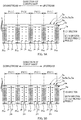
- Fig. 1 is a schematic explanatory view of a first reference example illustrating a process to form a compression-bonding portion jm'.
- Fiber bundles of a web member when being sent in this process are in a state of being continuous in a predetermined direction while the fiber direction is set along the predetermined direction. Therefore, the web member is also in a state of being a continuous body 1a' that is continuous in the predetermined direction.
- the compression-bonding portions jm' are formed at intervals each corresponding to a product pitch in the direction of conveyance.
- the compression-bonding portions jm' are formed, for example, in two stages. That is, for example, a first compression-bonding apparatus 41' and a second compression-bonding apparatus 42' are disposed at two positions in a direction of rotation Dc21' of a rotating drum 21' which is configured to convey the continuous body 1a' of the web member while holding it on an outer peripheral surface 21a'.
- the second compression-bonding apparatus 42' further compresses the compression-bonding portion jm1' of the first stage in cooperation with the supporting portion 21s' on the outer peripheral surface 21a' of the rotating drum 21', to form a compression-bonding portion jm2' of a second stage. Consequently, the compression-bonding portion jm' is formed in the continuous body 1a' of the web member in two stages.
- a compression process performed for the compression-bonding portion jm1' of the first stage by the second compression-bonding apparatus 42' may adversely affect the process of forming the compression-bonding portion jm1' of the first stage, which is performed by the first compression-bonding apparatus 41' positioned upstream in the direction of rotation Dc21'.
- a tensile force F may be generated along the direction of conveyance in the continuous body 1a' of the web member.
- Such tensile force F may be transmitted to the upstream side in the direction of rotation Dc21' in each fiber of the fiber bundle. This may result in disturbance of a fiber distribution of the fiber bundle.
- An aspect of the present disclosure is to restrain negative effects caused by a compression process of a compression-bonding portion of a first stage performed by a second compression-bonding apparatus, from being exerted on a formation process of the compression-bonding portion of the first stage performed by a first compression-bonding apparatus positioned upstream in a direction of rotation.
- An aspect of the present disclosure to achieve an aspect described above is a method for forming compression-bonding portions in a continuous body of a web member including a fiber bundle, while conveying the continuous body in a predetermined direction set as a direction of conveyance, the fiber bundle being continuous in the predetermined direction while a fiber direction is set along the predetermined direction, the compression-bonding portions being formed at intervals in the direction of conveyance, the method comprising: rotating a rotator around a rotation axis along a CD direction intersecting with the direction of conveyance, while holding the continuous body of the web member on an outer peripheral surface of the rotator, to convey the continuous body of the web member in a direction of rotation of the rotator set as the direction of conveyance; compressing a formation target part of each of the compression-bonding portions in the continuous body of the web member, using a first compression-bonding apparatus and the rotator, when the formation target part passes through a position of the first compression-bonding apparatus disposed at a predetermined position in the direction of rotation,
- adverse effects caused by a compression process of a compression-bonding portion of a first stage performed by a second compression-bonding apparatus can be restrained from being exerted on a formation process of the compression-bonding portion of the first stage performed by a first compression-bonding apparatus positioned upstream in a direction of rotation.
- this tensile force in each fiber is hardly transmitted up to the position of the first compression-bonding apparatus. Therefore, the adverse effects exerted from the compression process performed for the compression-bonding portion of the first stage by the second compression-bonding apparatus onto the process of forming the compression-bonding portion of the first stage performed using the first compression-bonding apparatus positioned upstream in the direction of rotation.
- the second compression-bonding apparatus compresses the compression-bonding portion of the first stage, a plurality of the compression-bonding portions of the first stage are positioned between the first compression-bonding apparatus and the second compression-bonding apparatus in the direction of rotation.
- the second compression-bonding apparatus compresses each compression-bonding portion of the first stage, a plurality of the compression-bonding portions of the first stage is positioned between the first compression-bonding apparatus and the second compression-bonding apparatus. Accordingly, the transmission of the tensile force in each fiber can be reliably cut off at the position(s) between the first compression-bonding apparatus and the second compression-bonding apparatus in the direction of rotation.
- the second compression-bonding apparatus compresses the compression-bonding portion of the first stage, only one of the compression-bonding portions of the first stage is positioned between the first compression-bonding apparatus and the second compression-bonding apparatus in the direction of rotation.
- the second compression-bonding portion can compress the compression-bonding portion of the first stage while the transmission of the tensile force in each fiber is appropriately cut off and heat at the time when the first compression-bonding apparatus forms the compression-bonding portion of the first stage remains. Consequently, the second compression-bonding apparatus easily forms the compression-bonding portions of the second stage.
- the first compression-bonding apparatus and the second compression-bonding apparatus perform compression, while an other of the first compression-bonding apparatus and the second compression-bonding apparatus does not perform compression.
- the method for forming the compression-bonding portions in the continuous body of the web member including the fiber bundle it is possible to restrain, for example, the tensile force caused in the continuous body of the web member when one of the first compression-bonding apparatus and the second compression-bonding apparatus performs compression, from being transmitted to pull a part of the continuous body of the web member that is being compressed by the other compression-bonding apparatus. Accordingly, this can restrain the first compression-bonding apparatus and the second compression-bonding apparatus from adversely affecting their formation processes each other.
- the continuous body of the web member is wound around the outer peripheral surface of the rotator, with a winding start position to wind around the rotator being set at a position upstream in the direction of rotation from the first compression-bonding apparatus.
- the continuous body of the web member is wound around the rotator from the position upstream with respect to the first compression-bonding apparatus. Accordingly, the first compression-bonding apparatus can stably perform the compression process for the continuous body of the web member.
- a plurality of supporting portions are provided in the outer peripheral surface of the rotator in such a manner as to protrude at intervals of an angle to the direction of rotation, the angle corresponding to a product pitch of the web member, the supporting portions being configured to support formation target parts in the continuous body of the web member, when each of the supporting portions passes through the position of the first compression-bonding apparatus, the supporting portion compresses each of the formation target parts in corporation with the first compression-bonding apparatus, when the supporting portion passes through the position of the second compression-bonding apparatus, the supporting portion compresses the compression-bonding portion of the first stage in corporation with the second compression-bonding apparatus, and when the first compression-bonding apparatus compresses the formation target part in corporation with the supporting port ion, the continuous body of the web member has already been supported by at least one of the supporting portions positioned upstream in the direction of rotation from the first compression-bonding apparatus.
- a supporting portion immediately adjacent to the supporting portion positioned upstream in the direction of rotation also has already supported the continuous body of the web member.
- these two supporting portions protrude with respect to the outer peripheral surface, and thus the supporting portions each dig into the web member in the thickness direction to support the web member. Accordingly, while the first compression-bonding apparatus is performing compression, a relative movement of the continuous body of the web member can be appropriately restricted by at least two supporting portions. Consequently, the first compression-bonding apparatus can stably perform the process of forming the compression-bonding portions of the first stage.
- the first compression-bonding apparatus includes a first rotating member, the first rotating member being configured to rotate around a rotation axis along the CD direction, while a smooth outer peripheral surface of the first rotating member is opposed to the outer peripheral surface of the rotator
- the second compression-bonding apparatus includes a second rotating member, the second rotating member being configured to rotate around a rotation axis along the CD direction, while a smooth outer peripheral surface of the second rotating member is opposed to the outer peripheral surface of the rotator
- the supporting portion compresses the formation target part in corporation with the outer peripheral surface of the first rotating member
- the supporting portion compresses the compression-bonding portion of the first stage in corporation with the outer peripheral surface of the second rotating member.
- the supporting portions of the rotator form the compression-bonding portions of the first stage in corporation with the first rotating member having a smooth outer peripheral surface.
- the supporting portions form the compression-bonding portions of the second stage in corporation with the second rotating member having a smooth outer peripheral surface. Accordingly, the compression-bonding portions can be stably formed.
- a pressing member is disposed at a position upstream in the direction of rotation from the first compression-bonding apparatus, the pressing member being configured to press the continuous body of the web member held on the outer peripheral surface of the rotator, to an inside in a radial direction of rotation of the rotator.
- the fiber bundle With the method for forming the compression-bonding portions in the continuous body of the web member including the fiber bundle, the fiber bundle can be leveled such that the fiber distribution in the CD direction of the fiber bundle in the continuous body of the web member becomes uniform based on the pressing operation of the pressing member. This can reduce the unevenness in the CD direction in compression-bonding strength of the compression-bonding portions which may be caused by unevenness in fiber distribution. Consequently, the fibers can be firmly fixed at the compression-bonding portions, thereby restraining the fibers from falling off.
- At least one compression-bonding apparatus is disposed at a position downstream in the direction of rotation from the second compression-bonding apparatus, the at least one compression-bonding apparatus being configured to compress the compression-bonding portion of the second stage, a compression process is performed for the continuous body of the web member at intervals of a predetermined period of time, in an order from a compression-bonding apparatus positioned downstream in the direction of rotation to a compression-bonding apparatus positioned adjacently upstream thereto, and after a compression process of a compression-bonding apparatus positioned most upstream in the direction of rotation is completed, a compression process is performed by a compression-bonding apparatus positioned most downstream in the direction of rotation, after an interval of a longest period of time among the intervals of the predetermined period of time.
- an interval of a period of time that is longer than any intervals set between the compression processes is set before the compression process performed by the compression-bonding apparatus positioned most downstream in the direction of rotation, which corresponds to a final finishing process among the compression processes of the plurality of stages.
- Fig. 3 is a perspective view of a cleaning web member 1 manufactured using a method and an apparatus 10 for forming a compression-bonding portion according to an embodiment of the present disclosure.
- Fig. 4A is a plan view of the cleaning web member 1
- Fig. 4B is a cross-sectional view of the cleaning web member 1 taken along line B-B in Fig. 4A .
- this cleaning web member 1 has a planar shape of a substantially rectangular shape having a longitudinal direction and a width direction.
- a base material sheet 2, an auxiliary sheet 3, a fiber bundle member 5G, and a oblong sheet 7 are disposed in a thickness direction.
- the auxiliary sheet 3 covers a top surface of the base material sheet 2.
- the fiber bundle member 5G covers a lower surface of the base material sheet 2 to serve as a main brush portion.
- the oblong sheet 7 is disposed at a lower surface with respect to the fiber bundle member 5G to serve as an auxiliary brush portion.
- void portions SP and SP are formed such that a handle member 9 is inserted into the void portions SP and SP to be fixed. Accordingly, two-forked insertions 9a and 9a of the handle member 9 are inserted into these voidportions SP and SP.
- the cleaning web member 1 is used for cleaning of, for example, a desk, with the lower surface and both ends, in the width direction, of the cleaning web member 1 being used as wiping surfaces.
- the fiber bundle member 5G is a member of a plurality of bundles of fiber bundles 5, 5... stacked in a thickness direction.
- the four fiber bundles 5, 5... are stacked in the thickness direction as one example of the plurality of bundles
- the number of the fiber bundles 5, 5... of the fiber bundle member 5G is not limited to this.
- the number of the fiber bundles 5, 5... may be one bundle, two bundles, three bundles, or the like.
- the fiber bundles 5 each include tows having a fineness of, for example, 3.5 dtex (diameter of 18 to 25 ⁇ m) as a large number of continuous fibers.
- the fineness of the tow is not limited to 3.5 dtex.
- a given value may be selected from a range of 1.1 to 10 dtex (diameter of about 6 to about 60 ⁇ m), and further the respective fiber bundles 5 may include the tows having a plurality of finenesses in a range of 1.1 to 10 dtex.
- the fiber directions of the fiber bundles 5 are along the width direction of the cleaning web member 1. That is, the longitudinal directions of the tows are along the width direction of the cleaning web member 1. This basically forms both ends in the width direction as distal end portions of the brush portion. Note that, since these tows are flexibly bent and deformable, bending the distal end portions of the tows to the lower surface side of the cleaning web member 1 allows the lower surface to serve as the distal end portion of the brush portion.
- all the fibers of the fiber bundles 5 are configured with the tows; however, this should not be construed in a limiting sense. That is, the fiber bundle 5 may include a fiber other than the tow.
- the tow is a fiber made of a continuous filament and is a fiber made of a single component such as polyethylene terephthalate (PET), polypropylene (PP), and polyethylene (PE), a composite fiber with a sheath-core structure whose sheath/core is PE/PET and PE/PP, or a side-by-side composite fiber such as PE/PET and PE/PP.
- the cross-sectional shape may be a circular shape or a shape other than the circular shape.
- the fiber may have a crimp, and in this case, a crimper process is performed when the filaments are a manufactured. Further, the number of crimps is increased with a preheat calendar or hot air treatment.
- a transport roll transports the crimped tows. At this time, a tensile force is provided to the tows in longitudinal directions of the filaments, and the tensile force is released. Repeating this process opens the continuous filaments of the tows so as to be individually separated into pieces.
- the base material sheet 2 and the auxiliary sheet 3 both have a substantially rectangular shape in planar shape. While the lengths thereof in the width direction are set to the same dimensions as one another, the length in the longitudinal direction of the base material sheet 2 is set longer than that of the auxiliary sheet 3. Accordingly, the auxiliary sheet 3 is stacked on the base material sheet 2 such that both ends 2e and 2e of the base material sheet 2 in the longitudinal direction protrude, by a predetermined length, to the outside from both ends 3e and 3e of the auxiliary sheet 3 in the longitudinal direction.
- both the base material sheet 2 and the auxiliary sheet 3 have zigzag slits k, k... along the width direction, with intervals in the longitudinal direction, at respective end portions in the width direction.
- These slits k, k... form a plurality of zigzag strip pieces along the width direction at the end portions, in the width direction, of the base material sheet 2 and the auxiliary sheet 3. Note that these slits k, k... may be omitted.
- the base material sheet 2 and the auxiliary sheet 3 are, for example, made of a nonwoven fabric containing a thermoplastic fiber.
- the thermoplastic fiber includes, for example, PE, PP, and PET fiber, a composite fiber of PE and PET (for example, a composite fiber having a sheath-core structure in which core is PE and sheath is PET), and a composite fiber of PE and PP (for example, a composite fiber having a sheath-core structure in which core is PET and sheath is PE).
- An aspect of the nonwoven fabric is, for example, a thermally bonded nonwoven fabric, a spunbonded nonwoven fabric, and a spunlace nonwoven fabric. Note that the materials of these base material sheet 2 and auxiliary sheet 3 are not limited to the nonwoven fabric. For example, the materials may be a woven fabric or a film.
- the oblong sheet 7 is formed of a flexible sheet such as a nonwoven fabric containing a thermoplastic fiber or a thermoplastic resin film.
- the oblong sheet 7 is formed into a substantially rectangular shape having the same planar surface size as that of the base material sheet 2.
- zigzag slits are formed along the width direction with intervals in the longitudinal direction. These slits form a plurality of zigzag strip pieces (not illustrated) along the width direction at the end portions in the width direction of the oblong sheet 7. Note that this oblong sheet 7 may be omitted.
- auxiliary sheet 3, base material sheet 2, fiber bundle member 5G of all of the four fiber bundles 5, 5, 5, and 5, and oblong sheet 7 are stacked in the thickness direction in this order.
- these sheets 2, 3, and 7 and the fiber bundles 5, 5... are integrally joined by being compressed in the thickness direction substantially at the center in the width direction in the stacked state to form a main joining portion jm into a depressed shape.
- a main joining portion jm is formed like one straight-line groove along the longitudinal direction; however, this should not be construed in a limiting sense.
- the main joining portion may be formed with the grooves in a plurality of line segments along the longitudinal direction spaced in the longitudinal direction, or a form other than these forms.
- the main joiningportion jm is configured as a welding portion where the sheets 2, 3, and 7 and the fiber bundles 5, 5... are each melted and bonded; however, this should not be construed in a limiting sense by any means.
- the main joining portion jm may be the compression-bonding portion where the sheets 2, 3, and 7 and the fiber bundles 5, 5... are press-bonded.
- the welding portion can also be said as one kind of the compression-bonding portion. Needless to say, with such a main joining portion jm, the tows, which are fibers, of the fiber bundles 5 are welded to be integrally fixed, which restrains the tows from falling off.
- a plurality of auxiliary joining portions js, js... which join the auxiliary sheet 3 and the base material sheet 2 together by welding or the like, are formed to be aligned in the longitudinal direction at positions on both sides of this main joining portion jm in the width direction.
- the aforementioned void portions SP and SP into which the handle member 9 is inserted between the auxiliary sheet 3 and the base material sheet 2 to be fixed, are formed at positions between the main joining portion jm and the auxiliary joining portions js, js....
- Such cleaning web members 1 are manufactured on a manufacturing line.
- the manufacturing line includes the heat sealing apparatus 10 as one example of a formation apparatus, which is configured to form the above-described main joining portion jm.
- Fig. 5A is a schematic diagram of half-finished products 1a (corresponding to a continuous body of the web member) of the cleaning web members 1 immediately before being sent to this heat sealing apparatus 10.
- the half-finished products 1a are in a state of a continuous body 1a in which the plurality of cleaning web members 1, 1... with the main joining portion jm unformed are connected in the width direction. That is, in the half-finished products 1a, the auxiliary sheets 3, the base material sheets 2, and the oblong sheets 7 are individually in a state of continuous sheets 3a, 2a, and 7a continuous in the width direction.
- the four fiber bundles 5, 5... are also in a state of continuous bodies 5a, 5a... continuous in the width direction, respectively.
- the continuous sheet 3a of the auxiliary sheet, the continuous sheet 2a of the base material sheets, the continuous bodies 5a, 5a... of the four fiber bundles, and the continuous sheet 7a of the oblong sheets are stacked in the thickness direction in this order.
- the continuous sheet 3a of the auxiliary sheets and the continuous sheet 2a of the base material sheets have already been joined with the auxiliary joining portions js, js....
- the heat sealing apparatus 10 forms the main joining portions jm on the half-finished products 1a at a product pitch P1 in the direction of conveyance. Then, the half-finished products 1a in which the main joining portions jm are formed are conveyed to a cutting apparatus (not illustrated) positioned downstream from the heat sealing apparatus 10.
- the apparatus is configured to cut at each intermediate position Pm, as a cutting target position, between the main joining portions jm and jm immediately adjacent to each another in the direction of conveyance, and the cleaning web members 1 are formed as described hereinabove.
- a direction corresponding to the width direction of the half-finished product 1a is referred to as a "CD direction.”
- Three directions, which are the CD direction, the direction of conveyance, and the thickness direction of the half-finished product 1a, are in such a relationship as to be orthogonal to one another.
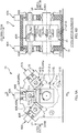
- Fig. 6A is a schematic side view of the heat sealing apparatus 10, and Fig. 6B is an arrow view taken along line B-B in Fig. 6A .
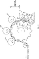
- Fig. 7 is a schematic side view illustrating only a main configuration (a rotating drum 21 and first to third seal rolls 41R, 42R, and 43R) of the apparatus 10. To avoid complication of the drawings, the half-finished product 1a is not illustrated in Figs. 6A or 6B.
- Fig. 6A illustrates a cutaway view of a part of a housing 15 of the apparatus 10 and the like.
- Fig. 6B illustrates a part of the configuration of the apparatus 10 (for example, the seal roll 42R and the rotating drum 21) in front view.
- the heat sealing apparatus 10 includes the rotating drum 21, the first to the third seal rolls 41R, 42R, and 43R, and the housing 15.
- the rotating drum 21 serves as one example of a rotator configured to drive to rotate around a rotation axis that is along the CD direction.
- the first to the third seal rolls 41R, 42R and 43R are disposed at three positions, in a direction of rotation Dc21, of the rotating drum 21 in such a manner as to be opposed to an outer peripheral surface 21a of the rotating drum 21.
- the housing 15 supports these rotating drum 21 and first to third seal rolls 41R, 42R and 43R.
- the half-finished products 1a are wound around the outer peripheral surface 21a of the rotating drum 21.
- the apparatus 10 conveys the half-finished products 1a in the direction of rotation Dc21 through a driving rotation of the rotating drum 21.
- the first to the third seal rolls 41R, 42R, and 43R are disposed in a range where the half-finished products 1a are wound around, with their outer peripheral surfaces 41Ra, 42Ra, and 43Ra being opposed to the outer peripheral surface 21a of the rotating drum 21.
- a formation target part jmp where the main joining portion jm is to be formed in the half-finished product 1a, passes through a position P41R of the first seal roll 41R, which is positioned at the most upstream in the range where the half-finished products 1a are wound around, this formation target part jmp is compressed by the first seal roll 41R and the rotating drum 21, thereby forming a welding portion jm1 of a first stage.
- the rotating drum 21 is rotatably supported around the rotation axis at a fixed position along the CD direct ion using a bearing member (s) 21B fixed to the housing 15 in such a manner as to be substantially immovable.
- the rotating drum 21 is coupled to a servo motor (not illustrated), which serves as a driving source, via an appropriate power transmission mechanism (not illustrated), such as a pulley and a timing belt.
- This drives the rotating drum 21 to rotate around the rotation axis, and this driving rotation operation is controlled so as to coordinate with a conveyance velocity (m/minute) of the half-finished products 1a conveyed from the upstream side in the direction of conveyance to the rotating drum 21, based on a synchronous signal or the like. Accordingly, while the rotating drum 21 is restraining the half-finished products 1a from being extremely pulled and extremely loosened in the direction of conveyance, the rotating drum 21 ensures holding the half-finished products 1a on the outer peripheral surface 21a.
- a plurality of supporting portions 21s, 21s... are provided to protrude at the outer peripheral surface 21a of the rotating drum 21 at intervals of an angle, to the direction of rotation Dc21, corresponding to the product pitch P1 of the half-finished products 1a.
- 12 pieces of the supporting portions 21s and 21s are provided to protrude at intervals of 30° in the direction of rotation Dc21.
- the half-finished products 1a can be held on the outer peripheral surface 21a of the rotating drum 21 in such a manner as to be substantially relatively immovable.
- a plurality of intake holes may be provided on the outer peripheral surface 21a of the rotating drum 21, and through such intake air from these intake holes, the half-finished products 1a may be suctioned to be held to the outer peripheral surface 21a.
- a top surface 21st of the supporting portion 21s is formed in a straight line along the CD direction, with a smooth surface substantially without a depression, corresponding to the linear shape of the above-described main joining portion jm.
- the supporting portion 21s bites into the half-finished product 1a in such a manner as to be substantially relatively immovable.
- the top surface 21st of the supporting portion 21s passes through the positions P41R, P42R, and P43R of the first to the third seal rolls 41R, 42R, and 43R
- the top surface 21st compresses the same part jmp of the half-finished product 1a in corporation with all the rolls of the first to the third seal rolls 41R, 42R, and 43R.
- This enables the degree of welding in the formation target part jmp of the main joining portion jm to be increased in a stepwise manner such as the first stage, the second stage, and the third stage. This effectively contributes to the formation of the main joining portion jm with a high degree of welding, while restraining broken weld (break in the formation target part jmp that may be caused by increase in amount of compression at a time).
- a heating element configured to heat the outer peripheral surface 21a of the rotating drum 21 is incorporated in the rotating drum 21, and the amount of the heat generation of the heating element is adjusted to adjust a temperature of the outer peripheral surface 21a.
- a target temperature of the outer peripheral surface 21a is determined according to the materials constituting the half-finished product 1a, the target temperature is basically set to an appropriately temperature equal to or less than a melting point of a material having the lowest melting point among the materials.
- the heating element (s) is (are) disposed at (a) position (s) point symmetric to the rotation axis of the rotating drum 21 such that the outer peripheral surface 21a of the rotating drum 21 is equally heated across the whole circumference thereof.
- one housing hole (not illustrated) to house the substantially rod-shaped heating element along the rotation axis direction may be formed, with the center of the hole being matched with the rotation axis.
- a plurality of housing holes may be formed at positions at which the whole circumference of the rotating drum 21 is equally divided in the direction of rotation and also the positions at which the housing holes have an equal distance from the rotation axis in a radial direction of rotation, to house the heating elements into the housing holes, respectively.
- the first to the third seal rolls 41R, 42R, and 43R are respectively configured to be, for example, flat rolls whose outer peripheral surfaces 41Ra, 42Ra, and 43Ra are smooth.
- the seal rolls 41R, 42R and 43R are individually rotatably supported by bearing members 41B, 42B, and 43B around the rotation axis that is along the CD direction.
- the seal rolls 41R, 42R and 43R each are coupled to the servo motor (not illustrated), which serves as a driving source, via an appropriate power transmission mechanism (not illustrated) such as a pulley and a timing belt.
- the bearing members 41B, 42B, and 43B of the seal rolls 41R, 42R and 43R are supported to reciprocate in the radial direction of rotation of the rotating drum 21 (direction of contact with / separation from the rotating drum 21) via actuators 41A, 42A, and 43A, such as hydraulic cylinders fixed to the housing 15. Accordingly, the actuators 41A, 42A, and 43A can be controlled to adjust the size of the spaces between the seal rolls 41R, 42R and 43R and the rotating drum 21 or the magnitude of a pressing force (N) in the radial direction of rotation.
- the size of the spaces or the magnitude of the pressing force (N) are adjusted individually for the seal rolls 41R, 42R and 43R such that required degrees of welding can be respectively achieved at the positions of the seal rolls 41R, 42R and 43R.
- the spaces are individually adjusted such that the spaces at the time of compression decrease in the order of the first seal roll 41R, the second seal roll 42R, and the third seal roll 43R. This achieves the aforementioned stepwise increase in the degree of welding.
- hydraulic cylinders are used as the actuators 41A, 42A, and 43A, such individual adjustments of the spaces can be made, for example, as follows.
- the individual adjustments can be made such that pressure values (Pa) of hydraulic oil serving as a working fluid supplied to the hydraulic cylinders 41A, 42A, and 43A are adjusted using a pressure regulation mechanism such as a pressure regulation valve.
- the sizes of the spaces can be obtained through, for example, experiments using an actual apparatus. That is, while the sizes of the spaces are changed in a plurality of levels, the half-finished products 1a are allowed to pass through the heat sealing apparatus 10, and thereafter, the states of the welding portions jmof the half-finished products 1a are checked, thereby being able to obtain the sizes of the spaces.
- These first to third seal rolls 41R, 42R, and 43R also internally incorporate the heating elements (not illustrated), respectively, to heat the outer peripheral surfaces 41Ra, 42Ra, and 43Ra.
- the amounts of heat generation of the heating elements are respectively adjusted to adjust the temperatures of the outer peripheral surfaces 41Ra, 42Ra, and 43Ra.
- the basic concept of the incorporating positions and the target temperature of the outer peripheral surfaces 41Ra, 42Ra, and 43Ra in the rolls 41R, 42R, and 43R is similar to the case of the above-described rotating drum 21, and thus the descriptions thereof are omitted.
- the rolls 41R and 42R are disposed such that at least one welding portion jm1 of the first stage is positioned between the first seal roll 41R (corresponding to the first rotating member of the first compression-bonding apparatus) and the second seal roll 42R (corresponding to the second rotating member of the second compression-bonding apparatus) in the direction of rotation Dc21 when the second seal roll 42R compresses the welding portion jm1 of the first stage.
- first and second seal rolls 41R and 42R are disposed, when the compression by the second seal roll 42R, such that at least one welding portion jm1 of the first stage is positioned between the position P41R, where the first seal roll 41R compresses the half-finished product 1a in corporation with the supporting portion 21s of the rotating drum 21 in the direction of rotation Dc21, and the position P42R, where the second seal roll 42R compresses the half-finished product 1a in corporation with the supporting portion 21s of the rotating drum 21 similarly in the direction of rotation Dc21.
- the transmission of the tensile force in each fiber in the direction of conveyance which may be caused in the continuous bodies 5a, 5a... of the fiber bundles of the half-finished products 1a when the second seal roll 42R compresses the welding portions jm1 of the first stage, is substantially cut off at the welding portion (s) jm1 of the first stage positioned between the first seal roll 41R and the second seal roll 42R in the direction of rotation Dc21. That is, this tensile force in each fiber hardly is transmitted to the position P41R of the first seal roll 41R.
- this can reduce the adverse effect, such as disturbance of fiber distribution, given from the compression process performed for the welding portions jm1 of the first stage by the second seal roll 42R to the formation process performed for the welding portion jm1 of the first stage by the first seal roll 41R positioned at the upstream in the direction of rotation Dc21.
- a large number of the welding portions jm1 of the first stage are positioned between the first seal roll 41R and the second seal roll 42R. That is, it is more preferable to position the plurality of welding portions jm1 of the first stage therebetween than to position only one of the welding portions jm1 of the first stage therebetween as described above.
- the second seal roll 42R from an aspect of increasing the degree of welding at the second seal roll 42R, it is preferable that only one of the welding portions jm1 of the first stage is positioned between the first seal roll 41R and the second seal roll 42R. That is, this allows the second seal roll 42R to compress the welding portion jm1 of the first stage while the heat when the first seal roll 41R forms the welding portion jm1 of the first stage remains. Consequently, the second seal roll 42R easily increases the degree of welding of the welding portion jm2 of the second stage.
- the arrangement positions may be devised with respect to the second seal roll 42R and the third seal roll 43R. That is, as illustrated in Fig. 8 , when the third seal roll 43R compresses the welding portion jm2 of the second stage, the second and third rolls 42R and 43R may be disposed such that at least one welding portion jm2 of the second stage is positioned between the second seal roll 42R and the third seal roll 43R in the direction of rotation Dc21.
- a plurality of welding portions jm2 of the second stage are positioned between the second seal roll 42R and the third seal roll 43R. From the aspect of increasing the degree of welding at the third seal roll 43R, it is preferable that only one of the welding portions jm2 of the second stage is positioned between the second seal roll 42R and the third seal roll 43R. Since these are similar to those described above, the descriptions thereof are omitted.
- one of the first seal roll 41R and the second seal roll 42R preferably compresses the half-finished products 1a when the other seal roll does not compress the half-finished products 1a.
- the tensile force generated in the half-finished products 1a when one of the first seal roll 41R and the second seal roll 42R compresses thereto can be restrained from being transmitted to a part of the half-finished product 1a being compressed by the other seal roll and stretching this part with the tensile force.
- This also restrains the vibration generated in the rotating drum 21 which is caused by the compression by the one seal roll 41R (42R) from affecting the compression performed by the other seal roll 42R (41R) and causing unstable welding process.
- Such a compression-timing-shifting operation can be performed through the adjustments of the position P42R at which the second seal roll 42R is arranged and the position P41R at which the first seal roll 41R is arranged in the direction of rotation Dc21.
- the first and second seal rolls 41R and 42R are disposed such that, when one supporting portion 21s passes through the position P42R where the second seal roll 42R is arranged, another supporting portion 21s does not pass through the position P41R where the first seal roll 41R is arranged, thereby achieving the above-described shifting operation. More specifically, for example, as illustrated in Fig.
- the similar compression-timing-shifting operation may be performed with respect to the second seal roll 42R and the third seal roll 43R.
- the compression timings of the first seal roll 41R to the third seal roll 43R may be set based on the compression-timing-shifting operation as follows. That is, as apparent from Fig. 7 , the third seal roll 43R performs compression, and then the second seal roll 42R performs compression after an interval of a second short period of time. After the compression performed by the second seal roll 42R, the first seal roll 41R performs compression after an interval of a first short period of time. After the compression performed by the first seal roll 41R, the third seal roll 43R performs compression after an interval of a third long period of time.
- the vibration of the rotating drum 21, which is caused by the compression process of the first seal roll 41R performed immediately before, can be sufficiently damped based on the third period of time, before the compression process of the third seal roll 43R is performed, which corresponds to a final finishing among the three-stage compression processes, the third period of time being set longer than the first and second periods of time. Accordingly, the compression process of the third seal roll 43R can be performed highly-accurately.
- a winding start position Pwst of the half-finished products 1a to wind around the rotating drum 21 is set at the position upstream, in the direction of rotation Dc21, from the position P41R at which the first seal roll 41R is arranged.
- the first seal roll 41R compresses the formation target part jmp of the main joining portion jm in the half-finished products 1a in corporation with the supporting portion 21s
- the half-finished product(s) 1a has (have) already been contacted with and supported by at least one supporting portion 21s that is positioned upstream, in the direction of rotation Dc21, from the first seal roll 41R.
- the first seal roll 41R can stably perform the formation process of the welding portions jm1 of the first stage at the formation target parts jmp in the half-finished products 1a.
- two supporting portions 21s and 21s contact to support the half-finished products 1a at the positions upstream, in the direction of rotation Dc21, from the first seal roll 41R; however, this should not be construed in a limiting sense. That is, the number of the supporting portions 21s may be one or may be three or more.
- the half-finishedproducts 1a are wound around the rotating drum 21 from the winding start position Pwst, for example, with an auxiliary roll 51R for winding being disposed at a position near the winding start position Pwst. That is, at this position, the roll 51R which is configured to rotate around a rotation axis along the CD direction is disposed, as the auxiliary roll 51R, near the outer peripheral surface 21a of the rotating drum 21. In this case, further preferably, as illustrated in Fig. 9 , the half-finished products 1a are wound also around the auxiliary roll 51R at a predetermined winding angle.
- a conveyance path for the half-finished products 1a includes an S-shaped conveyance path portion that is positioned upstream, in the direction of rotation Dc21, from the position of the first seal roll 41R. Therefore, when the half-finished products 1a pass through this S-shaped conveyance pathportion, the continuous bodies 5a, 5a... of the fiber bundles of the half-finished products 1a are subjected to a bending process twice in bending directions opposite to each other. This smooths the continuous bodies 5a, 5a... such that the fiber distribution becomes uniform in the continuous bodies 5a and 5a of the fiber bundles in the CD direction.
- Such auxiliary roll 51R may be configured as a driven rotation roll that obtains a rotation force through contact with the half-finished product 1a to guide the half-finished product 1a.
- the auxiliary roll 51R may be configured as a drive rotation roll that obtains a rotation force from an appropriate driving source, such as a servo motor, to rotate.
- a pressing roll 61R (corresponding to a pressing member) may be disposed at a position between the auxiliary roll 51R and the first seal roll 41R in the direction of rotation Dc21.
- the pressing roll 61R is configured to press the half-finished products 1a wound around the outer peripheral surface 21a of the rotating drum 21 to the inside in the radial direction of rotation.
- the continuous bodies 5a, 5a... of the fiber bundles of the half-finished products 1a can be smoothed such that the fiber distribution of the continuous bodies 5a, 5a... becomes uniform in the CD direction, based on the pressing operation by the pressing roll 61R. Accordingly, as described above, unevenness in the weld strength of the main joining portions jm, which may be caused by unevenness in the fiber distribution, can be reduced across the CD direction.
- the pressing roll 61R having such a function is, for example, a roll in which a part thereof including an outer peripheral surface 61Ra is made of a rubber or a resin.
- the roll 61R is supported, around the rotation axis along the CD direction, at both sides by bearing members 61B and 61B which are disposed at the end portions in the CD direction. Additionally, the roll 61R is configured to be reciprocatable in the radial direction of rotation of the rotating drum 21.
- the bearing members 61B and 61B are guided to be reciprocatable in the radial direction of rotation of the rotating drum 21 by a guiding member (not illustrated) such as a linear guide fixed to the housing 15, and that the pressing force in the radial direction of rotation is exerted to the bearing members 61B and 61B from an air cylinder 61A as one example of the actuator 61A that is fixed to the housing 15.
- a guiding member such as a linear guide fixed to the housing 15
- the pressing roll 61R is moved by the supporting portion 21s to the outside in the radial direction of rotation of the rotating drum 21 while resisting the pressing force exerted by the actuator 61A.
- the pressing roll 61R is moved by the pressing force exerted by the actuator 61A to the inside in the radial direction of rotation. Accordingly, the pressing roll 61R periodically reciprocates in the radial direction of rotation at the product pitch P1.
- the magnitude of the pressing force can be varied comparatively largely. This makes it possible to promote the equalization of the fiber distribution of the continuous bodies 5a, 5a... of the fiber bundles.
- the magnitude of the pressing force (N) exerted by the pressing roll 61R is set to the magnitude at which the welding portion (or the compression-bonding portion) is not formed in the half-finished product 1a. Accordingly, the roll 61R is configured as a roll exclusively dedicated to and specialized in the aforementioned process of equalizing the fiber distribution.
- the magnitude of the pressing force (N) at which the weldingportion is not formed canbe obtained by, for example, an experiment using an actual apparatus. That is, the half-finished products 1a are caused to pass through the heat sealing apparatus 10 in a state where the first to the third seal rolls 41R, 42R, and 43R do not perform compression, while the magnitude of the pressing force (N) is being changed at a plurality of levels.
- the adjustments of the pressing force (N) to such a magnitude as above can be achieved by adjusting a pressure value (Pa) of compressed air, serving as a working fluid supplied to the air cylinder 61A, using a pressure regulation mechanism such as a pressure regulation valve.
- recessed portions 21ak recessed in the radial direction of rotation with respect to the outer peripheral surface 21a may be formed each at a position between the supporting portions 21s and 21s immediately adjacent to each another in the outer peripheral surface 21a of the rotating drum 21.
- Such a recessed portion 21ak has a size in which at least a part of the pressing roll 61R comes into. Accordingly, a stroke of the reciprocating movement of the pressing roll 61R can be further increased. Consequently, it becomes possible to further effectively promote the above-described equalization of the fiber distribution.
- the pressing roll 61R may be configured as a driven rotation roll that obtains the rotation force through contact with the half-finished product 1a to guide the half-finished product 1a.
- the pressing roll 61R may be configured as a drive rotation roll that obtains the rotation force from an appropriate driving source, such as a servo motor, to rotate.
- an appropriate driving source such as a servo motor
- a compression spring or the like can be employed in place of the air cylinder.
- the rotating drum 21 is given as one example of the rotator
- the first seal roll 41R and the second seal roll 42R are given as examples of the first rotating member of the first compression-bonding apparatus and the second rotating member of the second compression-bonding apparatus, respectively
- the pressing roll 61R is given as one example of the pressing member, this should not be construed in a limiting sense.
- an endless belt configured to drive to circle may be used as the rotator, first rotating member, second rotating member, and pressing member.
- the endless belt is run around at least two rollers, and a drive rotation force is given to at least one of the rollers from a driving source such as a servo motor. This rotates the belt in a circumferential direction of the belt.
- the above-described embodiments include the three seal rolls 41R, 42R and 43R as examples of a plurality of rolls, the number of seal rolls is not limited to this.
- the seal rolls 41R, 42R and 43R may be two or may be four or more.
- the flat rolls whose outer peripheral surfaces 41Ra, 42Ra, and 43Ra are smooth as examples of the first to the third seal rolls 41R, 42R, and 43R; however, this should not be construed in a limiting sense.
- protrusions (not illustrated) that protrude from the outer peripheral surfaces 41Ra, 42Ra, and 43Ra may be disposed, corresponding to the supporting portions 21s of the rotating drum 21, on the outer peripheral surfaces 41Ra, 42Ra, and 43Ra of the seal rolls 41R, 42R and 43R.
- the protrusion of the first seal roll 41R compresses the formation target part jmp of the main joining portion jm in cooperation with the supporting portion 21s.
- the protrusion on the second seal roll 42R compresses the welding portion jm1 of the first stage in cooperation with the supporting portion 21s.
- the protrusion on the third seal roll 43R compresses the welding portion jm2 of the second stage in cooperation with the supporting portion 21s.
- the top surface 21st of the supporting portion 21s is formed as a smooth surface substantially without a recess; however, this should not be construed in a limiting sense.
- the top surface 21st may have a plurality of recesses in an appropriate arrangement pattern.
- the half-finished products 1a serving as one example of the continuous body of the web member include the continuous sheet 3a of the auxiliary sheets, the continuous sheet 2a of the base material sheets, the continuous bodies 5a, 5a... of the four fiber bundles, and the continuous sheet 7a of the oblong sheets; however, this should not be construed in a limiting sense. That is, it is only necessary that the half-finished products 1a have at least one bundle of the continuous body 5a as the fiber bundle. Accordingly, for example, any one or two of all of the continuous sheet 3a of the auxiliary sheets, the continuous sheet 2a of the base material sheets, and the continuous sheet 7a of the oblong sheets may be omitted. Further, the continuous body 5a of the fiber bundle is not limited to four bundles.
- the continuous sheet 3a of the auxiliary sheets, the continuous sheet 2a of the base material sheets, the continuous bodies 5a, 5a... of the four fiber bundles, and the continuous sheet 7a of the oblong sheets have already been stacked and sent to the heat sealing apparatus 10; however, this should not be construed in a limiting sense. That is, some or all of the continuous sheets 3a, 2a, and 7a and continuous bodies 5a, 5a... of the fiber bundles may be individually conveyed up to the position of the auxiliary roll 51R of the heat sealing apparatus 10. That is, the stacked state as described above maybe configured such that these members are joined to one another at the position of the roll 51R.
Landscapes
- Engineering & Computer Science (AREA)
- Textile Engineering (AREA)
- Mechanical Engineering (AREA)
- Physics & Mathematics (AREA)
- Fluid Mechanics (AREA)
- Treatment Of Fiber Materials (AREA)
- Nonwoven Fabrics (AREA)
- Cleaning Implements For Floors, Carpets, Furniture, Walls, And The Like (AREA)
- Laminated Bodies (AREA)
- Absorbent Articles And Supports Therefor (AREA)
Abstract
Description
- The present invention relates to a method and an apparatus for forming a compression-bonding portion in a continuous body of a web member with a fiber bundle such as a tow, which is used to manufacture a cleaning web member.
- Conventionally, there is known a cleaning web member that includes a fiber bundle such as a tow used for cleaning (Patent Literature 1) . To integrally bundle and fix fibers constituting the fiber bundle, a compression-bonding portion is formed in the web member.
- [PTL 1] 2005-40641
-
Fig. 1 is a schematic explanatory view of a first reference example illustrating a process to form a compression-bonding portion jm'. Fiber bundles of a web member when being sent in this process are in a state of being continuous in a predetermined direction while the fiber direction is set along the predetermined direction. Therefore, the web member is also in a state of being acontinuous body 1a' that is continuous in the predetermined direction. In this process, while thecontinuous body 1a' of the web member is conveyed in the predetermined direction set as a direction of conveyance, the compression-bonding portions jm' are formed at intervals each corresponding to a product pitch in the direction of conveyance. - Here, the compression-bonding portions jm' are formed, for example, in two stages. That is, for example, a first compression-bonding apparatus 41' and a second compression-bonding apparatus 42' are disposed at two positions in a direction of rotation Dc21' of a rotating drum 21' which is configured to convey the
continuous body 1a' of the web member while holding it on an outerperipheral surface 21a'. When a formation target part jmp' of the compression-bonding portion jm' in thecontinuous body 1a' of the web member passes through a position of the first compression-bonding apparatus 41' , the first compression-bonding apparatus 41' compresses the formation target part jmp' in cooperation with a supportingportion 21s' on the outerperipheral surface 21a' of the rotating drum 21' , to form a compression-bonding portion jm1' of a first stage. Thereafter, this compression-bonding portion jm1' of the first stage passes through a position of the second compression-bonding apparatus 42', which is positioned downstream in the direction of rotation Dc21'. At this time, the second compression-bonding apparatus 42' further compresses the compression-bonding portion jm1' of the first stage in cooperation with the supportingportion 21s' on the outerperipheral surface 21a' of the rotating drum 21', to form a compression-bonding portion jm2' of a second stage. Consequently, the compression-bonding portion jm' is formed in thecontinuous body 1a' of the web member in two stages. - However, in this method, a compression process performed for the compression-bonding portion jm1' of the first stage by the second compression-bonding apparatus 42' may adversely affect the process of forming the compression-bonding portion jm1' of the first stage, which is performed by the first compression-bonding apparatus 41' positioned upstream in the direction of rotation Dc21'. For example, when the second compression-bonding apparatus 42' compresses the compression-bonding portion jm1' of the first stage, a tensile force F may be generated along the direction of conveyance in the
continuous body 1a' of the web member. Such tensile force F may be transmitted to the upstream side in the direction of rotation Dc21' in each fiber of the fiber bundle. This may result in disturbance of a fiber distribution of the fiber bundle. - In this respect, as illustrated in a second reference example in
Fig. 2 , if at least one compression-bonding portion jm1' of the first stage is positioned between the first compression-bonding apparatus 41' and the second compression-bonding apparatus 42' at a time when the second compression-bonding apparatus 42' compresses the compression-bonding portion jm1' of the first stage, the transmission of the tensile force F in each fiber is mostly cut off at a position of this compression-bonding portion jm1' of the first stage. That is, this tensile force F in each fiber is difficult to be transmitted up to the position of the first compression-bonding apparatus 41'. This reduces adverse effects, for example, exerted by the disturbance of the distribution of the fiber bundles as described above, onto the process of forming the compression-bonding portion jm1' of the first stage. - The present disclosure has been made in view of conventional problems as described above. An aspect of the present disclosure is to restrain negative effects caused by a compression process of a compression-bonding portion of a first stage performed by a second compression-bonding apparatus, from being exerted on a formation process of the compression-bonding portion of the first stage performed by a first compression-bonding apparatus positioned upstream in a direction of rotation.
- An aspect of the present disclosure to achieve an aspect described above is a method for forming compression-bonding portions in a continuous body of a web member including a fiber bundle, while conveying the continuous body in a predetermined direction set as a direction of conveyance, the fiber bundle being continuous in the predetermined direction while a fiber direction is set along the predetermined direction, the compression-bonding portions being formed at intervals in the direction of conveyance, the method comprising: rotating a rotator around a rotation axis along a CD direction intersecting with the direction of conveyance, while holding the continuous body of the web member on an outer peripheral surface of the rotator, to convey the continuous body of the web member in a direction of rotation of the rotator set as the direction of conveyance; compressing a formation target part of each of the compression-bonding portions in the continuous body of the web member, using a first compression-bonding apparatus and the rotator, when the formation target part passes through a position of the first compression-bonding apparatus disposed at a predetermined position in the direction of rotation, to form the compression-bonding portions of a first stage; and further compressing each of the compression-bonding portions of the first stage using a second compression-bonding apparatus and the rotator, when the compression-bonding portion of the first stage passes through a position of the second compression-bonding apparatus disposed downstream in the direction of rotation from the first compression-bonding apparatus, to form the compression-bonding portions of a second stage, the compression-bonding portions of the first stage including at least one compression-bonding port ion that is positioned between the first compression-bonding apparatus and the second compression-bonding apparatus in the direction of rotation when the second compression-bonding apparatus compresses the compression-bonding portion of the first stage.
- An apparatus for forming compression-bonding portions in a continuous body of a web member including a fiber bundle, while conveying the continuous body in a predetermined direction set as a direction of conveyance, the fiber bundle being continuous in the predetermined direction while a fiber direction is set along the predetermined direction, the compression-bonding portions being formed at intervals in the direction of conveyance, the apparatus comprising: a conveying apparatus configured to rotate a rotator around a rotation axis along a CD direction intersecting with the direction of conveyance, while holding the continuous body of the web member on an outer peripheral surface of the rotator, to convey the continuous body of the web member in a direction of rotation of the rotator set as the direction of conveyance; a first compression-bonding apparatus configured to compress a formation target part of each of the compression-bonding portions in the continuous body of the web member in corporation with the rotator, when the formation target part passes through a predetermined position in the direction of rotation, to form the compression-bonding portions of a first stage; and a second compression-bonding apparatus configured to further compress the compression-bonding portion of the first stage in corporation with the rotator, when each of the compression-bonding portions of the first stage passes through a position downstream in the direction of rotation from the predetermined position, to form the compression-bonding portions of a second stage, the compression-bonding portions of the first stage including at least one compression-bonding portion that is positioned between the first compression-bonding apparatus and the second compression-bonding apparatus in the direction of rotation when the second compression-bonding apparatus compresses the compression-bonding portion of the first stage.
- Other features of the present disclosure will be become apparent from descriptions of the present specification and of the accompanying drawings.
- According to the present disclosure, adverse effects caused by a compression process of a compression-bonding portion of a first stage performed by a second compression-bonding apparatus can be restrained from being exerted on a formation process of the compression-bonding portion of the first stage performed by a first compression-bonding apparatus positioned upstream in a direction of rotation.
-
- [
Fig. 1] Fig. 1 is a schematic explanatory view of a first reference example illustrating a process of forming a compression-bonding portion jm'. - [
Fig. 2] Fig. 2 is a schematic explanatory view of a second reference example illustrating a process. - [
Fig. 3] Fig. 3 is a perspective view of acleaning web member 1 manufactured using a method and anapparatus 10 for forming a compression-bonding portion according to an embodiment of the present disclosure. - [
Fig. 4] Fig. 4A is a plan view of acleaning web member 1, andFig. 4B is a cross-sectional view of acleaning web member 1 taken along line B-B inFig. 4A . - [
Fig. 5] Fig. 5A is a schematic diagram of half-finishedproducts 1a of acleaning web members 1 immediately before being sent to aheat sealing apparatus 10 serving as one example of a formation apparatus according to an embodiment of the present disclosure, andFig. 5B is a schematic diagram of half-finishedproducts 1a after half-finishedproducts 1a pass through theapparatus 10. - [
Fig. 6] Fig. 6A is a schematic side view of anapparatus 10, andFig. 6B is an arrow view thereof taken along line B-B inFig. 6A . - [
Fig. 7] Fig. 7 is a schematic side view illustrating only a main configuration (a rotatingdrum 21 and first tothird seal rolls apparatus 10. - [
Fig. 8] Fig. 8 is a schematic side view of the same. - [
Fig. 9] Fig. 9 is a schematic side view of the same. - [
Fig. 10] Fig. 10 is a schematic side view of aheat sealing apparatus 10 including apressing roll 61R. - [
Fig. 11] Fig. 11 is a schematic side view of an example in which recessed portions 21ak are provided to an outerperipheral surface 21a of a rotatingdrum 21. - At least the following matters will become apparent from descriptions of the present specification and the accompanying drawings.
- A method for forming compression-bonding portions in a continuous body of a web member including a fiber bundle, while conveying the continuous body in a predetermined direction set as a direction of conveyance, the fiber bundle being continuous in the predetermined direction while a fiber direction is set along the predetermined direction, the compression-bonding portions being formed at intervals in the direction of conveyance, the method comprising: rotating a rotator around a rotation axis along a CD direction intersecting with the direction of conveyance, while holding the continuous body of the web member on an outer peripheral surface of the rotator, to convey the continuous body of the web member in a direction of rotation of the rotator set as the direction of conveyance; compressing a formation target part of each of the compression-bonding portions in the continuous body of the web member, using a first compression-bonding apparatus and the rotator, when the formation target part passes through a position of the first compression-bonding apparatus disposed at a predetermined position in the direction of rotation, to form the compression-bonding portions of a first stage; and further compressing each of the compression-bonding portions of the first stage using a second compression-bonding apparatus and the rotator, when the compression-bonding portion of the first stage passes through a position of the second compression-bonding apparatus disposed downstream in the direction of rotation from the first compression-bonding apparatus, to form the compression-bonding portions of a second stage, the compression-bonding portions of the first stage including at least one compression-bonding portion that is positioned between the first compression-bonding apparatus and the second compression-bonding apparatus in the direction of rotation when the second compression-bonding apparatus compresses the compression-bonding portion of the first stage.
- With the method for forming the compression-bonding portions in the continuous body of the web member including the fiber bundle, when the second compression-bonding apparatus compresses the compression-bonding portions of the first stage, at least one of the compression-bonding portions of the first stage is positioned between the first compression-bonding apparatus and the second compression-bonding apparatus. Accordingly, transmission of a tensile force in each fiber in the direction of conveyance, which may occur in the continuous body of the web member when the compression-bonding portion of the first stage is compressed, is almost cut off at the at least one of the compression-bonding portions of the first stage positioned between the first compression-bonding apparatus and the second compression-bonding apparatus in the direction of rotation. That is, this tensile force in each fiber is hardly transmitted up to the position of the first compression-bonding apparatus. Therefore, the adverse effects exerted from the compression process performed for the compression-bonding portion of the first stage by the second compression-bonding apparatus onto the process of forming the compression-bonding portion of the first stage performed using the first compression-bonding apparatus positioned upstream in the direction of rotation.
- In the method for forming the compression-bonding portions in the continuous body of the web member including the fiber bundle, it ispreferablethatwhenthe second compression-bonding apparatus compresses the compression-bonding portion of the first stage, a plurality of the compression-bonding portions of the first stage are positioned between the first compression-bonding apparatus and the second compression-bonding apparatus in the direction of rotation.
- With the method for forming the compression-bonding portions in the continuous body of the web member including the fiber bundle, when the second compression-bonding apparatus compresses each compression-bonding portion of the first stage, a plurality of the compression-bonding portions of the first stage is positioned between the first compression-bonding apparatus and the second compression-bonding apparatus. Accordingly, the transmission of the tensile force in each fiber can be reliably cut off at the position(s) between the first compression-bonding apparatus and the second compression-bonding apparatus in the direction of rotation.
- In the method for forming the compression-bonding portions in the continuous body of the web member including the fiber bundle, it is preferable that when the second compression-bonding apparatus compresses the compression-bonding portion of the first stage, only one of the compression-bonding portions of the first stage is positioned between the first compression-bonding apparatus and the second compression-bonding apparatus in the direction of rotation.
- With the method for forming the compression-bonding portions in the continuous body of the web member including the fiber bundle, when the second compression-bonding apparatus compresses each compression-bonding portion of the first stage, only one of the compression-bonding portions of the first stage is positioned between the first compression-bonding apparatus and the second compression-bonding apparatus. Accordingly, the second compression-bonding portion can compress the compression-bonding portion of the first stage while the transmission of the tensile force in each fiber is appropriately cut off and heat at the time when the first compression-bonding apparatus forms the compression-bonding portion of the first stage remains. Consequently, the second compression-bonding apparatus easily forms the compression-bonding portions of the second stage.
- In the method for forming the compression-bonding portions in the continuous body of the web member including the fiber bundle, it is preferable that one of the first compression-bonding apparatus and the second compression-bonding apparatus perform compression, while an other of the first compression-bonding apparatus and the second compression-bonding apparatus does not perform compression.
- According to the method for forming the compression-bonding portions in the continuous body of the web member including the fiber bundle, it is possible to restrain, for example, the tensile force caused in the continuous body of the web member when one of the first compression-bonding apparatus and the second compression-bonding apparatus performs compression, from being transmitted to pull a part of the continuous body of the web member that is being compressed by the other compression-bonding apparatus. Accordingly, this can restrain the first compression-bonding apparatus and the second compression-bonding apparatus from adversely affecting their formation processes each other.
- In the method for forming the compression-bonding portions in the continuous body of the web member including the fiber bundle, it is preferable that the continuous body of the web member is wound around the outer peripheral surface of the rotator, with a winding start position to wind around the rotator being set at a position upstream in the direction of rotation from the first compression-bonding apparatus.
- With the method for forming the compression-bonding portions in the continuous body of the web member including the fiber bundle, the continuous body of the web member is wound around the rotator from the position upstream with respect to the first compression-bonding apparatus. Accordingly, the first compression-bonding apparatus can stably perform the compression process for the continuous body of the web member.
- In the method for forming the compression-bonding portions in the continuous body of the web member including the fiber bundle, it is preferable that a plurality of supporting portions are provided in the outer peripheral surface of the rotator in such a manner as to protrude at intervals of an angle to the direction of rotation, the angle corresponding to a product pitch of the web member, the supporting portions being configured to support formation target parts in the continuous body of the web member, when each of the supporting portions passes through the position of the first compression-bonding apparatus, the supporting portion compresses each of the formation target parts in corporation with the first compression-bonding apparatus, when the supporting portion passes through the position of the second compression-bonding apparatus, the supporting portion compresses the compression-bonding portion of the first stage in corporation with the second compression-bonding apparatus, and when the first compression-bonding apparatus compresses the formation target part in corporation with the supporting port ion, the continuous body of the web member has already been supported by at least one of the supporting portions positioned upstream in the direction of rotation from the first compression-bonding apparatus.
- With the method for forming the compression-bonding portions in the continuous body of the web member including the fiber bundle, when the first compression-bonding apparatus compresses each formation target part in corporation with the supporting portion, a supporting portion immediately adjacent to the supporting portion positioned upstream in the direction of rotation also has already supported the continuous body of the web member. In specific, these two supporting portions protrude with respect to the outer peripheral surface, and thus the supporting portions each dig into the web member in the thickness direction to support the web member. Accordingly, while the first compression-bonding apparatus is performing compression, a relative movement of the continuous body of the web member can be appropriately restricted by at least two supporting portions. Consequently, the first compression-bonding apparatus can stably perform the process of forming the compression-bonding portions of the first stage.
- In the method for forming the compression-bonding portions in the continuous body of the web member including the fiber bundle, it is preferable that the first compression-bonding apparatus includes a first rotating member, the first rotating member being configured to rotate around a rotation axis along the CD direction, while a smooth outer peripheral surface of the first rotating member is opposed to the outer peripheral surface of the rotator, the second compression-bonding apparatus includes a second rotating member, the second rotating member being configured to rotate around a rotation axis along the CD direction, while a smooth outer peripheral surface of the second rotating member is opposed to the outer peripheral surface of the rotator, the supporting portion compresses the formation target part in corporation with the outer peripheral surface of the first rotating member, and the supporting portion compresses the compression-bonding portion of the first stage in corporation with the outer peripheral surface of the second rotating member.
- With the method for forming the compression-bonding portions in the continuous body of the web member including the fiber bundle, the supporting portions of the rotator form the compression-bonding portions of the first stage in corporation with the first rotating member having a smooth outer peripheral surface. The supporting portions form the compression-bonding portions of the second stage in corporation with the second rotating member having a smooth outer peripheral surface. Accordingly, the compression-bonding portions can be stably formed.
- In the method for forming the compression-bonding portions in the continuous body of the web member including the fiber bundle, it is preferable that a pressing member is disposed at a position upstream in the direction of rotation from the first compression-bonding apparatus, the pressing member being configured to press the continuous body of the web member held on the outer peripheral surface of the rotator, to an inside in a radial direction of rotation of the rotator.
- With the method for forming the compression-bonding portions in the continuous body of the web member including the fiber bundle, the fiber bundle can be leveled such that the fiber distribution in the CD direction of the fiber bundle in the continuous body of the web member becomes uniform based on the pressing operation of the pressing member. This can reduce the unevenness in the CD direction in compression-bonding strength of the compression-bonding portions which may be caused by unevenness in fiber distribution. Consequently, the fibers can be firmly fixed at the compression-bonding portions, thereby restraining the fibers from falling off.
- In the method for forming the compression-bonding portions in the continuous body of the web member including the fiber bundle, it is preferable that at least one compression-bonding apparatus is disposed at a position downstream in the direction of rotation from the second compression-bonding apparatus, the at least one compression-bonding apparatus being configured to compress the compression-bonding portion of the second stage, a compression process is performed for the continuous body of the web member at intervals of a predetermined period of time, in an order from a compression-bonding apparatus positioned downstream in the direction of rotation to a compression-bonding apparatus positioned adjacently upstream thereto, and after a compression process of a compression-bonding apparatus positioned most upstream in the direction of rotation is completed, a compression process is performed by a compression-bonding apparatus positioned most downstream in the direction of rotation, after an interval of a longest period of time among the intervals of the predetermined period of time.
- With the method for forming the compression-bonding portions in the continuous body of the web member including the fiber bundle, an interval of a period of time that is longer than any intervals set between the compression processes is set before the compression process performed by the compression-bonding apparatus positioned most downstream in the direction of rotation, which corresponds to a final finishing process among the compression processes of the plurality of stages. Thus, vibrations of the rotator caused by the compression process performed immediately before by the compression-bonding apparatus positioned most upstream can be sufficiently damped based on such an interval of a long period of time. Accordingly, the compression-bonding apparatus most downstream can perform the compression process with high precision.
- An apparatus for forming compression-bonding portions in a continuous body of a web member including a fiber bundle, while conveying the continuous body in a predetermined direction set as a direction of conveyance, the fiber bundle being continuous in the predetermined direction while a fiber direction is set along the predetermined direction, the compression-bonding portions being formed at intervals in the direction of conveyance, the apparatus comprising: a conveying apparatus configured to rotate a rotator around a rotation axis along a CD direction intersecting with the direction of conveyance, while holding the continuous body of the web member on an outer peripheral surface of the rotator, to convey the continuous body of the web member in a direction of rotation of the rotator set as the direction of conveyance; a first compression-bonding apparatus configured to compress a formation target part of each of the compression-bonding portions in the continuous body of the web member in corporation with the rotator, when the formation target part passes through a predetermined position in the direction of rotation, to form the compression-bonding portions of a first stage; and a second compression-bonding apparatus configured to further compress the compression-bonding portion of the first stage in corporation with the rotator, when each of the compression-bonding portions of the first stage passes through a position downstream in the direction of rotation from the predetermined position, to form the compression-bonding portions of a second stage, the compression-bonding portions of the first stage including at least one compression-bonding portion that is positioned between the first compression-bonding apparatus and the second compression-bonding apparatus in the direction of rotation when the second compression-bonding apparatus compresses the compression-bonding portion of the first stage.
- With the apparatus for forming the compression-bonding portions in the continuous body of the web member including the fiber bundle, such effects similar to the case of the above-described manufacturing method can be exerted.
-
Fig. 3 is a perspective view of a cleaningweb member 1 manufactured using a method and anapparatus 10 for forming a compression-bonding portion according to an embodiment of the present disclosure.Fig. 4A is a plan view of the cleaningweb member 1, andFig. 4B is a cross-sectional view of the cleaningweb member 1 taken along line B-B inFig. 4A . - As illustrated in
Figs. 3 and4A , this cleaningweb member 1 has a planar shape of a substantially rectangular shape having a longitudinal direction and a width direction. As illustrated inFigs. 3 and4B , abase material sheet 2, anauxiliary sheet 3, afiber bundle member 5G, and aoblong sheet 7 are disposed in a thickness direction. Theauxiliary sheet 3 covers a top surface of thebase material sheet 2. Thefiber bundle member 5G covers a lower surface of thebase material sheet 2 to serve as a main brush portion. Theoblong sheet 7 is disposed at a lower surface with respect to thefiber bundle member 5G to serve as an auxiliary brush portion. Between theauxiliary sheet 3 and thebase material sheet 2, void portions SP and SP are formed such that ahandle member 9 is inserted into the void portions SP and SP to be fixed. Accordingly, two-forkedinsertions handle member 9 are inserted into these voidportions SP and SP. Thus, the cleaningweb member 1 is used for cleaning of, for example, a desk, with the lower surface and both ends, in the width direction, of the cleaningweb member 1 being used as wiping surfaces. - As illustrated in
Fig. 4B , thefiber bundle member 5G is a member of a plurality of bundles of fiber bundles 5, 5... stacked in a thickness direction. Although, in this example, the four fiber bundles 5, 5... are stacked in the thickness direction as one example of the plurality of bundles, the number of the fiber bundles 5, 5... of thefiber bundle member 5G is not limited to this. For example, the number of the fiber bundles 5, 5... may be one bundle, two bundles, three bundles, or the like. - The fiber bundles 5 each include tows having a fineness of, for example, 3.5 dtex (diameter of 18 to 25 µm) as a large number of continuous fibers. However, the fineness of the tow is not limited to 3.5 dtex. For example, a given value may be selected from a range of 1.1 to 10 dtex (diameter of about 6 to about 60 µm), and further the respective fiber bundles 5 may include the tows having a plurality of finenesses in a range of 1.1 to 10 dtex.
- The fiber directions of the fiber bundles 5 are along the width direction of the cleaning
web member 1. That is, the longitudinal directions of the tows are along the width direction of the cleaningweb member 1. This basically forms both ends in the width direction as distal end portions of the brush portion. Note that, since these tows are flexibly bent and deformable, bending the distal end portions of the tows to the lower surface side of the cleaningweb member 1 allows the lower surface to serve as the distal end portion of the brush portion. In this example, all the fibers of the fiber bundles 5 are configured with the tows; however, this should not be construed in a limiting sense. That is, the fiber bundle 5 may include a fiber other than the tow. - Note that, the tow is a fiber made of a continuous filament and is a fiber made of a single component such as polyethylene terephthalate (PET), polypropylene (PP), and polyethylene (PE), a composite fiber with a sheath-core structure whose sheath/core is PE/PET and PE/PP, or a side-by-side composite fiber such as PE/PET and PE/PP. The cross-sectional shape may be a circular shape or a shape other than the circular shape. The fiber may have a crimp, and in this case, a crimper process is performed when the filaments are a manufactured. Further, the number of crimps is increased with a preheat calendar or hot air treatment. A transport roll transports the crimped tows. At this time, a tensile force is provided to the tows in longitudinal directions of the filaments, and the tensile force is released. Repeating this process opens the continuous filaments of the tows so as to be individually separated into pieces.
- As illustrated in
Figs. 3 ,4A, and 4B , thebase material sheet 2 and theauxiliary sheet 3 both have a substantially rectangular shape in planar shape. While the lengths thereof in the width direction are set to the same dimensions as one another, the length in the longitudinal direction of thebase material sheet 2 is set longer than that of theauxiliary sheet 3. Accordingly, theauxiliary sheet 3 is stacked on thebase material sheet 2 such that both ends 2e and 2e of thebase material sheet 2 in the longitudinal direction protrude, by a predetermined length, to the outside from bothends auxiliary sheet 3 in the longitudinal direction. - In this example, both the
base material sheet 2 and theauxiliary sheet 3 have zigzag slits k, k... along the width direction, with intervals in the longitudinal direction, at respective end portions in the width direction. These slits k, k... form a plurality of zigzag strip pieces along the width direction at the end portions, in the width direction, of thebase material sheet 2 and theauxiliary sheet 3. Note that these slits k, k... may be omitted. - The
base material sheet 2 and theauxiliary sheet 3 are, for example, made of a nonwoven fabric containing a thermoplastic fiber. The thermoplastic fiber includes, for example, PE, PP, and PET fiber, a composite fiber of PE and PET (for example, a composite fiber having a sheath-core structure in which core is PE and sheath is PET), and a composite fiber of PE and PP (for example, a composite fiber having a sheath-core structure in which core is PET and sheath is PE). An aspect of the nonwoven fabric is, for example, a thermally bonded nonwoven fabric, a spunbonded nonwoven fabric, and a spunlace nonwoven fabric. Note that the materials of thesebase material sheet 2 andauxiliary sheet 3 are not limited to the nonwoven fabric. For example, the materials may be a woven fabric or a film. - The
oblong sheet 7 is formed of a flexible sheet such as a nonwoven fabric containing a thermoplastic fiber or a thermoplastic resin film. Theoblong sheet 7 is formed into a substantially rectangular shape having the same planar surface size as that of thebase material sheet 2. At end portions in the width direction of theoblong sheet 7, zigzag slits (not illustrated) are formed along the width direction with intervals in the longitudinal direction. These slits form a plurality of zigzag strip pieces (not illustrated) along the width direction at the end portions in the width direction of theoblong sheet 7. Note that thisoblong sheet 7 may be omitted. - These
auxiliary sheet 3,base material sheet 2,fiber bundle member 5G of all of the four fiber bundles 5, 5, 5, and 5, andoblong sheet 7 are stacked in the thickness direction in this order. As illustrated inFigs. 4A and 4B , thesesheets sheets sheets - A plurality of auxiliary joining portions js, js... , which join the
auxiliary sheet 3 and thebase material sheet 2 together by welding or the like, are formed to be aligned in the longitudinal direction at positions on both sides of this main joining portion jm in the width direction. By virtue of these auxiliary joining portions js, js..., the aforementioned void portions SP and SP, into which thehandle member 9 is inserted between theauxiliary sheet 3 and thebase material sheet 2 to be fixed, are formed at positions between the main joining portion jm and the auxiliary joining portions js, js.... - Such
cleaning web members 1 are manufactured on a manufacturing line. The manufacturing line includes theheat sealing apparatus 10 as one example of a formation apparatus, which is configured to form the above-described main joining portion jm. -
Fig. 5A is a schematic diagram of half-finished products 1a (corresponding to a continuous body of the web member) of the cleaningweb members 1 immediately before being sent to thisheat sealing apparatus 10. At this time, the half-finished products 1a are in a state of acontinuous body 1a in which the plurality of cleaningweb members finished products 1a, theauxiliary sheets 3, thebase material sheets 2, and theoblong sheets 7 are individually in a state ofcontinuous sheets continuous bodies continuous sheet 3a of the auxiliary sheet, thecontinuous sheet 2a of the base material sheets, thecontinuous bodies continuous sheet 7a of the oblong sheets are stacked in the thickness direction in this order. Thecontinuous sheet 3a of the auxiliary sheets and thecontinuous sheet 2a of the base material sheets have already been joined with the auxiliary joining portions js, js.... - As illustrated in
Fig. 5B , while theheat sealing apparatus 10 are conveying the half-finished products 1a in a direction in which the half-finished products 1a continue, which serves as the direction of conveyance, theheat sealing apparatus 10 forms the main joining portions jm on the half-finished products 1a at a product pitch P1 in the direction of conveyance. Then, the half-finished products 1a in which the main joining portions jm are formed are conveyed to a cutting apparatus (not illustrated) positioned downstream from theheat sealing apparatus 10. The apparatus is configured to cut at each intermediate position Pm, as a cutting target position, between the main joining portions jm and jm immediately adjacent to each another in the direction of conveyance, and the cleaningweb members 1 are formed as described hereinabove. - As illustrated in
Figs. 5A and 5B , in theheat sealing apparatus 10, a direction corresponding to the width direction of the half-finished product 1a is referred to as a "CD direction." Three directions, which are the CD direction, the direction of conveyance, and the thickness direction of the half-finished product 1a, are in such a relationship as to be orthogonal to one another. -
Fig. 6A is a schematic side view of theheat sealing apparatus 10, andFig. 6B is an arrow view taken along line B-B inFig. 6A .Fig. 7 is a schematic side view illustrating only a main configuration (arotating drum 21 and first to third seal rolls 41R, 42R, and 43R) of theapparatus 10. To avoid complication of the drawings, the half-finished product 1a is not illustrated inFigs. 6A or 6B. Fig. 6A illustrates a cutaway view of a part of ahousing 15 of theapparatus 10 and the like.Fig. 6B illustrates a part of the configuration of the apparatus 10 (for example, theseal roll 42R and the rotating drum 21) in front view. - As illustrated in
Figs. 6A and 6B , theheat sealing apparatus 10 includes therotating drum 21, the first to the third seal rolls 41R, 42R, and 43R, and thehousing 15. Therotating drum 21 serves as one example of a rotator configured to drive to rotate around a rotation axis that is along the CD direction. The first to the third seal rolls 41R, 42R and 43R are disposed at three positions, in a direction of rotation Dc21, of therotating drum 21 in such a manner as to be opposed to an outerperipheral surface 21a of therotating drum 21. Thehousing 15 supports theserotating drum 21 and first to third seal rolls 41R, 42R and 43R. - As illustrated in
Fig. 7 , in theapparatus 10, the half-finished products 1a are wound around the outerperipheral surface 21a of therotating drum 21. With the half-finished products 1a being held in a state where a relative sliding hardly occurs, theapparatus 10 conveys the half-finished products 1a in the direction of rotation Dc21 through a driving rotation of therotating drum 21. The first to the third seal rolls 41R, 42R, and 43R are disposed in a range where the half-finished products 1a are wound around, with their outer peripheral surfaces 41Ra, 42Ra, and 43Ra being opposed to the outerperipheral surface 21a of therotating drum 21. - Accordingly, as illustrated in
Fig. 7 , when a formation target part jmp, where the main joining portion jm is to be formed in the half-finished product 1a, passes through a position P41R of thefirst seal roll 41R, which is positioned at the most upstream in the range where the half-finished products 1a are wound around, this formation target part jmp is compressed by thefirst seal roll 41R and therotating drum 21, thereby forming a welding portion jm1 of a first stage. When the welding portion jm1 of this first stage passes through a position P42R of thesecond seal roll 42R, which is positioned downstream from thefirst seal roll 41R, the welding portion jm1 of the first stage is further compressed by thesecond seal roll 42R and therotating drum 21, thereby forming a welding portion jm2 of a second stage. Furthermore, when the welding portion jm2 of this second stage passes through a position P43R of thethird seal roll 43R, which is positioned downstream from thesecond seal roll 42R, the welding portion jm2 of the second stage is further compressed by thethird seal roll 43R and therotating drum 21, thereby forming a welding portion jm3 of a third stage. This welding portion jm3 of the third stage corresponds to the above-described main joining portion jm, the main joining portion jm is formed in the half-finished product 1a as described hereinabove. - The following describes the
rotating drum 21, the first to the third seal rolls 41R, 42R, and 43R, and the like in detail. - As illustrated in
Fig. 6A , therotating drum 21 is rotatably supported around the rotation axis at a fixed position along the CD direct ion using a bearing member (s) 21B fixed to thehousing 15 in such a manner as to be substantially immovable. Therotating drum 21 is coupled to a servo motor (not illustrated), which serves as a driving source, via an appropriate power transmission mechanism (not illustrated), such as a pulley and a timing belt. This drives therotating drum 21 to rotate around the rotation axis, and this driving rotation operation is controlled so as to coordinate with a conveyance velocity (m/minute) of the half-finished products 1a conveyed from the upstream side in the direction of conveyance to therotating drum 21, based on a synchronous signal or the like. Accordingly, while therotating drum 21 is restraining the half-finished products 1a from being extremely pulled and extremely loosened in the direction of conveyance, therotating drum 21 ensures holding the half-finished products 1a on the outerperipheral surface 21a. - As illustrated in
Fig. 6A , a plurality of supportingportions peripheral surface 21a of therotating drum 21 at intervals of an angle, to the direction of rotation Dc21, corresponding to the product pitch P1 of the half-finished products 1a. For example, in this example, 12 pieces of the supportingportions - Accordingly, with the supporting
portions 21s inFig. 7 digging into the half-finished products 1a in the thickness direction, the half-finished products 1a can be held on the outerperipheral surface 21a of therotating drum 21 in such a manner as to be substantially relatively immovable. Note that, in order to hold these half-finished products 1a to be substantially relatively immovable with more reliability, a plurality of intake holes (not illustrated) may be provided on the outerperipheral surface 21a of therotating drum 21, and through such intake air from these intake holes, the half-finished products 1a may be suctioned to be held to the outerperipheral surface 21a. - Further, as illustrated in
Fig. 6B , a top surface 21st of the supportingportion 21s is formed in a straight line along the CD direction, with a smooth surface substantially without a depression, corresponding to the linear shape of the above-described main joining portion jm. As has been described, the supportingportion 21s bites into the half-finished product 1a in such a manner as to be substantially relatively immovable. - Accordingly, as illustrated in
Fig. 7 , when the top surface 21st of the supportingportion 21s passes through the positions P41R, P42R, and P43R of the first to the third seal rolls 41R, 42R, and 43R, the top surface 21st compresses the same part jmp of the half-finished product 1a in corporation with all the rolls of the first to the third seal rolls 41R, 42R, and 43R. This enables the degree of welding in the formation target part jmp of the main joining portion jm to be increased in a stepwise manner such as the first stage, the second stage, and the third stage. This effectively contributes to the formation of the main joining portion jm with a high degree of welding, while restraining broken weld (break in the formation target part jmp that may be caused by increase in amount of compression at a time). - Since this
apparatus 10 is theheat sealing apparatus 10, a heating element (not illustrated) configured to heat the outerperipheral surface 21a of therotating drum 21 is incorporated in therotating drum 21, and the amount of the heat generation of the heating element is adjusted to adjust a temperature of the outerperipheral surface 21a. Although a target temperature of the outerperipheral surface 21a is determined according to the materials constituting the half-finished product 1a, the target temperature is basically set to an appropriately temperature equal to or less than a melting point of a material having the lowest melting point among the materials. The heating element (s) is (are) disposed at (a) position (s) point symmetric to the rotation axis of therotating drum 21 such that the outerperipheral surface 21a of therotating drum 21 is equally heated across the whole circumference thereof. For example, one housing hole (not illustrated) to house the substantially rod-shaped heating element along the rotation axis direction may be formed, with the center of the hole being matched with the rotation axis. Alternatively, a plurality of housing holes may be formed at positions at which the whole circumference of therotating drum 21 is equally divided in the direction of rotation and also the positions at which the housing holes have an equal distance from the rotation axis in a radial direction of rotation, to house the heating elements into the housing holes, respectively. - Meanwhile, the first to the third seal rolls 41R, 42R, and 43R are respectively configured to be, for example, flat rolls whose outer peripheral surfaces 41Ra, 42Ra, and 43Ra are smooth. As illustrated in
Fig. 6A , the seal rolls 41R, 42R and 43R are individually rotatably supported by bearingmembers finished products 1a, based on a synchronous signal or the like. Accordingly, when compressing the half-finished products 1a in corporation with therotating drum 21, the seal rolls 41R, 42R and 43R can smoothly compress half-finished products 12a while restraining an excessive load on the half-finished products 1a that may cause, for example, shearing. - The bearing
members actuators housing 15. Accordingly, theactuators rotating drum 21 or the magnitude of a pressing force (N) in the radial direction of rotation. The size of the spaces or the magnitude of the pressing force (N) are adjusted individually for the seal rolls 41R, 42R and 43R such that required degrees of welding can be respectively achieved at the positions of the seal rolls 41R, 42R and 43R. For example, in this example, the spaces are individually adjusted such that the spaces at the time of compression decrease in the order of thefirst seal roll 41R, thesecond seal roll 42R, and thethird seal roll 43R. This achieves the aforementioned stepwise increase in the degree of welding. Incidentally, when hydraulic cylinders are used as theactuators hydraulic cylinders finished products 1a are allowed to pass through theheat sealing apparatus 10, and thereafter, the states of the welding portions jmof the half-finished products 1a are checked, thereby being able to obtain the sizes of the spaces. - These first to third seal rolls 41R, 42R, and 43R also internally incorporate the heating elements (not illustrated), respectively, to heat the outer peripheral surfaces 41Ra, 42Ra, and 43Ra. The amounts of heat generation of the heating elements are respectively adjusted to adjust the temperatures of the outer peripheral surfaces 41Ra, 42Ra, and 43Ra. The basic concept of the incorporating positions and the target temperature of the outer peripheral surfaces 41Ra, 42Ra, and 43Ra in the
rolls rotating drum 21, and thus the descriptions thereof are omitted. - In an embodiment of the present disclosure, to solve the aforementioned problem of the present disclosure, that is, "to reduce the adverse effect that the compression process performed for the welding portions jm1 of the first stage by the
second seal roll 42R gives to the formation process performed of the welding portions jm1 of the first stage by thefirst seal roll 41R positioned upstream in the direction of rotation Dc21, the arrangement positions of the first and the second seal rolls 41R and 42R in the direction of rotation Dc21 are devised. Hereinafter, this device will be described. - That is, as illustrated in
Fig. 7 , in an embodiment of the present disclosure, therolls first seal roll 41R (corresponding to the first rotating member of the first compression-bonding apparatus) and thesecond seal roll 42R (corresponding to the second rotating member of the second compression-bonding apparatus) in the direction of rotation Dc21 when thesecond seal roll 42R compresses the welding portion jm1 of the first stage. More specifically, the first and second seal rolls 41R and 42R are disposed, when the compression by thesecond seal roll 42R, such that at least one welding portion jm1 of the first stage is positioned between the position P41R, where thefirst seal roll 41R compresses the half-finished product 1a in corporation with the supportingportion 21s of therotating drum 21 in the direction of rotation Dc21, and the position P42R, where thesecond seal roll 42R compresses the half-finished product 1a in corporation with the supportingportion 21s of therotating drum 21 similarly in the direction of rotation Dc21. - Accordingly, the transmission of the tensile force in each fiber in the direction of conveyance, which may be caused in the
continuous bodies finished products 1a when thesecond seal roll 42R compresses the welding portions jm1 of the first stage, is substantially cut off at the welding portion (s) jm1 of the first stage positioned between thefirst seal roll 41R and thesecond seal roll 42R in the direction of rotation Dc21. That is, this tensile force in each fiber hardly is transmitted to the position P41R of thefirst seal roll 41R. Therefore, this can reduce the adverse effect, such as disturbance of fiber distribution, given from the compression process performed for the welding portions jm1 of the first stage by thesecond seal roll 42R to the formation process performed for the welding portion jm1 of the first stage by thefirst seal roll 41R positioned at the upstream in the direction of rotation Dc21. - Here, from an aspect of improving cutting-off of the tensile force transmission in each fiber, it is preferable that a large number of the welding portions jm1 of the first stage are positioned between the
first seal roll 41R and thesecond seal roll 42R. That is, it is more preferable to position the plurality of welding portions jm1 of the first stage therebetween than to position only one of the welding portions jm1 of the first stage therebetween as described above. - Meanwhile, as illustrated in
Fig. 7 , from an aspect of increasing the degree of welding at thesecond seal roll 42R, it is preferable that only one of the welding portions jm1 of the first stage is positioned between thefirst seal roll 41R and thesecond seal roll 42R. That is, this allows the second seal roll 42R to compress the welding portion jm1 of the first stage while the heat when thefirst seal roll 41R forms the welding portion jm1 of the first stage remains. Consequently, thesecond seal roll 42R easily increases the degree of welding of the welding portion jm2 of the second stage. - The arrangement positions may be devised with respect to the
second seal roll 42R and thethird seal roll 43R. That is, as illustrated inFig. 8 , when thethird seal roll 43R compresses the welding portion jm2 of the second stage, the second andthird rolls second seal roll 42R and thethird seal roll 43R in the direction of rotation Dc21. - With such a configuration, based on the similar reason as described above, it is possible to reduce the adverse effect that the compression process performed for the welding portion jm2 of the second stage by the
third seal roll 43R gives to the formation process performed on the welding portion jm2 of the second stage by thesecond seal roll 42R positioned upstream in the direction of rotation Dc21. - From the aspect of improving cutting-off of the tensile force in each fiber transmission, it is preferable that a plurality of welding portions jm2 of the second stage are positioned between the
second seal roll 42R and thethird seal roll 43R. From the aspect of increasing the degree of welding at thethird seal roll 43R, it is preferable that only one of the welding portions jm2 of the second stage is positioned between thesecond seal roll 42R and thethird seal roll 43R. Since these are similar to those described above, the descriptions thereof are omitted. - Further, as illustrated in
Fig. 7 , one of thefirst seal roll 41R and thesecond seal roll 42R preferably compresses the half-finished products 1a when the other seal roll does not compress the half-finished products 1a. With such a configuration, the tensile force generated in the half-finished products 1a when one of thefirst seal roll 41R and thesecond seal roll 42R compresses thereto can be restrained from being transmitted to a part of the half-finished product 1a being compressed by the other seal roll and stretching this part with the tensile force. This also restrains the vibration generated in therotating drum 21 which is caused by the compression by the oneseal roll 41R (42R) from affecting the compression performed by theother seal roll 42R (41R) and causing unstable welding process. - Such a compression-timing-shifting operation can be performed through the adjustments of the position P42R at which the
second seal roll 42R is arranged and the position P41R at which thefirst seal roll 41R is arranged in the direction of rotation Dc21. For example, the first and second seal rolls 41R and 42R are disposed such that, when one supportingportion 21s passes through the position P42R where thesecond seal roll 42R is arranged, another supportingportion 21s does not pass through the position P41R where thefirst seal roll 41R is arranged, thereby achieving the above-described shifting operation. More specifically, for example, as illustrated inFig. 7 , it is only necessary to dispose the first andsecond rolls portion 21s passes through the position P42R where thesecond seal roll 42R is arranged, another supportingportion 21s adjacent on the upstream side to the one supportingportion 21s passes through an intermediate position between the position P41R where thefirst seal roll 41R is arranged and the position P42R where thesecond seal roll 42R is arranged in the direction of rotation Dc21 or a position near the intermediate position. - The similar compression-timing-shifting operation may be performed with respect to the
second seal roll 42R and thethird seal roll 43R. - Further preferably, the compression timings of the
first seal roll 41R to thethird seal roll 43R may be set based on the compression-timing-shifting operation as follows. That is, as apparent fromFig. 7 , thethird seal roll 43R performs compression, and then thesecond seal roll 42R performs compression after an interval of a second short period of time. After the compression performed by thesecond seal roll 42R, thefirst seal roll 41R performs compression after an interval of a first short period of time. After the compression performed by thefirst seal roll 41R, thethird seal roll 43R performs compression after an interval of a third long period of time. - With such a configuration, the vibration of the
rotating drum 21, which is caused by the compression process of thefirst seal roll 41R performed immediately before, can be sufficiently damped based on the third period of time, before the compression process of thethird seal roll 43R is performed, which corresponds to a final finishing among the three-stage compression processes, the third period of time being set longer than the first and second periods of time. Accordingly, the compression process of thethird seal roll 43R can be performed highly-accurately. - In this example of
Fig. 7 , a winding start position Pwst of the half-finished products 1a to wind around therotating drum 21 is set at the position upstream, in the direction of rotation Dc21, from the position P41R at which thefirst seal roll 41R is arranged. Thus, as illustrated inFig. 9 , when thefirst seal roll 41R compresses the formation target part jmp of the main joining portion jm in the half-finished products 1a in corporation with the supportingportion 21s, the half-finished product(s) 1a has (have) already been contacted with and supported by at least one supportingportion 21s that is positioned upstream, in the direction of rotation Dc21, from thefirst seal roll 41R. - Accordingly, during the compression by the
first seal roll 41R, at least two supportingportions finished products 1a. Consequently, thefirst seal roll 41R can stably perform the formation process of the welding portions jm1 of the first stage at the formation target parts jmp in the half-finished products 1a. Incidentally, in the example ofFig. 9 , when thefirst seal roll 41R compresses each of the formation target parts jmp, two supportingportions finished products 1a at the positions upstream, in the direction of rotation Dc21, from thefirst seal roll 41R; however, this should not be construed in a limiting sense. That is, the number of the supportingportions 21s may be one or may be three or more. - The half-
finishedproducts 1a are wound around therotating drum 21 from the winding start position Pwst, for example, with anauxiliary roll 51R for winding being disposed at a position near the winding start position Pwst. That is, at this position, theroll 51R which is configured to rotate around a rotation axis along the CD direction is disposed, as theauxiliary roll 51R, near the outerperipheral surface 21a of therotating drum 21. In this case, further preferably, as illustrated inFig. 9 , the half-finished products 1a are wound also around theauxiliary roll 51R at a predetermined winding angle. With this configuration, a conveyance path for the half-finished products 1a includes an S-shaped conveyance path portion that is positioned upstream, in the direction of rotation Dc21, from the position of thefirst seal roll 41R. Therefore, when the half-finished products 1a pass through this S-shaped conveyance pathportion, thecontinuous bodies finished products 1a are subjected to a bending process twice in bending directions opposite to each other. This smooths thecontinuous bodies continuous bodies - Such
auxiliary roll 51R may be configured as a driven rotation roll that obtains a rotation force through contact with the half-finished product 1a to guide the half-finished product 1a. Alternatively, theauxiliary roll 51R may be configured as a drive rotation roll that obtains a rotation force from an appropriate driving source, such as a servo motor, to rotate. - Preferably, as illustrated in the schematic side view of
Fig. 10 , apressing roll 61R (corresponding to a pressing member) may be disposed at a position between theauxiliary roll 51R and thefirst seal roll 41R in the direction of rotation Dc21. Thepressing roll 61R is configured to press the half-finished products 1a wound around the outerperipheral surface 21a of therotating drum 21 to the inside in the radial direction of rotation. With this configuration, thecontinuous bodies finished products 1a can be smoothed such that the fiber distribution of thecontinuous bodies pressing roll 61R. Accordingly, as described above, unevenness in the weld strength of the main joining portions jm, which may be caused by unevenness in the fiber distribution, can be reduced across the CD direction. - The
pressing roll 61R having such a function is, for example, a roll in which a part thereof including an outer peripheral surface 61Ra is made of a rubber or a resin. Theroll 61R is supported, around the rotation axis along the CD direction, at both sides by bearingmembers roll 61R is configured to be reciprocatable in the radial direction of rotation of therotating drum 21. That is, it is configured such that the bearingmembers rotating drum 21 by a guiding member (not illustrated) such as a linear guide fixed to thehousing 15, and that the pressing force in the radial direction of rotation is exerted to the bearingmembers air cylinder 61A as one example of theactuator 61A that is fixed to thehousing 15. - Accordingly, when the supporting
portion 21s passes through an arrangement position P61R of thepressing roll 61R in the direction of rotation Dc21, thepressing roll 61R is moved by the supportingportion 21s to the outside in the radial direction of rotation of therotating drum 21 while resisting the pressing force exerted by theactuator 61A. When apart 21m, which is between the supportingportions pressing roll 61R is moved by the pressing force exerted by theactuator 61A to the inside in the radial direction of rotation. Accordingly, thepressing roll 61R periodically reciprocates in the radial direction of rotation at the product pitch P1. With thepressing roll 61R, which is configured to reciprocate as such, being used to press the half-finished products 1a, the magnitude of the pressing force can be varied comparatively largely. This makes it possible to promote the equalization of the fiber distribution of thecontinuous bodies - The magnitude of the pressing force (N) exerted by the
pressing roll 61R is set to the magnitude at which the welding portion (or the compression-bonding portion) is not formed in the half-finished product 1a. Accordingly, theroll 61R is configured as a roll exclusively dedicated to and specialized in the aforementioned process of equalizing the fiber distribution. Incidentally, the magnitude of the pressing force (N) at which the weldingportion is not formed canbe obtained by, for example, an experiment using an actual apparatus. That is, the half-finished products 1a are caused to pass through theheat sealing apparatus 10 in a state where the first to the third seal rolls 41R, 42R, and 43R do not perform compression, while the magnitude of the pressing force (N) is being changed at a plurality of levels. Thereafter, presence/absence of the welding portions formed in the half-finished products 1a is checked. Accordingly, the magnitude of the pressing force (N) can be obtained. The adjustments of the pressing force (N) to such a magnitude as above can be achieved by adjusting a pressure value (Pa) of compressed air, serving as a working fluid supplied to theair cylinder 61A, using a pressure regulation mechanism such as a pressure regulation valve. - Depending on the case, as illustrated in
Fig. 11 , recessed portions 21ak recessed in the radial direction of rotation with respect to the outerperipheral surface 21a may be formed each at a position between the supportingportions peripheral surface 21a of therotating drum 21. Such a recessed portion 21ak has a size in which at least a part of thepressing roll 61R comes into. Accordingly, a stroke of the reciprocating movement of thepressing roll 61R can be further increased. Consequently, it becomes possible to further effectively promote the above-described equalization of the fiber distribution. - The
pressing roll 61R may be configured as a driven rotation roll that obtains the rotation force through contact with the half-finished product 1a to guide the half-finished product 1a. Alternatively, thepressing roll 61R may be configured as a drive rotation roll that obtains the rotation force from an appropriate driving source, such as a servo motor, to rotate. As theactuator 61A, a compression spring or the like can be employed in place of the air cylinder. - While the embodiments of the present disclosure are described hereinabove, embodiments are intended for easy understanding of the present disclosure and are not to be construed as limiting the present disclosure. Needless to say, the present disclosure may be modified and improved without departing from the scope of the disclosure, and equivalents thereof are also encompassed by the disclosure. For example, following modifications are possible.
- In the above-described embodiments, the
rotating drum 21 is given as one example of the rotator, thefirst seal roll 41R and thesecond seal roll 42R are given as examples of the first rotating member of the first compression-bonding apparatus and the second rotating member of the second compression-bonding apparatus, respectively, and further thepressing roll 61R is given as one example of the pressing member, this should not be construed in a limiting sense. For example, an endless belt configured to drive to circle may be used as the rotator, first rotating member, second rotating member, and pressing member. Incidentally, the endless belt is run around at least two rollers, and a drive rotation force is given to at least one of the rollers from a driving source such as a servo motor. This rotates the belt in a circumferential direction of the belt. - Although the above-described embodiments include the three seal rolls 41R, 42R and 43R as examples of a plurality of rolls, the number of seal rolls is not limited to this. For example, the seal rolls 41R, 42R and 43R may be two or may be four or more.
- As illustrated in
Fig. 7 , in the above-described embodiments, the flat rolls whose outer peripheral surfaces 41Ra, 42Ra, and 43Ra are smooth as examples of the first to the third seal rolls 41R, 42R, and 43R; however, this should not be construed in a limiting sense. For example, protrusions (not illustrated) that protrude from the outer peripheral surfaces 41Ra, 42Ra, and 43Ra may be disposed, corresponding to the supportingportions 21s of therotating drum 21, on the outer peripheral surfaces 41Ra, 42Ra, and 43Ra of the seal rolls 41R, 42R and 43R. In this case, the protrusion of thefirst seal roll 41R compresses the formation target part jmp of the main joining portion jm in cooperation with the supportingportion 21s. The protrusion on thesecond seal roll 42R compresses the welding portion jm1 of the first stage in cooperation with the supportingportion 21s. The protrusion on thethird seal roll 43R compresses the welding portion jm2 of the second stage in cooperation with the supportingportion 21s. - In the above-described embodiments, the top surface 21st of the supporting
portion 21s is formed as a smooth surface substantially without a recess; however, this should not be construed in a limiting sense. For example, the top surface 21st may have a plurality of recesses in an appropriate arrangement pattern. - In the above-described embodiments, the half-
finished products 1a serving as one example of the continuous body of the web member include thecontinuous sheet 3a of the auxiliary sheets, thecontinuous sheet 2a of the base material sheets, thecontinuous bodies continuous sheet 7a of the oblong sheets; however, this should not be construed in a limiting sense. That is, it is only necessary that the half-finished products 1a have at least one bundle of thecontinuous body 5a as the fiber bundle. Accordingly, for example, any one or two of all of thecontinuous sheet 3a of the auxiliary sheets, thecontinuous sheet 2a of the base material sheets, and thecontinuous sheet 7a of the oblong sheets may be omitted. Further, thecontinuous body 5a of the fiber bundle is not limited to four bundles. - As illustrated in
Fig. 7 , in the above-described embodiments, thecontinuous sheet 3a of the auxiliary sheets, thecontinuous sheet 2a of the base material sheets, thecontinuous bodies continuous sheet 7a of the oblong sheets have already been stacked and sent to theheat sealing apparatus 10; however, this should not be construed in a limiting sense. That is, some or all of thecontinuous sheets continuous bodies auxiliary roll 51R of theheat sealing apparatus 10. That is, the stacked state as described above maybe configured such that these members are joined to one another at the position of theroll 51R. -
- 1 cleaning web member,
- 1a half-finished product (continuous body of web member),
- 2 base material sheet, 2e both ends,
- 2a continuous sheet of base material sheets,
- 3 auxiliary sheet, 3e both ends,
- 3a continuous sheet of auxiliary sheets,
- 5 fiber bundle, 5G fiber bundle member,
- 5a continuous body of fiber bundles (fiber bundle)
- 7 oblong sheet, 7a continuous sheet of oblong sheets
- 9 handle member, 9a insertion,
- 10 heat sealing apparatus (formation apparatus),
- 15 housing, 21 rotating drum (rotator),
- 21a outer peripheral surface, 21ak recessed portion
- 21m part, 21B bearing member, 21s supporting portion,
- 21st top surface,
- 41R first seal roll (first rotating member of first compression-bonding apparatus)
- 41Ra outer peripheral surface, 41A actuator,
- 41B bearing member,
- 42R second seal roll (second rotating member of second compression-bonding apparatus)
- 42Ra outer peripheral surface, 42A actuator,
- 42B bearing member, 43R third seal roll,
- 43Ra outer peripheral surface, 43A actuator,
- 43B bearing member, 51R auxiliary roll,
- 61R pressing roll (pressing member),
- 61Ra outer peripheral surface, 61A actuator,
- 61B bearing member,
- jm welding portion at third stage (main joining portion),
- jmp formation target part of main joining portion,
- jm1 welding portion of a first stage (compression-bonding portion at first stage),
- jm2 welding portion of a second stage (compression-bonding portion at second stage),
- jm3 welding portion in a third stage,
- js auxiliary joining portion,
- P41R position, P42R position, P43R position,
- P61R arranged position, Pwst winding start position,
- F force, Pm intermediate position, SP void portion
Claims (10)
- A method for forming compression-bonding portions in a continuous body of a web member including a fiber bundle, while conveying the continuous body in a predetermined direction set as a direction of conveyance, the fiber bundle being continuous in the predetermined direction while a fiber direction is set along the predetermined direction, the compression-bonding portions being formed at intervals in the direction of conveyance, the method comprising:rotating a rotator around a rotation axis along a CD direction intersecting with the direction of conveyance, while holding the continuous body of the web member on an outer peripheral surface of the rotator, to convey the continuous body of the web member in a direction of rotation of the rotator set as the direction of conveyance;compressing a formation target part of each of the compression-bonding portions in the continuous body of the web member, using a first compression-bonding apparatus and the rotator, when the formation target part passes through a position of the first compression-bonding apparatus disposed at a predetermined position in the direction of rotation, to form the compression-bonding portions of a first stage; andfurther compressing each of the compression-bonding portions of the first stage using a second compression-bonding apparatus and the rotator, when the compression-bonding portion of the first stage passes through a position of the second compression-bonding apparatus disposed downstream in the direction of rotation from the first compression-bonding apparatus, to form the compression-bonding portions of a second stage,the compression-bonding portions of the first stage including at least one compression-bonding portion that is positioned between the first compression-bonding apparatus and the second compression-bonding apparatus in the direction of rotation when the second compression-bonding apparatus compresses the compression-bonding portion of the first stage.
- The method for forming the compression-bonding portions in the continuous body of the web member including the fiber bundle according to claim 1, wherein
when the second compression-bonding apparatus compresses the compression-bonding portion of the first stage, a plurality of the compression-bonding portions of the first stage are positioned between the first compression-bonding apparatus and the second compression-bonding apparatus in the direction of rotation. - The method for forming the compression-bonding portions in the continuous body of the web member including the fiber bundle according to claim 1, wherein
when the second compression-bonding apparatus compresses the compression-bonding portion of the first stage, only one of the compression-bonding portions of the first stage is positioned between the first compression-bonding apparatus and the second compression-bonding apparatus in the direction of rotation. - The method for forming the compression-bonding portions in the continuous body of the web member including the fiber bundle according to any one of claims 1 to 3, wherein
one of the first compression-bonding apparatus and the second compression-bonding apparatus perform compression, while an other of the first compression-bonding apparatus and the second compression-bonding apparatus does not perform compression. - The method for forming the compression-bonding portions in the continuous body of the web member including the fiber bundle according to any one of claims 1 to 4, wherein
the continuous body of the web member is wound around the outer peripheral surface of the rotator, with a winding start position to wind around the rotator being set at a position upstream in the direction of rotation from the first compression-bonding apparatus. - The method for forming the compression-bonding portions in the continuous body of the web member including the fiber bundle according to claim 5, wherein
a plurality of supporting portions are provided in the outer peripheral surface of the rotator in such a manner as to protrude at intervals of an angle to the direction of rotation, the angle corresponding to a product pitch of the web member, the supporting portions being configured to support formation target parts in the continuous body of the web member,
when each of the supporting portions passes through the position of the first compression-bonding apparatus, the supporting portion compresses each of the formation target parts in corporation with the first compression-bonding apparatus,
when the supporting portion passes through the position of the second compression-bonding apparatus, the supporting portion compresses the compression-bonding portion of the first stage in corporation with the second compression-bonding apparatus, and
when the first compression-bonding apparatus compresses the formation target part in corporation with the supporting portion, the continuous body of the web member has already been supported by at least one of the supporting portions positioned upstream in the direction of rotation from the first compression-bonding apparatus. - The method for forming the compression-bonding portions in the continuous body of the web member including the fiber bundle according to claim 6, wherein
the first compression-bonding apparatus includes a first rotating member, the first rotating member being configured to rotate around a rotation axis along the CD direction, while a smooth outer peripheral surface of the first rotating member is opposed to the outer peripheral surface of the rotator,
the second compression-bonding apparatus includes a second rotating member, the second rotating member being configured to rotate around a rotation axis along the CD direction, while a smooth outer peripheral surface of the second rotating member is opposed to the outer peripheral surface of the rotator,
the supporting portion compresses the formation target part in corporation with the outer peripheral surface of the first rotating member, and
the supporting portion compresses the compression-bonding portion of the first stage in corporation with the outer peripheral surface of the second rotating member. - The method for forming the compression-bonding portions in the continuous body of the web member including the fiber bundle according to any one of claims 1 to 7, wherein
a pressing member is disposed at a position upstream in the direction of rotation from the first compression-bonding apparatus, the pressing member being configured to press the continuous body of the web member held on the outer peripheral surface of the rotator, to an inside in a radial direction of rotation of the rotator. - The method for forming the compression-bonding portions in the continuous body of the web member including the fiber bundle according to any one of claims 1 to 8, wherein
at least one compression-bonding apparatus is disposed at a position downstream in the direction of rotation from the second compression-bonding apparatus, the at least one compression-bonding apparatus being configured to compress the compression-bonding portion of the second stage,
a compression process is performed for the continuous body of the web member at intervals of a predetermined period of time, in an order from a compression-bonding apparatus positioned downstream in the direction of rotation to a compression-bonding apparatus positioned adjacently upstream thereto, and
after a compression process of a compression-bonding apparatus positioned most upstream in the direction of rotation is completed, a compression process is performed by a compression-bonding apparatus positioned most downstream in the direction of rotation, after an interval of a longest period of time among the intervals of the predetermined period of time. - An apparatus for forming compression-bonding portions in a continuous body of a web member including a fiber bundle, while conveying the continuous body in a predetermined direction set as a direction of conveyance, the fiber bundle being continuous in the predetermined direction while a fiber direction is set along the predetermined direction, the compression-bonding portions being formed at intervals in the direction of conveyance, the apparatus comprising:a conveying apparatus configured to rotate a rotator around a rotation axis along a CD direction intersecting with the direction of conveyance, while holding the continuous body of the web member on an outer peripheral surface of the rotator, to convey the continuous body of the web member in a direction of rotation of the rotator set as the direction of conveyance;a first compression-bonding apparatus configured to compress a formation target part of each of the compression-bonding portions in the continuous body of the web member in corporation with the rotator, when the formation target part passes through a predetermined position in the direction of rotation, to form the compression-bonding portions of a first stage; anda second compression-bonding apparatus configured to further compress the compression-bonding portion of the first stage in corporation with the rotator, when each of the compression-bonding portions of the first stage passes through a position downstream in the direction of rotation from the predetermined position, to form the compression-bonding portions of a second stage,the compression-bonding portions of the first stage including at least one compression-bonding portion that is positioned between the first compression-bonding apparatus and the second compression-bonding apparatus in the direction of rotation when the second compression-bonding apparatus compresses the compression-bonding portion of the first stage.
Applications Claiming Priority (1)
| Application Number | Priority Date | Filing Date | Title |
|---|---|---|---|
| PCT/JP2014/081623 WO2016084250A1 (en) | 2014-11-28 | 2014-11-28 | Method for forming crimped parts on continuous body of web member having fiber bundles, and formation device |
Publications (3)
| Publication Number | Publication Date |
|---|---|
| EP3225391A1 true EP3225391A1 (en) | 2017-10-04 |
| EP3225391A4 EP3225391A4 (en) | 2018-02-28 |
| EP3225391B1 EP3225391B1 (en) | 2019-01-30 |
Family
ID=54187116
Family Applications (1)
| Application Number | Title | Priority Date | Filing Date |
|---|---|---|---|
| EP14906959.3A Not-in-force EP3225391B1 (en) | 2014-11-28 | 2014-11-28 | Method and apparatus for forming compression-bonding portion to continuous body of web member with fiber bundle |
Country Status (5)
| Country | Link |
|---|---|
| US (1) | US10251525B2 (en) |
| EP (1) | EP3225391B1 (en) |
| JP (1) | JP5768204B1 (en) |
| CA (1) | CA2966472A1 (en) |
| WO (1) | WO2016084250A1 (en) |
Family Cites Families (20)
| Publication number | Priority date | Publication date | Assignee | Title |
|---|---|---|---|---|
| US4333979A (en) | 1980-08-18 | 1982-06-08 | Kimberly-Clark Corporation | Soft, bulky, lightweight nonwoven web and method of producing; the web has both fused spot bonds and patterned embossments |
| US4493868A (en) * | 1982-12-14 | 1985-01-15 | Kimberly-Clark Corporation | High bulk bonding pattern and method |
| ZA866658B (en) | 1985-09-09 | 1987-04-29 | Kimberly Clark Co | Apertured nonwoven web |
| US4713132A (en) * | 1986-05-08 | 1987-12-15 | Kimberly-Clark Corporation | Apparatus and method for ultrasonic bonding of a moving web |
| US5057357A (en) | 1988-10-21 | 1991-10-15 | Fiberweb North America, Inc. | Soft coverstock with improved dimensional stability and strength and method of manufacturing the same |
| US6143393A (en) | 1997-12-16 | 2000-11-07 | Uni-Charm Corporation | Cleaning product and production process therefor |
| JP3100578B2 (en) * | 1997-12-16 | 2000-10-16 | ユニ・チャーム株式会社 | Cleaning article and method for manufacturing the same |
| CN1184922C (en) | 2000-07-10 | 2005-01-19 | 尤妮佳股份有限公司 | Cleaning article |
| JP3677496B2 (en) | 2002-12-16 | 2005-08-03 | 大王製紙株式会社 | Body fluid absorbent article and method for producing the same |
| JP4592690B2 (en) | 2004-04-30 | 2010-12-01 | 株式会社瑞光 | Welding equipment |
| US7846530B2 (en) | 2004-09-27 | 2010-12-07 | Kimberly-Clark Worldwide, Inc. | Creped electret nonwoven wiper |
| ES2397856T3 (en) * | 2006-03-09 | 2013-03-11 | Kao Corporation | Cleaning item and production method |
| EP2326497A1 (en) | 2008-07-25 | 2011-06-01 | Sca Hygiene Products AB | Method and device for producing a multi-ply fibrous product and multi-ply fibrous product |
| US8752232B2 (en) * | 2009-02-13 | 2014-06-17 | Kao Corporation | Cleaning sheet |
| JP5520124B2 (en) * | 2009-05-14 | 2014-06-11 | ユニ・チャーム株式会社 | Liquid permeable non-woven fabric |
| JP5194086B2 (en) | 2010-10-26 | 2013-05-08 | ユニ・チャーム株式会社 | Cleaning member, cleaning member with gripper, and method for manufacturing cleaning member |
| JP5734164B2 (en) | 2011-11-08 | 2015-06-10 | ユニ・チャーム株式会社 | Method for producing water-absorbent article |
| JP5775802B2 (en) | 2011-12-02 | 2015-09-09 | 花王株式会社 | Non-woven |
| JP5498562B2 (en) * | 2011-12-21 | 2014-05-21 | 花王株式会社 | Nonwoven manufacturing method |
| JP6047401B2 (en) | 2012-12-29 | 2016-12-21 | ユニ・チャーム株式会社 | Manufacturing method of opened fiber bundle, manufacturing method of cleaning member, fiber bundle opening device, and cleaning member manufacturing system |
-
2014
- 2014-11-28 EP EP14906959.3A patent/EP3225391B1/en not_active Not-in-force
- 2014-11-28 WO PCT/JP2014/081623 patent/WO2016084250A1/en not_active Ceased
- 2014-11-28 CA CA2966472A patent/CA2966472A1/en not_active Abandoned
- 2014-11-28 US US15/529,486 patent/US10251525B2/en active Active
- 2014-11-28 JP JP2015516932A patent/JP5768204B1/en active Active
Also Published As
| Publication number | Publication date |
|---|---|
| US20170258288A1 (en) | 2017-09-14 |
| EP3225391B1 (en) | 2019-01-30 |
| US10251525B2 (en) | 2019-04-09 |
| EP3225391A4 (en) | 2018-02-28 |
| JP5768204B1 (en) | 2015-08-26 |
| CA2966472A1 (en) | 2016-06-02 |
| JPWO2016084250A1 (en) | 2017-04-27 |
| WO2016084250A1 (en) | 2016-06-02 |
Similar Documents
| Publication | Publication Date | Title |
|---|---|---|
| CN112078056B (en) | Fiber-reinforced resin molding material and method for producing the same, continuous carbon fiber bundle and method for separating the same | |
| JP5871711B2 (en) | Web member cutting apparatus having a plurality of fibers including tows, and cutting method | |
| JP6073128B2 (en) | Cutting device and method for manufacturing cleaning member using cutting device | |
| CN108367461B (en) | Method for producing fiber-reinforced resin molding material and apparatus for producing fiber-reinforced resin molding material | |
| CN103429810B (en) | Method for producing elastic sheets | |
| CN110139742B (en) | Shaping device and shaping method for fiber material | |
| DE112019000617T5 (en) | Unit for feeding components held by suction into a production machine | |
| US9185969B2 (en) | Method of producing opened fiber bundle, method of producing cleaning member, apparatus which opens fiber bundle, and system which produces cleaning member | |
| JP6047401B2 (en) | Manufacturing method of opened fiber bundle, manufacturing method of cleaning member, fiber bundle opening device, and cleaning member manufacturing system | |
| EP1980658B1 (en) | Process and apparatus for producing yarn and gland packing | |
| EP3225391B1 (en) | Method and apparatus for forming compression-bonding portion to continuous body of web member with fiber bundle | |
| EP3225392B1 (en) | Method for forming crimped parts in continuous body of web member having fiber bundles, and formation device | |
| CN104797222B (en) | The manufacturing device and manufacturing method of telescopic sheet | |
| CN103079801A (en) | Apparatus for joining tire components and method for manufacturing tire components | |
| EP1783253A3 (en) | Fiber bundle concentrating device in spinning machine and method for manufacturing perforated belt | |
| JP7467784B1 (en) | Apparatus and method for manufacturing web member | |
| JP6012463B2 (en) | Stretchable sheet manufacturing apparatus and manufacturing method | |
| JP2011016617A (en) | Inserting paper joining device and interleaf joining method | |
| JP2002205341A (en) | Composite material forming apparatus and composite material forming method |
Legal Events
| Date | Code | Title | Description |
|---|---|---|---|
| STAA | Information on the status of an ep patent application or granted ep patent |
Free format text: STATUS: THE INTERNATIONAL PUBLICATION HAS BEEN MADE |
|
| PUAI | Public reference made under article 153(3) epc to a published international application that has entered the european phase |
Free format text: ORIGINAL CODE: 0009012 |
|
| STAA | Information on the status of an ep patent application or granted ep patent |
Free format text: STATUS: REQUEST FOR EXAMINATION WAS MADE |
|
| 17P | Request for examination filed |
Effective date: 20170515 |
|
| AK | Designated contracting states |
Kind code of ref document: A1 Designated state(s): AL AT BE BG CH CY CZ DE DK EE ES FI FR GB GR HR HU IE IS IT LI LT LU LV MC MK MT NL NO PL PT RO RS SE SI SK SM TR |
|
| AX | Request for extension of the european patent |
Extension state: BA ME |
|
| A4 | Supplementary search report drawn up and despatched |
Effective date: 20180129 |
|
| RIC1 | Information provided on ipc code assigned before grant |
Ipc: A47L 13/20 20060101ALI20180123BHEP Ipc: D06C 23/04 20060101ALI20180123BHEP Ipc: B32B 37/10 20060101ALI20180123BHEP Ipc: B32B 5/26 20060101AFI20180123BHEP Ipc: D06C 15/02 20060101ALI20180123BHEP Ipc: A47L 13/16 20060101ALI20180123BHEP |
|
| DAX | Request for extension of the european patent (deleted) | ||
| REG | Reference to a national code |
Ref country code: DE Ref legal event code: R079 Ref document number: 602014040642 Country of ref document: DE Free format text: PREVIOUS MAIN CLASS: B32B0005260000 Ipc: A47L0013380000 |
|
| GRAP | Despatch of communication of intention to grant a patent |
Free format text: ORIGINAL CODE: EPIDOSNIGR1 |
|
| STAA | Information on the status of an ep patent application or granted ep patent |
Free format text: STATUS: GRANT OF PATENT IS INTENDED |
|
| RIC1 | Information provided on ipc code assigned before grant |
Ipc: B32B 5/26 20060101ALI20180817BHEP Ipc: B32B 5/02 20060101ALI20180817BHEP Ipc: D06C 15/02 20060101ALI20180817BHEP Ipc: B32B 37/10 20060101ALI20180817BHEP Ipc: B32B 37/00 20060101ALI20180817BHEP Ipc: D04H 3/08 20060101ALI20180817BHEP Ipc: A47L 13/46 20060101ALI20180817BHEP Ipc: A47L 13/38 20060101AFI20180817BHEP Ipc: A47L 13/16 20060101ALI20180817BHEP Ipc: D04H 3/14 20120101ALI20180817BHEP Ipc: A47L 13/42 20060101ALI20180817BHEP Ipc: D04H 3/005 20120101ALI20180817BHEP Ipc: B29C 65/00 20060101ALI20180817BHEP Ipc: A47L 13/20 20060101ALI20180817BHEP Ipc: D06C 23/04 20060101ALI20180817BHEP |
|
| INTG | Intention to grant announced |
Effective date: 20180919 |
|
| GRAS | Grant fee paid |
Free format text: ORIGINAL CODE: EPIDOSNIGR3 |
|
| GRAA | (expected) grant |
Free format text: ORIGINAL CODE: 0009210 |
|
| STAA | Information on the status of an ep patent application or granted ep patent |
Free format text: STATUS: THE PATENT HAS BEEN GRANTED |
|
| AK | Designated contracting states |
Kind code of ref document: B1 Designated state(s): AL AT BE BG CH CY CZ DE DK EE ES FI FR GB GR HR HU IE IS IT LI LT LU LV MC MK MT NL NO PL PT RO RS SE SI SK SM TR |
|
| REG | Reference to a national code |
Ref country code: GB Ref legal event code: FG4D |
|
| REG | Reference to a national code |
Ref country code: CH Ref legal event code: EP |
|
| REG | Reference to a national code |
Ref country code: AT Ref legal event code: REF Ref document number: 1092571 Country of ref document: AT Kind code of ref document: T Effective date: 20190215 |
|
| REG | Reference to a national code |
Ref country code: IE Ref legal event code: FG4D |
|
| REG | Reference to a national code |
Ref country code: DE Ref legal event code: R096 Ref document number: 602014040642 Country of ref document: DE |
|
| REG | Reference to a national code |
Ref country code: LT Ref legal event code: MG4D |
|
| REG | Reference to a national code |
Ref country code: NL Ref legal event code: MP Effective date: 20190130 |
|
| PG25 | Lapsed in a contracting state [announced via postgrant information from national office to epo] |
Ref country code: PT Free format text: LAPSE BECAUSE OF FAILURE TO SUBMIT A TRANSLATION OF THE DESCRIPTION OR TO PAY THE FEE WITHIN THE PRESCRIBED TIME-LIMIT Effective date: 20190530 Ref country code: SE Free format text: LAPSE BECAUSE OF FAILURE TO SUBMIT A TRANSLATION OF THE DESCRIPTION OR TO PAY THE FEE WITHIN THE PRESCRIBED TIME-LIMIT Effective date: 20190130 Ref country code: FI Free format text: LAPSE BECAUSE OF FAILURE TO SUBMIT A TRANSLATION OF THE DESCRIPTION OR TO PAY THE FEE WITHIN THE PRESCRIBED TIME-LIMIT Effective date: 20190130 Ref country code: NO Free format text: LAPSE BECAUSE OF FAILURE TO SUBMIT A TRANSLATION OF THE DESCRIPTION OR TO PAY THE FEE WITHIN THE PRESCRIBED TIME-LIMIT Effective date: 20190430 Ref country code: PL Free format text: LAPSE BECAUSE OF FAILURE TO SUBMIT A TRANSLATION OF THE DESCRIPTION OR TO PAY THE FEE WITHIN THE PRESCRIBED TIME-LIMIT Effective date: 20190130 Ref country code: NL Free format text: LAPSE BECAUSE OF FAILURE TO SUBMIT A TRANSLATION OF THE DESCRIPTION OR TO PAY THE FEE WITHIN THE PRESCRIBED TIME-LIMIT Effective date: 20190130 Ref country code: LT Free format text: LAPSE BECAUSE OF FAILURE TO SUBMIT A TRANSLATION OF THE DESCRIPTION OR TO PAY THE FEE WITHIN THE PRESCRIBED TIME-LIMIT Effective date: 20190130 Ref country code: ES Free format text: LAPSE BECAUSE OF FAILURE TO SUBMIT A TRANSLATION OF THE DESCRIPTION OR TO PAY THE FEE WITHIN THE PRESCRIBED TIME-LIMIT Effective date: 20190130 |
|
| REG | Reference to a national code |
Ref country code: AT Ref legal event code: MK05 Ref document number: 1092571 Country of ref document: AT Kind code of ref document: T Effective date: 20190130 |
|
| PG25 | Lapsed in a contracting state [announced via postgrant information from national office to epo] |
Ref country code: BG Free format text: LAPSE BECAUSE OF FAILURE TO SUBMIT A TRANSLATION OF THE DESCRIPTION OR TO PAY THE FEE WITHIN THE PRESCRIBED TIME-LIMIT Effective date: 20190430 Ref country code: HR Free format text: LAPSE BECAUSE OF FAILURE TO SUBMIT A TRANSLATION OF THE DESCRIPTION OR TO PAY THE FEE WITHIN THE PRESCRIBED TIME-LIMIT Effective date: 20190130 Ref country code: GR Free format text: LAPSE BECAUSE OF FAILURE TO SUBMIT A TRANSLATION OF THE DESCRIPTION OR TO PAY THE FEE WITHIN THE PRESCRIBED TIME-LIMIT Effective date: 20190501 Ref country code: LV Free format text: LAPSE BECAUSE OF FAILURE TO SUBMIT A TRANSLATION OF THE DESCRIPTION OR TO PAY THE FEE WITHIN THE PRESCRIBED TIME-LIMIT Effective date: 20190130 Ref country code: RS Free format text: LAPSE BECAUSE OF FAILURE TO SUBMIT A TRANSLATION OF THE DESCRIPTION OR TO PAY THE FEE WITHIN THE PRESCRIBED TIME-LIMIT Effective date: 20190130 Ref country code: IS Free format text: LAPSE BECAUSE OF FAILURE TO SUBMIT A TRANSLATION OF THE DESCRIPTION OR TO PAY THE FEE WITHIN THE PRESCRIBED TIME-LIMIT Effective date: 20190530 |
|
| PG25 | Lapsed in a contracting state [announced via postgrant information from national office to epo] |
Ref country code: RO Free format text: LAPSE BECAUSE OF FAILURE TO SUBMIT A TRANSLATION OF THE DESCRIPTION OR TO PAY THE FEE WITHIN THE PRESCRIBED TIME-LIMIT Effective date: 20190130 Ref country code: IT Free format text: LAPSE BECAUSE OF FAILURE TO SUBMIT A TRANSLATION OF THE DESCRIPTION OR TO PAY THE FEE WITHIN THE PRESCRIBED TIME-LIMIT Effective date: 20190130 Ref country code: SK Free format text: LAPSE BECAUSE OF FAILURE TO SUBMIT A TRANSLATION OF THE DESCRIPTION OR TO PAY THE FEE WITHIN THE PRESCRIBED TIME-LIMIT Effective date: 20190130 Ref country code: CZ Free format text: LAPSE BECAUSE OF FAILURE TO SUBMIT A TRANSLATION OF THE DESCRIPTION OR TO PAY THE FEE WITHIN THE PRESCRIBED TIME-LIMIT Effective date: 20190130 Ref country code: EE Free format text: LAPSE BECAUSE OF FAILURE TO SUBMIT A TRANSLATION OF THE DESCRIPTION OR TO PAY THE FEE WITHIN THE PRESCRIBED TIME-LIMIT Effective date: 20190130 Ref country code: DK Free format text: LAPSE BECAUSE OF FAILURE TO SUBMIT A TRANSLATION OF THE DESCRIPTION OR TO PAY THE FEE WITHIN THE PRESCRIBED TIME-LIMIT Effective date: 20190130 Ref country code: AL Free format text: LAPSE BECAUSE OF FAILURE TO SUBMIT A TRANSLATION OF THE DESCRIPTION OR TO PAY THE FEE WITHIN THE PRESCRIBED TIME-LIMIT Effective date: 20190130 |
|
| REG | Reference to a national code |
Ref country code: DE Ref legal event code: R097 Ref document number: 602014040642 Country of ref document: DE |
|
| PG25 | Lapsed in a contracting state [announced via postgrant information from national office to epo] |
Ref country code: SM Free format text: LAPSE BECAUSE OF FAILURE TO SUBMIT A TRANSLATION OF THE DESCRIPTION OR TO PAY THE FEE WITHIN THE PRESCRIBED TIME-LIMIT Effective date: 20190130 |
|
| PLBE | No opposition filed within time limit |
Free format text: ORIGINAL CODE: 0009261 |
|
| STAA | Information on the status of an ep patent application or granted ep patent |
Free format text: STATUS: NO OPPOSITION FILED WITHIN TIME LIMIT |
|
| PG25 | Lapsed in a contracting state [announced via postgrant information from national office to epo] |
Ref country code: AT Free format text: LAPSE BECAUSE OF FAILURE TO SUBMIT A TRANSLATION OF THE DESCRIPTION OR TO PAY THE FEE WITHIN THE PRESCRIBED TIME-LIMIT Effective date: 20190130 |
|
| 26N | No opposition filed |
Effective date: 20191031 |
|
| PG25 | Lapsed in a contracting state [announced via postgrant information from national office to epo] |
Ref country code: SI Free format text: LAPSE BECAUSE OF FAILURE TO SUBMIT A TRANSLATION OF THE DESCRIPTION OR TO PAY THE FEE WITHIN THE PRESCRIBED TIME-LIMIT Effective date: 20190130 |
|
| PG25 | Lapsed in a contracting state [announced via postgrant information from national office to epo] |
Ref country code: TR Free format text: LAPSE BECAUSE OF FAILURE TO SUBMIT A TRANSLATION OF THE DESCRIPTION OR TO PAY THE FEE WITHIN THE PRESCRIBED TIME-LIMIT Effective date: 20190130 |
|
| REG | Reference to a national code |
Ref country code: CH Ref legal event code: PL |
|
| PG25 | Lapsed in a contracting state [announced via postgrant information from national office to epo] |
Ref country code: MC Free format text: LAPSE BECAUSE OF FAILURE TO SUBMIT A TRANSLATION OF THE DESCRIPTION OR TO PAY THE FEE WITHIN THE PRESCRIBED TIME-LIMIT Effective date: 20190130 Ref country code: LU Free format text: LAPSE BECAUSE OF NON-PAYMENT OF DUE FEES Effective date: 20191128 Ref country code: LI Free format text: LAPSE BECAUSE OF NON-PAYMENT OF DUE FEES Effective date: 20191130 Ref country code: CH Free format text: LAPSE BECAUSE OF NON-PAYMENT OF DUE FEES Effective date: 20191130 |
|
| REG | Reference to a national code |
Ref country code: BE Ref legal event code: MM Effective date: 20191130 |
|
| PG25 | Lapsed in a contracting state [announced via postgrant information from national office to epo] |
Ref country code: IE Free format text: LAPSE BECAUSE OF NON-PAYMENT OF DUE FEES Effective date: 20191128 |
|
| PG25 | Lapsed in a contracting state [announced via postgrant information from national office to epo] |
Ref country code: BE Free format text: LAPSE BECAUSE OF NON-PAYMENT OF DUE FEES Effective date: 20191130 |
|
| PGFP | Annual fee paid to national office [announced via postgrant information from national office to epo] |
Ref country code: FR Payment date: 20201013 Year of fee payment: 7 Ref country code: GB Payment date: 20201118 Year of fee payment: 7 |
|
| PG25 | Lapsed in a contracting state [announced via postgrant information from national office to epo] |
Ref country code: CY Free format text: LAPSE BECAUSE OF FAILURE TO SUBMIT A TRANSLATION OF THE DESCRIPTION OR TO PAY THE FEE WITHIN THE PRESCRIBED TIME-LIMIT Effective date: 20190130 |
|
| PG25 | Lapsed in a contracting state [announced via postgrant information from national office to epo] |
Ref country code: HU Free format text: LAPSE BECAUSE OF FAILURE TO SUBMIT A TRANSLATION OF THE DESCRIPTION OR TO PAY THE FEE WITHIN THE PRESCRIBED TIME-LIMIT; INVALID AB INITIO Effective date: 20141128 Ref country code: MT Free format text: LAPSE BECAUSE OF FAILURE TO SUBMIT A TRANSLATION OF THE DESCRIPTION OR TO PAY THE FEE WITHIN THE PRESCRIBED TIME-LIMIT Effective date: 20190130 |
|
| PGFP | Annual fee paid to national office [announced via postgrant information from national office to epo] |
Ref country code: DE Payment date: 20211005 Year of fee payment: 8 |
|
| PG25 | Lapsed in a contracting state [announced via postgrant information from national office to epo] |
Ref country code: MK Free format text: LAPSE BECAUSE OF FAILURE TO SUBMIT A TRANSLATION OF THE DESCRIPTION OR TO PAY THE FEE WITHIN THE PRESCRIBED TIME-LIMIT Effective date: 20190130 |
|
| GBPC | Gb: european patent ceased through non-payment of renewal fee |
Effective date: 20211128 |
|
| PG25 | Lapsed in a contracting state [announced via postgrant information from national office to epo] |
Ref country code: GB Free format text: LAPSE BECAUSE OF NON-PAYMENT OF DUE FEES Effective date: 20211128 |
|
| PG25 | Lapsed in a contracting state [announced via postgrant information from national office to epo] |
Ref country code: FR Free format text: LAPSE BECAUSE OF NON-PAYMENT OF DUE FEES Effective date: 20211130 |
|
| REG | Reference to a national code |
Ref country code: DE Ref legal event code: R119 Ref document number: 602014040642 Country of ref document: DE |
|
| PG25 | Lapsed in a contracting state [announced via postgrant information from national office to epo] |
Ref country code: DE Free format text: LAPSE BECAUSE OF NON-PAYMENT OF DUE FEES Effective date: 20230601 |