EP3225366A2 - Surveillance de la position d'un système cinématique - Google Patents
Surveillance de la position d'un système cinématique Download PDFInfo
- Publication number
- EP3225366A2 EP3225366A2 EP17163226.8A EP17163226A EP3225366A2 EP 3225366 A2 EP3225366 A2 EP 3225366A2 EP 17163226 A EP17163226 A EP 17163226A EP 3225366 A2 EP3225366 A2 EP 3225366A2
- Authority
- EP
- European Patent Office
- Prior art keywords
- kinematics
- area
- modeled
- objects
- monitoring
- Prior art date
- Legal status (The legal status is an assumption and is not a legal conclusion. Google has not performed a legal analysis and makes no representation as to the accuracy of the status listed.)
- Granted
Links
- 238000012544 monitoring process Methods 0.000 title claims abstract description 49
- 238000000034 method Methods 0.000 claims description 18
- 230000008859 change Effects 0.000 description 2
- 230000004044 response Effects 0.000 description 2
- 238000012552 review Methods 0.000 description 2
- 241000238631 Hexapoda Species 0.000 description 1
- AZFKQCNGMSSWDS-UHFFFAOYSA-N MCPA-thioethyl Chemical compound CCSC(=O)COC1=CC=C(Cl)C=C1C AZFKQCNGMSSWDS-UHFFFAOYSA-N 0.000 description 1
- 230000008901 benefit Effects 0.000 description 1
- 230000008878 coupling Effects 0.000 description 1
- 238000010168 coupling process Methods 0.000 description 1
- 238000005859 coupling reaction Methods 0.000 description 1
- 230000008021 deposition Effects 0.000 description 1
- 238000013213 extrapolation Methods 0.000 description 1
- 238000003780 insertion Methods 0.000 description 1
- 230000037431 insertion Effects 0.000 description 1
- 238000009434 installation Methods 0.000 description 1
- 238000004519 manufacturing process Methods 0.000 description 1
- 239000000203 mixture Substances 0.000 description 1
- 230000035515 penetration Effects 0.000 description 1
- 230000008569 process Effects 0.000 description 1
- 230000035484 reaction time Effects 0.000 description 1
- 239000013589 supplement Substances 0.000 description 1
Images

Classifications
-
- B—PERFORMING OPERATIONS; TRANSPORTING
- B25—HAND TOOLS; PORTABLE POWER-DRIVEN TOOLS; MANIPULATORS
- B25J—MANIPULATORS; CHAMBERS PROVIDED WITH MANIPULATION DEVICES
- B25J9/00—Programme-controlled manipulators
- B25J9/16—Programme controls
- B25J9/1674—Programme controls characterised by safety, monitoring, diagnostic
- B25J9/1676—Avoiding collision or forbidden zones
-
- B—PERFORMING OPERATIONS; TRANSPORTING
- B25—HAND TOOLS; PORTABLE POWER-DRIVEN TOOLS; MANIPULATORS
- B25J—MANIPULATORS; CHAMBERS PROVIDED WITH MANIPULATION DEVICES
- B25J19/00—Accessories fitted to manipulators, e.g. for monitoring, for viewing; Safety devices combined with or specially adapted for use in connection with manipulators
- B25J19/06—Safety devices
-
- B—PERFORMING OPERATIONS; TRANSPORTING
- B25—HAND TOOLS; PORTABLE POWER-DRIVEN TOOLS; MANIPULATORS
- B25J—MANIPULATORS; CHAMBERS PROVIDED WITH MANIPULATION DEVICES
- B25J9/00—Programme-controlled manipulators
- B25J9/16—Programme controls
- B25J9/1656—Programme controls characterised by programming, planning systems for manipulators
- B25J9/1664—Programme controls characterised by programming, planning systems for manipulators characterised by motion, path, trajectory planning
- B25J9/1666—Avoiding collision or forbidden zones
-
- B—PERFORMING OPERATIONS; TRANSPORTING
- B25—HAND TOOLS; PORTABLE POWER-DRIVEN TOOLS; MANIPULATORS
- B25J—MANIPULATORS; CHAMBERS PROVIDED WITH MANIPULATION DEVICES
- B25J9/00—Programme-controlled manipulators
- B25J9/16—Programme controls
- B25J9/1656—Programme controls characterised by programming, planning systems for manipulators
- B25J9/1671—Programme controls characterised by programming, planning systems for manipulators characterised by simulation, either to verify existing program or to create and verify new program, CAD/CAM oriented, graphic oriented programming systems
-
- G—PHYSICS
- G05—CONTROLLING; REGULATING
- G05B—CONTROL OR REGULATING SYSTEMS IN GENERAL; FUNCTIONAL ELEMENTS OF SUCH SYSTEMS; MONITORING OR TESTING ARRANGEMENTS FOR SUCH SYSTEMS OR ELEMENTS
- G05B2219/00—Program-control systems
- G05B2219/30—Nc systems
- G05B2219/39—Robotics, robotics to robotics hand
- G05B2219/39082—Collision, real time collision avoidance
-
- G—PHYSICS
- G05—CONTROLLING; REGULATING
- G05B—CONTROL OR REGULATING SYSTEMS IN GENERAL; FUNCTIONAL ELEMENTS OF SUCH SYSTEMS; MONITORING OR TESTING ARRANGEMENTS FOR SUCH SYSTEMS OR ELEMENTS
- G05B2219/00—Program-control systems
- G05B2219/30—Nc systems
- G05B2219/40—Robotics, robotics mapping to robotics vision
- G05B2219/40202—Human robot coexistence
-
- G—PHYSICS
- G05—CONTROLLING; REGULATING
- G05B—CONTROL OR REGULATING SYSTEMS IN GENERAL; FUNCTIONAL ELEMENTS OF SUCH SYSTEMS; MONITORING OR TESTING ARRANGEMENTS FOR SUCH SYSTEMS OR ELEMENTS
- G05B2219/00—Program-control systems
- G05B2219/30—Nc systems
- G05B2219/40—Robotics, robotics mapping to robotics vision
- G05B2219/40317—For collision avoidance and detection
-
- G—PHYSICS
- G05—CONTROLLING; REGULATING
- G05B—CONTROL OR REGULATING SYSTEMS IN GENERAL; FUNCTIONAL ELEMENTS OF SUCH SYSTEMS; MONITORING OR TESTING ARRANGEMENTS FOR SUCH SYSTEMS OR ELEMENTS
- G05B2219/00—Program-control systems
- G05B2219/30—Nc systems
- G05B2219/40—Robotics, robotics mapping to robotics vision
- G05B2219/40492—Model manipulator by spheres for collision avoidance
Definitions
- the subject invention deals with a method for monitoring the position of a kinematics, wherein at least part of the kinematics is decomposed into a number of kinematics objects and a monitoring area to be monitored is specified.
- kinematics As robotic manufacturing processes are to be implemented in smaller and smaller spaces, the work areas of robots (commonly referred to as kinematics) often overlap those of other objects such as fixed installations, robots, machines, or people.
- Kinematics are understood as meaning both serial kinematics and parallel kinematics, but also mixtures thereof, wherein serial or parallel kinematics comprise in a known manner a number of joints connected to one another via rigid connecting elements, serially or in parallel (for example tripod or hexapod).
- rigid connecting elements for example tripod or hexapod
- the DE 10 2007 037 077 A1 determines, for example, whether in a future pose a three-dimensional envelope enters a boundary zone, the DE 10 2004 019 888 B2 models robot parts in the form of balls and also checks the penetration of the balls into safety areas. Especially in the field of security, however, a lower computational effort and thus a fast response time are desirable. The shorter the reaction time, the later the robot has to react to critical situations.
- This object is achieved by modeling a number of kinematics objects having a dimension D ⁇ 2 and changing a geometric size of a surveillance area by one distance for each modeled kinematics object, the distance being derived from at least one geometric parameter of the modeled kinematics object.
- the position of the number of kinematics objects is checked in relation to the changed monitoring areas.
- the geometric size preferably corresponds to a geometric dimension of the monitoring area. This changes the extent of the monitoring area by changing the geometric size.
- the maximum diameter or the maximum spatial extent of a modeled part of a kinematics can be specified, in which case the distance of the monitoring area from the defined parameter in the form of the maximum diameter or the maximum spatial extent results over a known relationship, e.g. by the distance corresponds to half the maximum diameter.
- the maximum diameter can be calculated as a parameter, for example, from two further parameters in the form of the side lengths of the rectangle. The distance can then be calculated in turn via a known relationship from the parameter in the form of the maximum diameter.
- At least one kinematics object can represent a part of the kinematics, but also an area outside the kinematics.
- no kinematics object is modeled as a three-dimensional geometric body. Instead, relevant geometric information of the modeled kinematic object (eg dimensions of a robot arm, a tool, etc.) are used and applied to the monitoring area to be monitored (permitted working area or forbidden security area). As part of this procedure, the surveillance area is increased (in the case of the security area) or reduced (in the case of the work area).
- At least one kinematic object can be modeled with the dimension zero.
- the number of kinematic objects represent points, such as hubs of a robot joint, tips of a tool, etc.
- At least one kinematic object can be modeled with a dimension one.
- the kinematics object with dimension one can be composed of two modeled point-shaped kinematics objects with a dimension zero and a defined distance between them.
- the monitoring area to be monitored can represent a point, a line, a surface or a body and can also be composed of individual sub-monitoring areas, which then each have to be monitored with regard to the number of kinematics objects.
- the surveillance area constitutes a security area, whereby the size of the security area for each modeled kinematics object is increased by the distance. If the security area represents a rectangle or a cuboid, then the rectangle or the cuboid is enlarged by the distance calculated by the geometric parameter of the kinematics object, for example by extending the rectangle sides or cuboid sides by the distance. In this case, the corners of the rectangle or the cuboid can again be corners or rounded.
- the monitoring area is a work area, which reduces the size of the work area by a distance.
- the working area is e.g. is a rectangle
- the rectangle e.g., the page lengths or the half page lengths, Certainly is reduced by the distance given by the geometric parameter of the kinematic object.
- This change can take place on all sides of the surveillance area, both in the presence of a work area and in a security area, or on isolated pages, such as the side facing the object.
- the same considerations apply to other monitoring areas of dimension two, as well as surveillance areas of dimension one (lines) or three (body).
- the geometry of the monitoring area to be changed is determined in advance, but can also be changed during operation.
- the monitoring area is defined by the kinematics themselves and the movement of the kinematics (permitted movement areas, obstacles) to be performed.
- this basic geometry can also be adapted, for example, based on an expected deviation between a calculated position and a real position of the modeled kinematic object. This expected deviation may in turn result from known error response times, differential quotients, discretization errors, extrapolation inaccuracies, computational inaccuracies, encoder and / or coupling resolutions, offset errors, mechanical deformations, etc.
- the distance for each kinematic object may e.g. exist in a kinematic table, whereby the kinematic object is assigned a clear distance for the considered work area.
- a great advantage of the method according to the invention is the high accuracy.
- a high degree of flexibility is given.
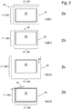
- a two-dimensional part of a robot arm (henceforth referred to as a robot arm) is shown as part of a kinematics 1, here a serial kinematics, the dashed lines describing the spatial boundary of the robot arm 1.
- the kinematics 1, or a part thereof, according to the invention with zero-dimensional (0d) or one-dimensional (1 d) objects, ie with a dimension D ⁇ 2, subsequently modeled as kinematics objects.
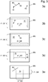
- the robot arm 1 by three point-shaped (0d) Kinematic objects K1, K2, K3, which in this case represent the hinge hubs of the robot arm 1 described.
- linear (1d) kinematic objects K4 are modeled, as in Fig.1 represented by the connecting line between the first point-shaped kinematic object K1 and the second point-shaped kinematic object K2.
- a line-shaped (1d) kinematic object K4 preferably connects two punctiform (0d) kinematic objects K1, K2 or K2, K3.
- the punctiform modeled kinematics objects K1, K2, K3 are considered in Figure 2d the linear kinematics object K4.
- the extension to a wireframe model is optional, as is a possible parameterization of the line spacing of two point-shaped kinematics objects K1, K2, K3. This parameterization and the extension to a wireframe model can be performed separately for each kinematic object K1, K2, K3, K4.
- a predetermined security area SS can be seen as monitoring area S.
- the predetermined security area SS results for example from the site and the environment of the kinematics 1 on site and is defined in advance, or can be assumed to be predetermined.
- a safety function of a kinematics 1 ensures that the kinematics 1 (or a part thereof) does not penetrate into the safety area SS or leaves a defined working area WS of the kinematics 1.
- the safety function is implemented, for example, in the control of the kinematics 1, but can also supplement the control of the kinematics 1 as an independent module.
- the security area SS represents a rectangle with the side lengths r1, r2, or half the side lengths r1 / 2, r2 / 2.
- the security area SS could, of course, also be defined in three dimensions.
- the kinematics 1, or a part thereof would be modeled as a three-dimensional object or a sum of three-dimensional objects, whereby a section of the object or objects would have to be calculated with the safety area.
- this review is very computationally intensive.
- the kinematics 1 is modeled as a number of kinematics objects K1, K2, K3, K4, each having a dimension smaller than two (D ⁇ 2), ie, for example in the form of a wireframe model.
- D ⁇ 2 dimension smaller than two
- the position and position of the kinematics objects K1, K2, K3, K4 in space always results clearly from the known geometry and movement the kinematics 1 and can therefore be assumed to be known.
- the safety function is generally integrated in the control of the kinematics 1, or at least is connected to it, the safety function can always access the current positions and positions of the kinematics objects K1, K2, K3, K4.
- a defined or parameterizable geometric parameter P1, P2, P3, P4 is now used for each kinematics object K1, K2, K3, K4 and the prescribed safety area SS is thereby changed.
- the parameters P1, P2, P3, P4 each use a maximum diameter of the respective part of the kinematics 1 on the number of kinematics objects K1, K2, K3, K4 (the articulated hubs or a part of the robot arm).
- the kinematics 1 (or a part thereof) is "reduced" by the modeling, which is expressed by the parameters P1, P2, P3, P4.
- the security area SS / work area WS is enlarged / reduced in dependence on this parameter P1, P2, P3, P4, the modeling of the kinematics 1 in the form of kinematics objects K1, K2, K3, K4 can be compensated for the realization of the safety function " become.
- the geometric parameters P1, P2, P3, P4 can, for example, follow from a stored allocation table which can be parameterized in advance on the basis of the known geometry of the kinematics 1.
- a first, second and third distance d1, d2, d3, d4 is calculated or derived from the geometrical parameter P1, P2, P3, P4 (here, for example, a diameter).
- the parameter P1, P2, P3, P4 in a simple embodiment also directly correspond to the respective distance d1, d2, d3, d4, optionally with a predetermined safety margin.
- the distance d1, d2, d3 d4 then again results from the parameter of the diameter via a relationship, for example by the distance d1, d2, d3 d4 corresponding to half the diameter.
- the distance d1, d2, d3, d4 changes for each kinematic object K1, K2, K3, K4 at least one geometric size G (here half the side lengths r1 / 2, r2 / 2) of the security area SS and thus leads to the changed security areas S1, S2, S3, S4.
- the geometric size G in the form of half the side lengths r1 / 2, r2 / 2 (in Fig.2 not explicitly drawn for clarity) by the distance d1, d2, d3, d4 is changed, whereby the rectangle is changed on each side by twice the distance 2 * d1, 2 * d2, 2 * d3, 2 * d4.
- the distance d1, d2, d3, d4 can therefore be derived as desired from the parameter P1, P2, P3, P4 as required.
- the geometrical variable G to be changed can be selected, here for example half the side lengths r1 / 2, r2 / 2.
- the security area SS is changed individually for each modeled kinematics object K1, K2, K3, K4, and each modeled kinematics object K1, K2, K3, K4 is assigned its own changed monitoring area S1, S2, S3, S4 (here security area).
- S1, S2, S3, S4 here security area
- each monitored, modeled kinematic object K1, K2, K3, K4 in space is checked for the safety function in relation to the respectively assigned modified monitoring area S1, S2, S3, S4.
- a modeled kinematics object K1, K2, K3, K4 in the changed monitoring area S1, S2, S3, S4 the monitored surveillance area of the kinematics 1 (in this case the security area SS) is violated, as shown in FIG Figure 2c for the third kinematics object K3 in conjunction with the third modified monitoring area S3 and in Fig. 2d for the fourth kinematic object K4 in conjunction with the fourth modified monitoring area S4.
- a plurality of distances d1, d2, d3, d4 per kinematics object K1, K2, K3, K4 can also be calculated for the monitoring area S, for example in the case of a rectangular monitoring area S the side lengths r1, r2 or half the side lengths r1 / 2 , r2 / 2, to change differently.
- the surveillance area S may represent a line (dimension one), or a body (dimension three) instead of the area (dimension two).
- the position of the number of kinematics objects K1, K2, K3, K4 must also be checked in relation to the monitoring area S, for example in the form of a section.
- an analogous method for a work area WS is shown as monitoring area S.
- the work area WS defines an area which may not be left by the kinematics 1 or a part thereof. Therefore, the distances d1, d2, d3, d4 decrease the at least one geometric variable G, ie half the side lengths r1 / 2, r2 / 2 (in Figure 3 for the sake of clarity not explicitly drawn) in the illustrated embodiment.
- each monitored modeled kinematic object K1, K2, K3, K4 in relation to the respective changed monitoring area S1, S2, S3, S4 is analogous to the security area SS in Fig.2
- a modeled kinematic object K1, K2, K3, K4 lies outside the changed monitoring area S1, S2, S3, S4, as shown in FIG 3 d for the third kinematics object K3 in relation to the changed monitoring area S3 and in 3E for the fourth kinematics object K4 in relation to the changed monitoring area S4 is the case.
- each kinematics object K1, K2, K3, K4 or a plurality of kinematics objects K1, K2, K3, K4 can have their own assigned monitoring area S.
- the associated monitoring area S for the respective kinematics object K1, K2, K3, K4 is changed and checked for infringement.
Landscapes
- Engineering & Computer Science (AREA)
- Robotics (AREA)
- Mechanical Engineering (AREA)
- Manipulator (AREA)
- Radar Systems Or Details Thereof (AREA)
Applications Claiming Priority (1)
| Application Number | Priority Date | Filing Date | Title |
|---|---|---|---|
| ATA50256/2016A AT518498B1 (de) | 2016-03-29 | 2016-03-29 | Positionsüberwachung einer Kinematik |
Publications (3)
| Publication Number | Publication Date |
|---|---|
| EP3225366A2 true EP3225366A2 (fr) | 2017-10-04 |
| EP3225366A3 EP3225366A3 (fr) | 2017-12-13 |
| EP3225366B1 EP3225366B1 (fr) | 2023-04-19 |
Family
ID=58448429
Family Applications (1)
| Application Number | Title | Priority Date | Filing Date |
|---|---|---|---|
| EP17163226.8A Active EP3225366B1 (fr) | 2016-03-29 | 2017-03-28 | Surveillance de la position d'un système cinématique |
Country Status (4)
| Country | Link |
|---|---|
| US (1) | US11279034B2 (fr) |
| EP (1) | EP3225366B1 (fr) |
| AT (1) | AT518498B1 (fr) |
| CA (1) | CA2962670A1 (fr) |
Cited By (3)
| Publication number | Priority date | Publication date | Assignee | Title |
|---|---|---|---|---|
| CN108115689A (zh) * | 2017-12-31 | 2018-06-05 | 芜湖哈特机器人产业技术研究院有限公司 | 一种机器人灵活性分析方法 |
| CN109834708A (zh) * | 2017-11-28 | 2019-06-04 | 发那科株式会社 | 限制机器人速度的控制装置 |
| CN110561417A (zh) * | 2019-08-05 | 2019-12-13 | 华中科技大学 | 一种多智能体无碰撞轨迹规划方法 |
Families Citing this family (1)
| Publication number | Priority date | Publication date | Assignee | Title |
|---|---|---|---|---|
| EP4365734A1 (fr) * | 2022-09-22 | 2024-05-08 | Contemporary Amperex Technology Co., Limited | Procédé et appareil de création d'objets de paire cinématique, et support de stockage |
Family Cites Families (10)
| Publication number | Priority date | Publication date | Assignee | Title |
|---|---|---|---|---|
| SE456048B (sv) * | 1982-02-24 | 1988-08-29 | Philips Norden Ab | Sett och anordning for att bestemma kollisionsrisken for tva inbordes rorliga kroppar |
| US5056031A (en) * | 1988-11-12 | 1991-10-08 | Kabushiki Kaisha Toyota Chuo Kenyusho | Apparatus for detecting the collision of moving objects |
| US5347459A (en) | 1993-03-17 | 1994-09-13 | National Research Council Of Canada | Real time collision detection |
| JPH0736519A (ja) * | 1993-07-23 | 1995-02-07 | Kobe Steel Ltd | ロボットのニアミスチェック方法 |
| JP3975959B2 (ja) | 2003-04-23 | 2007-09-12 | トヨタ自動車株式会社 | ロボット動作規制方法とその装置およびそれを備えたロボット |
| KR100663473B1 (ko) | 2005-10-14 | 2007-01-02 | 삼성전자주식회사 | Dmb 수신 단말기에서의 서비스 링킹을 통한 예약 녹화방법 |
| DE602006012485D1 (de) * | 2006-09-14 | 2010-04-08 | Abb Research Ltd | Verfahren und Vorrichtung zur Vermeidung von Kollisionen zwischen einem Industrieroboter und einem Objekt |
| DE102007037077B4 (de) | 2007-08-06 | 2019-02-21 | Kuka Roboter Gmbh | Verfahren zur Einhaltung von Arbeitsraumgrenzen eines Arbeitsmittels eines Roboters |
| EP3055744B1 (fr) * | 2013-10-07 | 2018-06-13 | ABB Schweiz AG | Procédé et dispositif permettant de vérifier un ou plusieurs volume(s) de sécurité pour une unité mécanique mobile |
| US9452531B2 (en) * | 2014-02-04 | 2016-09-27 | Microsoft Technology Licensing, Llc | Controlling a robot in the presence of a moving object |
-
2016
- 2016-03-29 AT ATA50256/2016A patent/AT518498B1/de not_active IP Right Cessation
-
2017
- 2017-03-28 US US15/471,265 patent/US11279034B2/en active Active
- 2017-03-28 CA CA2962670A patent/CA2962670A1/fr not_active Abandoned
- 2017-03-28 EP EP17163226.8A patent/EP3225366B1/fr active Active
Cited By (5)
| Publication number | Priority date | Publication date | Assignee | Title |
|---|---|---|---|---|
| CN109834708A (zh) * | 2017-11-28 | 2019-06-04 | 发那科株式会社 | 限制机器人速度的控制装置 |
| CN109834708B (zh) * | 2017-11-28 | 2020-12-29 | 发那科株式会社 | 限制机器人速度的控制装置 |
| CN108115689A (zh) * | 2017-12-31 | 2018-06-05 | 芜湖哈特机器人产业技术研究院有限公司 | 一种机器人灵活性分析方法 |
| CN110561417A (zh) * | 2019-08-05 | 2019-12-13 | 华中科技大学 | 一种多智能体无碰撞轨迹规划方法 |
| CN110561417B (zh) * | 2019-08-05 | 2021-03-26 | 华中科技大学 | 一种多智能体无碰撞轨迹规划方法 |
Also Published As
| Publication number | Publication date |
|---|---|
| EP3225366B1 (fr) | 2023-04-19 |
| EP3225366A3 (fr) | 2017-12-13 |
| US20170282370A1 (en) | 2017-10-05 |
| AT518498A1 (de) | 2017-10-15 |
| US11279034B2 (en) | 2022-03-22 |
| AT518498B1 (de) | 2018-09-15 |
| CA2962670A1 (fr) | 2017-09-29 |
Similar Documents
| Publication | Publication Date | Title |
|---|---|---|
| EP1906281B1 (fr) | Procédé et système pour la conception et la vérification de zones de sécurité d'un robot industriel | |
| EP3532254B1 (fr) | Procédé de planification de déplacement sans collision | |
| DE112017002498B4 (de) | Robotervorgang-auswertungseinrichtung, robotervorgang-auswertungsverfahren und robotersystem | |
| EP3225366B1 (fr) | Surveillance de la position d'un système cinématique | |
| DE102007059480B4 (de) | Verfahren und Vorrichtung zur Posenüberwachung eines Manipulators | |
| DE102010023736B4 (de) | Robotersystem mit Problemerkennungsfunktion | |
| DE102006007623B4 (de) | Roboter mit einer Steuereinheit zum Steuern einer Bewegung zwischen einer Anfangspose und einer Endpose | |
| EP2964428B1 (fr) | Procédé de vérification de la trajectoire d'un robot | |
| EP3556521B1 (fr) | Surveillance de la distance de freinage d'une cinématique | |
| DE102007037077B4 (de) | Verfahren zur Einhaltung von Arbeitsraumgrenzen eines Arbeitsmittels eines Roboters | |
| EP1722935A1 (fr) | Procede de calibrage d'un point de fonctionnement d'outils pour robots industriels | |
| DE102014224193B9 (de) | Verfahren und Vorrichtung zur Fehlerhandhabung eines Roboters | |
| EP3670110A1 (fr) | Procédé et dispositif d'estimation du couple | |
| DE102017222057A1 (de) | Robotersystem | |
| DE102013110901A1 (de) | MRK Planungstechnologie | |
| EP3037219B1 (fr) | Robot sur ayant des variables de progression de glissiere | |
| DE102015009815A1 (de) | Verfahren zum Steuern eines mobilen redundanten Roboters | |
| DE102020203636A1 (de) | Ermittlung von Sicherheitsbereichen um eine automatisiert arbeitende Maschine | |
| DE102012022190B4 (de) | Inverse Kinematik | |
| EP3323565B1 (fr) | Procédé et dispositif de mise en service d'un système multiaxial | |
| DE102013110905A1 (de) | MRK Planungs- und Überwachungstechnologie | |
| EP3819088A1 (fr) | Procédé de détermination d'une zone de sécurité et de planification de trajectoire pour robots | |
| EP4056331A1 (fr) | Fonctionnement sécurisé d'une cinématique à axes multiples | |
| DE102017116788B4 (de) | Roboter-Steuerungsvorrichtung und Verfahren zur Steuerung derselben | |
| EP3569367A1 (fr) | Détermination d'un mouvement d'un dispositif assistée par ordinateur |
Legal Events
| Date | Code | Title | Description |
|---|---|---|---|
| PUAI | Public reference made under article 153(3) epc to a published international application that has entered the european phase |
Free format text: ORIGINAL CODE: 0009012 |
|
| STAA | Information on the status of an ep patent application or granted ep patent |
Free format text: STATUS: THE APPLICATION HAS BEEN PUBLISHED |
|
| AK | Designated contracting states |
Kind code of ref document: A2 Designated state(s): AL AT BE BG CH CY CZ DE DK EE ES FI FR GB GR HR HU IE IS IT LI LT LU LV MC MK MT NL NO PL PT RO RS SE SI SK SM TR |
|
| AX | Request for extension of the european patent |
Extension state: BA ME |
|
| PUAL | Search report despatched |
Free format text: ORIGINAL CODE: 0009013 |
|
| RAP1 | Party data changed (applicant data changed or rights of an application transferred) |
Owner name: B&R INDUSTRIAL AUTOMATION GMBH |
|
| AK | Designated contracting states |
Kind code of ref document: A3 Designated state(s): AL AT BE BG CH CY CZ DE DK EE ES FI FR GB GR HR HU IE IS IT LI LT LU LV MC MK MT NL NO PL PT RO RS SE SI SK SM TR |
|
| AX | Request for extension of the european patent |
Extension state: BA ME |
|
| RIC1 | Information provided on ipc code assigned before grant |
Ipc: B25J 9/16 20060101AFI20171107BHEP |
|
| STAA | Information on the status of an ep patent application or granted ep patent |
Free format text: STATUS: REQUEST FOR EXAMINATION WAS MADE |
|
| 17P | Request for examination filed |
Effective date: 20180608 |
|
| RBV | Designated contracting states (corrected) |
Designated state(s): AL AT BE BG CH CY CZ DE DK EE ES FI FR GB GR HR HU IE IS IT LI LT LU LV MC MK MT NL NO PL PT RO RS SE SI SK SM TR |
|
| STAA | Information on the status of an ep patent application or granted ep patent |
Free format text: STATUS: EXAMINATION IS IN PROGRESS |
|
| STAA | Information on the status of an ep patent application or granted ep patent |
Free format text: STATUS: EXAMINATION IS IN PROGRESS |
|
| 17Q | First examination report despatched |
Effective date: 20201216 |
|
| STAA | Information on the status of an ep patent application or granted ep patent |
Free format text: STATUS: EXAMINATION IS IN PROGRESS |
|
| GRAP | Despatch of communication of intention to grant a patent |
Free format text: ORIGINAL CODE: EPIDOSNIGR1 |
|
| STAA | Information on the status of an ep patent application or granted ep patent |
Free format text: STATUS: GRANT OF PATENT IS INTENDED |
|
| INTG | Intention to grant announced |
Effective date: 20221130 |
|
| GRAS | Grant fee paid |
Free format text: ORIGINAL CODE: EPIDOSNIGR3 |
|
| GRAA | (expected) grant |
Free format text: ORIGINAL CODE: 0009210 |
|
| STAA | Information on the status of an ep patent application or granted ep patent |
Free format text: STATUS: THE PATENT HAS BEEN GRANTED |
|
| AK | Designated contracting states |
Kind code of ref document: B1 Designated state(s): AL AT BE BG CH CY CZ DE DK EE ES FI FR GB GR HR HU IE IS IT LI LT LU LV MC MK MT NL NO PL PT RO RS SE SI SK SM TR |
|
| REG | Reference to a national code |
Ref country code: GB Ref legal event code: FG4D Free format text: NOT ENGLISH |
|
| REG | Reference to a national code |
Ref country code: DE Ref legal event code: R096 Ref document number: 502017014628 Country of ref document: DE |
|
| REG | Reference to a national code |
Ref country code: CH Ref legal event code: EP |
|
| REG | Reference to a national code |
Ref country code: IE Ref legal event code: FG4D Free format text: LANGUAGE OF EP DOCUMENT: GERMAN |
|
| REG | Reference to a national code |
Ref country code: AT Ref legal event code: REF Ref document number: 1560839 Country of ref document: AT Kind code of ref document: T Effective date: 20230515 |
|
| P01 | Opt-out of the competence of the unified patent court (upc) registered |
Effective date: 20230615 |
|
| REG | Reference to a national code |
Ref country code: LT Ref legal event code: MG9D |
|
| REG | Reference to a national code |
Ref country code: NL Ref legal event code: MP Effective date: 20230419 |
|
| PG25 | Lapsed in a contracting state [announced via postgrant information from national office to epo] |
Ref country code: NL Free format text: LAPSE BECAUSE OF FAILURE TO SUBMIT A TRANSLATION OF THE DESCRIPTION OR TO PAY THE FEE WITHIN THE PRESCRIBED TIME-LIMIT Effective date: 20230419 |
|
| PG25 | Lapsed in a contracting state [announced via postgrant information from national office to epo] |
Ref country code: SE Free format text: LAPSE BECAUSE OF FAILURE TO SUBMIT A TRANSLATION OF THE DESCRIPTION OR TO PAY THE FEE WITHIN THE PRESCRIBED TIME-LIMIT Effective date: 20230419 Ref country code: PT Free format text: LAPSE BECAUSE OF FAILURE TO SUBMIT A TRANSLATION OF THE DESCRIPTION OR TO PAY THE FEE WITHIN THE PRESCRIBED TIME-LIMIT Effective date: 20230821 Ref country code: NO Free format text: LAPSE BECAUSE OF FAILURE TO SUBMIT A TRANSLATION OF THE DESCRIPTION OR TO PAY THE FEE WITHIN THE PRESCRIBED TIME-LIMIT Effective date: 20230719 Ref country code: ES Free format text: LAPSE BECAUSE OF FAILURE TO SUBMIT A TRANSLATION OF THE DESCRIPTION OR TO PAY THE FEE WITHIN THE PRESCRIBED TIME-LIMIT Effective date: 20230419 |
|
| PG25 | Lapsed in a contracting state [announced via postgrant information from national office to epo] |
Ref country code: RS Free format text: LAPSE BECAUSE OF FAILURE TO SUBMIT A TRANSLATION OF THE DESCRIPTION OR TO PAY THE FEE WITHIN THE PRESCRIBED TIME-LIMIT Effective date: 20230419 Ref country code: PL Free format text: LAPSE BECAUSE OF FAILURE TO SUBMIT A TRANSLATION OF THE DESCRIPTION OR TO PAY THE FEE WITHIN THE PRESCRIBED TIME-LIMIT Effective date: 20230419 Ref country code: LV Free format text: LAPSE BECAUSE OF FAILURE TO SUBMIT A TRANSLATION OF THE DESCRIPTION OR TO PAY THE FEE WITHIN THE PRESCRIBED TIME-LIMIT Effective date: 20230419 Ref country code: LT Free format text: LAPSE BECAUSE OF FAILURE TO SUBMIT A TRANSLATION OF THE DESCRIPTION OR TO PAY THE FEE WITHIN THE PRESCRIBED TIME-LIMIT Effective date: 20230419 Ref country code: IS Free format text: LAPSE BECAUSE OF FAILURE TO SUBMIT A TRANSLATION OF THE DESCRIPTION OR TO PAY THE FEE WITHIN THE PRESCRIBED TIME-LIMIT Effective date: 20230819 Ref country code: HR Free format text: LAPSE BECAUSE OF FAILURE TO SUBMIT A TRANSLATION OF THE DESCRIPTION OR TO PAY THE FEE WITHIN THE PRESCRIBED TIME-LIMIT Effective date: 20230419 Ref country code: GR Free format text: LAPSE BECAUSE OF FAILURE TO SUBMIT A TRANSLATION OF THE DESCRIPTION OR TO PAY THE FEE WITHIN THE PRESCRIBED TIME-LIMIT Effective date: 20230720 Ref country code: AL Free format text: LAPSE BECAUSE OF FAILURE TO SUBMIT A TRANSLATION OF THE DESCRIPTION OR TO PAY THE FEE WITHIN THE PRESCRIBED TIME-LIMIT Effective date: 20230419 |
|
| PG25 | Lapsed in a contracting state [announced via postgrant information from national office to epo] |
Ref country code: FI Free format text: LAPSE BECAUSE OF FAILURE TO SUBMIT A TRANSLATION OF THE DESCRIPTION OR TO PAY THE FEE WITHIN THE PRESCRIBED TIME-LIMIT Effective date: 20230419 |
|
| PG25 | Lapsed in a contracting state [announced via postgrant information from national office to epo] |
Ref country code: SK Free format text: LAPSE BECAUSE OF FAILURE TO SUBMIT A TRANSLATION OF THE DESCRIPTION OR TO PAY THE FEE WITHIN THE PRESCRIBED TIME-LIMIT Effective date: 20230419 |
|
| REG | Reference to a national code |
Ref country code: DE Ref legal event code: R097 Ref document number: 502017014628 Country of ref document: DE |
|
| PG25 | Lapsed in a contracting state [announced via postgrant information from national office to epo] |
Ref country code: SM Free format text: LAPSE BECAUSE OF FAILURE TO SUBMIT A TRANSLATION OF THE DESCRIPTION OR TO PAY THE FEE WITHIN THE PRESCRIBED TIME-LIMIT Effective date: 20230419 Ref country code: SK Free format text: LAPSE BECAUSE OF FAILURE TO SUBMIT A TRANSLATION OF THE DESCRIPTION OR TO PAY THE FEE WITHIN THE PRESCRIBED TIME-LIMIT Effective date: 20230419 Ref country code: RO Free format text: LAPSE BECAUSE OF FAILURE TO SUBMIT A TRANSLATION OF THE DESCRIPTION OR TO PAY THE FEE WITHIN THE PRESCRIBED TIME-LIMIT Effective date: 20230419 Ref country code: EE Free format text: LAPSE BECAUSE OF FAILURE TO SUBMIT A TRANSLATION OF THE DESCRIPTION OR TO PAY THE FEE WITHIN THE PRESCRIBED TIME-LIMIT Effective date: 20230419 Ref country code: DK Free format text: LAPSE BECAUSE OF FAILURE TO SUBMIT A TRANSLATION OF THE DESCRIPTION OR TO PAY THE FEE WITHIN THE PRESCRIBED TIME-LIMIT Effective date: 20230419 Ref country code: CZ Free format text: LAPSE BECAUSE OF FAILURE TO SUBMIT A TRANSLATION OF THE DESCRIPTION OR TO PAY THE FEE WITHIN THE PRESCRIBED TIME-LIMIT Effective date: 20230419 |
|
| PLBE | No opposition filed within time limit |
Free format text: ORIGINAL CODE: 0009261 |
|
| STAA | Information on the status of an ep patent application or granted ep patent |
Free format text: STATUS: NO OPPOSITION FILED WITHIN TIME LIMIT |
|
| 26N | No opposition filed |
Effective date: 20240122 |
|
| PGFP | Annual fee paid to national office [announced via postgrant information from national office to epo] |
Ref country code: DE Payment date: 20240129 Year of fee payment: 8 |
|
| PG25 | Lapsed in a contracting state [announced via postgrant information from national office to epo] |
Ref country code: SI Free format text: LAPSE BECAUSE OF FAILURE TO SUBMIT A TRANSLATION OF THE DESCRIPTION OR TO PAY THE FEE WITHIN THE PRESCRIBED TIME-LIMIT Effective date: 20230419 |