EP3225050B1 - Techniques for managing inter-radio access technology handovers for high gain user equipment - Google Patents
Techniques for managing inter-radio access technology handovers for high gain user equipment Download PDFInfo
- Publication number
- EP3225050B1 EP3225050B1 EP15813959.2A EP15813959A EP3225050B1 EP 3225050 B1 EP3225050 B1 EP 3225050B1 EP 15813959 A EP15813959 A EP 15813959A EP 3225050 B1 EP3225050 B1 EP 3225050B1
- Authority
- EP
- European Patent Office
- Prior art keywords
- power
- base station
- parameter
- offset
- quality
- Prior art date
- Legal status (The legal status is an assumption and is not a legal conclusion. Google has not performed a legal analysis and makes no representation as to the accuracy of the status listed.)
- Active
Links
- 238000000034 method Methods 0.000 title claims description 79
- 238000005516 engineering process Methods 0.000 title claims description 30
- 238000005259 measurement Methods 0.000 claims description 128
- 230000006854 communication Effects 0.000 claims description 122
- 238000004891 communication Methods 0.000 claims description 122
- 230000005540 biological transmission Effects 0.000 description 21
- 238000012545 processing Methods 0.000 description 16
- 230000008569 process Effects 0.000 description 13
- 230000001413 cellular effect Effects 0.000 description 12
- 238000010586 diagram Methods 0.000 description 12
- 230000001960 triggered effect Effects 0.000 description 11
- 230000006870 function Effects 0.000 description 10
- 238000001228 spectrum Methods 0.000 description 8
- 238000007620 mathematical function Methods 0.000 description 6
- 230000008901 benefit Effects 0.000 description 5
- 239000000969 carrier Substances 0.000 description 5
- 230000001360 synchronised effect Effects 0.000 description 4
- 241000700159 Rattus Species 0.000 description 3
- 230000002776 aggregation Effects 0.000 description 3
- 238000004220 aggregation Methods 0.000 description 3
- 230000003247 decreasing effect Effects 0.000 description 3
- 230000015556 catabolic process Effects 0.000 description 2
- 238000006731 degradation reaction Methods 0.000 description 2
- 230000001419 dependent effect Effects 0.000 description 2
- 238000013461 design Methods 0.000 description 2
- 230000007774 longterm Effects 0.000 description 2
- 238000000120 microwave digestion Methods 0.000 description 2
- 238000012986 modification Methods 0.000 description 2
- 230000004048 modification Effects 0.000 description 2
- 230000011664 signaling Effects 0.000 description 2
- 238000013459 approach Methods 0.000 description 1
- 238000003491 array Methods 0.000 description 1
- 238000013475 authorization Methods 0.000 description 1
- 230000007175 bidirectional communication Effects 0.000 description 1
- 230000009028 cell transition Effects 0.000 description 1
- 239000003795 chemical substances by application Substances 0.000 description 1
- 238000010276 construction Methods 0.000 description 1
- 238000001514 detection method Methods 0.000 description 1
- 239000000284 extract Substances 0.000 description 1
- 230000000977 initiatory effect Effects 0.000 description 1
- 238000012423 maintenance Methods 0.000 description 1
- 230000008520 organization Effects 0.000 description 1
- 230000002093 peripheral effect Effects 0.000 description 1
- 230000002441 reversible effect Effects 0.000 description 1
- 230000011218 segmentation Effects 0.000 description 1
- 230000003595 spectral effect Effects 0.000 description 1
Images


Classifications
-
- H—ELECTRICITY
- H04—ELECTRIC COMMUNICATION TECHNIQUE
- H04W—WIRELESS COMMUNICATION NETWORKS
- H04W36/00—Hand-off or reselection arrangements
- H04W36/0005—Control or signalling for completing the hand-off
- H04W36/0083—Determination of parameters used for hand-off, e.g. generation or modification of neighbour cell lists
- H04W36/0085—Hand-off measurements
- H04W36/0094—Definition of hand-off measurement parameters
-
- H—ELECTRICITY
- H04—ELECTRIC COMMUNICATION TECHNIQUE
- H04W—WIRELESS COMMUNICATION NETWORKS
- H04W36/00—Hand-off or reselection arrangements
- H04W36/14—Reselecting a network or an air interface
- H04W36/144—Reselecting a network or an air interface over a different radio air interface technology
- H04W36/1446—Reselecting a network or an air interface over a different radio air interface technology wherein at least one of the networks is unlicensed
-
- H—ELECTRICITY
- H04—ELECTRIC COMMUNICATION TECHNIQUE
- H04W—WIRELESS COMMUNICATION NETWORKS
- H04W24/00—Supervisory, monitoring or testing arrangements
- H04W24/10—Scheduling measurement reports ; Arrangements for measurement reports
-
- H—ELECTRICITY
- H04—ELECTRIC COMMUNICATION TECHNIQUE
- H04W—WIRELESS COMMUNICATION NETWORKS
- H04W36/00—Hand-off or reselection arrangements
- H04W36/14—Reselecting a network or an air interface
Definitions
- the present disclosure relates generally to communication systems, and more particularly, to techniques for managing inter-radio access technology handovers for high gain user equipment.
- Wireless communication systems are widely deployed to provide various telecommunication services such as telephony, video, data, messaging, and broadcasts.
- Typical wireless communication systems may employ multiple-access technologies capable of supporting communication with multiple users by sharing available system resources (e.g., bandwidth, transmit power).
- multiple-access technologies include code division multiple access (CDMA) systems, time division multiple access (TDMA) systems, frequency division multiple access (FDMA) systems, orthogonal frequency division multiple access (OFDMA) systems, single-carrier frequency division multiple access (SC-FDMA) systems, and time division synchronous code division multiple access (TD-SCDMA) systems.
- CDMA code division multiple access
- TDMA time division multiple access
- FDMA frequency division multiple access
- OFDMA orthogonal frequency division multiple access
- SC-FDMA single-carrier frequency division multiple access
- TD-SCDMA time division synchronous code division multiple access
- LTE Long Term Evolution
- UMTS Universal Mobile Telecommunications System
- 3GPP Third Generation Partnership Project
- LTE is designed to better support mobile broadband Internet access by improving spectral efficiency, lowering costs, improving services, making use of new spectrum, and better integrating with other open standards using OFDMA on the downlink (DL), SC-FDMA on the uplink (UL), and multiple-input multiple-output (MIMO) antenna technology.
- US 2014/098693 A1 describes a method for triggering cell transition in an uplink power limited condition
- US 2011/0116395 A1 discloses a radio communication terminal performing a technique of handover which is capable of maintaining a high communication rate communication environment over multiple radio communication systems.
- EP 2 355 579 A1 describes optimized handover configuration based on power measurement reports.
- a UE is informed of a cell specific offset to be applied to the measured received power in a given cell before reporting, which is typically expressed as RSRP in LTE.
- the individual measuring power offsets are link-quality dependent, i.e., dependent on a prevailing link quality between a UE and at least one of the serving cell and the respective neighboring cell.
- the techniques described may include memory and at least one processor, coupled to the memory, configured to determine a power parameter associated with communication using a first radio access technology (RAT).
- the at least one processor may be further configured to determine a quality parameter associated with the communication using the first RAT.
- the at least one processor may be further configured to apply, based on the quality parameter, an offset to the power parameter to form a modified power parameter.
- the at least one processor may be further configured to transmit a measurement report including the modified power parameter.
- RAT radio access technology
- the power parameter includes a reference signal received power.
- the quality parameter includes a reference signal received quality or a block error rate.
- the at least one processor is further configured to determine the offset based on the quality parameter.
- the at least one processor is configured to apply the offset further based on determination that a power gain satisfies a power gain threshold, and the at least one processor is further configured to determine the power gain and determine that the power gain satisfies the power gain threshold.
- the at least one processor is configured to apply, based on the quality parameter, the offset to the power parameter to form a modified power parameter by determining that the quality parameter satisfies a quality threshold and applying the offset to the power parameter when the quality parameter satisfies the quality threshold.
- the at least one processor is configured to apply the offset to the power parameter further based on determination that a second quality parameter satisfies a second quality threshold, the at least one processor further configured to determine that the second quality parameter satisfies the second quality threshold.
- the at least one processor is configured to transmit the measurement report based on determination that the modified power parameter satisfies a reporting threshold, the at least one processor further configured to determine that the modified power parameter satisfies the reporting threshold.
- the measurement report is transmitted to a serving base station in association with handover to a neighbor base station, the at least one processor further configured to receive the communication from the serving base station, wherein the serving base station associated with a first RAT and the neighbor base station associated with a second RAT.
- the method may include an operation for determining a power parameter associated with communication using a first RAT.
- the method may further include an operation for determining a quality parameter associated with the communication using the first RAT.
- the method may further include an operation for applying, based on the quality parameter, an offset to the power parameter to form a modified power parameter.
- the method may further include an operation for transmitting a measurement report including the modified power parameter.
- the method may be performed by a user equipment (UE).
- UE user equipment
- the power parameter may include a reference signal received power.
- the quality parameter includes a reference signal received quality or a block error rate.
- the method further includes an operation for determining the offset based on the quality parameter.
- the applying of the offset is further based on determining that a power gain satisfies a power gain threshold, and the method further includes operations for determining, by the UE, the power gain and determining, by the UE, that the power gain satisfies the power gain threshold.
- the applying, based on the quality parameter, the offset to the power parameter to form a modified power parameter includes determining that the quality parameter satisfies a quality threshold and applying the offset to the power parameter when the quality parameter satisfies the quality threshold.
- the applying the offset to the power parameter is further based on determining that a second quality parameter satisfies a second quality threshold, the method further includes an operation for determining that the second quality parameter satisfies the second quality threshold.
- the transmitting the measurement report is based on determining that the modified power parameter satisfies a reporting threshold, the method further includes an operation for determining that the modified power parameter satisfies the reporting threshold.
- the measurement report is transmitted to a serving base station in association with handover to a neighbor base station, the method further includes an operation for receiving the communication from the serving base station, the serving base station associated with a first RAT and the neighbor base station associated with a second RAT.
- the first RAT is different from the second RAT.
- the computer-readable medium may store computer executable code for wireless communication, including code for determining a power parameter associated with communication using a first RAT.
- the computer-readable medium may further include code for determining a quality parameter associated with the communication using the first RAT.
- the computer-readable medium may further include code for applying, based on the quality parameter, an offset to the power parameter to form a modified power parameter.
- the computer-readable medium may further include code for transmitting a measurement report including the modified power parameter.
- the power parameter includes a reference signal received power.
- the quality parameter includes a reference signal received quality or a block error rate.
- the code further includes code for determining the offset based on the quality parameter.
- the applying of the offset is further based on determining that a power gain satisfies a power gain threshold, and the code further includes code for determining, by the UE, the power gain and determining, by the UE, that the power gain satisfies the power gain threshold.
- the applying, based on the quality parameter, the offset to the power parameter to form a modified power parameter includes determining that the quality parameter satisfies a quality threshold and applying the offset to the power parameter when the quality parameter satisfies the quality threshold.
- the applying the offset to the power parameter is further based on determining that a second quality parameter satisfies a second quality threshold, the code further includes code for determining that the second quality parameter satisfies the second quality threshold.
- the transmitting the measurement report is based on determining that the modified power parameter satisfies a reporting threshold, the code further includes code for determining that the modified power parameter satisfies the reporting threshold.
- the measurement report is transmitted to a serving base station in association with handover to a neighbor base station
- the code further includes code for receiving the communication from the serving base station, the serving base station associated with a first RAT and the neighbor base station associated with a second RAT.
- the first RAT is different from the second RAT.
- the present disclosure describes a method for wireless communication, including determining, by a UE, a power parameter associated with a communication using a first RAT.
- the method may further include determining, by the UE, a quality parameter associated with the communication using the first RAT.
- the method may further include applying, by the UE, an offset to the power parameter, to form a modified power parameter, based on the quality parameter and based on a determination that a power gain of the UE satisfies a power gain threshold.
- the method may further include providing, by the UE, a measurement report, that includes the modified power parameter, for a handover from the first RAT to a second RAT.
- the power parameter represents a reference signal received power (RSRP).
- RSRP reference signal received power
- the quality parameter represents at least one of a reference signal received quality (RSRQ) or a block error rate (BLER).
- the first RAT is a fourth generation (4G) RAT.
- the second RAT is a third generation (3G) RAT.
- the method may further include calculating the offset, using the quality parameter, to form a calculated offset.
- applying the offset to the power parameter includes applying the calculated offset to the power parameter.
- the offset is inversely proportional to the quality parameter.
- applying the offset to the power parameter includes subtracting the offset from the power parameter.
- the method further includes determining the power gain.
- the method further includes determining that the power gain satisfies the power gain threshold. In an aspect, applying the offset to the power parameter includes applying the offset to the power parameter based on determining that the power gain satisfies the power gain threshold. In an aspect, the method further includes calculating the offset based on the power gain. In an aspect, applying the offset to the power parameter includes applying the offset to the power parameter based on calculating the offset. In an aspect, the offset is proportional to the power gain. In an aspect, the method further includes determining that the quality parameter satisfies a quality threshold. In an aspect, applying the offset to the power parameter includes applying the offset to the power parameter based on determining that the quality parameter satisfies the quality threshold.
- the method further includes determining that a first quality parameter satisfies a first quality threshold. In an aspect, the method further includes determining that a second quality parameter satisfies a second quality threshold. In an aspect, applying the offset to the power parameter includes applying the offset to the power parameter based on determining that the first quality parameter satisfies the first quality threshold and determining that the second quality parameter satisfies the second quality threshold. In an aspect, the first quality parameter is different from the second quality parameter. In an aspect, the first quality threshold is different from the second quality threshold. In an aspect, the first quality parameter represents a RSRQ. In an aspect, the second quality parameter represents a BLER.
- the power parameter represents at least one of a RSRP, a received signal code power (RSCP), a ratio of a received energy per chip to an interference level (Ec/Io), or a received signal strength indicator (RSSI).
- the quality parameter represents at least one of a RSRQ, a BLER, or a signal to noise ratio (SINR).
- the first RAT includes one of a 4G RAT, a 3G RAT, a second generation (2G) RAT, or a Wi-Fi RAT and the second RAT includes a different one of the 4G RAT, the 3G RAT, the 2G RAT, or the Wi-Fi RAT.
- the method further includes determining that the modified power parameter satisfies a reporting threshold. In an aspect, providing the measurement report includes providing the measurement report based on determining that the modified power parameter satisfies the reporting threshold. In an aspect, the first RAT is different from the second RAT. In an aspect, the communication is received from a serving base station associated with the first RAT and the second RAT is associated with a neighbor base station. In an aspect, providing the measurement report includes providing the measurement report to the serving base station for the handover to the neighbor base station.
- a UE includes one or more processors to determine a power parameter associated with a communication using a first RAT.
- the one or more processors may determine a quality parameter associated with the communication using the first RAT.
- the one or more processors may apply an offset to the power parameter, to form a modified power parameter, based on the quality parameter and based on a determination that a power gain of the UE satisfies a power gain threshold.
- the one or more processors may provide a measurement report, that includes the modified power parameter, for a handover from the first RAT to a second RAT.
- the power parameter represents a RSRP.
- the quality parameter represents at least one of a RSRQ or a BLER.
- the first RAT is a 4G RAT and the second RAT is a 3G RAT.
- the one or more processors are further to calculate the offset, using the quality parameter, to form a calculated offset.
- the one or more processors, when applying the offset to the power parameter are further to apply the calculated offset to the power parameter.
- the offset is inversely proportional to the quality parameter.
- the one or more processors, when applying the offset to the power parameter are further to subtract the offset from the power parameter.
- the one or more processors are further to determine the power gain and determine that the power gain satisfies the power gain threshold.
- the one or more processors when applying the offset to the power parameter, are further to apply the offset to the power parameter based on determining that the power gain satisfies the power gain threshold. In an aspect, the one or more processors are further to calculate the offset based on the power gain. In an aspect, the one or more processors, when applying the offset to the power parameter, are further to apply the offset to the power parameter based on calculating the offset. In an aspect, the offset is proportional to the power gain. In an aspect, the one or more processors are further to determine that the quality parameter satisfies a quality threshold.
- the one or more processors when applying the offset to the power parameter, are further to apply the offset to the power parameter based on determining that the quality parameter satisfies the quality threshold. In an aspect, the one or more processors are further to determine that a first quality parameter satisfies a first quality threshold and determine that a second quality parameter satisfies a second quality threshold. In an aspect, the one or more processors, when applying the offset to the power parameter, are further to apply the offset to the power parameter based on determining that the first quality parameter satisfies the first quality threshold and determining that the second quality parameter satisfies the second quality threshold. In an aspect, the first quality parameter is different from the second quality parameter and the first quality threshold is different from the second quality threshold.
- the first quality parameter represents a RSRQ and the second quality parameter represents a BLER.
- the power parameter represents at least one of a RSRP, a RSCP, a Ec/Io, or a RSSI.
- the quality parameter represents at least one of a RSRQ, a BLER, or a SINR.
- the first RAT includes one of a 4G RAT, a 3G RAT, a 2G RAT, or a Wi-Fi RAT and the second RAT includes a different one of the 4G RAT, the 3G RAT, the 2G RAT, or the Wi-Fi RAT.
- the one or more processors are further to determine that the modified power parameter satisfies a reporting threshold and, when providing the measurement report, are further to provide the measurement report based on determining that the modified power parameter satisfies the reporting threshold.
- the first RAT is different from the second RAT.
- the communication is received from a serving base station associated with the first RAT and the second RAT is associated with a neighbor base station, and the one or more processors, when providing the measurement report, are further to provide the measurement report to the serving base station for the handover to the neighbor base station.
- a non-transitory computer-readable medium storing instructions for wireless communication.
- the instructions include, one or more instructions that, when executed by one or more processors of a UE, cause the one or more processors to determine a power parameter associated with a communication using a first radio access technology RAT; determine a quality parameter associated with the communication using the first RAT; apply an offset to the power parameter, to form a modified power parameter, based on the quality parameter and based on a determination that a power gain of the UE satisfies a power gain threshold; and provide a measurement report, that includes the modified power parameter, for a handover from the first RAT to a second RAT.
- the power parameter represents a RSRP.
- the quality parameter represents at least one of a RSRQ or a BLER.
- the first RAT is a 4G RAT and the second RAT is a 3G RAT.
- the one or more instructions when executed by the one or more processors, further cause the one or more processors to calculate the offset, using the quality parameter, to form a calculated offset; and the one or more instructions, that cause the one or more processors to apply the offset to the power parameter, further cause the one or more processors to apply the calculated offset to the power parameter.
- the offset is inversely proportional to the quality parameter.
- the one or more instructions, that cause the one or more processors to apply the offset to the power parameter further cause the one or more processors to subtract the offset from the power parameter.
- the one or more instructions when executed by the one or more processors, further cause the one or more processors to: determine the power gain; determine that the power gain satisfies the power gain threshold; and the one or more instructions, that cause the one or more processors to apply the offset to the power parameter, further cause the one or more processors to apply the offset to the power parameter based on determining that the power gain satisfies the power gain threshold.
- the one or more instructions when executed by the one or more processors, further cause the one or more processors to calculate the offset based on the power gain; and the one or more instructions, that cause the one or more processors to apply the offset to the power parameter, further cause the one or more processors to apply the offset to the power parameter based on calculating the offset.
- the offset is proportional to the power gain.
- the one or more instructions when executed by the one or more processors, further cause the one or more processors to determine that the quality parameter satisfies a quality threshold; and the one or more instructions, that cause the one or more processors to apply the offset to the power parameter, further cause the one or more processors to apply the offset to the power parameter based on determining that the quality parameter satisfies the quality threshold.
- the one or more instructions when executed by the one or more processors, further cause the one or more processors to determine that a first quality parameter satisfies a first quality threshold; determine that a second quality parameter satisfies a second quality threshold; and the one or more instructions, that cause the one or more processors to apply the offset to the power parameter, further cause the one or more processors to apply the offset to the power parameter based on determining that the first quality parameter satisfies the first quality threshold and determining that the second quality parameter satisfies the second quality threshold.
- the first quality parameter is different from the second quality parameter and the first quality threshold is different from the second quality threshold.
- the first quality parameter represents a RSRQ and the second quality parameter represents a BLER.
- the power parameter represents at least one of a RSRP, a RSCP, a Ec/Io, or a RSSI.
- the quality parameter represents at least one of a RSRQ, a BLER, or a SINR.
- the first RAT includes one of a 4G RAT, a 3G RAT, a 2G RAT, or a Wi-Fi RAT; and the second RAT includes a different one of the 4G RAT, the 3G RAT, the 2G RAT, or the Wi-Fi RAT.
- the one or more instructions when executed by the one or more processors, further cause the one or more processors to determine that the modified power parameter satisfies a reporting threshold; and the one or more instructions, that cause the one or more processors to provide the measurement report, further cause the one or more processors to provide the measurement report based on determining that the modified power parameter satisfies the reporting threshold.
- the first RAT is different from the second RAT.
- the communication is received from a serving base station associated with the first RAT and the second RAT is associated with a neighbor base station, and the one or more instructions, that cause the one or more processors to provide the measurement report, further cause the one or more processors to provide the measurement report to the serving base station for the handover to the neighbor base station.
- an apparatus for wireless communication includes means for determining a power parameter associated with a communication using a first radio access technology (RAT); means for determining a quality parameter associated with the communication using the first RAT; means for applying an offset to the power parameter, to form a modified power parameter, based on the quality parameter and based on a determination that a power gain of a user equipment (UE) satisfies a power gain threshold; and means for providing a measurement report, that includes the modified power parameter, for a handover from the first RAT to a second RAT.
- the power parameter represents a RSRP.
- the quality parameter represents at least one of a RSRQ or a BLER.
- the first RAT is a 4G RAT; and the second RAT is a 3G RAT.
- the apparatus further includes means for calculating the offset, using the quality parameter, to form a calculated offset, and the means for applying the offset to the power parameter includes means for applying the calculated offset to the power parameter.
- the offset is inversely proportional to the quality parameter.
- the means for applying the offset to the power parameter includes means for subtracting the offset from the power parameter.
- the apparatus further includes means for determining the power gain and means for determining that the power gain satisfies the power gain threshold, and the means for applying the offset to the power parameter includes means for applying the offset to the power parameter based on determining that the power gain satisfies the power gain threshold.
- the means for calculating the offset based on the power gain; and the means for applying the offset to the power parameter includes means for applying the offset to the power parameter based on calculating the offset.
- the offset is proportional to the power gain.
- the apparatus further includes means for determining that the quality parameter satisfies a quality threshold; and the means for applying the offset to the power parameter includes means for applying the offset to the power parameter based on determining that the quality parameter satisfies the quality threshold.
- the apparatus further includes means for determining that a first quality parameter satisfies a first quality threshold and means for determining that a second quality parameter satisfies a second quality threshold, and the means for applying the offset to the power parameter includes means for applying the offset to the power parameter based on determining that the first quality parameter satisfies the first quality threshold and determining that the second quality parameter satisfies the second quality threshold.
- the first quality parameter is different from the second quality parameter and the first quality threshold is different from the second quality threshold.
- the first quality parameter represents a RSRQ and the second quality parameter represents a BLER.
- the power parameter represents at least one of a RSRP, a RSCP, a Ec/Io, or a RSSI.
- the quality parameter represents at least one of a RSRQ, a BLER, or a SINR.
- the first RAT includes a 4G RAT, a 3G RAT, a 2G RAT, or a Wi-Fi RAT
- an the second RAT includes a different one of the 4G RAT, the 3G RAT, the 2G RAT, or the Wi-Fi RAT.
- the apparatus further includes means for determining that the modified power parameter satisfies a reporting threshold, and the means for providing the measurement report includes means for providing the measurement report based on determining that the modified power parameter satisfies the reporting threshold.
- the first RAT is different from the second RAT.
- the communication is received from a serving base station associated with the first RAT, and the second RAT is associated with a neighbor base station, and the means for providing the measurement report includes means for providing the measurement report to the serving base station for the handover to the neighbor base station.
- a network may obtain a measurement report, from the UE, that includes one or more measurement parameters, such as a power parameter (e.g., a measurement of a received signal power, a reference signal received power (RSRP) parameter, a received signal code power (RSCP) parameter, a received signal strength indicator (RSSI), etc.), a quality parameter (e.g., a measurement of a received signal quality, a reference signal received quality (RSRQ) parameter, a block error rate (BLER), a signal to noise ratio (SINR), etc.), or the like.
- a power parameter e.g., a measurement of a received signal power, a reference signal received power (RSRP) parameter, a received signal code power (RSCP) parameter, a received signal strength indicator (RSSI), etc.
- a quality parameter e.g., a measurement of a received signal quality, a reference signal received quality (RSRQ) parameter, a block error rate (BLER), a signal to noise ratio (S
- the UE may report the measurement parameters for a serving base station (e.g., associated with a first RAT) that is in a communication session with the UE, and may report the measurement parameters for a neighbor base station (e.g., associated with a second RAT).
- the network may initiate the handover when a power parameter, between the UE and the serving base station, falls below a handover threshold.
- this handover threshold may be designed based on a typical power gain (e.g., antenna gain) for a smart phone or a UE with a similar power gain (e.g., approximately -100 decibels (dB)).
- a received signal power may be higher than for a smart phone.
- the power parameter may be greater than the handover threshold, and the network may not initiate the handover.
- a communication session e.g., a voice over long term evolution (VoLTE) call, a video over LTE session, etc.
- VoIP voice over long term evolution
- the high gain UE may use another measurement parameter, such as a quality parameter, to determine a quality of a communication with the base station. Based on the quality of the communication, the high gain UE may modify the power parameter, and may report the modified power parameter to the network. By reporting the modified power parameter rather than the true received signal power, the high gain UE may increase the likelihood of a successful handover from a serving base station (e.g., associated with a first RAT) to a neighbor base station (e.g., associated with a second RAT).
- a serving base station e.g., associated with a first RAT
- a neighbor base station e.g., associated with a second RAT
- FIG. 1 is an illustration of an example wireless communication system 100, in accordance with various aspects of the disclosure.
- the wireless communication system 100 may include a cellular network and a Wi-Fi network.
- the cellular network may include one or more base stations 105, 105-a, one or more UEs 115, 115-a, and a core network 130.
- the Wi-Fi network may include one or more Wi-Fi access points 135, 135-a and one or more Wi-Fi stations, such as Wi-Fi station 140-a.
- the core network 130 may provide user authentication, access authorization, tracking, Internet Protocol (IP) connectivity, and other access, routing, or mobility functions.
- the base stations 105, 105-a may interface with the core network 130 through backhaul links 132 (e.g., S1, etc.) and may perform radio configuration and scheduling for communication with the UEs 115, 115-a, or may operate under the control of a base station controller (not shown).
- the base stations 105, 105-a may communicate, either directly or indirectly (e.g., through core network 130), with each other over backhaul links 134 (e.g., X2, etc.), which may be wired or wireless communication links.
- backhaul links 134 e.g., X2, etc.
- the base stations 105, 105-a may wirelessly communicate with the UEs 115, 115-a via one or more base station antennas. Each of the base station 105, 105-a sites may provide communication coverage for a respective geographic coverage area 110.
- a base station 105, 105-a may be referred to as a base transceiver station, a radio base station, an access point, a radio transceiver, a NodeB, an eNodeB (eNB), a Home NodeB, a Home eNodeB, or some other suitable terminology.
- the geographic coverage area 110 for a base station 105, 105-a may be divided into sectors making up a portion of the coverage area (not shown).
- the cellular network may include base stations 105, 105-a of different types (e.g., macro and/or small cell base stations). There may be overlapping geographic coverage areas 110 for different technologies.
- the cellular network may include an LTE/LTE-A network.
- the term evolved Node B (eNB) may be used to describe the base stations 105, 105-a
- the term UE may be used to describe the UEs 115, 115-a.
- the cellular network may be a Heterogeneous LTE/LTE-A network in which different types of eNBs provide coverage for various geographical regions. For example, each eNB or base station 105, 105-a may provide communication coverage for a macro cell, a small cell, and/or another type of cell.
- cell is a 3GPP term that can be used to describe a base station, a carrier or component carrier associated with a base station, or a coverage area (e.g., sector, etc.) of a carrier or base station, depending on context.
- a macro cell may cover a relatively large geographic area (e.g., several kilometers in radius) and may allow unrestricted access by UEs with service subscriptions with the network provider.
- a small cell may be a lower-powered base station, as compared with a macro cell that may operate in the same or different (e.g., licensed, unlicensed, etc.) radio frequency spectrum bands as macro cells.
- Small cells may include pico cells, femto cells, and micro cells according to various examples.
- a pico cell may cover a relatively smaller geographic area and may allow unrestricted access by UEs with service subscriptions with the network provider.
- a femto cell also may cover a relatively small geographic area (e.g., a home) and may provide restricted access by UEs having an association with the femto cell (e.g., UEs in a closed subscriber group (CSG), UEs for users in the home, and the like).
- An eNB for a macro cell may be referred to as a macro eNB.
- An eNB for a small cell may be referred to as a small cell eNB, a pico eNB, a femto eNB, or a home eNB.
- An eNB may support one or multiple (e.g., two, three, four, or the like) cells (e.g., component carriers).
- the cellular network may support synchronous or asynchronous operation.
- the base stations may have similar frame timing, and transmissions from different base stations may be approximately aligned in time.
- the base stations may have different frame timing, and transmissions from different base stations may not be aligned in time.
- the techniques described herein may be used for either synchronous or asynchronous operations.
- the cellular network may in some examples include a packet-based network that operates according to a layered protocol stack.
- PDCP Packet Data Convergence Protocol
- a Radio Link Control (RLC) layer may perform packet segmentation and reassembly to communicate over logical channels.
- RLC Radio Link Control
- a MAC layer may perform priority handling and multiplexing of logical channels into transport channels.
- the MAC layer may also use Hybrid ARQ (HARQ) to provide retransmission at the MAC layer to improve link efficiency.
- HARQ Hybrid ARQ
- the Radio Resource Control (RRC) protocol layer may provide establishment, configuration, and maintenance of an RRC connection between a UE 115, 115-a and the base stations 105, 105-a or core network 130 supporting radio bearers for the user plane data.
- RRC Radio Resource Control
- the transport channels may be mapped to Physical channels.
- the UEs 115, 115-a may be dispersed throughout the wireless communication system 100, and each UE 115, 115-a may be stationary or mobile.
- a UE 115, 115-a may also include or be referred to by those skilled in the art as a mobile station, a subscriber station, a mobile unit, a subscriber unit, a wireless unit, a remote unit, a mobile device, a wireless device, a wireless communication device, a remote device, a mobile subscriber station, an access terminal, a mobile terminal, a wireless terminal, a remote terminal, a handset, a user agent, a mobile client, a client, or some other suitable terminology.
- a UE 115, 115-a may be a cellular phone, a personal digital assistant (PDA), a wireless modem, a wireless communication device, a handheld device, a tablet computer, a laptop computer, a cordless phone, a wireless local loop (WLL) station, or the like.
- PDA personal digital assistant
- a UE may be able to communicate with various types of base stations 105, 105-a and network equipment, including macro eNBs, small cell eNBs, relay base stations, or the like.
- the communication links 125 shown in wireless communication system 100 may carry downlink (DL) transmissions from a base station 105, 105-a to a UE 115, 115-a, and/or uplink (UL) transmissions from a UE 115, 115-a to a base station 105, 105-a.
- the downlink transmissions may also be called forward link transmissions, while the uplink transmissions may also be called reverse link transmissions.
- each communication link 125 may include one or more carriers, where each carrier may be a signal made up of multiple sub-carriers (e.g., waveform signals of different frequencies) modulated according to the various radio technologies described above. Each modulated signal may be sent on a different sub-carrier and may carry control information (e.g., reference signals, control channels, etc.), overhead information, user data, etc.
- the communication links 125 may transmit bidirectional communications using a frequency domain duplexing (FDD) operation (e.g., using paired spectrum resources) or a time domain duplexing (TDD) operation (e.g., using unpaired spectrum resources).
- FDD frequency domain duplexing
- TDD time domain duplexing
- base stations 105, 105-a and/or UEs 115, 115-a may include multiple antennas for employing antenna diversity schemes to improve communication quality and reliability between base stations 105, 105-a and UEs 115, 115-a. Additionally or alternatively, base stations 105, 105-a and/or UEs 115, 115-a may employ multiple-input, multiple-output (MIMO) techniques that may take advantage of multi-path environments to transmit multiple spatial layers carrying the same or different coded data.
- MIMO multiple-input, multiple-output
- the wireless communication system 100 may support operation on multiple cells or carriers, a feature which may be referred to as carrier aggregation (CA) or multicarrier operation.
- a carrier may also be referred to as a component carrier (CC), a layer, a channel, etc.
- CC component carrier
- the terms "carrier,” “component carrier,” “cell,” and “channel” may be used interchangeably herein.
- a UE 115, 115-a may be configured with multiple downlink CCs and one or more uplink CCs for carrier aggregation.
- Carrier aggregation may be used with both FDD and TDD component carriers.
- the Wi-Fi access points 135, 135-a may wirelessly communicate with the Wi-Fi stations 140, 140-a via one or more Wi-Fi access point antennas, over one or more communication links 145.
- the Wi-Fi access points 135, 135-a may communicate with the Wi-Fi stations 140, 140-a using one or more Wi-Fi communication standards, such as an Institute of Electrical and Electronics (IEEE) Standard 802.11 (e.g., IEEE Standard 802.11a, IEEE Standard 802.11n, or IEEE Standard 802.11ac).
- IEEE Institute of Electrical and Electronics
- a Wi-Fi station 140, 140-a may be a cellular phone, a personal digital assistant (PDA), a wireless communication device, a handheld device, a tablet computer, a laptop computer, or the like.
- an apparatus may include aspects of both a UE 115, 115-a and a Wi-Fi station 140, 140-a, and such an apparatus may communicate with one or more base stations 105, 105-a using a first radio access technology (RAT) (e.g., a cellular RAT or multiple cellular RATs), and communicate with one or more Wi-Fi access points 135, 135-a using a second RAT (e.g., a Wi-Fi RAT or multiple Wi-Fi RATs).
- RAT radio access technology
- the base stations 105, 105-a and UEs 115, 115-a may communicate over a licensed radio frequency spectrum band and/or an unlicensed radio frequency spectrum band, whereas the Wi-Fi access points 135, 135-a and Wi-Fi stations 140, 140-a may communicate over the unlicensed radio frequency spectrum band.
- the unlicensed radio frequency spectrum band may therefore be shared by the base stations 105, 105-a, the UEs 115, 115-a, the Wi-Fi access points 135, 135-a, and/or the Wi-Fi stations 140, 140-a.
- wireless communication system 100 may include additional devices, fewer devices, different devices, or differently arranged devices than those shown in FIG. 1 . Additionally, or alternatively, a set of devices (e.g., one or more devices) of wireless communication system 100 may perform one or more functions described as being performed by another set of devices of wireless communication system 100.
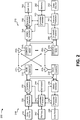
- FIG. 2 is an illustration of example components of a base station/eNodeB 210 and a UE 215 configured in accordance with an aspect of the present disclosure.
- base station/eNodeB 210 and UE 215, shown in FIG. 2 may correspond to base station/eNodeB 105 and UE 115, respectively, shown in FIG. 1 .
- Base station 210 may be equipped with antennas 234 1-t
- UE 215 may be equipped with antennas 252 1-r wherein t and r are integers greater than or equal to one.
- a base station transmit processor 220 may receive data from a base station data source 212 and control information from a base station controller/processor 240.
- the control information may be carried on the Physical Broadcast Channel (PBCH), the Physical Control Format Indicator Channel (PCFICH), the Physical Hybrid-ARQ Indicator Channel (PHICH), the Physical Downlink Control Channel (PDCCH), or the like.
- the data may be carried on the Physical Downlink Shared Channel (PDSCH), for example.
- Base station transmit processor 220 may process (e.g., encode and symbol map) the data and control information to obtain data symbols and control symbols, respectively.
- Base station transmit processor 220 may also generate reference symbols, e.g., for the PSS, SSS, and cell-specific reference signal (RS).
- RS cell-specific reference signal
- a base station transmit (TX) multiple-input multiple-output (MIMO) processor 230 may perform spatial processing (e.g., precoding) on the data symbols, the control symbols, and/or the reference symbols, if applicable, and may provide output symbol streams to base station modulators/demodulators (MODs/DEMODs) 232 1-t .
- Each base station modulator/demodulator 232 may process a respective output symbol stream (e.g., for orthogonal frequency-division multiplexing (OFDM), or the like) to obtain an output sample stream.
- Each base station modulator/demodulator 232 may further process (e.g., convert to analog, amplify, filter, and upconvert) the output sample stream to obtain a downlink signal.
- Downlink signals from modulators/demodulators 232 1-t may be transmitted via antennas 234 1-t , respectively.
- UE antennas 252 1-r may receive the downlink signals from base station 210 and may provide received signals to UE modulators/demodulators (MODs/DEMODs) 254 1-r , respectively.
- Each UE modulator/demodulator 254 may condition (e.g., filter, amplify, downconvert, and digitize) a respective received signal to obtain input samples.
- Each UE modulator/demodulator 254 may further process the input samples (e.g., for OFDM, etc.) to obtain received symbols.
- a UE MIMO detector 256 may obtain received symbols from all UE modulators/demodulators 254 1-r , and perform MIMO detection on the received symbols, if applicable, and provide detected symbols.
- a UE reception processor 258 may process (e.g., demodulate, deinterleave, and decode) the detected symbols, provide decoded data for UE 215 to a UE data sink 260, and provide decoded control information to a UE controller/processor 280.
- a UE transmit processor 264 may receive and process data (e.g., for the Physical Uplink Shared Channel (PUSCH)) from a UE data source 262 and control information (e.g., for the Physical Uplink Control Channel (PUCCH)) from UE controller/processor 280.
- UE transmit processor 264 may also generate reference symbols for a reference signal.
- the symbols from UE transmit processor 264 may be precoded by a UE TX MIMO processor 266, if applicable, may be further processed by UE modulator/demodulators 254 1-r (e.g., for SC-FDM, etc.), and may be transmitted to base station 210.
- the uplink signals from UE 215 may be received by base station antennas 234, processed by base station modulators/demodulators 232, detected by a base station MIMO detector 236, if applicable, and further processed by a base station reception processor 238 to obtain decoded data and control information sent by UE 215.
- Base station reception processor 238 may provide the decoded data to a base station data sink 246 and the decoded control information to base station controller/processor 240.
- Base station controller/processor 240 and UE controller/processor 280 may direct the operation at base station 210 and UE 215, respectively.
- Base station controller/processor 240 and/or other processors and modules at base station 210 may perform or direct, for example, execution of various processes for the techniques described herein.
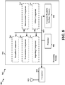
- UE controller/processor 280 and/or other processors and modules at UE 215 may also perform or direct, for example, execution of one or more blocks illustrated in FIG. 3B , and/or other processes for the techniques described herein.
- a base station memory 242 and a UE memory 282 may store data and program codes for base station 210 and UE 215, respectively.
- a scheduler 244 may schedule UEs 215 for data transmission on the downlink and/or uplink.
- base station 210 may include means for generating a compact Downlink Control Information (DCI) for at least one of uplink (UL) or downlink (DL) transmissions, wherein the compact DCI includes a reduced number of bits when compared to certain standard DCI formats; and means for transmitting the DCI.
- the aforementioned means may be base station controller/processor 240, base station memory 242, base station transmit processor 220, base station modulators/demodulators 232, and/or base station antennas 234 configured to perform the functions recited by the aforementioned means.
- the aforementioned means may be a module or any apparatus configured to perform the functions recited by the aforementioned means.
- UE 215 may include means for receiving compact Downlink Control Information (DCI) for at least one of uplink (UL) or downlink (DL) transmissions, wherein the DCI includes a reduced number of bits of a standard DCI format; and means for processing the DCI.
- the aforementioned means may be UE controller/processor 280, UE memory 282, UE reception processor 258, UE MIMO detector 256, UE modulators/demodulators 254, and/or UE antennas 252 configured to perform the functions recited by the aforementioned means.
- the aforementioned means may be a module or any apparatus configured to perform the functions recited by the aforementioned means. FIGs.
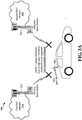
- FIG. 3A and 3B are a diagrams illustrating an example of a UE having a high gain antenna (hereinafter, high gain UE) 306 operating in a communications network 300, in accordance with various aspects of the present disclosure.
- a high gain UE 306 is moving from a coverage area associated with a first RAT 310 (e.g., an LTE RAT) to a coverage area associated with a second RAT 320 (e.g., a 3G RAT).
- the high gain UE 306 is a vehicle configured with an antenna for wireless communications in the network 300.
- the UE 306 in FIGs. 3A and 3B corresponds to UE 115 in FIG.
- a serving base station 302 associated with first RAT 310 is in a communication session with the high gain UE 306.
- the serving base station 302 in FIGs. 3A and 3B corresponds to a serving base station 105 in FIG. 1 .
- the high gain UE 306 determines that a power parameter measured based on a received signal power of a communication with serving base station 302 is greater than a power threshold.
- the power parameter may be an RSRP value.
- the high gain UE 306 may periodically report the power parameter to serving base station 302.
- serving base station 302 may not initiate a handover to neighbor base station 304 associated with second RAT 320 when the power parameter is greater than a handover threshold used to trigger the handover.
- the neighbor base station 304 in FIGs. 3A and 3B corresponds to a neighbor base station 105 in FIG. 1 .
- the high gain UE 306 may report the power parameter to serving base station 302 when the power parameter is less than a power threshold. In such a case, the high gain UE 306 may fail to report the power parameter early enough for serving base station 302 to be able to initiate the handover to neighbor base station 304. In the example cases described with respect to FIG. 3A , the communication session may be dropped.
- the high gain UE 306 measures a quality parameter based on a received signal quality of a communication with serving base station 302.
- the quality parameter may be an RSRQ value.
- the quality parameter may be a more accurate measure of the quality of the communication session, as opposed to the power parameter.
- the power parameter may merely measure a received signal power associated with the communication session.
- the high gain UE 306 may modify the power parameter based on the quality parameter. For example, if the quality parameter is less than a quality threshold, then high gain UE 306 may subtract an offset value from the power parameter to determine a modified power parameter.
- High gain UE 306 may report the modified power parameter to serving base station 302, or may use the modified power parameter to trigger transmission of a measurement report to serving base station 302. In either case, serving base station 302 may initiate a handover earlier in time than had high gain UE 306 not modified the power parameter, resulting in an increased likelihood of a successful handover from serving base station 302 to neighbor base station 304. Therefore, by modifying the power parameter, the high gain UE 306 may increase the likelihood of a successful handover from first RAT 310 to second RAT 320, and may decrease the likelihood of a dropped communication session (e.g., a dropped call, a dropped data session, etc.)
- a dropped communication session e.g., a dropped call, a dropped data session, etc.
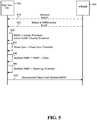
- measurement reporting may be based on events, such as Event A2 and/or Event B2.
- a first event (e.g., Event A2) may be triggered when the measured power parameter associated with the serving base station 302 minus a hysteresis value is greater than a threshold.
- a second event (e.g., Event B2) may be triggered when both the measured power parameter associated with the serving base station 302 plus a hysteresis value is less than a first threshold and a second power parameter measured for a neighbor base station (e.g., the neighbor base station 304) plus an offset minus a hysteresis value is greater than a second threshold.
- the offset, hysteresis value(s), and threshold values may be configured through signaling to the high gain UE 306, such as through RRC signaling (e.g., RRC connection/reconfiguration message(s)).
- the high gain UE 306 may be configured to send a first measurement report based on the triggering of the first event. Based on the first measurement report, the serving base station 302 may signal, to the high gain UE 306, one or more values associated with the second event, such as an offset, a first threshold, a second threshold, and the like. Thus, the high gain UE 306 may detect occurrence of the second event based on comparison of measurements (e.g., a measured power parameters from a serving base station and a neighboring base station) to values that are based on one or more parameters signaled to the high gain UE 306.
- measurements e.g., a measured power parameters from a serving base station and a neighboring base station
- measurement reporting may be triggered too late for a successful handover for the high gain UE 306 (e.g., as described with respect to FIG. 3A ).
- the high gain UE 306 may be configured to adjust the power parameter of the high gain UE 306, for example, so that measurement reporting is triggered at an earlier point and handover from the serving base station to the neighbor base station 304 may be more likely to succeed.
- the high gain UE 306 may determine that an offset is to be applied to the power parameter to form a modified power parameter.
- the offset may be a value that, when applied to the power parameter, increases the likelihood that the power parameter will satisfy a handover threshold used to trigger handover of the high gain UE 306 from the serving base station 302 to the neighbor base station 304.
- the serving base station 302 (or another network device) may initiate handover of the high gain UE 306 when the power parameter is less than a handover threshold.
- applying the offset may lower the power parameter (e.g., via subtraction, division, etc.) so that the modified power parameter is more likely to satisfy the handover threshold.
- the offset may include a preconfigured value. Additionally, or alternatively, the offset may be reconfigurable. In some aspects, the high gain UE 306 may be configured to calculate or reconfigure the offset, for example, based on network conditions, a power gain of the high gain UE 306, and the like. In one aspect, the high gain UE 306 may be configured to reconfigure the offset based on an instruction from a base station (e.g., the serving base station 302).
- a base station e.g., the serving base station 302
- the high gain UE 306 may calculate the offset based on one or more quality parameters.
- the high gain UE 306 may be configured to use a mathematical function to calculate the offset based on one or more an RSRQ value, a BLER value, an Ec/Io value, or the like.
- the high gain UE 306 may calculate the offset as a value that is inversely proportional to the quality parameter. For example, when the received signal quality is high (e.g., an RSRQ value is high, a BLER value is low, an Ec/Io value is high, etc.). Conversely, when the received signal quality is low, the high gain UE 306 may configure the offset to be a higher value. In this way, the high gain UE 306 may increase the likelihood of a successful handover when the received signal quality is low and may decrease the likelihood of an unnecessary handover when the received signal quality is high.
- the high gain UE 306 may be configured to calculate the offset based on a power gain of the high gain UE 306.
- the high gain UE 306 may be configured to use a mathematical function to calculate the offset using the power gain.
- the high gain UE 306 may be configured to calculate the offset as a value that is proportional to the power gain.
- the high gain UE 306 may increase the likelihood of handover (e.g., by decreasing the modified power parameter) when the power gain of the high gain UE 306 is high.
- the high gain UE 306 may calculate the offset based on switching between a first antenna (e.g., an internal antenna) and a second antenna (e.g., an external antenna) and computing a path loss difference.
- the high gain UE 306 may switch between a offsets of a plurality of preconfigured offsets, for example, based on RSSI (e.g., low, middle, and high regions associated with RSSI).
- the high gain UE 306 may be configured to calculate the offset based on a maximum transmission power value, an uplink BLER, or a combination of the two.
- the high gain UE 306 may employ a combination of the aforementioned techniques or additional techniques to calculate an offset and/or switch between offsets.
- the high gain UE 306 may have a power gain in a range of approximately ten (10) to fifteen (15) dB higher than a convention UE (e.g., a low gain UE).
- the offset may be calculated to be within a range of approximately 10 db to 15 dB (e.g., for an offset to be subtracted from the power parameter) or -15 dB to -10 dB (e.g., for an offset to be added to the power parameter).
- the power gain of the high gain UE 306 may be -90 dB and, therefore, the high gain UE 306 may offset the power parameter by 10 dB (e.g., by subtracting 10 dB from the power parameter) so that the modified power parameter is equal to the 100 dB that may be used by a conventional UE for measurement reporting.
- the high gain UE 306 may determine that the power gain of the high gain UE 306 is -85 dB and the high gain UE 306 offset the power parameter by 15 dB.
- the high gain UE 306 may determine a difference between approximately -100 dB and a power gain of the high gain UE 306 and may offset the power parameter by this difference.
- the base station may treat the high gain UE 306 (e.g., a car antenna) as a conventional UE (e.g., a smart phone or other low gain UE) for handover purposes.
- the high gain UE 306 e.g., a car antenna
- a conventional UE e.g., a smart phone or other low gain UE
- the high gain UE 306 may be configured to apply the offset to the power parameter based on comparison of the at least one quality parameter to the at least one quality threshold (e.g., if the quality parameter meets or exceeds the quality threshold).
- the high gain UE 306 may compare a plurality of quality parameters to a plurality of quality thresholds. For example, the high gain UE 306 may be configured to determine whether an RSRQ value is less than a first threshold and whether a BLER value is greater than a second threshold.
- the high gain UE 306 may combine a plurality of quality parameters to form a combined quality parameter (e.g., based on a mathematical function) and compare the combined quality parameter to a quality threshold.
- the high gain UE 306 may be configured to apply a weight to one or more quality parameters (e.g., when combining multiple quality parameters) and may compare one or more weighed quality parameters to one or more quality thresholds.
- the one or more quality thresholds may be one or more preconfigured values.
- the high gain UE 306 may be configured to calculate the one or more quality thresholds, for example, based on network conditions, a power gain of the high gain UE 306, or the like.
- the high gain UE 306 may be configured to modify the quality threshold based on an instruction from a base station (e.g., the serving base station 302).
- the high gain UE 306 may be configured to apply the offset to the power parameter based on a power gain of the high gain UE 306. This configuration may be in addition to or an alternative to application of the offset to the power parameter based on a quality parameter.
- the high gain UE 306 may be configured to determine the power gain of the high gain UE 306. The high gain UE 306 may compare the determined power gain to a power gain threshold. Based on comparison of the determined power gain to the power gain threshold (e.g., when the power gain meets or exceeds the power gain threshold), the high gain UE 306 may apply the offset to the power parameter.
- the high gain UE 306 may modify the power parameter to increase the likelihood of a successful handover when the power gain of the high gain UE 306 is high (e.g., where, without modification of the power parameter, handover may not be initiated until a point at which handover fails).
- the high gain UE 306 may be configured to determine the power gain of the high gain UE 306 where, for example, the high gain UE 306 communicates using a plurality of antennas or antenna arrays (e.g., an internal antenna and an external antenna), which the high gain UE 306 may switch between.
- the high gain UE 306 may provide the modified power parameter to a network device that is included in or communicatively coupled with a core network (e.g., the serving base station 302, the neighbor base station 304, an MME, or the like), and the network device may use the measurement report in association with handover of the high gain UE 306 from the serving base station 302 to the neighbor base station 304 (e.g., the network device may initiate handover of the high gain UE 306 if the modified power parameter satisfies a handover threshold or the network device may signal additional parameters for measurement reporting associated with handover to the high gain UE 306).
- a core network e.g., the serving base station 302, the neighbor base station 304, an MME, or the like
- the high gain UE 306 may transmit a measurement report that includes the modified power parameter (e.g., instead of the measured power parameter) in a measurement report.
- the high gain UE 306 may further include other values in a measurement report, such as the quality parameter, the power gain, and/or values measured for the neighbor base station 304.
- the high gain UE 306 may periodically provide a measurement report (including the modified power parameter) to a network device (e.g., the serving base station 302).
- the high gain UE 306 may provide measurement report (including the modified power parameter) to a network device (e.g., the serving base station 302) based on an event (e.g., an Event A2 and/or Event B2 as described in one or more 3GPP technical specifications).
- the event may include comparison of the modified power parameter (and/or the quality parameter) to a reporting threshold.
- the reporting threshold may include a preconfigured value. Additionally, or alternatively, the reporting threshold may be reconfigurable. In some aspects, the reporting threshold may be set to a value based on, for example, network conditions, a power gain of the high gain UE 306, or the like. In some aspects, the high gain UE 306 may receive an instruction from a base station (e.g., the serving base station 302) and may configure the reporting threshold based on the instruction from the base station.
- a base station e.g., the serving base station 302
- the high gain UE 306 may be configured to send a first measurement report based on the triggering of the first event. For example, the high gain UE 306 may be configured to transmit the modified power parameter when the modified power parameter minus a hysteresis value is greater than a reporting threshold.
- the high gain UE 306 may be configured to send the first measurement report based on Event A2; however, the modified power parameter may cause the high gain UE 306 to transmit the first measurement report at a point in time that is earlier than the point at which the high gain UE 306 would transmit the first measurement report if the high gain UE 306 were not to use the modified power parameter to detect occurrence of Event A2 (e.g., if the high gain UE 306 were to use the measured power parameter). Because the serving base station 302 may communicate a configuration for Event B2 to the high gain UE 306 based on reception of the Event A2, the serving base station 302 may signal the Event B2 configuration at a point earlier in time. The earlier reception of the Event B2 configuration at the high gain UE 306 may increase the chance that the first threshold for Event B2 will be satisfied and, therefore, increase the chance of successful handover.
- the serving base station 302 may communicate a configuration for Event B2 to the high gain UE 306 based on reception of the Event A2
- the high gain UE 306 may additionally use a second modified power parameter to determine if Event B2 is triggered and/or may include the second modified power parameter in the measurement report triggered by Event B2. For example, the high gain UE 306 may measure a second power parameter for the neighbor base station 304. The high gain UE 306 may measure a second quality parameter for the neighbor base station 304, and the high gain UE 306 may apply an offset to the second measured power parameter to form a second modified power parameter in a manner similar to that described herein with respect to the serving base station 302. However, in other aspects, the high gain UE 306 may only modify one or more power parameters for a serving base station and/or for a particular RAT (e.g., only modify LTE power parameters when handing over to 3G).
- a particular RAT e.g., only modify LTE power parameters when handing over to 3G.
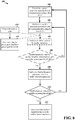
- FIG. 4 is a flow chart 400 of a method of wireless communication in accordance with various aspects of the disclosure.
- the method may be performed by a UE, such as UE 115 or UE 306.
- the UE determines a power parameter associated with a communication using a first RAT.
- the UE may measure a received signal power of one or more communications using a first RAT, and may determine a power parameter that represents the received signal power.
- the UE may receive the one or more communications from a serving base station (e.g., serving base station 302) with which the UE is communicating for a voice call (e.g., a VoLTE call), a video call, a data session, or the like.
- the serving base station may use a first RAT to communicate with the UE.
- the first RAT may include, for example, a 4G RAT, a 3G RAT, a 2G RAT, a LTE RAT, an LTE-Advanced (LTE-A) RAT, a Wi-Fi RAT, or the like.
- a 4G RAT for example, a 4G RAT, a 3G RAT, a 2G RAT, a LTE RAT, an LTE-Advanced (LTE-A) RAT, a Wi-Fi RAT, or the like.
- the UE may determine a power parameter associated with the one or more communications.
- the power parameter may represent a measurement of received signal power.
- the power parameter may represent an RSRP, an RSCP, an RSSI, a ratio of a received energy per chip (e.g., code bit) to an interference level (Ec/Io), or the like.
- the power parameter may be represented using a value, such as a decibel value (e.g., a received signal power value, an RSRP value, an RSCP value, an RSSI value, an Ec/Io value, etc.).
- the UE may determine the power parameter as part of a reporting process used for handover of UE from the serving base station to a neighbor base station (e.g., neighbor base station 304).
- the serving base station may be associated with a first RAT and neighbor base station may be associated with a second RAT.
- the second RAT may include, for example, a 4G RAT, a 3G RAT (e.g., Universal Mobile Telecommunications System (UMTS), High Speed Packet Access (HSPA), Code Division Multiple Access (CDMA), etc.), a 2G RAT, an LTE RAT, an LTE-A RAT, a Wi-Fi RAT, or the like.
- the first RAT may be different from the second RAT.
- the handover may include an inter-RAT handover.
- the UE determines a quality parameter associated with the communication using the first RAT. For example, the UE may measure a received signal quality of one or more communications using the first RAT, and may determine a quality parameter that represents the received signal quality. In some aspects, the UE may receive the one or more communications from the serving base station as previously described.
- the UE may determine a quality parameter associated with the one or more communications.
- the quality parameter may represent a measurement of received signal quality.
- the quality parameter may represent an RSRQ, a BLER, an SINR, or the like.
- the quality parameter may be represented using a value, such as a decibel value (e.g., a received signal quality value, an RSRQ value, a BLER value, an SINR value, etc.).
- the UE may determine multiple quality parameters (e.g., an RSRQ value and a BLER value, an RSRQ value and an SINR value, a BLER value and an SINR value, etc.).
- the UE may use the quality parameter to modify the power parameter, and may report the modified power parameter to the serving base station for a handover. Additionally, or alternatively, the UE may use the quality parameter to determine whether to provide a measurement report to the serving base station for the handover.
- the UE is a high gain UE (e.g., with a power gain that satisfies a power gain threshold)
- using the received signal quality in this way may increase the likelihood of a successful handover.
- the UE determines that the quality parameter satisfies a quality threshold. For example, the UE may determine that the quality parameter (e.g., an RSRQ value, a BLER value, an SINR value, etc.) satisfies a quality threshold. In some aspects, the UE may use the quality threshold to determine whether to modify the power parameter. In some aspects, the UE may use the quality threshold to determine whether to provide a measurement report to the serving base station.
- the quality parameter e.g., an RSRQ value, a BLER value, an SINR value, etc.
- the quality threshold may include a preconfigured value. Additionally, or alternatively, the quality threshold may be reconfigurable. In some aspects, the quality threshold may be set to a value based on, for example, network conditions, a power gain of the UE, or the like.
- the UE may receive an instruction from a base station (e.g., the serving base station) to modify the quality threshold. In such aspect, the UE may modify the quality threshold based on the instruction.
- the UE may compare the quality parameter and the quality threshold to determine whether the quality parameter satisfies the quality threshold. In an aspect, the UE may determine that the quality parameter satisfies the quality threshold when the quality parameter is less than or equal to the quality threshold. For example, the UE may determine whether an RSRQ value is less than or equal to the quality threshold.
- the UE may compare multiple quality parameters to multiple quality thresholds. In this case, the UE may determine whether a first quality parameter satisfies a first quality threshold, whether a second quality parameter satisfies a second quality threshold, and so on. For example, the UE may determine whether the RSRQ value is less than a first threshold, and may determine whether the BLER value is greater than a second threshold.
- the UE may combine multiple quality parameters (e.g., using a mathematical function) to form a combined parameter, and may compare the combined parameter to a quality threshold. Additionally, or alternatively, the UE may apply a weight to one or more quality parameters (e.g., when combining multiple quality parameters), and may compare a resulting parameter to a quality threshold.
- multiple quality parameters e.g., using a mathematical function
- the UE may apply a weight to one or more quality parameters (e.g., when combining multiple quality parameters), and may compare a resulting parameter to a quality threshold.
- the UE determines that a power gain satisfies a power gain threshold. For example, the UE may determine a power gain of the UE (e.g., an antenna gain of the UE or a power gain of a receiver of the UE that receives communications). The UE may determine whether the power gain satisfies a power gain threshold. In an aspect, the UE may determine that a power gain satisfies a power gain threshold when the power gain is greater than the power gain threshold. If the power gain satisfies the power gain threshold, the UE may modify a power parameter reported to the serving base station for a handover. Without such modification, the serving base station may fail to handover the UE to the neighbor base station.
- a power gain of the UE e.g., an antenna gain of the UE or a power gain of a receiver of the UE that receives communications.
- the UE may determine whether the power gain satisfies a power gain threshold.
- the UE may determine that a
- the power gain threshold may include a preconfigured value. Additionally, or alternatively, the power gain threshold may be reconfigurable. In some aspects, the power gain threshold may be set to a value based on, for example, network conditions, a power gain of the UE, or the like. In some aspects, the UE may receive an instruction from a base station (e.g., from the serving base station) to modify the power gain threshold. In such aspects, the UE may modify the power gain threshold based on the instruction.
- a base station e.g., from the serving base station
- the UE may have a power gain of approximately -100 dB.
- the UE is a high gain UE, such as a vehicle with an antenna (e.g., a car with a roof-top antenna), or the like, may have a power gain in a range of approximately -90 dB to -85 dB.
- a high gain UE may have a power gain in a range of approximately 10 dB to approximately 15 dB higher than a low gain UE.
- the UE may set a power gain threshold to -100 dB, -95 dB, -90 dB, or the like.
- the UE applies an offset to the power parameter to form a modified power parameter.
- the UE may apply an offset (e.g., an offset value) to the power parameter (e.g., an RSRP value, an RSCP value, an Ec/Io value, an RSSI value, etc.) to determine a modified power parameter.
- an offset e.g., an offset value
- the power parameter e.g., an RSRP value, an RSCP value, an Ec/Io value, an RSSI value, etc.
- the offset may include a value that, when applied to the power parameter, increases the likelihood that the power parameter will satisfy a handover threshold used to trigger handover of the UE from the serving base station to the neighbor base station.
- a handover threshold used to trigger handover of the UE from the serving base station to the neighbor base station.
- the serving base station or another network device
- applying the offset may lower the power parameter (e.g., via subtraction, division, etc.) so that the modified power parameter is more likely to satisfy the handover threshold.
- the UE may apply the offset based on determining that the quality parameter satisfies the quality threshold. In this way, the UE may modify the power parameter to increase the likelihood of a handover when the quality of a communication session with the serving base station deteriorates. Additionally, or alternatively, the UE may apply the offset based on determining that the power gain satisfies the power gain threshold. In this case, the UE may modify the power parameter to increase the likelihood of a handover when the UE is a high gain UE (e.g., which, without modifying the power parameter, may not be handed over).
- the offset may include a preconfigured value. Additionally, or alternatively, the offset may be reconfigurable. In some aspects, the offset may be set to a value based on, for example, network conditions, a power gain of the UE, or the like. In some aspects, the UE may receive an instruction from a base station (e.g., from the serving base station) to modify the offset. In such aspects, the UE may modify the offset based on the instruction.
- a base station e.g., from the serving base station
- the UE may calculate the offset based on one or more quality parameters. For example, the UE may use a mathematical function to calculate the offset using one or more of the RSRQ value, the BLER value, the Ec/Io value, the RSSI value, or the like. In some aspects, the UE may calculate the offset as a value that is inversely proportional to the quality parameter. As an example, when the received signal quality is high (e.g., when an RSRQ value is high, when a BLER value is low, when an Ec/Io value is high, when an RSSI value is high, etc.), the UE may set the offset to a lower value. Conversely, when the received signal quality is low, the UE may set the offset to a higher value. In this way, the UE may increase the likelihood of a handover (e.g., by decreasing the modified power parameter) when the received signal quality is low, and may decrease the likelihood of a handover when the received signal quality is high.
- the UE may increase the likelihood of a handover (
- the UE may calculate the offset based on a power gain of the UE.
- the UE may use a mathematical function to calculate the offset using the power gain.
- the UE may calculate the offset as a value that is proportional to the power gain.
- the power gain is high (e.g., when the UE is a high gain UE, when the power gain is greater than a threshold, etc.)
- the UE may set the offset to a higher value.
- the power gain is low (e.g., when the UE is not a high gain UE, when the power gain is less than a threshold, etc.)
- the UE may set the offset to a lower value. In this way, the UE may increase the likelihood of a handover (e.g., by decreasing the modified power parameter) when the power gain of the UE is high.
- a high gain UE may have a power gain in a range of approximately 10 dB to approximately 15 dB higher than a low gain UE.
- the offset may be set within a range of approximately 10 dB to approximately 15 dB (e.g., when the offset is subtracted from the power parameter), or may be set within a range of approximately -15 dB to approximately -10 dB (e.g., when the offset is added to the power parameter).
- the UE may offset the power parameter by 10 dB (e.g., by subtracting 10 dB from the power parameter).
- the UE may offset the power parameter by 15 dB.
- the UE may determine a difference between approximately -100 dB and a power gain of the UE, and may offset the power parameter by this difference.
- the base station may treat the high gain UE (e.g., a car antenna) like a low gain UE (e.g., a smart phone) for handover purposes.
- the high gain UE e.g., a car antenna
- a low gain UE e.g., a smart phone
- the UE determines that the modified power parameter satisfies a reporting threshold. For example, the UE may determine whether the modified power parameter (e.g., the power parameter modified by the offset) satisfies a reporting threshold. If the modified power parameter satisfies the reporting threshold (e.g., if the modified power parameter is less than the reporting threshold), then the UE may provide a measurement report to the serving base station.
- the modified power parameter e.g., the power parameter modified by the offset
- the reporting threshold may include a preconfigured value. Additionally, or alternatively, the reporting threshold may be reconfigurable. In some aspects, the reporting threshold may be set to a value based on, for example, network conditions, a power gain of the UE, or the like. In some aspects, the UE may receive an instruction from a base station (e.g., from the serving base station) to modify the reporting threshold. In such aspects, the UE may modify the reporting threshold based on the instruction.
- a base station e.g., from the serving base station
- the UE provides a measurement report, including the modified power parameter, for a handover from the first RAT to a second RAT.
- the UE may provide the measurement report to a core network (e.g., via the serving base station, a neighbor base station, etc.).
- the UE may include the modified power parameter in the measurement report.
- the UE may include one or more other parameters in the measurement report, such as the quality parameter, the power gain, or the like.
- the UE may include one or more parameters (e.g., a power parameter, a quality parameter, etc.), associated with a communication from a neighbor base station, in the measurement report.
- the UE may provide the measurement report based on determining that the modified power parameter satisfies the reporting threshold, as described above. Additionally, or alternatively, the UE may periodically provide the measurement report (e.g., including the modified power parameter).
- a network device e.g., serving base station, neighbor base station, a mobility management entity (MME), another network device, etc.
- MME mobility management entity
- the network device may use the measurement report to determine whether to handover the UE from the serving base station to a neighbor base station. For example, the network device may determine to handover the UE when the reported power parameter (in this case, the modified power parameter) satisfies a handover threshold (e.g., is less than a handover threshold).
- a handover threshold e.g., is less than a handover threshold
- the serving base station and neighbor base station may be associated with different RATs.
- the UE may modify a power parameter to increase the likelihood of a successful inter-RAT handover and to decrease the likelihood of a dropped communication session.
- flow chart 400 may include additional blocks, fewer blocks, different blocks, or differently arranged blocks than those depicted in FIG. 4 . Additionally, or alternatively, two or more of the blocks in FIG. 4 may be performed in parallel.
- FIG. 5 is an illustration of an example call flow diagram 500 relating to the method of wireless communication shown in FIG. 3B .
- FIG. 5 includes a high gain UE 502 and an eNodeB 504.
- the high gain UE 502 corresponds to the high gain UE 306 in FIG. 3B
- the eNodeB 504 corresponds to the serving base station 302 in FIG. 3B .
- the UE 502 may measure an RSRP (e.g., to determine an RSRP parameter) of a communication with eNodeB 504. As shown by reference number 520, the UE 502 may also measure an RSRQ and/or a BLER of a communication with eNodeB 504. As shown by reference number 530, UE 502 may determine that the measured RSRQ (e.g., an RSRQ parameter) is less than a quality threshold, and/or may determine that the measured BLER is greater than a quality threshold.
- RSRP e.g., to determine an RSRP parameter
- the UE 502 may determine that a quality parameter satisfies a quality threshold (e.g., that a first quality parameter is less than a first quality threshold, that a second quality parameter is greater than a second quality threshold, etc.).
- a quality threshold e.g., that a first quality parameter is less than a first quality threshold, that a second quality parameter is greater than a second quality threshold, etc.
- the UE 502 determines that a power gain of the UE 502 is greater than a power gain threshold. Based on determining that the quality parameter satisfies the quality threshold, and based on determining that the power gain satisfies the power gain threshold, the UE 502 may modify an RSRP parameter, determined based on the measured RSRP, using an offset. For example, the UE 502 may subtract an offset value from the RSRP parameter to determine a modified RSRP parameter (shown as "Modified RSRP”), as shown by reference number 550.
- Modified RSRP modified RSRP parameter
- the UE 502 may determine that the modified RSRP parameter is less than a reporting threshold. Based on determining that the modified RSRP parameter is less than the reporting threshold, the UE 502 may provide the measurement report, including the modified RSRP parameter, to the eNodeB 504, as illustrated by reference number 570. Additionally, or alternatively, the UE 502 may periodically provide the measurement report, including the modified RSRP parameter, to the eNodeB 504 regardless of whether the modified RSRP parameter is less than the reporting threshold. In this way, the eNodeB 504 may use the modified RSRP parameter to determine whether to handover the high gain UE 502 to a neighbor base station, thereby increasing the likelihood the high gain UE 502 is successfully handed over.
- call flow diagram 500 may include additional operations, fewer operations, different operations, or differently arranged operations than those depicted in FIG. 5 . Additionally, or alternatively, two or more of the operations of call flow diagram 500 may be performed in parallel.
- a flowchart illustrates a method 600 for modifying a power parameter based on a quality parameter in association with measurement reporting, in accordance with various aspects of the present disclosure.
- the method 600 may be performed by a UE, and more specifically by a high gain UE (e.g., the high gain UE 306 of FIG. 3B , the apparatus 800/702').
- a high gain UE e.g., the high gain UE 306 of FIG. 3B , the apparatus 800/702'.
- various operations are illustrated as optional (e.g., denoted by dashed lines). However, the present disclosure contemplates operations in which one or more operations of the method 600 are optional, omitted, and/or alternatively performed according to various aspects. Further, one or more operations of the method 600 may be transposed and/or contemporaneously performed.
- the method 600 may begin with an operation 602 at which a UE may determine a power parameter associated with communication using a first RAT.
- the power parameter may include a RSRP value, a RSCP value, a RSSI, or another value indicative of a power level of received signals from a network device.
- the power parameter may be a dB value.
- the high gain UE 306 may measure a power parameter associated with the serving base station 302, which communicates with the high gain UE 306 using the first RAT 310.
- the UE may determine a quality parameter associated with the communication using the first RAT.
- the quality parameter may include at least one of a RSRQ value, a BLER value, a SINR value, a Ec/Io value, or another value that is indicative of a quality of signals received from a network device.
- the high gain UE 306 may measure a quality parameter associated with the serving base station 302, which communicates with the high gain UE 306 using the first RAT 310.
- the method 600 may include operations 630 and 632.
- the UE may determine a power gain.
- the UE may determine a power gain of an antenna that the UE is currently using for communication according to the first RAT.
- the high gain UE 306 may determine the power gain of an antenna of the high gain UE 306 used to communicate with the serving base station 302.
- the UE may determine whether the power gain satisfies a power gain threshold. For example, the UE may determine whether the power gain meets or exceeds a power gain threshold. If the power gain does not satisfy the power gain threshold, then the UE may determine that a power parameter for the UE may not need to be modified, and the UE may return to one of the aforementioned operations, such as operation 602 or operation 604.
- the high gain UE 306 may determine whether power gain of an antenna of the high gain UE 306 satisfies a power gain threshold.
- the UE may calculate an offset, as illustrated at operation 605.
- the UE may calculate the offset based on the quality parameter.
- the UE may switch between a first antenna (e.g., an internal antenna) and a second antenna (e.g., an external antenna) and may compute the path loss as an indication of the gain of the second antenna.
- the UE may switch between offsets of a plurality of preconfigured offsets based on an RSSI value.
- the UE may compute the offset based on a maximum transmission power value, an uplink BLER value, or a combination of the two values.
- the high gain UE 306 may compute an offset for the power parameter measured with respect to the serving base station 302.
- the UE may determine whether the quality parameter satisfies a quality threshold, as illustrated at operation 606. For example, the UE may determine if the quality parameter meets or exceeds a quality threshold. Alternatively, or additionally, the UE may determine whether the power gain satisfies a power gain threshold (as illustrated at operations 630-632). In the context of FIG. 3B , the high gain UE 306 may determine whether a quality parameter measured for the serving base station 302 satisfies a quality threshold. Alternatively, or additionally, the high gain UE 306 may determine whether the power gain of the high gain UE 306 satisfies a power gain threshold.
- the method 600 may return to operation 604, where the UE may again determine a quality parameter (and/or determine a power gain, such as where the UE switches from an internal antenna to an external antenna).
- the method 600 may advance to operation 608.
- the UE may apply an offset to the power parameter to form a modified power parameter.
- the UE may use the modified power parameter where the measured power parameter would normally be used, such as to determine measurement reporting and/or in a field of a measurement report dedicated to the power parameter (e.g., an RSRP field of a measurement report).
- the high gain UE 306 may apply an offset to the power parameter measured for the serving base station 302.
- the UE may determine whether the modified power parameter satisfies a reporting threshold. For example, the UE may determine whether the modified power parameter meets or exceeds a reporting threshold at which measurement reporting is triggered. In the context of FIG. 3B , the UE may determine whether the modified power parameter satisfies a reporting threshold, which may trigger transmission of a measurement report to the serving base station 302 and/or the neighbor base station 304.
- the reporting threshold may be associated with an Event A2, which may trigger a measurement report when a power parameter measured for a serving base station becomes worse than a threshold.
- the reporting threshold may be associated with an Event B2, which may trigger a measurement report when a power parameter measured for a serving base station becomes worse than a first threshold while a power parameter measured for a neighbor inter-RAT base station becomes better than a second threshold.
- the method 600 may return to operation 602, where the UE may again determine a power parameter. However, if the UE determines that the modified power parameter does satisfy the reporting threshold, the UE may proceed to operation 612.
- the UE may transmit a measurement report that includes the modified power parameter.
- the high gain UE 306 may transmit a measurement report that includes the modified power parameter to the serving base station 302 and/or the neighbor base station 304.
- the measurement report may be associated with an Event A2, which may be associated with degradation of communication with the serving base station, such as when a power parameter measured for a serving base station falls below a threshold.
- the measurement report may be associated with an Event B2, which may be associated with both degradation of communication with a serving base station and improved communication with a neighbor inter-RAT base station, such as when a power parameter measured for a serving base station becomes worse than a first threshold while a power parameter measured for a neighbor inter-RAT base station becomes better than a second threshold.
- the UE may use the modified power parameter (measured with respect to a serving base station) both to determine when a measurement report is triggered and to include in the triggered measurement report.
- FIG. 7 is a conceptual data flow diagram 700 illustrating the data flow between different means/components in an exemplary apparatus 702.
- the apparatus may be a UE, and more specifically a high gain UE (e.g., the high gain UE 306 of FIG. 3B ).
- the apparatus 702 depicts exemplary connections and/or data between different modules/means/components. It is to be understood that such connections and/or data flow are to be regarded in as illustrative and, therefore, different and/or additional connections and/or data flow may be present in different aspects.
- the apparatus 702 may include a reception component 704.
- the reception component 704 may receive signals from a base station and/or a wireless device (e.g., the base station 750).
- the reception component 704 may receive information associated with measurement reporting, such as one or more parameters for reporting, for example, from the base station 650.
- the parameters for reporting may include one or more thresholds indicating information (e.g., a dB value) for one or more of power parameters and/or quality parameters at which the apparatus 702 is to transmit a measurement report.
- the reporting parameters may be associated with a first event (e.g., Event A2) that may be triggered when the apparatus 702 measures a power parameter based on signals received from the base station 750 (e.g., a serving base station) or another base station (e.g., a neighbor base station).
- the reporting parameters may be associated with a second event (e.g., Event B2) that may be triggered when the apparatus 702 measures a power parameter based on signals received from the base station 750 (e.g., a serving base station) and another base station (e.g., a neighbor base station).
- the reporting parameters may further include an offset associated with a base station (e.g., a neighbor base station for Event B2), one or more hysteresis value(s), and the like.
- the reception component 704 may further receive signals from which the apparatus 702 may measure parameters associated with signal power and/or quality.
- the reception component 704 may receive reference signals from the base station 750 (e.g., a serving base station) and/or another base station (e.g., a neighbor base station).
- the apparatus 702 may include a measurement component 712.
- the measurement component may be configured to receive signals from the reception component 704, such as reference signals from the base station 750 (e.g., a serving base station) and/or another base station (e.g., a neighbor base station).
- the base station 750 e.g., a serving base station
- another base station e.g., a neighbor base station
- the measurement component 712 may be configured to measure one or more power parameter(s) based on signals received from reception component 704.
- the measurement component 712 may measure a RSRP value, a RSCP value, a RSSI, or another value indicative of a power level associated with signals received from the base station 750 (e.g., a serving base station).
- the measurement component 712 may measure a RSRP value, a RSCP value, a RSSI, or another value indicative of a power level associated with signals received from another base station (e.g., a neighbor base station).
- the power parameter(s) may be a dB value.
- the measurement component 712 may additionally measure one or more quality parameter(s). For example, the measurement component 712 may measure a RSRQ value, a BLER value, a s SINR value, a Ec/Io value, or another value that is indicative of a quality of signals received from the base station 750 (e.g., a serving base station). In some aspects, the measurement component 712 may measure a RSRQ value, a BLER value, a s SINR value, a Ec/Io value, or another value that is indicative of a quality of signals received from another base station (e.g., a neighbor base station). The quality parameter(s) may be a dB value.
- the apparatus 702 may include an offset component 714.
- the offset component 714 may be configured to receive one or more power parameter(s) and/or quality parameter(s) from the measurement component 712.
- the offset component 714 may be configured to form a modified power parameter based on application of an offset to a measured power parameter for the base station 750 (e.g., a serving base station).
- the offset component 714 may be configured to apply an offset to a measured power parameter based on a measured quality parameter.
- the offset component 714 may determine whether a measured quality parameter satisfies a quality threshold. For example, the offset component 714 may determine if a measured quality parameter meets or exceeds a quality threshold. If the offset component 714 determines that the quality parameter satisfies the quality threshold, then the offset component 714 may apply an offset to a measured power parameter to form a modified power parameter.
- the offset may be a predetermined value, such as a value stored in a data structure that may be accessed by the offset component 714.
- the offset component 714 may calculate an offset. For example, the offset component 714 may calculate the offset based on the quality parameter.
- the offset component 714 may switch between a first antenna (e.g., an internal antenna) and a second antenna (e.g., an external antenna) and may compute the path loss as an indication of the gain of the second antenna, which may be used as the offset.
- the offset component 714 may switch between offsets of a plurality of preconfigured offsets based on an RSSI value.
- the offset component 714 may compute the offset based on a maximum transmission power value, an uplink BLER value, or a combination of the two values.
- the apparatus 702 may further include a reporting component 716.
- the reporting component 716 may be configured to generate one or more measurement reports.
- the reporting component 716 may be configured to generate measurement reports associated with a serving cell (e.g., a cell provided by the base station 750), a neighbor cell (e.g., a cell provided by a neighbor base station targeted for handover), and/or a combination thereof.
- the reporting component 716 may be configured to generate measurement reports in association with events for various wireless standards, such as Event A2 and Event B2 (e.g., LTE Event A2, LTE Event B2, and the like).
- the reporting component 716 may be configured to receive power parameters and/or quality parameters from the measurement component 712.
- Power parameters and quality parameters received from the measurement component 712 may be measured values (e.g., raw values, values that have not had an offset applied thereto).
- the power parameters received from the measurement component 712 may be power parameters associated with a neighbor base station, such as a neighbor base station targeted for inter-RAT handover.
- the quality parameters received from the measurement component 712 may be quality parameters for the base station 750 (e.g., a serving base station) and/or a neighbor base station (e.g., a neighbor base station targeted for inter-RAT handover).
- the reporting component 716 may be configured to receive modified power parameters from the offset component 714.
- the reporting component 716 may be configured to use modified power parameters where the measured power parameters would normally be used.
- the reporting component 716 may include a modified power parameter for the base station 750 (e.g., a serving base station) in a measurement report.
- the reporting component 716 may be configured to use a modified power parameter for the base station 750 (e.g., a serving base station) to determine when a measurement report is to be transmitted.
- the reporting component may compare a modified power parameter for the base station 750 (e.g., a serving base station) to a threshold associated with a reporting event (e.g., Event A2 and/or Event B2, as described herein).
- a reporting event e.g., Event A2 and/or Event B2, as described herein.
- the reporting component 716 may provide a measurement report to the transmission component 706.
- the transmission component 706 may be configured to transmit signals to a base station, such as a base station 750 (e.g., a serving base station) or a neighbor base station.
- a base station 750 e.g., a serving base station
- the transmission component 706 may be configured to transmit measurement reports that include modified power parameters (and, optionally, quality parameters and/or other measured power parameters) to the base station 750.
- the apparatus may include additional components that perform each of the blocks of the algorithm in the aforementioned flowchart of FIG. 4 , call flow of FIG. 5 , and/or flowchart of FIG. 6 .
- each block/operation in the aforementioned call flow/flowcharts of FIGs. 4 , 5 and 6 may be performed by a component and the apparatus may include one or more of those components.
- the components may be one or more hardware components specifically configured to carry out the stated processes/algorithm, implemented by a processor configured to perform the stated processes/algorithm, stored within a computer-readable medium for implementation by a processor, or some combination thereof.
- FIG. 8 is a diagram 800 illustrating an example of a hardware implementation for an apparatus 702' employing a processing system 814.
- the processing system 814 may be implemented with a bus architecture, represented generally by the bus 824.
- the bus 824 may include any number of interconnecting buses and bridges depending on the specific application of the processing system 814 and the overall design constraints.
- the bus 824 links together various circuits including one or more processors and/or hardware components, represented by the processor 804, the components 704, 706, 712, 714, 716, and the computer-readable medium / memory 806.
- the bus 824 may also link various other circuits such as timing sources, peripherals, voltage regulators, and power management circuits, which are well known in the art, and therefore, will not be described any further.
- the processing system 814 may be coupled to a transceiver 810.
- the transceiver 810 is coupled to one or more antennas 820.
- the transceiver 810 provides a means for communicating with various other apparatus over a transmission medium.
- the transceiver 810 receives a signal from the one or more antennas 820, extracts information from the received signal, and provides the extracted information to the processing system 814, specifically the reception component 704.
- the transceiver 810 receives information from the processing system 814, specifically the transmission component 706, and based on the received information, generates a signal to be applied to the one or more antennas 820.
- the processing system 814 includes a processor 804 coupled to a computer-readable medium / memory 806.
- the processor 804 is responsible for general processing, including the execution of software stored on the computer-readable medium / memory 806.
- the software when executed by the processor 804, causes the processing system 814 to perform the various functions described supra for any particular apparatus.
- the computer-readable medium / memory 806 may also be used for storing data that is manipulated by the processor 804 when executing software.
- the processing system 814 further includes at least one of the components 704, 706, 712, 714, 716.
- the components may be software components running in the processor 804, resident/stored in the computer readable medium / memory 806, one or more hardware components coupled to the processor 804, or some combination thereof.
- the processing system 814 may be a component of the UE 215 and may include the memory 282 and/or at least one of the transmit processor 266, the reception processor 258, and the controller/processor 280.
- the apparatus 800/702' for wireless communication includes means for determining, by the apparatus, a power parameter associated with communication using a first RAT.
- the apparatus 800/702' further includes means for determining, by the apparatus, a quality parameter associated with the communication using the first RAT.
- the apparatus 800/702' further includes means for applying, by the apparatus and based on the quality parameter, an offset to the power parameter to form a modified power parameter.
- the apparatus 800/702' further includes means for transmitting, by the apparatus, a measurement report including the modified power parameter.
- the power parameter may include a RSRP.
- the quality parameter may include a RSRQ or a BLER.
- the apparatus 800/702' further may further include means for determining (e.g., calculating) the offset based on the quality parameter.
- the means for applying the offset is further configured to apply the offset based on determining that a power gain satisfies a power gain threshold.
- the apparatus 800/702' may further include means for determining the power gain.
- the apparatus 800/702' may further include means for determining that the power gain satisfies the power gain threshold.
- the means for applying, based on the quality parameter, the offset to the power parameter to form a modified power parameter is configured to determine that the quality parameter satisfies a quality threshold and apply the offset to the power parameter when the quality parameter satisfies the quality threshold.
- the means for applying the offset to the power parameter is further configured to apply the offset based on determining that a second quality parameter satisfies a second quality threshold.
- the apparatus 800/702' may further include means for determining that the second quality parameter satisfies the second quality threshold.
- the means for transmitting the measurement report is configured to transmit the measurement report based on determining that the modified power parameter satisfies a reporting threshold.
- the apparatus 800/702' may further include means for determining that the modified power parameter satisfies the reporting threshold.
- the measurement report is transmitted to a serving base station in association with handover to a neighbor base station.
- the apparatus 800/702' may further include means for receiving the communication from the serving base station, the serving base station associated with a first RAT and the neighbor base station associated with a second RAT.
- the first RAT is different from the second RAT.
- the aforementioned means may be one or more of the aforementioned components of the apparatus 702 and/or the processing system 814 of the apparatus 702' configured to perform the functions recited by the aforementioned means.
- the processing system 814 may include the transmit processor 264, the reception processor 258, and the controller/processor 280.
- the aforementioned means may be the transmit processor 264, the reception processor 258, and the controller/processor 280 configured to perform the functions recited by the aforementioned means.
- combinations such as “at least one of A, B, or C,” “at least one of A, B, and C,” and “A, B, C, or any combination thereof' may be A only, B only, C only, A and B, A and C, B and C, or A and B and C, where any such combinations may contain one or more member or members of A, B, or C.
- nothing disclosed herein is intended to be dedicated to the public regardless of whether such disclosure is explicitly recited in the claims. No claim element is to be construed as a means plus function unless the element is expressly recited using the phrase "means for.”
- a method for wireless communication comprising determining, by a user equipment (UE), a power parameter associated with communication using a first radio access technology (RAT), determining, by the UE, a quality parameter associated with the communication using the first RAT, applying, by the UE and based on the quality parameter, an offset to the power parameter to form a modified power parameter and transmitting, by the UE, a measurement report including the modified power parameter.
- the power parameter may comprise a reference signal received power (RSRP).
- the quality parameter may comprise a reference signal received quality (RSRQ) or a block error rate (BLER).
- the method may comprise determining the offset based on the quality parameter.
- the applying of the offset may be further based on determining that a power gain satisfies a power gain threshold, and the method may further comprise determining, by the UE, the power gain and determining, by the UE, that the power gain satisfies the power gain threshold.
- the applying, based on the quality parameter, the offset to the power parameter to form a modified power parameter may comprise determining that the quality parameter satisfies a quality threshold and applying the offset to the power parameter when the quality parameter satisfies the quality threshold.
- the applying the offset to the power parameter may be further based on determining that a second quality parameter satisfies a second quality threshold, the method may also comprise determining that the second quality parameter satisfies the second quality threshold.
- the transmitting the measurement report may be based on determining that the modified power parameter satisfies a reporting threshold, the method may also comprise determining that the modified power parameter satisfies the reporting threshold. Further, the measurement report may be transmitted to a serving base station in association with handover to a neighbor base station, the method may also comprise receiving the communication from the serving base station, the serving base station associated with a first radio access technology (RAT) and the neighbor base station associated with a second RAT. The first RAT may be different from the second RAT.
- RAT radio access technology
- an apparatus for wireless communication comprising means for determining, by the apparatus, a power parameter associated with communication using a first radio access technology (RAT), means for determining, by the apparatus, a quality parameter associated with the communication using the first RAT, means for applying, by the apparatus and based on the quality parameter, an offset to the power parameter to form a modified power parameter and means for transmitting, by the apparatus, a measurement report including the modified power parameter.
- the power parameter may comprise a reference signal received power (RSRP).
- the quality parameter may comprise a reference signal received quality (RSRQ) or a block error rate (BLER).
- the apparatus may comprise means for determining the offset based on the quality parameter.
- the means for applying the offset may be configured to apply the offset based on determining that a power gain satisfies a power gain threshold, and the apparatus may comprise means for determining the power gain and means for determining that the power gain satisfies the power gain threshold.
- the means for applying, based on the quality parameter, the offset to the power parameter to form a modified power parameter may be configured to determine that the quality parameter satisfies a quality threshold and apply the offset to the power parameter when the quality parameter satisfies the quality threshold.
- the means for applying the offset to the power parameter may be further configured to apply the offset based on determining that a second quality parameter satisfies a second quality threshold, the apparatus may comprise means for determining that the second quality parameter satisfies the second quality threshold.
- the means for transmitting the measurement report may be configured to transmit the measurement report based on determining that the modified power parameter satisfies a reporting threshold, the apparatus may further comprise means for determining that the modified power parameter satisfies the reporting threshold. Further, the measurement report may be transmitted to a serving base station in association with handover to a neighbor base station, the apparatus may further comprise means for receiving the communication from the serving base station, the serving base station associated with a first radio access technology (RAT) and the neighbor base station associated with a second RAT. The first RAT may be different from the second RAT.
- RAT radio access technology
- an apparatus for wireless communication comprising a memory and at least one processor coupled to the memory and configured to determine a power parameter associated with communication using a first radio access technology (RAT), determine a quality parameter associated with the communication using the first RAT, apply, based on the quality parameter, an offset to the power parameter to form a modified power parameter and transmit a measurement report including the modified power parameter.
- the power parameter may comprise a reference signal received power (RSRP).
- the quality parameter may comprise a reference signal received quality (RSRQ) or a block error rate (BLER).
- the at least one processor may be further configured to determine the offset based on the quality parameter.
- the at least one processor may be configured to apply the offset further based on determination that a power gain satisfies a power gain threshold, and the at least one processor is further configured to determine the power gain and determine that the power gain satisfies the power gain threshold.
- the at least one processor may be configured to apply, based on the quality parameter, the offset to the power parameter to form a modified power parameter by determining that the quality parameter satisfies a quality threshold and applying the offset to the power parameter when the quality parameter satisfies the quality threshold.
- the at least one processor may be configured to apply the offset to the power parameter further based on determination that a second quality parameter satisfies a second quality threshold, the at least one processor further configured to determine that the second quality parameter satisfies the second quality threshold.
- the at least one processor may be configured to transmit the measurement report based on determination that the modified power parameter satisfies a reporting threshold, the at least one processor may be further configured to determine that the modified power parameter satisfies the reporting threshold.
- the measurement report may be transmitted to a serving base station in association with handover to a neighbor base station, the at least one processor may further be configured to receive the communication from the serving base station, wherein the serving base station associated with a first radio access technology (RAT) and the neighbor base station associated with a second RAT.
- RAT radio access technology
- a computer-readable medium storing computer executable code for wireless communication, comprising code for determining, by a user equipment (UE), a power parameter associated with communication using a first radio access technology (RAT), determining, by the UE, a quality parameter associated with the communication using the first RAT, applying, by the UE and based on the quality parameter, an offset to the power parameter to form a modified power parameter; and transmitting, by the UE, a measurement report including the modified power parameter.
- UE user equipment
- RAT radio access technology
Description
- The present disclosure relates generally to communication systems, and more particularly, to techniques for managing inter-radio access technology handovers for high gain user equipment.
- Wireless communication systems are widely deployed to provide various telecommunication services such as telephony, video, data, messaging, and broadcasts. Typical wireless communication systems may employ multiple-access technologies capable of supporting communication with multiple users by sharing available system resources (e.g., bandwidth, transmit power). Examples of such multiple-access technologies include code division multiple access (CDMA) systems, time division multiple access (TDMA) systems, frequency division multiple access (FDMA) systems, orthogonal frequency division multiple access (OFDMA) systems, single-carrier frequency division multiple access (SC-FDMA) systems, and time division synchronous code division multiple access (TD-SCDMA) systems.
- These multiple access technologies have been adopted in various telecommunication standards to provide a common protocol that enables different wireless devices to communicate on a municipal, national, regional, and even global level. An example telecommunication standard is Long Term Evolution (LTE). LTE is a set of enhancements to the Universal Mobile Telecommunications System (UMTS) mobile standard promulgated by Third Generation Partnership Project (3GPP). LTE is designed to better support mobile broadband Internet access by improving spectral efficiency, lowering costs, improving services, making use of new spectrum, and better integrating with other open standards using OFDMA on the downlink (DL), SC-FDMA on the uplink (UL), and multiple-input multiple-output (MIMO) antenna technology. However, as the demand for mobile broadband access continues to increase, there exists a need for further improvements in LTE technology. Preferably, these improvements should be applicable to other multi-access technologies and the telecommunication standards that employ these technologies.
US 2014/098693 A1 describes a method for triggering cell transition in an uplink power limited condition,US 2011/0116395 A1 discloses a radio communication terminal performing a technique of handover which is capable of maintaining a high communication rate communication environment over multiple radio communication systems.EP 2 355 579 A1 - The invention is defined by the appended set of claims. The present disclosure, for example, relates to techniques for managing inter-radio access technology handovers for high gain user equipment. In an example, the techniques described an apparatus that may include memory and at least one processor, coupled to the memory, configured to determine a power parameter associated with communication using a first radio access technology (RAT). The at least one processor may be further configured to determine a quality parameter associated with the communication using the first RAT. The at least one processor may be further configured to apply, based on the quality parameter, an offset to the power parameter to form a modified power parameter. The at least one processor may be further configured to transmit a measurement report including the modified power parameter.
- In an aspect, the power parameter includes a reference signal received power. In an aspect, the quality parameter includes a reference signal received quality or a block error rate. In an aspect, the at least one processor is further configured to determine the offset based on the quality parameter. In an aspect, the at least one processor is configured to apply the offset further based on determination that a power gain satisfies a power gain threshold, and the at least one processor is further configured to determine the power gain and determine that the power gain satisfies the power gain threshold. In an aspect, the at least one processor is configured to apply, based on the quality parameter, the offset to the power parameter to form a modified power parameter by determining that the quality parameter satisfies a quality threshold and applying the offset to the power parameter when the quality parameter satisfies the quality threshold. In an aspect, the at least one processor is configured to apply the offset to the power parameter further based on determination that a second quality parameter satisfies a second quality threshold, the at least one processor further configured to determine that the second quality parameter satisfies the second quality threshold. In an aspect, the at least one processor is configured to transmit the measurement report based on determination that the modified power parameter satisfies a reporting threshold, the at least one processor further configured to determine that the modified power parameter satisfies the reporting threshold. In an aspect, the measurement report is transmitted to a serving base station in association with handover to a neighbor base station, the at least one processor further configured to receive the communication from the serving base station, wherein the serving base station associated with a first RAT and the neighbor base station associated with a second RAT.
- In one example, the method may include an operation for determining a power parameter associated with communication using a first RAT. The method may further include an operation for determining a quality parameter associated with the communication using the first RAT. The method may further include an operation for applying, based on the quality parameter, an offset to the power parameter to form a modified power parameter. The method may further include an operation for transmitting a measurement report including the modified power parameter. The method may be performed by a user equipment (UE).
- In an aspect, the power parameter may include a reference signal received power. In an aspect, the quality parameter includes a reference signal received quality or a block error rate. In an aspect, the method further includes an operation for determining the offset based on the quality parameter. In an aspect, the applying of the offset is further based on determining that a power gain satisfies a power gain threshold, and the method further includes operations for determining, by the UE, the power gain and determining, by the UE, that the power gain satisfies the power gain threshold. In an aspect, the applying, based on the quality parameter, the offset to the power parameter to form a modified power parameter includes determining that the quality parameter satisfies a quality threshold and applying the offset to the power parameter when the quality parameter satisfies the quality threshold. In an aspect, the applying the offset to the power parameter is further based on determining that a second quality parameter satisfies a second quality threshold, the method further includes an operation for determining that the second quality parameter satisfies the second quality threshold. In an aspect, the transmitting the measurement report is based on determining that the modified power parameter satisfies a reporting threshold, the method further includes an operation for determining that the modified power parameter satisfies the reporting threshold. In an aspect, the measurement report is transmitted to a serving base station in association with handover to a neighbor base station, the method further includes an operation for receiving the communication from the serving base station, the serving base station associated with a first RAT and the neighbor base station associated with a second RAT. In an aspect, the first RAT is different from the second RAT.
- In an example, the computer-readable medium may store computer executable code for wireless communication, including code for determining a power parameter associated with communication using a first RAT. The computer-readable medium may further include code for determining a quality parameter associated with the communication using the first RAT. The computer-readable medium may further include code for applying, based on the quality parameter, an offset to the power parameter to form a modified power parameter. The computer-readable medium may further include code for transmitting a measurement report including the modified power parameter. Other aspects may be described herein.
- In an aspect, the power parameter includes a reference signal received power. In an aspect, the quality parameter includes a reference signal received quality or a block error rate. In an aspect, the code further includes code for determining the offset based on the quality parameter. In an aspect, the applying of the offset is further based on determining that a power gain satisfies a power gain threshold, and the code further includes code for determining, by the UE, the power gain and determining, by the UE, that the power gain satisfies the power gain threshold. In an aspect, the applying, based on the quality parameter, the offset to the power parameter to form a modified power parameter includes determining that the quality parameter satisfies a quality threshold and applying the offset to the power parameter when the quality parameter satisfies the quality threshold. In an aspect, the applying the offset to the power parameter is further based on determining that a second quality parameter satisfies a second quality threshold, the code further includes code for determining that the second quality parameter satisfies the second quality threshold. In an aspect, the transmitting the measurement report is based on determining that the modified power parameter satisfies a reporting threshold, the code further includes code for determining that the modified power parameter satisfies the reporting threshold. In an aspect, the measurement report is transmitted to a serving base station in association with handover to a neighbor base station, the code further includes code for receiving the communication from the serving base station, the serving base station associated with a first RAT and the neighbor base station associated with a second RAT. In an aspect, the first RAT is different from the second RAT.
- According to an aspect, the present disclosure describes a method for wireless communication, including determining, by a UE, a power parameter associated with a communication using a first RAT. The method may further include determining, by the UE, a quality parameter associated with the communication using the first RAT. The method may further include applying, by the UE, an offset to the power parameter, to form a modified power parameter, based on the quality parameter and based on a determination that a power gain of the UE satisfies a power gain threshold. The method may further include providing, by the UE, a measurement report, that includes the modified power parameter, for a handover from the first RAT to a second RAT. In an aspect, the power parameter represents a reference signal received power (RSRP). In an aspect, the quality parameter represents at least one of a reference signal received quality (RSRQ) or a block error rate (BLER). In an aspect, the first RAT is a fourth generation (4G) RAT. In an aspect, the second RAT is a third generation (3G) RAT. In an aspect, the method may further include calculating the offset, using the quality parameter, to form a calculated offset. In an aspect, applying the offset to the power parameter includes applying the calculated offset to the power parameter. In an aspect, the offset is inversely proportional to the quality parameter. In an aspect, applying the offset to the power parameter includes subtracting the offset from the power parameter. In an aspect, the method further includes determining the power gain. In an aspect, the method further includes determining that the power gain satisfies the power gain threshold. In an aspect, applying the offset to the power parameter includes applying the offset to the power parameter based on determining that the power gain satisfies the power gain threshold. In an aspect, the method further includes calculating the offset based on the power gain. In an aspect, applying the offset to the power parameter includes applying the offset to the power parameter based on calculating the offset. In an aspect, the offset is proportional to the power gain. In an aspect, the method further includes determining that the quality parameter satisfies a quality threshold. In an aspect, applying the offset to the power parameter includes applying the offset to the power parameter based on determining that the quality parameter satisfies the quality threshold. In an aspect, the method further includes determining that a first quality parameter satisfies a first quality threshold. In an aspect, the method further includes determining that a second quality parameter satisfies a second quality threshold. In an aspect, applying the offset to the power parameter includes applying the offset to the power parameter based on determining that the first quality parameter satisfies the first quality threshold and determining that the second quality parameter satisfies the second quality threshold. In an aspect, the first quality parameter is different from the second quality parameter. In an aspect, the first quality threshold is different from the second quality threshold. In an aspect, the first quality parameter represents a RSRQ. In an aspect, the second quality parameter represents a BLER. In an aspect, the power parameter represents at least one of a RSRP, a received signal code power (RSCP),
a ratio of a received energy per chip to an interference level (Ec/Io), or a received signal strength indicator (RSSI). In an aspect, the quality parameter represents at least one of a RSRQ, a BLER, or a signal to noise ratio (SINR). In an aspect, the first RAT includes one of a 4G RAT, a 3G RAT, a second generation (2G) RAT, or a Wi-Fi RAT and the second RAT includes a different one of the 4G RAT, the 3G RAT, the 2G RAT, or the Wi-Fi RAT. In an aspect, the method further includes determining that the modified power parameter satisfies a reporting threshold. In an aspect, providing the measurement report includes providing the measurement report based on determining that the modified power parameter satisfies the reporting threshold. In an aspect, the first RAT is different from the second RAT. In an aspect, the communication is received from a serving base station associated with the first RAT and the second RAT is associated with a neighbor base station. In an aspect, providing the measurement report includes providing the measurement report to the serving base station for the handover to the neighbor base station. - According to an aspect of the present disclosure, a UE is described that includes one or more processors to determine a power parameter associated with a communication using a first RAT. The one or more processors may determine a quality parameter associated with the communication using the first RAT. The one or more processors may apply an offset to the power parameter, to form a modified power parameter, based on the quality parameter and based on a determination that a power gain of the UE satisfies a power gain threshold. The one or more processors may provide a measurement report, that includes the modified power parameter, for a handover from the first RAT to a second RAT. In an aspect, the power parameter represents a RSRP. In an aspect, the quality parameter represents at least one of a RSRQ or a BLER. In an aspect, the first RAT is a 4G RAT and the second RAT is a 3G RAT. In an aspect, the one or more processors are further to calculate the offset, using the quality parameter, to form a calculated offset. In an aspect, the one or more processors, when applying the offset to the power parameter, are further to apply the calculated offset to the power parameter. In an aspect, the offset is inversely proportional to the quality parameter. In an aspect, the one or more processors, when applying the offset to the power parameter, are further to subtract the offset from the power parameter. In an aspect, the one or more processors are further to determine the power gain and determine that the power gain satisfies the power gain threshold. In an aspect, the one or more processors, when applying the offset to the power parameter, are further to apply the offset to the power parameter based on determining that the power gain satisfies the power gain threshold. In an aspect, the one or more processors are further to calculate the offset based on the power gain. In an aspect, the one or more processors, when applying the offset to the power parameter, are further to apply the offset to the power parameter based on calculating the offset. In an aspect, the offset is proportional to the power gain. In an aspect, the one or more processors are further to determine that the quality parameter satisfies a quality threshold. In an aspect, the one or more processors, when applying the offset to the power parameter, are further to apply the offset to the power parameter based on determining that the quality parameter satisfies the quality threshold. In an aspect, the one or more processors are further to determine that a first quality parameter satisfies a first quality threshold and determine that a second quality parameter satisfies a second quality threshold. In an aspect, the one or more processors, when applying the offset to the power parameter, are further to apply the offset to the power parameter based on determining that the first quality parameter satisfies the first quality threshold and determining that the second quality parameter satisfies the second quality threshold. In an aspect, the first quality parameter is different from the second quality parameter and the first quality threshold is different from the second quality threshold. In an aspect, the first quality parameter represents a RSRQ and the second quality parameter represents a BLER. In an aspect, the power parameter represents at least one of a RSRP, a RSCP, a Ec/Io, or a RSSI. In an aspect, the quality parameter represents at least one of a RSRQ, a BLER, or a SINR. In an aspect, the first RAT includes one of a 4G RAT, a 3G RAT, a 2G RAT, or a Wi-Fi RAT and the second RAT includes a different one of the 4G RAT, the 3G RAT, the 2G RAT, or the Wi-Fi RAT. In an aspect, the one or more processors are further to determine that the modified power parameter satisfies a reporting threshold and, when providing the measurement report, are further to provide the measurement report based on determining that the modified power parameter satisfies the reporting threshold. In an aspect, the first RAT is different from the second RAT. In an aspect, the communication is received from a serving base station associated with the first RAT and the second RAT is associated with a neighbor base station, and the one or more processors, when providing the measurement report, are further to provide the measurement report to the serving base station for the handover to the neighbor base station.
- According to aspects of the present disclosure, a non-transitory computer-readable medium storing instructions for wireless communication is described. The instructions include, one or more instructions that, when executed by one or more processors of a UE, cause the one or more processors to determine a power parameter associated with a communication using a first radio access technology RAT; determine a quality parameter associated with the communication using the first RAT; apply an offset to the power parameter, to form a modified power parameter, based on the quality parameter and based on a determination that a power gain of the UE satisfies a power gain threshold; and provide a measurement report, that includes the modified power parameter, for a handover from the first RAT to a second RAT. In an aspect, the power parameter represents a RSRP. In an aspect, the quality parameter represents at least one of a RSRQ or a BLER. In an aspect, the first RAT is a 4G RAT and the second RAT is a 3G RAT. In an aspect, the one or more instructions, when executed by the one or more processors, further cause the one or more processors to calculate the offset, using the quality parameter, to form a calculated offset; and the one or more instructions, that cause the one or more processors to apply the offset to the power parameter, further cause the one or more processors to apply the calculated offset to the power parameter. In an aspect, the offset is inversely proportional to the quality parameter. In an aspect, the one or more instructions, that cause the one or more processors to apply the offset to the power parameter, further cause the one or more processors to subtract the offset from the power parameter. In an aspect, the one or more instructions, when executed by the one or more processors, further cause the one or more processors to:
determine the power gain; determine that the power gain satisfies the power gain threshold; and the one or more instructions, that cause the one or more processors to apply the offset to the power parameter, further cause the one or more processors to apply the offset to the power parameter based on determining that the power gain satisfies the power gain threshold. In an aspect, the one or more instructions, when executed by the one or more processors, further cause the one or more processors to calculate the offset based on the power gain; and the one or more instructions, that cause the one or more processors to apply the offset to the power parameter, further cause the one or more processors to apply the offset to the power parameter based on calculating the offset. In an aspect, the offset is proportional to the power gain. In an aspect, the one or more instructions, when executed by the one or more processors, further cause the one or more processors to determine that the quality parameter satisfies a quality threshold; and the one or more instructions, that cause the one or more processors to apply the offset to the power parameter, further cause the one or more processors to apply the offset to the power parameter based on determining that the quality parameter satisfies the quality threshold. In an aspect, the one or more instructions, when executed by the one or more processors, further cause the one or more processors to determine that a first quality parameter satisfies a first quality threshold; determine that a second quality parameter satisfies a second quality threshold; and the one or more instructions, that cause the one or more processors to apply the offset to the power parameter, further cause the one or more processors to apply the offset to the power parameter based on determining that the first quality parameter satisfies the first quality threshold and determining that the second quality parameter satisfies the second quality threshold. In an aspect, the first quality parameter is different from the second quality parameter and the first quality threshold is different from the second quality threshold. In an aspect, the first quality parameter represents a RSRQ and the second quality parameter represents a BLER. In an aspect, the power parameter represents at least one of a RSRP, a RSCP, a Ec/Io, or a RSSI. In an aspect, the quality parameter represents at least one of a RSRQ, a BLER, or a SINR. In an aspect, the first RAT includes one of a 4G RAT, a 3G RAT, a 2G RAT, or a Wi-Fi RAT; and the second RAT includes a different one of the 4G RAT, the 3G RAT, the 2G RAT, or the Wi-Fi RAT. In an aspect, the one or more instructions, when executed by the one or more processors, further cause the one or more processors to determine that the modified power parameter satisfies a reporting threshold; and the one or more instructions, that cause the one or more processors to provide the measurement report, further cause the one or more processors to provide the measurement report based on determining that the modified power parameter satisfies the reporting threshold. In an aspect, the first RAT is different from the second RAT. In an aspect, the communication is received from a serving base station associated with the first RAT and the second RAT is associated with a neighbor base station, and the one or more instructions, that cause the one or more processors to provide the measurement report, further cause the one or more processors to provide the measurement report to the serving base station for the handover to the neighbor base station. - According to aspects of the present disclosure, an apparatus for wireless communication is described. The apparatus includes means for determining a power parameter associated with a communication using a first radio access technology (RAT); means for determining a quality parameter associated with the communication using the first RAT; means for applying an offset to the power parameter, to form a modified power parameter, based on the quality parameter and based on a determination that a power gain of a user equipment (UE) satisfies a power gain threshold; and means for providing a measurement report, that includes the modified power parameter, for a handover from the first RAT to a second RAT. In an aspect, the power parameter represents a RSRP. In an aspect, the quality parameter represents at least one of a RSRQ or a BLER. In an aspect, the first RAT is a 4G RAT; and the second RAT is a 3G RAT. In an aspect, the apparatus further includes means for calculating the offset, using the quality parameter, to form a calculated offset, and the means for applying the offset to the power parameter includes means for applying the calculated offset to the power parameter. In an aspect, the offset is inversely proportional to the quality parameter. In an aspect, the means for applying the offset to the power parameter includes means for subtracting the offset from the power parameter. In an aspect, the apparatus further includes means for determining the power gain and means for determining that the power gain satisfies the power gain threshold, and the means for applying the offset to the power parameter includes means for applying the offset to the power parameter based on determining that the power gain satisfies the power gain threshold. In an aspect, the means for calculating the offset based on the power gain; and the means for applying the offset to the power parameter includes means for applying the offset to the power parameter based on calculating the offset. In an aspect, the offset is proportional to the power gain. In an aspect, the apparatus further includes means for determining that the quality parameter satisfies a quality threshold; and the means for applying the offset to the power parameter includes means for applying the offset to the power parameter based on determining that the quality parameter satisfies the quality threshold. In an aspect, the apparatus further includes means for determining that a first quality parameter satisfies a first quality threshold and means for determining that a second quality parameter satisfies a second quality threshold, and the means for applying the offset to the power parameter includes means for applying the offset to the power parameter based on determining that the first quality parameter satisfies the first quality threshold and determining that the second quality parameter satisfies the second quality threshold. In an aspect, the first quality parameter is different from the second quality parameter and the first quality threshold is different from the second quality threshold. In an aspect, the first quality parameter represents a RSRQ and the second quality parameter represents a BLER. In an aspect, the power parameter represents at least one of a RSRP, a RSCP, a Ec/Io, or a RSSI. In an aspect, the quality parameter represents at least one of a RSRQ, a BLER, or a SINR. In an aspect, the first RAT includes a 4G RAT, a 3G RAT, a 2G RAT, or a Wi-Fi RAT, and an the second RAT includes a different one of the 4G RAT, the 3G RAT, the 2G RAT, or the Wi-Fi RAT. In an aspect, the apparatus further includes means for determining that the modified power parameter satisfies a reporting threshold, and the means for providing the measurement report includes means for providing the measurement report based on determining that the modified power parameter satisfies the reporting threshold. In an aspect, the first RAT is different from the second RAT. In an aspect, the communication is received from a serving base station associated with the first RAT, and the second RAT is associated with a neighbor base station, and the means for providing the measurement report includes means for providing the measurement report to the serving base station for the handover to the neighbor base station.
- The foregoing has outlined rather broadly the features and technical advantages of examples according to the disclosure in order that the detailed description that follows may be better understood. Additional features and advantages will be described hereinafter. The conception and specific examples disclosed may be readily utilized as a basis for modifying or designing other structures for carrying out the same purposes of the present disclosure. Such equivalent constructions do not depart from the scope of the appended claims. Characteristics of the concepts disclosed herein, both their organization and method of operation, together with associated advantages will be better understood from the following description when considered in connection with the accompanying figures. Each of the figures is provided for the purpose of illustration and description only, and not as a definition of the limits of the claims.
- A further understanding of the nature and advantages of the present disclosure may be realized by reference to the following drawings. In the appended figures, similar components or features may have the same reference label. Further, various components of the same type may be distinguished by following the reference label by a dash and a second label that distinguishes among the similar components. If just the first reference label is used in the specification, the description is applicable to any one of the similar components having the same first reference label irrespective of the second reference label.
-
FIG. 1 is an illustration of an example wireless communication system, in accordance with various aspects of the disclosure; -
FIG. 2 is an illustration of example components of one or more devices ofFIG. 1 , in accordance with various aspects of the present disclosure; -
FIG. 3A is a diagram illustrating an example of a user equipment having a high gain antenna, in accordance with various aspects of the disclosure; -
FIG. 3B is a diagram illustrating another example of a user equipment having a high gain antenna, in accordance with various aspects of the disclosure; -
Fig. 4 is aflow chart 400 of a method of wireless communication, in accordance with various aspects of the disclosure; -
FIG. 5 is an illustration of an example call flow diagram for inter-radio access technology handover, in accordance with various aspects of the disclosure; -
FIG. 6 is a flowchart of a method of wireless communication, in accordance with various aspects of the disclosure; -
FIG. 7 is a conceptual data flow diagram illustrating the data flow between different means/components in an exemplary apparatus, in accordance with various aspects of the disclosure; -
FIG. 8 is a diagram illustrating an example of a hardware implementation for an apparatus employing a processing system, in accordance with various aspects of the disclosure. - The following detailed description of example aspects refers to the accompanying drawings. The same reference numbers in different drawings may identify the same or similar elements.
- Techniques are described in which a high gain user equipment (UE) may undergo an inter-radio access technology (inter-RAT) handover from a first radio access technology (RAT) to a second RAT. To determine whether to perform a handover, a network may obtain a measurement report, from the UE, that includes one or more measurement parameters, such as a power parameter (e.g., a measurement of a received signal power, a reference signal received power (RSRP) parameter, a received signal code power (RSCP) parameter, a received signal strength indicator (RSSI), etc.), a quality parameter (e.g., a measurement of a received signal quality, a reference signal received quality (RSRQ) parameter, a block error rate (BLER), a signal to noise ratio (SINR), etc.), or the like.
- The UE may report the measurement parameters for a serving base station (e.g., associated with a first RAT) that is in a communication session with the UE, and may report the measurement parameters for a neighbor base station (e.g., associated with a second RAT). In some cases, the network may initiate the handover when a power parameter, between the UE and the serving base station, falls below a handover threshold. However, this handover threshold may be designed based on a typical power gain (e.g., antenna gain) for a smart phone or a UE with a similar power gain (e.g., approximately -100 decibels (dB)). For a high gain UE that has a higher power gain than a smart phone (e.g., approximately -85 to -90 dB), such as a vehicle antenna, a received signal power may be higher than for a smart phone. In this case, the power parameter may be greater than the handover threshold, and the network may not initiate the handover. As a result, a communication session (e.g., a voice over long term evolution (VoLTE) call, a video over LTE session, etc.) may be dropped when the high gain UE moves from a coverage area of the serving base station to a coverage area of the neighbor base station without a handover from the serving base station to the neighbor base station.
- Techniques described herein assist high gain UEs in modifying a power parameter reported to the network. For example, the high gain UE may use another measurement parameter, such as a quality parameter, to determine a quality of a communication with the base station. Based on the quality of the communication, the high gain UE may modify the power parameter, and may report the modified power parameter to the network. By reporting the modified power parameter rather than the true received signal power, the high gain UE may increase the likelihood of a successful handover from a serving base station (e.g., associated with a first RAT) to a neighbor base station (e.g., associated with a second RAT).
-
FIG. 1 is an illustration of an examplewireless communication system 100, in accordance with various aspects of the disclosure. Thewireless communication system 100 may include a cellular network and a Wi-Fi network. The cellular network may include one ormore base stations 105, 105-a, one ormore UEs 115, 115-a, and acore network 130. The Wi-Fi network may include one or more Wi-Fi access points 135, 135-a and one or more Wi-Fi stations, such as Wi-Fi station 140-a. - With reference to the cellular network of the
wireless communication system 100, thecore network 130 may provide user authentication, access authorization, tracking, Internet Protocol (IP) connectivity, and other access, routing, or mobility functions. Thebase stations 105, 105-a may interface with thecore network 130 through backhaul links 132 (e.g., S1, etc.) and may perform radio configuration and scheduling for communication with theUEs 115, 115-a, or may operate under the control of a base station controller (not shown). In various examples, thebase stations 105, 105-a may communicate, either directly or indirectly (e.g., through core network 130), with each other over backhaul links 134 (e.g., X2, etc.), which may be wired or wireless communication links. - The
base stations 105, 105-a may wirelessly communicate with theUEs 115, 115-a via one or more base station antennas. Each of thebase station 105, 105-a sites may provide communication coverage for a respectivegeographic coverage area 110. In some examples, abase station 105, 105-a may be referred to as a base transceiver station, a radio base station, an access point, a radio transceiver, a NodeB, an eNodeB (eNB), a Home NodeB, a Home eNodeB, or some other suitable terminology. Thegeographic coverage area 110 for abase station 105, 105-a may be divided into sectors making up a portion of the coverage area (not shown). The cellular network may includebase stations 105, 105-a of different types (e.g., macro and/or small cell base stations). There may be overlappinggeographic coverage areas 110 for different technologies. - In some examples, the cellular network may include an LTE/LTE-A network. In LTE/LTE-A networks, the term evolved Node B (eNB) may be used to describe the
base stations 105, 105-a, while the term UE may be used to describe theUEs 115, 115-a. The cellular network may be a Heterogeneous LTE/LTE-A network in which different types of eNBs provide coverage for various geographical regions. For example, each eNB orbase station 105, 105-a may provide communication coverage for a macro cell, a small cell, and/or another type of cell. The term "cell" is a 3GPP term that can be used to describe a base station, a carrier or component carrier associated with a base station, or a coverage area (e.g., sector, etc.) of a carrier or base station, depending on context. - A macro cell may cover a relatively large geographic area (e.g., several kilometers in radius) and may allow unrestricted access by UEs with service subscriptions with the network provider. A small cell may be a lower-powered base station, as compared with a macro cell that may operate in the same or different (e.g., licensed, unlicensed, etc.) radio frequency spectrum bands as macro cells. Small cells may include pico cells, femto cells, and micro cells according to various examples. A pico cell may cover a relatively smaller geographic area and may allow unrestricted access by UEs with service subscriptions with the network provider. A femto cell also may cover a relatively small geographic area (e.g., a home) and may provide restricted access by UEs having an association with the femto cell (e.g., UEs in a closed subscriber group (CSG), UEs for users in the home, and the like). An eNB for a macro cell may be referred to as a macro eNB. An eNB for a small cell may be referred to as a small cell eNB, a pico eNB, a femto eNB, or a home eNB. An eNB may support one or multiple (e.g., two, three, four, or the like) cells (e.g., component carriers).
- The cellular network may support synchronous or asynchronous operation. For synchronous operation, the base stations may have similar frame timing, and transmissions from different base stations may be approximately aligned in time. For asynchronous operation, the base stations may have different frame timing, and transmissions from different base stations may not be aligned in time. The techniques described herein may be used for either synchronous or asynchronous operations.
- The cellular network may in some examples include a packet-based network that operates according to a layered protocol stack. In the user plane, communications at the bearer or Packet Data Convergence Protocol (PDCP) layer may be IP-based. A Radio Link Control (RLC) layer may perform packet segmentation and reassembly to communicate over logical channels. A MAC layer may perform priority handling and multiplexing of logical channels into transport channels. The MAC layer may also use Hybrid ARQ (HARQ) to provide retransmission at the MAC layer to improve link efficiency. In the control plane, the Radio Resource Control (RRC) protocol layer may provide establishment, configuration, and maintenance of an RRC connection between a
UE 115, 115-a and thebase stations 105, 105-a orcore network 130 supporting radio bearers for the user plane data. At the Physical (PHY) layer, the transport channels may be mapped to Physical channels. - The
UEs 115, 115-a may be dispersed throughout thewireless communication system 100, and eachUE 115, 115-a may be stationary or mobile. AUE 115, 115-a may also include or be referred to by those skilled in the art as a mobile station, a subscriber station, a mobile unit, a subscriber unit, a wireless unit, a remote unit, a mobile device, a wireless device, a wireless communication device, a remote device, a mobile subscriber station, an access terminal, a mobile terminal, a wireless terminal, a remote terminal, a handset, a user agent, a mobile client, a client, or some other suitable terminology. AUE 115, 115-a may be a cellular phone, a personal digital assistant (PDA), a wireless modem, a wireless communication device, a handheld device, a tablet computer, a laptop computer, a cordless phone, a wireless local loop (WLL) station, or the like. A UE may be able to communicate with various types ofbase stations 105, 105-a and network equipment, including macro eNBs, small cell eNBs, relay base stations, or the like. - The communication links 125 shown in
wireless communication system 100 may carry downlink (DL) transmissions from abase station 105, 105-a to aUE 115, 115-a, and/or uplink (UL) transmissions from aUE 115, 115-a to abase station 105, 105-a. The downlink transmissions may also be called forward link transmissions, while the uplink transmissions may also be called reverse link transmissions. - In some examples, each
communication link 125 may include one or more carriers, where each carrier may be a signal made up of multiple sub-carriers (e.g., waveform signals of different frequencies) modulated according to the various radio technologies described above. Each modulated signal may be sent on a different sub-carrier and may carry control information (e.g., reference signals, control channels, etc.), overhead information, user data, etc. The communication links 125 may transmit bidirectional communications using a frequency domain duplexing (FDD) operation (e.g., using paired spectrum resources) or a time domain duplexing (TDD) operation (e.g., using unpaired spectrum resources). Frame structures for FDD operation (e.g., frame structure type 1) and TDD operation (e.g., frame structure type 2) may be defined. - In some embodiments of the
wireless communication system 100,base stations 105, 105-a and/orUEs 115, 115-a may include multiple antennas for employing antenna diversity schemes to improve communication quality and reliability betweenbase stations 105, 105-a andUEs 115, 115-a. Additionally or alternatively,base stations 105, 105-a and/orUEs 115, 115-a may employ multiple-input, multiple-output (MIMO) techniques that may take advantage of multi-path environments to transmit multiple spatial layers carrying the same or different coded data. - The
wireless communication system 100 may support operation on multiple cells or carriers, a feature which may be referred to as carrier aggregation (CA) or multicarrier operation. A carrier may also be referred to as a component carrier (CC), a layer, a channel, etc. The terms "carrier," "component carrier," "cell," and "channel" may be used interchangeably herein. AUE 115, 115-a may be configured with multiple downlink CCs and one or more uplink CCs for carrier aggregation. Carrier aggregation may be used with both FDD and TDD component carriers. - With reference to the Wi-Fi network of the
wireless communication system 100, the Wi-Fi access points 135, 135-a may wirelessly communicate with the Wi-Fi stations 140, 140-a via one or more Wi-Fi access point antennas, over one or more communication links 145. In some examples, the Wi-Fi access points 135, 135-a may communicate with the Wi-Fi stations 140, 140-a using one or more Wi-Fi communication standards, such as an Institute of Electrical and Electronics (IEEE) Standard 802.11 (e.g., IEEE Standard 802.11a, IEEE Standard 802.11n, or IEEE Standard 802.11ac). - In some examples, a Wi-
Fi station 140, 140-a may be a cellular phone, a personal digital assistant (PDA), a wireless communication device, a handheld device, a tablet computer, a laptop computer, or the like. In some examples, an apparatus may include aspects of both aUE 115, 115-a and a Wi-Fi station 140, 140-a, and such an apparatus may communicate with one ormore base stations 105, 105-a using a first radio access technology (RAT) (e.g., a cellular RAT or multiple cellular RATs), and communicate with one or more Wi-Fi access points 135, 135-a using a second RAT (e.g., a Wi-Fi RAT or multiple Wi-Fi RATs). - In some examples, the
base stations 105, 105-a andUEs 115, 115-a may communicate over a licensed radio frequency spectrum band and/or an unlicensed radio frequency spectrum band, whereas the Wi-Fi access points 135, 135-a and Wi-Fi stations 140, 140-a may communicate over the unlicensed radio frequency spectrum band. The unlicensed radio frequency spectrum band may therefore be shared by thebase stations 105, 105-a, theUEs 115, 115-a, the Wi-Fi access points 135, 135-a, and/or the Wi-Fi stations 140, 140-a. - The number and arrangement of components shown in
FIG. 1 are provided as an example. In practice,wireless communication system 100 may include additional devices, fewer devices, different devices, or differently arranged devices than those shown inFIG. 1 . Additionally, or alternatively, a set of devices (e.g., one or more devices) ofwireless communication system 100 may perform one or more functions described as being performed by another set of devices ofwireless communication system 100. -
FIG. 2 is an illustration of example components of a base station/eNodeB 210 and aUE 215 configured in accordance with an aspect of the present disclosure. For example, base station/eNodeB 210 andUE 215, shown inFIG. 2 , may correspond to base station/eNodeB 105 andUE 115, respectively, shown inFIG. 1 .Base station 210 may be equipped with antennas 2341-t, andUE 215 may be equipped with antennas 2521-r wherein t and r are integers greater than or equal to one. - At
base station 210, a base station transmitprocessor 220 may receive data from a basestation data source 212 and control information from a base station controller/processor 240. The control information may be carried on the Physical Broadcast Channel (PBCH), the Physical Control Format Indicator Channel (PCFICH), the Physical Hybrid-ARQ Indicator Channel (PHICH), the Physical Downlink Control Channel (PDCCH), or the like. The data may be carried on the Physical Downlink Shared Channel (PDSCH), for example. Base station transmitprocessor 220 may process (e.g., encode and symbol map) the data and control information to obtain data symbols and control symbols, respectively. Base station transmitprocessor 220 may also generate reference symbols, e.g., for the PSS, SSS, and cell-specific reference signal (RS). A base station transmit (TX) multiple-input multiple-output (MIMO)processor 230 may perform spatial processing (e.g., precoding) on the data symbols, the control symbols, and/or the reference symbols, if applicable, and may provide output symbol streams to base station modulators/demodulators (MODs/DEMODs) 2321-t. Each base station modulator/demodulator 232 may process a respective output symbol stream (e.g., for orthogonal frequency-division multiplexing (OFDM), or the like) to obtain an output sample stream. Each base station modulator/demodulator 232 may further process (e.g., convert to analog, amplify, filter, and upconvert) the output sample stream to obtain a downlink signal. Downlink signals from modulators/demodulators 2321-t may be transmitted via antennas 2341-t, respectively. - At
UE 215, UE antennas 2521-r may receive the downlink signals frombase station 210 and may provide received signals to UE modulators/demodulators (MODs/DEMODs) 2541-r, respectively. Each UE modulator/demodulator 254 may condition (e.g., filter, amplify, downconvert, and digitize) a respective received signal to obtain input samples. Each UE modulator/demodulator 254 may further process the input samples (e.g., for OFDM, etc.) to obtain received symbols. AUE MIMO detector 256 may obtain received symbols from all UE modulators/demodulators 2541-r, and perform MIMO detection on the received symbols, if applicable, and provide detected symbols. AUE reception processor 258 may process (e.g., demodulate, deinterleave, and decode) the detected symbols, provide decoded data forUE 215 to a UE data sink 260, and provide decoded control information to a UE controller/processor 280. - On the uplink, at
UE 215, a UE transmitprocessor 264 may receive and process data (e.g., for the Physical Uplink Shared Channel (PUSCH)) from aUE data source 262 and control information (e.g., for the Physical Uplink Control Channel (PUCCH)) from UE controller/processor 280. UE transmitprocessor 264 may also generate reference symbols for a reference signal. The symbols from UE transmitprocessor 264 may be precoded by a UETX MIMO processor 266, if applicable, may be further processed by UE modulator/demodulators 2541-r (e.g., for SC-FDM, etc.), and may be transmitted tobase station 210. Atbase station 210, the uplink signals fromUE 215 may be received by base station antennas 234, processed by base station modulators/demodulators 232, detected by a basestation MIMO detector 236, if applicable, and further processed by a basestation reception processor 238 to obtain decoded data and control information sent byUE 215. Basestation reception processor 238 may provide the decoded data to a base station data sink 246 and the decoded control information to base station controller/processor 240. - Base station controller/
processor 240 and UE controller/processor 280 may direct the operation atbase station 210 andUE 215, respectively. Base station controller/processor 240 and/or other processors and modules atbase station 210 may perform or direct, for example, execution of various processes for the techniques described herein. UE controller/processor 280 and/or other processors and modules atUE 215 may also perform or direct, for example, execution of one or more blocks illustrated inFIG. 3B , and/or other processes for the techniques described herein. Abase station memory 242 and aUE memory 282 may store data and program codes forbase station 210 andUE 215, respectively. Ascheduler 244 may scheduleUEs 215 for data transmission on the downlink and/or uplink. - In one configuration,
base station 210 may include means for generating a compact Downlink Control Information (DCI) for at least one of uplink (UL) or downlink (DL) transmissions, wherein the compact DCI includes a reduced number of bits when compared to certain standard DCI formats; and means for transmitting the DCI. In one aspect, the aforementioned means may be base station controller/processor 240,base station memory 242, base station transmitprocessor 220, base station modulators/demodulators 232, and/or base station antennas 234 configured to perform the functions recited by the aforementioned means. In another aspect, the aforementioned means may be a module or any apparatus configured to perform the functions recited by the aforementioned means. In one configuration,UE 215 may include means for receiving compact Downlink Control Information (DCI) for at least one of uplink (UL) or downlink (DL) transmissions, wherein the DCI includes a reduced number of bits of a standard DCI format; and means for processing the DCI. In one aspect, the aforementioned means may be UE controller/processor 280,UE memory 282,UE reception processor 258,UE MIMO detector 256, UE modulators/demodulators 254, and/or UE antennas 252 configured to perform the functions recited by the aforementioned means. In another aspect, the aforementioned means may be a module or any apparatus configured to perform the functions recited by the aforementioned means.
FIGs. 3A and3B are a diagrams illustrating an example of a UE having a high gain antenna (hereinafter, high gain UE) 306 operating in acommunications network 300, in accordance with various aspects of the present disclosure. In the aspect ofFIG. 3A , ahigh gain UE 306 is moving from a coverage area associated with a first RAT 310 (e.g., an LTE RAT) to a coverage area associated with a second RAT 320 (e.g., a 3G RAT). In the aspect ofFIG. 3A , thehigh gain UE 306 is a vehicle configured with an antenna for wireless communications in thenetwork 300. In an aspect, theUE 306 inFIGs. 3A and3B corresponds toUE 115 inFIG. 1 . A servingbase station 302 associated withfirst RAT 310 is in a communication session with thehigh gain UE 306. In an aspect, the servingbase station 302 inFIGs. 3A and3B corresponds to a servingbase station 105 inFIG. 1 . InFIG. 3A , thehigh gain UE 306 determines that a power parameter measured based on a received signal power of a communication with servingbase station 302 is greater than a power threshold. For example, the power parameter may be an RSRP value. In an aspect, thehigh gain UE 306 may periodically report the power parameter to servingbase station 302. In such a case, servingbase station 302 may not initiate a handover toneighbor base station 304 associated withsecond RAT 320 when the power parameter is greater than a handover threshold used to trigger the handover. In an aspect, theneighbor base station 304 inFIGs. 3A and3B corresponds to aneighbor base station 105 inFIG. 1 . In another example case, thehigh gain UE 306 may report the power parameter to servingbase station 302 when the power parameter is less than a power threshold. In such a case, thehigh gain UE 306 may fail to report the power parameter early enough for servingbase station 302 to be able to initiate the handover toneighbor base station 304. In the example cases described with respect toFIG. 3A , the communication session may be dropped. - In the aspect of
FIG. 3B , thehigh gain UE 306 measures a quality parameter based on a received signal quality of a communication with servingbase station 302. For example, the quality parameter may be an RSRQ value. The quality parameter may be a more accurate measure of the quality of the communication session, as opposed to the power parameter. For example, the power parameter may merely measure a received signal power associated with the communication session. In the aspect ofFIG. 3B , thehigh gain UE 306 may modify the power parameter based on the quality parameter. For example, if the quality parameter is less than a quality threshold, thenhigh gain UE 306 may subtract an offset value from the power parameter to determine a modified power parameter.High gain UE 306 may report the modified power parameter to servingbase station 302, or may use the modified power parameter to trigger transmission of a measurement report to servingbase station 302. In either case, servingbase station 302 may initiate a handover earlier in time than hadhigh gain UE 306 not modified the power parameter, resulting in an increased likelihood of a successful handover from servingbase station 302 toneighbor base station 304. Therefore, by modifying the power parameter, thehigh gain UE 306 may increase the likelihood of a successful handover fromfirst RAT 310 tosecond RAT 320, and may decrease the likelihood of a dropped communication session (e.g., a dropped call, a dropped data session, etc.) - By way of example, all devices operating in conformance with one or more technical specifications promulgated by 3GPP are to operate with the same set of cell selection/reselection and handover parameters. In the context of various wireless communication standards (e.g., LTE, LTE-A, 3G, and the like), measurement reporting may be based on events, such as Event A2 and/or Event B2.
- According to an aspect, a first event (e.g., Event A2) may be triggered when the measured power parameter associated with the serving
base station 302 minus a hysteresis value is greater than a threshold. A second event (e.g., Event B2) may be triggered when both the measured power parameter associated with the servingbase station 302 plus a hysteresis value is less than a first threshold and a second power parameter measured for a neighbor base station (e.g., the neighbor base station 304) plus an offset minus a hysteresis value is greater than a second threshold. The offset, hysteresis value(s), and threshold values, may be configured through signaling to thehigh gain UE 306, such as through RRC signaling (e.g., RRC connection/reconfiguration message(s)). - In aspects, the
high gain UE 306 may be configured to send a first measurement report based on the triggering of the first event. Based on the first measurement report, the servingbase station 302 may signal, to thehigh gain UE 306, one or more values associated with the second event, such as an offset, a first threshold, a second threshold, and the like. Thus, thehigh gain UE 306 may detect occurrence of the second event based on comparison of measurements (e.g., a measured power parameters from a serving base station and a neighboring base station) to values that are based on one or more parameters signaled to thehigh gain UE 306. However, because the values signaled to thehigh gain UE 306 are configured for handover initiation with respect to a conventional UE, measurement reporting may be triggered too late for a successful handover for the high gain UE 306 (e.g., as described with respect toFIG. 3A ). - In various aspects, the
high gain UE 306 may be configured to adjust the power parameter of thehigh gain UE 306, for example, so that measurement reporting is triggered at an earlier point and handover from the serving base station to theneighbor base station 304 may be more likely to succeed. - In aspects, the
high gain UE 306 may determine that an offset is to be applied to the power parameter to form a modified power parameter. The offset may be a value that, when applied to the power parameter, increases the likelihood that the power parameter will satisfy a handover threshold used to trigger handover of thehigh gain UE 306 from the servingbase station 302 to theneighbor base station 304. For example, the serving base station 302 (or another network device) may initiate handover of thehigh gain UE 306 when the power parameter is less than a handover threshold. In such an aspect, applying the offset may lower the power parameter (e.g., via subtraction, division, etc.) so that the modified power parameter is more likely to satisfy the handover threshold. - In one aspect, the offset may include a preconfigured value. Additionally, or alternatively, the offset may be reconfigurable. In some aspects, the
high gain UE 306 may be configured to calculate or reconfigure the offset, for example, based on network conditions, a power gain of thehigh gain UE 306, and the like. In one aspect, thehigh gain UE 306 may be configured to reconfigure the offset based on an instruction from a base station (e.g., the serving base station 302). - In some aspects, the
high gain UE 306 may calculate the offset based on one or more quality parameters. For example, thehigh gain UE 306 may be configured to use a mathematical function to calculate the offset based on one or more an RSRQ value, a BLER value, an Ec/Io value, or the like. In some aspects, thehigh gain UE 306 may calculate the offset as a value that is inversely proportional to the quality parameter. For example, when the received signal quality is high (e.g., an RSRQ value is high, a BLER value is low, an Ec/Io value is high, etc.). Conversely, when the received signal quality is low, thehigh gain UE 306 may configure the offset to be a higher value. In this way, thehigh gain UE 306 may increase the likelihood of a successful handover when the received signal quality is low and may decrease the likelihood of an unnecessary handover when the received signal quality is high. - Additionally, or alternatively, the
high gain UE 306 may be configured to calculate the offset based on a power gain of thehigh gain UE 306. For example, thehigh gain UE 306 may be configured to use a mathematical function to calculate the offset using the power gain. In some aspects, thehigh gain UE 306 may be configured to calculate the offset as a value that is proportional to the power gain. By way of example, when the power gain is high, thehigh gain UE 306 may calculate the offset to be a higher value and when the power gain is low, thehigh gain UE 306 may calculate the offset to be a lower value. In this way, thehigh gain UE 306 may increase the likelihood of handover (e.g., by decreasing the modified power parameter) when the power gain of thehigh gain UE 306 is high. - In another illustrative aspect, the
high gain UE 306 may calculate the offset based on switching between a first antenna (e.g., an internal antenna) and a second antenna (e.g., an external antenna) and computing a path loss difference. In another aspect, thehigh gain UE 306 may switch between a offsets of a plurality of preconfigured offsets, for example, based on RSSI (e.g., low, middle, and high regions associated with RSSI). In a further aspect, thehigh gain UE 306 may be configured to calculate the offset based on a maximum transmission power value, an uplink BLER, or a combination of the two. Thehigh gain UE 306 may employ a combination of the aforementioned techniques or additional techniques to calculate an offset and/or switch between offsets. - In some aspects, the
high gain UE 306 may have a power gain in a range of approximately ten (10) to fifteen (15) dB higher than a convention UE (e.g., a low gain UE). Thus, the offset may be calculated to be within a range of approximately 10 db to 15 dB (e.g., for an offset to be subtracted from the power parameter) or -15 dB to -10 dB (e.g., for an offset to be added to the power parameter). For example, the power gain of thehigh gain UE 306 may be -90 dB and, therefore, thehigh gain UE 306 may offset the power parameter by 10 dB (e.g., by subtracting 10 dB from the power parameter) so that the modified power parameter is equal to the 100 dB that may be used by a conventional UE for measurement reporting. In another example, thehigh gain UE 306 may determine that the power gain of thehigh gain UE 306 is -85 dB and thehigh gain UE 306 offset the power parameter by 15 dB. In some aspects, thehigh gain UE 306 may determine a difference between approximately -100 dB and a power gain of thehigh gain UE 306 and may offset the power parameter by this difference. By modifying the power parameter by the offset and by reporting the modified power parameter to the base station (e.g., the serving base station 302), the base station may treat the high gain UE 306 (e.g., a car antenna) as a conventional UE (e.g., a smart phone or other low gain UE) for handover purposes. - According to aspects, the
high gain UE 306 may be configured to apply the offset to the power parameter based on comparison of the at least one quality parameter to the at least one quality threshold (e.g., if the quality parameter meets or exceeds the quality threshold). In further aspects, thehigh gain UE 306 may compare a plurality of quality parameters to a plurality of quality thresholds. For example, thehigh gain UE 306 may be configured to determine whether an RSRQ value is less than a first threshold and whether a BLER value is greater than a second threshold. In another aspect, thehigh gain UE 306 may combine a plurality of quality parameters to form a combined quality parameter (e.g., based on a mathematical function) and compare the combined quality parameter to a quality threshold. Additionally, or alternatively, thehigh gain UE 306 may be configured to apply a weight to one or more quality parameters (e.g., when combining multiple quality parameters) and may compare one or more weighed quality parameters to one or more quality thresholds. - The one or more quality thresholds may be one or more preconfigured values. In another aspect, the
high gain UE 306 may be configured to calculate the one or more quality thresholds, for example, based on network conditions, a power gain of thehigh gain UE 306, or the like. In one aspect, thehigh gain UE 306 may be configured to modify the quality threshold based on an instruction from a base station (e.g., the serving base station 302). - In one aspect, the
high gain UE 306 may be configured to apply the offset to the power parameter based on a power gain of thehigh gain UE 306. This configuration may be in addition to or an alternative to application of the offset to the power parameter based on a quality parameter. For example, thehigh gain UE 306 may be configured to determine the power gain of thehigh gain UE 306. Thehigh gain UE 306 may compare the determined power gain to a power gain threshold. Based on comparison of the determined power gain to the power gain threshold (e.g., when the power gain meets or exceeds the power gain threshold), thehigh gain UE 306 may apply the offset to the power parameter. In such a case, thehigh gain UE 306 may modify the power parameter to increase the likelihood of a successful handover when the power gain of thehigh gain UE 306 is high (e.g., where, without modification of the power parameter, handover may not be initiated until a point at which handover fails). In some aspects, thehigh gain UE 306 may be configured to determine the power gain of thehigh gain UE 306 where, for example, thehigh gain UE 306 communicates using a plurality of antennas or antenna arrays (e.g., an internal antenna and an external antenna), which thehigh gain UE 306 may switch between. - In aspects, the
high gain UE 306 may provide the modified power parameter to a network device that is included in or communicatively coupled with a core network (e.g., the servingbase station 302, theneighbor base station 304, an MME, or the like), and the network device may use the measurement report in association with handover of thehigh gain UE 306 from the servingbase station 302 to the neighbor base station 304 (e.g., the network device may initiate handover of thehigh gain UE 306 if the modified power parameter satisfies a handover threshold or the network device may signal additional parameters for measurement reporting associated with handover to the high gain UE 306). For example, thehigh gain UE 306 may transmit a measurement report that includes the modified power parameter (e.g., instead of the measured power parameter) in a measurement report. Thehigh gain UE 306 may further include other values in a measurement report, such as the quality parameter, the power gain, and/or values measured for theneighbor base station 304. - In one aspect, the
high gain UE 306 may periodically provide a measurement report (including the modified power parameter) to a network device (e.g., the serving base station 302). In another aspect, thehigh gain UE 306 may provide measurement report (including the modified power parameter) to a network device (e.g., the serving base station 302) based on an event (e.g., an Event A2 and/or Event B2 as described in one or more 3GPP technical specifications). In various aspects, the event may include comparison of the modified power parameter (and/or the quality parameter) to a reporting threshold. - The reporting threshold may include a preconfigured value. Additionally, or alternatively, the reporting threshold may be reconfigurable. In some aspects, the reporting threshold may be set to a value based on, for example, network conditions, a power gain of the
high gain UE 306, or the like. In some aspects, thehigh gain UE 306 may receive an instruction from a base station (e.g., the serving base station 302) and may configure the reporting threshold based on the instruction from the base station. - In aspects, the
high gain UE 306 may be configured to send a first measurement report based on the triggering of the first event. For example, thehigh gain UE 306 may be configured to transmit the modified power parameter when the modified power parameter minus a hysteresis value is greater than a reporting threshold. - By way of example, the
high gain UE 306 may be configured to send the first measurement report based on Event A2; however, the modified power parameter may cause thehigh gain UE 306 to transmit the first measurement report at a point in time that is earlier than the point at which thehigh gain UE 306 would transmit the first measurement report if thehigh gain UE 306 were not to use the modified power parameter to detect occurrence of Event A2 (e.g., if thehigh gain UE 306 were to use the measured power parameter). Because the servingbase station 302 may communicate a configuration for Event B2 to thehigh gain UE 306 based on reception of the Event A2, the servingbase station 302 may signal the Event B2 configuration at a point earlier in time. The earlier reception of the Event B2 configuration at thehigh gain UE 306 may increase the chance that the first threshold for Event B2 will be satisfied and, therefore, increase the chance of successful handover. - In some aspects, the
high gain UE 306 may additionally use a second modified power parameter to determine if Event B2 is triggered and/or may include the second modified power parameter in the measurement report triggered by Event B2. For example, thehigh gain UE 306 may measure a second power parameter for theneighbor base station 304. Thehigh gain UE 306 may measure a second quality parameter for theneighbor base station 304, and thehigh gain UE 306 may apply an offset to the second measured power parameter to form a second modified power parameter in a manner similar to that described herein with respect to the servingbase station 302. However, in other aspects, thehigh gain UE 306 may only modify one or more power parameters for a serving base station and/or for a particular RAT (e.g., only modify LTE power parameters when handing over to 3G). -
FIG. 4 is aflow chart 400 of a method of wireless communication in accordance with various aspects of the disclosure. In an aspect, the method may be performed by a UE, such asUE 115 orUE 306. - As shown in
FIG. 4 , at 410, the UE determines a power parameter associated with a communication using a first RAT. For example, the UE may measure a received signal power of one or more communications using a first RAT, and may determine a power parameter that represents the received signal power. In some aspects, the UE may receive the one or more communications from a serving base station (e.g., serving base station 302) with which the UE is communicating for a voice call (e.g., a VoLTE call), a video call, a data session, or the like. The serving base station may use a first RAT to communicate with the UE. The first RAT may include, for example, a 4G RAT, a 3G RAT, a 2G RAT, a LTE RAT, an LTE-Advanced (LTE-A) RAT, a Wi-Fi RAT, or the like. - The UE may determine a power parameter associated with the one or more communications. In some aspects, the power parameter may represent a measurement of received signal power. For example, the power parameter may represent an RSRP, an RSCP, an RSSI, a ratio of a received energy per chip (e.g., code bit) to an interference level (Ec/Io), or the like. In some aspects, the power parameter may be represented using a value, such as a decibel value (e.g., a received signal power value, an RSRP value, an RSCP value, an RSSI value, an Ec/Io value, etc.).
- In some aspects, the UE may determine the power parameter as part of a reporting process used for handover of UE from the serving base station to a neighbor base station (e.g., neighbor base station 304). In some aspects, the serving base station may be associated with a first RAT and neighbor base station may be associated with a second RAT. The second RAT may include, for example, a 4G RAT, a 3G RAT (e.g., Universal Mobile Telecommunications System (UMTS), High Speed Packet Access (HSPA), Code Division Multiple Access (CDMA), etc.), a 2G RAT, an LTE RAT, an LTE-A RAT, a Wi-Fi RAT, or the like. In some aspects, the first RAT may be different from the second RAT. In this case, the handover may include an inter-RAT handover.
- At 420, the UE determines a quality parameter associated with the communication using the first RAT. For example, the UE may measure a received signal quality of one or more communications using the first RAT, and may determine a quality parameter that represents the received signal quality. In some aspects, the UE may receive the one or more communications from the serving base station as previously described.
- The UE may determine a quality parameter associated with the one or more communications. In some aspects, the quality parameter may represent a measurement of received signal quality. For example, the quality parameter may represent an RSRQ, a BLER, an SINR, or the like. In some aspects, the quality parameter may be represented using a value, such as a decibel value (e.g., a received signal quality value, an RSRQ value, a BLER value, an SINR value, etc.). In some aspects, the UE may determine multiple quality parameters (e.g., an RSRQ value and a BLER value, an RSRQ value and an SINR value, a BLER value and an SINR value, etc.).
- In some aspects, the UE may use the quality parameter to modify the power parameter, and may report the modified power parameter to the serving base station for a handover. Additionally, or alternatively, the UE may use the quality parameter to determine whether to provide a measurement report to the serving base station for the handover. When the UE is a high gain UE (e.g., with a power gain that satisfies a power gain threshold), then using the received signal quality in this way may increase the likelihood of a successful handover.
- At 430, the UE determines that the quality parameter satisfies a quality threshold. For example, the UE may determine that the quality parameter (e.g., an RSRQ value, a BLER value, an SINR value, etc.) satisfies a quality threshold. In some aspects, the UE may use the quality threshold to determine whether to modify the power parameter. In some aspects, the UE may use the quality threshold to determine whether to provide a measurement report to the serving base station.
- In some aspects, the quality threshold may include a preconfigured value. Additionally, or alternatively, the quality threshold may be reconfigurable. In some aspects, the quality threshold may be set to a value based on, for example, network conditions, a power gain of the UE, or the like. In an aspect, the UE may receive an instruction from a base station (e.g., the serving base station) to modify the quality threshold. In such aspect, the UE may modify the quality threshold based on the instruction.
- The UE may compare the quality parameter and the quality threshold to determine whether the quality parameter satisfies the quality threshold. In an aspect, the UE may determine that the quality parameter satisfies the quality threshold when the quality parameter is less than or equal to the quality threshold. For example, the UE may determine whether an RSRQ value is less than or equal to the quality threshold.
- Additionally, or alternatively, the UE may compare multiple quality parameters to multiple quality thresholds. In this case, the UE may determine whether a first quality parameter satisfies a first quality threshold, whether a second quality parameter satisfies a second quality threshold, and so on. For example, the UE may determine whether the RSRQ value is less than a first threshold, and may determine whether the BLER value is greater than a second threshold.
- In some aspects, the UE may combine multiple quality parameters (e.g., using a mathematical function) to form a combined parameter, and may compare the combined parameter to a quality threshold. Additionally, or alternatively, the UE may apply a weight to one or more quality parameters (e.g., when combining multiple quality parameters), and may compare a resulting parameter to a quality threshold.
- At 440, the UE determines that a power gain satisfies a power gain threshold. For example, the UE may determine a power gain of the UE (e.g., an antenna gain of the UE or a power gain of a receiver of the UE that receives communications). The UE may determine whether the power gain satisfies a power gain threshold. In an aspect, the UE may determine that a power gain satisfies a power gain threshold when the power gain is greater than the power gain threshold. If the power gain satisfies the power gain threshold, the UE may modify a power parameter reported to the serving base station for a handover. Without such modification, the serving base station may fail to handover the UE to the neighbor base station.
- In some aspects, the power gain threshold may include a preconfigured value. Additionally, or alternatively, the power gain threshold may be reconfigurable. In some aspects, the power gain threshold may be set to a value based on, for example, network conditions, a power gain of the UE, or the like. In some aspects, the UE may receive an instruction from a base station (e.g., from the serving base station) to modify the power gain threshold. In such aspects, the UE may modify the power gain threshold based on the instruction.
- In some aspects, where the UE is a low gain UE, such as a smart phone, the UE may have a power gain of approximately -100 dB. In some aspects, where the UE is a high gain UE, such as a vehicle with an antenna (e.g., a car with a roof-top antenna), or the like, may have a power gain in a range of approximately -90 dB to -85 dB. In other words, a high gain UE may have a power gain in a range of approximately 10 dB to approximately 15 dB higher than a low gain UE. In this case, and as an example, the UE may set a power gain threshold to -100 dB, -95 dB, -90 dB, or the like.
- At 450, the UE applies an offset to the power parameter to form a modified power parameter. For example, the UE may apply an offset (e.g., an offset value) to the power parameter (e.g., an RSRP value, an RSCP value, an Ec/Io value, an RSSI value, etc.) to determine a modified power parameter.
- The offset may include a value that, when applied to the power parameter, increases the likelihood that the power parameter will satisfy a handover threshold used to trigger handover of the UE from the serving base station to the neighbor base station. For example, the serving base station (or another network device) may initiate the handover when the power parameter is less than a handover threshold. In this case, applying the offset may lower the power parameter (e.g., via subtraction, division, etc.) so that the modified power parameter is more likely to satisfy the handover threshold.
- In some aspects, the UE may apply the offset based on determining that the quality parameter satisfies the quality threshold. In this way, the UE may modify the power parameter to increase the likelihood of a handover when the quality of a communication session with the serving base station deteriorates. Additionally, or alternatively, the UE may apply the offset based on determining that the power gain satisfies the power gain threshold. In this case, the UE may modify the power parameter to increase the likelihood of a handover when the UE is a high gain UE (e.g., which, without modifying the power parameter, may not be handed over).
- In some aspects, the offset may include a preconfigured value. Additionally, or alternatively, the offset may be reconfigurable. In some aspects, the offset may be set to a value based on, for example, network conditions, a power gain of the UE, or the like. In some aspects, the UE may receive an instruction from a base station (e.g., from the serving base station) to modify the offset. In such aspects, the UE may modify the offset based on the instruction.
- In some aspects, the UE may calculate the offset based on one or more quality parameters. For example, the UE may use a mathematical function to calculate the offset using one or more of the RSRQ value, the BLER value, the Ec/Io value, the RSSI value, or the like. In some aspects, the UE may calculate the offset as a value that is inversely proportional to the quality parameter. As an example, when the received signal quality is high (e.g., when an RSRQ value is high, when a BLER value is low, when an Ec/Io value is high, when an RSSI value is high, etc.), the UE may set the offset to a lower value. Conversely, when the received signal quality is low, the UE may set the offset to a higher value. In this way, the UE may increase the likelihood of a handover (e.g., by decreasing the modified power parameter) when the received signal quality is low, and may decrease the likelihood of a handover when the received signal quality is high.
- Additionally, or alternatively, the UE may calculate the offset based on a power gain of the UE. For example, the UE may use a mathematical function to calculate the offset using the power gain. In some aspects, the UE may calculate the offset as a value that is proportional to the power gain. As an example, when the power gain is high (e.g., when the UE is a high gain UE, when the power gain is greater than a threshold, etc.), the UE may set the offset to a higher value. Conversely, when the power gain is low (e.g., when the UE is not a high gain UE, when the power gain is less than a threshold, etc.), the UE may set the offset to a lower value. In this way, the UE may increase the likelihood of a handover (e.g., by decreasing the modified power parameter) when the power gain of the UE is high.
- In some aspects, and as explained above, a high gain UE may have a power gain in a range of approximately 10 dB to approximately 15 dB higher than a low gain UE. In this case, and as an example, the offset may be set within a range of approximately 10 dB to approximately 15 dB (e.g., when the offset is subtracted from the power parameter), or may be set within a range of approximately -15 dB to approximately -10 dB (e.g., when the offset is added to the power parameter).
- As an example, if the UE determines that the power gain of the UE is equal to -90 dB, then the UE may offset the power parameter by 10 dB (e.g., by subtracting 10 dB from the power parameter). As another example, if the UE determines that the power gain of the UE is equal to -85 dB, then the UE may offset the power parameter by 15 dB. In some aspects, the UE may determine a difference between approximately -100 dB and a power gain of the UE, and may offset the power parameter by this difference. By modifying the power parameter by the offset and by reporting the modified power parameter to the base station (e.g., the serving base station), the base station may treat the high gain UE (e.g., a car antenna) like a low gain UE (e.g., a smart phone) for handover purposes.
- At 460, the UE determines that the modified power parameter satisfies a reporting threshold. For example, the UE may determine whether the modified power parameter (e.g., the power parameter modified by the offset) satisfies a reporting threshold. If the modified power parameter satisfies the reporting threshold (e.g., if the modified power parameter is less than the reporting threshold), then the UE may provide a measurement report to the serving base station.
- In some aspects, the reporting threshold may include a preconfigured value. Additionally, or alternatively, the reporting threshold may be reconfigurable. In some aspects, the reporting threshold may be set to a value based on, for example, network conditions, a power gain of the UE, or the like. In some aspects, the UE may receive an instruction from a base station (e.g., from the serving base station) to modify the reporting threshold. In such aspects, the UE may modify the reporting threshold based on the instruction.
- At 470, the UE provides a measurement report, including the modified power parameter, for a handover from the first RAT to a second RAT. For example, the UE may provide the measurement report to a core network (e.g., via the serving base station, a neighbor base station, etc.). In some aspects, the UE may include the modified power parameter in the measurement report. Additionally, or alternatively, the UE may include one or more other parameters in the measurement report, such as the quality parameter, the power gain, or the like. Additionally, or alternatively, the UE may include one or more parameters (e.g., a power parameter, a quality parameter, etc.), associated with a communication from a neighbor base station, in the measurement report.
- In some aspects, the UE may provide the measurement report based on determining that the modified power parameter satisfies the reporting threshold, as described above. Additionally, or alternatively, the UE may periodically provide the measurement report (e.g., including the modified power parameter).
- A network device (e.g., serving base station, neighbor base station, a mobility management entity (MME), another network device, etc.), included in the core network, may use the measurement report to determine whether to handover the UE from the serving base station to a neighbor base station. For example, the network device may determine to handover the UE when the reported power parameter (in this case, the modified power parameter) satisfies a handover threshold (e.g., is less than a handover threshold).
- As discussed above, the serving base station and neighbor base station may be associated with different RATs. In this way, when the UE is a high gain UE, the UE may modify a power parameter to increase the likelihood of a successful inter-RAT handover and to decrease the likelihood of a dropped communication session.
- It should be understood that
flow chart 400 may include additional blocks, fewer blocks, different blocks, or differently arranged blocks than those depicted inFIG. 4 . Additionally, or alternatively, two or more of the blocks inFIG. 4 may be performed in parallel. -
FIG. 5 is an illustration of an example call flow diagram 500 relating to the method of wireless communication shown inFIG. 3B .FIG. 5 includes ahigh gain UE 502 and aneNodeB 504. In an aspect, thehigh gain UE 502 corresponds to thehigh gain UE 306 inFIG. 3B and theeNodeB 504 corresponds to the servingbase station 302 inFIG. 3B . - As shown by
reference number 510, theUE 502 may measure an RSRP (e.g., to determine an RSRP parameter) of a communication witheNodeB 504. As shown byreference number 520, theUE 502 may also measure an RSRQ and/or a BLER of a communication witheNodeB 504. As shown byreference number 530,UE 502 may determine that the measured RSRQ (e.g., an RSRQ parameter) is less than a quality threshold, and/or may determine that the measured BLER is greater than a quality threshold. In other words, theUE 502 may determine that a quality parameter satisfies a quality threshold (e.g., that a first quality parameter is less than a first quality threshold, that a second quality parameter is greater than a second quality threshold, etc.). - As shown by
reference number 540, theUE 502 determines that a power gain of theUE 502 is greater than a power gain threshold. Based on determining that the quality parameter satisfies the quality threshold, and based on determining that the power gain satisfies the power gain threshold, theUE 502 may modify an RSRP parameter, determined based on the measured RSRP, using an offset. For example, theUE 502 may subtract an offset value from the RSRP parameter to determine a modified RSRP parameter (shown as "Modified RSRP"), as shown byreference number 550. - As shown by
reference number 560, theUE 502 may determine that the modified RSRP parameter is less than a reporting threshold. Based on determining that the modified RSRP parameter is less than the reporting threshold, theUE 502 may provide the measurement report, including the modified RSRP parameter, to theeNodeB 504, as illustrated byreference number 570. Additionally, or alternatively, theUE 502 may periodically provide the measurement report, including the modified RSRP parameter, to theeNodeB 504 regardless of whether the modified RSRP parameter is less than the reporting threshold. In this way, theeNodeB 504 may use the modified RSRP parameter to determine whether to handover thehigh gain UE 502 to a neighbor base station, thereby increasing the likelihood thehigh gain UE 502 is successfully handed over. - Although
FIG. 5 shows example operations of call flow diagram 500, in some aspects, call flow diagram 500 may include additional operations, fewer operations, different operations, or differently arranged operations than those depicted inFIG. 5 . Additionally, or alternatively, two or more of the operations of call flow diagram 500 may be performed in parallel. - Now with reference to
FIG. 6 , a flowchart illustrates amethod 600 for modifying a power parameter based on a quality parameter in association with measurement reporting, in accordance with various aspects of the present disclosure. Themethod 600 may be performed by a UE, and more specifically by a high gain UE (e.g., thehigh gain UE 306 ofFIG. 3B , theapparatus 800/702'). - In
FIG. 6 , various operations are illustrated as optional (e.g., denoted by dashed lines). However, the present disclosure contemplates operations in which one or more operations of themethod 600 are optional, omitted, and/or alternatively performed according to various aspects. Further, one or more operations of themethod 600 may be transposed and/or contemporaneously performed. - The
method 600 may begin with anoperation 602 at which a UE may determine a power parameter associated with communication using a first RAT. The power parameter may include a RSRP value, a RSCP value, a RSSI, or another value indicative of a power level of received signals from a network device. The power parameter may be a dB value. In the context ofFIG. 3B , thehigh gain UE 306 may measure a power parameter associated with the servingbase station 302, which communicates with thehigh gain UE 306 using thefirst RAT 310. - At
operation 604, the UE may determine a quality parameter associated with the communication using the first RAT. The quality parameter may include at least one of a RSRQ value, a BLER value, a SINR value, a Ec/Io value, or another value that is indicative of a quality of signals received from a network device. In the context ofFIG. 3B , thehigh gain UE 306 may measure a quality parameter associated with the servingbase station 302, which communicates with thehigh gain UE 306 using thefirst RAT 310. - In an optional aspect, the
method 600 may includeoperations operation 630, the UE may determine a power gain. For example, the UE may determine a power gain of an antenna that the UE is currently using for communication according to the first RAT. In the context ofFIG. 3B , thehigh gain UE 306 may determine the power gain of an antenna of thehigh gain UE 306 used to communicate with the servingbase station 302. - At
operation 632, the UE may determine whether the power gain satisfies a power gain threshold. For example, the UE may determine whether the power gain meets or exceeds a power gain threshold. If the power gain does not satisfy the power gain threshold, then the UE may determine that a power parameter for the UE may not need to be modified, and the UE may return to one of the aforementioned operations, such asoperation 602 oroperation 604. In the context ofFIG. 3B , thehigh gain UE 306 may determine whether power gain of an antenna of thehigh gain UE 306 satisfies a power gain threshold. - In an optional aspect, the UE may calculate an offset, as illustrated at
operation 605. In one aspect, the UE may calculate the offset based on the quality parameter. In another aspect, the UE may switch between a first antenna (e.g., an internal antenna) and a second antenna (e.g., an external antenna) and may compute the path loss as an indication of the gain of the second antenna. In another aspect, the UE may switch between offsets of a plurality of preconfigured offsets based on an RSSI value. In another aspect, the UE may compute the offset based on a maximum transmission power value, an uplink BLER value, or a combination of the two values. In the context ofFIG. 3B , thehigh gain UE 306 may compute an offset for the power parameter measured with respect to the servingbase station 302. - In an optional aspect, the UE may determine whether the quality parameter satisfies a quality threshold, as illustrated at
operation 606. For example, the UE may determine if the quality parameter meets or exceeds a quality threshold. Alternatively, or additionally, the UE may determine whether the power gain satisfies a power gain threshold (as illustrated at operations 630-632). In the context ofFIG. 3B , thehigh gain UE 306 may determine whether a quality parameter measured for the servingbase station 302 satisfies a quality threshold. Alternatively, or additionally, thehigh gain UE 306 may determine whether the power gain of thehigh gain UE 306 satisfies a power gain threshold. - If the UE determines that the quality parameter does not satisfy the quality threshold (and/or the power gain does not satisfy the power gain threshold), then the
method 600 may return tooperation 604, where the UE may again determine a quality parameter (and/or determine a power gain, such as where the UE switches from an internal antenna to an external antenna). - If the UE determines that the quality parameter satisfies the quality threshold (and/or the power gain satisfies the power gain threshold), then the
method 600 may advance tooperation 608. Atoperation 608, the UE may apply an offset to the power parameter to form a modified power parameter. The UE may use the modified power parameter where the measured power parameter would normally be used, such as to determine measurement reporting and/or in a field of a measurement report dedicated to the power parameter (e.g., an RSRP field of a measurement report). In the context ofFIG. 3B , thehigh gain UE 306 may apply an offset to the power parameter measured for the servingbase station 302. - At
operation 610, the UE may determine whether the modified power parameter satisfies a reporting threshold. For example, the UE may determine whether the modified power parameter meets or exceeds a reporting threshold at which measurement reporting is triggered. In the context ofFIG. 3B , the UE may determine whether the modified power parameter satisfies a reporting threshold, which may trigger transmission of a measurement report to the servingbase station 302 and/or theneighbor base station 304. - In one aspect, the reporting threshold may be associated with an Event A2, which may trigger a measurement report when a power parameter measured for a serving base station becomes worse than a threshold. In another aspect, the reporting threshold may be associated with an Event B2, which may trigger a measurement report when a power parameter measured for a serving base station becomes worse than a first threshold while a power parameter measured for a neighbor inter-RAT base station becomes better than a second threshold.
- If the UE determines that the modified power parameter does not satisfy the reporting threshold, then the
method 600 may return tooperation 602, where the UE may again determine a power parameter. However, if the UE determines that the modified power parameter does satisfy the reporting threshold, the UE may proceed tooperation 612. - At
operation 612, the UE may transmit a measurement report that includes the modified power parameter. In the context ofFIG. 3B , thehigh gain UE 306 may transmit a measurement report that includes the modified power parameter to the servingbase station 302 and/or theneighbor base station 304. - In one aspect, the measurement report may be associated with an Event A2, which may be associated with degradation of communication with the serving base station, such as when a power parameter measured for a serving base station falls below a threshold. In another aspect, the measurement report may be associated with an Event B2, which may be associated with both degradation of communication with a serving base station and improved communication with a neighbor inter-RAT base station, such as when a power parameter measured for a serving base station becomes worse than a first threshold while a power parameter measured for a neighbor inter-RAT base station becomes better than a second threshold. In either Event A2 or Event B2, the UE may use the modified power parameter (measured with respect to a serving base station) both to determine when a measurement report is triggered and to include in the triggered measurement report.
-
FIG. 7 is a conceptual data flow diagram 700 illustrating the data flow between different means/components in anexemplary apparatus 702. The apparatus may be a UE, and more specifically a high gain UE (e.g., thehigh gain UE 306 ofFIG. 3B ). Theapparatus 702 depicts exemplary connections and/or data between different modules/means/components. It is to be understood that such connections and/or data flow are to be regarded in as illustrative and, therefore, different and/or additional connections and/or data flow may be present in different aspects. - The
apparatus 702 may include areception component 704. Thereception component 704 may receive signals from a base station and/or a wireless device (e.g., the base station 750). In an aspect, thereception component 704 may receive information associated with measurement reporting, such as one or more parameters for reporting, for example, from the base station 650. In an aspect, the parameters for reporting may include one or more thresholds indicating information (e.g., a dB value) for one or more of power parameters and/or quality parameters at which theapparatus 702 is to transmit a measurement report. - According to an aspect, the reporting parameters may be associated with a first event (e.g., Event A2) that may be triggered when the
apparatus 702 measures a power parameter based on signals received from the base station 750 (e.g., a serving base station) or another base station (e.g., a neighbor base station). In another aspect, the reporting parameters may be associated with a second event (e.g., Event B2) that may be triggered when theapparatus 702 measures a power parameter based on signals received from the base station 750 (e.g., a serving base station) and another base station (e.g., a neighbor base station). The reporting parameters may further include an offset associated with a base station (e.g., a neighbor base station for Event B2), one or more hysteresis value(s), and the like. - In aspects, the
reception component 704 may further receive signals from which theapparatus 702 may measure parameters associated with signal power and/or quality. For example, thereception component 704 may receive reference signals from the base station 750 (e.g., a serving base station) and/or another base station (e.g., a neighbor base station). - The
apparatus 702 may include ameasurement component 712. In aspects, the measurement component may be configured to receive signals from thereception component 704, such as reference signals from the base station 750 (e.g., a serving base station) and/or another base station (e.g., a neighbor base station). - According to aspects, the
measurement component 712 may be configured to measure one or more power parameter(s) based on signals received fromreception component 704. For example, themeasurement component 712 may measure a RSRP value, a RSCP value, a RSSI, or another value indicative of a power level associated with signals received from the base station 750 (e.g., a serving base station). In some aspects, themeasurement component 712 may measure a RSRP value, a RSCP value, a RSSI, or another value indicative of a power level associated with signals received from another base station (e.g., a neighbor base station). The power parameter(s) may be a dB value. - In aspects, the
measurement component 712 may additionally measure one or more quality parameter(s). For example, themeasurement component 712 may measure a RSRQ value, a BLER value, a s SINR value, a Ec/Io value, or another value that is indicative of a quality of signals received from the base station 750 (e.g., a serving base station). In some aspects, themeasurement component 712 may measure a RSRQ value, a BLER value, a s SINR value, a Ec/Io value, or another value that is indicative of a quality of signals received from another base station (e.g., a neighbor base station). The quality parameter(s) may be a dB value. - The
apparatus 702 may include an offsetcomponent 714. In various aspects, the offsetcomponent 714 may be configured to receive one or more power parameter(s) and/or quality parameter(s) from themeasurement component 712. According to aspects, the offsetcomponent 714 may be configured to form a modified power parameter based on application of an offset to a measured power parameter for the base station 750 (e.g., a serving base station). The offsetcomponent 714 may be configured to apply an offset to a measured power parameter based on a measured quality parameter. - In an aspect, the offset
component 714 may determine whether a measured quality parameter satisfies a quality threshold. For example, the offsetcomponent 714 may determine if a measured quality parameter meets or exceeds a quality threshold. If the offsetcomponent 714 determines that the quality parameter satisfies the quality threshold, then the offsetcomponent 714 may apply an offset to a measured power parameter to form a modified power parameter. - According to one aspect, the offset may be a predetermined value, such as a value stored in a data structure that may be accessed by the offset
component 714. According to another aspect, the offsetcomponent 714 may calculate an offset. For example, the offsetcomponent 714 may calculate the offset based on the quality parameter. In another aspect, the offsetcomponent 714 may switch between a first antenna (e.g., an internal antenna) and a second antenna (e.g., an external antenna) and may compute the path loss as an indication of the gain of the second antenna, which may be used as the offset. In another aspect, the offsetcomponent 714 may switch between offsets of a plurality of preconfigured offsets based on an RSSI value. In another aspect, the offsetcomponent 714 may compute the offset based on a maximum transmission power value, an uplink BLER value, or a combination of the two values. - The
apparatus 702 may further include areporting component 716. Thereporting component 716 may be configured to generate one or more measurement reports. For example, thereporting component 716 may be configured to generate measurement reports associated with a serving cell (e.g., a cell provided by the base station 750), a neighbor cell (e.g., a cell provided by a neighbor base station targeted for handover), and/or a combination thereof. In aspects, thereporting component 716 may be configured to generate measurement reports in association with events for various wireless standards, such as Event A2 and Event B2 (e.g., LTE Event A2, LTE Event B2, and the like). - According to various aspects, the
reporting component 716 may be configured to receive power parameters and/or quality parameters from themeasurement component 712. Power parameters and quality parameters received from themeasurement component 712 may be measured values (e.g., raw values, values that have not had an offset applied thereto). In one aspect, the power parameters received from themeasurement component 712 may be power parameters associated with a neighbor base station, such as a neighbor base station targeted for inter-RAT handover. In one aspect, the quality parameters received from themeasurement component 712 may be quality parameters for the base station 750 (e.g., a serving base station) and/or a neighbor base station (e.g., a neighbor base station targeted for inter-RAT handover). - In aspects, the
reporting component 716 may be configured to receive modified power parameters from the offsetcomponent 714. Thereporting component 716 may be configured to use modified power parameters where the measured power parameters would normally be used. For example, thereporting component 716 may include a modified power parameter for the base station 750 (e.g., a serving base station) in a measurement report. Further, thereporting component 716 may be configured to use a modified power parameter for the base station 750 (e.g., a serving base station) to determine when a measurement report is to be transmitted. For example, the reporting component may compare a modified power parameter for the base station 750 (e.g., a serving base station) to a threshold associated with a reporting event (e.g., Event A2 and/or Event B2, as described herein). - When the
reporting component 716 determines that a measurement report is to be transmitted, thereporting component 716 may provide a measurement report to thetransmission component 706. Thetransmission component 706 may be configured to transmit signals to a base station, such as a base station 750 (e.g., a serving base station) or a neighbor base station. For example, thetransmission component 706 may be configured to transmit measurement reports that include modified power parameters (and, optionally, quality parameters and/or other measured power parameters) to thebase station 750. - The apparatus may include additional components that perform each of the blocks of the algorithm in the aforementioned flowchart of
FIG. 4 , call flow ofFIG. 5 , and/or flowchart ofFIG. 6 . As such, each block/operation in the aforementioned call flow/flowcharts ofFIGs. 4 ,5 and6 may be performed by a component and the apparatus may include one or more of those components. The components may be one or more hardware components specifically configured to carry out the stated processes/algorithm, implemented by a processor configured to perform the stated processes/algorithm, stored within a computer-readable medium for implementation by a processor, or some combination thereof. -
FIG. 8 is a diagram 800 illustrating an example of a hardware implementation for an apparatus 702' employing aprocessing system 814. Theprocessing system 814 may be implemented with a bus architecture, represented generally by thebus 824. Thebus 824 may include any number of interconnecting buses and bridges depending on the specific application of theprocessing system 814 and the overall design constraints. Thebus 824 links together various circuits including one or more processors and/or hardware components, represented by theprocessor 804, thecomponents memory 806. Thebus 824 may also link various other circuits such as timing sources, peripherals, voltage regulators, and power management circuits, which are well known in the art, and therefore, will not be described any further. - The
processing system 814 may be coupled to atransceiver 810. Thetransceiver 810 is coupled to one ormore antennas 820. Thetransceiver 810 provides a means for communicating with various other apparatus over a transmission medium. Thetransceiver 810 receives a signal from the one ormore antennas 820, extracts information from the received signal, and provides the extracted information to theprocessing system 814, specifically thereception component 704. In addition, thetransceiver 810 receives information from theprocessing system 814, specifically thetransmission component 706, and based on the received information, generates a signal to be applied to the one ormore antennas 820. Theprocessing system 814 includes aprocessor 804 coupled to a computer-readable medium /memory 806. Theprocessor 804 is responsible for general processing, including the execution of software stored on the computer-readable medium /memory 806. The software, when executed by theprocessor 804, causes theprocessing system 814 to perform the various functions described supra for any particular apparatus. The computer-readable medium /memory 806 may also be used for storing data that is manipulated by theprocessor 804 when executing software. Theprocessing system 814 further includes at least one of thecomponents processor 804, resident/stored in the computer readable medium /memory 806, one or more hardware components coupled to theprocessor 804, or some combination thereof. Theprocessing system 814 may be a component of theUE 215 and may include thememory 282 and/or at least one of the transmitprocessor 266, thereception processor 258, and the controller/processor 280. - In one configuration, the
apparatus 800/702' for wireless communication includes means for determining, by the apparatus, a power parameter associated with communication using a first RAT. Theapparatus 800/702' further includes means for determining, by the apparatus, a quality parameter associated with the communication using the first RAT. Theapparatus 800/702' further includes means for applying, by the apparatus and based on the quality parameter, an offset to the power parameter to form a modified power parameter. Theapparatus 800/702' further includes means for transmitting, by the apparatus, a measurement report including the modified power parameter. - In an aspect, the power parameter may include a RSRP. In an aspect, the quality parameter may include a RSRQ or a BLER. In an aspect, the
apparatus 800/702' further may further include means for determining (e.g., calculating) the offset based on the quality parameter. In an aspect, the means for applying the offset is further configured to apply the offset based on determining that a power gain satisfies a power gain threshold. In an aspect, theapparatus 800/702' may further include means for determining the power gain. In an aspect, theapparatus 800/702' may further include means for determining that the power gain satisfies the power gain threshold. - In an aspect, the means for applying, based on the quality parameter, the offset to the power parameter to form a modified power parameter is configured to determine that the quality parameter satisfies a quality threshold and apply the offset to the power parameter when the quality parameter satisfies the quality threshold.
- In an aspect, the means for applying the offset to the power parameter is further configured to apply the offset based on determining that a second quality parameter satisfies a second quality threshold. In an aspect, the
apparatus 800/702' may further include means for determining that the second quality parameter satisfies the second quality threshold. - In an aspect, the means for transmitting the measurement report is configured to transmit the measurement report based on determining that the modified power parameter satisfies a reporting threshold. In an aspect, the
apparatus 800/702' may further include means for determining that the modified power parameter satisfies the reporting threshold. - In an aspect, the measurement report is transmitted to a serving base station in association with handover to a neighbor base station. In an aspect, the
apparatus 800/702' may further include means for receiving the communication from the serving base station, the serving base station associated with a first RAT and the neighbor base station associated with a second RAT. In an aspect, the first RAT is different from the second RAT. - The aforementioned means may be one or more of the aforementioned components of the
apparatus 702 and/or theprocessing system 814 of the apparatus 702' configured to perform the functions recited by the aforementioned means. As described supra, theprocessing system 814 may include the transmitprocessor 264, thereception processor 258, and the controller/processor 280. As such, in one configuration, the aforementioned means may be the transmitprocessor 264, thereception processor 258, and the controller/processor 280 configured to perform the functions recited by the aforementioned means. - It is understood that the specific order or hierarchy of blocks in the processes / flowcharts disclosed is an illustration of exemplary approaches. Based upon design preferences, it is understood that the specific order or hierarchy of blocks in the processes / flowcharts may be rearranged. Further, some blocks may be combined or omitted.
- The previous description is provided to enable any person skilled in the art to practice the various aspects described herein. The word "exemplary" is used herein to mean "serving as an example, instance, or illustration." Any aspect described herein as "exemplary" is not necessarily to be construed as preferred or advantageous over other aspects. Unless specifically stated otherwise, the term "some" refers to one or more. Combinations such as "at least one of A, B, or C," "at least one of A, B, and C," and "A, B, C, or any combination thereof' include any combination of A, B, and/or C, and may include multiples of A, multiples of B, or multiples of C. Specifically, combinations such as "at least one of A, B, or C," "at least one of A, B, and C," and "A, B, C, or any combination thereof' may be A only, B only, C only, A and B, A and C, B and C, or A and B and C, where any such combinations may contain one or more member or members of A, B, or C. Moreover, nothing disclosed herein is intended to be dedicated to the public regardless of whether such disclosure is explicitly recited in the claims. No claim element is to be construed as a means plus function unless the element is expressly recited using the phrase "means for."
- In the following further examples are described to facilitate the understanding of the invention.
- In one further example, a method for wireless communication is described, the method comprising determining, by a user equipment (UE), a power parameter associated with communication using a first radio access technology (RAT), determining, by the UE, a quality parameter associated with the communication using the first RAT, applying, by the UE and based on the quality parameter, an offset to the power parameter to form a modified power parameter and transmitting, by the UE, a measurement report including the modified power parameter. The power parameter may comprise a reference signal received power (RSRP). Further, the quality parameter may comprise a reference signal received quality (RSRQ) or a block error rate (BLER). Also, the method may comprise determining the offset based on the quality parameter. The applying of the offset may be further based on determining that a power gain satisfies a power gain threshold, and the method may further comprise determining, by the UE, the power gain and determining, by the UE, that the power gain satisfies the power gain threshold. The applying, based on the quality parameter, the offset to the power parameter to form a modified power parameter may comprise determining that the quality parameter satisfies a quality threshold and applying the offset to the power parameter when the quality parameter satisfies the quality threshold. Further, the applying the offset to the power parameter may be further based on determining that a second quality parameter satisfies a second quality threshold, the method may also comprise determining that the second quality parameter satisfies the second quality threshold. Further, the transmitting the measurement report may be based on determining that the modified power parameter satisfies a reporting threshold, the method may also comprise determining that the modified power parameter satisfies the reporting threshold. Further, the measurement report may be transmitted to a serving base station in association with handover to a neighbor base station, the method may also comprise receiving the communication from the serving base station, the serving base station associated with a first radio access technology (RAT) and the neighbor base station associated with a second RAT. The first RAT may be different from the second RAT.
- In yet another further example, an apparatus for wireless communication is described, the apparatus comprising means for determining, by the apparatus, a power parameter associated with communication using a first radio access technology (RAT), means for determining, by the apparatus, a quality parameter associated with the communication using the first RAT, means for applying, by the apparatus and based on the quality parameter, an offset to the power parameter to form a modified power parameter and means for transmitting, by the apparatus, a measurement report including the modified power parameter. The power parameter may comprise a reference signal received power (RSRP). The quality parameter may comprise a reference signal received quality (RSRQ) or a block error rate (BLER). Also, the apparatus may comprise means for determining the offset based on the quality parameter. The means for applying the offset may be configured to apply the offset based on determining that a power gain satisfies a power gain threshold, and the apparatus may comprise means for determining the power gain and means for determining that the power gain satisfies the power gain threshold. The means for applying, based on the quality parameter, the offset to the power parameter to form a modified power parameter may be configured to determine that the quality parameter satisfies a quality threshold and apply the offset to the power parameter when the quality parameter satisfies the quality threshold. The means for applying the offset to the power parameter may be further configured to apply the offset based on determining that a second quality parameter satisfies a second quality threshold, the apparatus may comprise means for determining that the second quality parameter satisfies the second quality threshold. The means for transmitting the measurement report may be configured to transmit the measurement report based on determining that the modified power parameter satisfies a reporting threshold, the apparatus may further comprise means for determining that the modified power parameter satisfies the reporting threshold. Further, the measurement report may be transmitted to a serving base station in association with handover to a neighbor base station, the apparatus may further comprise means for receiving the communication from the serving base station, the serving base station associated with a first radio access technology (RAT) and the neighbor base station associated with a second RAT. The first RAT may be different from the second RAT.
- In yet another further example, an apparatus for wireless communication is described, the apparatus comprising a memory and at least one processor coupled to the memory and configured to determine a power parameter associated with communication using a first radio access technology (RAT), determine a quality parameter associated with the communication using the first RAT, apply, based on the quality parameter, an offset to the power parameter to form a modified power parameter and transmit a measurement report including the modified power parameter. The power parameter may comprise a reference signal received power (RSRP). The quality parameter may comprise a reference signal received quality (RSRQ) or a block error rate (BLER). Further, the at least one processor may be further configured to determine the offset based on the quality parameter. Also, the at least one processor may be configured to apply the offset further based on determination that a power gain satisfies a power gain threshold, and the at least one processor is further configured to determine the power gain and determine that the power gain satisfies the power gain threshold. The at least one processor may be configured to apply, based on the quality parameter, the offset to the power parameter to form a modified power parameter by determining that the quality parameter satisfies a quality threshold and applying the offset to the power parameter when the quality parameter satisfies the quality threshold. The at least one processor may be configured to apply the offset to the power parameter further based on determination that a second quality parameter satisfies a second quality threshold, the at least one processor further configured to determine that the second quality parameter satisfies the second quality threshold. The at least one processor may be configured to transmit the measurement report based on determination that the modified power parameter satisfies a reporting threshold, the at least one processor may be further configured to determine that the modified power parameter satisfies the reporting threshold. The measurement report may be transmitted to a serving base station in association with handover to a neighbor base station, the at least one processor may further be configured to receive the communication from the serving base station, wherein the serving base station associated with a first radio access technology (RAT) and the neighbor base station associated with a second RAT.
- In yet another further example, a computer-readable medium is described, the computer-readable medium storing computer executable code for wireless communication, comprising code for determining, by a user equipment (UE), a power parameter associated with communication using a first radio access technology (RAT), determining, by the UE, a quality parameter associated with the communication using the first RAT, applying, by the UE and based on the quality parameter, an offset to the power parameter to form a modified power parameter; and transmitting, by the UE, a measurement report including the modified power parameter.
Claims (9)
- A method for wireless communication performed by a user equipment, UE (306), the method comprising:determining (602) a power parameter associated with received communication using a first radio access technology, RAT;determining (630) a power gain of the UE (306);applying (608) an offset to the power parameter to form a modified power parameter, the offset being determined based on the determined power gain of the UE (306);determining (610) whether the modified power parameter satisfies a reporting threshold; andtransmitting (612) a measurement report including the modified power parameter based at least in part on a determination that the modified power parameter satisfies the reporting threshold.
- The method of claim 1, wherein the power parameter comprises a reference signal received power, RSRP.
- The method of claim 1, wherein the applying (608) of the offset is further based on determining that the power gain satisfies a power gain threshold, and the method further comprises:
determining (632), by the UE (306), that the power gain satisfies the power gain threshold. - The method of claim 1, wherein the measurement report is transmitted to a serving base station (302) in association with handover to a neighbor base station (304), the method further comprising:
receiving the communication from the serving base station (302), the serving base station (302) associated with a first radio access technology, RAT, and the neighbor base station (304) associated with a second RAT. - A user equipment, UE (306), comprising:means for determining a power parameter associated with received communication using a first radio access technology, RAT;means for determining a power gain of the UE (306);means for applying an offset to the power parameter to form a modified power parameter, the offset being determined based on the determined power gain of the UE (306);means for determining whether the modified power parameter satisfies a reporting threshold; andmeans for transmitting a measurement report including the modified power parameter based at least in part on a determination that the modified power parameter satisfies the reporting threshold.
- The UE (306) of claim 5, wherein the power parameter comprises a reference signal received power, RSRP.
- The UE (306) of claim 5, wherein the means for applying the offset is further configured to apply the offset based on determining that a power gain satisfies a power gain threshold, and the UE (306) further comprises:
means for determining that the power gain satisfies the power gain threshold. - The UE (306) of claim 5, wherein the measurement report is transmitted to a serving base station in association with handover to a neighbor base station, the UE (306) further comprising:
means for receiving the communication from the serving base station (302), the serving base station (302) associated with a first radio access technology, RAT, and the neighbor base station (304) associated with a second RAT. - A computer-readable medium storing computer executable code for wireless communication, comprising code, which when executed by one or more processors of a user equipment, UE, causes the one or more processors of the UE to perform a method according to any of claims 1 to 4.
Applications Claiming Priority (3)
| Application Number | Priority Date | Filing Date | Title |
|---|---|---|---|
| US201462085167P | 2014-11-26 | 2014-11-26 | |
| US14/949,319 US10117144B2 (en) | 2014-11-26 | 2015-11-23 | Techniques for managing inter-radio access technology handovers for high gain user equipment |
| PCT/US2015/062546 WO2016086072A1 (en) | 2014-11-26 | 2015-11-24 | Techniques for managing inter-radio access technology handovers for high gain user equipment |
Publications (2)
| Publication Number | Publication Date |
|---|---|
| EP3225050A1 EP3225050A1 (en) | 2017-10-04 |
| EP3225050B1 true EP3225050B1 (en) | 2020-01-29 |
Family
ID=56011599
Family Applications (1)
| Application Number | Title | Priority Date | Filing Date |
|---|---|---|---|
| EP15813959.2A Active EP3225050B1 (en) | 2014-11-26 | 2015-11-24 | Techniques for managing inter-radio access technology handovers for high gain user equipment |
Country Status (5)
| Country | Link |
|---|---|
| US (1) | US10117144B2 (en) |
| EP (1) | EP3225050B1 (en) |
| JP (1) | JP6490813B2 (en) |
| CN (1) | CN107005897B (en) |
| WO (1) | WO2016086072A1 (en) |
Families Citing this family (18)
| Publication number | Priority date | Publication date | Assignee | Title |
|---|---|---|---|---|
| JP6583282B2 (en) * | 2014-11-06 | 2019-10-02 | 日本電気株式会社 | Wireless terminal, wireless station, and methods thereof |
| JP5992984B2 (en) * | 2014-12-04 | 2016-09-14 | ソフトバンク株式会社 | Base station equipment |
| EP3272149B1 (en) * | 2015-03-17 | 2020-07-29 | Telefonaktiebolaget LM Ericsson (publ) | Initiating blind handover |
| US9883451B2 (en) * | 2015-05-14 | 2018-01-30 | Qualcomm Incorporated | Detection techniques for high gain mobile devices |
| US9967766B2 (en) | 2016-02-29 | 2018-05-08 | Qualcomm Incorporated | Methods and apparatus for adaptive measurement configuration selection in a vehicular device |
| CN112887044A (en) * | 2016-09-22 | 2021-06-01 | Oppo广东移动通信有限公司 | Method and apparatus for handover |
| WO2018064386A1 (en) * | 2016-09-30 | 2018-04-05 | Kyocera Corporation | Ran-assisted rate adaptation under mobility |
| CN107969018B (en) * | 2016-10-20 | 2021-08-17 | 中兴通讯股份有限公司 | Voice service switching method and device |
| US11706675B2 (en) * | 2016-12-16 | 2023-07-18 | Nokia Technologies Oy | Providing handover thresholds to the RAN |
| US11057935B2 (en) | 2017-03-22 | 2021-07-06 | Comcast Cable Communications, Llc | Random access process in new radio |
| US10568007B2 (en) | 2017-03-22 | 2020-02-18 | Comcast Cable Communications, Llc | Handover random access |
| US11647543B2 (en) | 2017-03-23 | 2023-05-09 | Comcast Cable Communications, Llc | Power control for random access |
| US11191037B2 (en) * | 2017-03-23 | 2021-11-30 | Interdigital Patent Holdings, Inc. | Altitude path-loss based power control for aerial vehicles |
| CN109392053B (en) * | 2017-08-03 | 2021-11-09 | 中国移动通信有限公司研究院 | Method, equipment and computer readable storage medium for selecting resident cell |
| US10575233B2 (en) | 2017-11-10 | 2020-02-25 | Qualcomm Incorporated | Methods and apparatuses for determining the gain of vehicle antennas |
| CA3051689A1 (en) | 2018-08-09 | 2020-02-09 | Comcast Cable Communications, Llc | Channel selection using a listen before talk procedure |
| JP2022503933A (en) * | 2018-10-31 | 2022-01-12 | 富士通株式会社 | Signal transmission method, antenna panel information instruction method, equipment and system |
| US11265065B2 (en) * | 2019-08-16 | 2022-03-01 | GM Global Technology Operations LLC | System and method for MIMO wireless communication for a motor vehicle |
Citations (1)
| Publication number | Priority date | Publication date | Assignee | Title |
|---|---|---|---|---|
| EP2355579A1 (en) * | 2010-02-09 | 2011-08-10 | Telefonaktiebolaget L M Ericsson (publ) | Optimized handover configuration |
Family Cites Families (13)
| Publication number | Priority date | Publication date | Assignee | Title |
|---|---|---|---|---|
| US6259918B1 (en) | 1999-02-26 | 2001-07-10 | Telefonaktiebolaget Lm (Publ) | Preservation of cell borders at hand-off within a smart antenna cellular system |
| EP1215833B1 (en) * | 2000-12-14 | 2007-04-25 | Lucent Technologies Inc. | Method of controlling quality of service of a CDMA-based system |
| US7171229B2 (en) * | 2001-10-31 | 2007-01-30 | Koninklijke Philips Electronics N.V. | Method for operating a radio communication system |
| US7171179B2 (en) * | 2004-06-28 | 2007-01-30 | Broadcom Corporation | Adjustment of a received signal strength indication module |
| US8862137B2 (en) * | 2008-11-05 | 2014-10-14 | Alcatel Lucent | Method for associating a premier femtocell with user equipment |
| JP2011109539A (en) * | 2009-11-19 | 2011-06-02 | Sony Corp | Radio communication terminal, communication method, and radio communication system |
| WO2011092636A1 (en) * | 2010-01-26 | 2011-08-04 | Nokia Corporation | Measurement reporting of inter-rat cells of more than one rat in geran |
| JP6593859B2 (en) * | 2012-07-05 | 2019-10-23 | 日本電気株式会社 | Wireless communication system, wireless terminal, wireless station, and communication control method |
| WO2014058998A1 (en) | 2012-10-10 | 2014-04-17 | Apple Inc. | Triggering cell transition in an uplink power limited condition |
| JP5971111B2 (en) * | 2012-12-20 | 2016-08-17 | 富士通株式会社 | Mobile communication terminal and cell determination method |
| US9420512B2 (en) * | 2013-01-17 | 2016-08-16 | Apple Inc. | Handling uplink power limited scenarios |
| US10390280B2 (en) * | 2013-03-25 | 2019-08-20 | Telefonaktiebolaget Lm Ericsson (Publ) | Method for initiating handover, wireless device and base station |
| US9713049B2 (en) * | 2014-04-28 | 2017-07-18 | Intel IP Corporation | User equipment and methods for measurement of reference signal received quality |
-
2015
- 2015-11-23 US US14/949,319 patent/US10117144B2/en not_active Expired - Fee Related
- 2015-11-24 CN CN201580063835.4A patent/CN107005897B/en active Active
- 2015-11-24 EP EP15813959.2A patent/EP3225050B1/en active Active
- 2015-11-24 JP JP2017527849A patent/JP6490813B2/en not_active Expired - Fee Related
- 2015-11-24 WO PCT/US2015/062546 patent/WO2016086072A1/en active Application Filing
Patent Citations (1)
| Publication number | Priority date | Publication date | Assignee | Title |
|---|---|---|---|---|
| EP2355579A1 (en) * | 2010-02-09 | 2011-08-10 | Telefonaktiebolaget L M Ericsson (publ) | Optimized handover configuration |
Also Published As
| Publication number | Publication date |
|---|---|
| JP6490813B2 (en) | 2019-03-27 |
| US10117144B2 (en) | 2018-10-30 |
| US20160150445A1 (en) | 2016-05-26 |
| EP3225050A1 (en) | 2017-10-04 |
| JP2018500812A (en) | 2018-01-11 |
| WO2016086072A1 (en) | 2016-06-02 |
| CN107005897B (en) | 2020-07-24 |
| CN107005897A (en) | 2017-08-01 |
Similar Documents
| Publication | Publication Date | Title |
|---|---|---|
| EP3225050B1 (en) | Techniques for managing inter-radio access technology handovers for high gain user equipment | |
| US10834651B2 (en) | Techniques for managing handovers in an unlicensed radio frequency spectrum band | |
| CN110463326B (en) | Dynamic bandwidth configuration in narrowband communications | |
| CN110024301B (en) | Steady state beam scanning and codebook generation | |
| EP3571887B1 (en) | Method, computer program and apparatus for concurrent resource usage for wwan and wlan | |
| CN107431912B (en) | Method and apparatus for configuring D2D UE for network relay search | |
| CN108541379B (en) | Wireless communication method, user equipment and computer readable medium | |
| US10420118B2 (en) | Multiflow with antenna selection | |
| RU2534033C2 (en) | Method and apparatus for inferring user equipment interference suppression capability from measurements report | |
| CN107852672B (en) | Mechanism for avoiding ping-pong during radio access technology redirection failure | |
| CN109644182B (en) | UE network mobility during incoming IMS call setup to a preferred network | |
| US20200367223A1 (en) | Techniques for beam management in wireless communications | |
| US9961598B2 (en) | Optimized measurement report order for inter-RAT handover | |
| KR20170089853A (en) | Network identification based on discovery reference signals in wireless communications | |
| US10750419B2 (en) | Methods of efficient handover and reselection to a home ENODEB using user equipment motion | |
| US9485692B2 (en) | LTE handover parameter configuration for specific types of traffic | |
| US10595322B2 (en) | Beamforming and user equipment grouping | |
| WO2018048499A1 (en) | Techniques for generating a composite color to represent values of a communication metric | |
| WO2018018513A1 (en) | Method and apparatus for signal characteristics aided handover | |
| WO2021232356A1 (en) | Techniques for inducing handover to 5g anchor cells |
Legal Events
| Date | Code | Title | Description |
|---|---|---|---|
| STAA | Information on the status of an ep patent application or granted ep patent |
Free format text: STATUS: THE INTERNATIONAL PUBLICATION HAS BEEN MADE |
|
| PUAI | Public reference made under article 153(3) epc to a published international application that has entered the european phase |
Free format text: ORIGINAL CODE: 0009012 |
|
| STAA | Information on the status of an ep patent application or granted ep patent |
Free format text: STATUS: REQUEST FOR EXAMINATION WAS MADE |
|
| 17P | Request for examination filed |
Effective date: 20170509 |
|
| AK | Designated contracting states |
Kind code of ref document: A1 Designated state(s): AL AT BE BG CH CY CZ DE DK EE ES FI FR GB GR HR HU IE IS IT LI LT LU LV MC MK MT NL NO PL PT RO RS SE SI SK SM TR |
|
| AX | Request for extension of the european patent |
Extension state: BA ME |
|
| DAV | Request for validation of the european patent (deleted) | ||
| DAX | Request for extension of the european patent (deleted) | ||
| STAA | Information on the status of an ep patent application or granted ep patent |
Free format text: STATUS: EXAMINATION IS IN PROGRESS |
|
| 17Q | First examination report despatched |
Effective date: 20190225 |
|
| GRAP | Despatch of communication of intention to grant a patent |
Free format text: ORIGINAL CODE: EPIDOSNIGR1 |
|
| STAA | Information on the status of an ep patent application or granted ep patent |
Free format text: STATUS: GRANT OF PATENT IS INTENDED |
|
| INTG | Intention to grant announced |
Effective date: 20190911 |
|
| GRAS | Grant fee paid |
Free format text: ORIGINAL CODE: EPIDOSNIGR3 |
|
| GRAA | (expected) grant |
Free format text: ORIGINAL CODE: 0009210 |
|
| STAA | Information on the status of an ep patent application or granted ep patent |
Free format text: STATUS: THE PATENT HAS BEEN GRANTED |
|
| AK | Designated contracting states |
Kind code of ref document: B1 Designated state(s): AL AT BE BG CH CY CZ DE DK EE ES FI FR GB GR HR HU IE IS IT LI LT LU LV MC MK MT NL NO PL PT RO RS SE SI SK SM TR |
|
| REG | Reference to a national code |
Ref country code: GB Ref legal event code: FG4D |
|
| REG | Reference to a national code |
Ref country code: CH Ref legal event code: EP |
|
| REG | Reference to a national code |
Ref country code: AT Ref legal event code: REF Ref document number: 1229247 Country of ref document: AT Kind code of ref document: T Effective date: 20200215 |
|
| REG | Reference to a national code |
Ref country code: IE Ref legal event code: FG4D |
|
| REG | Reference to a national code |
Ref country code: DE Ref legal event code: R096 Ref document number: 602015046158 Country of ref document: DE |
|
| REG | Reference to a national code |
Ref country code: NL Ref legal event code: MP Effective date: 20200129 |
|
| PG25 | Lapsed in a contracting state [announced via postgrant information from national office to epo] |
Ref country code: FI Free format text: LAPSE BECAUSE OF FAILURE TO SUBMIT A TRANSLATION OF THE DESCRIPTION OR TO PAY THE FEE WITHIN THE PRESCRIBED TIME-LIMIT Effective date: 20200129 Ref country code: RS Free format text: LAPSE BECAUSE OF FAILURE TO SUBMIT A TRANSLATION OF THE DESCRIPTION OR TO PAY THE FEE WITHIN THE PRESCRIBED TIME-LIMIT Effective date: 20200129 Ref country code: PT Free format text: LAPSE BECAUSE OF FAILURE TO SUBMIT A TRANSLATION OF THE DESCRIPTION OR TO PAY THE FEE WITHIN THE PRESCRIBED TIME-LIMIT Effective date: 20200621 Ref country code: NO Free format text: LAPSE BECAUSE OF FAILURE TO SUBMIT A TRANSLATION OF THE DESCRIPTION OR TO PAY THE FEE WITHIN THE PRESCRIBED TIME-LIMIT Effective date: 20200429 |
|
| REG | Reference to a national code |
Ref country code: LT Ref legal event code: MG4D |
|
| PG25 | Lapsed in a contracting state [announced via postgrant information from national office to epo] |
Ref country code: BG Free format text: LAPSE BECAUSE OF FAILURE TO SUBMIT A TRANSLATION OF THE DESCRIPTION OR TO PAY THE FEE WITHIN THE PRESCRIBED TIME-LIMIT Effective date: 20200429 Ref country code: GR Free format text: LAPSE BECAUSE OF FAILURE TO SUBMIT A TRANSLATION OF THE DESCRIPTION OR TO PAY THE FEE WITHIN THE PRESCRIBED TIME-LIMIT Effective date: 20200430 Ref country code: HR Free format text: LAPSE BECAUSE OF FAILURE TO SUBMIT A TRANSLATION OF THE DESCRIPTION OR TO PAY THE FEE WITHIN THE PRESCRIBED TIME-LIMIT Effective date: 20200129 Ref country code: LV Free format text: LAPSE BECAUSE OF FAILURE TO SUBMIT A TRANSLATION OF THE DESCRIPTION OR TO PAY THE FEE WITHIN THE PRESCRIBED TIME-LIMIT Effective date: 20200129 Ref country code: SE Free format text: LAPSE BECAUSE OF FAILURE TO SUBMIT A TRANSLATION OF THE DESCRIPTION OR TO PAY THE FEE WITHIN THE PRESCRIBED TIME-LIMIT Effective date: 20200129 Ref country code: IS Free format text: LAPSE BECAUSE OF FAILURE TO SUBMIT A TRANSLATION OF THE DESCRIPTION OR TO PAY THE FEE WITHIN THE PRESCRIBED TIME-LIMIT Effective date: 20200529 |
|
| PG25 | Lapsed in a contracting state [announced via postgrant information from national office to epo] |
Ref country code: NL Free format text: LAPSE BECAUSE OF FAILURE TO SUBMIT A TRANSLATION OF THE DESCRIPTION OR TO PAY THE FEE WITHIN THE PRESCRIBED TIME-LIMIT Effective date: 20200129 |
|
| PG25 | Lapsed in a contracting state [announced via postgrant information from national office to epo] |
Ref country code: ES Free format text: LAPSE BECAUSE OF FAILURE TO SUBMIT A TRANSLATION OF THE DESCRIPTION OR TO PAY THE FEE WITHIN THE PRESCRIBED TIME-LIMIT Effective date: 20200129 Ref country code: DK Free format text: LAPSE BECAUSE OF FAILURE TO SUBMIT A TRANSLATION OF THE DESCRIPTION OR TO PAY THE FEE WITHIN THE PRESCRIBED TIME-LIMIT Effective date: 20200129 Ref country code: EE Free format text: LAPSE BECAUSE OF FAILURE TO SUBMIT A TRANSLATION OF THE DESCRIPTION OR TO PAY THE FEE WITHIN THE PRESCRIBED TIME-LIMIT Effective date: 20200129 Ref country code: SM Free format text: LAPSE BECAUSE OF FAILURE TO SUBMIT A TRANSLATION OF THE DESCRIPTION OR TO PAY THE FEE WITHIN THE PRESCRIBED TIME-LIMIT Effective date: 20200129 Ref country code: RO Free format text: LAPSE BECAUSE OF FAILURE TO SUBMIT A TRANSLATION OF THE DESCRIPTION OR TO PAY THE FEE WITHIN THE PRESCRIBED TIME-LIMIT Effective date: 20200129 Ref country code: SK Free format text: LAPSE BECAUSE OF FAILURE TO SUBMIT A TRANSLATION OF THE DESCRIPTION OR TO PAY THE FEE WITHIN THE PRESCRIBED TIME-LIMIT Effective date: 20200129 Ref country code: CZ Free format text: LAPSE BECAUSE OF FAILURE TO SUBMIT A TRANSLATION OF THE DESCRIPTION OR TO PAY THE FEE WITHIN THE PRESCRIBED TIME-LIMIT Effective date: 20200129 Ref country code: LT Free format text: LAPSE BECAUSE OF FAILURE TO SUBMIT A TRANSLATION OF THE DESCRIPTION OR TO PAY THE FEE WITHIN THE PRESCRIBED TIME-LIMIT Effective date: 20200129 |
|
| REG | Reference to a national code |
Ref country code: DE Ref legal event code: R097 Ref document number: 602015046158 Country of ref document: DE |
|
| REG | Reference to a national code |
Ref country code: AT Ref legal event code: MK05 Ref document number: 1229247 Country of ref document: AT Kind code of ref document: T Effective date: 20200129 |
|
| PLBE | No opposition filed within time limit |
Free format text: ORIGINAL CODE: 0009261 |
|
| STAA | Information on the status of an ep patent application or granted ep patent |
Free format text: STATUS: NO OPPOSITION FILED WITHIN TIME LIMIT |
|
| 26N | No opposition filed |
Effective date: 20201030 |
|
| PG25 | Lapsed in a contracting state [announced via postgrant information from national office to epo] |
Ref country code: AT Free format text: LAPSE BECAUSE OF FAILURE TO SUBMIT A TRANSLATION OF THE DESCRIPTION OR TO PAY THE FEE WITHIN THE PRESCRIBED TIME-LIMIT Effective date: 20200129 Ref country code: IT Free format text: LAPSE BECAUSE OF FAILURE TO SUBMIT A TRANSLATION OF THE DESCRIPTION OR TO PAY THE FEE WITHIN THE PRESCRIBED TIME-LIMIT Effective date: 20200129 |
|
| PG25 | Lapsed in a contracting state [announced via postgrant information from national office to epo] |
Ref country code: PL Free format text: LAPSE BECAUSE OF FAILURE TO SUBMIT A TRANSLATION OF THE DESCRIPTION OR TO PAY THE FEE WITHIN THE PRESCRIBED TIME-LIMIT Effective date: 20200129 Ref country code: SI Free format text: LAPSE BECAUSE OF FAILURE TO SUBMIT A TRANSLATION OF THE DESCRIPTION OR TO PAY THE FEE WITHIN THE PRESCRIBED TIME-LIMIT Effective date: 20200129 |
|
| REG | Reference to a national code |
Ref country code: DE Ref legal event code: R119 Ref document number: 602015046158 Country of ref document: DE |
|
| PG25 | Lapsed in a contracting state [announced via postgrant information from national office to epo] |
Ref country code: MC Free format text: LAPSE BECAUSE OF FAILURE TO SUBMIT A TRANSLATION OF THE DESCRIPTION OR TO PAY THE FEE WITHIN THE PRESCRIBED TIME-LIMIT Effective date: 20200129 |
|
| REG | Reference to a national code |
Ref country code: CH Ref legal event code: PL |
|
| GBPC | Gb: european patent ceased through non-payment of renewal fee |
Effective date: 20201124 |
|
| PG25 | Lapsed in a contracting state [announced via postgrant information from national office to epo] |
Ref country code: LU Free format text: LAPSE BECAUSE OF NON-PAYMENT OF DUE FEES Effective date: 20201124 |
|
| REG | Reference to a national code |
Ref country code: BE Ref legal event code: MM Effective date: 20201130 |
|
| PG25 | Lapsed in a contracting state [announced via postgrant information from national office to epo] |
Ref country code: LI Free format text: LAPSE BECAUSE OF NON-PAYMENT OF DUE FEES Effective date: 20201130 Ref country code: CH Free format text: LAPSE BECAUSE OF NON-PAYMENT OF DUE FEES Effective date: 20201130 |
|
| PG25 | Lapsed in a contracting state [announced via postgrant information from national office to epo] |
Ref country code: IE Free format text: LAPSE BECAUSE OF NON-PAYMENT OF DUE FEES Effective date: 20201124 Ref country code: FR Free format text: LAPSE BECAUSE OF NON-PAYMENT OF DUE FEES Effective date: 20201130 |
|
| PG25 | Lapsed in a contracting state [announced via postgrant information from national office to epo] |
Ref country code: DE Free format text: LAPSE BECAUSE OF NON-PAYMENT OF DUE FEES Effective date: 20210601 Ref country code: GB Free format text: LAPSE BECAUSE OF NON-PAYMENT OF DUE FEES Effective date: 20201124 |
|
| PG25 | Lapsed in a contracting state [announced via postgrant information from national office to epo] |
Ref country code: TR Free format text: LAPSE BECAUSE OF FAILURE TO SUBMIT A TRANSLATION OF THE DESCRIPTION OR TO PAY THE FEE WITHIN THE PRESCRIBED TIME-LIMIT Effective date: 20200129 Ref country code: MT Free format text: LAPSE BECAUSE OF FAILURE TO SUBMIT A TRANSLATION OF THE DESCRIPTION OR TO PAY THE FEE WITHIN THE PRESCRIBED TIME-LIMIT Effective date: 20200129 Ref country code: CY Free format text: LAPSE BECAUSE OF FAILURE TO SUBMIT A TRANSLATION OF THE DESCRIPTION OR TO PAY THE FEE WITHIN THE PRESCRIBED TIME-LIMIT Effective date: 20200129 |
|
| PG25 | Lapsed in a contracting state [announced via postgrant information from national office to epo] |
Ref country code: MK Free format text: LAPSE BECAUSE OF FAILURE TO SUBMIT A TRANSLATION OF THE DESCRIPTION OR TO PAY THE FEE WITHIN THE PRESCRIBED TIME-LIMIT Effective date: 20200129 Ref country code: AL Free format text: LAPSE BECAUSE OF FAILURE TO SUBMIT A TRANSLATION OF THE DESCRIPTION OR TO PAY THE FEE WITHIN THE PRESCRIBED TIME-LIMIT Effective date: 20200129 |
|
| PG25 | Lapsed in a contracting state [announced via postgrant information from national office to epo] |
Ref country code: BE Free format text: LAPSE BECAUSE OF NON-PAYMENT OF DUE FEES Effective date: 20201130 |