EP3224925B1 - Method for black starting wind turbine, wind farm, and restoring wind farm and wind turbine, wind farm using the same - Google Patents
Method for black starting wind turbine, wind farm, and restoring wind farm and wind turbine, wind farm using the same Download PDFInfo
- Publication number
- EP3224925B1 EP3224925B1 EP14906734.0A EP14906734A EP3224925B1 EP 3224925 B1 EP3224925 B1 EP 3224925B1 EP 14906734 A EP14906734 A EP 14906734A EP 3224925 B1 EP3224925 B1 EP 3224925B1
- Authority
- EP
- European Patent Office
- Prior art keywords
- wind turbine
- power
- wind
- power source
- cable
- Prior art date
- Legal status (The legal status is an assumption and is not a legal conclusion. Google has not performed a legal analysis and makes no representation as to the accuracy of the status listed.)
- Active
Links
- 238000000034 method Methods 0.000 title claims description 19
- 238000004146 energy storage Methods 0.000 claims description 43
- 238000005259 measurement Methods 0.000 claims description 34
- 230000001276 controlling effect Effects 0.000 claims description 9
- 230000001105 regulatory effect Effects 0.000 claims description 4
- 241001672018 Cercomela melanura Species 0.000 description 11
- 238000006243 chemical reaction Methods 0.000 description 4
- 238000004891 communication Methods 0.000 description 3
- 230000001360 synchronised effect Effects 0.000 description 3
- 238000007664 blowing Methods 0.000 description 2
- 230000003213 activating effect Effects 0.000 description 1
- 238000001514 detection method Methods 0.000 description 1
- 238000010438 heat treatment Methods 0.000 description 1
- 238000010248 power generation Methods 0.000 description 1
- 230000001681 protective effect Effects 0.000 description 1
- 230000011664 signaling Effects 0.000 description 1
- 238000009423 ventilation Methods 0.000 description 1
Images


Classifications
-
- F—MECHANICAL ENGINEERING; LIGHTING; HEATING; WEAPONS; BLASTING
- F03—MACHINES OR ENGINES FOR LIQUIDS; WIND, SPRING, OR WEIGHT MOTORS; PRODUCING MECHANICAL POWER OR A REACTIVE PROPULSIVE THRUST, NOT OTHERWISE PROVIDED FOR
- F03D—WIND MOTORS
- F03D7/00—Controlling wind motors
- F03D7/02—Controlling wind motors the wind motors having rotation axis substantially parallel to the air flow entering the rotor
- F03D7/026—Controlling wind motors the wind motors having rotation axis substantially parallel to the air flow entering the rotor for starting-up
-
- F—MECHANICAL ENGINEERING; LIGHTING; HEATING; WEAPONS; BLASTING
- F03—MACHINES OR ENGINES FOR LIQUIDS; WIND, SPRING, OR WEIGHT MOTORS; PRODUCING MECHANICAL POWER OR A REACTIVE PROPULSIVE THRUST, NOT OTHERWISE PROVIDED FOR
- F03D—WIND MOTORS
- F03D17/00—Monitoring or testing of wind motors, e.g. diagnostics
-
- F—MECHANICAL ENGINEERING; LIGHTING; HEATING; WEAPONS; BLASTING
- F03—MACHINES OR ENGINES FOR LIQUIDS; WIND, SPRING, OR WEIGHT MOTORS; PRODUCING MECHANICAL POWER OR A REACTIVE PROPULSIVE THRUST, NOT OTHERWISE PROVIDED FOR
- F03D—WIND MOTORS
- F03D7/00—Controlling wind motors
- F03D7/02—Controlling wind motors the wind motors having rotation axis substantially parallel to the air flow entering the rotor
- F03D7/04—Automatic control; Regulation
- F03D7/042—Automatic control; Regulation by means of an electrical or electronic controller
- F03D7/048—Automatic control; Regulation by means of an electrical or electronic controller controlling wind farms
-
- F—MECHANICAL ENGINEERING; LIGHTING; HEATING; WEAPONS; BLASTING
- F03—MACHINES OR ENGINES FOR LIQUIDS; WIND, SPRING, OR WEIGHT MOTORS; PRODUCING MECHANICAL POWER OR A REACTIVE PROPULSIVE THRUST, NOT OTHERWISE PROVIDED FOR
- F03D—WIND MOTORS
- F03D9/00—Adaptations of wind motors for special use; Combinations of wind motors with apparatus driven thereby; Wind motors specially adapted for installation in particular locations
- F03D9/10—Combinations of wind motors with apparatus storing energy
- F03D9/11—Combinations of wind motors with apparatus storing energy storing electrical energy
-
- F—MECHANICAL ENGINEERING; LIGHTING; HEATING; WEAPONS; BLASTING
- F03—MACHINES OR ENGINES FOR LIQUIDS; WIND, SPRING, OR WEIGHT MOTORS; PRODUCING MECHANICAL POWER OR A REACTIVE PROPULSIVE THRUST, NOT OTHERWISE PROVIDED FOR
- F03D—WIND MOTORS
- F03D9/00—Adaptations of wind motors for special use; Combinations of wind motors with apparatus driven thereby; Wind motors specially adapted for installation in particular locations
- F03D9/20—Wind motors characterised by the driven apparatus
- F03D9/25—Wind motors characterised by the driven apparatus the apparatus being an electrical generator
- F03D9/255—Wind motors characterised by the driven apparatus the apparatus being an electrical generator connected to electrical distribution networks; Arrangements therefor
- F03D9/257—Wind motors characterised by the driven apparatus the apparatus being an electrical generator connected to electrical distribution networks; Arrangements therefor the wind motor being part of a wind farm
-
- G—PHYSICS
- G05—CONTROLLING; REGULATING
- G05B—CONTROL OR REGULATING SYSTEMS IN GENERAL; FUNCTIONAL ELEMENTS OF SUCH SYSTEMS; MONITORING OR TESTING ARRANGEMENTS FOR SUCH SYSTEMS OR ELEMENTS
- G05B15/00—Systems controlled by a computer
- G05B15/02—Systems controlled by a computer electric
-
- H—ELECTRICITY
- H02—GENERATION; CONVERSION OR DISTRIBUTION OF ELECTRIC POWER
- H02J—CIRCUIT ARRANGEMENTS OR SYSTEMS FOR SUPPLYING OR DISTRIBUTING ELECTRIC POWER; SYSTEMS FOR STORING ELECTRIC ENERGY
- H02J3/00—Circuit arrangements for ac mains or ac distribution networks
- H02J3/38—Arrangements for parallely feeding a single network by two or more generators, converters or transformers
- H02J3/381—Dispersed generators
-
- H—ELECTRICITY
- H02—GENERATION; CONVERSION OR DISTRIBUTION OF ELECTRIC POWER
- H02J—CIRCUIT ARRANGEMENTS OR SYSTEMS FOR SUPPLYING OR DISTRIBUTING ELECTRIC POWER; SYSTEMS FOR STORING ELECTRIC ENERGY
- H02J3/00—Circuit arrangements for ac mains or ac distribution networks
- H02J3/38—Arrangements for parallely feeding a single network by two or more generators, converters or transformers
- H02J3/40—Synchronising a generator for connection to a network or to another generator
- H02J3/42—Synchronising a generator for connection to a network or to another generator with automatic parallel connection when synchronisation is achieved
-
- H—ELECTRICITY
- H02—GENERATION; CONVERSION OR DISTRIBUTION OF ELECTRIC POWER
- H02J—CIRCUIT ARRANGEMENTS OR SYSTEMS FOR SUPPLYING OR DISTRIBUTING ELECTRIC POWER; SYSTEMS FOR STORING ELECTRIC ENERGY
- H02J3/00—Circuit arrangements for ac mains or ac distribution networks
- H02J3/38—Arrangements for parallely feeding a single network by two or more generators, converters or transformers
- H02J3/46—Controlling of the sharing of output between the generators, converters, or transformers
- H02J3/48—Controlling the sharing of the in-phase component
-
- H—ELECTRICITY
- H02—GENERATION; CONVERSION OR DISTRIBUTION OF ELECTRIC POWER
- H02J—CIRCUIT ARRANGEMENTS OR SYSTEMS FOR SUPPLYING OR DISTRIBUTING ELECTRIC POWER; SYSTEMS FOR STORING ELECTRIC ENERGY
- H02J3/00—Circuit arrangements for ac mains or ac distribution networks
- H02J3/38—Arrangements for parallely feeding a single network by two or more generators, converters or transformers
- H02J3/46—Controlling of the sharing of output between the generators, converters, or transformers
- H02J3/50—Controlling the sharing of the out-of-phase component
-
- F—MECHANICAL ENGINEERING; LIGHTING; HEATING; WEAPONS; BLASTING
- F05—INDEXING SCHEMES RELATING TO ENGINES OR PUMPS IN VARIOUS SUBCLASSES OF CLASSES F01-F04
- F05B—INDEXING SCHEME RELATING TO WIND, SPRING, WEIGHT, INERTIA OR LIKE MOTORS, TO MACHINES OR ENGINES FOR LIQUIDS COVERED BY SUBCLASSES F03B, F03D AND F03G
- F05B2220/00—Application
- F05B2220/70—Application in combination with
- F05B2220/706—Application in combination with an electrical generator
-
- F—MECHANICAL ENGINEERING; LIGHTING; HEATING; WEAPONS; BLASTING
- F05—INDEXING SCHEMES RELATING TO ENGINES OR PUMPS IN VARIOUS SUBCLASSES OF CLASSES F01-F04
- F05B—INDEXING SCHEME RELATING TO WIND, SPRING, WEIGHT, INERTIA OR LIKE MOTORS, TO MACHINES OR ENGINES FOR LIQUIDS COVERED BY SUBCLASSES F03B, F03D AND F03G
- F05B2270/00—Control
- F05B2270/10—Purpose of the control system
- F05B2270/107—Purpose of the control system to cope with emergencies
-
- F—MECHANICAL ENGINEERING; LIGHTING; HEATING; WEAPONS; BLASTING
- F05—INDEXING SCHEMES RELATING TO ENGINES OR PUMPS IN VARIOUS SUBCLASSES OF CLASSES F01-F04
- F05B—INDEXING SCHEME RELATING TO WIND, SPRING, WEIGHT, INERTIA OR LIKE MOTORS, TO MACHINES OR ENGINES FOR LIQUIDS COVERED BY SUBCLASSES F03B, F03D AND F03G
- F05B2270/00—Control
- F05B2270/30—Control parameters, e.g. input parameters
- F05B2270/32—Wind speeds
-
- H—ELECTRICITY
- H02—GENERATION; CONVERSION OR DISTRIBUTION OF ELECTRIC POWER
- H02J—CIRCUIT ARRANGEMENTS OR SYSTEMS FOR SUPPLYING OR DISTRIBUTING ELECTRIC POWER; SYSTEMS FOR STORING ELECTRIC ENERGY
- H02J11/00—Circuit arrangements for providing service supply to auxiliaries of stations in which electric power is generated, distributed or converted
-
- H—ELECTRICITY
- H02—GENERATION; CONVERSION OR DISTRIBUTION OF ELECTRIC POWER
- H02J—CIRCUIT ARRANGEMENTS OR SYSTEMS FOR SUPPLYING OR DISTRIBUTING ELECTRIC POWER; SYSTEMS FOR STORING ELECTRIC ENERGY
- H02J2300/00—Systems for supplying or distributing electric power characterised by decentralized, dispersed, or local generation
- H02J2300/20—The dispersed energy generation being of renewable origin
- H02J2300/28—The renewable source being wind energy
-
- Y—GENERAL TAGGING OF NEW TECHNOLOGICAL DEVELOPMENTS; GENERAL TAGGING OF CROSS-SECTIONAL TECHNOLOGIES SPANNING OVER SEVERAL SECTIONS OF THE IPC; TECHNICAL SUBJECTS COVERED BY FORMER USPC CROSS-REFERENCE ART COLLECTIONS [XRACs] AND DIGESTS
- Y02—TECHNOLOGIES OR APPLICATIONS FOR MITIGATION OR ADAPTATION AGAINST CLIMATE CHANGE
- Y02E—REDUCTION OF GREENHOUSE GAS [GHG] EMISSIONS, RELATED TO ENERGY GENERATION, TRANSMISSION OR DISTRIBUTION
- Y02E10/00—Energy generation through renewable energy sources
- Y02E10/70—Wind energy
- Y02E10/72—Wind turbines with rotation axis in wind direction
-
- Y—GENERAL TAGGING OF NEW TECHNOLOGICAL DEVELOPMENTS; GENERAL TAGGING OF CROSS-SECTIONAL TECHNOLOGIES SPANNING OVER SEVERAL SECTIONS OF THE IPC; TECHNICAL SUBJECTS COVERED BY FORMER USPC CROSS-REFERENCE ART COLLECTIONS [XRACs] AND DIGESTS
- Y02—TECHNOLOGIES OR APPLICATIONS FOR MITIGATION OR ADAPTATION AGAINST CLIMATE CHANGE
- Y02E—REDUCTION OF GREENHOUSE GAS [GHG] EMISSIONS, RELATED TO ENERGY GENERATION, TRANSMISSION OR DISTRIBUTION
- Y02E10/00—Energy generation through renewable energy sources
- Y02E10/70—Wind energy
- Y02E10/76—Power conversion electric or electronic aspects
-
- Y—GENERAL TAGGING OF NEW TECHNOLOGICAL DEVELOPMENTS; GENERAL TAGGING OF CROSS-SECTIONAL TECHNOLOGIES SPANNING OVER SEVERAL SECTIONS OF THE IPC; TECHNICAL SUBJECTS COVERED BY FORMER USPC CROSS-REFERENCE ART COLLECTIONS [XRACs] AND DIGESTS
- Y02—TECHNOLOGIES OR APPLICATIONS FOR MITIGATION OR ADAPTATION AGAINST CLIMATE CHANGE
- Y02E—REDUCTION OF GREENHOUSE GAS [GHG] EMISSIONS, RELATED TO ENERGY GENERATION, TRANSMISSION OR DISTRIBUTION
- Y02E70/00—Other energy conversion or management systems reducing GHG emissions
- Y02E70/30—Systems combining energy storage with energy generation of non-fossil origin
Definitions
- the invention relates to a method for black starting a wind turbine and a wind farm following islanding operation and restoring the wind farm and a wind turbine and a wind farm using the same, and more particularly to regulating a multiple of power sources in the wind turbine for powering its auxiliary equipment during the period of black start operation.
- an independent emergency source of electrical power is to be provided for the power supply of emergency consumers (which can also be referred as auxiliary loads), e.g. lighting and signalling systems, etc., when the main power supply fails; and the supply time period should meet the requirement from e.g. several hours to several days for different loads.
- emergency consumers which can also be referred as auxiliary loads
- the supply time period should meet the requirement from e.g. several hours to several days for different loads.
- Patent EP 2236821A1 discloses a method and a system for islanding operation of at least two wind turbines associated with a wind farm, wherein said wind farm is configured for providing power generated by wind turbines in said wind farm to a main grid and wherein the method comprises: detecting at least two or more deactivated wind turbines in said wind farm, said deactivated wind turbines being kept in stand-by operation by using its uninterrupted power supply (a sort of energy storage system) and being disconnected from said main grid; configuring at least one islanded local grid for electrically connecting said two or more deactivated wind turbines; activating at least one of said deactivated wind turbine using a black start operation; and, connecting said at least one activated wind turbine and at least one of said deactivated wind turbines to said local grid, said activated wind turbine acting as a power supply for said at least one deactivated wind turbine connected to said local grid.
- Patent WO 2014082757 A1 discusses a method involving connecting a converter unit to an electrical network on network side.
- the electrical energy generated by a generator is fed into the electrical network via converter unit.
- the electrical energy is drawn from an energy storage unit by an auxiliary energy unit for an adjustable period of time if converter unit and auxiliary energy unit are disconnected from electrical network.
- the electrical energy generated by generator is then drawn by the auxiliary energy unit via the converter unit.
- each one of these references suffers from one or more of the following disadvantages: 1. it may lose voltage and frequency stability during the transients without appropriate coordination between operations of the generator and the energy storage system of the wind turbine; 2. it may lose voltage and frequency stability during the transients without appropriate coordination between operations of one wind turbine and another.
- the wind turbine comprises auxiliary equipment, a generator, a converter electrically connectable to the generator, and an energy storage system
- the generator is electrically connectable to the auxiliary equipment via the converter
- the energy storage system is electrically connectable to the auxiliary equipment
- the method including: measuring wind speed; if the measured wind speed is between the cut-in and cut-out wind speed of the wind turbine for a given time period, selecting the generator as a first power source to supply first power to the auxiliary equipment in V/f control mode and selecting the energy storage system as a second power source to adjust an amount of active power and reactive power fed to the auxiliary equipment by the first power source in consideration of amount of active power and reactive power demand suitable for powering the auxiliary equipment; otherwise selecting the energy storage system as a first power source to supply power to the auxiliary equipment in V/f control mode and selecting the generator as a second power source to adjust an amount of active power and reactive power fed to the auxiliary equipment by the
- a wind turbine including: a generator; a converter electrically connectable to the generator; an energy storage system; a first measurement device for measuring wind speed; a wind turbine controller; a first switch, being arranged between a power output of the converter and a power input of the auxiliary equipment; a second switch, being arranged between a power output of the energy storage system and the power input of the auxiliary equipment; following islanding operation of the wind turbine, the wind turbine controller is adapted for: if the measured wind speed is between the cut-in and cut-out wind speed of the wind turbine for a given time period, selecting the generator as a first power source to supply first power to the auxiliary equipment in V/f control mode and selecting the energy storage system as a second power source to adjust an amount of active power and reactive power fed to the auxiliary equipment by the first power source in consideration of amount of active power and reactive power demand suitable for powering the auxiliary equipment; otherwise selecting the energy storage system as a first power source to supply power to the auxiliary equipment in V/f
- the wind turbine can perform black start operation on its own following the islanding operation while does not rely on the power delivered from a generator of other wind turbine; this is helpful for reduction of communication between wind turbines.
- voltage and frequency stability concerning the V/f control of the selected first power source during the transients is increased due to active power and reactive power contributed by the selected second power source.
- FIG. 1 illustrates a schematic of the main components of a wind turbine according to an embodiment of present invention.
- the wind turbine 1 comprises a generator 100, e.g. a permanent magnet generator or a synchronous or asynchronous type generator, which transforms the rotary energy of the blades in a variable frequency ac electrical power.
- the power output of the generator is electrically connectable to a converter 101 to feed its output into the converter 101 typically for converting the ac power into an AC power of a frequency used by the main grid.
- the converter 101 can be an electrical power conversion apparatus comprising an AC/DC conversion for converting the AC power to a DC power and a DC/AC conversion for converting the DC power into an AC power of a frequency used by the main grid, namely a back to back converter.
- the power output of the converter 101 is electrically connectable to a power input of auxiliary equipment 102 via a first switch 103 and a transformer unit 104.
- the auxiliary equipment can be navigation lights used to signal the position of wind turbine, sensors used to get the operation parameters of wind turbine, communication apparatus used to send/receive the feedback/order with the substation, ventilation and heating equipment used to provide the required temperature for the equipment installed in wind turbine, for etc.
- the first switch 103 can be a circuit breaker whose on/off status can be switched according to instruction by a wind turbine controller 109.
- a power output of an energy storage system 105 is electrically connectable to the power input of the auxiliary equipment 102 via a second switch 106, e.g. a circuit breaker whose on/off status can be switched according instruction by the wind turbine controller 109.
- a first measurement device 107 can measure wind blowing smoothness, and the wind turbine converter can be started for power generation when the wind speed has reached the following range: ⁇ min ⁇ ⁇ t ⁇ max , t ⁇ t , t + ⁇ t
- the wind turbine controller 109 may collect operational data (e.g. power level, temperature, wind speed, conversion efficiency, etc.) and use these operational data to control the wind turbine such that optimal operation of the wind turbine is achieved. Further, the wind turbine controller 109 comprises a transmitter/receiver unit for providing for a data link 108 with the first measurement device 107, for providing instruction to the first switch 103 and the second switch 106 to change their switching statuses.
- Islanding is a situation which may occur if a wind farm or part of the wind turbines of the wind farm becomes disconnected from the electrical grid, e.g. because of planned switching action or protective switching of a circuit breaker in the grid. For example after detection of a power failure circuit breakers may automatically disconnect one or more wind turbines from the grid. Thereafter, each disconnected wind turbine sets itself to a parking or standby state by stopping rotation of the blades by pitching the blades in the vane position. The standby state will last until the islanded wind farm can be reconnected to the grid. Following the islanding stage, the wind turbine is to be connected to the electrical grid; therefore, the wind turbine needs to operate in a black start mode in which its auxiliary equipment is supplied with power from a power source in the wind turbine.
- the generator 100 and the energy storage system are selected as the power source for power the auxiliary equipment 102 of the wind turbine 1 operating in the black start mode.
- the generator/energy storage system can either operate in voltage/frequency (V/f) control mode or in active/reactive power (P/Q) control mode.
- V/f voltage/frequency
- P/Q control mode can provide active/reactive power for the auxiliary load as a current source, which means P/Q control mode can support power for the system, but cannot provide stable voltage and frequency for the auxiliary load in islanding operation.
- At least one generator/energy storage systems should work in V/f control mode, which can generate power for the auxiliary load as a voltage source, and provide voltage and frequency support for the system.
- the wind turbine 1 comes into operation of black start mode following its islanding operation, the wind turbine controller 109 is adapted for: if the measured wind blowing smoothness degree is above a smoothness threshold, selecting the generator 100 as a first power source to supply first power to the auxiliary equipment 102 in V/f control mode and selecting the energy storage system 105 as a second power source to adjust an amount of active power and reactive power fed to the auxiliary equipment 102 by the first power source in consideration of amount of active power and reactive power demand suitable for powering the auxiliary equipment 102; otherwise selecting the energy storage system 105 as a first power source to supply power to the auxiliary equipment 102 in V/f control mode and selecting the generator 100 as a second power source to adjust an amount of active power and reactive power fed to the auxiliary equipment 102 by the first power source in consideration of the amount of active power and reactive power demand suitable for
- the wind turbine controller 109 can control to close the first switch and the second switch to supply the first power and the second power to the auxiliary equipment.
- the selected second power source supplies the second power in P/Q control mode. If the generator 100 is selected as the first power source: if the energy storage system 105 capacity is enough for the auxiliary power supply with minimum power supply time period, the selected second power source supplies the second power in V/f control mode, otherwise the selected second power source supplies the second power in P/Q control model.
- the wind turbine 1 further comprises: a second measurement device 110 for measuring reactive and active power and voltage and frequency at output of the first power source; and a third measurement device 111 for measuring reactive power and active power and frequency and voltage at output of the second power; wherein: for the selected first power source in V/f control mode, the wind turbine controller is further adapted for calculating its voltage and frequency reference according to measurements of reactive and active power at output of the first power source; and for the selected second power source in P/Q control mode, the wind turbine controller is further adapted for calculating its active and reactive power reference according to measurements of the frequency and voltage at output of the second power.
- the voltage and frequency references for this power source will be calculated according to a pre-defined operating point (V 0 , Q 0 ) and (f e , P 0 ), the measured reactive and active power output Q and P, and the droop factors K Q and K P . By doing this, we can protect this power source from running out of capacity.
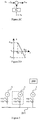
- the V/Q and f/P characteristics can be further illustrated in figure 2B .
- the active and reactive power reference references will be calculated according to a pre-defined operating point (P 0 , f 0 ,) and (Q 0 , V 0 ), the measured frequency and voltage f and V, and the droop factors K f and K V .
- the wind turbine can perform black start operation on its own following the islanding operation while does not rely on the power delivered from a generator of other wind turbine; this is helpful for reduction of communication between wind turbines.
- voltage and frequency stability concerning the V/f control of the selected first power source during the transients is increased due to active power and reactive power contributed by the selected second power source.
- Figure 3 illustrates a wind farm according to an embodiment of present invention.
- the wind farm 2 includes a wind farm controller 200, a cable 201, a multiple of wind turbines 1 according to figure 1 .
- Each of the wind turbines 1 further includes a third switch 112 arranged between the power output of its converter 101 and the cable 201 and a fourth measurement device 113 for measuring the voltage and frequency on its connection to the cable 201.
- the fourth measurement device 113 can be voltage and current sensors which can detect the voltage and current values at the wind turbine output point. Furthermore, based on these voltage and current values, calculate the voltage amplitude, system frequency, and wind turbine output active and reactive power, etc.
- the wind farm controller 200 is adapted for: choosing one wind turbine among the plurality of wind turbines 1. For example, the wind turbine 1 in the broken circle is chosen.
- the wind farm controller 200 further instructs the wind turbine controller 109 of the chosen wind turbine 1 (in the broken circle) to control to close the third switch 112 of the chosen wind turbine 1, and instructs the wind turbine controller 109 of the other wind turbine (not in the broken circle) to regulate the voltage and frequency of its first power source to approach measurements of the voltage and frequency on the cable by its fourth measurement device 113 so as to get the unchosen wind turbine to be synchronized with the chosen wind turbine.
- the wind turbine controller 109 of the other wind turbine is further adapted for controlling to close its third switch 112 following the regulation by the wind turbine controller 109 of the chosen wind turbine 1 (in the broken circle) upon synchronization of the chosen wind turbine and the unchosen wind turbine.
- the wind turbine controller 109 of the unchosen wind turbine which is synchronizing with the chosen wind turbine, can get the voltage difference between its own wind turbine and the cable.
- this voltage difference should follow three criteria before closing its third switch 112:
- FIG. 4 illustrates a wind farm according to an embodiment of present invention.
- the wind farm 3 includes a wind farm controller 300, a cable 301, a multiple of wind turbines 1 according to figure 1 , a substation level energy storage system 302, a substation level auxiliary equipment 303, a fourth switch 304 being arranged between the substation level energy storage system 302 and the cable 301, a fifth switch 305 being arranged between the substation level auxiliary equipment 303 and the cable 301, and fifth measurement device 306 for measuring the voltage and frequency on its connection to the cable 301.
- Each of the plurality of wind turbines 1 further includes a third switch 112 arranged between the power output of its converter 101 and the cable 301.
- the wind farm controller 300 is adapted for choosing one wind turbine among the plurality of wind turbines 1. For example, the wind turbine 1 in the broken circle is chosen.
- the wind farm controller 300 further instructs the wind turbine controller 109 of the chosen wind turbine 1 (in the broken circle) to close the third switch 112 of the chosen wind turbine 1, and instructs to regulate voltage and frequency of the substation level energy storage system 302 operating in V/f control mode to approach the measurements of the voltage and frequency on its connection to the cable 301 so as to get the substation level energy storage system 302 to be synchronized with the chosen wind turbine 1.
- the wind farm controller 300 then can control to close the fourth switch 304 and the fifth switch 305 upon the synchronization of the substation level energy storage system 302 and the chosen wind turbine 1. For example, based on the measured voltage and frequency on the cable 301, the energy storage system controller can get the voltage difference between its own energy storage system 302 and cable 301. In order to limit the rush current when closing the third switch 112 of energy storage system 302, this voltage difference should follow three criteria before closing this third switch 112:
- FIG. 5 illustrates a wind farm according to an embodiment of present invention.
- the wind farm 4 includes a wind farm controller 400, a cable 401, a sixth switch 402 being arranged between the cable 401 and main grid, a multiple of wind turbines 1 according to figure 1 .
- Each of the plurality of wind turbines 1 further includes a third switch 112 arranged between the power output of its converter 101 and the cable 401 and a fourth measurement device 113 for measuring the voltage and frequency on its connection to the cable 401.
- the wind farm controller 400 is adapted for: choosing at least one wind turbine among the plurality of wind turbines; controlling to close the sixth switch; instructing the wind turbine controller of the chosen wind turbine to regulate the voltage and frequency of its first power source to approach measurements of the voltage and frequency on the cable by its fourth measurement device; and controlling to close the third switch of the chosen wind turbine following the regulation by the wind turbine controller of the chosen wind turbine.
Description
- The invention relates to a method for black starting a wind turbine and a wind farm following islanding operation and restoring the wind farm and a wind turbine and a wind farm using the same, and more particularly to regulating a multiple of power sources in the wind turbine for powering its auxiliary equipment during the period of black start operation.
- It is well-known that in offshore wind farms, an independent emergency source of electrical power is to be provided for the power supply of emergency consumers (which can also be referred as auxiliary loads), e.g. lighting and signalling systems, etc., when the main power supply fails; and the supply time period should meet the requirement from e.g. several hours to several days for different loads. There are two feasible solutions to meet these requirements: using diesel generator sets as the emergency source, or using ESS as the emergency source.
- Patent
EP 2236821A1 discloses a method and a system for islanding operation of at least two wind turbines associated with a wind farm, wherein said wind farm is configured for providing power generated by wind turbines in said wind farm to a main grid and wherein the method comprises: detecting at least two or more deactivated wind turbines in said wind farm, said deactivated wind turbines being kept in stand-by operation by using its uninterrupted power supply (a sort of energy storage system) and being disconnected from said main grid; configuring at least one islanded local grid for electrically connecting said two or more deactivated wind turbines; activating at least one of said deactivated wind turbine using a black start operation; and, connecting said at least one activated wind turbine and at least one of said deactivated wind turbines to said local grid, said activated wind turbine acting as a power supply for said at least one deactivated wind turbine connected to said local grid. - Patent
WO 2014082757 A1 discusses a method involving connecting a converter unit to an electrical network on network side. The electrical energy generated by a generator is fed into the electrical network via converter unit. The electrical energy is drawn from an energy storage unit by an auxiliary energy unit for an adjustable period of time if converter unit and auxiliary energy unit are disconnected from electrical network. The electrical energy generated by generator is then drawn by the auxiliary energy unit via the converter unit. - However, each one of these references suffers from one or more of the following disadvantages: 1. it may lose voltage and frequency stability during the transients without appropriate coordination between operations of the generator and the energy storage system of the wind turbine; 2. it may lose voltage and frequency stability during the transients without appropriate coordination between operations of one wind turbine and another.
- It is therefore an objective of the invention to provide a method for black starting a wind turbine following islanding operation, wherein the wind turbine comprises auxiliary equipment, a generator, a converter electrically connectable to the generator, and an energy storage system, the generator is electrically connectable to the auxiliary equipment via the converter, the energy storage system is electrically connectable to the auxiliary equipment, the method including: measuring wind speed; if the measured wind speed is between the cut-in and cut-out wind speed of the wind turbine for a given time period, selecting the generator as a first power source to supply first power to the auxiliary equipment in V/f control mode and selecting the energy storage system as a second power source to adjust an amount of active power and reactive power fed to the auxiliary equipment by the first power source in consideration of amount of active power and reactive power demand suitable for powering the auxiliary equipment; otherwise selecting the energy storage system as a first power source to supply power to the auxiliary equipment in V/f control mode and selecting the generator as a second power source to adjust an amount of active power and reactive power fed to the auxiliary equipment by the first power source in consideration of the amount of active power and reactive power demand suitable for powering the auxiliary equipment; electrically connecting both of the selected first power source and the selected second power source to a power input terminal of the auxiliary equipment to supply the first power and the second power.
- According another aspect of present invention, it provides a wind turbine, including: a generator; a converter electrically connectable to the generator; an energy storage system; a first measurement device for measuring wind speed; a wind turbine controller; a first switch, being arranged between a power output of the converter and a power input of the auxiliary equipment; a second switch, being arranged between a power output of the energy storage system and the power input of the auxiliary equipment; following islanding operation of the wind turbine, the wind turbine controller is adapted for: if the measured wind speed is between the cut-in and cut-out wind speed of the wind turbine for a given time period, selecting the generator as a first power source to supply first power to the auxiliary equipment in V/f control mode and selecting the energy storage system as a second power source to adjust an amount of active power and reactive power fed to the auxiliary equipment by the first power source in consideration of amount of active power and reactive power demand suitable for powering the auxiliary equipment; otherwise selecting the energy storage system as a first power source to supply power to the auxiliary equipment in V/f control mode and selecting the generator as a second power source to adjust an amount of active power and reactive power fed to the auxiliary equipment by the first power source in consideration of the amount of active power and reactive power demand suitable for powering the auxiliary equipment; and controlling to close the first switch and the second switch to supply the first power and the second power to the auxiliary equipment.
- By coordinating the power supply by the selected first power source and the selected second power source of the wind turbine to the auxiliary equipment of the same wind turbine, the wind turbine can perform black start operation on its own following the islanding operation while does not rely on the power delivered from a generator of other wind turbine; this is helpful for reduction of communication between wind turbines. In addition, voltage and frequency stability concerning the V/f control of the selected first power source during the transients is increased due to active power and reactive power contributed by the selected second power source.
- The subject matter of the invention will be explained in more detail in the following text with reference to preferred exemplary embodiments which are illustrated in the drawings, in which:
-
Figure 1 illustrates a schematic of the main components of a wind turbine according to an embodiment of present invention; -
Figures 2A and 2B show voltage and frequency reference calculation under V/f control mode according to an embodiment of present invention; -
Figures 2C and 2D show active and reactive power reference calculation under P/Q control mode according to another embodiment of present invention; -
Figure 3 illustrates a wind farm according to an embodiment of present invention; -
Figure 4 illustrates a wind farm according to another embodiment of present invention; and -
Figure 5 illustrates a wind farm according to another embodiment of present invention. - The reference symbols used in the drawings, and their meanings, are listed in summary form in the list of reference symbols. In principle, identical parts are provided with the same reference symbols in the figures.
-
Figure 1 illustrates a schematic of the main components of a wind turbine according to an embodiment of present invention. As shown infigure 1 , thewind turbine 1 comprises agenerator 100, e.g. a permanent magnet generator or a synchronous or asynchronous type generator, which transforms the rotary energy of the blades in a variable frequency ac electrical power. The power output of the generator is electrically connectable to aconverter 101 to feed its output into theconverter 101 typically for converting the ac power into an AC power of a frequency used by the main grid. Theconverter 101, for example, can be an electrical power conversion apparatus comprising an AC/DC conversion for converting the AC power to a DC power and a DC/AC conversion for converting the DC power into an AC power of a frequency used by the main grid, namely a back to back converter. The power output of theconverter 101 is electrically connectable to a power input of auxiliary equipment 102 via afirst switch 103 and a transformer unit 104. The auxiliary equipment can be navigation lights used to signal the position of wind turbine, sensors used to get the operation parameters of wind turbine, communication apparatus used to send/receive the feedback/order with the substation, ventilation and heating equipment used to provide the required temperature for the equipment installed in wind turbine, for etc. Thefirst switch 103 can be a circuit breaker whose on/off status can be switched according to instruction by awind turbine controller 109. A power output of anenergy storage system 105 is electrically connectable to the power input of the auxiliary equipment 102 via asecond switch 106, e.g. a circuit breaker whose on/off status can be switched according instruction by thewind turbine controller 109. A first measurement device 107 can measure wind blowing smoothness, and the wind turbine converter can be started for power generation when the wind speed has reached the following range:
- Where ωmin and ωmax are the cut-in and cut-out wind speed of wind turbine, here we take a full power large scale offshore wind turbine as an example, then ωmin =3m/s and ωmax =20m/s, ω(t) is the wind speed during Δt time period, and Δt is decided according to the minimum time requirement for the auxiliary power supply of several important auxiliary load, here we define Δt=15 seconds. The
wind turbine controller 109 may collect operational data (e.g. power level, temperature, wind speed, conversion efficiency, etc.) and use these operational data to control the wind turbine such that optimal operation of the wind turbine is achieved. Further, thewind turbine controller 109 comprises a transmitter/receiver unit for providing for a data link 108 with the first measurement device 107, for providing instruction to thefirst switch 103 and thesecond switch 106 to change their switching statuses. - Islanding is a situation which may occur if a wind farm or part of the wind turbines of the wind farm becomes disconnected from the electrical grid, e.g. because of planned switching action or protective switching of a circuit breaker in the grid. For example after detection of a power failure circuit breakers may automatically disconnect one or more wind turbines from the grid. Thereafter, each disconnected wind turbine sets itself to a parking or standby state by stopping rotation of the blades by pitching the blades in the vane position. The standby state will last until the islanded wind farm can be reconnected to the grid. Following the islanding stage, the wind turbine is to be connected to the electrical grid; therefore, the wind turbine needs to operate in a black start mode in which its auxiliary equipment is supplied with power from a power source in the wind turbine.
- According to an embodiment of present invention as shown in
figure 1 , under the control of thewind turbine controller 109, thegenerator 100 and the energy storage system are selected as the power source for power the auxiliary equipment 102 of thewind turbine 1 operating in the black start mode. Where acting as the power source, the generator/energy storage system can either operate in voltage/frequency (V/f) control mode or in active/reactive power (P/Q) control mode. P/Q control mode can provide active/reactive power for the auxiliary load as a current source, which means P/Q control mode can support power for the system, but cannot provide stable voltage and frequency for the auxiliary load in islanding operation. Thus at least one generator/energy storage systems should work in V/f control mode, which can generate power for the auxiliary load as a voltage source, and provide voltage and frequency support for the system. Thewind turbine 1 comes into operation of black start mode following its islanding operation, thewind turbine controller 109 is adapted for: if the measured wind blowing smoothness degree is above a smoothness threshold, selecting thegenerator 100 as a first power source to supply first power to the auxiliary equipment 102 in V/f control mode and selecting theenergy storage system 105 as a second power source to adjust an amount of active power and reactive power fed to the auxiliary equipment 102 by the first power source in consideration of amount of active power and reactive power demand suitable for powering the auxiliary equipment 102; otherwise selecting theenergy storage system 105 as a first power source to supply power to the auxiliary equipment 102 in V/f control mode and selecting thegenerator 100 as a second power source to adjust an amount of active power and reactive power fed to the auxiliary equipment 102 by the first power source in consideration of the amount of active power and reactive power demand suitable for powering the auxiliary equipment 102. Upon the selection, thewind turbine controller 109 can control to close the first switch and the second switch to supply the first power and the second power to the auxiliary equipment. Preferably, the selected second power source supplies the second power in P/Q control mode. If thegenerator 100 is selected as the first power source: if theenergy storage system 105 capacity is enough for the auxiliary power supply with minimum power supply time period, the selected second power source supplies the second power in V/f control mode, otherwise the selected second power source supplies the second power in P/Q control model. Preferably, thewind turbine 1 further comprises: asecond measurement device 110 for measuring reactive and active power and voltage and frequency at output of the first power source; and athird measurement device 111 for measuring reactive power and active power and frequency and voltage at output of the second power; wherein: for the selected first power source in V/f control mode, the wind turbine controller is further adapted for calculating its voltage and frequency reference according to measurements of reactive and active power at output of the first power source; and for the selected second power source in P/Q control mode, the wind turbine controller is further adapted for calculating its active and reactive power reference according to measurements of the frequency and voltage at output of the second power. - For example, if the first/second power source is selected to work in V/f control mode, as illustrated in
figure 2A , the voltage and frequency references for this power source will be calculated according to a pre-defined operating point (V0, Q0) and (fe, P0), the measured reactive and active power output Q and P, and the droop factors KQ and KP. By doing this, we can protect this power source from running out of capacity. The V/Q and f/P characteristics can be further illustrated infigure 2B . - On the other hand, if the first/second power source is selected to work in P/Q control mode, as illustrated in
figure 2C , the active and reactive power reference references will be calculated according to a pre-defined operating point (P0, f0,) and (Q0, V0), the measured frequency and voltage f and V, and the droop factors Kf and KV. By doing this, we can ensure the stable operation of the system with multiple power sources operated together in an autonomous way. The P/f and Q/V characteristics can be further illustrated infigure 2D . By coordinating the power supply by the selected first power source and the selected second power source of the wind turbine to the auxiliary equipment of the same wind turbine, the wind turbine can perform black start operation on its own following the islanding operation while does not rely on the power delivered from a generator of other wind turbine; this is helpful for reduction of communication between wind turbines. In addition, voltage and frequency stability concerning the V/f control of the selected first power source during the transients is increased due to active power and reactive power contributed by the selected second power source. This is because, the big exchange of auxiliary load during the transients will lead to the exchange of system voltage amplitude and frequency, and then the power source with P/Q control will modify their output power according to this exchange of system voltage amplitude and frequency immediately, which can help to realize the system power balance, and furthermore, increase the system voltage and frequency stability. -
Figure 3 illustrates a wind farm according to an embodiment of present invention. As shown infigure 3 , the wind farm 2 includes awind farm controller 200, acable 201, a multiple ofwind turbines 1 according tofigure 1 . Each of thewind turbines 1 further includes athird switch 112 arranged between the power output of itsconverter 101 and thecable 201 and afourth measurement device 113 for measuring the voltage and frequency on its connection to thecable 201. For example, thefourth measurement device 113 can be voltage and current sensors which can detect the voltage and current values at the wind turbine output point. Furthermore, based on these voltage and current values, calculate the voltage amplitude, system frequency, and wind turbine output active and reactive power, etc. Following the islanding stage, the wind farm 2 is to be connected to the electrical grid; therefore, each of the multiple ofwind turbines 1 needs to operate in a black start mode in which its auxiliary equipment is supplied with power from a power source in the wind turbine. In the black start stage following islanding mode of the wind farm, thewind farm controller 200 is adapted for: choosing one wind turbine among the plurality ofwind turbines 1. For example, thewind turbine 1 in the broken circle is chosen. Thewind farm controller 200 further instructs thewind turbine controller 109 of the chosen wind turbine 1 (in the broken circle) to control to close thethird switch 112 of the chosenwind turbine 1, and instructs thewind turbine controller 109 of the other wind turbine (not in the broken circle) to regulate the voltage and frequency of its first power source to approach measurements of the voltage and frequency on the cable by itsfourth measurement device 113 so as to get the unchosen wind turbine to be synchronized with the chosen wind turbine. Thewind turbine controller 109 of the other wind turbine (not in the broken circle) is further adapted for controlling to close itsthird switch 112 following the regulation by thewind turbine controller 109 of the chosen wind turbine 1 (in the broken circle) upon synchronization of the chosen wind turbine and the unchosen wind turbine. For example, Based on the measured voltage and frequency on the cable, thewind turbine controller 109 of the unchosen wind turbine, which is synchronizing with the chosen wind turbine, can get the voltage difference between its own wind turbine and the cable. In order to limit the rush current when closing thethird switch 112 of this synchronizing wind turbine, this voltage difference should follow three criteria before closing its third switch 112: - Frequency difference: ωS = ωWT - ωCable ≈ 0
- Voltage vector amplitude difference: VS = VWT - VCable ≈ 0
- Phase angle difference: ∠ØS = ∠θWT - ∠θCable ≈ 0°
- By having the other wind turbines synchronize with the chosen wind turbine blacking start on its own, the inrush current evolved between the chosen and the unchosen during synchronization can be suppressed.
-
Figure 4 illustrates a wind farm according to an embodiment of present invention. As shown infigure 4 , the wind farm 3 includes awind farm controller 300, acable 301, a multiple ofwind turbines 1 according tofigure 1 , a substation levelenergy storage system 302, a substation levelauxiliary equipment 303, afourth switch 304 being arranged between the substation levelenergy storage system 302 and thecable 301, a fifth switch 305 being arranged between the substation levelauxiliary equipment 303 and thecable 301, andfifth measurement device 306 for measuring the voltage and frequency on its connection to thecable 301. Each of the plurality ofwind turbines 1 further includes athird switch 112 arranged between the power output of itsconverter 101 and thecable 301. Following the islanding stage, the wind farm 3 is to be connected to the electrical grid; therefore, each of the multiple ofwind turbines 1 needs to operate in a black start mode in which its auxiliary equipment is supplied with power from a power source in the wind turbine. In the black start stage following islanding mode of the wind farm, thewind farm controller 300 is adapted for choosing one wind turbine among the plurality ofwind turbines 1. For example, thewind turbine 1 in the broken circle is chosen. Thewind farm controller 300 further instructs thewind turbine controller 109 of the chosen wind turbine 1 (in the broken circle) to close thethird switch 112 of the chosenwind turbine 1, and instructs to regulate voltage and frequency of the substation levelenergy storage system 302 operating in V/f control mode to approach the measurements of the voltage and frequency on its connection to thecable 301 so as to get the substation levelenergy storage system 302 to be synchronized with the chosenwind turbine 1. Thewind farm controller 300 then can control to close thefourth switch 304 and the fifth switch 305 upon the synchronization of the substation levelenergy storage system 302 and the chosenwind turbine 1. For example, based on the measured voltage and frequency on thecable 301, the energy storage system controller can get the voltage difference between its ownenergy storage system 302 andcable 301. In order to limit the rush current when closing thethird switch 112 ofenergy storage system 302, this voltage difference should follow three criteria before closing this third switch 112: - Frequency difference: ωES = ωESS - ωCable ≈ 0
- Voltage vector amplitude difference: VES = VESS - VCable ≈ 0
- Phase angle difference: ∠ØES = ∠θEES - ∠θCable ≈ 0°
- By having the substation level energy storage system with the chosen wind turbine blacking start on its own, the inrush current evolved between them can be suppressed.
-
Figure 5 illustrates a wind farm according to an embodiment of present invention. As shown infigure 5 , the wind farm 4 includes awind farm controller 400, acable 401, asixth switch 402 being arranged between thecable 401 and main grid, a multiple ofwind turbines 1 according tofigure 1 . Each of the plurality ofwind turbines 1 further includes athird switch 112 arranged between the power output of itsconverter 101 and thecable 401 and afourth measurement device 113 for measuring the voltage and frequency on its connection to thecable 401. During restoration mode of the wind farm following its islanding mode, thewind farm controller 400 is adapted for: choosing at least one wind turbine among the plurality of wind turbines; controlling to close the sixth switch; instructing the wind turbine controller of the chosen wind turbine to regulate the voltage and frequency of its first power source to approach measurements of the voltage and frequency on the cable by its fourth measurement device; and controlling to close the third switch of the chosen wind turbine following the regulation by the wind turbine controller of the chosen wind turbine. - Though the present invention has been described on the basis of some preferred embodiments, those skilled in the art should appreciate that those embodiments should by no way limit the scope of the present invention. The scope of the present invention is defined by the accompanied claims.
Claims (14)
- A method for black starting a wind turbine following islanding operation, wherein the wind turbine comprises auxiliary equipment (102), a generator (100), a converter (101) electrically connectable to the generator (100), and an energy storage system (105), and wherein the generator (100) is electrically connectable to the auxiliary equipment (102) via the converter (101) and the energy storage system (105) is electrically connectable to the auxiliary equipment (102), the method including:Measuring a wind speed;
if the measured wind speed is between the cut-in and cut-out wind speed of the wind turbine (1) for a given time period (Δt), selecting the generator (100) as a first power source to supply first power to the auxiliary equipment (102) in V/f control mode and selecting the energy storage system (105) as a second power source to adjust an amount of active power and reactive power fed to the auxiliary equipment (102) by the first power source in consideration of the amount of active power and reactive power demand suitable for powering the auxiliary equipment (102);
otherwise selecting the energy storage system (105) as a first power source to supply power to the auxiliary equipment (102) in V/f control mode and selecting the generator (100) as a second power source to adjust an amount of active power and reactive power fed to the auxiliary equipment (102) by the first power source in consideration of the amount of active power and reactive power demand suitable for powering the auxiliary equipment (102); andelectrically connecting both of the selected first power source and the selected second power source to a power input terminal of the auxiliary equipment (102) to supply the first power and the second power. - The method according to claim 1, wherein:
the selected second power source supplies the second power in P/Q control mode. - The method according to claim 1 or 2, wherein:if the generator (100) is selected as the first power source,the method further includes:if the energy storage system (105) capacity is enough, the selected second power source supplies the second power in V/f control mode;otherwise the selected second power source supplies the second power in P/Q control mode.
- The method according to claim 1, wherein:for the selected first power source in V/f control mode, its voltage and frequency reference is calculated according to measurements of the reactive and active power at the output of the first power source; andfor the selected second power source in P/Q control mode, its active and reactive power reference is calculated according to measurements of the frequency and voltage at output of the second power source.
- A method for black starting a wind farm (2) during islanding mode, wherein the wind farm (2) includes a multiple of wind turbines (1) electrically connectable to each other via a cable (201, 301, 401), including:choosing one wind turbine (1) among the plurality of wind turbines (1);black starting the chosen wind turbine (1) according to the method according to any of claims 1 to 4;electrically connecting the chosen wind turbine (1) to the cable (201, 301, 401);regulating voltage and frequency of the first power source of another wind turbine (1) among the plurality of wind turbines (1) to approach measurements of the voltage and frequency on the cable (201, 301, 401); andelectrically connecting the other wind turbine (1) to the cable (201, 301, 401).
- A method for black starting a wind farm (2) during islanding mode, wherein the wind farm (2) includes a multiple of wind turbines (1), a substation level energy storage system (302) and a substation level auxiliary equipment (303) electrically connectable to each other via a cable (301), including:choosing one wind turbine (1) among the plurality of wind turbines (1);black starting the chosen wind turbine (1) according to the method according to any of claims 1 to 4;electrically connecting the chosen wind turbine (1) to the cable (301);regulating voltage and frequency of the substation level energy storage system (302) operation in V/f control mode to approach the measurements of the voltage and the frequency on the cable (301); andelectrically connecting the substation level energy storage system (302) and the substation level auxiliary equipment (303) to the cable (301).
- A method for restoring a wind farm (2) following islanding mode, wherein the wind farm (2) includes a multiple of wind turbines (1) electrically connectable to each other via a cable (401), including:choosing at least one wind turbine (1) among the plurality of wind turbines (1);black starting the chosen wind turbine (1) according to the method according to any of claims 1 to 4;electrically connecting a main grid to the cable (401);regulating voltage and frequency of the first power source of the chosen wind turbine (1) among the plurality of wind turbines (1) to approach measurements of the voltage and frequency on the cable (401); andelectrically connecting the chosen wind turbine (1) to the cable (401).
- A wind turbine (1), including:a generator (100);a converter (101) electrically connectable to the generator (100);an energy storage system (105);a first measurement device (107) for measuring a wind speed;a wind turbine controller (109);a first switch (103) arranged between a power output of the converter (101) and a power input of an auxiliary equipment (102);a second switch (106) arranged between a power output of the energy storage system (105) and the power input of the auxiliary equipment (102);following islanding operation of the wind turbine (1), the wind turbine controller (109) is adapted for:if the measured wind speed is between the cut-in and cut-out wind speed of the wind turbine (1) for a given time period (Δt), selecting the generator (100) as a first power source to supply first power to the auxiliary equipment (102) in V/f control mode and selecting the energy storage system (105) as a second power source to adjust an amount of active power and reactive power fed to the auxiliary equipment (102) by the first power source in consideration of the amount of active power and reactive power demand suitable for powering the auxiliary equipment (102);otherwise selecting the energy storage system (105) as a first power source to supply power to the auxiliary equipment (102) in V/f control mode and selecting the generator (100) as a second power source to adjust an amount of active power and reactive power fed to the auxiliary equipment (102) by the first power source in consideration of the amount of active power and reactive power demand suitable for powering the auxiliary equipment (102); andcontrolling to close the first switch (103) and the second switch (106) to supply the first power and the second power to the auxiliary equipment (102).
- The wind turbine (1) according to claim 8, wherein:
the selected second power source supplies the second power in P/Q control mode. - The wind turbine (1) according to claim 8 or 9, wherein:
if the generator (100) is selected as the first power source,if the energy storage system (105) capacity is enough, the selected second power source supplies the second power in V/f control mode;otherwise the selected second power source supplies the second power in P/Q control model. - The wind turbine (1) according to claim 8, further including:a second measurement device (110), for measuring reactive and active power and voltage and frequency at the output of the first power source; anda third measurement device (111), for measuring reactive and active power and frequency and voltage at the output of the second power source;wherein:for the selected first power source in V/f control mode, the wind turbine controller (109) is further adapted to calculating its voltage and frequency reference according to measurements of a reactive and active power at the output of the first power source; andfor the selected second power source in P/Q control mode, the wind turbine controller (109) is further adapted to calculating its active and reactive power reference according to measurements of the frequency and voltage at the output of the second power source.
- A wind farm (2), including:a wind farm controller (200, 300, 400);a cable (201, 301, 401);a multiple of wind turbines (1) according to any of claims 8 to 11, each of which further including a third switch (112) arranged between the power output of its converter (101) and the cable (201, 301, 401) and a fourth measurement device (113) for measuring the voltage and frequency on the cable (201, 301, 401);wherein:following islanding mode of the wind farm (2), the wind farm controller (200, 300, 400) is adapted to:choosing one wind turbine (1) among the plurality of wind turbines (1);instructing the wind turbine controller (109) of the chosen wind turbine (1) to control to close the third switch (112) of the chosen wind turbine (1); andinstructing the wind turbine controller (109) of the other wind turbine to regulate the voltage and frequency of its first power source to approach measurements of the voltage and frequency on the cable (201, 301, 401) by its fourth measurement device (113);the wind turbine controller (109) of the other wind turbine being further adapted to controlling to close the third switch (112) of the other wind turbine (1) following the regulation by the wind turbine controller (109) of the chosen wind turbine (1).
- A wind farm (2), including:a wind farm controller (300, 400);a cable (301, 401);a multiple of wind turbines (1) according to any of claims 8 to 11, each of which further including a third switch (112) arranged between the power output of its converter (101) and the cable (301, 401); anda fifth measurement device (306) for measuring the voltage and frequency on the cable (301, 401);a substation level energy storage system (302);a substation level auxiliary equipment (303);a fourth switch (304) arranged between the substation level energy storage system (302) and the cable (301, 401);a fifth switch arranged between the substation level auxiliary equipment (303) and the cable (301, 401);wherein:
following islanding mode of the wind farm (2), the wind farm controller (300, 400) is adapted to:choosing one wind turbine (1) among the plurality of wind turbines (1);instructing the wind turbine controller (109) of the chosen wind turbine (1) to close the third switch (112) of the chosen wind turbine (1); andinstructing to regulate voltage and frequency of the substation level energy storage system (302) operation in V/f control mode to approach the measurements of the voltage and frequency on the cable (301, 401); andcontrolling to close the fourth switch (304) and the fifth switch. - A wind farm (2), including:a wind farm controller (400);a cable (401);a sixth switch (402) arranged between the cable (401) and a main grid;a multiple of wind turbines (1) according to any of claims 8 to 11, each of which further including a third switch (112) arranged between the power output of its converter (101) and the cable (401) and a fourth measurement device (113) for measuring the voltage and frequency on the cable (401);wherein:
during restoration mode of the wind farm (2) following its islanding mode, the wind farm controller (400) is adapted to:choosing at least one wind turbine (1) among the plurality of wind turbines (1);controlling to close the sixth switch (402);instructing the wind turbine controller (109) of the chosen wind turbine (1) to regulate the voltage and frequency of its first power source to approach measurements of the voltage and frequency on the cable (401) by its fourth measurement device (113); andcontrolling to close the third switch (112) of the chosen wind turbine (1) following the regulation by the wind turbine controller (109) of the chosen wind turbine (1).
Applications Claiming Priority (1)
| Application Number | Priority Date | Filing Date | Title |
|---|---|---|---|
| PCT/CN2014/092019 WO2016082070A1 (en) | 2014-11-24 | 2014-11-24 | Method for black starting wind turbine, wind farm, and restoring wind farm and wind turbine, wind farm using the same |
Publications (3)
| Publication Number | Publication Date |
|---|---|
| EP3224925A1 EP3224925A1 (en) | 2017-10-04 |
| EP3224925A4 EP3224925A4 (en) | 2018-07-25 |
| EP3224925B1 true EP3224925B1 (en) | 2020-10-14 |
Family
ID=56073282
Family Applications (1)
| Application Number | Title | Priority Date | Filing Date |
|---|---|---|---|
| EP14906734.0A Active EP3224925B1 (en) | 2014-11-24 | 2014-11-24 | Method for black starting wind turbine, wind farm, and restoring wind farm and wind turbine, wind farm using the same |
Country Status (4)
| Country | Link |
|---|---|
| US (1) | US10156225B2 (en) |
| EP (1) | EP3224925B1 (en) |
| CN (1) | CN106471695B (en) |
| WO (1) | WO2016082070A1 (en) |
Families Citing this family (37)
| Publication number | Priority date | Publication date | Assignee | Title |
|---|---|---|---|---|
| DE102013222452A1 (en) * | 2013-11-05 | 2015-05-07 | Wobben Properties Gmbh | Method for operating a wind energy plant |
| WO2016101130A1 (en) * | 2014-12-23 | 2016-06-30 | Abb Technology Ltd | Method and controller for coordinating control of wind farm during disconnection to utility grid |
| CN106300407B (en) * | 2015-05-26 | 2020-03-17 | 通用电气公司 | Power generation system |
| DE102016105662A1 (en) * | 2016-03-29 | 2017-10-05 | Wobben Properties Gmbh | Method for feeding electrical power into an electrical supply network with a wind farm and wind farm |
| DE102016106215A1 (en) | 2016-04-05 | 2017-10-05 | Wobben Properties Gmbh | Method and wind turbine for feeding electrical power |
| CN106451562A (en) * | 2016-12-16 | 2017-02-22 | 北京索英电气技术有限公司 | Black-start system and method for wind and light power storage station |
| DE102017106338A1 (en) * | 2017-03-23 | 2018-09-27 | Wobben Properties Gmbh | Method for starting a power generation network |
| CN107104463B (en) * | 2017-06-28 | 2019-10-18 | 南京理工大学 | Converter station considers idle active input amount optimization method during black starting-up |
| CN107294130B (en) * | 2017-06-28 | 2020-01-17 | 东北电力大学 | Wind storage power generation black start system and energy storage configuration method thereof |
| EP3471231A1 (en) * | 2017-10-13 | 2019-04-17 | Ørsted Wind Power A/S | A method for black-starting an electrical grid |
| CN107947246B (en) * | 2017-11-15 | 2020-01-10 | 清华大学 | Wind power generation index distribution and increased power evaluation method considering frequency modulation and increased power |
| CN109995036B (en) * | 2017-12-29 | 2024-03-22 | 中国电力科学研究院有限公司 | Automatic black start path optimizing method and system for wind-solar energy storage isolated network |
| CN112272907A (en) * | 2018-04-09 | 2021-01-26 | 乌本产权有限公司 | Method for connecting a power transformer to a power grid |
| CN108377004B (en) * | 2018-04-23 | 2024-03-15 | 华北电力科学研究院有限责任公司 | Wind-storage coordination frequency modulation method and system based on virtual synchronous machine |
| US10697432B2 (en) * | 2018-08-03 | 2020-06-30 | General Electric Company | Wind farm energy storage device for curtailment and auxiliary loads use |
| US11255314B2 (en) * | 2018-09-10 | 2022-02-22 | General Electric Company | Energy audit tool for a wind turbine power system |
| CN110350554B (en) * | 2019-07-12 | 2022-03-29 | 东北电力大学 | Wind storage system auxiliary power grid primary frequency modulation control method based on series-parallel structure |
| CN110957805B (en) * | 2019-11-20 | 2021-10-26 | 中国能源建设集团广东省电力设计研究院有限公司 | Black start power supply control device and method based on extension unit |
| CN112881820A (en) * | 2019-11-29 | 2021-06-01 | 西门子歌美飒可再生能源创新与技术有限公司 | Power system and method of performing a test procedure of a power system of a wind turbine |
| US11749997B2 (en) * | 2020-06-05 | 2023-09-05 | Eaton Intelligent Power Limited | Synchronization of electrical power grids |
| CN111614124B (en) * | 2020-06-16 | 2022-02-15 | 上海电气风电集团股份有限公司 | Novel power supply method for large island operation mode of offshore wind farm |
| US11680558B2 (en) | 2020-09-16 | 2023-06-20 | General Electric Company | Grid-forming control of inverter-based resource using virtual impedance |
| US11624350B2 (en) | 2020-09-18 | 2023-04-11 | General Electric Company | System and method for providing grid-forming control of an inverter-based resource |
| US11506173B2 (en) | 2020-12-07 | 2022-11-22 | General Electric Company | System and method for providing grid-forming control for a double-fed wind turbine generator using virtual impedance |
| US11626736B2 (en) | 2020-12-07 | 2023-04-11 | General Electric Company | Method for controlling negative-sequence current for grid-forming controls of inverter-based resources |
| US11671039B2 (en) | 2020-12-10 | 2023-06-06 | General Electric Renovables Espana, S.L. | System and method for operating an asynchronous inverter-based resource as a virtual synchronous machine to provide grid-forming control thereof |
| US11456645B2 (en) | 2020-12-10 | 2022-09-27 | General Electric Renovables Espana, S.L. | System and method for operating an asynchronous inverter-based resource as a virtual synchronous machine with storage |
| US11411520B1 (en) | 2021-02-25 | 2022-08-09 | General Electric Company | System and method for providing grid-forming control for a double-fed wind turbine generator |
| CN113067369B (en) * | 2021-02-25 | 2022-11-15 | 中国能源建设集团广东省电力设计研究院有限公司 | Configuration method of diesel generator set of offshore wind power combined power generation and supply system |
| CN112952826A (en) * | 2021-04-07 | 2021-06-11 | 阳光电源股份有限公司 | Distributed wind power storage station and black start method thereof |
| US11715958B2 (en) | 2021-07-29 | 2023-08-01 | General Electric Company | System and method for power control of an inverter-based resource with a grid-forming converter |
| US11632065B2 (en) | 2021-08-12 | 2023-04-18 | General Electric Company | System and method for providing grid-forming control of an inverter-based resource |
| EP4142094A1 (en) * | 2021-08-17 | 2023-03-01 | Vestas Wind Systems A/S | Methods and systems for power control in a non-exporting mode of operation |
| US11870386B2 (en) | 2021-10-19 | 2024-01-09 | General Electric Company | System and methods for controlling a power generating asset having a non-deliverable component of a total power output |
| WO2023079145A1 (en) * | 2021-11-08 | 2023-05-11 | Siemens Gamesa Renewable Energy A/S | Transitioning of wind turbine operation |
| US11870267B2 (en) | 2021-11-29 | 2024-01-09 | General Electric Company | System and method for constraining grid-induced power deviations from grid-forming inverter-based resources |
| US11843252B2 (en) | 2021-11-30 | 2023-12-12 | General Electric Company | System and method for damping sub-synchronous control interactions in a grid-forming inverter-based resource |
Family Cites Families (18)
| Publication number | Priority date | Publication date | Assignee | Title |
|---|---|---|---|---|
| ES2265771B1 (en) * | 2005-07-22 | 2008-01-16 | GAMESA INNOVATION & TECHNOLOGY, S.L. | METHOD FOR MAINTAINING THE COMPONENTS OF A WIND TURBINE AND A WIND TURBINE WITH COMPONENTS THAT ALLOW OPERATING MAINTENANCE. |
| DE102005038558A1 (en) | 2005-08-12 | 2007-02-15 | Repower Systems Ag | Method for operating a wind energy plant park and wind energy plant park |
| US7391126B2 (en) * | 2006-06-30 | 2008-06-24 | General Electric Company | Systems and methods for an integrated electrical sub-system powered by wind energy |
| US7394166B2 (en) * | 2006-10-04 | 2008-07-01 | General Electric Company | Method, apparatus and computer program product for wind turbine start-up and operation without grid power |
| EP1993184B2 (en) * | 2007-05-14 | 2024-04-24 | Siemens Gamesa Renewable Energy A/S | Method of start up at least a part of a wind power plant, wind power plant and use of the wind power plant |
| JP4834691B2 (en) * | 2008-05-09 | 2011-12-14 | 株式会社日立製作所 | Wind power generation system |
| US8008794B2 (en) * | 2008-07-16 | 2011-08-30 | General Electric Company | Use of pitch battery power to start wind turbine during grid loss/black start capability |
| ES2618029T3 (en) * | 2009-04-03 | 2017-06-20 | Xemc Darwind B.V. | Operation of an electric park connected in an independent power grid |
| JP5433682B2 (en) * | 2010-10-29 | 2014-03-05 | 三菱重工業株式会社 | Wind turbine generator control device, wind farm, and wind turbine generator control method |
| EP2503146B1 (en) | 2011-03-21 | 2013-12-18 | Siemens Aktiengesellschaft | Method and arrangement for controlling an operation of an electric energy production facility during a disconnection to a utility grid. |
| US9509141B2 (en) * | 2011-04-15 | 2016-11-29 | Siemens Aktiengesellschaft | Black start of wind turbine devices |
| EP2565443A1 (en) * | 2011-09-05 | 2013-03-06 | XEMC Darwind B.V. | Generating auxiliary power for a wind turbine |
| CA2861571C (en) * | 2012-01-17 | 2020-07-07 | Ecamion Inc. | A control, protection and power management system for an energy storage system |
| DE102012204239A1 (en) | 2012-03-16 | 2013-09-19 | Wobben Properties Gmbh | Method for controlling a wind energy plant |
| EP2926003B1 (en) * | 2012-11-27 | 2016-06-08 | ABB Technology AG | Method for operating an energy installation, and an energy system comprising such energy installations |
| CN103259475B (en) * | 2013-04-22 | 2015-10-21 | 华中科技大学 | Based on frequency synchronization method and device in the double fed induction generators of power-balance |
| CN104143832B (en) * | 2013-05-07 | 2016-08-24 | 通用电气公司 | For collapse of voltage condition detection and the system and method for control |
| EP2824323A1 (en) * | 2013-07-12 | 2015-01-14 | Siemens Aktiengesellschaft | Operating wind turbines as damping loads |
-
2014
- 2014-11-24 WO PCT/CN2014/092019 patent/WO2016082070A1/en active Application Filing
- 2014-11-24 EP EP14906734.0A patent/EP3224925B1/en active Active
- 2014-11-24 CN CN201480080253.2A patent/CN106471695B/en active Active
-
2016
- 2016-11-23 US US15/360,108 patent/US10156225B2/en active Active
Non-Patent Citations (1)
| Title |
|---|
| None * |
Also Published As
| Publication number | Publication date |
|---|---|
| CN106471695A (en) | 2017-03-01 |
| US20170074244A1 (en) | 2017-03-16 |
| EP3224925A1 (en) | 2017-10-04 |
| WO2016082070A1 (en) | 2016-06-02 |
| US10156225B2 (en) | 2018-12-18 |
| CN106471695B (en) | 2019-05-14 |
| EP3224925A4 (en) | 2018-07-25 |
Similar Documents
| Publication | Publication Date | Title |
|---|---|---|
| US10156225B2 (en) | Method for black starting wind turbine, wind farm, and restoring wind farm and wind turbine, wind farm using the same | |
| US10374429B2 (en) | Islanding a plurality of grid tied power converters | |
| JP5308511B2 (en) | Output control method and output control apparatus for wind power generation equipment | |
| US11070057B2 (en) | Method for starting an energy generation network | |
| EP2587609B1 (en) | Power supply device and method | |
| US20150249413A1 (en) | System and method for adjusting current regulator gains applied within a power generation system | |
| CN109792152B (en) | Non-master distributed power transmission control | |
| TW201351846A (en) | System, method, and apparatus for powering equipment during a low voltage event | |
| EP3042429A1 (en) | Redundant point of common coupling (pcc) to reduce risk of microgrid's islanding | |
| KR101196729B1 (en) | Apparatus for actively controlling synchronization of microgrid and method thereof | |
| JP2022084512A (en) | Intelligent switch device and power generating system | |
| WO2021205700A1 (en) | Power conversion device | |
| JP2018207574A (en) | Microgrid control system and method | |
| KR20160080914A (en) | Micro Grid System for Grid-Connection of Energy Storage System and Method for Grid-Connection Energy Storage System USING THE SAME | |
| JP6914358B2 (en) | Separation system formation detection method | |
| US20240093670A1 (en) | Operating a wind turbine in an off-grid stand-alone mode | |
| NZ734661B2 (en) | Islanding a plurality of grid tied power converters |
Legal Events
| Date | Code | Title | Description |
|---|---|---|---|
| STAA | Information on the status of an ep patent application or granted ep patent |
Free format text: STATUS: THE INTERNATIONAL PUBLICATION HAS BEEN MADE |
|
| PUAI | Public reference made under article 153(3) epc to a published international application that has entered the european phase |
Free format text: ORIGINAL CODE: 0009012 |
|
| STAA | Information on the status of an ep patent application or granted ep patent |
Free format text: STATUS: REQUEST FOR EXAMINATION WAS MADE |
|
| 17P | Request for examination filed |
Effective date: 20170626 |
|
| AK | Designated contracting states |
Kind code of ref document: A1 Designated state(s): AL AT BE BG CH CY CZ DE DK EE ES FI FR GB GR HR HU IE IS IT LI LT LU LV MC MK MT NL NO PL PT RO RS SE SI SK SM TR |
|
| AX | Request for extension of the european patent |
Extension state: BA ME |
|
| DAX | Request for extension of the european patent (deleted) | ||
| A4 | Supplementary search report drawn up and despatched |
Effective date: 20180625 |
|
| RIC1 | Information provided on ipc code assigned before grant |
Ipc: H02P 9/00 20060101ALI20180619BHEP Ipc: F03D 9/00 20160101ALI20180619BHEP Ipc: H02J 3/38 20060101AFI20180619BHEP |
|
| GRAP | Despatch of communication of intention to grant a patent |
Free format text: ORIGINAL CODE: EPIDOSNIGR1 |
|
| STAA | Information on the status of an ep patent application or granted ep patent |
Free format text: STATUS: GRANT OF PATENT IS INTENDED |
|
| INTG | Intention to grant announced |
Effective date: 20200511 |
|
| GRAS | Grant fee paid |
Free format text: ORIGINAL CODE: EPIDOSNIGR3 |
|
| GRAA | (expected) grant |
Free format text: ORIGINAL CODE: 0009210 |
|
| STAA | Information on the status of an ep patent application or granted ep patent |
Free format text: STATUS: THE PATENT HAS BEEN GRANTED |
|
| AK | Designated contracting states |
Kind code of ref document: B1 Designated state(s): AL AT BE BG CH CY CZ DE DK EE ES FI FR GB GR HR HU IE IS IT LI LT LU LV MC MK MT NL NO PL PT RO RS SE SI SK SM TR |
|
| REG | Reference to a national code |
Ref country code: GB Ref legal event code: FG4D |
|
| REG | Reference to a national code |
Ref country code: AT Ref legal event code: REF Ref document number: 1324516 Country of ref document: AT Kind code of ref document: T Effective date: 20201015 Ref country code: CH Ref legal event code: EP |
|
| REG | Reference to a national code |
Ref country code: DE Ref legal event code: R096 Ref document number: 602014071334 Country of ref document: DE |
|
| REG | Reference to a national code |
Ref country code: IE Ref legal event code: FG4D |
|
| REG | Reference to a national code |
Ref country code: AT Ref legal event code: MK05 Ref document number: 1324516 Country of ref document: AT Kind code of ref document: T Effective date: 20201014 |
|
| REG | Reference to a national code |
Ref country code: NL Ref legal event code: MP Effective date: 20201014 |
|
| PG25 | Lapsed in a contracting state [announced via postgrant information from national office to epo] |
Ref country code: RS Free format text: LAPSE BECAUSE OF FAILURE TO SUBMIT A TRANSLATION OF THE DESCRIPTION OR TO PAY THE FEE WITHIN THE PRESCRIBED TIME-LIMIT Effective date: 20201014 Ref country code: FI Free format text: LAPSE BECAUSE OF FAILURE TO SUBMIT A TRANSLATION OF THE DESCRIPTION OR TO PAY THE FEE WITHIN THE PRESCRIBED TIME-LIMIT Effective date: 20201014 Ref country code: PT Free format text: LAPSE BECAUSE OF FAILURE TO SUBMIT A TRANSLATION OF THE DESCRIPTION OR TO PAY THE FEE WITHIN THE PRESCRIBED TIME-LIMIT Effective date: 20210215 Ref country code: NL Free format text: LAPSE BECAUSE OF FAILURE TO SUBMIT A TRANSLATION OF THE DESCRIPTION OR TO PAY THE FEE WITHIN THE PRESCRIBED TIME-LIMIT Effective date: 20201014 Ref country code: NO Free format text: LAPSE BECAUSE OF FAILURE TO SUBMIT A TRANSLATION OF THE DESCRIPTION OR TO PAY THE FEE WITHIN THE PRESCRIBED TIME-LIMIT Effective date: 20210114 Ref country code: GR Free format text: LAPSE BECAUSE OF FAILURE TO SUBMIT A TRANSLATION OF THE DESCRIPTION OR TO PAY THE FEE WITHIN THE PRESCRIBED TIME-LIMIT Effective date: 20210115 |
|
| REG | Reference to a national code |
Ref country code: LT Ref legal event code: MG4D |
|
| PG25 | Lapsed in a contracting state [announced via postgrant information from national office to epo] |
Ref country code: BG Free format text: LAPSE BECAUSE OF FAILURE TO SUBMIT A TRANSLATION OF THE DESCRIPTION OR TO PAY THE FEE WITHIN THE PRESCRIBED TIME-LIMIT Effective date: 20210114 Ref country code: ES Free format text: LAPSE BECAUSE OF FAILURE TO SUBMIT A TRANSLATION OF THE DESCRIPTION OR TO PAY THE FEE WITHIN THE PRESCRIBED TIME-LIMIT Effective date: 20201014 Ref country code: AT Free format text: LAPSE BECAUSE OF FAILURE TO SUBMIT A TRANSLATION OF THE DESCRIPTION OR TO PAY THE FEE WITHIN THE PRESCRIBED TIME-LIMIT Effective date: 20201014 Ref country code: SE Free format text: LAPSE BECAUSE OF FAILURE TO SUBMIT A TRANSLATION OF THE DESCRIPTION OR TO PAY THE FEE WITHIN THE PRESCRIBED TIME-LIMIT Effective date: 20201014 Ref country code: IS Free format text: LAPSE BECAUSE OF FAILURE TO SUBMIT A TRANSLATION OF THE DESCRIPTION OR TO PAY THE FEE WITHIN THE PRESCRIBED TIME-LIMIT Effective date: 20210214 Ref country code: PL Free format text: LAPSE BECAUSE OF FAILURE TO SUBMIT A TRANSLATION OF THE DESCRIPTION OR TO PAY THE FEE WITHIN THE PRESCRIBED TIME-LIMIT Effective date: 20201014 Ref country code: LV Free format text: LAPSE BECAUSE OF FAILURE TO SUBMIT A TRANSLATION OF THE DESCRIPTION OR TO PAY THE FEE WITHIN THE PRESCRIBED TIME-LIMIT Effective date: 20201014 |
|
| PG25 | Lapsed in a contracting state [announced via postgrant information from national office to epo] |
Ref country code: HR Free format text: LAPSE BECAUSE OF FAILURE TO SUBMIT A TRANSLATION OF THE DESCRIPTION OR TO PAY THE FEE WITHIN THE PRESCRIBED TIME-LIMIT Effective date: 20201014 |
|
| REG | Reference to a national code |
Ref country code: CH Ref legal event code: PL |
|
| REG | Reference to a national code |
Ref country code: DE Ref legal event code: R097 Ref document number: 602014071334 Country of ref document: DE |
|
| PG25 | Lapsed in a contracting state [announced via postgrant information from national office to epo] |
Ref country code: SM Free format text: LAPSE BECAUSE OF FAILURE TO SUBMIT A TRANSLATION OF THE DESCRIPTION OR TO PAY THE FEE WITHIN THE PRESCRIBED TIME-LIMIT Effective date: 20201014 Ref country code: EE Free format text: LAPSE BECAUSE OF FAILURE TO SUBMIT A TRANSLATION OF THE DESCRIPTION OR TO PAY THE FEE WITHIN THE PRESCRIBED TIME-LIMIT Effective date: 20201014 Ref country code: CZ Free format text: LAPSE BECAUSE OF FAILURE TO SUBMIT A TRANSLATION OF THE DESCRIPTION OR TO PAY THE FEE WITHIN THE PRESCRIBED TIME-LIMIT Effective date: 20201014 Ref country code: RO Free format text: LAPSE BECAUSE OF FAILURE TO SUBMIT A TRANSLATION OF THE DESCRIPTION OR TO PAY THE FEE WITHIN THE PRESCRIBED TIME-LIMIT Effective date: 20201014 Ref country code: SK Free format text: LAPSE BECAUSE OF FAILURE TO SUBMIT A TRANSLATION OF THE DESCRIPTION OR TO PAY THE FEE WITHIN THE PRESCRIBED TIME-LIMIT Effective date: 20201014 Ref country code: LU Free format text: LAPSE BECAUSE OF NON-PAYMENT OF DUE FEES Effective date: 20201124 Ref country code: MC Free format text: LAPSE BECAUSE OF FAILURE TO SUBMIT A TRANSLATION OF THE DESCRIPTION OR TO PAY THE FEE WITHIN THE PRESCRIBED TIME-LIMIT Effective date: 20201014 Ref country code: LT Free format text: LAPSE BECAUSE OF FAILURE TO SUBMIT A TRANSLATION OF THE DESCRIPTION OR TO PAY THE FEE WITHIN THE PRESCRIBED TIME-LIMIT Effective date: 20201014 |
|
| REG | Reference to a national code |
Ref country code: BE Ref legal event code: MM Effective date: 20201130 |
|
| PLBE | No opposition filed within time limit |
Free format text: ORIGINAL CODE: 0009261 |
|
| STAA | Information on the status of an ep patent application or granted ep patent |
Free format text: STATUS: NO OPPOSITION FILED WITHIN TIME LIMIT |
|
| PG25 | Lapsed in a contracting state [announced via postgrant information from national office to epo] |
Ref country code: DK Free format text: LAPSE BECAUSE OF FAILURE TO SUBMIT A TRANSLATION OF THE DESCRIPTION OR TO PAY THE FEE WITHIN THE PRESCRIBED TIME-LIMIT Effective date: 20201014 Ref country code: CH Free format text: LAPSE BECAUSE OF NON-PAYMENT OF DUE FEES Effective date: 20201130 Ref country code: LI Free format text: LAPSE BECAUSE OF NON-PAYMENT OF DUE FEES Effective date: 20201130 |
|
| 26N | No opposition filed |
Effective date: 20210715 |
|
| PG25 | Lapsed in a contracting state [announced via postgrant information from national office to epo] |
Ref country code: AL Free format text: LAPSE BECAUSE OF FAILURE TO SUBMIT A TRANSLATION OF THE DESCRIPTION OR TO PAY THE FEE WITHIN THE PRESCRIBED TIME-LIMIT Effective date: 20201014 Ref country code: IE Free format text: LAPSE BECAUSE OF NON-PAYMENT OF DUE FEES Effective date: 20201124 Ref country code: IT Free format text: LAPSE BECAUSE OF FAILURE TO SUBMIT A TRANSLATION OF THE DESCRIPTION OR TO PAY THE FEE WITHIN THE PRESCRIBED TIME-LIMIT Effective date: 20201014 |
|
| PG25 | Lapsed in a contracting state [announced via postgrant information from national office to epo] |
Ref country code: SI Free format text: LAPSE BECAUSE OF FAILURE TO SUBMIT A TRANSLATION OF THE DESCRIPTION OR TO PAY THE FEE WITHIN THE PRESCRIBED TIME-LIMIT Effective date: 20201014 |
|
| PG25 | Lapsed in a contracting state [announced via postgrant information from national office to epo] |
Ref country code: IS Free format text: LAPSE BECAUSE OF FAILURE TO SUBMIT A TRANSLATION OF THE DESCRIPTION OR TO PAY THE FEE WITHIN THE PRESCRIBED TIME-LIMIT Effective date: 20210214 Ref country code: TR Free format text: LAPSE BECAUSE OF FAILURE TO SUBMIT A TRANSLATION OF THE DESCRIPTION OR TO PAY THE FEE WITHIN THE PRESCRIBED TIME-LIMIT Effective date: 20201014 Ref country code: MT Free format text: LAPSE BECAUSE OF FAILURE TO SUBMIT A TRANSLATION OF THE DESCRIPTION OR TO PAY THE FEE WITHIN THE PRESCRIBED TIME-LIMIT Effective date: 20201014 Ref country code: CY Free format text: LAPSE BECAUSE OF FAILURE TO SUBMIT A TRANSLATION OF THE DESCRIPTION OR TO PAY THE FEE WITHIN THE PRESCRIBED TIME-LIMIT Effective date: 20201014 |
|
| PG25 | Lapsed in a contracting state [announced via postgrant information from national office to epo] |
Ref country code: MK Free format text: LAPSE BECAUSE OF FAILURE TO SUBMIT A TRANSLATION OF THE DESCRIPTION OR TO PAY THE FEE WITHIN THE PRESCRIBED TIME-LIMIT Effective date: 20201014 |
|
| PG25 | Lapsed in a contracting state [announced via postgrant information from national office to epo] |
Ref country code: BE Free format text: LAPSE BECAUSE OF NON-PAYMENT OF DUE FEES Effective date: 20201130 |
|
| PGFP | Annual fee paid to national office [announced via postgrant information from national office to epo] |
Ref country code: GB Payment date: 20231123 Year of fee payment: 10 |
|
| PGFP | Annual fee paid to national office [announced via postgrant information from national office to epo] |
Ref country code: FR Payment date: 20231120 Year of fee payment: 10 Ref country code: DE Payment date: 20231121 Year of fee payment: 10 |