EP3224504B1 - Method of forming a flexible carbon composite self-lubricating seal - Google Patents
Method of forming a flexible carbon composite self-lubricating seal Download PDFInfo
- Publication number
- EP3224504B1 EP3224504B1 EP15862719.0A EP15862719A EP3224504B1 EP 3224504 B1 EP3224504 B1 EP 3224504B1 EP 15862719 A EP15862719 A EP 15862719A EP 3224504 B1 EP3224504 B1 EP 3224504B1
- Authority
- EP
- European Patent Office
- Prior art keywords
- carbon composite
- carbon
- annular seal
- flexible
- graphite
- Prior art date
- Legal status (The legal status is an assumption and is not a legal conclusion. Google has not performed a legal analysis and makes no representation as to the accuracy of the status listed.)
- Active
Links
- OKTJSMMVPCPJKN-UHFFFAOYSA-N Carbon Chemical compound [C] OKTJSMMVPCPJKN-UHFFFAOYSA-N 0.000 title claims description 250
- 229910052799 carbon Inorganic materials 0.000 title claims description 183
- 239000002131 composite material Substances 0.000 title claims description 121
- 238000000034 method Methods 0.000 title claims description 34
- 239000011230 binding agent Substances 0.000 claims description 77
- 229910002804 graphite Inorganic materials 0.000 claims description 67
- 239000010439 graphite Substances 0.000 claims description 67
- 239000000203 mixture Substances 0.000 claims description 39
- 239000002105 nanoparticle Substances 0.000 claims description 25
- 229910052751 metal Inorganic materials 0.000 claims description 23
- 239000002184 metal Substances 0.000 claims description 23
- 238000010438 heat treatment Methods 0.000 claims description 21
- 238000002844 melting Methods 0.000 claims description 8
- 230000008018 melting Effects 0.000 claims description 8
- 238000002156 mixing Methods 0.000 claims description 8
- 239000000843 powder Substances 0.000 claims description 6
- 229910001092 metal group alloy Inorganic materials 0.000 claims description 3
- 238000003754 machining Methods 0.000 claims description 2
- 230000002401 inhibitory effect Effects 0.000 claims 1
- 150000001721 carbon Chemical class 0.000 description 39
- XEEYBQQBJWHFJM-UHFFFAOYSA-N Iron Chemical compound [Fe] XEEYBQQBJWHFJM-UHFFFAOYSA-N 0.000 description 13
- PXHVJJICTQNCMI-UHFFFAOYSA-N Nickel Chemical compound [Ni] PXHVJJICTQNCMI-UHFFFAOYSA-N 0.000 description 13
- 229910045601 alloy Inorganic materials 0.000 description 12
- 239000000956 alloy Substances 0.000 description 12
- 150000001247 metal acetylides Chemical class 0.000 description 12
- 230000008569 process Effects 0.000 description 11
- 239000000126 substance Substances 0.000 description 11
- 239000000463 material Substances 0.000 description 10
- 229910021382 natural graphite Inorganic materials 0.000 description 10
- 238000007789 sealing Methods 0.000 description 10
- 229910052742 iron Inorganic materials 0.000 description 7
- 229910052759 nickel Inorganic materials 0.000 description 7
- 239000008188 pellet Substances 0.000 description 7
- 239000011651 chromium Substances 0.000 description 6
- 230000006835 compression Effects 0.000 description 6
- 238000007906 compression Methods 0.000 description 6
- 239000010949 copper Substances 0.000 description 6
- 229920001971 elastomer Polymers 0.000 description 6
- 239000000806 elastomer Substances 0.000 description 6
- -1 heat conductivity Chemical compound 0.000 description 6
- 239000006104 solid solution Substances 0.000 description 6
- 229910052804 chromium Inorganic materials 0.000 description 5
- 229910052802 copper Inorganic materials 0.000 description 5
- 238000001125 extrusion Methods 0.000 description 5
- 239000002245 particle Substances 0.000 description 5
- 238000001878 scanning electron micrograph Methods 0.000 description 5
- 230000035939 shock Effects 0.000 description 5
- 239000000243 solution Substances 0.000 description 5
- 229910052719 titanium Inorganic materials 0.000 description 5
- 239000010936 titanium Substances 0.000 description 5
- VYZAMTAEIAYCRO-UHFFFAOYSA-N Chromium Chemical compound [Cr] VYZAMTAEIAYCRO-UHFFFAOYSA-N 0.000 description 4
- RYGMFSIKBFXOCR-UHFFFAOYSA-N Copper Chemical compound [Cu] RYGMFSIKBFXOCR-UHFFFAOYSA-N 0.000 description 4
- 229910018487 Ni—Cr Inorganic materials 0.000 description 4
- VYPSYNLAJGMNEJ-UHFFFAOYSA-N Silicium dioxide Chemical compound O=[Si]=O VYPSYNLAJGMNEJ-UHFFFAOYSA-N 0.000 description 4
- RTAQQCXQSZGOHL-UHFFFAOYSA-N Titanium Chemical compound [Ti] RTAQQCXQSZGOHL-UHFFFAOYSA-N 0.000 description 4
- 229910052782 aluminium Inorganic materials 0.000 description 4
- 229910021383 artificial graphite Inorganic materials 0.000 description 4
- VNNRSPGTAMTISX-UHFFFAOYSA-N chromium nickel Chemical compound [Cr].[Ni] VNNRSPGTAMTISX-UHFFFAOYSA-N 0.000 description 4
- 238000000605 extraction Methods 0.000 description 4
- WPBNNNQJVZRUHP-UHFFFAOYSA-L manganese(2+);methyl n-[[2-(methoxycarbonylcarbamothioylamino)phenyl]carbamothioyl]carbamate;n-[2-(sulfidocarbothioylamino)ethyl]carbamodithioate Chemical compound [Mn+2].[S-]C(=S)NCCNC([S-])=S.COC(=O)NC(=S)NC1=CC=CC=C1NC(=S)NC(=O)OC WPBNNNQJVZRUHP-UHFFFAOYSA-L 0.000 description 4
- 229910052750 molybdenum Inorganic materials 0.000 description 4
- 229910052758 niobium Inorganic materials 0.000 description 4
- 239000010955 niobium Substances 0.000 description 4
- 239000004033 plastic Substances 0.000 description 4
- 229920003023 plastic Polymers 0.000 description 4
- 239000008399 tap water Substances 0.000 description 4
- 235000020679 tap water Nutrition 0.000 description 4
- ZOKXTWBITQBERF-UHFFFAOYSA-N Molybdenum Chemical compound [Mo] ZOKXTWBITQBERF-UHFFFAOYSA-N 0.000 description 3
- YXFVVABEGXRONW-UHFFFAOYSA-N Toluene Chemical compound CC1=CC=CC=C1 YXFVVABEGXRONW-UHFFFAOYSA-N 0.000 description 3
- QCWXUUIWCKQGHC-UHFFFAOYSA-N Zirconium Chemical compound [Zr] QCWXUUIWCKQGHC-UHFFFAOYSA-N 0.000 description 3
- 239000002253 acid Substances 0.000 description 3
- 150000007513 acids Chemical class 0.000 description 3
- XAGFODPZIPBFFR-UHFFFAOYSA-N aluminium Chemical compound [Al] XAGFODPZIPBFFR-UHFFFAOYSA-N 0.000 description 3
- 125000004432 carbon atom Chemical group C* 0.000 description 3
- YOCUPQPZWBBYIX-UHFFFAOYSA-N copper nickel Chemical compound [Ni].[Cu] YOCUPQPZWBBYIX-UHFFFAOYSA-N 0.000 description 3
- 239000000945 filler Substances 0.000 description 3
- 239000012530 fluid Substances 0.000 description 3
- 239000007789 gas Substances 0.000 description 3
- 229910052735 hafnium Inorganic materials 0.000 description 3
- VBJZVLUMGGDVMO-UHFFFAOYSA-N hafnium atom Chemical compound [Hf] VBJZVLUMGGDVMO-UHFFFAOYSA-N 0.000 description 3
- 229930195733 hydrocarbon Natural products 0.000 description 3
- 150000002430 hydrocarbons Chemical class 0.000 description 3
- 230000006872 improvement Effects 0.000 description 3
- 229910052748 manganese Inorganic materials 0.000 description 3
- 239000011572 manganese Substances 0.000 description 3
- 238000003801 milling Methods 0.000 description 3
- 239000011733 molybdenum Substances 0.000 description 3
- GUCVJGMIXFAOAE-UHFFFAOYSA-N niobium atom Chemical compound [Nb] GUCVJGMIXFAOAE-UHFFFAOYSA-N 0.000 description 3
- 238000003825 pressing Methods 0.000 description 3
- 238000011084 recovery Methods 0.000 description 3
- WFKWXMTUELFFGS-UHFFFAOYSA-N tungsten Chemical compound [W] WFKWXMTUELFFGS-UHFFFAOYSA-N 0.000 description 3
- 229910052721 tungsten Inorganic materials 0.000 description 3
- 239000010937 tungsten Substances 0.000 description 3
- 229910052720 vanadium Inorganic materials 0.000 description 3
- LEONUFNNVUYDNQ-UHFFFAOYSA-N vanadium atom Chemical compound [V] LEONUFNNVUYDNQ-UHFFFAOYSA-N 0.000 description 3
- 229910052726 zirconium Inorganic materials 0.000 description 3
- XKRFYHLGVUSROY-UHFFFAOYSA-N Argon Chemical compound [Ar] XKRFYHLGVUSROY-UHFFFAOYSA-N 0.000 description 2
- IJGRMHOSHXDMSA-UHFFFAOYSA-N Atomic nitrogen Chemical compound N#N IJGRMHOSHXDMSA-UHFFFAOYSA-N 0.000 description 2
- 239000004215 Carbon black (E152) Substances 0.000 description 2
- 229920000459 Nitrile rubber Polymers 0.000 description 2
- 239000004696 Poly ether ether ketone Substances 0.000 description 2
- BUGBHKTXTAQXES-UHFFFAOYSA-N Selenium Chemical compound [Se] BUGBHKTXTAQXES-UHFFFAOYSA-N 0.000 description 2
- 229910000831 Steel Inorganic materials 0.000 description 2
- QAOWNCQODCNURD-UHFFFAOYSA-N Sulfuric acid Chemical compound OS(O)(=O)=O QAOWNCQODCNURD-UHFFFAOYSA-N 0.000 description 2
- ATJFFYVFTNAWJD-UHFFFAOYSA-N Tin Chemical compound [Sn] ATJFFYVFTNAWJD-UHFFFAOYSA-N 0.000 description 2
- 238000005411 Van der Waals force Methods 0.000 description 2
- 229910052787 antimony Inorganic materials 0.000 description 2
- WATWJIUSRGPENY-UHFFFAOYSA-N antimony atom Chemical compound [Sb] WATWJIUSRGPENY-UHFFFAOYSA-N 0.000 description 2
- 230000015572 biosynthetic process Effects 0.000 description 2
- 229910052797 bismuth Inorganic materials 0.000 description 2
- JCXGWMGPZLAOME-UHFFFAOYSA-N bismuth atom Chemical compound [Bi] JCXGWMGPZLAOME-UHFFFAOYSA-N 0.000 description 2
- 229910052793 cadmium Inorganic materials 0.000 description 2
- BDOSMKKIYDKNTQ-UHFFFAOYSA-N cadmium atom Chemical compound [Cd] BDOSMKKIYDKNTQ-UHFFFAOYSA-N 0.000 description 2
- 239000000919 ceramic Substances 0.000 description 2
- 238000000576 coating method Methods 0.000 description 2
- 229910052681 coesite Inorganic materials 0.000 description 2
- 238000001816 cooling Methods 0.000 description 2
- 230000007797 corrosion Effects 0.000 description 2
- 238000005260 corrosion Methods 0.000 description 2
- 229910052906 cristobalite Inorganic materials 0.000 description 2
- 238000005520 cutting process Methods 0.000 description 2
- 238000005516 engineering process Methods 0.000 description 2
- 239000000835 fiber Substances 0.000 description 2
- 150000004820 halides Chemical class 0.000 description 2
- 238000005098 hot rolling Methods 0.000 description 2
- 239000003112 inhibitor Substances 0.000 description 2
- 238000011068 loading method Methods 0.000 description 2
- 230000007246 mechanism Effects 0.000 description 2
- 239000003921 oil Substances 0.000 description 2
- 229920002530 polyetherether ketone Polymers 0.000 description 2
- 230000009467 reduction Effects 0.000 description 2
- 229910052711 selenium Inorganic materials 0.000 description 2
- 239000011669 selenium Substances 0.000 description 2
- 230000009919 sequestration Effects 0.000 description 2
- 229910052710 silicon Inorganic materials 0.000 description 2
- 239000000377 silicon dioxide Substances 0.000 description 2
- 239000007787 solid Substances 0.000 description 2
- 239000010959 steel Substances 0.000 description 2
- 229910052682 stishovite Inorganic materials 0.000 description 2
- 238000003860 storage Methods 0.000 description 2
- 229910052718 tin Inorganic materials 0.000 description 2
- 239000011135 tin Substances 0.000 description 2
- 229910052723 transition metal Inorganic materials 0.000 description 2
- 229910052905 tridymite Inorganic materials 0.000 description 2
- XLYOFNOQVPJJNP-UHFFFAOYSA-N water Substances O XLYOFNOQVPJJNP-UHFFFAOYSA-N 0.000 description 2
- 229920000049 Carbon (fiber) Polymers 0.000 description 1
- 229910000599 Cr alloy Inorganic materials 0.000 description 1
- 229910000881 Cu alloy Inorganic materials 0.000 description 1
- 229910000640 Fe alloy Inorganic materials 0.000 description 1
- 229910021578 Iron(III) chloride Inorganic materials 0.000 description 1
- 229910000792 Monel Inorganic materials 0.000 description 1
- 229910000990 Ni alloy Inorganic materials 0.000 description 1
- GRYLNZFGIOXLOG-UHFFFAOYSA-N Nitric acid Chemical compound O[N+]([O-])=O GRYLNZFGIOXLOG-UHFFFAOYSA-N 0.000 description 1
- 229920006169 Perfluoroelastomer Polymers 0.000 description 1
- 229920000297 Rayon Polymers 0.000 description 1
- 229910052581 Si3N4 Inorganic materials 0.000 description 1
- 229920006172 Tetrafluoroethylene propylene Polymers 0.000 description 1
- 229910001069 Ti alloy Inorganic materials 0.000 description 1
- 230000002378 acidificating effect Effects 0.000 description 1
- CAVCGVPGBKGDTG-UHFFFAOYSA-N alumanylidynemethyl(alumanylidynemethylalumanylidenemethylidene)alumane Chemical compound [Al]#C[Al]=C=[Al]C#[Al] CAVCGVPGBKGDTG-UHFFFAOYSA-N 0.000 description 1
- 229910052786 argon Inorganic materials 0.000 description 1
- 238000003491 array Methods 0.000 description 1
- 125000004429 atom Chemical group 0.000 description 1
- KGBXLFKZBHKPEV-UHFFFAOYSA-N boric acid Chemical compound OB(O)O KGBXLFKZBHKPEV-UHFFFAOYSA-N 0.000 description 1
- 239000004327 boric acid Substances 0.000 description 1
- 229910052796 boron Inorganic materials 0.000 description 1
- 239000012267 brine Substances 0.000 description 1
- 239000006229 carbon black Substances 0.000 description 1
- 239000004917 carbon fiber Substances 0.000 description 1
- 239000002717 carbon nanostructure Substances 0.000 description 1
- 239000003575 carbonaceous material Substances 0.000 description 1
- 230000015556 catabolic process Effects 0.000 description 1
- 229910010293 ceramic material Inorganic materials 0.000 description 1
- 239000013043 chemical agent Substances 0.000 description 1
- KRVSOGSZCMJSLX-UHFFFAOYSA-L chromic acid Substances O[Cr](O)(=O)=O KRVSOGSZCMJSLX-UHFFFAOYSA-L 0.000 description 1
- 239000004927 clay Substances 0.000 description 1
- 229910021419 crystalline silicon Inorganic materials 0.000 description 1
- 125000004122 cyclic group Chemical group 0.000 description 1
- 238000006731 degradation reaction Methods 0.000 description 1
- 230000001627 detrimental effect Effects 0.000 description 1
- 238000010586 diagram Methods 0.000 description 1
- 230000001747 exhibiting effect Effects 0.000 description 1
- 239000011888 foil Substances 0.000 description 1
- AWJWCTOOIBYHON-UHFFFAOYSA-N furo[3,4-b]pyrazine-5,7-dione Chemical compound C1=CN=C2C(=O)OC(=O)C2=N1 AWJWCTOOIBYHON-UHFFFAOYSA-N 0.000 description 1
- 239000003365 glass fiber Substances 0.000 description 1
- 239000007770 graphite material Substances 0.000 description 1
- 229910021385 hard carbon Inorganic materials 0.000 description 1
- 238000007731 hot pressing Methods 0.000 description 1
- 229910001026 inconel Inorganic materials 0.000 description 1
- 230000006698 induction Effects 0.000 description 1
- 230000008595 infiltration Effects 0.000 description 1
- 238000001764 infiltration Methods 0.000 description 1
- RBTARNINKXHZNM-UHFFFAOYSA-K iron trichloride Chemical compound Cl[Fe](Cl)Cl RBTARNINKXHZNM-UHFFFAOYSA-K 0.000 description 1
- 239000007788 liquid Substances 0.000 description 1
- 238000004519 manufacturing process Methods 0.000 description 1
- 239000011159 matrix material Substances 0.000 description 1
- 239000007769 metal material Substances 0.000 description 1
- 150000002739 metals Chemical class 0.000 description 1
- 239000010445 mica Substances 0.000 description 1
- 229910052618 mica group Inorganic materials 0.000 description 1
- 229910003465 moissanite Inorganic materials 0.000 description 1
- 229910017604 nitric acid Inorganic materials 0.000 description 1
- 229910052757 nitrogen Inorganic materials 0.000 description 1
- 239000007800 oxidant agent Substances 0.000 description 1
- 230000003647 oxidation Effects 0.000 description 1
- 238000007254 oxidation reaction Methods 0.000 description 1
- 230000000149 penetrating effect Effects 0.000 description 1
- 229910052698 phosphorus Inorganic materials 0.000 description 1
- 239000011148 porous material Substances 0.000 description 1
- QQONPFPTGQHPMA-UHFFFAOYSA-N propylene Natural products CC=C QQONPFPTGQHPMA-UHFFFAOYSA-N 0.000 description 1
- 125000004805 propylene group Chemical group [H]C([H])([H])C([H])([*:1])C([H])([H])[*:2] 0.000 description 1
- 238000010008 shearing Methods 0.000 description 1
- 239000010703 silicon Substances 0.000 description 1
- 229910010271 silicon carbide Inorganic materials 0.000 description 1
- HPALAKNZSZLMCH-UHFFFAOYSA-M sodium;chloride;hydrate Chemical compound O.[Na+].[Cl-] HPALAKNZSZLMCH-UHFFFAOYSA-M 0.000 description 1
- 229910021384 soft carbon Inorganic materials 0.000 description 1
- 239000002904 solvent Substances 0.000 description 1
- 238000002490 spark plasma sintering Methods 0.000 description 1
- 229910052717 sulfur Inorganic materials 0.000 description 1
- AKEJUJNQAAGONA-UHFFFAOYSA-N sulfur trioxide Chemical compound O=S(=O)=O AKEJUJNQAAGONA-UHFFFAOYSA-N 0.000 description 1
- 230000008961 swelling Effects 0.000 description 1
- 150000003624 transition metals Chemical class 0.000 description 1
- 210000003462 vein Anatomy 0.000 description 1
- 238000009736 wetting Methods 0.000 description 1
- 239000011592 zinc chloride Substances 0.000 description 1
- JIAARYAFYJHUJI-UHFFFAOYSA-L zinc dichloride Chemical compound [Cl-].[Cl-].[Zn+2] JIAARYAFYJHUJI-UHFFFAOYSA-L 0.000 description 1
Images


Classifications
-
- B—PERFORMING OPERATIONS; TRANSPORTING
- B22—CASTING; POWDER METALLURGY
- B22D—CASTING OF METALS; CASTING OF OTHER SUBSTANCES BY THE SAME PROCESSES OR DEVICES
- B22D23/00—Casting processes not provided for in groups B22D1/00 - B22D21/00
- B22D23/06—Melting-down metal, e.g. metal particles, in the mould
-
- B—PERFORMING OPERATIONS; TRANSPORTING
- B28—WORKING CEMENT, CLAY, OR STONE
- B28B—SHAPING CLAY OR OTHER CERAMIC COMPOSITIONS; SHAPING SLAG; SHAPING MIXTURES CONTAINING CEMENTITIOUS MATERIAL, e.g. PLASTER
- B28B17/00—Details of, or accessories for, apparatus for shaping the material; Auxiliary measures taken in connection with such shaping
- B28B17/0036—Cutting means, e.g. water jets
-
- C—CHEMISTRY; METALLURGY
- C04—CEMENTS; CONCRETE; ARTIFICIAL STONE; CERAMICS; REFRACTORIES
- C04B—LIME, MAGNESIA; SLAG; CEMENTS; COMPOSITIONS THEREOF, e.g. MORTARS, CONCRETE OR LIKE BUILDING MATERIALS; ARTIFICIAL STONE; CERAMICS; REFRACTORIES; TREATMENT OF NATURAL STONE
- C04B35/00—Shaped ceramic products characterised by their composition; Ceramics compositions; Processing powders of inorganic compounds preparatory to the manufacturing of ceramic products
- C04B35/515—Shaped ceramic products characterised by their composition; Ceramics compositions; Processing powders of inorganic compounds preparatory to the manufacturing of ceramic products based on non-oxide ceramics
- C04B35/52—Shaped ceramic products characterised by their composition; Ceramics compositions; Processing powders of inorganic compounds preparatory to the manufacturing of ceramic products based on non-oxide ceramics based on carbon, e.g. graphite
- C04B35/522—Graphite
-
- C—CHEMISTRY; METALLURGY
- C04—CEMENTS; CONCRETE; ARTIFICIAL STONE; CERAMICS; REFRACTORIES
- C04B—LIME, MAGNESIA; SLAG; CEMENTS; COMPOSITIONS THEREOF, e.g. MORTARS, CONCRETE OR LIKE BUILDING MATERIALS; ARTIFICIAL STONE; CERAMICS; REFRACTORIES; TREATMENT OF NATURAL STONE
- C04B35/00—Shaped ceramic products characterised by their composition; Ceramics compositions; Processing powders of inorganic compounds preparatory to the manufacturing of ceramic products
- C04B35/622—Forming processes; Processing powders of inorganic compounds preparatory to the manufacturing of ceramic products
- C04B35/626—Preparing or treating the powders individually or as batches ; preparing or treating macroscopic reinforcing agents for ceramic products, e.g. fibres; mechanical aspects section B
- C04B35/63—Preparing or treating the powders individually or as batches ; preparing or treating macroscopic reinforcing agents for ceramic products, e.g. fibres; mechanical aspects section B using additives specially adapted for forming the products, e.g.. binder binders
- C04B35/6303—Inorganic additives
-
- C—CHEMISTRY; METALLURGY
- C04—CEMENTS; CONCRETE; ARTIFICIAL STONE; CERAMICS; REFRACTORIES
- C04B—LIME, MAGNESIA; SLAG; CEMENTS; COMPOSITIONS THEREOF, e.g. MORTARS, CONCRETE OR LIKE BUILDING MATERIALS; ARTIFICIAL STONE; CERAMICS; REFRACTORIES; TREATMENT OF NATURAL STONE
- C04B35/00—Shaped ceramic products characterised by their composition; Ceramics compositions; Processing powders of inorganic compounds preparatory to the manufacturing of ceramic products
- C04B35/622—Forming processes; Processing powders of inorganic compounds preparatory to the manufacturing of ceramic products
- C04B35/64—Burning or sintering processes
- C04B35/645—Pressure sintering
-
- C—CHEMISTRY; METALLURGY
- C04—CEMENTS; CONCRETE; ARTIFICIAL STONE; CERAMICS; REFRACTORIES
- C04B—LIME, MAGNESIA; SLAG; CEMENTS; COMPOSITIONS THEREOF, e.g. MORTARS, CONCRETE OR LIKE BUILDING MATERIALS; ARTIFICIAL STONE; CERAMICS; REFRACTORIES; TREATMENT OF NATURAL STONE
- C04B35/00—Shaped ceramic products characterised by their composition; Ceramics compositions; Processing powders of inorganic compounds preparatory to the manufacturing of ceramic products
- C04B35/71—Ceramic products containing macroscopic reinforcing agents
- C04B35/78—Ceramic products containing macroscopic reinforcing agents containing non-metallic materials
- C04B35/80—Fibres, filaments, whiskers, platelets, or the like
- C04B35/82—Asbestos; Glass; Fused silica
-
- C—CHEMISTRY; METALLURGY
- C04—CEMENTS; CONCRETE; ARTIFICIAL STONE; CERAMICS; REFRACTORIES
- C04B—LIME, MAGNESIA; SLAG; CEMENTS; COMPOSITIONS THEREOF, e.g. MORTARS, CONCRETE OR LIKE BUILDING MATERIALS; ARTIFICIAL STONE; CERAMICS; REFRACTORIES; TREATMENT OF NATURAL STONE
- C04B35/00—Shaped ceramic products characterised by their composition; Ceramics compositions; Processing powders of inorganic compounds preparatory to the manufacturing of ceramic products
- C04B35/71—Ceramic products containing macroscopic reinforcing agents
- C04B35/78—Ceramic products containing macroscopic reinforcing agents containing non-metallic materials
- C04B35/80—Fibres, filaments, whiskers, platelets, or the like
- C04B35/83—Carbon fibres in a carbon matrix
-
- C—CHEMISTRY; METALLURGY
- C04—CEMENTS; CONCRETE; ARTIFICIAL STONE; CERAMICS; REFRACTORIES
- C04B—LIME, MAGNESIA; SLAG; CEMENTS; COMPOSITIONS THEREOF, e.g. MORTARS, CONCRETE OR LIKE BUILDING MATERIALS; ARTIFICIAL STONE; CERAMICS; REFRACTORIES; TREATMENT OF NATURAL STONE
- C04B2235/00—Aspects relating to ceramic starting mixtures or sintered ceramic products
- C04B2235/02—Composition of constituents of the starting material or of secondary phases of the final product
- C04B2235/30—Constituents and secondary phases not being of a fibrous nature
- C04B2235/34—Non-metal oxides, non-metal mixed oxides, or salts thereof that form the non-metal oxides upon heating, e.g. carbonates, nitrates, (oxy)hydroxides, chlorides
- C04B2235/3418—Silicon oxide, silicic acids, or oxide forming salts thereof, e.g. silica sol, fused silica, silica fume, cristobalite, quartz or flint
-
- C—CHEMISTRY; METALLURGY
- C04—CEMENTS; CONCRETE; ARTIFICIAL STONE; CERAMICS; REFRACTORIES
- C04B—LIME, MAGNESIA; SLAG; CEMENTS; COMPOSITIONS THEREOF, e.g. MORTARS, CONCRETE OR LIKE BUILDING MATERIALS; ARTIFICIAL STONE; CERAMICS; REFRACTORIES; TREATMENT OF NATURAL STONE
- C04B2235/00—Aspects relating to ceramic starting mixtures or sintered ceramic products
- C04B2235/02—Composition of constituents of the starting material or of secondary phases of the final product
- C04B2235/30—Constituents and secondary phases not being of a fibrous nature
- C04B2235/34—Non-metal oxides, non-metal mixed oxides, or salts thereof that form the non-metal oxides upon heating, e.g. carbonates, nitrates, (oxy)hydroxides, chlorides
- C04B2235/3427—Silicates other than clay, e.g. water glass
- C04B2235/3463—Alumino-silicates other than clay, e.g. mullite
- C04B2235/3481—Alkaline earth metal alumino-silicates other than clay, e.g. cordierite, beryl, micas such as margarite, plagioclase feldspars such as anorthite, zeolites such as chabazite
-
- C—CHEMISTRY; METALLURGY
- C04—CEMENTS; CONCRETE; ARTIFICIAL STONE; CERAMICS; REFRACTORIES
- C04B—LIME, MAGNESIA; SLAG; CEMENTS; COMPOSITIONS THEREOF, e.g. MORTARS, CONCRETE OR LIKE BUILDING MATERIALS; ARTIFICIAL STONE; CERAMICS; REFRACTORIES; TREATMENT OF NATURAL STONE
- C04B2235/00—Aspects relating to ceramic starting mixtures or sintered ceramic products
- C04B2235/02—Composition of constituents of the starting material or of secondary phases of the final product
- C04B2235/30—Constituents and secondary phases not being of a fibrous nature
- C04B2235/36—Glass starting materials for making ceramics, e.g. silica glass
-
- C—CHEMISTRY; METALLURGY
- C04—CEMENTS; CONCRETE; ARTIFICIAL STONE; CERAMICS; REFRACTORIES
- C04B—LIME, MAGNESIA; SLAG; CEMENTS; COMPOSITIONS THEREOF, e.g. MORTARS, CONCRETE OR LIKE BUILDING MATERIALS; ARTIFICIAL STONE; CERAMICS; REFRACTORIES; TREATMENT OF NATURAL STONE
- C04B2235/00—Aspects relating to ceramic starting mixtures or sintered ceramic products
- C04B2235/02—Composition of constituents of the starting material or of secondary phases of the final product
- C04B2235/30—Constituents and secondary phases not being of a fibrous nature
- C04B2235/38—Non-oxide ceramic constituents or additives
- C04B2235/3817—Carbides
- C04B2235/3826—Silicon carbides
-
- C—CHEMISTRY; METALLURGY
- C04—CEMENTS; CONCRETE; ARTIFICIAL STONE; CERAMICS; REFRACTORIES
- C04B—LIME, MAGNESIA; SLAG; CEMENTS; COMPOSITIONS THEREOF, e.g. MORTARS, CONCRETE OR LIKE BUILDING MATERIALS; ARTIFICIAL STONE; CERAMICS; REFRACTORIES; TREATMENT OF NATURAL STONE
- C04B2235/00—Aspects relating to ceramic starting mixtures or sintered ceramic products
- C04B2235/02—Composition of constituents of the starting material or of secondary phases of the final product
- C04B2235/30—Constituents and secondary phases not being of a fibrous nature
- C04B2235/38—Non-oxide ceramic constituents or additives
- C04B2235/3852—Nitrides, e.g. oxynitrides, carbonitrides, oxycarbonitrides, lithium nitride, magnesium nitride
- C04B2235/386—Boron nitrides
-
- C—CHEMISTRY; METALLURGY
- C04—CEMENTS; CONCRETE; ARTIFICIAL STONE; CERAMICS; REFRACTORIES
- C04B—LIME, MAGNESIA; SLAG; CEMENTS; COMPOSITIONS THEREOF, e.g. MORTARS, CONCRETE OR LIKE BUILDING MATERIALS; ARTIFICIAL STONE; CERAMICS; REFRACTORIES; TREATMENT OF NATURAL STONE
- C04B2235/00—Aspects relating to ceramic starting mixtures or sintered ceramic products
- C04B2235/02—Composition of constituents of the starting material or of secondary phases of the final product
- C04B2235/30—Constituents and secondary phases not being of a fibrous nature
- C04B2235/38—Non-oxide ceramic constituents or additives
- C04B2235/3852—Nitrides, e.g. oxynitrides, carbonitrides, oxycarbonitrides, lithium nitride, magnesium nitride
- C04B2235/3873—Silicon nitrides, e.g. silicon carbonitride, silicon oxynitride
-
- C—CHEMISTRY; METALLURGY
- C04—CEMENTS; CONCRETE; ARTIFICIAL STONE; CERAMICS; REFRACTORIES
- C04B—LIME, MAGNESIA; SLAG; CEMENTS; COMPOSITIONS THEREOF, e.g. MORTARS, CONCRETE OR LIKE BUILDING MATERIALS; ARTIFICIAL STONE; CERAMICS; REFRACTORIES; TREATMENT OF NATURAL STONE
- C04B2235/00—Aspects relating to ceramic starting mixtures or sintered ceramic products
- C04B2235/02—Composition of constituents of the starting material or of secondary phases of the final product
- C04B2235/30—Constituents and secondary phases not being of a fibrous nature
- C04B2235/40—Metallic constituents or additives not added as binding phase
- C04B2235/405—Iron group metals
-
- C—CHEMISTRY; METALLURGY
- C04—CEMENTS; CONCRETE; ARTIFICIAL STONE; CERAMICS; REFRACTORIES
- C04B—LIME, MAGNESIA; SLAG; CEMENTS; COMPOSITIONS THEREOF, e.g. MORTARS, CONCRETE OR LIKE BUILDING MATERIALS; ARTIFICIAL STONE; CERAMICS; REFRACTORIES; TREATMENT OF NATURAL STONE
- C04B2235/00—Aspects relating to ceramic starting mixtures or sintered ceramic products
- C04B2235/02—Composition of constituents of the starting material or of secondary phases of the final product
- C04B2235/30—Constituents and secondary phases not being of a fibrous nature
- C04B2235/42—Non metallic elements added as constituents or additives, e.g. sulfur, phosphor, selenium or tellurium
- C04B2235/422—Carbon
- C04B2235/424—Carbon black
-
- C—CHEMISTRY; METALLURGY
- C04—CEMENTS; CONCRETE; ARTIFICIAL STONE; CERAMICS; REFRACTORIES
- C04B—LIME, MAGNESIA; SLAG; CEMENTS; COMPOSITIONS THEREOF, e.g. MORTARS, CONCRETE OR LIKE BUILDING MATERIALS; ARTIFICIAL STONE; CERAMICS; REFRACTORIES; TREATMENT OF NATURAL STONE
- C04B2235/00—Aspects relating to ceramic starting mixtures or sintered ceramic products
- C04B2235/02—Composition of constituents of the starting material or of secondary phases of the final product
- C04B2235/50—Constituents or additives of the starting mixture chosen for their shape or used because of their shape or their physical appearance
- C04B2235/54—Particle size related information
- C04B2235/5418—Particle size related information expressed by the size of the particles or aggregates thereof
- C04B2235/5436—Particle size related information expressed by the size of the particles or aggregates thereof micrometer sized, i.e. from 1 to 100 micron
-
- C—CHEMISTRY; METALLURGY
- C04—CEMENTS; CONCRETE; ARTIFICIAL STONE; CERAMICS; REFRACTORIES
- C04B—LIME, MAGNESIA; SLAG; CEMENTS; COMPOSITIONS THEREOF, e.g. MORTARS, CONCRETE OR LIKE BUILDING MATERIALS; ARTIFICIAL STONE; CERAMICS; REFRACTORIES; TREATMENT OF NATURAL STONE
- C04B2235/00—Aspects relating to ceramic starting mixtures or sintered ceramic products
- C04B2235/02—Composition of constituents of the starting material or of secondary phases of the final product
- C04B2235/50—Constituents or additives of the starting mixture chosen for their shape or used because of their shape or their physical appearance
- C04B2235/54—Particle size related information
- C04B2235/5418—Particle size related information expressed by the size of the particles or aggregates thereof
- C04B2235/5445—Particle size related information expressed by the size of the particles or aggregates thereof submicron sized, i.e. from 0,1 to 1 micron
-
- C—CHEMISTRY; METALLURGY
- C04—CEMENTS; CONCRETE; ARTIFICIAL STONE; CERAMICS; REFRACTORIES
- C04B—LIME, MAGNESIA; SLAG; CEMENTS; COMPOSITIONS THEREOF, e.g. MORTARS, CONCRETE OR LIKE BUILDING MATERIALS; ARTIFICIAL STONE; CERAMICS; REFRACTORIES; TREATMENT OF NATURAL STONE
- C04B2235/00—Aspects relating to ceramic starting mixtures or sintered ceramic products
- C04B2235/60—Aspects relating to the preparation, properties or mechanical treatment of green bodies or pre-forms
- C04B2235/602—Making the green bodies or pre-forms by moulding
- C04B2235/6021—Extrusion moulding
-
- C—CHEMISTRY; METALLURGY
- C04—CEMENTS; CONCRETE; ARTIFICIAL STONE; CERAMICS; REFRACTORIES
- C04B—LIME, MAGNESIA; SLAG; CEMENTS; COMPOSITIONS THEREOF, e.g. MORTARS, CONCRETE OR LIKE BUILDING MATERIALS; ARTIFICIAL STONE; CERAMICS; REFRACTORIES; TREATMENT OF NATURAL STONE
- C04B2235/00—Aspects relating to ceramic starting mixtures or sintered ceramic products
- C04B2235/60—Aspects relating to the preparation, properties or mechanical treatment of green bodies or pre-forms
- C04B2235/608—Green bodies or pre-forms with well-defined density
-
- C—CHEMISTRY; METALLURGY
- C04—CEMENTS; CONCRETE; ARTIFICIAL STONE; CERAMICS; REFRACTORIES
- C04B—LIME, MAGNESIA; SLAG; CEMENTS; COMPOSITIONS THEREOF, e.g. MORTARS, CONCRETE OR LIKE BUILDING MATERIALS; ARTIFICIAL STONE; CERAMICS; REFRACTORIES; TREATMENT OF NATURAL STONE
- C04B2235/00—Aspects relating to ceramic starting mixtures or sintered ceramic products
- C04B2235/70—Aspects relating to sintered or melt-casted ceramic products
- C04B2235/80—Phases present in the sintered or melt-cast ceramic products other than the main phase
Definitions
- Seals are widely used in resource exploration, extraction, and CO 2 sequestration systems. Seals are employed both uphole and downhole. Dynamic seals provide a sealing interface between moving components and stationary components. Typically, seals are formed from plastics and elastomers. The use of plastics and elastomers both uphole and downhole present various challenges. Plastics and elastomers are prone to wear caused by high temperature, high pressure and corrosive environments such as found in hydrocarbon recovery. Accordingly, seals formed from plastics and elastomers may experience a limited service life or are restricted from certain operating environments. For example, many elastomers begin to decompose at temperatures approaching 600 °F (315.5 °C).
- Graphite is an allotrope of carbon and has a layered, planar structure. In each layer, the carbon atoms are arranged in hexagonal arrays or networks through covalent bonds. Different carbon layers however are held together only by weak van der Waals forces.
- Graphite has been used in a variety of applications including electronics, atomic energy, hot metal processing, coatings, aerospace, and the like due to its excellent thermal and electrical conductivities, lightness, low friction, and high heat and corrosion resistances.
- conventional graphite is not elastic and has low strength, which may limit its further applications such as forming seals employed in a downhole environment.
- the industry would be receptive to improvements in seal technology including seals formed from a material exhibiting enhanced flexibility, chemical stability, corrosive resistance, as well as high temperature and high pressure resistance properties.
- US 4,269,391 discloses a valve sealing device comprising an expanded graphite compact part, which contacts the body of the valve, and another part which contacts the valve member and is made of a metallic material or a carbonaceous composite material.
- US 2,462,067 discloses flexible fluid-tight seals and US 2004/026085 discloses a cyclic check valve.
- the present invention provides a method of forming a flexible carbon composite self-lubricating seal as claimed in claim 1.
- carbon composites formed from graphite and micro- or nano-sized binders at high temperatures have improved balanced properties as compared to graphite alone, a composition formed from the same graphite but different binders, or a mixture of the same graphite and the same binder blended at room temperature under atmospheric pressure or high pressures.
- the new carbon composites have excellent elasticity.
- the carbon composites have excellent mechanical strength, heat resistance, and chemical resistance at high temperatures.
- the composites keep various superior properties of the graphite such as heat conductivity, electrical conductivity, lubricity, and the alike.
- the improvement in mechanical strength is provided by a binding phase disposed between carbon microstructures.
- a binding phase disposed between carbon microstructures.
- the carbon microstructures There are either no forces or only weak Van der Waals forces exist between the carbon microstructures thus the graphite bulk materials have weak mechanical strength.
- the micro- and nano-sized binder liquefies and is dispersed evenly among carbon microstructures. Upon cooling, the binder solidifies and forms a binding phase binding the carbon nanostructures together through mechanical interlocking.
- the carbon microstructures themselves are laminar structures having spaces between the stacked layers.
- the binder only selectively locks the microstructures at their boundaries without penetrating the microstructures.
- the unbounded layers within the microstructures provide elasticity and the binding phase disposed between the carbon microstructures provides mechanical strength.
- the carbon microstructures are microscopic structures of graphite formed after compressing graphite into highly condensed state. They comprise graphite basal planes stacked together along the compression direction. As used herein, carbon basal planes refer to substantially flat, parallel sheets or layers of carbon atoms, where each sheet or layer has a single atom thickness. The graphite basal planes are also referred to as carbon layers.
- the carbon microstructures are generally flat and thin. They can have different shapes and can also be referred to as micro-flakes, micro-discs and the like. In an embodiment, the carbon microstructures are substantially parallel to each other.
- the interstitial spaces between the carbon microstructures have a size of about 0.1 to about 100 microns, specifically about 1 to about 20 microns whereas the voids within the carbon microstructures are much smaller and are generally between about 20 nanometers to about 1 micron, specifically about 200 nanometers to about 1 micron.
- the shape of the voids or interstitial spaces is not particularly limited.
- the size of the voids or interstitial spaces refers to the largest dimension of the voids or interstitial spaces and can be determined by high resolution electron or atomic force microscope technology.
- the interstitial spaces between the carbon microstructures are filled with a micro- or nano-sized binder.
- a binder can occupy about 10 % to about 90 % of the interstitial spaces between the carbon microstructures.
- the binder does not penetrate the individual carbon microstructures and the voids within carbon microstructures are unfilled, i.e., not filled with any binder.
- the carbon layers within the carbon microstructures are not locked together by a binder. Through this mechanism, the flexibility of the carbon composite, particularly, expanded carbon composite can be preserved.
- the carbon microstructures have a thickness of about 1 to about 200 microns, about 1 to about 150 microns, about 1 to about 100 microns, about 1 to about 50 microns, or about 10 to about 20 microns.
- the diameter or largest dimension of the carbon microstructures is about 5 to about 500 microns or about 10 to about 500 microns.
- the aspect ratio of the carbon microstructures can be about 10 to about 500, about 20 to about 400, or about 25 to about 350.
- the distance between the carbon layers in the carbon microstructures is about 0.3 nanometers to about 1 micron.
- the carbon microstructures can have a density of about 0.5 to about 3 g/cm 3 , or about 0.1 to about 2 g/cm 3 .
- graphite includes natural graphite, synthetic graphite, expandable graphite, expanded graphite, or a combination comprising at least one of the foregoing.
- Natural graphite is graphite formed by Nature. It can be classified as “flake” graphite, “vein” graphite, and “amorphous” graphite.
- Synthetic graphite is a manufactured product made from carbon materials. Pyrolytic graphite is one form of the synthetic graphite.
- Expandable graphite refers to graphite having intercallant materials inserted between layers of natural graphite or synthetic graphite. A wide variety of chemicals have been used to intercalate graphite materials. These include acids, oxidants, halides, or the like.
- intercallant materials include sulfuric acid, nitric acid, chromic acid, boric acid, SO 3 , or halides such as FeCl 3 , ZnCl 2 , and SbCls.
- the intercallant Upon heating, the intercallant is converted from a liquid or solid state to a gas phase. Gas formation generates pressure which pushes adjacent carbon layers apart resulting in expanded graphite.
- the expanded graphite particles are vermiform in appearance, and are therefore commonly referred to as worms.
- the carbon composites comprise expanded graphite microstructures.
- expanded graphite has high flexibility and compression recovery, and larger anisotropy.
- the composites formed from expanded graphite and micro- or nano-sized binder under high pressure and high temperature conditions can thus have excellent elasticity in addition to desirable mechanical strength.
- the carbon microstructures are held together by a binding phase.
- the binding phase comprises a binder which binds carbon microstructures by mechanical interlocking.
- an interface layer is formed between the binder and the carbon microstructures.
- the interface layer can comprise chemical bonds, solid solutions, or a combination thereof. When present, the chemical bonds, solid solutions, or a combination thereof may strengthen the interlocking of the carbon microstructures.
- the carbon microstructures may be held together by both mechanical interlocking and chemical bonding.
- the chemical bonding, solid solution, or a combination thereof may be formed between some carbon microstructures and the binder or for a particular carbon microstructure only between a portion of the carbon on the surface of the carbon microstructure and the binder.
- the carbon microstructures can be bounded by mechanical interlocking.
- the thickness of the binding phase is about 0.1 to about 100 microns or about 1 to about 20 microns.
- the binding phase can form a continuous or discontinuous network that binds carbon microstructures together.
- the binder is a metal, an alloy, or a combination comprising at least one of the foregoing.
- the metal can be aluminum, copper, titanium, nickel, tungsten, chromium, iron, manganese, zirconium, hafnium, vanadium, niobium, molybdenum, tin, bismuth, antimony, lead, cadmium, and selenium.
- the alloy includes the alloys of aluminum, copper, titanium, nickel, tungsten, chromium, iron, manganese, zirconium, hafnium, vanadium, niobium, molybdenum, tin, bismuth, antimony, lead, cadmium, and selenium.
- the binder comprises copper, nickel, chromium, iron, titanium, an alloy of copper, an alloy of nickel, an alloy of chromium, an alloy of iron, an alloy of titanium, or a combination comprising at least one of the foregoing metal or metal alloy.
- Exemplary alloys include steel, nickel-chromium based alloys such as Inconel*, and nickel-copper based alloys such as Monel alloys.
- Nickel-chromium based alloys can contain about 40-75% of Ni, about 10-35% of Cr.
- the nickel-chromium based alloys can also contain about 1 to about 15% of iron.
- Nickel-copper based alloys are primarily composed of nickel (up to about 67%) and copper.
- the nickel-copper based alloys can also contain small amounts of iron, manganese, carbon, and silicon. These materials can be in different shapes, such as particles, fibers, and wires. Combinations of the materials can be used.
- the binder used to make the carbon composite is micro- or nano-sized.
- the binder has an average particle size of about 0.05 to about 10 microns, specifically, about 0.5 to about 5 microns, more specifically about 0.1 to about 3 microns. Without wishing to be bound by theory, it is believed that when the binder has a size within these ranges, it disperses uniformly among the carbon microstructures.
- the binding phase comprises a binder layer comprising a binder and an interface layer bonding one of the at least two carbon microstructures to the binder layer.
- the binding phase comprises a binder layer, a first interface layer bonding one of the carbon microstructures to the binder layer, and a second interface layer bonding the other of the microstructures to the binder layer.
- the first interface layer and the second interface layer can have the same or different compositions.
- the interface layer comprises a C-metal bond, a C-B bond, a C-Si bond, a CO-Si bond, a C-O-metal bond, a metal carbon solution, or a combination comprising at least one of the foregoing.
- the bonds are formed from the carbon on the surface of the carbon microstructures and the binder.
- the interface layer comprises carbides of the binder.
- the carbides include carbides of aluminum, titanium, nickel, tungsten, chromium, iron, manganese, zirconium, hafnium, vanadium, niobium, molybdenum, or a combination comprising at least one of the foregoing. These carbides are formed by reacting the corresponding metal or metal alloy binder with the carbon atoms of the carbon microstructures.
- the binding phase can also comprise SiC formed by reacting SiO 2 or Si with the carbon of carbon microstructures, or B 4 C formed by reacting B or B 2 O 3 with the carbon of the carbon microstructures.
- the interface layer can comprise a combination of these carbides.
- the carbides can be salt-like carbides such as aluminum carbide, covalent carbides such as SiC, B 4 C, interstitial carbides such as carbides of the group 4, 5, and 5 transition metals, or intermediate transition metal carbides, for example the carbides of Cr, Mn, Fe, Co, and Ni.
- the interface layer comprises a solid solution of carbon and the binder.
- Carbon have solubility in certain metal matrix or at certain temperature range, which helps both wetting and binding of metal phase onto carbon microstructures. Through heat-treatment, high solubility of carbon in metal can be maintained at low temperature.
- metals include Co, Fe, La, Mn, Ni, or Cu.
- the binder layer can also comprises a combination of solid solutions and carbides.
- the carbon composites comprise about 20 to about 95 wt. %, about 20 to about 80 wt. %, or about 50 to about 80 wt. % of expanded graphite microstructures, based on the total weight of the composites.
- the binder is present in an amount of about 5 wt. % to about 75 wt. % or about 20 wt. % to about 50 wt. %, based on the total weight of the composites.
- the weight ratio of carbon relative to the binding is about 1:4 to about 20:1, or about 1:4 to about 4:1, or about 1:1 to about 4:1.
- FIG. 1 is a SEM image of a composition containing expanded graphite and a micro- or nano-sized binder blended at room temperature and atmospheric pressure. As shown in FIG. 1 , the binder (white area) is only deposited on the surface of some of the expanded graphite worms.
- FIG. 2 is a SEM image of a carbon composite formed from expanded graphite and a micro- or nano-sized binder under high pressure and high temperature conditions. As shown in FIG. 2 , a binding phase (light area) is evenly distributed between the expanded graphite microstructures (dark area).
- FIG. 3 A SEM image of carbon graphite microstructures are shown in FIG. 3 .
- An embodiment of a carbon composite is illustrated in Fig 4 .
- the composite comprises carbon microstructures 1 and binding phase 2 locking the carbon microstructures.
- the binding phase 2 comprises binder layer 3 and an optional interface layer 4 disposed between the binder layer and the carbon microstructures.
- the carbon composite contains interstitial space 5 among carbon microstructures 1. Within carbon microstructures, there are unfilled voids 6.
- the carbon composites can optionally comprise a filler.
- exemplary filler includes carbon fibers, carbon black, mica, clay, glass fiber, ceramic fibers, and ceramic hollow structures. Ceramic materials include SiC, Si 3 N 4 , SiO 2 , BN, and the like.
- the filler can be present in an amount of about 0.5 to about 10 wt. % or about 1 to about 8%.
- the composites can have any desired shape including a bar, block, sheet, tubular, cylindrical billet, toroid, powder, pellets, or other form that may be machined, formed or otherwise used to form useful articles of manufacture.
- the sizes or the dimension of these forms are not particularly limited.
- the sheet has a thickness of about 10 ⁇ m to about 10 cm and a width of about 10 mm to about 2 m.
- the powder comprises particles having an average size of about 10 ⁇ m to about 1 cm.
- the pellets comprise particles having an average size of about 1 cm to about 5 cm.
- One way to form the carbon composites is to compress a combination comprising carbon and a micro- or nano-sized binder to provide a green compact by cold pressing; and to compressing and heating the green compact thereby forming the carbon composites.
- the combination can be pressed at room temperature to form a compact, and then the compact is heated at atmospheric pressure to form the carbon composite.
- These processes can be referred to as two-step processes.
- a combination comprising carbon and a micro- or nano-sized binder can be compressed and heated directly to form the carbon composites. The process can be referred to as a one-step process.
- the expanded graphite is present in an amount of about 20 wt.% to about 95 wt.%, about 20 wt.% to about 80 wt.%, or about 50 wt.% to about 80 wt.%, based on the total weight of the combination.
- the binder is present in an amount of about 5 wt. % to about 75 wt. % or about 20 wt. % to about 50 wt. %, based on the total weight of the combination.
- the graphite in the combination can be in the form of chip, powder, platelet, flake, or the like.
- the graphite is in the form of flakes having a diameter of about 50 microns to about 5,000 microns, preferably about 100 to about 300 microns.
- the graphite flakes can have a thickness of about 1 to about 5 microns.
- the density of the combination is about 0.01 to about 0.05 g/cm 3 , about 0.01 to about 0.04 g/cm 3 , about 0.01 to about 0.03 g/cm 3 or about 0.026 g/cm 3 .
- the combination can be formed by blending the graphite and the micro- or nano-sized binder via any suitable methods known in the art. Examples of suitable methods include ball mixing, acoustic mixing, ribbon blending, vertical screw mixing, and V-blending.
- cold pressing means that the combination comprising the graphite and the micro-sized or nano-sized binder is compressed at room temperature or at an elevated temperature as long as the binder does not significantly bond with the graphite microstructures.
- greater than about 80 wt.%, greater than about 85 wt.%, greater than about 90 wt.%, greater than about 95 wt.%, or greater than about 99 wt.% of the microstructures are not bonded in the green compact.
- the pressure to form the green compact can be about 500 psi to about 10 ksi and the temperature can be about 20°C to about 200°C.
- the reduction ratio at this stage i.e., the volume of the green compact relative to the volume of the combination, is about 40% to about 80%.
- the density of the green compact is about 0.1 to about 5 g/cm 3 , about 0.5 to about 3 g/cm 3 , or about 0.5 to about 2 g/cm 3 .
- the green compact can be heated at a temperature of about 350°C to about 1200°C, specifically about 800°C to about 1200°C to form the carbon composites.
- the temperature is above the melting point of the binder, for example, about 20°C to about 100°C higher or about 20°C to about 50°C higher than the melting point of the binder.
- the binder becomes less viscose and flows better, and less pressure may be required in order for the binder to be evenly distributed in the voids between the carbon microstructures.
- the temperature is too high, it may have detrimental effects to the instrument.
- the temperature can be applied according to a predetermined temperature schedule or ramp rate.
- the means of heating is not particularly limited. Exemplary heating methods include direct current (DC) heating, induction heating, microwave heating, and spark plasma sintering (SPS).
- DC direct current
- SPS spark plasma sintering
- the heating is conducted via DC heating.
- the combination comprising the graphite and the micro- or nano-sized binder can be charged with a current, which flows through the combination generating heat very quickly.
- the heating can also be conducted under an inert atmosphere, for example, under argon or nitrogen.
- the green compact is heated in the presence of air.
- the heating can be conducted at a pressure of about 500 psi to about 30,000 psi or about 1000 psi to about 5000 psi (3,4 MPa to 206,8 MPa or 6,9 MPa to 34,4 MPa).
- the pressure can be a superatmospheric pressure or a subatmospheric pressure.
- a superatmospheric pressure is applied to the combination, the micro- or nano-sized binder is forced into the voids between carbon microstructures through infiltration.
- a subatmospheric pressure is applied to the combination, the micro- or nano-sized binder can also be forced into the voids between the carbon microstructures by capillary forces.
- the desirable pressure to form the carbon composites is not applied all at once. After the green compact is loaded, a low pressure is initially applied to the composition at room temperature or at a low temperature to close the large pores in the composition. Otherwise, the melted binder may flow to the surface of the die. Once the temperature reaches the predetermined maximum temperature, the desirable pressure required to make the carbon composites can be applied. The temperature and the pressure can be held at the predetermined maximum temperature and the predetermined maximum temperature for 5 minutes to 120 minutes.
- the reduction ratio at this stage i.e. the volume of the carbon composite relative to the volume of the green compact, is about 10% to about 70% or about 20 to about 40%.
- the density of the carbon composite can be varied by controlling the degree of compression.
- the carbon composites have a density of about 0.5 to about 10 g/cm 3 , about 1 to about 8 g/cm 3 , about 1 to about 6 g/cm 3 , about 2 to about 5 g/cm 3 , about 3 to about 5 g/cm 3 , or about 2 to about 4 g/cm 3 .
- the combination can be first pressed at room temperature and a pressure of about 500 psi to 30,000 psi (3,4 MPa to 206,8 MPa) to form a compact; the compact can be further heated at a temperature higher than the melting point of the binder to make the carbon composite.
- the temperature can be about 20°C to about 100°C higher or about 20°C to about 50°C higher than the melting point of the binder.
- the heating can be conducted at atmospheric pressure.
- the carbon composite can be made from the combination of the graphite and the binder directly without making the green compact.
- the pressing and the heating can be carried out simultaneously. Suitable pressures and temperatures can be the same as discussed herein for the second step of the two-step process.
- Hot pressing is a process that applies temperature and pressure simultaneously. It can be used in both the one-step and the two-step processes to make carbon composites.
- the carbon composites can be made in a mold through a one-step or a two-step process.
- the obtained carbon composites can be further machined or shaped to form a bar, block, tubular, cylindrical billet, or toroid. Machining includes cutting, sawing, ablating, milling, facing, lathing, boring, and the like using, for example, a miller, saw, lathe, router, electric discharge machine, and the like.
- the carbon composite can be directly molded to the useful shape by choosing the molds having the desired shape.
- Sheet materials such as web, paper, strip, tape, foil, mat or the like can also be made via hot rolling.
- the carbon composite sheets made by hot rolling can be further heated to allow the binder to effectively bond the carbon microstructures together.
- Carbon composite pellets can be made by extrusion.
- a combination of the graphite and the micro- or nano-sized binder can be first loaded in a container. Then combination is pushed into an extruder through a piston.
- the extrusion temperature can be about 350°C to about 1400°C or about 800°C to about 1200°C. In an embodiment, the extrusion temperature is higher than the melting point of the binder, for example, about 20 to about 50°C higher than the melting point of the binder.
- wires are obtained from the extrusion, which can be cut to form pellets. In another embodiment, pellets are directly obtained from the extruder.
- a post treatment process can be applied to the pellets. For example, the pellets can be heated in a furnace above the melting temperature of the binder so that the binder can bond the carbon microstructures together if the carbon microstructures have not been bonded or not adequately bonded during the extrusion.
- Carbon composite powder can be made by milling carbon composites, for example a solid piece, through shearing forces (cutting forces). It is noted that the carbon composites should not be smashed. Otherwise, the voids within the carbon microstructures may be destroyed thus the carbon composites lose elasticity.
- the carbon composites have a number of advantageous properties for use in a wide variety of applications.
- both the mechanical strength and the elastomeric properties are improved.
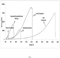
- FIG. 5 To illustrate the improvement of elastic energy achieved by the carbon composites, the stress-strain curves for the following samples are shown in FIG. 5 : (A) natural graphite, (B) expanded graphite, (C) a mixture of expanded graphite and a micro- or nano-sized binder formed at room temperature and atmospheric pressure, (D) a mixture of expanded graphite and a micro- or nano-sized binder formed by at a high temperature and atmospheric pressure; and (E) a carbon composite formed from expanded graphite and a micro- and nano-sized binder under high pressure and high temperature conditions.
- the natural graphite the sample was made by compressing natural graphite in a steel die at a high pressure.
- the expanded graphite sample was also made in a similar manner.
- the natural graphite has a very low elastic energy (area under the stress-strain curve) and is very brittle.
- the elastic energy of expanded graphite and the elastic energy of the mixture of expanded graphite and a micro- or nano-sized binder compacted at room temperature and high pressure is higher than that of the natural graphite.
- both the hard and soft carbon composites of the disclosure exhibit significantly improved elasticity shown by the notable increase of the elastic energy as compared to the natural graphite alone, the expanded graphite alone, and the mixture of expanded graphite and binder compacted at room temperature and high pressure.
- the carbon composites have an elastic elongation of greater than about 4%, greater than about 6%, or between about 4% and about 40%.
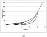
- FIG. 6 shows loop test results of a carbon composite at different loadings.
- FIG. 7 shows hysteresis results of a carbon composite tested at room temperature and 500°F (i.e. 260 °C) respectively. As shown in FIG. 7 , the elasticity of the carbon composite is maintained at 500°F (i.e. 260 °C).
- FIG. 8 compares a carbon composite before and after exposing to air at 500°C for 5 days.
- FIG. 9 (A) is a photo of a carbon composite sample after a thermo shock for 8 hours. The condition for the thermal shock is shown in FIG. 9(B) . As shown in Figs 8 and 9(A) , there are no changes to the carbon composite sample after exposing to air at 500°C for 25 hours or after the thermal shock.
- the carbon composites can have high thermal resistance with a range of operation temperatures from about -65°F up to about 1 200°F (i.e. -53 °C to 648 °C ) specifically up to about 1100°F (i.e. 593 °C) and more specifically about 1000°F (i.e. 537°C)
- the carbon composites can also have excellent chemical resistance at elevated temperatures.
- the composite is chemically resistant to water, oil, brines, and acids with resistance rating from good to excellent.
- the carbon composites can be used continuously at high temperatures and high pressures, for example, about 68°F to about 1200°F, or about 68°F to about 1000°F, or about 68°F to about 750°F (i.e. 20°C to 648°C, or 20°C to 537°C or 20°C to 398°C ) under wet conditions, including basic and acidic conditions.
- the carbon composites resist swelling and degradation of properties when exposed to chemical agents (e.g., water, brine, hydrocarbons, acids such as HCl, solvents such as toluene, etc.), even at elevated temperatures of up to 200°F, and at elevated pressures (greater than atmospheric pressure) for prolonged periods.
- chemical agents e.g., water, brine, hydrocarbons, acids such as HCl, solvents such as toluene, etc.
- FIG. 10 compares a carbon composite sample before and after exposing to tap water for 20 hours at 200°F, or after exposing to tap water for 3 days at 200°F. As shown in FIG. 10 , there are no changes to the sample.
- FIG. 10 compares a carbon composite sample before and after exposing to tap water for 20 hours at 200°F, or after exposing to tap water for 3 days at 200°F. As shown in FIG. 10 , there are no changes to the sample.
- the carbon composites are medium hard to extra hard with harness from about 50 in SHORE A up to about 75 in SHORE D scale.
- the carbon composites have stable sealing force at high temperatures.
- the stress decay of components under constant compressive strain is known as compression stress relaxation.
- a compression stress relaxation test also known as sealing force relaxation test measures the sealing force exerted by a seal or O-ring under compression between two plates. It provides definitive information for the prediction of the service life of materials by measuring the sealing force decay of a sample as a function of time, temperature and environment.
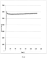
- FIG. 12 shows the sealing force relaxation test results of a carbon composite sample 600°F (i.e. 315°C).
- the sealing force of the carbon composite is stable at high temperatures.
- the sealing force of a sample of the composite at 15% strain and 600°F (i.e. 315°C) is maintained at about 5800 psi (i.e. 40 MPa) without relaxation for at least 20 minutes.
- an article comprises the carbon composites.
- the carbon composites may be used to form all or a portion of a downhole article in accordance with an aspect of an exemplary embodiment, as will be discussed more fully below.
- the carbon composites may be employed in a wide range of applications and environments.
- Subsurface extraction system 200 includes an uphole system 204 operatively connected to a downhole system 206.
- Uphole system 204 may include pumps 208 that aid in completion and/or extraction processes as well as a fluid storage portion 210.
- Fluid storage portion 210 may contain a fluid that may be introduced into downhole system 206.
- Downhole system 206 may include a downhole string 220 that extends into a wellbore 221 formed in formation 222.
- Wellbore 221 may include a wellbore casing 223.
- Downhole string 220 may include a number of connected downhole tubulars 224.
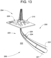
- One of tubulars 224 may support a flexible carbon composite annular seal 228.
- Flexible carbon composite annular seal 228 includes a chevron or V-shaped cross-section and may be made according to a method 280 depicted in FIG. 14 .
- a carbon composite mixture 302 ( FIG. 15 ) may be formed by combining/blending expanded graphite with metal binders. Metal binders may be present at a weight ratio of 50% or greater.
- the carbon composite mixture may be milled to form a powder, as indicated in block 304. However, it should be understood that the carbon composite mixture may also be utilized without milling.
- carbon composite mixture 302 is introduced into a mold 320 having a mold pin 322, shown in FIG. 15 .
- Mold pin 322 includes a surface profile (not separately labeled) that corresponds to a portion of the V-shaped cross-section of flexible carbon composite annular seal 228.
- FIG. 16 depicts a second mold pin 330 introduced into mold 320.
- Second mold pin 330 includes a surface profile (not separately labeled) that corresponds to another portion of the V-shaped cross-section of flexible carbon composite annular seal 228.
- Second mold pin 330 is urged toward first mold pin 322 to compress carbon composite mixture 302, as indicated in block 334.
- carbon composite mixture 302 may be heated to a selected temperature by introducing an electric current into first and second electrodes 342 and 344, as indicated in block 350. Heating may be achieved bypassing an electrical current through carbon composite mixture 302. Of course, it should be understood that carbon composite mixture 302 may be heated through other mechanisms. Also, it should be understood that the selected temperature may vary depending on desired characteristics of flexible carbon composite annular seal 228.
- flexible carbon composite annular seal 228 is removed from mold 320, as shown in FIG. 18 .
- flexible carbon composite annular seal 228 may be mounted to downhole tubular 224.
- flexible carbon composite seal 228 may be employed in a wide range of applications both downhole and uphole.
- flexible carbon composite seal 228 may be employed in resource exploration, resource extraction, and CO 2 sequestration systems.
- flexible carbon composite annular seal 228 may take on a variety of shapes.
- flexible carbon composite annular seal 228 may be machined to form a selected shape, as shown in block 365. In accordance with another exemplary aspect, as shown in FIG.
- a flexible carbon composite seal 362 is shown to have a C-shaped cross-section.
- a biasing element 364, shown in the form of a coil spring 366, may be integrated into flexible carbon composite annular seal 362, as shown in block 370.
- FIG. 20 depicts a flexible carbon composite annular seal 380 that includes first and second biasing members 390 and 400. First and second biasing members 390 and 400 are over molded or encapsulated by carbon composite mixture 302.
- Method 280 may also be employed to form other annular seal shapes such as a flexible carbon composite annular seal 410 having a generally circular cross-section shown in FIG. 21 , a flexible carbon composite annular seal 420 having a generally rectangular cross-section shown in FIG. 22 , a flexible carbon composite annular seal 430 having a generally T-shaped cross-section shown in FIG. 23 , and a flexible carbon composite annular seal 440 having a generally X-shaped cross-section shown in FIG. 24 .
- Other shapes are also contemplated.
- the use of the carbon composite mixture results in seal having a low coefficient of friction.
- the low coefficient of friction provides a self-lubricating quality to flexible carbon composite annular seal formed in accordance with exemplary embodiments.
- the flexible carbon composite of the exemplary embodiment includes a lower coefficient of friction that that of perfluoro-elastomers (FFKM), tetraflouroethylene/propylene (FEPM), nitrile rubber (NBR) and polyether-ether ketone (PEEK).
- FFKM perfluoro-elastomers
- FEPM tetraflouroethylene/propylene
- NBR nitrile rubber
- PEEK polyether-ether ketone
- the use of the carbon composite material as described above enables the flexible seal to be employed in a wide range of operating environments.
- the flexible seal resists galling, harsh chemicals, corrosion, oxidation and exposure to high temperatures. More specifically, the flexible seal may be employed in environments that reach upwards of 1200 °F (648.8 °C). Further, mechanical properties of the flexible seal including creating an interlocked structure by driving metal melt into gaps between graphite layered basal planes, may be tuned to application specific qualities by adjusting metal phase selection, graphite/metal ratio, heat treatment processing and the like. Also, it should be understood that in addition to hydrocarbon exploration and recovery applications, the flexible seal may also be employed in food and pharmaceutical applications.
Description
- Seals are widely used in resource exploration, extraction, and CO2 sequestration systems. Seals are employed both uphole and downhole. Dynamic seals provide a sealing interface between moving components and stationary components. Typically, seals are formed from plastics and elastomers. The use of plastics and elastomers both uphole and downhole present various challenges. Plastics and elastomers are prone to wear caused by high temperature, high pressure and corrosive environments such as found in hydrocarbon recovery. Accordingly, seals formed from plastics and elastomers may experience a limited service life or are restricted from certain operating environments. For example, many elastomers begin to decompose at temperatures approaching 600 °F (315.5 °C).
- Graphite is an allotrope of carbon and has a layered, planar structure. In each layer, the carbon atoms are arranged in hexagonal arrays or networks through covalent bonds. Different carbon layers however are held together only by weak van der Waals forces.
- Graphite has been used in a variety of applications including electronics, atomic energy, hot metal processing, coatings, aerospace, and the like due to its excellent thermal and electrical conductivities, lightness, low friction, and high heat and corrosion resistances. However, conventional graphite is not elastic and has low strength, which may limit its further applications such as forming seals employed in a downhole environment. The industry would be receptive to improvements in seal technology including seals formed from a material exhibiting enhanced flexibility, chemical stability, corrosive resistance, as well as high temperature and high pressure resistance properties.
-
US 4,269,391 discloses a valve sealing device comprising an expanded graphite compact part, which contacts the body of the valve, and another part which contacts the valve member and is made of a metallic material or a carbonaceous composite material.US 2,462,067 discloses flexible fluid-tight seals andUS 2004/026085 discloses a cyclic check valve. - The present invention provides a method of forming a flexible carbon composite self-lubricating seal as claimed in claim 1.
- Referring now to the drawings wherein like elements are numbered alike in the several Figures:
-
FIG. 1 is a scanning electron microscopic ("SEM") image of a composition containing expanded graphite and a micro- or nano-sized binder blended at room temperature and atmospheric pressure; -
FIG. 2 is a SEM image of a carbon composite formed from expanded graphite and a micro- or nano-sized binder under high pressure and high temperature conditions according to one embodiment of the disclosure; -
FIG. 3 is a SEM image of carbon microstructures according to another embodiment of the disclosure; -
FIG. 4 is a schematic illustration of a carbon composite according to an embodiment of the disclosure; -
FIG. 5 shows stress-strain curves of (A) natural graphite; (B) expanded graphite; (C) a mixture of expanded graphite and a micro- or nano-sized binder, where the sample is compacted at room temperature and high pressure; (D) a carbon composite according to one embodiment of the disclosure compacted from a mixture of expanded graphite and a micro- or nano-sized binder at a high temperature and a low pressure (also referred to as "soft composite"); and (E) a carbon composite according to another embodiment of the disclosure formed from expanded graphite and a micro- and nano-sized binder under high pressure and high temperature conditions (also referred to as "hard composite"); -
FIG. 6 shows loop test results of a carbon composite at different loadings; -
FIG. 7 shows hysteresis results of a carbon composite tested at room temperature and 500°F (i.e. 260 °C) respectively; -
FIG. 8 compares a carbon composite before and after exposing to air at 500°C for 25 hours; -
FIG. 9 (A) is a photo of a carbon composite after a thermal shock;FIG. 9 (B) illustrates the condition for the thermal shock; -
FIG. 10 compares a carbon composite sample (A) before and (B) after exposing to tap water for 20 hours at 200°F, (i.e. 93 °C) or (C) after exposing to tap water for 3 days at 200°F; (i.e. 93 °C) -
FIG. 11 compares a carbon composite sample (A) before and (B) after exposing to 15% HCl solution with inhibitor at 200°F (i.e. 93 °C) for 20 hours, or (C) after exposing to 15% HCl solution at 200°F (i.e. 93 °C) for 3 days; -
FIG. 12 shows the sealing force relaxation test results of a carbon composite at 600°F; (i.e. 315 °C) -
FIG. 13 depicts a subsurface exploration system including a tubular supporting a self-energizing flexible self-lubricating carbon composite seal, in accordance with an exemplary embodiment; -
FIG. 14 depicts a flow diagram illustrating a method of forming a flexible carbon composite self-lubricating annular seal; -
FIG. 15 depicts a carbon composite mixture introduced into a mold; -
FIG. 16 depicts the carbon composite mixture being compressed in the mold; -
FIG. 17 depicts the carbon composite mixture compressed in the mold being heated; -
FIG. 18 depicts a flexible carbon composite annular seal removed from the mold; -
FIG. 19 depicts a flexible carbon composite annular seal having an integrated biasing member, in accordance with an aspect of an exemplary embodiment; -
FIG. 20 depicts a flexible carbon composite annular seal formed around multiple biasing members, in accordance with another aspect of an exemplary embodiment; -
FIG. 21 depicts a flexible carbon composite annular seal having a generally circular cross-section, in accordance with yet another aspect of an exemplary embodiment; -
FIG. 22 depicts a flexible carbon composite annular seal having a generally rectangular cross-section, in accordance with still yet another aspect of an exemplary embodiment; -
FIG. 23 depicts a flexible carbon composite annular seal having a circular cross-section, in accordance with yet another aspect of an exemplary embodiment; -
FIG. 24 depicts a flexible carbon composite annular seal having a X-shaped cross-section, in accordance with yet still another aspect of an exemplary embodiment; and -
FIG. 25 depicts a graph comparing the flexible carbon composite, in accordance with an exemplary embodiment with other materials. - The inventors hereof have found that carbon composites formed from graphite and micro- or nano-sized binders at high temperatures have improved balanced properties as compared to graphite alone, a composition formed from the same graphite but different binders, or a mixture of the same graphite and the same binder blended at room temperature under atmospheric pressure or high pressures. The new carbon composites have excellent elasticity. In addition, the carbon composites have excellent mechanical strength, heat resistance, and chemical resistance at high temperatures. In a further advantageous feature, the composites keep various superior properties of the graphite such as heat conductivity, electrical conductivity, lubricity, and the alike.
- Without wishing to be bound by theory, it is believed that the improvement in mechanical strength is provided by a binding phase disposed between carbon microstructures. There are either no forces or only weak Van der Waals forces exist between the carbon microstructures thus the graphite bulk materials have weak mechanical strength. At high temperatures, the micro- and nano-sized binder liquefies and is dispersed evenly among carbon microstructures. Upon cooling, the binder solidifies and forms a binding phase binding the carbon nanostructures together through mechanical interlocking.
- Further without wishing to be bound by theory, for the composites having both improved mechanical strength and improved elasticity, it is believed that the carbon microstructures themselves are laminar structures having spaces between the stacked layers. The binder only selectively locks the microstructures at their boundaries without penetrating the microstructures. Thus the unbounded layers within the microstructures provide elasticity and the binding phase disposed between the carbon microstructures provides mechanical strength.
- The carbon microstructures are microscopic structures of graphite formed after compressing graphite into highly condensed state. They comprise graphite basal planes stacked together along the compression direction. As used herein, carbon basal planes refer to substantially flat, parallel sheets or layers of carbon atoms, where each sheet or layer has a single atom thickness. The graphite basal planes are also referred to as carbon layers. The carbon microstructures are generally flat and thin. They can have different shapes and can also be referred to as micro-flakes, micro-discs and the like. In an embodiment, the carbon microstructures are substantially parallel to each other.
- There are two types of voids in the carbon composites - voids or interstitial spaces between carbon microstructures and voids within each individual carbon microstructures. The interstitial spaces between the carbon microstructures have a size of about 0.1 to about 100 microns, specifically about 1 to about 20 microns whereas the voids within the carbon microstructures are much smaller and are generally between about 20 nanometers to about 1 micron, specifically about 200 nanometers to about 1 micron. The shape of the voids or interstitial spaces is not particularly limited. As used herein, the size of the voids or interstitial spaces refers to the largest dimension of the voids or interstitial spaces and can be determined by high resolution electron or atomic force microscope technology.
- The interstitial spaces between the carbon microstructures are filled with a micro- or nano-sized binder. For example, a binder can occupy about 10 % to about 90 % of the interstitial spaces between the carbon microstructures. However, the binder does not penetrate the individual carbon microstructures and the voids within carbon microstructures are unfilled, i.e., not filled with any binder. Thus the carbon layers within the carbon microstructures are not locked together by a binder. Through this mechanism, the flexibility of the carbon composite, particularly, expanded carbon composite can be preserved.
- The carbon microstructures have a thickness of about 1 to about 200 microns, about 1 to about 150 microns, about 1 to about 100 microns, about 1 to about 50 microns, or about 10 to about 20 microns. The diameter or largest dimension of the carbon microstructures is about 5 to about 500 microns or about 10 to about 500 microns. The aspect ratio of the carbon microstructures can be about 10 to about 500, about 20 to about 400, or about 25 to about 350. In an embodiment, the distance between the carbon layers in the carbon microstructures is about 0.3 nanometers to about 1 micron. The carbon microstructures can have a density of about 0.5 to about 3 g/cm3, or about 0.1 to about 2 g/cm3.
- As used herein, graphite includes natural graphite, synthetic graphite, expandable graphite, expanded graphite, or a combination comprising at least one of the foregoing. Natural graphite is graphite formed by Nature. It can be classified as "flake" graphite, "vein" graphite, and "amorphous" graphite. Synthetic graphite is a manufactured product made from carbon materials. Pyrolytic graphite is one form of the synthetic graphite. Expandable graphite refers to graphite having intercallant materials inserted between layers of natural graphite or synthetic graphite. A wide variety of chemicals have been used to intercalate graphite materials. These include acids, oxidants, halides, or the like. Exemplary intercallant materials include sulfuric acid, nitric acid, chromic acid, boric acid, SO3, or halides such as FeCl3, ZnCl2, and SbCls. Upon heating, the intercallant is converted from a liquid or solid state to a gas phase. Gas formation generates pressure which pushes adjacent carbon layers apart resulting in expanded graphite. The expanded graphite particles are vermiform in appearance, and are therefore commonly referred to as worms.
- According to the invention , the carbon composites comprise expanded graphite microstructures. Compared with other forms of the graphite, expanded graphite has high flexibility and compression recovery, and larger anisotropy. The composites formed from expanded graphite and micro- or nano-sized binder under high pressure and high temperature conditions can thus have excellent elasticity in addition to desirable mechanical strength.
- In the carbon composites, the carbon microstructures are held together by a binding phase. The binding phase comprises a binder which binds carbon microstructures by mechanical interlocking. Optionally, an interface layer is formed between the binder and the carbon microstructures. The interface layer can comprise chemical bonds, solid solutions, or a combination thereof. When present, the chemical bonds, solid solutions, or a combination thereof may strengthen the interlocking of the carbon microstructures. It is appreciated that the carbon microstructures may be held together by both mechanical interlocking and chemical bonding. For example the chemical bonding, solid solution, or a combination thereof may be formed between some carbon microstructures and the binder or for a particular carbon microstructure only between a portion of the carbon on the surface of the carbon microstructure and the binder. For the carbon microstructures or portions of the carbon microstructures that do not form a chemical bond, solid solution, or a combination thereof, the carbon microstructures can be bounded by mechanical interlocking. The thickness of the binding phase is about 0.1 to about 100 microns or about 1 to about 20 microns. The binding phase can form a continuous or discontinuous network that binds carbon microstructures together.
- The binder is a metal, an alloy, or a combination comprising at least one of the foregoing. The metal can be aluminum, copper, titanium, nickel, tungsten, chromium, iron, manganese, zirconium, hafnium, vanadium, niobium, molybdenum, tin, bismuth, antimony, lead, cadmium, and selenium. The alloy includes the alloys of aluminum, copper, titanium, nickel, tungsten, chromium, iron, manganese, zirconium, hafnium, vanadium, niobium, molybdenum, tin, bismuth, antimony, lead, cadmium, and selenium. In an embodiment, the binder comprises copper, nickel, chromium, iron, titanium, an alloy of copper, an alloy of nickel, an alloy of chromium, an alloy of iron, an alloy of titanium, or a combination comprising at least one of the foregoing metal or metal alloy. Exemplary alloys include steel, nickel-chromium based alloys such as Inconel*, and nickel-copper based alloys such as Monel alloys. Nickel-chromium based alloys can contain about 40-75% of Ni, about 10-35% of Cr. The nickel-chromium based alloys can also contain about 1 to about 15% of iron. Small amounts of Mo, Nb, Co, Mn, Cu, Al, Ti, Si, C, S, P, B, or a combination comprising at least one of the foregoing can also be included in the nickel-chromium based alloys. Nickel-copper based alloys are primarily composed of nickel (up to about 67%) and copper. The nickel-copper based alloys can also contain small amounts of iron, manganese, carbon, and silicon. These materials can be in different shapes, such as particles, fibers, and wires. Combinations of the materials can be used.
- The binder used to make the carbon composite is micro- or nano-sized. In an embodiment, the binder has an average particle size of about 0.05 to about 10 microns, specifically, about 0.5 to about 5 microns, more specifically about 0.1 to about 3 microns. Without wishing to be bound by theory, it is believed that when the binder has a size within these ranges, it disperses uniformly among the carbon microstructures.
- When an interface layer is present, the binding phase comprises a binder layer comprising a binder and an interface layer bonding one of the at least two carbon microstructures to the binder layer. In an embodiment, the binding phase comprises a binder layer, a first interface layer bonding one of the carbon microstructures to the binder layer, and a second interface layer bonding the other of the microstructures to the binder layer. The first interface layer and the second interface layer can have the same or different compositions.
- The interface layer comprises a C-metal bond, a C-B bond, a C-Si bond, a CO-Si bond, a C-O-metal bond, a metal carbon solution, or a combination comprising at least one of the foregoing. The bonds are formed from the carbon on the surface of the carbon microstructures and the binder.
- In an embodiment, the interface layer comprises carbides of the binder. The carbides include carbides of aluminum, titanium, nickel, tungsten, chromium, iron, manganese, zirconium, hafnium, vanadium, niobium, molybdenum, or a combination comprising at least one of the foregoing. These carbides are formed by reacting the corresponding metal or metal alloy binder with the carbon atoms of the carbon microstructures. The binding phase can also comprise SiC formed by reacting SiO2 or Si with the carbon of carbon microstructures, or B4C formed by reacting B or B2O3 with the carbon of the carbon microstructures. When a combination of binder materials is used, the interface layer can comprise a combination of these carbides. The carbides can be salt-like carbides such as aluminum carbide, covalent carbides such as SiC, B4C, interstitial carbides such as carbides of the
group - In another embodiment, the interface layer comprises a solid solution of carbon and the binder. Carbon have solubility in certain metal matrix or at certain temperature range, which helps both wetting and binding of metal phase onto carbon microstructures. Through heat-treatment, high solubility of carbon in metal can be maintained at low temperature. These metals include Co, Fe, La, Mn, Ni, or Cu. The binder layer can also comprises a combination of solid solutions and carbides.
- The carbon composites comprise about 20 to about 95 wt. %, about 20 to about 80 wt. %, or about 50 to about 80 wt. % of expanded graphite microstructures, based on the total weight of the composites. The binder is present in an amount of about 5 wt. % to about 75 wt. % or about 20 wt. % to about 50 wt. %, based on the total weight of the composites. In the carbon composites, the weight ratio of carbon relative to the binding is about 1:4 to about 20:1, or about 1:4 to about 4:1, or about 1:1 to about 4:1.
-
FIG. 1 is a SEM image of a composition containing expanded graphite and a micro- or nano-sized binder blended at room temperature and atmospheric pressure. As shown inFIG. 1 , the binder (white area) is only deposited on the surface of some of the expanded graphite worms. -
FIG. 2 is a SEM image of a carbon composite formed from expanded graphite and a micro- or nano-sized binder under high pressure and high temperature conditions. As shown inFIG. 2 , a binding phase (light area) is evenly distributed between the expanded graphite microstructures (dark area). - A SEM image of carbon graphite microstructures are shown in
FIG. 3 . An embodiment of a carbon composite is illustrated inFig 4 . As shown inFIG. 4 , the composite comprises carbon microstructures 1 andbinding phase 2 locking the carbon microstructures. Thebinding phase 2 comprisesbinder layer 3 and anoptional interface layer 4 disposed between the binder layer and the carbon microstructures. The carbon composite containsinterstitial space 5 among carbon microstructures 1. Within carbon microstructures, there areunfilled voids 6. - The carbon composites can optionally comprise a filler. Exemplary filler includes carbon fibers, carbon black, mica, clay, glass fiber, ceramic fibers, and ceramic hollow structures. Ceramic materials include SiC, Si3N4, SiO2, BN, and the like. The filler can be present in an amount of about 0.5 to about 10 wt. % or about 1 to about 8%.
- The composites can have any desired shape including a bar, block, sheet, tubular, cylindrical billet, toroid, powder, pellets, or other form that may be machined, formed or otherwise used to form useful articles of manufacture. The sizes or the dimension of these forms are not particularly limited. Illustratively, the sheet has a thickness of about 10 µm to about 10 cm and a width of about 10 mm to about 2 m. The powder comprises particles having an average size of about 10 µm to about 1 cm. The pellets comprise particles having an average size of about 1 cm to about 5 cm.
- One way to form the carbon composites is to compress a combination comprising carbon and a micro- or nano-sized binder to provide a green compact by cold pressing; and to compressing and heating the green compact thereby forming the carbon composites. In another embodiment, the combination can be pressed at room temperature to form a compact, and then the compact is heated at atmospheric pressure to form the carbon composite. These processes can be referred to as two-step processes. Alternatively, a combination comprising carbon and a micro- or nano-sized binder can be compressed and heated directly to form the carbon composites. The process can be referred to as a one-step process.
- The expanded graphite is present in an amount of about 20 wt.% to about 95 wt.%, about 20 wt.% to about 80 wt.%, or about 50 wt.% to about 80 wt.%, based on the total weight of the combination. The binder is present in an amount of about 5 wt. % to about 75 wt. % or about 20 wt. % to about 50 wt. %, based on the total weight of the combination. The graphite in the combination can be in the form of chip, powder, platelet, flake, or the like. In an embodiment, the graphite is in the form of flakes having a diameter of about 50 microns to about 5,000 microns, preferably about 100 to about 300 microns. The graphite flakes can have a thickness of about 1 to about 5 microns. The density of the combination is about 0.01 to about 0.05 g/cm3, about 0.01 to about 0.04 g/cm3, about 0.01 to about 0.03 g/cm3 or about 0.026 g/cm3. The combination can be formed by blending the graphite and the micro- or nano-sized binder via any suitable methods known in the art. Examples of suitable methods include ball mixing, acoustic mixing, ribbon blending, vertical screw mixing, and V-blending.
- Referring to the two-step process, cold pressing means that the combination comprising the graphite and the micro-sized or nano-sized binder is compressed at room temperature or at an elevated temperature as long as the binder does not significantly bond with the graphite microstructures. In an embodiment, greater than about 80 wt.%, greater than about 85 wt.%, greater than about 90 wt.%, greater than about 95 wt.%, or greater than about 99 wt.% of the microstructures are not bonded in the green compact. The pressure to form the green compact can be about 500 psi to about 10 ksi and the temperature can be about 20°C to about 200°C. The reduction ratio at this stage, i.e., the volume of the green compact relative to the volume of the combination, is about 40% to about 80%. The density of the green compact is about 0.1 to about 5 g/cm3, about 0.5 to about 3 g/cm3, or about 0.5 to about 2 g/cm3.
- The green compact can be heated at a temperature of about 350°C to about 1200°C, specifically about 800°C to about 1200°C to form the carbon composites. In an embodiment, the temperature is above the melting point of the binder, for example, about 20°C to about 100°C higher or about 20°C to about 50°C higher than the melting point of the binder. When the temperature is higher, the binder becomes less viscose and flows better, and less pressure may be required in order for the binder to be evenly distributed in the voids between the carbon microstructures. However, if the temperature is too high, it may have detrimental effects to the instrument.
- The temperature can be applied according to a predetermined temperature schedule or ramp rate. The means of heating is not particularly limited. Exemplary heating methods include direct current (DC) heating, induction heating, microwave heating, and spark plasma sintering (SPS). In an embodiment, the heating is conducted via DC heating. For example, the combination comprising the graphite and the micro- or nano-sized binder can be charged with a current, which flows through the combination generating heat very quickly. Optionally, the heating can also be conducted under an inert atmosphere, for example, under argon or nitrogen. In an embodiment, the green compact is heated in the presence of air.
- The heating can be conducted at a pressure of about 500 psi to about 30,000 psi or about 1000 psi to about 5000 psi (3,4 MPa to 206,8 MPa or 6,9 MPa to 34,4 MPa). The pressure can be a superatmospheric pressure or a subatmospheric pressure. Without wishing to be bound by theory, it is believed that when a superatmospheric pressure is applied to the combination, the micro- or nano-sized binder is forced into the voids between carbon microstructures through infiltration. When a subatmospheric pressure is applied to the combination, the micro- or nano-sized binder can also be forced into the voids between the carbon microstructures by capillary forces.
- In an embodiment, the desirable pressure to form the carbon composites is not applied all at once. After the green compact is loaded, a low pressure is initially applied to the composition at room temperature or at a low temperature to close the large pores in the composition. Otherwise, the melted binder may flow to the surface of the die. Once the temperature reaches the predetermined maximum temperature, the desirable pressure required to make the carbon composites can be applied. The temperature and the pressure can be held at the predetermined maximum temperature and the predetermined maximum temperature for 5 minutes to 120 minutes.
- The reduction ratio at this stage, i.e. the volume of the carbon composite relative to the volume of the green compact, is about 10% to about 70% or about 20 to about 40%. The density of the carbon composite can be varied by controlling the degree of compression. The carbon composites have a density of about 0.5 to about 10 g/cm3, about 1 to about 8 g/cm3, about 1 to about 6 g/cm3, about 2 to about 5 g/cm3, about 3 to about 5 g/cm3, or about 2 to about 4 g/cm3.
- Alternatively, also referring to a two-step process, the combination can be first pressed at room temperature and a pressure of about 500 psi to 30,000 psi (3,4 MPa to 206,8 MPa) to form a compact; the compact can be further heated at a temperature higher than the melting point of the binder to make the carbon composite. In an embodiment, the temperature can be about 20°C to about 100°C higher or about 20°C to about 50°C higher than the melting point of the binder. The heating can be conducted at atmospheric pressure.
- In another embodiment, the carbon composite can be made from the combination of the graphite and the binder directly without making the green compact. The pressing and the heating can be carried out simultaneously. Suitable pressures and temperatures can be the same as discussed herein for the second step of the two-step process.
- Hot pressing is a process that applies temperature and pressure simultaneously. It can be used in both the one-step and the two-step processes to make carbon composites.
- The carbon composites can be made in a mold through a one-step or a two-step process. The obtained carbon composites can be further machined or shaped to form a bar, block, tubular, cylindrical billet, or toroid. Machining includes cutting, sawing, ablating, milling, facing, lathing, boring, and the like using, for example, a miller, saw, lathe, router, electric discharge machine, and the like. Alternatively, the carbon composite can be directly molded to the useful shape by choosing the molds having the desired shape.
- Sheet materials such as web, paper, strip, tape, foil, mat or the like can also be made via hot rolling. In an embodiment, the carbon composite sheets made by hot rolling can be further heated to allow the binder to effectively bond the carbon microstructures together.
- Carbon composite pellets can be made by extrusion. For example, a combination of the graphite and the micro- or nano-sized binder can be first loaded in a container. Then combination is pushed into an extruder through a piston. The extrusion temperature can be about 350°C to about 1400°C or about 800°C to about 1200°C. In an embodiment, the extrusion temperature is higher than the melting point of the binder, for example, about 20 to about 50°C higher than the melting point of the binder. In an embodiment, wires are obtained from the extrusion, which can be cut to form pellets. In another embodiment, pellets are directly obtained from the extruder. Optionally, a post treatment process can be applied to the pellets. For example, the pellets can be heated in a furnace above the melting temperature of the binder so that the binder can bond the carbon microstructures together if the carbon microstructures have not been bonded or not adequately bonded during the extrusion.
- Carbon composite powder can be made by milling carbon composites, for example a solid piece, through shearing forces (cutting forces). It is noted that the carbon composites should not be smashed. Otherwise, the voids within the carbon microstructures may be destroyed thus the carbon composites lose elasticity.
- The carbon composites have a number of advantageous properties for use in a wide variety of applications. In an especially advantageous feature, by forming carbon composites, both the mechanical strength and the elastomeric properties are improved.
- To illustrate the improvement of elastic energy achieved by the carbon composites, the stress-strain curves for the following samples are shown in
FIG. 5 : (A) natural graphite, (B) expanded graphite, (C) a mixture of expanded graphite and a micro- or nano-sized binder formed at room temperature and atmospheric pressure, (D) a mixture of expanded graphite and a micro- or nano-sized binder formed by at a high temperature and atmospheric pressure; and (E) a carbon composite formed from expanded graphite and a micro- and nano-sized binder under high pressure and high temperature conditions. For the natural graphite, the sample was made by compressing natural graphite in a steel die at a high pressure. The expanded graphite sample was also made in a similar manner. - As shown in
Fig. 5 , the natural graphite has a very low elastic energy (area under the stress-strain curve) and is very brittle. The elastic energy of expanded graphite and the elastic energy of the mixture of expanded graphite and a micro- or nano-sized binder compacted at room temperature and high pressure is higher than that of the natural graphite. Conversely, both the hard and soft carbon composites of the disclosure exhibit significantly improved elasticity shown by the notable increase of the elastic energy as compared to the natural graphite alone, the expanded graphite alone, and the mixture of expanded graphite and binder compacted at room temperature and high pressure. In an embodiment, the carbon composites have an elastic elongation of greater than about 4%, greater than about 6%, or between about 4% and about 40%. - The elasticity of the carbon composites is further illustrated in
Figs 6 and7 .FIG. 6 shows loop test results of a carbon composite at different loadings.FIG. 7 shows hysteresis results of a carbon composite tested at room temperature and 500°F (i.e. 260 °C) respectively. As shown inFIG. 7 , the elasticity of the carbon composite is maintained at 500°F (i.e. 260 °C). - In addition to mechanical strength and elasticity, the carbon composites can also have excellent thermal stability at high temperatures.
FIG. 8 compares a carbon composite before and after exposing to air at 500°C for 5 days.FIG. 9 (A) is a photo of a carbon composite sample after a thermo shock for 8 hours. The condition for the thermal shock is shown inFIG. 9(B) . As shown inFigs 8 and9(A) , there are no changes to the carbon composite sample after exposing to air at 500°C for 25 hours or after the thermal shock. The carbon composites can have high thermal resistance with a range of operation temperatures from about -65°F up to about 1 200°F (i.e. -53 °C to 648 °C ) specifically up to about 1100°F (i.e. 593 °C) and more specifically about 1000°F (i.e. 537°C) - The carbon composites can also have excellent chemical resistance at elevated temperatures. In an embodiment, the composite is chemically resistant to water, oil, brines, and acids with resistance rating from good to excellent. In an embodiment, the carbon composites can be used continuously at high temperatures and high pressures, for example, about 68°F to about 1200°F, or about 68°F to about 1000°F, or about 68°F to about 750°F (i.e. 20°C to 648°C, or 20°C to 537°C or 20°C to 398°C ) under wet conditions, including basic and acidic conditions. Thus, the carbon composites resist swelling and degradation of properties when exposed to chemical agents (e.g., water, brine, hydrocarbons, acids such as HCl, solvents such as toluene, etc.), even at elevated temperatures of up to 200°F, and at elevated pressures (greater than atmospheric pressure) for prolonged periods. The chemical resistance of the carbon composite is illustrated in
Figs 10 and 11. FIG. 10 compares a carbon composite sample before and after exposing to tap water for 20 hours at 200°F, or after exposing to tap water for 3 days at 200°F. As shown inFIG. 10 , there are no changes to the sample.FIG. 11 compares a carbon composite sample before and after exposing to 15% HCl solution with inhibitor at 200°F for 20 hours, or after exposing to 15% HCl solution at 200°F for 3 days. Again, there are no changes to the carbon composite sample. (200°F= 93°C) - The carbon composites are medium hard to extra hard with harness from about 50 in SHORE A up to about 75 in SHORE D scale.
- As a further advantageous feature, the carbon composites have stable sealing force at high temperatures. The stress decay of components under constant compressive strain is known as compression stress relaxation. A compression stress relaxation test also known as sealing force relaxation test measures the sealing force exerted by a seal or O-ring under compression between two plates. It provides definitive information for the prediction of the service life of materials by measuring the sealing force decay of a sample as a function of time, temperature and environment.
FIG. 12 shows the sealing force relaxation test results of acarbon composite sample 600°F (i.e. 315°C). As shown inFIG. 12 , the sealing force of the carbon composite is stable at high temperatures. In an embodiment, the sealing force of a sample of the composite at 15% strain and 600°F (i.e. 315°C) is maintained at about 5800 psi (i.e. 40 MPa) without relaxation for at least 20 minutes. - The carbon composites described above may be useful for preparing articles for a wide variety of applications including, but not limited to, electronics, this hot metal processing, coatings, aerospace, automotive, oil and gas, and marine applications. Exemplary articles include seals, bearings, bearing seats, packers, valves, engines, reactors, cooling systems, and heat sinks. Thus, in an embodiment, an article comprises the carbon composites. The carbon composites may be used to form all or a portion of a downhole article in accordance with an aspect of an exemplary embodiment, as will be discussed more fully below. Of course, it should be understood that the carbon composites may be employed in a wide range of applications and environments.
- A subsurface exploration system, in accordance with an exemplary embodiment, is indicated generally at 200, in
FIG. 13 .Subsurface extraction system 200 includes anuphole system 204 operatively connected to adownhole system 206.Uphole system 204 may includepumps 208 that aid in completion and/or extraction processes as well as afluid storage portion 210.Fluid storage portion 210 may contain a fluid that may be introduced intodownhole system 206.Downhole system 206 may include adownhole string 220 that extends into awellbore 221 formed information 222.Wellbore 221 may include awellbore casing 223.Downhole string 220 may include a number of connecteddownhole tubulars 224. One oftubulars 224 may support a flexible carbon compositeannular seal 228. - Flexible carbon composite
annular seal 228 includes a chevron or V-shaped cross-section and may be made according to amethod 280 depicted inFIG. 14 . In block 300 a carbon composite mixture 302 (FIG. 15 ) may be formed by combining/blending expanded graphite with metal binders. Metal binders may be present at a weight ratio of 50% or greater. In accordance with an aspect of an exemplary embodiment, the carbon composite mixture may be milled to form a powder, as indicated inblock 304. However, it should be understood that the carbon composite mixture may also be utilized without milling. - In
block 306, carboncomposite mixture 302 is introduced into amold 320 having amold pin 322, shown inFIG. 15 .Mold pin 322 includes a surface profile (not separately labeled) that corresponds to a portion of the V-shaped cross-section of flexible carbon compositeannular seal 228.FIG. 16 depicts asecond mold pin 330 introduced intomold 320.Second mold pin 330 includes a surface profile (not separately labeled) that corresponds to another portion of the V-shaped cross-section of flexible carbon compositeannular seal 228.Second mold pin 330 is urged towardfirst mold pin 322 to compress carboncomposite mixture 302, as indicated inblock 334. InFIG. 17 , carboncomposite mixture 302 may be heated to a selected temperature by introducing an electric current into first andsecond electrodes block 350. Heating may be achieved bypassing an electrical current through carboncomposite mixture 302. Of course, it should be understood that carboncomposite mixture 302 may be heated through other mechanisms. Also, it should be understood that the selected temperature may vary depending on desired characteristics of flexible carbon compositeannular seal 228. - In
block 360, flexible carbon compositeannular seal 228 is removed frommold 320, as shown inFIG. 18 . At this point, flexible carbon compositeannular seal 228 may be mounted todownhole tubular 224. Of course, it should be understood that flexible carboncomposite seal 228 may be employed in a wide range of applications both downhole and uphole. It should also be understood that flexible carboncomposite seal 228 may be employed in resource exploration, resource extraction, and CO2 sequestration systems. It should be further understood that flexible carbon compositeannular seal 228 may take on a variety of shapes. In accordance with an aspect of an exemplary embodiment, flexible carbon compositeannular seal 228 may be machined to form a selected shape, as shown inblock 365. In accordance with another exemplary aspect, as shown inFIG. 19 , a flexible carboncomposite seal 362 is shown to have a C-shaped cross-section. In such a case, a biasingelement 364, shown in the form of acoil spring 366, may be integrated into flexible carbon compositeannular seal 362, as shown inblock 370.FIG. 20 depicts a flexible carbon compositeannular seal 380 that includes first andsecond biasing members members composite mixture 302. -
Method 280 may also be employed to form other annular seal shapes such as a flexible carbon compositeannular seal 410 having a generally circular cross-section shown inFIG. 21 , a flexible carbon compositeannular seal 420 having a generally rectangular cross-section shown inFIG. 22 , a flexible carbon compositeannular seal 430 having a generally T-shaped cross-section shown inFIG. 23 , and a flexible carbon compositeannular seal 440 having a generally X-shaped cross-section shown inFIG. 24 . Other shapes are also contemplated. - The use of the carbon composite mixture results in seal having a low coefficient of friction. The low coefficient of friction provides a self-lubricating quality to flexible carbon composite annular seal formed in accordance with exemplary embodiments. As shown in
FIG. 24 , the flexible carbon composite of the exemplary embodiment includes a lower coefficient of friction that that of perfluoro-elastomers (FFKM), tetraflouroethylene/propylene (FEPM), nitrile rubber (NBR) and polyether-ether ketone (PEEK). In addition to self-lubricating characteristics due to the low coefficient of friction, the use of the carbon composite material as described above enables the flexible seal to be employed in a wide range of operating environments. The flexible seal resists galling, harsh chemicals, corrosion, oxidation and exposure to high temperatures. More specifically, the flexible seal may be employed in environments that reach upwards of 1200 °F (648.8 °C). Further, mechanical properties of the flexible seal including creating an interlocked structure by driving metal melt into gaps between graphite layered basal planes, may be tuned to application specific qualities by adjusting metal phase selection, graphite/metal ratio, heat treatment processing and the like. Also, it should be understood that in addition to hydrocarbon exploration and recovery applications, the flexible seal may also be employed in food and pharmaceutical applications.
Claims (15)
- A method (280) of forming a flexible carbon composite self-lubricating seal (228) comprising:compressing a carbon composite mixture (302) into a mold (320) forming a flexible carbon composite self-lubricating annular seal (228);wherein the carbon composite mixture comprises 20 to 95 wt%, based on the total weight of the composite, of expanded graphite microstructures and 5 to 75 wt.%, based on the total weight of the composite, of a nano-sized or micro-sized binder selected from a metal or a metal alloy.
- The method (280) of claim 1, further comprising: heating the carbon composite mixture (302) in the mold (320) to a selected temperature.
- The method (280) of claim 2, wherein heating the carbon composite mixture (302) includes passing an electrical current through the carbon composite mixture (302).
- The method (280) of claim 2, wherein heating the carbon composite mixture (302) includes melting metal binders in the carbon composite mixture (302) forming a metal melt.
- The method (280) of claim 4, further comprising: driving the metal melt into gaps between graphite basal planes in the carbon composite mixture (302) forming an interlocked structure.
- The method (280) of claim 2, wherein heating the carbon composite mixture (302) includes inductively heating the carbon composite mixture (302).
- The method (280) of claim 1, further comprising: forming the carbon composite mixture (302) includes mixing expanded graphite with metal binders.
- The method (280) of claim 6, wherein forming the carbon composite mixture (302) includes grinding the carbon composite mixture (302) into a powder.
- The method (280) of claim 1, further comprising: removing the flexible carbon composite self-lubricating annular seal (228) from the mold (320).
- The method (280) of claim 1, further comprising: integrating a biasing member (390,400) into the flexible carbon composite self-lubricating annular seal (228).
- The method (280) of claim 10, wherein integrating the biasing member (390,400) includes positioning a coil spring (366) in the flexible carbon composite self-lubricating annular seal (228).
- The method (280) of claim 10, wherein integrating the biasing member (390,400) includes encapsulating the biasing member (390,400) in the flexible carbon composite self-lubricating annular seal (228).
- The method (280) of claim 1, further comprising: mounting the flexible carbon composite self-lubricating annular seal (228) to a downhole tubular (224).
- The method (280) of claim 13, further comprising: inhibiting flow at the flexible carbon composite self-lubricating annular seal (228) on the downhole tubular (224).
- The method (280) of claim 1, further comprising: machining the flexible carbon composite self-lubricating annular seal (228) to establish a selected seal shape.
Applications Claiming Priority (2)
| Application Number | Priority Date | Filing Date | Title |
|---|---|---|---|
| US14/553,472 US10300627B2 (en) | 2014-11-25 | 2014-11-25 | Method of forming a flexible carbon composite self-lubricating seal |
| PCT/US2015/056886 WO2016085596A1 (en) | 2014-11-25 | 2015-10-22 | Method of forming a flexible carbon composite self-lubricating seal |
Publications (3)
| Publication Number | Publication Date |
|---|---|
| EP3224504A1 EP3224504A1 (en) | 2017-10-04 |
| EP3224504A4 EP3224504A4 (en) | 2018-08-01 |
| EP3224504B1 true EP3224504B1 (en) | 2023-08-16 |
Family
ID=56009689
Family Applications (1)
| Application Number | Title | Priority Date | Filing Date |
|---|---|---|---|
| EP15862719.0A Active EP3224504B1 (en) | 2014-11-25 | 2015-10-22 | Method of forming a flexible carbon composite self-lubricating seal |
Country Status (6)
| Country | Link |
|---|---|
| US (1) | US10300627B2 (en) |
| EP (1) | EP3224504B1 (en) |
| JP (1) | JP6736810B2 (en) |
| CN (2) | CN107073572A (en) |
| CA (1) | CA2968949C (en) |
| WO (1) | WO2016085596A1 (en) |
Families Citing this family (11)
| Publication number | Priority date | Publication date | Assignee | Title |
|---|---|---|---|---|
| US9963395B2 (en) | 2013-12-11 | 2018-05-08 | Baker Hughes, A Ge Company, Llc | Methods of making carbon composites |
| US9325012B1 (en) | 2014-09-17 | 2016-04-26 | Baker Hughes Incorporated | Carbon composites |
| US10315922B2 (en) | 2014-09-29 | 2019-06-11 | Baker Hughes, A Ge Company, Llc | Carbon composites and methods of manufacture |
| US10480288B2 (en) | 2014-10-15 | 2019-11-19 | Baker Hughes, A Ge Company, Llc | Articles containing carbon composites and methods of manufacture |
| US9962903B2 (en) | 2014-11-13 | 2018-05-08 | Baker Hughes, A Ge Company, Llc | Reinforced composites, methods of manufacture, and articles therefrom |
| US9745451B2 (en) | 2014-11-17 | 2017-08-29 | Baker Hughes Incorporated | Swellable compositions, articles formed therefrom, and methods of manufacture thereof |
| US11097511B2 (en) | 2014-11-18 | 2021-08-24 | Baker Hughes, A Ge Company, Llc | Methods of forming polymer coatings on metallic substrates |
| US10300627B2 (en) | 2014-11-25 | 2019-05-28 | Baker Hughes, A Ge Company, Llc | Method of forming a flexible carbon composite self-lubricating seal |
| US9840887B2 (en) | 2015-05-13 | 2017-12-12 | Baker Hughes Incorporated | Wear-resistant and self-lubricant bore receptacle packoff tool |
| US10125274B2 (en) | 2016-05-03 | 2018-11-13 | Baker Hughes, A Ge Company, Llc | Coatings containing carbon composite fillers and methods of manufacture |
| US10344559B2 (en) | 2016-05-26 | 2019-07-09 | Baker Hughes, A Ge Company, Llc | High temperature high pressure seal for downhole chemical injection applications |
Citations (2)
| Publication number | Priority date | Publication date | Assignee | Title |
|---|---|---|---|---|
| KR20080034366A (en) * | 2006-10-16 | 2008-04-21 | 요업기술원 | Graphite with high density and manufacturing method thereof |
| RU2510387C1 (en) * | 2012-11-22 | 2014-03-27 | Открытое акционерное общество "Авиационная корпорация "Рубин" (ОАО "АК "Рубин") | Method of producing frictional carbon-carbon composite material and material |
Family Cites Families (226)
| Publication number | Priority date | Publication date | Assignee | Title |
|---|---|---|---|---|
| US2462067A (en) | 1944-12-01 | 1949-02-22 | Timken Axle Co Detroit | Resilient lubricant seal |
| US3145778A (en) | 1961-11-02 | 1964-08-25 | Pan American Petroleum Corp | Well completion apparatus |
| US3246369A (en) * | 1964-03-09 | 1966-04-19 | Federal Mogul Corp | Mold for fluid seal |
| US3521853A (en) | 1966-12-12 | 1970-07-28 | Thomas S Gillis Jr | Throttle and shutoff valve |
| US3561770A (en) * | 1968-10-07 | 1971-02-09 | Federal Mogul Corp | Shaft seal |
| FR2065763A5 (en) * | 1969-08-27 | 1971-08-06 | Lorraine Carbone | |
| US3666852A (en) * | 1970-01-06 | 1972-05-30 | Federal Mogul Corp | Method for making an elastomeric annular seal with enclosed garter spring |
| US3807996A (en) | 1972-07-10 | 1974-04-30 | Union Carbide Corp | Carbon fiber reinforced nickel matrix composite having an intermediate layer of metal carbide |
| DE2244470C3 (en) | 1972-09-11 | 1975-03-13 | Deutsche Edelstahlwerke Ag, 4150 Krefeld | Highly corrosion-resistant and wear-resistant sintered steel alloy |
| US3904405A (en) | 1973-02-02 | 1975-09-09 | Ametek Inc | Sliding seal parts and process of making |
| JPS5614732B2 (en) | 1973-03-12 | 1981-04-06 | ||
| US3981427A (en) | 1975-04-28 | 1976-09-21 | Brookes Ronald R | Method of laminating graphite sheets to a metal substrate |
| JPS5313610A (en) | 1976-07-23 | 1978-02-07 | Nippon Carbon Co Ltd | Compound sheet materials |
| US4223075A (en) | 1977-01-21 | 1980-09-16 | The Aerospace Corporation | Graphite fiber, metal matrix composite |
| US4269391A (en) | 1977-04-28 | 1981-05-26 | Nippon Petrochemicals Co., Ltd. | Valve sealing device and a valve |
| US4116451A (en) | 1977-06-16 | 1978-09-26 | Maurer Engineering, Inc. | Shaft seal assembly and seal ring therefor |
| JPS54133256A (en) | 1977-12-08 | 1979-10-16 | Taiho Kogyo Co Ltd | Slider material for shaft sealing |
| JPS5524949A (en) | 1978-08-11 | 1980-02-22 | Hitachi Ltd | Manufacture of graphite-containing aluminium alloy |
| US4270569A (en) | 1978-10-16 | 1981-06-02 | Christensen Inc. | Valve assembly for the remote control of fluid flow having an automatic time delay |
| US4358506A (en) | 1980-06-09 | 1982-11-09 | Josef Intrater | Metal and carbon composites thereof |
| ATE15792T1 (en) | 1981-06-08 | 1985-10-15 | Advanced Tech Inc | ALLOYS BASED ON METAL, CARBIDE, CARBIDE AND OTHER COMPOSITIONS AND PROCESSES FOR THEIR PRODUCTION. |
| US4372393A (en) | 1981-06-16 | 1983-02-08 | Baker International Corporation | Casing bore receptacle |
| FR2512154B1 (en) * | 1981-09-03 | 1984-06-15 | Elf Aquitaine | |
| JPS59129142A (en) | 1983-01-14 | 1984-07-25 | 日本ピラ−工業株式会社 | Composite shape and its manufacture |
| US4567103A (en) | 1983-07-28 | 1986-01-28 | Union Carbide Corporation | Carbonaceous articles having oxidation prohibitive coatings thereon |
| DE3435043A1 (en) | 1984-09-24 | 1986-04-03 | C. Conradty Nürnberg GmbH & Co KG, 8505 Röthenbach | POLYGRANULAR CARBON BODY AND METHOD FOR THE PRODUCTION THEREOF |
| US4732364A (en) | 1984-12-17 | 1988-03-22 | Ameron Iron Works USA, Inc. | Wear resistant diamond cladding |
| DE3677302D1 (en) | 1985-08-27 | 1991-03-07 | Intercal Co | SEALING OBJECT FROM GRAPHITE STORAGE LINKS. |
| US4798771A (en) | 1985-08-27 | 1989-01-17 | Intercal Company | Bearings and other support members made of intercalated graphite |
| US4743033A (en) * | 1985-12-16 | 1988-05-10 | Baker Oil Tools, Inc. | Dynamic seal assembly for piston and cylinder operating in subterranean wells |
| JPS63135653A (en) | 1986-11-25 | 1988-06-08 | Nippon Pillar Packing Co Ltd | Packing material |
| GB2201679B (en) | 1987-02-24 | 1990-11-07 | Aisin Seiki | Filter materials |
| CN87207110U (en) | 1987-05-29 | 1988-01-20 | 吴树济 | Metal-expanded graphite complex spacer |
| US4780226A (en) | 1987-08-03 | 1988-10-25 | General Motors Corporation | Lubrication for hot working rare earth-transition metal alloys |
| US4789166A (en) * | 1987-09-14 | 1988-12-06 | Microdot Inc. | Rotary shaft wave seal |
| US5225379A (en) | 1988-02-09 | 1993-07-06 | Ucar Carbon Technology Corporation | Composites of flexible graphite particles and amorphous carbon |
| US4826181A (en) | 1988-02-09 | 1989-05-02 | Union Carbide Corporation | Seal utilizing composites of flexible graphite particles and amorphous carbon |
| US5646231A (en) | 1988-02-17 | 1997-07-08 | Maxdem, Incorporated | Rigid-rod polymers |
| US5228701A (en) | 1988-03-22 | 1993-07-20 | Ucar Carbon Technology Corporation | Flexible graphite articles with an amorphous carbon phase at the surface |
| US5392982A (en) | 1988-11-29 | 1995-02-28 | Li; Chou H. | Ceramic bonding method |
| US5163692A (en) * | 1989-07-24 | 1992-11-17 | Furon Company | One-piece composite lip seal |
| US5117913A (en) | 1990-09-27 | 1992-06-02 | Dresser Industries Inc. | Chemical injection system for downhole treating |
| GB2248255B (en) | 1990-09-27 | 1994-11-16 | Solinst Canada Ltd | Borehole packer |
| DE4117074A1 (en) | 1991-05-25 | 1992-11-26 | Bayer Ag | METHOD FOR PRODUCING MOLDED BODIES |
| JP2769523B2 (en) | 1994-01-31 | 1998-06-25 | 株式会社キッツ | Packing ring structure and manufacturing method thereof, and sealing device using the same |
| DE4133546C2 (en) | 1991-10-10 | 2000-12-07 | Mahle Gmbh | Piston-cylinder arrangement of an internal combustion engine |
| DE69219552T2 (en) | 1991-10-23 | 1997-12-18 | Inco Ltd | Nickel-coated carbon preform |
| US5283121A (en) | 1991-11-08 | 1994-02-01 | Bordner Barry A | Corrosion and abrasion resistant industrial roll coating with non-sticking properties |
| US5201532A (en) | 1991-12-12 | 1993-04-13 | Mark Controls Corporation | Flexible non-planar graphite sealing ring |
| US5240766A (en) | 1992-04-01 | 1993-08-31 | Hollingsworth & Vose Company | Gasket material |
| TW201341B (en) | 1992-08-07 | 1993-03-01 | Raychem Corp | Low thermal expansion seals |
| US5362074A (en) * | 1993-02-26 | 1994-11-08 | Dana Corporation | Reinforced core heavy duty gasket |
| JP3028171B2 (en) | 1993-08-31 | 2000-04-04 | 日本ピラー工業株式会社 | Composite gasket |
| US5499827A (en) * | 1993-06-30 | 1996-03-19 | Thermal Dynamics International, Inc. | Seal for shafts and valve stems |
| CN2171734Y (en) | 1993-10-16 | 1994-07-13 | 慈溪市城关氟塑厂 | Soft graphite strong sealed board |
| CN2177841Y (en) | 1993-11-30 | 1994-09-21 | 茹春浩 | Sealing packing |
| JP2645800B2 (en) | 1993-12-14 | 1997-08-25 | 日本ピラー工業株式会社 | Expanded graphite seal material, method for producing the same, and gasket sheet |
| US5545474A (en) | 1994-03-01 | 1996-08-13 | Martin Marietta Corporation | Electromagnetic-attenuating coating materials |
| GB2287734B (en) * | 1994-03-22 | 1997-10-01 | Fmc Corp | Seals containing non-metallic springs |
| US5495979A (en) | 1994-06-01 | 1996-03-05 | Surmet Corporation | Metal-bonded, carbon fiber-reinforced composites |
| US5509555A (en) | 1994-06-03 | 1996-04-23 | Massachusetts Institute Of Technology | Method for producing an article by pressureless reactive infiltration |
| US5494753A (en) | 1994-06-20 | 1996-02-27 | General Electric Company | Articles having thermal conductors of graphite |
| US5455000A (en) | 1994-07-01 | 1995-10-03 | Massachusetts Institute Of Technology | Method for preparation of a functionally gradient material |
| KR960023949A (en) * | 1994-12-28 | 1996-07-20 | 수우 에이 그리핀 | Flexible fluid seals |
| US5467814A (en) | 1995-02-24 | 1995-11-21 | The United States Of America As Represented By The Secretary Of The Navy | Graphite/epoxy heat sink/mounting for common pressure vessel |
| US5765838A (en) * | 1995-06-06 | 1998-06-16 | Nippon Pillar Packing Co., Ltd. | Sealing gasket made of expanded graphite, with opened thin-leaf surface structure |
| GB9600103D0 (en) | 1996-01-04 | 1996-03-06 | Nodeco Ltd | Improvements to offshore drilling apparatus |
| US5968653A (en) | 1996-01-11 | 1999-10-19 | The Morgan Crucible Company, Plc | Carbon-graphite/silicon carbide composite article |
| GB9604757D0 (en) | 1996-03-06 | 1996-05-08 | Flexitallic Sealing Materials | Seal material |
| US5730444A (en) | 1996-03-08 | 1998-03-24 | Skf Usa Inc. | Seal with embedded garter spring |
| US6182974B1 (en) | 1996-03-22 | 2001-02-06 | Garlock, Inc. | Stuffing box packing assembly |
| CN1074748C (en) | 1996-07-05 | 2001-11-14 | 日本皮拉工业株式会社 | Seal stock of inflated graphite and method of mfg. same |
| GB2317929B (en) | 1996-10-01 | 2000-11-22 | Flexitallic Sealing Materials | Sealing system |
| US5775429A (en) | 1997-02-03 | 1998-07-07 | Pes, Inc. | Downhole packer |
| JP3812035B2 (en) | 1997-02-10 | 2006-08-23 | オイレス工業株式会社 | Sphere-shaped sealing body and method for manufacturing the same |
| US6131651A (en) | 1998-09-16 | 2000-10-17 | Advanced Ceramics Corporation | Flexible heat transfer device and method |
| DE19804283B4 (en) | 1998-02-04 | 2006-10-12 | Sgl Carbon Ag | Metal reinforced graphite laminate |
| US6050572A (en) | 1998-03-09 | 2000-04-18 | Bal Seal Engineering Company, Inc. | Rotary cartridge seals with retainer |
| US5988202A (en) | 1998-11-02 | 1999-11-23 | Spitzer, Sr.; Harry L. | Pre-set maximum flow metering and mixing valves |
| US20010003389A1 (en) | 1999-02-16 | 2001-06-14 | C. James Bushman | High temperature static seal |
| US6128874A (en) | 1999-03-26 | 2000-10-10 | Unifrax Corporation | Fire resistant barrier for dynamic expansion joints |
| JP3987656B2 (en) | 1999-03-30 | 2007-10-10 | 財団法人鉄道総合技術研究所 | Titanium copper carbon composite material for sliding current collection and manufacturing method of titanium copper carbon composite material for sliding current collection |
| US6923631B2 (en) | 2000-04-12 | 2005-08-02 | Advanced Energy Technology Inc. | Apparatus for forming a resin impregnated flexible graphite sheet |
| US6075701A (en) | 1999-05-14 | 2000-06-13 | Hughes Electronics Corporation | Electronic structure having an embedded pyrolytic graphite heat sink material |
| US6506482B1 (en) | 1999-05-24 | 2003-01-14 | Carbon Ceramics Company, Llc | Vitreous carbon composite and method of making and using same |
| JP3547078B2 (en) | 1999-06-11 | 2004-07-28 | ニチアス株式会社 | Manufacturing method of cylinder block |
| US6234490B1 (en) | 1999-07-09 | 2001-05-22 | George B. Champlin | Leakfree pumpback packing |
| GB9923092D0 (en) | 1999-09-30 | 1999-12-01 | Solinst Canada Ltd | System for introducing granular material into a borehole |
| US6273431B1 (en) | 1999-11-15 | 2001-08-14 | Garlock Inc | Forged valve stem packing set |
| DE60045152D1 (en) | 1999-12-24 | 2010-12-09 | Ngk Insulators Ltd | Lung |
| AT412302B (en) | 2000-03-28 | 2004-12-27 | Hoerbiger Ventilwerke Gmbh | AUTOMATIC VALVE |
| DE20019051U1 (en) * | 2000-11-09 | 2001-01-11 | Reinz Dichtungs Gmbh U Co Kg | Mica for exhaust |
| DE10060839A1 (en) | 2000-12-07 | 2002-06-13 | Sgl Carbon Ag | Impregnated body made of expanded graphite |
| US20030024611A1 (en) | 2001-05-15 | 2003-02-06 | Cornie James A. | Discontinuous carbon fiber reinforced metal matrix composite |
| US7232601B2 (en) * | 2001-05-31 | 2007-06-19 | Advanced Energy Technology Inc. | Method for preparing composite flexible graphite material |
| US6585053B2 (en) | 2001-09-07 | 2003-07-01 | Weatherford/Lamb, Inc. | Method for creating a polished bore receptacle |
| JP3764089B2 (en) * | 2001-11-07 | 2006-04-05 | 日本ピラー工業株式会社 | Composite SiC sliding member, sealing ring for mechanical seal, mechanical seal, and method for manufacturing composite SiC sliding member |
| US6641143B2 (en) | 2002-01-18 | 2003-11-04 | The Metraflex Company | Multi-linked seal assembly having material that swells when exposed to fire |
| DE10212486A1 (en) | 2002-03-21 | 2003-10-16 | Sgl Carbon Ag | Composite with carbon reinforcing fibers |
| US6834722B2 (en) | 2002-05-01 | 2004-12-28 | Bj Services Company | Cyclic check valve for coiled tubing |
| AU2003243264B2 (en) | 2002-05-30 | 2008-07-03 | Baker Hughes Incorporated | High pressure and temperature seal for downhole use |
| US7475882B2 (en) | 2002-06-14 | 2009-01-13 | Dana Heavy Vehicle Systems Group, Llc | Silicone foam rubber sealing bead on composite gasket and method of manufacturing |
| KR100642923B1 (en) | 2002-06-18 | 2006-11-03 | 도요탄소 가부시키가이샤 | High pure expanded graphite sheet having flexible bending ability and its manufacturing method, and the inner layer of crucible using the sheet |
| US6880639B2 (en) | 2002-08-27 | 2005-04-19 | Rw Capillary Tubing Accessories, L.L.C. | Downhole injection system |
| US20040127621A1 (en) | 2002-09-12 | 2004-07-01 | Board Of Trustees Of Michigan State University | Expanded graphite and products produced therefrom |
| DE10242566A1 (en) | 2002-09-13 | 2004-03-25 | Sgl Carbon Ag | Fiber-reinforced composite ceramics and process for their production |
| US20040155382A1 (en) | 2002-12-03 | 2004-08-12 | Dai Huang | Manufacture of carbon/carbon composites by hot pressing |
| US20040121152A1 (en) | 2002-12-19 | 2004-06-24 | Certainteed Corporation | Flame-resistant insulation |
| FR2849651B1 (en) * | 2003-01-08 | 2008-02-15 | Carbone Lorraine Composants | INSULATING STRUCTURES COMPRISING EXPANDED GRAPHITE PARTICLE LAYERS COMPRISED AT DIFFERENT DENSITIES, THERMAL INSULATING ELEMENTS MADE FROM THESE STRUCTURES |
| US7601425B2 (en) | 2003-03-07 | 2009-10-13 | The Curators Of The University Of Missouri | Corrosion resistant coatings containing carbon |
| US7207603B2 (en) | 2003-03-11 | 2007-04-24 | Grant Prideco, L.P. | Insulated tubular assembly |
| US7105115B2 (en) | 2003-03-31 | 2006-09-12 | Takumispirit Corporation | Manufacturing method of expanded graphite products |
| US6789634B1 (en) | 2003-05-28 | 2004-09-14 | Smith International, Inc | Self-lubricating elastomeric seal with polarized graphite |
| US20050019114A1 (en) | 2003-07-25 | 2005-01-27 | Chien-Min Sung | Nanodiamond PCD and methods of forming |
| US7527095B2 (en) | 2003-12-11 | 2009-05-05 | Shell Oil Company | Method of creating a zonal isolation in an underground wellbore |
| JP4766587B2 (en) | 2004-02-02 | 2011-09-07 | 第一高周波工業株式会社 | Clad pipe |
| US7063870B2 (en) | 2004-05-25 | 2006-06-20 | Honeywell International Inc. | Manufacture of functionally graded carbon-carbon composites |
| NO325434B1 (en) | 2004-05-25 | 2008-05-05 | Easy Well Solutions As | Method and apparatus for expanding a body under overpressure |
| DE602005025777D1 (en) | 2004-07-15 | 2011-02-17 | 3M Innovative Properties Co | EXHAUST GASKET MOUNTING SYSTEM AND EXHAUST GAS DETECTION DEVICE |
| JP4224438B2 (en) | 2004-07-16 | 2009-02-12 | 日信工業株式会社 | Method for producing carbon fiber composite metal material |
| GB0418736D0 (en) | 2004-08-21 | 2004-09-22 | Univ Catholique Louvain | Machinable metallic composites |
| US20060042801A1 (en) | 2004-08-24 | 2006-03-02 | Hackworth Matthew R | Isolation device and method |
| US7936863B2 (en) | 2004-09-30 | 2011-05-03 | Avaya Inc. | Method and apparatus for providing communication tasks in a workflow |
| US7422071B2 (en) | 2005-01-31 | 2008-09-09 | Hills, Inc. | Swelling packer with overlapping petals |
| EP1858694A4 (en) | 2005-02-25 | 2012-04-04 | Superior Graphite Co | Graphite coating of particulate materials |
| US20060249917A1 (en) | 2005-04-07 | 2006-11-09 | Saint-Gobain Performance Plastics Corporation | Composite sealing device |
| US7328685B2 (en) * | 2005-06-01 | 2008-02-12 | Dana Corporation | Slip joint exhaust manifolds |
| ATE476533T1 (en) | 2005-10-03 | 2010-08-15 | Eth Zuerich | COMPOSITE MATERIALS MADE OF SOLID METALLIC GLASS AND GRAPHITE |
| DE102005059614A1 (en) | 2005-12-12 | 2007-06-14 | Nano-X Gmbh | Anti-corrosion and/or anti-scaling coating for metals (especially steel) is applied by wet methods and heat treated to give a weldable coating |
| US7604049B2 (en) | 2005-12-16 | 2009-10-20 | Schlumberger Technology Corporation | Polymeric composites, oilfield elements comprising same, and methods of using same in oilfield applications |
| US20070158619A1 (en) | 2006-01-12 | 2007-07-12 | Yucong Wang | Electroplated composite coating |
| JP4580889B2 (en) | 2006-04-05 | 2010-11-17 | 日本ピラー工業株式会社 | Fuel cell separator and method for producing the same |
| ES2324423T3 (en) * | 2006-05-04 | 2009-08-06 | Sgl Carbon Se | COMPOSITE MATERIAL RESISTANT TO HIGH TEMPERATURES. |
| EP1860165A1 (en) | 2006-05-24 | 2007-11-28 | ARCELOR France | Organic coated metallic substrate with enhanced heat transfer properties and method of production thereof |
| WO2008021033A2 (en) | 2006-08-10 | 2008-02-21 | Dow Global Technologies, Inc. | Polymers filled with highly expanded graphite |
| RU2330931C2 (en) | 2006-09-22 | 2008-08-10 | Schlumberger Technology B.V. | Device functioning as packer or temporal stopgap |
| US20080128067A1 (en) | 2006-10-08 | 2008-06-05 | Momentive Performance Materials Inc. | Heat transfer composite, associated device and method |
| KR20080042551A (en) | 2006-11-10 | 2008-05-15 | 삼성에스디아이 주식회사 | Electrode for fuel cell, membrane-electrode assembly comprising same and fuel cell system comprising same |
| US20080152577A1 (en) | 2006-12-21 | 2008-06-26 | Addiego William P | Ordered mesoporous carbons and method for manufacturing same |
| EP2104795A1 (en) | 2006-12-22 | 2009-09-30 | SGL Carbon SE | Sealing material |
| EP1938690B1 (en) | 2006-12-22 | 2013-10-23 | Preentec AG | Sterilising and preserving fluids |
| FR2914206B1 (en) | 2007-03-27 | 2009-09-04 | Sas Varel Europ Soc Par Action | PROCESS FOR MANUFACTURING A WORKPIECE COMPRISING AT LEAST ONE BLOCK OF DENSE MATERIAL CONSISTING OF HARD PARTICLES DISPERSE IN A BINDER PHASE: APPLICATION TO CUTTING OR DRILLING TOOLS. |
| ES2304314B2 (en) | 2007-03-27 | 2009-06-22 | Universidad De Alicante | PRODUCTION OF COMPOSITE MATERIALS WITH HIGH THERMAL CONDUCTIVITY. |
| DE602007007726D1 (en) | 2007-04-06 | 2010-08-26 | Schlumberger Services Petrol | Method and composition for zone isolation of a borehole |
| US8691129B2 (en) | 2007-05-08 | 2014-04-08 | Nanotek Instruments, Inc. | Method of producing exfoliated graphite composite compositions for fuel cell flow field plates |
| US20080286191A1 (en) * | 2007-05-14 | 2008-11-20 | Stansberry Peter G | Process For The Production Of Highly Graphitizable Carbon Foam |
| US7992642B2 (en) | 2007-05-23 | 2011-08-09 | Schlumberger Technology Corporation | Polished bore receptacle |
| US7948739B2 (en) | 2007-08-27 | 2011-05-24 | Nanotek Instruments, Inc. | Graphite-carbon composite electrode for supercapacitors |
| US8043703B2 (en) | 2007-09-13 | 2011-10-25 | Metal Matrix Cast Composites LLC | Thermally conductive graphite reinforced alloys |
| US7758783B2 (en) | 2007-09-17 | 2010-07-20 | Nanotek Instruments, Inc. | Continious production of exfoliated graphite composite compositions and flow field plates |
| CN101821415B (en) | 2007-10-18 | 2012-12-05 | 岛根县 | Metal-graphite composite material having high thermal conductivity and method for producing the same |
| EP2056004A1 (en) | 2007-10-29 | 2009-05-06 | General Electric Company | Mechanical seals and methods of making |
| US20090151847A1 (en) | 2007-12-17 | 2009-06-18 | Aruna Zhamu | Process for producing laminated exfoliated graphite composite-metal compositions for fuel cell bipolar plate applications |
| US7828301B2 (en) | 2008-01-25 | 2010-11-09 | Intelliserv, Llc | Self-energized backup ring for annular seals |
| EP2113546A1 (en) | 2008-04-28 | 2009-11-04 | Schlumberger Holdings Limited | Swellable compositions for borehole applications |
| US8075794B2 (en) | 2008-07-01 | 2011-12-13 | Teledyne Scientific & Imaging, Llc | Magnetic graphite nanoplatelets |
| US8573314B2 (en) | 2008-11-20 | 2013-11-05 | Schlumberger Technology Corporation | Packer system with reduced friction during actuation |
| US20110027603A1 (en) | 2008-12-03 | 2011-02-03 | Applied Nanotech, Inc. | Enhancing Thermal Properties of Carbon Aluminum Composites |
| US8940192B2 (en) | 2008-12-26 | 2015-01-27 | Sekisui Chemical Co., Ltd. | Process for producing carbon particles for electrode, carbon particles for electrode, and negative-electrode material for lithium-ion secondary battery |
| TWI403576B (en) | 2008-12-31 | 2013-08-01 | Ind Tech Res Inst | Metal based composites material containing carbon and manufacturing method thereof |
| WO2010091397A2 (en) | 2009-02-09 | 2010-08-12 | Board Of Regents, The University Of Texas System | Protective carbon coatings |
| BRPI1008931B1 (en) | 2009-02-17 | 2020-04-14 | Nippon Electrode Co Ltd | production method of carbonaceous refractory |
| US20100266790A1 (en) | 2009-04-16 | 2010-10-21 | Grzegorz Jan Kusinski | Structural Components for Oil, Gas, Exploration, Refining and Petrochemical Applications |
| US20100289198A1 (en) | 2009-04-28 | 2010-11-18 | Pete Balsells | Multilayered canted coil springs and associated methods |
| US8272816B2 (en) | 2009-05-12 | 2012-09-25 | TDY Industries, LLC | Composite cemented carbide rotary cutting tools and rotary cutting tool blanks |
| DE102009022082A1 (en) * | 2009-05-19 | 2010-11-25 | Arno Cloos | Material, useful e.g. for crucible and mold for metal casting, comprises carbon nanotube and/or nano-graphite powder particle having maximum average grain size in three-dimensional nanometer region in quasihomogeneous spatial distribution |
| JP5629681B2 (en) * | 2009-05-26 | 2014-11-26 | 株式会社インキュベーション・アライアンス | Carbon material and manufacturing method thereof |
| US9121503B2 (en) * | 2009-06-15 | 2015-09-01 | Kalsi Engineering, Inc. | Rotary seal with supported inlet |
| US20110027573A1 (en) | 2009-08-03 | 2011-02-03 | United Technologies Corporation | Lubricated Abradable Coating |
| US8518531B2 (en) | 2009-08-07 | 2013-08-27 | Pradeep K. Rohatgi | Self healing metals and alloys—including structural alloys and self-healing solders |
| US8298969B2 (en) | 2009-08-19 | 2012-10-30 | Milliken & Company | Multi-layer composite material |
| GB0917098D0 (en) | 2009-09-29 | 2009-11-11 | Morganite Elect Carbon | Carbon materials |
| US9127515B2 (en) | 2010-10-27 | 2015-09-08 | Baker Hughes Incorporated | Nanomatrix carbon composite |
| US8315039B2 (en) | 2009-12-28 | 2012-11-20 | Nanotek Instruments, Inc. | Spacer-modified nano graphene electrodes for supercapacitors |
| DE102010002989A1 (en) | 2010-03-17 | 2011-09-22 | Sgl Carbon Se | Material composition, its production and use |
| US8967301B2 (en) * | 2010-02-03 | 2015-03-03 | Baker Hughes Incorporated | Composite metallic elastomeric sealing components for roller cone drill bits |
| CN101954676B (en) * | 2010-02-08 | 2013-10-02 | 湖南金博复合材料科技有限公司 | Carbon/carbon composite material sealing ring and production method thereof |
| US9193879B2 (en) | 2010-02-17 | 2015-11-24 | Baker Hughes Incorporated | Nano-coatings for articles |
| WO2011133778A2 (en) | 2010-04-23 | 2011-10-27 | Unifrax I Llc | Multi-layer thermal insulation composite |
| JP5856165B2 (en) | 2010-08-11 | 2016-02-09 | イメリス グラファイト アンド カーボン スイッツァランド リミティド | Grinding expanded graphite agglomerate, method for producing the same, and use thereof |
| EP2625376A4 (en) | 2010-10-06 | 2015-09-23 | Packers Plus Energy Serv Inc | Wellbore packer back-up ring assembly, packer and method |
| EP2675990A2 (en) * | 2011-02-16 | 2013-12-25 | Weatherford/Lamb, Inc. | Anchoring seal |
| DE102011075810A1 (en) | 2011-05-13 | 2012-11-15 | Voith Patent Gmbh | CORROSION RESISTANT ROLL COATING |
| US20130012644A1 (en) | 2011-07-05 | 2013-01-10 | Schlumberger Technology Corporation | Carbon Fiber Composite Material, Oilfield Apparatus Thereof, and Method for Manufacture of The Same |
| US9120898B2 (en) | 2011-07-08 | 2015-09-01 | Baker Hughes Incorporated | Method of curing thermoplastic polymer for shape memory material |
| US20130045423A1 (en) | 2011-08-18 | 2013-02-21 | Hong Kong Applied Science and Technology Research Institute Company Limited | Porous conductive active composite electrode for litihium ion batteries |
| US8939222B2 (en) | 2011-09-12 | 2015-01-27 | Baker Hughes Incorporated | Shaped memory polyphenylene sulfide (PPS) for downhole packer applications |
| KR101354712B1 (en) | 2011-10-12 | 2014-01-24 | 광주과학기술원 | Method for preparing granulated carbon structure with meso-porous |
| EP2586963A1 (en) | 2011-10-28 | 2013-05-01 | Welltec A/S | Sealing material for annular barriers |
| US20130114165A1 (en) | 2011-11-07 | 2013-05-09 | Hitachi Global Storage Technologies Netherlands B.V. | FePt-C BASED MAGNETIC RECORDING MEDIA WITH ONION-LIKE CARBON PROTECTION LAYER |
| US8604157B2 (en) | 2011-11-23 | 2013-12-10 | Baker Hughes Incorporated | Crosslinked blends of polyphenylene sulfide and polyphenylsulfone for downhole applications, methods of manufacture, and uses thereof |
| US9144925B2 (en) | 2012-01-04 | 2015-09-29 | Baker Hughes Incorporated | Shape memory polyphenylene sulfide manufacturing, process, and composition |
| KR20130096947A (en) | 2012-02-23 | 2013-09-02 | 삼성전자주식회사 | Memory module having selectively inserted stub resistor corresponding to location of memory device and on-die termination setting method thereof |
| EP2825878A4 (en) | 2012-03-08 | 2016-07-20 | Waters Technologies Corp | Back pressure regulation |
| EP2644819A1 (en) | 2012-03-30 | 2013-10-02 | Welltec A/S | An annular barrier having expansion tubes |
| EP2644820A1 (en) | 2012-03-30 | 2013-10-02 | Welltec A/S | An annular barrier with a seal |
| US20130287326A1 (en) | 2012-04-27 | 2013-10-31 | Roller Bearing Company Of America, Inc. | Spherical plain bearing with solid graphite lubricating plugs |
| US20130284737A1 (en) | 2012-04-30 | 2013-10-31 | National Cheng Kung University | Graphite foil-bonded device and method for preparing same |
| US9260926B2 (en) * | 2012-05-03 | 2016-02-16 | Weatherford Technology Holdings, Llc | Seal stem |
| US9404030B2 (en) | 2012-08-14 | 2016-08-02 | Baker Hughes Incorporated | Swellable article |
| CN102864395A (en) * | 2012-09-24 | 2013-01-09 | 江苏利达不锈钢有限公司 | High temperature wear-resisting self-lubricating composite material added with MoSe2 and preparation method of composite material |
| JP2014141746A (en) | 2012-12-27 | 2014-08-07 | Shibaura Institute Of Technology | Composite material for heat release, production method thereof and mixed powder for production of composite material for heat release |
| US10087073B2 (en) | 2013-02-14 | 2018-10-02 | Nanotek Instruments, Inc. | Nano graphene platelet-reinforced composite heat sinks and process for producing same |
| US9803439B2 (en) | 2013-03-12 | 2017-10-31 | Baker Hughes | Ferrous disintegrable powder compact, method of making and article of same |
| CN105190948B (en) | 2013-03-14 | 2019-04-26 | 14族科技公司 | The complex carbon material of electrochemical modification agent comprising lithium alloyage |
| CN105612376A (en) | 2013-08-15 | 2016-05-25 | 诺格伦公司 | Apparatus and method for a one-way fuse valve |
| CN105934618B (en) | 2013-11-26 | 2018-09-21 | S.P.M.流量控制股份有限公司 | Valve seat in fracturing pump |
| US9963395B2 (en) | 2013-12-11 | 2018-05-08 | Baker Hughes, A Ge Company, Llc | Methods of making carbon composites |
| CN106104109A (en) * | 2014-03-21 | 2016-11-09 | 美国圣戈班性能塑料公司 | Rotation shaft seal |
| US9325012B1 (en) * | 2014-09-17 | 2016-04-26 | Baker Hughes Incorporated | Carbon composites |
| US10315922B2 (en) | 2014-09-29 | 2019-06-11 | Baker Hughes, A Ge Company, Llc | Carbon composites and methods of manufacture |
| US10196875B2 (en) | 2014-09-30 | 2019-02-05 | Baker Hughes, A Ge Company, Llc | Deployment of expandable graphite |
| US10480288B2 (en) | 2014-10-15 | 2019-11-19 | Baker Hughes, A Ge Company, Llc | Articles containing carbon composites and methods of manufacture |
| US20160130519A1 (en) | 2014-11-06 | 2016-05-12 | Baker Hughes Incorporated | Methods for preparing anti-friction coatings |
| US9962903B2 (en) | 2014-11-13 | 2018-05-08 | Baker Hughes, A Ge Company, Llc | Reinforced composites, methods of manufacture, and articles therefrom |
| US9745451B2 (en) | 2014-11-17 | 2017-08-29 | Baker Hughes Incorporated | Swellable compositions, articles formed therefrom, and methods of manufacture thereof |
| US11097511B2 (en) | 2014-11-18 | 2021-08-24 | Baker Hughes, A Ge Company, Llc | Methods of forming polymer coatings on metallic substrates |
| US20160145965A1 (en) | 2014-11-25 | 2016-05-26 | Baker Hughes Incorporated | Flexible graphite packer |
| US10300627B2 (en) | 2014-11-25 | 2019-05-28 | Baker Hughes, A Ge Company, Llc | Method of forming a flexible carbon composite self-lubricating seal |
| US9714709B2 (en) | 2014-11-25 | 2017-07-25 | Baker Hughes Incorporated | Functionally graded articles and methods of manufacture |
| US9726300B2 (en) | 2014-11-25 | 2017-08-08 | Baker Hughes Incorporated | Self-lubricating flexible carbon composite seal |
| US9670747B2 (en) | 2014-12-08 | 2017-06-06 | Baker Hughes Incorporated | Annulus sealing arrangement and method of sealing an annulus |
| US20160186031A1 (en) | 2014-12-08 | 2016-06-30 | Baker Hughes Incorporated | Carbon composites having high thermal conductivity, articles thereof, and methods of manufacture |
| US9840887B2 (en) | 2015-05-13 | 2017-12-12 | Baker Hughes Incorporated | Wear-resistant and self-lubricant bore receptacle packoff tool |
| US10125274B2 (en) | 2016-05-03 | 2018-11-13 | Baker Hughes, A Ge Company, Llc | Coatings containing carbon composite fillers and methods of manufacture |
| US10344559B2 (en) | 2016-05-26 | 2019-07-09 | Baker Hughes, A Ge Company, Llc | High temperature high pressure seal for downhole chemical injection applications |
-
2014
- 2014-11-25 US US14/553,472 patent/US10300627B2/en active Active
-
2015
- 2015-10-22 EP EP15862719.0A patent/EP3224504B1/en active Active
- 2015-10-22 CN CN201580060697.4A patent/CN107073572A/en active Pending
- 2015-10-22 CA CA2968949A patent/CA2968949C/en active Active
- 2015-10-22 CN CN202210375085.6A patent/CN114734038A/en active Pending
- 2015-10-22 JP JP2017525389A patent/JP6736810B2/en active Active
- 2015-10-22 WO PCT/US2015/056886 patent/WO2016085596A1/en active Application Filing
Patent Citations (2)
| Publication number | Priority date | Publication date | Assignee | Title |
|---|---|---|---|---|
| KR20080034366A (en) * | 2006-10-16 | 2008-04-21 | 요업기술원 | Graphite with high density and manufacturing method thereof |
| RU2510387C1 (en) * | 2012-11-22 | 2014-03-27 | Открытое акционерное общество "Авиационная корпорация "Рубин" (ОАО "АК "Рубин") | Method of producing frictional carbon-carbon composite material and material |
Also Published As
| Publication number | Publication date |
|---|---|
| EP3224504A1 (en) | 2017-10-04 |
| CA2968949C (en) | 2022-06-21 |
| US10300627B2 (en) | 2019-05-28 |
| CN107073572A (en) | 2017-08-18 |
| WO2016085596A1 (en) | 2016-06-02 |
| CN114734038A (en) | 2022-07-12 |
| JP6736810B2 (en) | 2020-08-05 |
| US20160145967A1 (en) | 2016-05-26 |
| CA2968949A1 (en) | 2016-06-02 |
| JP2018503703A (en) | 2018-02-08 |
| EP3224504A4 (en) | 2018-08-01 |
Similar Documents
| Publication | Publication Date | Title |
|---|---|---|
| EP3224503B1 (en) | Self-lubricating flexible carbon composite seal | |
| US10501323B2 (en) | Carbon composites and methods of manufacture | |
| EP3224504B1 (en) | Method of forming a flexible carbon composite self-lubricating seal | |
| US10202310B2 (en) | Carbon composites | |
| EP3206988B1 (en) | Method of producing hydrocarbons from a subterranean location and method of isolating or completing a wellbore | |
| US20160145965A1 (en) | Flexible graphite packer |
Legal Events
| Date | Code | Title | Description |
|---|---|---|---|
| STAA | Information on the status of an ep patent application or granted ep patent |
Free format text: STATUS: THE INTERNATIONAL PUBLICATION HAS BEEN MADE |
|
| PUAI | Public reference made under article 153(3) epc to a published international application that has entered the european phase |
Free format text: ORIGINAL CODE: 0009012 |
|
| STAA | Information on the status of an ep patent application or granted ep patent |
Free format text: STATUS: REQUEST FOR EXAMINATION WAS MADE |
|
| 17P | Request for examination filed |
Effective date: 20170620 |
|
| AK | Designated contracting states |
Kind code of ref document: A1 Designated state(s): AL AT BE BG CH CY CZ DE DK EE ES FI FR GB GR HR HU IE IS IT LI LT LU LV MC MK MT NL NO PL PT RO RS SE SI SK SM TR |
|
| AX | Request for extension of the european patent |
Extension state: BA ME |
|
| RIN1 | Information on inventor provided before grant (corrected) |
Inventor name: ZHAO, LEI Inventor name: XU, ZHIYUE |
|
| DAV | Request for validation of the european patent (deleted) | ||
| DAX | Request for extension of the european patent (deleted) | ||
| A4 | Supplementary search report drawn up and despatched |
Effective date: 20180702 |
|
| RIC1 | Information provided on ipc code assigned before grant |
Ipc: B30B 15/02 20060101ALI20180626BHEP Ipc: F16J 15/16 20060101AFI20180626BHEP Ipc: C04B 35/626 20060101ALI20180626BHEP Ipc: C04B 35/52 20060101ALI20180626BHEP |
|
| STAA | Information on the status of an ep patent application or granted ep patent |
Free format text: STATUS: EXAMINATION IS IN PROGRESS |
|
| 17Q | First examination report despatched |
Effective date: 20190218 |
|
| STAA | Information on the status of an ep patent application or granted ep patent |
Free format text: STATUS: EXAMINATION IS IN PROGRESS |
|
| STAA | Information on the status of an ep patent application or granted ep patent |
Free format text: STATUS: EXAMINATION IS IN PROGRESS |
|
| GRAP | Despatch of communication of intention to grant a patent |
Free format text: ORIGINAL CODE: EPIDOSNIGR1 |
|
| STAA | Information on the status of an ep patent application or granted ep patent |
Free format text: STATUS: GRANT OF PATENT IS INTENDED |
|
| RIC1 | Information provided on ipc code assigned before grant |
Ipc: C04B 35/645 20060101ALI20230320BHEP Ipc: C04B 35/63 20060101ALI20230320BHEP Ipc: B22D 23/06 20060101ALI20230320BHEP Ipc: C04B 35/626 20060101ALI20230320BHEP Ipc: C04B 35/52 20060101ALI20230320BHEP Ipc: B30B 15/02 20060101ALI20230320BHEP Ipc: F16J 15/16 20060101AFI20230320BHEP |
|
| INTG | Intention to grant announced |
Effective date: 20230413 |
|
| GRAS | Grant fee paid |
Free format text: ORIGINAL CODE: EPIDOSNIGR3 |
|
| P01 | Opt-out of the competence of the unified patent court (upc) registered |
Effective date: 20230526 |
|
| GRAA | (expected) grant |
Free format text: ORIGINAL CODE: 0009210 |
|
| STAA | Information on the status of an ep patent application or granted ep patent |
Free format text: STATUS: THE PATENT HAS BEEN GRANTED |
|
| AK | Designated contracting states |
Kind code of ref document: B1 Designated state(s): AL AT BE BG CH CY CZ DE DK EE ES FI FR GB GR HR HU IE IS IT LI LT LU LV MC MK MT NL NO PL PT RO RS SE SI SK SM TR |
|
| RAP3 | Party data changed (applicant data changed or rights of an application transferred) |
Owner name: BAKER HUGHES HOLDINGS LLC |
|
| REG | Reference to a national code |
Ref country code: GB Ref legal event code: FG4D |
|
| REG | Reference to a national code |
Ref country code: CH Ref legal event code: EP Ref country code: DE Ref legal event code: R096 Ref document number: 602015085203 Country of ref document: DE |
|
| REG | Reference to a national code |
Ref country code: IE Ref legal event code: FG4D |
|
| REG | Reference to a national code |
Ref country code: LT Ref legal event code: MG9D |
|
| REG | Reference to a national code |
Ref country code: NL Ref legal event code: MP Effective date: 20230816 |
|
| REG | Reference to a national code |
Ref country code: NO Ref legal event code: T2 Effective date: 20230816 |
|
| REG | Reference to a national code |
Ref country code: AT Ref legal event code: MK05 Ref document number: 1600353 Country of ref document: AT Kind code of ref document: T Effective date: 20230816 |
|
| PG25 | Lapsed in a contracting state [announced via postgrant information from national office to epo] |
Ref country code: GR Free format text: LAPSE BECAUSE OF FAILURE TO SUBMIT A TRANSLATION OF THE DESCRIPTION OR TO PAY THE FEE WITHIN THE PRESCRIBED TIME-LIMIT Effective date: 20231117 |
|
| PGFP | Annual fee paid to national office [announced via postgrant information from national office to epo] |
Ref country code: GB Payment date: 20231121 Year of fee payment: 9 |
|
| PG25 | Lapsed in a contracting state [announced via postgrant information from national office to epo] |
Ref country code: IS Free format text: LAPSE BECAUSE OF FAILURE TO SUBMIT A TRANSLATION OF THE DESCRIPTION OR TO PAY THE FEE WITHIN THE PRESCRIBED TIME-LIMIT Effective date: 20231216 |
|
| PG25 | Lapsed in a contracting state [announced via postgrant information from national office to epo] |
Ref country code: SE Free format text: LAPSE BECAUSE OF FAILURE TO SUBMIT A TRANSLATION OF THE DESCRIPTION OR TO PAY THE FEE WITHIN THE PRESCRIBED TIME-LIMIT Effective date: 20230816 Ref country code: RS Free format text: LAPSE BECAUSE OF FAILURE TO SUBMIT A TRANSLATION OF THE DESCRIPTION OR TO PAY THE FEE WITHIN THE PRESCRIBED TIME-LIMIT Effective date: 20230816 Ref country code: PT Free format text: LAPSE BECAUSE OF FAILURE TO SUBMIT A TRANSLATION OF THE DESCRIPTION OR TO PAY THE FEE WITHIN THE PRESCRIBED TIME-LIMIT Effective date: 20231218 Ref country code: NL Free format text: LAPSE BECAUSE OF FAILURE TO SUBMIT A TRANSLATION OF THE DESCRIPTION OR TO PAY THE FEE WITHIN THE PRESCRIBED TIME-LIMIT Effective date: 20230816 Ref country code: LV Free format text: LAPSE BECAUSE OF FAILURE TO SUBMIT A TRANSLATION OF THE DESCRIPTION OR TO PAY THE FEE WITHIN THE PRESCRIBED TIME-LIMIT Effective date: 20230816 Ref country code: LT Free format text: LAPSE BECAUSE OF FAILURE TO SUBMIT A TRANSLATION OF THE DESCRIPTION OR TO PAY THE FEE WITHIN THE PRESCRIBED TIME-LIMIT Effective date: 20230816 Ref country code: IS Free format text: LAPSE BECAUSE OF FAILURE TO SUBMIT A TRANSLATION OF THE DESCRIPTION OR TO PAY THE FEE WITHIN THE PRESCRIBED TIME-LIMIT Effective date: 20231216 Ref country code: HR Free format text: LAPSE BECAUSE OF FAILURE TO SUBMIT A TRANSLATION OF THE DESCRIPTION OR TO PAY THE FEE WITHIN THE PRESCRIBED TIME-LIMIT Effective date: 20230816 Ref country code: GR Free format text: LAPSE BECAUSE OF FAILURE TO SUBMIT A TRANSLATION OF THE DESCRIPTION OR TO PAY THE FEE WITHIN THE PRESCRIBED TIME-LIMIT Effective date: 20231117 Ref country code: FI Free format text: LAPSE BECAUSE OF FAILURE TO SUBMIT A TRANSLATION OF THE DESCRIPTION OR TO PAY THE FEE WITHIN THE PRESCRIBED TIME-LIMIT Effective date: 20230816 Ref country code: AT Free format text: LAPSE BECAUSE OF FAILURE TO SUBMIT A TRANSLATION OF THE DESCRIPTION OR TO PAY THE FEE WITHIN THE PRESCRIBED TIME-LIMIT Effective date: 20230816 |
|
| PGFP | Annual fee paid to national office [announced via postgrant information from national office to epo] |
Ref country code: NO Payment date: 20231123 Year of fee payment: 9 |
|
| PG25 | Lapsed in a contracting state [announced via postgrant information from national office to epo] |
Ref country code: PL Free format text: LAPSE BECAUSE OF FAILURE TO SUBMIT A TRANSLATION OF THE DESCRIPTION OR TO PAY THE FEE WITHIN THE PRESCRIBED TIME-LIMIT Effective date: 20230816 |