EP3224183B1 - Landing-door door lock device - Google Patents
Landing-door door lock device Download PDFInfo
- Publication number
- EP3224183B1 EP3224183B1 EP15801066.0A EP15801066A EP3224183B1 EP 3224183 B1 EP3224183 B1 EP 3224183B1 EP 15801066 A EP15801066 A EP 15801066A EP 3224183 B1 EP3224183 B1 EP 3224183B1
- Authority
- EP
- European Patent Office
- Prior art keywords
- door
- lock
- locking arm
- fixed
- kidney
- Prior art date
- Legal status (The legal status is an assumption and is not a legal conclusion. Google has not performed a legal analysis and makes no representation as to the accuracy of the status listed.)
- Active
Links
Images

Classifications
-
- B—PERFORMING OPERATIONS; TRANSPORTING
- B66—HOISTING; LIFTING; HAULING
- B66B—ELEVATORS; ESCALATORS OR MOVING WALKWAYS
- B66B13/00—Doors, gates, or other apparatus controlling access to, or exit from, cages or lift well landings
- B66B13/02—Door or gate operation
- B66B13/14—Control systems or devices
- B66B13/16—Door or gate locking devices controlled or primarily controlled by condition of cage, e.g. movement or position
-
- B—PERFORMING OPERATIONS; TRANSPORTING
- B66—HOISTING; LIFTING; HAULING
- B66B—ELEVATORS; ESCALATORS OR MOVING WALKWAYS
- B66B13/00—Doors, gates, or other apparatus controlling access to, or exit from, cages or lift well landings
- B66B13/02—Door or gate operation
- B66B13/14—Control systems or devices
- B66B13/16—Door or gate locking devices controlled or primarily controlled by condition of cage, e.g. movement or position
- B66B13/18—Door or gate locking devices controlled or primarily controlled by condition of cage, e.g. movement or position without manually-operable devices for completing locking or unlocking of doors
- B66B13/20—Lock mechanisms actuated mechanically by abutments or projections on the cages
Definitions
- the present invention relates to an elevator apparatus, and in particular, to an adjustable landing-door door lock device.
- the existing landing-door door lock device generally includes a primary lock and a secondary lock, a fixed ball and a moving ball of the primary lock are fixed onto a rotary locking arm at the same time, a fixed ball shaft serves as a center of rotation to be fixed with a bottom plate, positions of two lock balls are not adjustable, when there is a deviation between positions of a lock ball and a door knife of the landing-door door lock device on different floors, it is necessary to adjust the position of the whole door lock device, adjustment is complicated, and it is easy to result in poor contact of an electrical contact switch that proves effective closing of the door lock.
- one device includes an upper sill, a left hanging plate and a right hanging plate slidingly disposed on the upper sill, a left landing door fixedly connected with the left hanging plate, and a right landing door fixedly connected with the right hanging plate, a fixed lock hook is fixedly mounted on the left hanging plate, a movable lock hook capable of turning over is mounted on the right hanging plate through a rotating shaft mechanism, two door balls are mounted on the movable lock hook, wherein one door ball serves as a rotating shaft, the door ball is adjustably fixed onto the bottom plate through a screw and a bolt, and distance adjustment can be carried out, but the two door balls cannot be adjusted separately.
- position adjustment on the door lock device is adjustment on the whole movable lock hook, which further causes the position of a contact switch mounted thereon and used to detect whether the landing door is closed or not is changed, it is necessary to re-adjust the position of the contact switch, operations are complicated, and a problem of poor contact of the contact switch exists.
- the present invention mainly solves the problem that the position of a lock ball of a general landing-door door lock device is not adjustable, and adjustment is complicated when there is a deviation between positions of the lock ball and a door knife, and provides a landing-door door lock device of which lock balls are adjusted separately and are convenient to adjust.
- Another invention objective of the present invention is to provide a landing-door door lock device that implements a function of limiting an extreme position.
- a landing-door door lock device including a primary lock and a secondary lock
- the primary lock includes a bottom plate and a locking arm
- a counter weight is mounted on the locking arm
- a moving ball is fixed onto the counter weight
- a fixed ball is mounted on the bottom plate
- the secondary lock includes a buckle plate
- the locking arm is rotationally connected onto the bottom plate through a rotary shaft
- a rear end of the locking arm is provided with a first kidney-shaped hole
- the counter weight is fixed with the locking arm through the kidney-shaped hole
- an arc-shaped hole is opened on the counter weight
- a shaft sleeve is sheathed on a shaft of the fixed ball
- the shaft sleeve penetrates into the arc-shaped hole
- a second kidney-shaped hole is opened on the bottom plate
- the fixed ball is fixed with the bottom plate through the kidney-shaped hole
- a front end of the buckle plate is provided with a first lock hook
- the locking arm is correspondingly provided there
- the rotary shaft and the fixed ball are disposed separately, and the fixed ball and the moving ball are both fixed through kidney-shaped holes, so that the positions of the fixed ball and the moving ball can be adjusted separately; in this way, when there is a deviation between positions of the lock ball and the door knife of the landing-door door lock device on different floors, it is not necessary to adjust the position of the door lock of the whole floor, adjustment is simple, and a problem of poor contact occurring in electrical contacts on the door lock is avoided.
- the counter weight is mounted to the rear end of the locking arm, so that the front end of the locking arm is sticking up all the time, thereby ensuring that the primary lock is always keeping a tightened state with the secondary lock.
- the arc-shaped hole designed on the counter weight matches the shaft sleeve, which limits swing positions of the locking arm, that is, extreme positions of tightening and opening of the primary lock are limited.
- the landing-door door lock device further includes an interlock hook
- the interlock hook includes a mounting plate
- a front end of the mounting plate is provided with a second lock hook corresponding to the lock column
- the second lock hook is buckled on the lock column.
- a first contact switch head is mounted on the mounting plate, the buckle plate is correspondingly provided thereon with a first contact switch base, and when a landing door is closed in place, the first contact switch head and the first contact switch base are closed with each other.
- the first contact switch head and the first contact switch base jointly make up a first contact switch, and when the first contact switch is closed, it indicates that the landing door is closed in place.
- a second contact switch head is mounted on a front end of the locking arm, the buckle plate is correspondingly provided thereon with a second contact switch base, and when the door lock device is closed, the second contact switch head and the second contact switch base are closed with each other.
- the second contact switch head and the second contact switch base jointly make up a second contact switch, and when the second contact switch is closed, it indicates that the door lock device is closed in place.
- the locking arm is provided thereon with two first kidney-shaped holes, the two first kidney-shaped holes are respectively disposed in positions of upper and lower portions of the rear end of the locking arm, an upper portion of the counter weight is connected onto the first kidney-shaped hole located on the upper portion through a bolt, the bolt is fixed with the locking arm through a snap spring and a slider nut, the moving ball is correspondingly disposed at the lower portion of the counter weight, the counter weight is connected onto the other first kidney-shaped hole located on the lower portion through the moving ball, and the moving ball is fixed with the locking arm through a snap spring and a slider nut.
- the counter weight is fixed with the locking arm through a bolt and the moving ball, and the moving ball adopts a threaded connection manner, which facilitates later replacement of the lock ball.
- Use of the slider nut better facilitates the counter weight to slide to adjust the position, and at the same time, the snap spring ensures that the slider nut is not disconnected.
- the shaft sleeve is connected onto the second kidney-shaped hole of the bottom plate, the shaft sleeve is fixed with the bottom plate through a snap spring and a slider nut, and the fixed ball is in a threaded connection with the shaft sleeve.
- the fixed ball adopts a threaded connection manner, which facilitates later replacement of the lock ball.
- the present invention has the following advantages: the rotary shaft and the fixed ball are disposed separately, and the fixed ball and the moving ball are both fixed through kidney-shaped holes, so that the positions of the fixed ball and the moving ball can be adjusted left and right; in this way, when there is a deviation between positions of the lock ball and the door knife of the landing-door door lock device on different floors, it is not necessary to adjust the position of the door lock of the whole floor, so adjustment is simple, and a problem of poor contact occurring in electrical contacts on the door lock is also avoided.
- This embodiment provides a landing-door door lock device, which, as shown in FIG. 1 , includes three parts, i.e., a primary lock, a secondary lock and an interlock hook.
- the part of the primary lock includes a bottom plate 13, a locking arm 7, a fixed ball 11, a moving ball 12 and a counter weight 10,
- the secondary lock includes a buckle plate 4, and
- the interlock hook includes a mounting plate 1.
- the bottom plate is mounted on a landing door, a middle portion of the locking arm is rotationally connected onto the bottom plate 13 through a rotary shaft 8, and the counter weight 10 is mounted onto a rear end of the locking arm.
- the counter weight is fixed through a bolt 9 and the moving ball 12
- a rear end part of the locking arm is provided thereon with two first kidney-shaped holes 16a, 16b, the two first kidney-shaped holes are respectively disposed in positions of upper and lower portions of the rear end of the locking arm 7, an upper portion of the counter weight 10 is connected onto the kidney-shaped hole 16a located on the upper portion through the bolt 9, the bolt is fixed with the locking arm through a snap spring and a slider nut, the lower portion of the counter weight 10 is connected onto the kidney-shaped hole 16b located on the lower portion through the moving ball 12, and the moving ball is fixed with the locking arm through a snap spring and a slider nut.
- An arc-shaped hole 14 is opened on the counter weight 10, a groove is opened at a position where the locking arm 7 corresponds to the arc-shaped hole 14, a shaft sleeve 15 is sheathed on a shaft of the fixed ball 11, the shaft sleeve 15 penetrates into the arc-shaped hole 14, a second kidney-shaped hole 17 is opened on the bottom plate 13, a shaft of the fixed ball 11 penetrates through the arc-shaped hole 14 and the groove on the locking arm 7 to be connected onto the second kidney-shaped hole 17, and the fixed ball 11 is fixed with the bottom plate 13 through a snap spring and a slider nut.
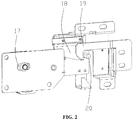
- a front end of the buckle plate 4 is provided with a first lock hook 18, as shown in FIG. 2
- the back of the locking arm 7 is correspondingly provided thereon with a lock column 20, and when the door lock device is closed, the first lock hook 18 is buckled on the lock column 20.
- a front end of the mounting plate 1 is provided thereon with a second lock hook 19, and when the landing door is closed in place, the second lock hook 19 is buckled on the lock column 20.
- a first contact switch head 2 is mounted on the mounting plate, the buckle plate is correspondingly provided thereon with a first contact switch base 3, and when a landing door is closed in place, the first contact switch head and the first contact switch base are closed with each other.
- a second contact switch head 6 is mounted on a front end of the locking arm, the buckle plate is correspondingly provided thereon with a second contact switch base 5, and when the door lock device is closed, the second contact switch head and the second contact switch base are closed with each other.
Landscapes
- Engineering & Computer Science (AREA)
- Automation & Control Theory (AREA)
- Mechanical Engineering (AREA)
- Elevator Door Apparatuses (AREA)
- Train Traffic Observation, Control, And Security (AREA)
Description
- The present invention relates to an elevator apparatus, and in particular, to an adjustable landing-door door lock device.
- The existing landing-door door lock device generally includes a primary lock and a secondary lock, a fixed ball and a moving ball of the primary lock are fixed onto a rotary locking arm at the same time, a fixed ball shaft serves as a center of rotation to be fixed with a bottom plate, positions of two lock balls are not adjustable, when there is a deviation between positions of a lock ball and a door knife of the landing-door door lock device on different floors, it is necessary to adjust the position of the whole door lock device, adjustment is complicated, and it is easy to result in poor contact of an electrical contact switch that proves effective closing of the door lock. For example, one device includes an upper sill, a left hanging plate and a right hanging plate slidingly disposed on the upper sill, a left landing door fixedly connected with the left hanging plate, and a right landing door fixedly connected with the right hanging plate, a fixed lock hook is fixedly mounted on the left hanging plate, a movable lock hook capable of turning over is mounted on the right hanging plate through a rotating shaft mechanism, two door balls are mounted on the movable lock hook, wherein one door ball serves as a rotating shaft, the door ball is adjustably fixed onto the bottom plate through a screw and a bolt, and distance adjustment can be carried out, but the two door balls cannot be adjusted separately. Moreover, rotation of the movable lock hook has no limiting structures, and an extreme position limiting function cannot be carried out on the movable lock hook. In addition, position adjustment on the door lock device is adjustment on the whole movable lock hook, which further causes the position of a contact switch mounted thereon and used to detect whether the landing door is closed or not is changed, it is necessary to re-adjust the position of the contact switch, operations are complicated, and a problem of poor contact of the contact switch exists.
-
DE 60 2004 008165 T2 discloses a landing-door door lock device according to the preamble ofclaim 1. - The present invention mainly solves the problem that the position of a lock ball of a general landing-door door lock device is not adjustable, and adjustment is complicated when there is a deviation between positions of the lock ball and a door knife, and provides a landing-door door lock device of which lock balls are adjusted separately and are convenient to adjust.
- Another invention objective of the present invention is to provide a landing-door door lock device that implements a function of limiting an extreme position.
- The technical solution adopted by the present invention to solve the technical problem thereof is: a landing-door door lock device, including a primary lock and a secondary lock, wherein the primary lock includes a bottom plate and a locking arm, a counter weight is mounted on the locking arm, a moving ball is fixed onto the counter weight, a fixed ball is mounted on the bottom plate, the secondary lock includes a buckle plate, the locking arm is rotationally connected onto the bottom plate through a rotary shaft, a rear end of the locking arm is provided with a first kidney-shaped hole, the counter weight is fixed with the locking arm through the kidney-shaped hole, an arc-shaped hole is opened on the counter weight, a shaft sleeve is sheathed on a shaft of the fixed ball, the shaft sleeve penetrates into the arc-shaped hole, a second kidney-shaped hole is opened on the bottom plate, the fixed ball is fixed with the bottom plate through the kidney-shaped hole, a front end of the buckle plate is provided with a first lock hook, the locking arm is correspondingly provided thereon with a lock column, and the first lock hook is buckled on the lock column. Compared with the existing landing-door door lock, in the present invention, the rotary shaft and the fixed ball are disposed separately, and the fixed ball and the moving ball are both fixed through kidney-shaped holes, so that the positions of the fixed ball and the moving ball can be adjusted separately; in this way, when there is a deviation between positions of the lock ball and the door knife of the landing-door door lock device on different floors, it is not necessary to adjust the position of the door lock of the whole floor, adjustment is simple, and a problem of poor contact occurring in electrical contacts on the door lock is avoided. The counter weight is mounted to the rear end of the locking arm, so that the front end of the locking arm is sticking up all the time, thereby ensuring that the primary lock is always keeping a tightened state with the secondary lock. The arc-shaped hole designed on the counter weight matches the shaft sleeve, which limits swing positions of the locking arm, that is, extreme positions of tightening and opening of the primary lock are limited.
- As one preferred solution of the foregoing solution, the landing-door door lock device further includes an interlock hook, the interlock hook includes a mounting plate, a front end of the mounting plate is provided with a second lock hook corresponding to the lock column, and the second lock hook is buckled on the lock column. When the landing door is closed in place, the interlock hook and the primary lock form locking. The interlock hook and the secondary lock form double locking for the landing door.
- As one preferred solution of the foregoing solution, a first contact switch head is mounted on the mounting plate, the buckle plate is correspondingly provided thereon with a first contact switch base, and when a landing door is closed in place, the first contact switch head and the first contact switch base are closed with each other. The first contact switch head and the first contact switch base jointly make up a first contact switch, and when the first contact switch is closed, it indicates that the landing door is closed in place.
- As one preferred solution of the foregoing solution, a second contact switch head is mounted on a front end of the locking arm, the buckle plate is correspondingly provided thereon with a second contact switch base, and when the door lock device is closed, the second contact switch head and the second contact switch base are closed with each other. The second contact switch head and the second contact switch base jointly make up a second contact switch, and when the second contact switch is closed, it indicates that the door lock device is closed in place.
- As one preferred solution of the foregoing solution, the locking arm is provided thereon with two first kidney-shaped holes, the two first kidney-shaped holes are respectively disposed in positions of upper and lower portions of the rear end of the locking arm, an upper portion of the counter weight is connected onto the first kidney-shaped hole located on the upper portion through a bolt, the bolt is fixed with the locking arm through a snap spring and a slider nut, the moving ball is correspondingly disposed at the lower portion of the counter weight, the counter weight is connected onto the other first kidney-shaped hole located on the lower portion through the moving ball, and the moving ball is fixed with the locking arm through a snap spring and a slider nut. The counter weight is fixed with the locking arm through a bolt and the moving ball, and the moving ball adopts a threaded connection manner, which facilitates later replacement of the lock ball. Use of the slider nut better facilitates the counter weight to slide to adjust the position, and at the same time, the snap spring ensures that the slider nut is not disconnected.
- As one preferred solution of the foregoing solution, the shaft sleeve is connected onto the second kidney-shaped hole of the bottom plate, the shaft sleeve is fixed with the bottom plate through a snap spring and a slider nut, and the fixed ball is in a threaded connection with the shaft sleeve. The fixed ball adopts a threaded connection manner, which facilitates later replacement of the lock ball.
- The present invention has the following advantages: the rotary shaft and the fixed ball are disposed separately, and the fixed ball and the moving ball are both fixed through kidney-shaped holes, so that the positions of the fixed ball and the moving ball can be adjusted left and right; in this way, when there is a deviation between positions of the lock ball and the door knife of the landing-door door lock device on different floors, it is not necessary to adjust the position of the door lock of the whole floor, so adjustment is simple, and a problem of poor contact occurring in electrical contacts on the door lock is also avoided.
-
-
FIG. 1 is a schematic view of an exploded structure of the present invention; and -
FIG. 2 is a schematic view of a back structure of the present invention. - 1-mounting plate 2-first contact switch head 3-first contact switch base 4-buckle plate 5-second contact switch base 6-second contact switch head 7-locking arm 8-rotary shaft 9-bolt 10-counter weight 11-fixed ball 12-moving ball 13-bottom 14-arc-shaped hole 15-shaft sleeve 16-first kidney-shaped hole 17-second kidney-shaped hole 18-first lock hook 19-second lock hook 20-lock column
- The technical solution of the present invention is further described below through embodiments and in combination with the accompanying drawings.
- This embodiment provides a landing-door door lock device, which, as shown in
FIG. 1 , includes three parts, i.e., a primary lock, a secondary lock and an interlock hook. The part of the primary lock includes a bottom plate 13, a locking arm 7, a fixed ball 11, a movingball 12 and acounter weight 10, the secondary lock includes abuckle plate 4, and the interlock hook includes amounting plate 1. - The bottom plate is mounted on a landing door, a middle portion of the locking arm is rotationally connected onto the bottom plate 13 through a
rotary shaft 8, and thecounter weight 10 is mounted onto a rear end of the locking arm. The counter weight is fixed through a bolt 9 and the movingball 12, a rear end part of the locking arm is provided thereon with two first kidney-shaped holes counter weight 10 is connected onto the kidney-shaped hole 16a located on the upper portion through the bolt 9, the bolt is fixed with the locking arm through a snap spring and a slider nut, the lower portion of thecounter weight 10 is connected onto the kidney-shaped hole 16b located on the lower portion through themoving ball 12, and the moving ball is fixed with the locking arm through a snap spring and a slider nut. - An arc-
shaped hole 14 is opened on thecounter weight 10, a groove is opened at a position where the locking arm 7 corresponds to the arc-shaped hole 14, ashaft sleeve 15 is sheathed on a shaft of the fixed ball 11, theshaft sleeve 15 penetrates into the arc-shaped hole 14, a second kidney-shaped hole 17 is opened on the bottom plate 13, a shaft of the fixed ball 11 penetrates through the arc-shaped hole 14 and the groove on the locking arm 7 to be connected onto the second kidney-shaped hole 17, and the fixed ball 11 is fixed with the bottom plate 13 through a snap spring and a slider nut. - A front end of the
buckle plate 4 is provided with afirst lock hook 18, as shown inFIG. 2 , the back of the locking arm 7 is correspondingly provided thereon with alock column 20, and when the door lock device is closed, thefirst lock hook 18 is buckled on thelock column 20. A front end of themounting plate 1 is provided thereon with asecond lock hook 19, and when the landing door is closed in place, thesecond lock hook 19 is buckled on thelock column 20. - A first
contact switch head 2 is mounted on the mounting plate, the buckle plate is correspondingly provided thereon with a firstcontact switch base 3, and when a landing door is closed in place, the first contact switch head and the first contact switch base are closed with each other. A secondcontact switch head 6 is mounted on a front end of the locking arm, the buckle plate is correspondingly provided thereon with a second contact switch base 5, and when the door lock device is closed, the second contact switch head and the second contact switch base are closed with each other. - During use of the landing-door door lock device, if there is a deviation between positions of a
lock ball 11, 12 and a door knife, it is feasible to respectively adjust themoving ball 12 and the fixed ball 11 separately, and the fixed ball 11 is kept penetrated into the arc-shaped hole 14 by adjusting positions of the bolt 9 and the movingball 12 on the first kidney-shaped holes counter weight 10 left and right and adjusting the position of the fixed ball 11 on the second kidney-shaped hole 17. In this way, positions of themoving ball 12 and the fixed ball 11 have been adjusted, but diameters of themoving ball 12 and the fixed ball 11 are not changed relative to the positions. - Specific embodiments described herein are merely illustrations for the present invention. Those skilled in the art can make various modifications or supplements to the specific embodiments described or replace the specific embodiments in a similar manner, which will not depart from the scope defined by the appended claims.
Claims (6)
- A landing-door door lock device, comprising a primary lock and a secondary lock, wherein the primary lock comprises a bottom plate (13) and a locking arm (7), a counter weight (10) is mounted on the locking arm (7), a moving ball (12) is fixed onto the counter weight (10), a fixed ball (11) is mounted on the bottom plate (13), and the secondary lock comprises a buckle plate (4), wherein the locking arm (7) is rotationally connected onto the bottom plate (13) through a rotary shaft (8), a rear end of the locking arm (7) is provided with a first kidney-shaped hole (16a), characterized in that the counter weight (10) is fixed with the locking arm (7) through the first kidney-shaped hole (16a), an arc-shaped hole (14) is opened on the counter weight (10), a shaft sleeve (15) is sheathed on a shaft of the fixed ball (11), the shaft sleeve (15) penetrates into the arc-shaped hole (14), a second kidney-shaped hole (17) is opened on the bottom plate (13), the fixed ball (11) is fixed with the bottom plate (13) through the second kidney-shaped hole (17), a front end of the buckle plate (4) is provided with a first lock hook (18), the locking arm (7) is correspondingly provided thereon with a lock column (20), and the first lock hook (18) is buckled on the lock column (20).
- The landing-door door lock device according to claim 1, characterized by: further comprising an interlock hook, wherein the interlock hook comprises a mounting plate (1), a front end of the mounting plate (1) is provided with a second lock hook (19) corresponding to the lock column (20), and the second lock hook (19) is buckled on the lock column (20).
- The landing-door door lock device according to claim 2, characterized in that: a first contact switch head (2) is mounted on the mounting plate (1), the buckle plate (4) is correspondingly provided thereon with a first contact switch base (3), and when a landing door is closed in place, the first contact switch head (2) and the first contact switch base (3) are closed with each other.
- The landing-door door lock device according to claim 1 or 2 or 3, characterized in that: a second contact switch head (6) is mounted on a front end of the locking arm (7), the buckle plate (4) is correspondingly provided thereon with a second contact switch base (5), and when the door lock device is closed, the second contact switch head (6) and the second contact switch base (5) are closed with each other.
- The landing-door door lock device according to claim 1 or 2 or 3, characterized in that: the locking arm (7) is provided thereon with two first kidney-shaped holes (16a, 16b), the two first kidney-shaped holes (16a, 16b) are respectively disposed in positions of upper and lower portions of the rear end of the locking arm (7), an upper portion of the counter weight (10) is connected onto the first kidney-shaped hole (16a) located on the upper portion through a bolt (9), the bolt (9) is fixed with the locking arm (7) through a snap spring and a slider nut, the moving ball (12) is correspondingly disposed at the lower portion of the counter weight (10), the counter weight (10) is connected onto the other first kidney-shaped hole (16b) located on the lower portion through the moving ball (12), and the moving ball (12) is fixed with the locking arm (7) through a snap spring and a slider nut.
- The landing-door door lock device according to claim 1 or 2 or 3, characterized in that: the shaft sleeve (15) is connected onto the second kidney-shaped hole (17) of the bottom plate (13), the shaft sleeve (15) is fixed with the bottom plate (13) through a snap spring and a slider nut, and the fixed ball (11) is in a threaded connection with the shaft sleeve (15).
Applications Claiming Priority (2)
| Application Number | Priority Date | Filing Date | Title |
|---|---|---|---|
| CN201410697260.9A CN104743429B (en) | 2014-11-27 | 2014-11-27 | A kind of inlay door locking device |
| PCT/US2015/060668 WO2016085678A1 (en) | 2014-11-27 | 2015-11-13 | Landing-door door lock device |
Publications (2)
| Publication Number | Publication Date |
|---|---|
| EP3224183A1 EP3224183A1 (en) | 2017-10-04 |
| EP3224183B1 true EP3224183B1 (en) | 2019-10-30 |
Family
ID=53583814
Family Applications (1)
| Application Number | Title | Priority Date | Filing Date |
|---|---|---|---|
| EP15801066.0A Active EP3224183B1 (en) | 2014-11-27 | 2015-11-13 | Landing-door door lock device |
Country Status (4)
| Country | Link |
|---|---|
| US (1) | US10189680B2 (en) |
| EP (1) | EP3224183B1 (en) |
| CN (1) | CN104743429B (en) |
| WO (1) | WO2016085678A1 (en) |
Families Citing this family (16)
| Publication number | Priority date | Publication date | Assignee | Title |
|---|---|---|---|---|
| IT201700052995A1 (en) * | 2017-05-16 | 2018-11-16 | Wittur Holding Gmbh | LOCK ASSEMBLY, LIFT SYSTEM |
| CN107265268B (en) * | 2017-07-10 | 2023-03-31 | 浙江优迈重工机械有限公司 | Elevator door lock device |
| CN108190702A (en) * | 2018-02-06 | 2018-06-22 | 上海贝思特门机有限公司 | A kind of elevator hall door lock device |
| US11040858B2 (en) | 2018-05-01 | 2021-06-22 | Otis Elevator Company | Elevator door interlock assembly |
| US11034548B2 (en) | 2018-05-01 | 2021-06-15 | Otis Elevator Company | Elevator door interlock assembly |
| US11040852B2 (en) | 2018-05-01 | 2021-06-22 | Otis Elevator Company | Elevator car control to address abnormal passenger behavior |
| US11155444B2 (en) | 2018-05-01 | 2021-10-26 | Otis Elevator Company | Elevator door interlock assembly |
| US11046557B2 (en) | 2018-05-01 | 2021-06-29 | Otis Elevator Company | Elevator door interlock assembly |
| USD911811S1 (en) * | 2018-10-31 | 2021-03-02 | Stylgame S.R.L. | Seat locking device |
| CN112551328A (en) * | 2020-12-01 | 2021-03-26 | 宁波申菱机电科技股份有限公司 | Single-knife movable asynchronous door knife device |
| CN115676568A (en) * | 2021-07-27 | 2023-02-03 | 奥的斯电梯公司 | Elevator door interlocking assembly and elevator system |
| CN113602942A (en) * | 2021-08-06 | 2021-11-05 | 浙江昊崛电梯配件有限公司 | Elevator switch dustproof construction |
| US11760604B1 (en) | 2022-05-27 | 2023-09-19 | Otis Elevator Company | Versatile elevator door interlock assembly |
| CN116750613B (en) * | 2023-04-24 | 2025-08-08 | 苏州和阳智能制造股份有限公司 | A synchronous door knife |
| CN117735370B (en) * | 2024-01-18 | 2026-05-01 | 展鹏科技股份有限公司 | Explosion-proof elevator car door lock device and control method |
| CN119429897B (en) * | 2025-01-13 | 2025-04-11 | 三门县中盈科技股份有限公司 | A test fixture for testing elevator door sword is durable |
Family Cites Families (27)
| Publication number | Priority date | Publication date | Assignee | Title |
|---|---|---|---|---|
| US1816072A (en) * | 1927-02-18 | 1931-07-28 | Otis Elevator Co | Electromechanical interlock |
| US1765526A (en) * | 1928-12-10 | 1930-06-24 | Glaser Herbert | Lock |
| US2060283A (en) * | 1935-11-13 | 1936-11-10 | Harry R Cullmer | Elevator car control |
| US2287751A (en) * | 1940-09-27 | 1942-06-23 | Emory W Fenn | Interlock for elevator doors |
| US3239030A (en) * | 1963-10-22 | 1966-03-08 | Harris Preble Fire Doors Inc | Elevator door lock and control |
| SE372239B (en) * | 1973-04-26 | 1974-12-16 | Linden Alimak Ab | |
| US4149615A (en) * | 1977-09-15 | 1979-04-17 | Westinghouse Electric Corp. | Apparatus for mounting an elevator door operator |
| US5730254A (en) * | 1995-07-21 | 1998-03-24 | Vertisys, Inc. | Elevator door restraint device |
| FI100517B (en) * | 1995-09-13 | 1997-12-31 | Kone Oy | Method of closing the elevator level door and the participant |
| ES2207696T3 (en) * | 1996-10-29 | 2004-06-01 | Inventio Ag | DEVICE FOR OPENING AND CLOSING A CABIN DOOR AND A BOX DOOR OF AN ELEVATOR INSTALLATION. |
| JP4406136B2 (en) * | 1999-12-10 | 2010-01-27 | オーチス エレベータ カンパニー | Elevator door equipment |
| US6474448B1 (en) * | 2000-01-26 | 2002-11-05 | Sematic Italia S.P.A. | Modular lock for elevator doors |
| US6220396B1 (en) * | 2000-03-10 | 2001-04-24 | Thyssen Dover Elevator | Door restrictor apparatus for elevators |
| US6591946B2 (en) * | 2001-10-11 | 2003-07-15 | Inventio Ag | Adjustable door restrictor cable for an elevator car |
| FR2858002B1 (en) * | 2003-07-22 | 2005-09-02 | Thyssenkrupp Elevator Mfg F | METHOD FOR ADJUSTING AN ELEVATOR LEVEL DOOR LOCK |
| ZA200406978B (en) * | 2003-09-17 | 2005-06-20 | Inventio Ag | Device for connecting a cage door with a shaft door and for locking and unlocking the doors, a device for emergency unlocking of a cage door and a method for emergency unlocking of a cage door. |
| JP4708005B2 (en) * | 2003-12-08 | 2011-06-22 | インベンテイオ・アクテイエンゲゼルシヤフト | Apparatus in an elevator car for temporarily connecting a cage door leaf to a hoistway door leaf and activating a cage door unlocking means |
| US7464794B2 (en) * | 2004-03-22 | 2008-12-16 | Otis Elevator Company | Coupling device for elevator car doors and landing doors |
| JP4544887B2 (en) * | 2004-03-26 | 2010-09-15 | 東芝エレベータ株式会社 | Elevator door device |
| EP1863733B1 (en) * | 2005-02-03 | 2008-12-03 | Otis Elevator Company | Safety lock for elevator landing door detecting intrusion in the shaft through the landing door and elevator thus equipped |
| CN2934169Y (en) * | 2006-05-18 | 2007-08-15 | 龚根明 | Adjustable automatic gate locking device |
| US7398862B2 (en) * | 2006-06-02 | 2008-07-15 | The Peelle Company Ltd. | Car door lock |
| ES2603829T3 (en) * | 2006-09-28 | 2017-03-01 | Inventio Ag | Procedure for the modernization of an elevator door system of an elevator installation and modernization kit for carrying out the procedure |
| CN201610672U (en) * | 2010-01-29 | 2010-10-20 | 上海贝思特门机有限公司 | Elevator hall door lock device |
| JP2012218834A (en) * | 2011-04-05 | 2012-11-12 | Mitsubishi Electric Corp | Locking device of elevator landing |
| CN103723605B (en) * | 2013-09-23 | 2015-08-26 | 西子奥的斯电梯有限公司 | The asynchronous door cutter of the integrated car door lock of a kind of elevator |
| CN203653024U (en) * | 2013-12-23 | 2014-06-18 | 申龙电梯股份有限公司 | Door lock device of elevator landing doors |
-
2014
- 2014-11-27 CN CN201410697260.9A patent/CN104743429B/en active Active
-
2015
- 2015-11-13 EP EP15801066.0A patent/EP3224183B1/en active Active
- 2015-11-13 WO PCT/US2015/060668 patent/WO2016085678A1/en not_active Ceased
- 2015-11-13 US US15/529,327 patent/US10189680B2/en active Active
Non-Patent Citations (1)
| Title |
|---|
| None * |
Also Published As
| Publication number | Publication date |
|---|---|
| WO2016085678A1 (en) | 2016-06-02 |
| CN104743429A (en) | 2015-07-01 |
| US10189680B2 (en) | 2019-01-29 |
| CN104743429B (en) | 2016-09-21 |
| EP3224183A1 (en) | 2017-10-04 |
| US20170267495A1 (en) | 2017-09-21 |
Similar Documents
| Publication | Publication Date | Title |
|---|---|---|
| US10189680B2 (en) | Landing-door door lock device | |
| US9400083B2 (en) | Support apparatus for multiple display devices | |
| US20120117757A1 (en) | Biaxial hinge device | |
| CN109236708B (en) | Fan with fan body | |
| EP2725175B1 (en) | Adjustable hinge | |
| CN102939431B (en) | Wear pad adjustment assembly | |
| US9493094B2 (en) | Seat tilt angle control device | |
| DK3208820T3 (en) | Rotary control system for a device | |
| WO2017165355A3 (en) | Door handle with adjustable pull mounting mechanism | |
| EP2243913B1 (en) | Support particularly for doors, sliding door wings and the like | |
| US9604385B2 (en) | Electric trimmer | |
| US9802307B2 (en) | Locking intermediate link for a tool arm assembly | |
| US8911010B2 (en) | Pivoting swing seat with control system | |
| KR102964199B1 (en) | Adjustable hinge for wearable devices | |
| AU2011218735B2 (en) | Adjustable shower arm | |
| CN219412346U (en) | Cabinet door installation auxiliary device | |
| JP6047624B2 (en) | Equipment support device | |
| CN214145146U (en) | Buffer trigger device and sliding door system | |
| CN201567879U (en) | Adjustable type convenient top lock device | |
| JP6537880B2 (en) | Hinge | |
| WO2017059909A1 (en) | Adjustable hinge assembly for use in a refrigerator | |
| WO2019144407A1 (en) | Damping device, wheel device, and remote controller | |
| CN104492967A (en) | Sliding block applied to terminal crimping die | |
| US1581956A (en) | Telephone stand | |
| AU2016100533A4 (en) | A multipurpose LED light supplement lamp |
Legal Events
| Date | Code | Title | Description |
|---|---|---|---|
| STAA | Information on the status of an ep patent application or granted ep patent |
Free format text: STATUS: THE INTERNATIONAL PUBLICATION HAS BEEN MADE |
|
| PUAI | Public reference made under article 153(3) epc to a published international application that has entered the european phase |
Free format text: ORIGINAL CODE: 0009012 |
|
| STAA | Information on the status of an ep patent application or granted ep patent |
Free format text: STATUS: REQUEST FOR EXAMINATION WAS MADE |
|
| 17P | Request for examination filed |
Effective date: 20170627 |
|
| AK | Designated contracting states |
Kind code of ref document: A1 Designated state(s): AL AT BE BG CH CY CZ DE DK EE ES FI FR GB GR HR HU IE IS IT LI LT LU LV MC MK MT NL NO PL PT RO RS SE SI SK SM TR |
|
| AX | Request for extension of the european patent |
Extension state: BA ME |
|
| DAV | Request for validation of the european patent (deleted) | ||
| DAX | Request for extension of the european patent (deleted) | ||
| GRAP | Despatch of communication of intention to grant a patent |
Free format text: ORIGINAL CODE: EPIDOSNIGR1 |
|
| STAA | Information on the status of an ep patent application or granted ep patent |
Free format text: STATUS: GRANT OF PATENT IS INTENDED |
|
| INTG | Intention to grant announced |
Effective date: 20190513 |
|
| GRAS | Grant fee paid |
Free format text: ORIGINAL CODE: EPIDOSNIGR3 |
|
| GRAA | (expected) grant |
Free format text: ORIGINAL CODE: 0009210 |
|
| STAA | Information on the status of an ep patent application or granted ep patent |
Free format text: STATUS: THE PATENT HAS BEEN GRANTED |
|
| AK | Designated contracting states |
Kind code of ref document: B1 Designated state(s): AL AT BE BG CH CY CZ DE DK EE ES FI FR GB GR HR HU IE IS IT LI LT LU LV MC MK MT NL NO PL PT RO RS SE SI SK SM TR |
|
| REG | Reference to a national code |
Ref country code: GB Ref legal event code: FG4D |
|
| REG | Reference to a national code |
Ref country code: CH Ref legal event code: EP |
|
| REG | Reference to a national code |
Ref country code: AT Ref legal event code: REF Ref document number: 1195916 Country of ref document: AT Kind code of ref document: T Effective date: 20191115 |
|
| REG | Reference to a national code |
Ref country code: DE Ref legal event code: R096 Ref document number: 602015040787 Country of ref document: DE |
|
| REG | Reference to a national code |
Ref country code: IE Ref legal event code: FG4D |
|
| REG | Reference to a national code |
Ref country code: LT Ref legal event code: MG4D |
|
| PG25 | Lapsed in a contracting state [announced via postgrant information from national office to epo] |
Ref country code: LT Free format text: LAPSE BECAUSE OF FAILURE TO SUBMIT A TRANSLATION OF THE DESCRIPTION OR TO PAY THE FEE WITHIN THE PRESCRIBED TIME-LIMIT Effective date: 20191030 Ref country code: PT Free format text: LAPSE BECAUSE OF FAILURE TO SUBMIT A TRANSLATION OF THE DESCRIPTION OR TO PAY THE FEE WITHIN THE PRESCRIBED TIME-LIMIT Effective date: 20200302 Ref country code: NL Free format text: LAPSE BECAUSE OF FAILURE TO SUBMIT A TRANSLATION OF THE DESCRIPTION OR TO PAY THE FEE WITHIN THE PRESCRIBED TIME-LIMIT Effective date: 20191030 Ref country code: FI Free format text: LAPSE BECAUSE OF FAILURE TO SUBMIT A TRANSLATION OF THE DESCRIPTION OR TO PAY THE FEE WITHIN THE PRESCRIBED TIME-LIMIT Effective date: 20191030 Ref country code: BG Free format text: LAPSE BECAUSE OF FAILURE TO SUBMIT A TRANSLATION OF THE DESCRIPTION OR TO PAY THE FEE WITHIN THE PRESCRIBED TIME-LIMIT Effective date: 20200130 Ref country code: GR Free format text: LAPSE BECAUSE OF FAILURE TO SUBMIT A TRANSLATION OF THE DESCRIPTION OR TO PAY THE FEE WITHIN THE PRESCRIBED TIME-LIMIT Effective date: 20200131 Ref country code: PL Free format text: LAPSE BECAUSE OF FAILURE TO SUBMIT A TRANSLATION OF THE DESCRIPTION OR TO PAY THE FEE WITHIN THE PRESCRIBED TIME-LIMIT Effective date: 20191030 Ref country code: NO Free format text: LAPSE BECAUSE OF FAILURE TO SUBMIT A TRANSLATION OF THE DESCRIPTION OR TO PAY THE FEE WITHIN THE PRESCRIBED TIME-LIMIT Effective date: 20200130 Ref country code: SE Free format text: LAPSE BECAUSE OF FAILURE TO SUBMIT A TRANSLATION OF THE DESCRIPTION OR TO PAY THE FEE WITHIN THE PRESCRIBED TIME-LIMIT Effective date: 20191030 Ref country code: LV Free format text: LAPSE BECAUSE OF FAILURE TO SUBMIT A TRANSLATION OF THE DESCRIPTION OR TO PAY THE FEE WITHIN THE PRESCRIBED TIME-LIMIT Effective date: 20191030 |
|
| REG | Reference to a national code |
Ref country code: NL Ref legal event code: MP Effective date: 20191030 |
|
| PG25 | Lapsed in a contracting state [announced via postgrant information from national office to epo] |
Ref country code: RS Free format text: LAPSE BECAUSE OF FAILURE TO SUBMIT A TRANSLATION OF THE DESCRIPTION OR TO PAY THE FEE WITHIN THE PRESCRIBED TIME-LIMIT Effective date: 20191030 Ref country code: HR Free format text: LAPSE BECAUSE OF FAILURE TO SUBMIT A TRANSLATION OF THE DESCRIPTION OR TO PAY THE FEE WITHIN THE PRESCRIBED TIME-LIMIT Effective date: 20191030 Ref country code: IS Free format text: LAPSE BECAUSE OF FAILURE TO SUBMIT A TRANSLATION OF THE DESCRIPTION OR TO PAY THE FEE WITHIN THE PRESCRIBED TIME-LIMIT Effective date: 20200229 |
|
| PG25 | Lapsed in a contracting state [announced via postgrant information from national office to epo] |
Ref country code: AL Free format text: LAPSE BECAUSE OF FAILURE TO SUBMIT A TRANSLATION OF THE DESCRIPTION OR TO PAY THE FEE WITHIN THE PRESCRIBED TIME-LIMIT Effective date: 20191030 |
|
| REG | Reference to a national code |
Ref country code: CH Ref legal event code: PL |
|
| PG25 | Lapsed in a contracting state [announced via postgrant information from national office to epo] |
Ref country code: RO Free format text: LAPSE BECAUSE OF FAILURE TO SUBMIT A TRANSLATION OF THE DESCRIPTION OR TO PAY THE FEE WITHIN THE PRESCRIBED TIME-LIMIT Effective date: 20191030 Ref country code: LI Free format text: LAPSE BECAUSE OF NON-PAYMENT OF DUE FEES Effective date: 20191130 Ref country code: CZ Free format text: LAPSE BECAUSE OF FAILURE TO SUBMIT A TRANSLATION OF THE DESCRIPTION OR TO PAY THE FEE WITHIN THE PRESCRIBED TIME-LIMIT Effective date: 20191030 Ref country code: MC Free format text: LAPSE BECAUSE OF FAILURE TO SUBMIT A TRANSLATION OF THE DESCRIPTION OR TO PAY THE FEE WITHIN THE PRESCRIBED TIME-LIMIT Effective date: 20191030 Ref country code: DK Free format text: LAPSE BECAUSE OF FAILURE TO SUBMIT A TRANSLATION OF THE DESCRIPTION OR TO PAY THE FEE WITHIN THE PRESCRIBED TIME-LIMIT Effective date: 20191030 Ref country code: ES Free format text: LAPSE BECAUSE OF FAILURE TO SUBMIT A TRANSLATION OF THE DESCRIPTION OR TO PAY THE FEE WITHIN THE PRESCRIBED TIME-LIMIT Effective date: 20191030 Ref country code: CH Free format text: LAPSE BECAUSE OF NON-PAYMENT OF DUE FEES Effective date: 20191130 Ref country code: LU Free format text: LAPSE BECAUSE OF NON-PAYMENT OF DUE FEES Effective date: 20191113 Ref country code: EE Free format text: LAPSE BECAUSE OF FAILURE TO SUBMIT A TRANSLATION OF THE DESCRIPTION OR TO PAY THE FEE WITHIN THE PRESCRIBED TIME-LIMIT Effective date: 20191030 |
|
| REG | Reference to a national code |
Ref country code: DE Ref legal event code: R097 Ref document number: 602015040787 Country of ref document: DE |
|
| REG | Reference to a national code |
Ref country code: AT Ref legal event code: MK05 Ref document number: 1195916 Country of ref document: AT Kind code of ref document: T Effective date: 20191030 |
|
| REG | Reference to a national code |
Ref country code: BE Ref legal event code: MM Effective date: 20191130 |
|
| PG25 | Lapsed in a contracting state [announced via postgrant information from national office to epo] |
Ref country code: SK Free format text: LAPSE BECAUSE OF FAILURE TO SUBMIT A TRANSLATION OF THE DESCRIPTION OR TO PAY THE FEE WITHIN THE PRESCRIBED TIME-LIMIT Effective date: 20191030 Ref country code: SM Free format text: LAPSE BECAUSE OF FAILURE TO SUBMIT A TRANSLATION OF THE DESCRIPTION OR TO PAY THE FEE WITHIN THE PRESCRIBED TIME-LIMIT Effective date: 20191030 Ref country code: IT Free format text: LAPSE BECAUSE OF FAILURE TO SUBMIT A TRANSLATION OF THE DESCRIPTION OR TO PAY THE FEE WITHIN THE PRESCRIBED TIME-LIMIT Effective date: 20191030 |
|
| PLBE | No opposition filed within time limit |
Free format text: ORIGINAL CODE: 0009261 |
|
| STAA | Information on the status of an ep patent application or granted ep patent |
Free format text: STATUS: NO OPPOSITION FILED WITHIN TIME LIMIT |
|
| GBPC | Gb: european patent ceased through non-payment of renewal fee |
Effective date: 20200130 |
|
| 26N | No opposition filed |
Effective date: 20200731 |
|
| PG25 | Lapsed in a contracting state [announced via postgrant information from national office to epo] |
Ref country code: GB Free format text: LAPSE BECAUSE OF NON-PAYMENT OF DUE FEES Effective date: 20200130 Ref country code: IE Free format text: LAPSE BECAUSE OF NON-PAYMENT OF DUE FEES Effective date: 20191113 |
|
| PG25 | Lapsed in a contracting state [announced via postgrant information from national office to epo] |
Ref country code: SI Free format text: LAPSE BECAUSE OF FAILURE TO SUBMIT A TRANSLATION OF THE DESCRIPTION OR TO PAY THE FEE WITHIN THE PRESCRIBED TIME-LIMIT Effective date: 20191030 Ref country code: BE Free format text: LAPSE BECAUSE OF NON-PAYMENT OF DUE FEES Effective date: 20191130 Ref country code: AT Free format text: LAPSE BECAUSE OF FAILURE TO SUBMIT A TRANSLATION OF THE DESCRIPTION OR TO PAY THE FEE WITHIN THE PRESCRIBED TIME-LIMIT Effective date: 20191030 |
|
| PG25 | Lapsed in a contracting state [announced via postgrant information from national office to epo] |
Ref country code: CY Free format text: LAPSE BECAUSE OF FAILURE TO SUBMIT A TRANSLATION OF THE DESCRIPTION OR TO PAY THE FEE WITHIN THE PRESCRIBED TIME-LIMIT Effective date: 20191030 |
|
| PG25 | Lapsed in a contracting state [announced via postgrant information from national office to epo] |
Ref country code: HU Free format text: LAPSE BECAUSE OF FAILURE TO SUBMIT A TRANSLATION OF THE DESCRIPTION OR TO PAY THE FEE WITHIN THE PRESCRIBED TIME-LIMIT; INVALID AB INITIO Effective date: 20151113 Ref country code: MT Free format text: LAPSE BECAUSE OF FAILURE TO SUBMIT A TRANSLATION OF THE DESCRIPTION OR TO PAY THE FEE WITHIN THE PRESCRIBED TIME-LIMIT Effective date: 20191030 |
|
| PG25 | Lapsed in a contracting state [announced via postgrant information from national office to epo] |
Ref country code: TR Free format text: LAPSE BECAUSE OF FAILURE TO SUBMIT A TRANSLATION OF THE DESCRIPTION OR TO PAY THE FEE WITHIN THE PRESCRIBED TIME-LIMIT Effective date: 20191030 |
|
| PG25 | Lapsed in a contracting state [announced via postgrant information from national office to epo] |
Ref country code: MK Free format text: LAPSE BECAUSE OF FAILURE TO SUBMIT A TRANSLATION OF THE DESCRIPTION OR TO PAY THE FEE WITHIN THE PRESCRIBED TIME-LIMIT Effective date: 20191030 |
|
| PGFP | Annual fee paid to national office [announced via postgrant information from national office to epo] |
Ref country code: DE Payment date: 20251022 Year of fee payment: 11 |
|
| PGFP | Annual fee paid to national office [announced via postgrant information from national office to epo] |
Ref country code: FR Payment date: 20251022 Year of fee payment: 11 |