EP3224079B1 - Inverter with improved safety - Google Patents
Inverter with improved safety Download PDFInfo
- Publication number
- EP3224079B1 EP3224079B1 EP15820211.9A EP15820211A EP3224079B1 EP 3224079 B1 EP3224079 B1 EP 3224079B1 EP 15820211 A EP15820211 A EP 15820211A EP 3224079 B1 EP3224079 B1 EP 3224079B1
- Authority
- EP
- European Patent Office
- Prior art keywords
- switches
- processing unit
- inverter
- malfunction
- power supply
- Prior art date
- Legal status (The legal status is an assumption and is not a legal conclusion. Google has not performed a legal analysis and makes no representation as to the accuracy of the status listed.)
- Active
Links
- 230000007257 malfunction Effects 0.000 claims description 131
- 238000012545 processing Methods 0.000 claims description 128
- 238000000034 method Methods 0.000 claims description 15
- 238000012544 monitoring process Methods 0.000 description 20
- 238000005036 potential barrier Methods 0.000 description 8
- 230000009471 action Effects 0.000 description 6
- 238000001514 detection method Methods 0.000 description 5
- 238000010586 diagram Methods 0.000 description 5
- 230000002093 peripheral effect Effects 0.000 description 3
- 238000004891 communication Methods 0.000 description 2
- 230000005669 field effect Effects 0.000 description 2
- 238000011065 in-situ storage Methods 0.000 description 2
- 229910044991 metal oxide Inorganic materials 0.000 description 2
- 150000004706 metal oxides Chemical class 0.000 description 2
- 238000004092 self-diagnosis Methods 0.000 description 2
- 230000002159 abnormal effect Effects 0.000 description 1
- 238000003491 array Methods 0.000 description 1
- 230000004888 barrier function Effects 0.000 description 1
- 238000011161 development Methods 0.000 description 1
- 230000004064 dysfunction Effects 0.000 description 1
- 238000010292 electrical insulation Methods 0.000 description 1
- 239000012212 insulator Substances 0.000 description 1
- 238000002955 isolation Methods 0.000 description 1
- 230000004044 response Effects 0.000 description 1
- 239000004065 semiconductor Substances 0.000 description 1
- 239000007787 solid Substances 0.000 description 1
Images


Classifications
-
- B—PERFORMING OPERATIONS; TRANSPORTING
- B60—VEHICLES IN GENERAL
- B60L—PROPULSION OF ELECTRICALLY-PROPELLED VEHICLES; SUPPLYING ELECTRIC POWER FOR AUXILIARY EQUIPMENT OF ELECTRICALLY-PROPELLED VEHICLES; ELECTRODYNAMIC BRAKE SYSTEMS FOR VEHICLES IN GENERAL; MAGNETIC SUSPENSION OR LEVITATION FOR VEHICLES; MONITORING OPERATING VARIABLES OF ELECTRICALLY-PROPELLED VEHICLES; ELECTRIC SAFETY DEVICES FOR ELECTRICALLY-PROPELLED VEHICLES
- B60L3/00—Electric devices on electrically-propelled vehicles for safety purposes; Monitoring operating variables, e.g. speed, deceleration or energy consumption
- B60L3/0023—Detecting, eliminating, remedying or compensating for drive train abnormalities, e.g. failures within the drive train
- B60L3/003—Detecting, eliminating, remedying or compensating for drive train abnormalities, e.g. failures within the drive train relating to inverters
-
- H—ELECTRICITY
- H02—GENERATION; CONVERSION OR DISTRIBUTION OF ELECTRIC POWER
- H02H—EMERGENCY PROTECTIVE CIRCUIT ARRANGEMENTS
- H02H7/00—Emergency protective circuit arrangements specially adapted for specific types of electric machines or apparatus or for sectionalised protection of cable or line systems, and effecting automatic switching in the event of an undesired change from normal working conditions
- H02H7/10—Emergency protective circuit arrangements specially adapted for specific types of electric machines or apparatus or for sectionalised protection of cable or line systems, and effecting automatic switching in the event of an undesired change from normal working conditions for converters; for rectifiers
- H02H7/12—Emergency protective circuit arrangements specially adapted for specific types of electric machines or apparatus or for sectionalised protection of cable or line systems, and effecting automatic switching in the event of an undesired change from normal working conditions for converters; for rectifiers for static converters or rectifiers
- H02H7/122—Emergency protective circuit arrangements specially adapted for specific types of electric machines or apparatus or for sectionalised protection of cable or line systems, and effecting automatic switching in the event of an undesired change from normal working conditions for converters; for rectifiers for static converters or rectifiers for inverters, i.e. dc/ac converters
- H02H7/1225—Emergency protective circuit arrangements specially adapted for specific types of electric machines or apparatus or for sectionalised protection of cable or line systems, and effecting automatic switching in the event of an undesired change from normal working conditions for converters; for rectifiers for static converters or rectifiers for inverters, i.e. dc/ac converters responsive to internal faults, e.g. shoot-through
-
- H—ELECTRICITY
- H02—GENERATION; CONVERSION OR DISTRIBUTION OF ELECTRIC POWER
- H02M—APPARATUS FOR CONVERSION BETWEEN AC AND AC, BETWEEN AC AND DC, OR BETWEEN DC AND DC, AND FOR USE WITH MAINS OR SIMILAR POWER SUPPLY SYSTEMS; CONVERSION OF DC OR AC INPUT POWER INTO SURGE OUTPUT POWER; CONTROL OR REGULATION THEREOF
- H02M1/00—Details of apparatus for conversion
- H02M1/32—Means for protecting converters other than automatic disconnection
-
- H—ELECTRICITY
- H02—GENERATION; CONVERSION OR DISTRIBUTION OF ELECTRIC POWER
- H02P—CONTROL OR REGULATION OF ELECTRIC MOTORS, ELECTRIC GENERATORS OR DYNAMO-ELECTRIC CONVERTERS; CONTROLLING TRANSFORMERS, REACTORS OR CHOKE COILS
- H02P29/00—Arrangements for regulating or controlling electric motors, appropriate for both AC and DC motors
- H02P29/02—Providing protection against overload without automatic interruption of supply
- H02P29/024—Detecting a fault condition, e.g. short circuit, locked rotor, open circuit or loss of load
- H02P29/0243—Detecting a fault condition, e.g. short circuit, locked rotor, open circuit or loss of load the fault being a broken phase
-
- Y—GENERAL TAGGING OF NEW TECHNOLOGICAL DEVELOPMENTS; GENERAL TAGGING OF CROSS-SECTIONAL TECHNOLOGIES SPANNING OVER SEVERAL SECTIONS OF THE IPC; TECHNICAL SUBJECTS COVERED BY FORMER USPC CROSS-REFERENCE ART COLLECTIONS [XRACs] AND DIGESTS
- Y02—TECHNOLOGIES OR APPLICATIONS FOR MITIGATION OR ADAPTATION AGAINST CLIMATE CHANGE
- Y02T—CLIMATE CHANGE MITIGATION TECHNOLOGIES RELATED TO TRANSPORTATION
- Y02T10/00—Road transport of goods or passengers
- Y02T10/60—Other road transportation technologies with climate change mitigation effect
- Y02T10/64—Electric machine technologies in electromobility
Definitions
- the present invention relates to the field of inverters and in particular to power inverters used in motor vehicles.
- inverters are used in electric or hybrid vehicles to convert the direct current supplied by batteries, generally high voltage, into alternating current to power the electric motor.
- Another solution consists in doubling certain elements linked to the control electronics and in using “OR” logic functions to generate a command in the event of a malfunction of one of the two elements.
- OR logic functions
- the doubling of the elements linked to the control electronics entails an additional cost and can pose synchronization problems if two elements have to send a message simultaneously following a malfunction.
- the subject of the present invention is therefore an inverter according to claim 1 and a method according to claim 19.
- the use of two power sources to independently power the high side and the low side of the inverter combined with the use of two logic components placed respectively on the high side and the low side allows to be able to short-circuit the switches on the high or low side of the inverter in the event of a malfunction of one of the inverter elements.
- the short-circuiting of the switches on one side of the inverter makes it possible to control the electromotive force created by the magnets of the rotor and thus to put the electric motor and therefore the vehicle in freewheel.
- the short-circuiting of the first switches corresponds to a closing of the first switches and an opening of the second switches; and the short-circuiting of the second switches corresponds to a closing of the second switches and an opening of the first switches.
- the inverter also comprises a processing unit intended to communicate on the one hand with a control unit and on the other hand with the first and the second logic component.
- the processing unit is configured to detect a malfunction of an element of the high side or the low side.
- the inverter also comprises a plurality of comparators whose inputs are connected respectively to the midpoints of the branches and whose outputs are connected to the processing unit, the comparators being configured to compare a electrical quantity from their respective midpoint to a value which depends on the configuration of the switches, the processing unit being configured to detect a malfunction of an element on the high side or on the low side from a difference between said quantity electrical and said value.
- the processing unit is configured to detect a malfunction of an element on the high side, respectively of an element on the low side, from control signals sent by said logic component on the high side, respectively by said logic component on the low side.
- the logic components on the high side and / or on the low side are configured to detect a malfunction of the processing unit from control signals sent by said processing unit.
- the processing unit is configured to control the short-circuiting of the first or second switches as a function of a malfunction of an element on the high side or on the low side.
- the logic components on the low side and on the high side are configured to control the short-circuiting of the second, respectively of the first, switches in the event of a malfunction of the processing unit.
- control unit is included in the inverter.
- control unit is configured to detect a malfunction of the processing unit, and / or the processing unit is configured to detect a malfunction of the control unit.
- control unit is configured to detect a malfunction of the processing unit from control signals sent by said processing unit, and / or the processing unit is configured to detect a malfunction. of the control unit from control signals sent by said control unit.
- the processing unit or the control unit are configured to control the short-circuiting of the second, or the first, switches in the event of a malfunction.
- control unit or the processing unit are configured to control the short-circuiting of the first or second switches by means of permission signals making it possible to activate or deactivate the first or second. switches.
- control unit is configured to send permission signals to the high side to enable or disable the switches on the high side
- processing unit is configured to send permission signals to the high side.
- the low side to activate or deactivate the switches on the low side; or the control unit is configured to send permission signals to the low side to enable or disable the low side switches, and the processing unit is configured to send permission signals to the high side to enable '' activate or deactivate the switches on the high side.
- the processing unit is a separate element from the control unit.
- the inverter is configured to supply an electric motor of a motor vehicle from the first power source or from the second power source.
- the high side comprises first control units
- the low side comprises second control units
- the first and second switches being controlled respectively via the first and the second control units.
- control signals are monitoring signals or error signals.
- the processing unit and the control unit are both powered by the first, respectively the second, power source.
- the processing unit is supplied by the first, respectively the second, power source; and the control unit is powered by the second, respectively the first, power source.
- the present invention also relates to a method for controlling an inverter according to claim 19, in which in the event of a malfunction of the processing unit, the first logic component, respectively the second logic component, detects said malfunction of the processing unit. from the control signals sent by said processing unit and controls the short-circuiting of the first, respectively of the second, switches.
- the present invention also relates to a method for controlling an inverter according to the invention in which, in the event of a malfunction of an element on the high side or of an element on the low side, the processing unit detects said malfunction and controls short-circuiting the first switches or the second switches depending on the type of malfunction.
- the present invention further relates to a method for controlling an inverter according to the invention in which, in the event of a malfunction of the control unit, the processing unit detects said malfunction of the control unit from the signals. signals sent by the control unit and commands the short-circuiting of the first or second switches.
- the present invention also relates to a method of controlling an inverter according to the invention in which the processing unit and the control unit are both supplied by the first, respectively the second, power source and in which in the event of a malfunction of the first, respectively of the second, power source, the second, respectively the first, logic component controls the short-circuiting of the second, respectively of the first, switches.
- the present invention also relates to a method for controlling an inverter according to the invention in which the processing unit is powered by the first, respectively the second, power source, and the control unit is powered by the second, respectively the first power source; and in the event of a malfunction of the power source supplying the control unit, the processing unit controls the short-circuiting of the switches supplied by its power source; and in the event of a malfunction of the power source supplying the processing unit, the logic component supplied by the other supply source controls the short-circuiting of the switches supplied by this other supply source.
- the present invention relates to an inverter and the associated control method.
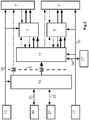
- the figure 1 represents a diagram of an example of an inverter 1 comprising three branches denoted B1, B2 and B3 respectively, mounted in parallel between a first connection point denoted C1 and a second connection point denoted C2.
- Each branch B1, B2 and B3 comprises a first switch 3 connected to the first connection point C1 mounted in series with a second switch 3 'connected to the second connection point C2.
- the first switches 3 are distributed over a high side of the inverter 1 denoted HS while the second switches 3 'are distributed over a low side of the inverter 1 denoted LS.
- the midpoints of the branches denoted R, S and T are connected to the phases of the electric motor to be supplied.
- the first connection point C1 is for example connected to a high potential of an energy source intended to supply energy to, or receive energy from, the electric motor via the inverter 1
- the second connection point C2 is for example connected to a low potential of this energy source.
- the inverter 1 will be a three-phase H-bridge inverter, however, the present invention is not limited to a three-phase H-bridge inverter but also extends to other multi-phase inverter structures. .
- the switches 3, 3 ' are here represented by transistors, for example insulated gate bipolar transistors ("Insulated Gate bipolar transistor (IGBT)” or metal-oxide gate field effect transistors (“Metal Oxide Semiconductor Field Effect Transistor (MOSFET) ”but the present invention is not limited to this type of transistors but extends to all types of switches.
- IGBT Insulated Gate bipolar transistor
- MOSFET Metal Oxide Semiconductor Field Effect Transistor
- the high HS and low LS sides of the inverter 1 also respectively comprise a first logic component 5 dedicated to driving the first switches 3 and a second logic component 5 'dedicated to driving the second switches 3'.
- These logic components 5 and 5 ′ are for example complex programmable logic circuits or networks (“Complex Programmable Logic Device (CPLD)” or integrated circuits with specific application (“Application Specific Integrated Circuit (ASIC)” in English). .
- CPLD Complex Programmable Logic Device
- ASIC Application Specific Integrated Circuit
- these logic components 5 and 5 ′ can also be microcontrollers or in-situ programmable gate arrays (“Field Programmable Gate Array (FPGA)”.
- the first logic component 5 can individually control the opening or closing of the first switches 3 while the second logic component 5 'can individually control the opening or closing of the second switches 3'.
- the first 5 and the second 5 ′ logic component only transmit the opening and closing commands respectively to the first 3 and to the second 3 ′ switches, coming for example from a control unit described later.
- the elements dedicated to controlling the high side switches HS are supplied by a first power source (not shown) while the elements dedicated to controlling the low side switches LS (second switches) are supplied by a second source d power supply (not shown) independent of the first power source.
- the second power source will correspond to this motor power supply battery, also called traction battery, for example.
- a high voltage battery greater than 100V for example
- the first power source will correspond to a second battery, for example an accessory power supply battery (12V for example).
- the use of the two logic components 5 and 5 'and of two independent power sources distributed on the high side HS and the low side LS of the inverter 1 makes it possible to be able to control at least the first 3 or the second 3 'switches in the event of a malfunction of one of the logic components 5 or 5' or of one of the power sources.
- Each switch 3 and 3 'of the inverter 1 is associated with a control unit ("driver" in English) denoted 7 for the first switches and 7' for the second switches, said control units 7 and 7 'being supplied respectively. by the first 15 and the second 17 power source.
- a potential barrier 9 can be placed at the level of the control units 7, 7 'which allows electrical insulation, in particular between the high voltage and low voltage masses, to reinforce the protection of people.
- the control units 7 and 7 ' are respectively connected to the first and to the second logic component 5 and 5'.
- the inverter 1 also comprises a processing unit 11 connected to the first and to the second logic component 5 and 5 'and intended to communicate with a control unit 13.
- the processing unit 11 and the control unit. control 13 are two distinct units, for example separated and linked by an electrical interface 12.
- the processing unit 11 is for example a logic component such as a network of programmable gates in-situ (“Field Programmable Gate Array (FPGA)” in English) or a microcontroller or microprocessor; and the control unit 13 can be a microcontroller or a microprocessor.
- the electrical interface 12 between the control unit 13 and the processing unit 11 is for example a serial peripheral interface (SPI) and may include a potential barrier 9 providing isolation. electric to strengthen user protection.
- SPI serial peripheral interface
- the use of a serial peripheral interface makes it possible to group together several types of signals and to reduce the number of isolators necessary to achieve the potential barrier 9.
- the processing 11 and control units 13 are both powered by the first 15 or the second 17 power supply.
- the processing unit 11 can be supplied by the first supply 15 and the control unit 13 by the second supply 17 or vice versa.
- the control unit 13 and the processing unit 11 are powered by the first power supply 15 which may be a battery accessory 15, for example a 12 volt battery.
- the first power supply 15 powers both the control unit 13, the processing unit 11 and the high side elements HS of the inverter 1 as well as sensors 27 of the inverter 1.
- a potential barrier 9 can be installed between the accessory battery 15 on the one hand and the elements of the high side HS and the sensors 27 of the inverter 1 on the other hand.
- the elements of the low side LS of the inverter 1 are supplied by the second power source 17, which may be the traction battery 17 of the electric motor of the vehicle.
- the two power sources 15 and 17 can be reversed.
- linear voltage regulators (“low dropout regulator (LDO)" 19 can be installed between the power sources 15 and 17 and the logic components 5 and 5 'so as to adapt the supply voltage. to the operating voltage of the logic components 5 and 5 ', for example 3V in the case of complex programmable logic circuits.
- LDO low dropout regulator
- an additional component 20 can be introduced between the traction battery 17 and the linear voltage regulator 19 to convert the high voltage supplied by the traction battery 17 into a voltage of 15 volts, the voltage of 15 volts being supplied to the linear voltage regulator 19.
- the inverter 1 also comprises comparators 21, three in the present case, the respective inputs of which are connected to the respective midpoints R, S and T, and the outputs of which are connected to the processing unit 11.
- the comparators 21 allow to compare an electrical quantity of the midpoints, generally the voltage, with a theoretical value which depends on the commands transmitted to the switches 3 and 3 '.
- the control unit 13 establishes a control plane for the switches 3 and 3 'as a function of the user's commands, for example the driver pressing the accelerator in the case of an electric vehicle; and / or operating parameters of the engine or of the vehicle measured by sensors, such as a position sensor of the rotor of the electric motor 23 or of operating parameters of the inverter 1 (such as for example the voltage of the DC bus, the intensity and phase of the current or the temperature of the elements ”) measured by sensors 27 and returned to the processing unit 11, generally via an analog / digital converter 22.
- An element 25 such as a system base chip (“System Basis Chip” in English) can also be used to supply the control unit 13 and the position sensor of the rotor 23 and allow monitoring (“watchdog” in English). English) and a reset of these elements.
- System Basis Chip System Basis Chip
- the control plane corresponds, for example, to the instants of opening and closing of switches 3 and 3 'established by pulse width modulation (MLI or "Pulse Width Modulation (PWM) ”in English).
- MMI pulse width modulation
- PWM Pulse Width Modulation
- These commands are transmitted by the control unit 13 to the processing unit 11 which also takes into account the operating parameters of the inverter 1 returned by the various sensors such as for example the DC voltage value of the bus, the intensity and phase of the current supplied by the bus ....
- the processing unit 11 can then for example introduce or eliminate dead times at the level of the modulation commands or only transmit the commands without modifying them.
- the processing unit 11 transmits these commands to the control units 7 and 7 'via the logic components 5 and 5'.
- the control units 7 and 7 'then control the opening and closing of the various switches 3 and 3'.
- the voltage value at the midpoint (R, S and T) varies.
- the comparators 21 make it possible to compare the voltage value measured at the level of the midpoint R, S or T with an expected voltage value which is a function of the commands transmitted by the processing unit 11 or the control unit 13.
- the processing unit 11 detects this malfunction thanks to the comparators 21.
- the comparators 21 also allow the processing unit 11 to detect a malfunction of a logic component 5 or 5 'since in the event of a malfunction of a logic component 5 or 5 ', the commands coming from the processing unit 11 are not transmitted correctly by the logic components 5 and 5' and the associated switches 3 or 3 'will not be controlled in accordance with the commands transmitted by the processing unit 11.
- Signals of controls exchanged between the processing unit 11 and the logic components 5 and 5 ' can also be used by the processing unit 11 to detect a malfunction of a logic component 5, 5'.
- the processing unit 11 can detect a failure of the control unit 13 thanks to control signals transmitted by the control unit 13, for example if the control unit 13 sends an error signal. to the processing unit 11 or by means of watchdog type monitoring signals.
- the logic components 5 and 5 ' can detect a malfunction of the processing unit 11 thanks to control signals coming from the processing unit, for example if they receive error signals coming from the processing unit 11 or detect an anomaly in the “watchdog” type control signals.
- the figure 3 shows a first embodiment corresponding to the architecture of the figure 2 .
- the arrows 31 and 33 respectively connect the first 15 and the second 17 feeds to the elements which they feed.
- the first power supply 15 feeds the control unit 13, the processing unit 11, the elements (5, 7) of the high side HS while the second power supply 17 feeds the elements (5 ', 7') of the low side LS .
- the control unit 13 is connected on the one hand to processing elements 30 of the vehicle, for example via a serial communication bus (also called “controller area network (CAN)” in English) 35 and on the other hand to sensors 27 of the vehicle or of the inverter 1 via a connection 32.
- CAN controller area network
- the control signals are represented by solid arrows and correspond to the modulation signals for the arrows 37 and to the clock signals for the arrows 39.
- the dotted arrows represent control signals and are of three types: arrows 41 in regular dotted lines correspond to error signals or fault signals, arrows 43 with a two-dot pattern and a line which correspond to monitoring signals (or "watchdog" signals in English) and the arrows 45 with a two-point and three-line pattern which correspond to the permission signals (or “enable” signals in English).
- the error signals 41 are sent when an anomaly is detected by an element while the monitoring signals 43 are sent continuously so that an absence of a monitoring signal or an abnormal signal can be interpreted as an error. dysfunction.
- the permission signals 45 make it possible to activate or deactivate an element, in particular to control an element so that it operates normally or in an alternative mode.
- the permission signals 45 are sent by the control unit 13 and the processing unit 11 to respectively the control units 7 'on the low side LS and the control units 7 on the high side HS so that when these permission signals 45 are at level 1, the driving units 7, 7 'drive the switches 3 and 3' according to the control signals received from the logic components 5 and 5 'and when the permission signals are at the level 0, the control units 7, 7 'are inhibited and no longer control the switches 3 and 3' which then remain open (the commands associated with level 0 and level 1 can obviously be reversed).
- the permission signal 45 takes a high impedance value. In the case of the present invention, this high impedance signal is interpreted as a signal at level 1, by example using a pull-up resistor or pull-up resistor at the control units 7, 7 '.
- this procedure aims to short-circuit, that is to say to close, the switches 3 on the high side HS of the inverter 1 while the other switches, on the low side LS , remain open, or to short-circuit the switches 3 'on the low side LS of the inverter 1 while the other switches, on the high side HS, remain open, so as to obtain a motor, and therefore a vehicle, coasting.
- the user can then use the mechanical brakes to immobilize the vehicle. This procedure helps prevent the vehicle from stopping suddenly.
- the various malfunctions, their detection mode and the commands implemented in the event of a malfunction being detected will now be described, for the configuration of the power supply and control circuit of the inverter of the unit. figure 3 from the summary table of the figure 4 .
- the first column of the table indicates the various malfunctions that can be encountered in inverter 1.
- the second column indicates the element of inverter 1 which detects the malfunction.
- the third column indicates the action generated in response to the malfunction, this action being initiated by the element that detected the malfunction indicated in the second column.
- the first type of malfunction corresponds to a malfunction of a switch 3, a control unit 7 or a logic component 5 on the high side HS.
- This malfunction is detected by the processing unit 11 via the comparators 21 or via the control signals, such as for example the error signals 41 returned by the first logic component 5 or the supervision signals 43 returned by the first logic component. 5 in the event of a malfunction of the first logic component 5.
- the detection of a malfunction can also correspond to the absence of reception of control signals. If the malfunction or failure causes a short-circuit of at least one of the switches 3 on the high side HS, which can be detected via the comparators 21, the processing unit 11 commands the closing of all the switches 3 of the high side HS and the opening of the switches 3 'on the low side LS.
- the processing unit 11 can indicate to the control unit 13 the malfunction via the error signals 41.
- the control unit 13 can then inhibit the control units 7 'on the low side LS via permission signals 45 to open switches 3 '. Otherwise, the processing unit 11 controls the closing of the switches 3 'on the low side LS via the second logic component 5'.
- the processing unit 11 inhibits the control units 7 on the high side HS via the permission signals 45.
- the first switches 3 are found in the open position while the second switches 3 'are found in short-circuit which results in the freewheeling of the vehicle.
- the second type of malfunction corresponds to a malfunction of a switch 3 ', a control unit 7' or a logic component 5 'on the low side LS of inverter 1. This malfunction is detected by the unit. processing 11 via the comparators 21 or via the control signals, such as for example the error signals 41 returned by the second logic component 5 'or the monitoring signals 43 returned by the second logic component 5' in the event of a malfunction of the second logic component 5 '. If the malfunction or failure leads to a short-circuit of at least one of the switches 3 'on the low side LS, which can be detected via the comparators 21, the processing unit 11 commands the closing of all the switches 3. 'on the low side LS and the opening of the switches 3 on the high side HS.
- the processing unit 11 can inhibit the control units 7 on the high side HS via the permission signals 45 to open the switches 3. Otherwise, the processing unit 11 controls the closing of the first switches 3 via the first logic component 5. The processing unit 11 indicates to the control unit 13 the malfunction via the error signals 41. The control unit command 13 then inhibits the pilot units 7 'on the low side LS via the permission signals 45. Thus, the first switches 3 are found in short-circuit while the second switches 3' are found open which causes the wheeling. free from the vehicle.
- the third type of malfunction corresponds to a malfunction of the control unit 13.
- This malfunction is detected by the processing unit 11 via the control signals sent by the control unit 13, that is to say either the error signals 41, or the monitoring signals 43 transmitted to the processing unit 11.
- the malfunction can also be detected by the control unit 13 itself by a self-diagnosis or by a component 25 dedicated to monitoring such as for example a basic chip (“System Basis Chip”).
- the processing unit 11 then controls the closing of the first switches 3 via the logic component 5 and controls the opening of the second switches 3 'via the second logic component 5'. If the control unit malfunctions 13 causes the permission signals 45 to go to 0, the second switches 3 'are also in the open position.
- the fourth type of malfunction corresponds to a malfunction of the processing unit 11. This malfunction is detected by the logic components 5 and 5 'thanks to the monitoring signals 43 and / or by the control unit 13 thanks to the monitoring signals. 43 or to error signals 41.
- the second logic component 5 'then controls the closing of the second switches 3' while the first logic component 5 controls the opening of the first switches 3.
- the first switches 3 are also found in the open position.
- the fifth type of malfunction corresponds to a malfunction of the first power supply 15. This malfunction is detected by the second logic component 5 'since the elements of the high side HS of the inverter 1, the control unit 11 and the control unit. treatment 13 are no longer supplied.
- the second logic component 5 'then controls the closing of the second switches 3'. As the control units 7 on the high side HS are not supplied with power, the first switches 3 are in the open position.
- the sixth type of malfunction corresponds to a malfunction of the second power supply 17. This malfunction is detected by the processing unit 11 via the comparators 21 or via the monitoring signals 43 returned (or not returned) by the second logic component 5 ′ . The processing unit 11 then controls the closing of the first switches 3 via the first logic component 5 and indicates the malfunction to the control unit 13 via the error signals 41.
- the configuration of the figure 3 enables the vehicle to be coasted when a malfunction appears on one of the components of the power supply and control circuit of inverter 1.
- the driver can immobilize the vehicle using the mechanical brake of the vehicle.
- the figure 5 shows a second configuration of the supply and control circuit of the inverter 1 in which the control unit 13 and the processing unit 11 are supplied by two different power sources.
- a barrier of potential 9 is placed between the control unit 13 and the processing unit 11.
- This potential barrier 9 eliminates the need for the potential barrier 9 located at the level of the control units 7, 7 '.
- a positioning of the potential barriers 9 as in the example illustrated in figure 3 is also possible.
- the signals exchanged between the control unit 13 and the processing unit 11 are the same as in the embodiment of the figure 3 but are grouped together in a serial peripheral interface type link so as to reduce the number of insulators necessary to achieve the potential barrier 9.
- the first power supply 15 feeds the control unit 13 and the components 5, 7 from the high side HS while the second power supply 17 feeds the processing unit 11 and the components 5 'and 7' from the low side LS.
- the control unit 13 is connected on the one hand to processing elements 30 of the vehicle, for example via a serial communication bus (also called “controller area network (CAN)” in English) 35 and on the other hand to sensors 27 of the vehicle or of the inverter 1 via a connection 32. Sensors 27 ′ can also be connected to the processing unit 11 via a connection 34.
- the control signals exchanged between the various elements of the supply circuit are the same as for the embodiment of the figure 3 .
- the first type of malfunction corresponds to a malfunction of a switch 3, a control unit 7 or a logic component 5 on the high side HS.
- This malfunction is detected by the processing unit 11 via the comparators 21 or via the control signals, such as for example the error signals 41 returned by the first logic component 5 or via the monitoring signals 43 returned by the first component logic 5 in the event of a malfunction of the first logic component 5.
- the processing unit 11 commands the closing of all the switches 3 of the high side HS and the opening of the switches 3 'on the low side LS.
- the processing unit 11 can inhibit the drive units 7 'of the low side LS via the permission signals 45 to open the switches 3'. Otherwise, the processing unit 11 controls the closing of the second switches 3 'via the second logic component 5' and indicates to the control unit 13 the malfunction via the error signals 41. The control unit 13 then inhibits the control units 7 on the high side HS via the permission signals 45 so as to put the first switches 3 in the open position. Thus, the first switches 3 are found in the open position while the second switches 3 'are found in a short circuit, which causes the vehicle to freewheel.
- the second type of malfunction corresponds to a malfunction of a switch 3 ', a control unit 7' or a logic component 5 'on the low side LS of inverter 1. This malfunction is detected by the unit. processing 11 via the comparators 21 or via the error signals 41 returned by the second logic component 5 'or via the control signals, such as for example the monitoring signals 43 returned by the second logic component 5' in the event of a malfunction of the second logic component 5 '. If the malfunction or failure leads to a short-circuit of at least one of the switches 3 'on the low side LS, which can be detected via the comparators 21, the processing unit 11 commands the closing of all the switches 3. 'on the low side LS and the opening of the switches 3 on the high side HS.
- the processing unit 11 can indicate to the control unit 13 the malfunction via the error signals 41.
- the control unit 13 can then inhibit the control units 7 on the high side HS via the signals permission 45 to open the switches 3. Otherwise, the processing unit 11 controls the closing of the first switches 3 via the first logic component 5.
- the processing unit 11 inhibits the control units 7 'on the low side LS via the permission signals 45.
- the first switches 3 are found in short circuit while the second switches 3 'are found open, which causes the vehicle to freewheel.
- the third type of malfunction corresponds to a malfunction of the control unit 13.
- This malfunction is detected by the processing unit 11 via the control signals sent by the control unit 13, that is to say either the error signals 41, that is to say the monitoring signals 43 transmitted to the processing unit 11.
- the malfunction can also be detected by the control unit 13 itself by a self-diagnosis or by a component 25 dedicated to monitoring such as a basic chip.
- the processing unit 11 then controls the opening of the first switches 3 via the first logic component 5 and the closing of the second switches 3 'via the second logic component 5'. If the malfunction of the control unit 13 causes the permission signals 45 to go to 0, the first switches 3 are also found to be open.
- the fourth type of malfunction is a malfunction of the unit. processing 11. This malfunction is detected by the logic components 5 and 5 'on the high side HS and on the low side LS thanks to the monitoring signals 43 as well as by the control unit 13 thanks to the monitoring signals 43 or the signals d. 'error 41.
- the second logic component 5' then controls the opening of the second switches 3 '.
- the first logic component 5 controls the closing of the first switches 3. If the malfunction of the processing unit 11 causes the permission signals 45 to go to 0, the second switches 3 'are also found open.
- the fifth type of malfunction corresponds to a malfunction of the first power supply 15. This malfunction is detected by the processing unit 11 via the comparators 21 or the error 41 or monitoring signals 43 originating from the first logic component 5 or from the 'control unit 13. The control unit 11 then controls the closing of the second switches 3' via the second logic component 5 ', the first switches 3 being open due to the absence of power supply to the components 3, 5, 7 on the high side HS.
- the sixth type of malfunction corresponds to a malfunction of the second power supply 17. This malfunction is detected by the first logic component 5 and / or by the control unit 13 via the absence of monitoring signals 43 from the control unit. processing 11. The first logic component 5 then controls the closing of the first switches 3, the second switches 3 'being open due to the absence of power supply to the components 3', 5 'and 7' on the low side LS.
- the configuration of the figure 5 also enables the vehicle to be coasted when a malfunction appears on one of the components of the power supply circuit of inverter 1.
- the driver can immobilize the vehicle by using the brake vehicle mechanics.
- the use of the logic components 5 and 5 'combined with the use of the two independent power sources 15 and 17 respectively for the high side HS and the low side LS of the inverter 1 therefore allow on the one hand a detection of 'a malfunction of an element of the inverter 1 and on the other hand to short-circuit the first switches 3 located on the high side HS or the second switches 3' located on the low side LS of the inverter 1.
- the Proposed embodiments also make it possible to put the other switches 3 or 3 'in the open position so as to obtain an electric motor with a first side of which the switches 3, 3 'are open and a second side whose switches 3', 3 are short-circuited and therefore a freewheeling vehicle which allows the driver to be able to manage the vehicle deceleration himself using the mechanical brake and therefore makes it possible to avoid sudden braking in the middle of a fast lane for example.
- Such a configuration of the inverter 1 makes it possible to ensure the safety of the users following a malfunction of one of the elements of the inverter 1 without this requiring numerous additional equipment which entails
Description
La présente invention concerne le domaine des onduleurs et notamment les onduleurs de puissance utilisés dans les véhicules automobiles.The present invention relates to the field of inverters and in particular to power inverters used in motor vehicles.
Ces onduleurs sont utilisés dans les véhicules électriques ou hybrides pour convertir le courant continu fourni par des batteries, généralement haute tension, en courant alternatif permettant d'alimenter le moteur électrique.These inverters are used in electric or hybrid vehicles to convert the direct current supplied by batteries, generally high voltage, into alternating current to power the electric motor.
L'un des points essentiels pour la mise au point des moteurs électriques destinés à équiper un véhicule automobile concerne la sécurité des passagers comme des personnes se trouvant à proximité du véhicule. Ainsi, en cas de dysfonctionnement ou panne d'un élément lié à l'électronique de commande et notamment à l'onduleur du moteur électrique qui est directement lié aux roues et à la propulsion du véhicule, une configuration de repli ou de secours doit être mise en œuvre pour éviter un accident.One of the essential points for the development of electric motors intended for equipping a motor vehicle concerns the safety of passengers and of persons in the vicinity of the vehicle. Thus, in the event of a malfunction or failure of an element linked to the control electronics and in particular to the inverter of the electric motor which is directly linked to the wheels and to the propulsion of the vehicle, a fallback or emergency configuration must be implemented to avoid an accident.
Un moyen envisageable pour éviter un accident consiste à établir une position de secours des transistors de l'onduleur dans laquelle ils se mettraient en position ouverte. Si la force électromotrice redressée créée par les aimants du rotor de la machine est supérieure à la tension du bus continu, généralement la batterie, alors une telle position crée un couple résistant qui freine le véhicule. Ainsi, en cas de dysfonctionnement à haute vitesse, par exemple sur autoroute, le véhicule freinerait brusquement, ce qui peut être très dangereux.One possible way to avoid an accident consists in establishing a backup position for the inverter transistors in which they would go into the open position. If the rectified electromotive force created by the machine rotor magnets is greater than the voltage of the DC bus, usually the battery, then such a position creates a resistive torque which brakes the vehicle. Thus, in the event of a malfunction at high speed, for example on a motorway, the vehicle would brake suddenly, which can be very dangerous.
Une autre solution consiste à doubler certains éléments liés à l'électronique de commande et à utiliser des fonctions logiques « OU » pour générer une commande dans le cas d'un dysfonctionnement d'un des deux éléments. Cependant, en cas de surtension de l'alimentation, il pourrait y avoir une défaillance de la fonction « OU ». De plus, le doublement des éléments liés à l'électronique de commande entraîne un coût supplémentaire et peut poser des problèmes de synchronisation si deux éléments doivent envoyer un message simultanément suite à un dysfonctionnement.Another solution consists in doubling certain elements linked to the control electronics and in using “OR” logic functions to generate a command in the event of a malfunction of one of the two elements. However, in the event of a power surge, there could be a failure of the “OR” function. In addition, the doubling of the elements linked to the control electronics entails an additional cost and can pose synchronization problems if two elements have to send a message simultaneously following a malfunction.
Il convient donc de trouver une solution permettant d'assurer la sécurité des utilisateurs et personnes à proximité du véhicule en cas de dysfonctionnement ou de panne de l'un des éléments de l'onduleur.A solution must therefore be found to ensure the safety of users and people near the vehicle in the event of a malfunction or failure of one of the elements of the inverter.
Le document
Pour pallier ces inconvénients, la présente invention a donc pour objet un onduleur conforme à la revendication 1 et un procédé conforme à la revendication 19.To overcome these drawbacks, the subject of the present invention is therefore an inverter according to claim 1 and a method according to
L'utilisation de deux sources d'alimentation pour alimenter indépendamment le côté haut et le côté bas de l'onduleur combiné à l'utilisation de deux composants logiques placés respectivement du côté haut et du côté bas permet de pouvoir mettre en court-circuit les interrupteurs du côté haut ou du côté bas de l'onduleur en cas de dysfonctionnement de l'un des éléments de l'onduleur. La mise en court-circuit des interrupteurs d'un côté de l'onduleur permettant de contrôler la force électromotrice créée par les aimants du rotor et ainsi de mettre le moteur électrique et donc le véhicule en roue libre.The use of two power sources to independently power the high side and the low side of the inverter combined with the use of two logic components placed respectively on the high side and the low side allows to be able to short-circuit the switches on the high or low side of the inverter in the event of a malfunction of one of the inverter elements. The short-circuiting of the switches on one side of the inverter makes it possible to control the electromotive force created by the magnets of the rotor and thus to put the electric motor and therefore the vehicle in freewheel.
En particulier, la mise en court-circuit des premiers interrupteurs correspond à une fermeture des premiers interrupteurs et une ouverture des deuxièmes interrupteurs ; et la mise en court-circuit des deuxièmes interrupteurs correspond à une fermeture des deuxièmes interrupteurs et une ouverture des premiers interrupteurs.In particular, the short-circuiting of the first switches corresponds to a closing of the first switches and an opening of the second switches; and the short-circuiting of the second switches corresponds to a closing of the second switches and an opening of the first switches.
Selon un mode de réalisation de la présente invention, l'onduleur comprend également une unité de traitement destinée à communiquer d'une part avec une unité de commande et d'autre part avec le premier et le deuxième composant logique.According to one embodiment of the present invention, the inverter also comprises a processing unit intended to communicate on the one hand with a control unit and on the other hand with the first and the second logic component.
Selon un mode de réalisation, l'unité de traitement est configurée pour détecter un dysfonctionnement d'un élément du côté haut ou du côté bas.According to one embodiment, the processing unit is configured to detect a malfunction of an element of the high side or the low side.
Selon un mode de réalisation de la présente invention, l'onduleur comprend également une pluralité de comparateurs dont les entrées sont reliées respectivement aux points milieux des branches et dont les sorties sont reliées à l'unité de traitement, les comparateurs étant configurés pour comparer une grandeur électrique de leur point milieu respectif à une valeur qui est fonction de la configuration des interrupteurs, l'unité de traitement étant configurée pour détecter un dysfonctionnement d'un élément du côté haut ou du côté bas à partir d'un écart entre ladite grandeur électrique et ladite valeur.According to an embodiment of the present invention, the inverter also comprises a plurality of comparators whose inputs are connected respectively to the midpoints of the branches and whose outputs are connected to the processing unit, the comparators being configured to compare a electrical quantity from their respective midpoint to a value which depends on the configuration of the switches, the processing unit being configured to detect a malfunction of an element on the high side or on the low side from a difference between said quantity electrical and said value.
Selon un mode de réalisation, l'unité de traitement est configurée pour détecter un dysfonctionnement d'un élément du côté haut, respectivement d'un élément du côté bas, à partir de signaux de contrôle envoyés par ledit composant logique du côté haut, respectivement par ledit composant logique du côté bas.According to one embodiment, the processing unit is configured to detect a malfunction of an element on the high side, respectively of an element on the low side, from control signals sent by said logic component on the high side, respectively by said logic component on the low side.
Selon un mode de réalisation, les composants logiques du côté haut et/ou du côté bas sont configurés pour détecter un dysfonctionnement de l'unité de traitement à partir de signaux de contrôle envoyés par ladite unité de traitement.According to one embodiment, the logic components on the high side and / or on the low side are configured to detect a malfunction of the processing unit from control signals sent by said processing unit.
Selon un mode de réalisation, l'unité de traitement est configurée pour commander la mise en court-circuit des premiers ou deuxièmes interrupteurs en fonction d'un dysfonctionnement d'un élément du côté haut ou du côté bas.According to one embodiment, the processing unit is configured to control the short-circuiting of the first or second switches as a function of a malfunction of an element on the high side or on the low side.
Selon un mode de réalisation, les composants logiques du côté bas et du côté haut sont configurés pour commander la mise en court-circuit des deuxièmes, respectivement des premiers, interrupteurs en cas de dysfonctionnement de l'unité de traitement.According to one embodiment, the logic components on the low side and on the high side are configured to control the short-circuiting of the second, respectively of the first, switches in the event of a malfunction of the processing unit.
Selon un mode de réalisation, l'unité de commande est comprise dans l'onduleur.According to one embodiment, the control unit is included in the inverter.
Selon un mode de réalisation, l'unité de commande est configurée pour détecter un dysfonctionnement de l'unité de traitement, et/ou l'unité de traitement est configurée pour détecter un dysfonctionnement de l'unité de commande.According to one embodiment, the control unit is configured to detect a malfunction of the processing unit, and / or the processing unit is configured to detect a malfunction of the control unit.
Ainsi, la sécurité de l'onduleur en cas de défaillance est renforcée.In this way, the safety of the inverter in the event of a failure is enhanced.
Selon un mode de réalisation, l'unité de commande est configurée pour détecter un dysfonctionnement de l'unité de traitement à partir de signaux de contrôle envoyés par ladite unité de traitement, et/ou l'unité de traitement est configurée pour détecter un dysfonctionnement de l'unité de commande à partir de signaux de contrôle envoyés par ladite unité de commande.According to one embodiment, the control unit is configured to detect a malfunction of the processing unit from control signals sent by said processing unit, and / or the processing unit is configured to detect a malfunction. of the control unit from control signals sent by said control unit.
Selon un mode de réalisation, l'unité de traitement ou l'unité de commande sont configurées pour commander la mise en court-circuit des deuxièmes, ou des premiers, interrupteurs en cas d'un dysfonctionnement.According to one embodiment, the processing unit or the control unit are configured to control the short-circuiting of the second, or the first, switches in the event of a malfunction.
Selon un mode de réalisation, l'unité de commande ou l'unité de traitement sont configurées pour commander la mise en court-circuit des premiers ou deuxièmes interrupteurs par l'intermédiaire de signaux de permission permettant d'activer ou désactiver les premiers ou deuxièmes interrupteurs.According to one embodiment, the control unit or the processing unit are configured to control the short-circuiting of the first or second switches by means of permission signals making it possible to activate or deactivate the first or second. switches.
Selon un mode de réalisation, l'unité de commande est configurée pour envoyer des signaux de permission vers le côté haut permettant d'activer ou désactiver les interrupteurs du côté haut, et l'unité de traitement est configurée pour envoyer des signaux de permission vers le côté bas permettant d'activer ou désactiver les interrupteurs du côté bas; ou l'unité de commande est configurée pour envoyer des signaux de permission vers le côté bas permettant d'activer ou désactiver les interrupteurs du côté bas, et l'unité de traitement est configurée pour envoyer des signaux de permission vers le côté haut permettant d'activer ou désactiver les interrupteurs du côté haut.According to one embodiment, the control unit is configured to send permission signals to the high side to enable or disable the switches on the high side, and the processing unit is configured to send permission signals to the high side. the low side to activate or deactivate the switches on the low side; or the control unit is configured to send permission signals to the low side to enable or disable the low side switches, and the processing unit is configured to send permission signals to the high side to enable '' activate or deactivate the switches on the high side.
Selon un mode de réalisation, l'unité de traitement est un élément distinct de l'unité de commande.According to one embodiment, the processing unit is a separate element from the control unit.
Selon un mode de réalisation, l'onduleur est configuré pour alimenter un moteur électrique de véhicule automobile à partir de la première source d'alimentation ou de la deuxième source d'alimentation.According to one embodiment, the inverter is configured to supply an electric motor of a motor vehicle from the first power source or from the second power source.
Selon un mode de réalisation, le côté haut comprend des premières unités de pilotage, le côté bas comprend des deuxièmes unités de pilotage, les premiers et les deuxièmes interrupteurs étant pilotés respectivement via les premières et les deuxièmes unités de pilotage.According to one embodiment, the high side comprises first control units, the low side comprises second control units, the first and second switches being controlled respectively via the first and the second control units.
Selon un mode de réalisation, les signaux de contrôle sont des signaux de surveillance ou des signaux d'erreur.According to one embodiment, the control signals are monitoring signals or error signals.
Selon un mode de réalisation, l'unité de traitement et l'unité de commande sont toutes les deux alimentées par la première, respectivement la deuxième, source d'alimentation.According to one embodiment, the processing unit and the control unit are both powered by the first, respectively the second, power source.
Selon un mode de réalisation, l'unité de traitement est alimentée par la première, respectivement la deuxième, source d'alimentation ; et l'unité de commande est alimentée par la deuxième, respectivement la première, source d'alimentation.According to one embodiment, the processing unit is supplied by the first, respectively the second, power source; and the control unit is powered by the second, respectively the first, power source.
La présente invention concerne également un procédé de commande d'un onduleur selon la revendication 19 dans lequel en cas de dysfonctionnement de l'unité de traitement, le premier composant logique, respectivement le deuxième composant logique, détecte ledit dysfonctionnement de l'unité de traitement à partir des signaux de contrôle envoyés par ladite unité de traitement et commande la mise en court-circuit des premiers, respectivement des deuxièmes, interrupteurs.The present invention also relates to a method for controlling an inverter according to
La présente invention concerne aussi un procédé de commande d'un onduleur selon l'invention dans lequel, en cas de dysfonctionnement d'un élément du côté haut ou d'un élément du côté bas, l'unité de traitement détecte ledit dysfonctionnement et commande la mise en court-circuit des premiers interrupteurs ou des deuxièmes interrupteurs en fonction du type de dysfonctionnement.The present invention also relates to a method for controlling an inverter according to the invention in which, in the event of a malfunction of an element on the high side or of an element on the low side, the processing unit detects said malfunction and controls short-circuiting the first switches or the second switches depending on the type of malfunction.
La présente invention concerne en outre un procédé de commande d'un onduleur selon l'invention dans lequel, en cas de dysfonctionnement de l'unité de commande, l'unité de traitement détecte ledit dysfonctionnement de l'unité de commande à partir des signaux de contrôle envoyés par l'unité de commande et commande la mise en court-circuit des premiers ou des deuxièmes interrupteurs.The present invention further relates to a method for controlling an inverter according to the invention in which, in the event of a malfunction of the control unit, the processing unit detects said malfunction of the control unit from the signals. signals sent by the control unit and commands the short-circuiting of the first or second switches.
La présente invention concerne également un procédé de commande d'un onduleur selon l'invention dans lequel, l'unité de traitement et l'unité de commande sont alimentées toutes les deux par la première, respectivement la deuxième, source d'alimentation et dans lequel en cas de dysfonctionnement de la première, respectivement de la deuxième, source d'alimentation, le deuxième, respectivement le premier, composant logique commande la mise en court-circuit des deuxièmes, respectivement des premiers, interrupteurs.The present invention also relates to a method of controlling an inverter according to the invention in which the processing unit and the control unit are both supplied by the first, respectively the second, power source and in which in the event of a malfunction of the first, respectively of the second, power source, the second, respectively the first, logic component controls the short-circuiting of the second, respectively of the first, switches.
La présente invention concerne aussi un procédé de commande d'un onduleur selon l'invention dans lequel, l'unité de traitement est alimentée par la première, respectivement la deuxième, source d'alimentation, et l'unité de commande est alimentée par la deuxième, respectivement la première source d'alimentation ; et en cas de dysfonctionnement de la source d'alimentation alimentant l'unité de commande, l'unité de traitement commande la mise en court-circuit des interrupteurs alimentés par sa source d'alimentation ; et en cas de dysfonctionnement de la source d'alimentation alimentant l'unité de traitement, le composant logique alimenté par l'autre source d'alimentation commande la mise en court-circuit des interrupteurs alimentés par cette autre source d'alimentation.The present invention also relates to a method for controlling an inverter according to the invention in which the processing unit is powered by the first, respectively the second, power source, and the control unit is powered by the second, respectively the first power source; and in the event of a malfunction of the power source supplying the control unit, the processing unit controls the short-circuiting of the switches supplied by its power source; and in the event of a malfunction of the power source supplying the processing unit, the logic component supplied by the other supply source controls the short-circuiting of the switches supplied by this other supply source.
D'autres caractéristiques et avantages de l'invention apparaîtront dans la description qui va maintenant en être faite, en référence aux dessins annexés qui en représentent, à titre indicatif mais non limitatif, un mode de réalisation possible.Other characteristics and advantages of the invention will appear in the description which will now be given, with reference to the appended drawings which represent, by way of indication but not limitation, a possible embodiment.
Sur ces dessins :
- la
figure 1 représente un schéma d'un onduleur triphasé ; - la
figure 2 représente un schéma d'une architecture d'un circuit d'alimentation et de commande d'un onduleur triphasé selon un mode de réalisation de la présente invention ; - la
figure 3 représente un schéma des signaux échangés entre les différents éléments du circuit d'alimentation et de commande d'un onduleur selon une première configuration du circuit d'alimentation ; - la
figure 4 représente un tableau des différents dysfonctionnements du circuit d'alimentation et de commande de l'onduleur, de leur mode de détection et de l'action engagée lorsque ces dysfonctionnements sont détectés dans le cas de la première configuration ; - la
figure 5 représente un schéma des signaux échangés entre les différents du circuit d'alimentation et de commande d'un onduleur selon une deuxième configuration du circuit d'alimentation ; - la
figure 6 représente un tableau des différents dysfonctionnements du circuit d'alimentation et de commande de l'onduleur, de leur mode de détection et de l'action engagée lorsque ces dysfonctionnements sont détectés dans le cas de la deuxième configuration.
- the
figure 1 represents a diagram of a three-phase inverter; - the
figure 2 represents a diagram of an architecture of a supply and control circuit of a three-phase inverter according to an embodiment of the present invention; - the
figure 3 represents a diagram of the signals exchanged between the different elements of the supply and control circuit of an inverter according to a first configuration of the supply circuit; - the
figure 4 represents a table of the various malfunctions of the power supply and control circuit of the inverter, their detection mode and the action taken when these malfunctions are detected in the case of the first configuration; - the
figure 5 represents a diagram of the signals exchanged between the different ones of the supply and control circuit of an inverter according to a second configuration of the supply circuit; - the
figure 6 represents a table of the various malfunctions of the power supply and control circuit of the inverter, their detection mode and the action taken when these malfunctions are detected in the case of the second configuration.
Sur ces figures, les mêmes numéros de référence désignent des éléments identiques.In these figures, the same reference numbers designate identical elements.
La présente invention concerne un onduleur et le procédé de commande associé. La
Le premier point de connexion C1 est par exemple relié à un potentiel haut d'une source d'énergie destinée à fournir de l'énergie à, ou recevoir de l'énergie depuis, le moteur électrique par l'intermédiaire de l'onduleur 1. Le deuxième point de connexion C2 est par exemple relié à un potentiel bas de cette source d'énergie.The first connection point C1 is for example connected to a high potential of an energy source intended to supply energy to, or receive energy from, the electric motor via the inverter 1 The second connection point C2 is for example connected to a low potential of this energy source.
Dans la suite de la description, l'onduleur 1 sera un onduleur triphasé à pont en H cependant, la présente invention ne se limite pas à un onduleur triphasé à pont en H mais s'étend aussi à d'autres structures d'onduleur multiphasé.In the remainder of the description, the inverter 1 will be a three-phase H-bridge inverter, however, the present invention is not limited to a three-phase H-bridge inverter but also extends to other multi-phase inverter structures. .
Les interrupteurs 3, 3' sont ici représentés par des transistors, par exemple des transistors bipolaires à grille isolée (« Insulated Gate bipolar transistor (IGBT) » en anglais) ou des transistors à effet de champ à grille métal-oxyde (« Metal Oxide Semiconductor Field Effect Transistor (MOSFET) » en anglais) mais la présente invention ne se limite pas à ce type de transistors mais s'étend à tous types d'interrupteurs.The
Les côtés haut HS et bas LS de l'onduleur 1 comprennent également respectivement un premier composant logique 5 dédié au pilotage des premiers interrupteurs 3 et un deuxième composant logique 5' dédié au pilotage des deuxièmes interrupteurs 3'. Ces composants logiques 5 et 5' sont par exemple des circuits ou réseaux logiques programmables complexes (« Complex Programmable Logic Device (CPLD) » en anglais) ou des circuits intégrés à application spécifique (« Application Specific Integrated Circuit (ASIC) » en anglais). Alternativement, ces composants logiques 5 et 5' peuvent également être des microcontrôleurs ou des réseaux de portes programmables in-situ (« Field Programmable Gate Array (FPGA) » en anglais). Le premier composant logique 5 peut commander individuellement l'ouverture ou la fermeture des premiers interrupteurs 3 tandis que le deuxième composant logique 5' peut commander individuellement l'ouverture ou la fermeture des deuxièmes interrupteurs 3'. Cependant, en fonctionnement normal, le premier 5 et le deuxième 5' composant logique ne font que transmettre les commandes d'ouverture et de fermeture respectivement aux premiers 3 et aux deuxièmes 3' interrupteurs, provenant par exemple d'une unité de commande décrite ultérieurement. Les éléments dédiés au pilotage des interrupteurs côté haut HS (premiers interrupteurs) sont alimentés par une première source d'alimentation (non représentée) tandis que les éléments dédiés au pilotage des interrupteurs côté bas LS (deuxièmes interrupteurs) sont alimentés par une deuxième source d'alimentation (non représentée) indépendante de la première source d'alimentation. Par exemple, dans le cas d'un onduleur situé dans un véhicule automobile électrique dont le moteur électrique est alimenté par une batterie, la deuxième source d'alimentation correspondra à cette batterie d'alimentation du moteur, aussi appelée batterie de traction, par exemple une batterie haute tension (supérieure à 100V par exemple) tandis que la première source d'alimentation correspondra à une deuxième batterie, par exemple une batterie d'alimentation des accessoires (12V par exemple).The high HS and low LS sides of the inverter 1 also respectively comprise a
Ainsi, l'utilisation des deux composants logiques 5 et 5' et de deux sources d'alimentation indépendantes répartis sur le côté haut HS et le côté bas LS de l'onduleur 1 permet de pouvoir contrôler au moins les premiers 3 ou les deuxièmes 3' interrupteurs en cas de dysfonctionnement de l'un des composants logiques 5 ou 5' ou de l'une des sources d'alimentation.Thus, the use of the two
Une architecture du circuit électronique de commande d'onduleur triphasé va maintenant être décrite en détails à partir de la
L'onduleur 1 comprend également une unité de traitement 11 reliée au premier et au deuxième composant logique 5 et 5' et destinée à communiquer avec une unité de commande 13. Dans le cas présent, l'unité de traitement 11 et l'unité de commande 13 sont deux unités distinctes, par exemple séparées et reliées par une interface électrique 12. L'unité de traitement 11 est par exemple un composant logique comme un réseau de portes programmables in-situ (« Field Programmable Gate Array (FPGA) » en anglais) ou un microcontrôleur ou un microprocesseur ; et l'unité de commande 13 peut être un microcontrôleur ou microprocesseur. L'interface électrique 12 entre l'unité de commande 13 et l'unité de traitement 11 est par exemple une interface périphérique de série (« Serial Peripheral Interface (SPI) » en anglais) et peut comprendre une barrière de potentiel 9 procurant un isolement électrique pour renforcer la protection des usagers. L'utilisation d'une interface périphérique de série permet de regrouper plusieurs types de signaux et de réduire le nombre d'isolateurs nécessaire pour réaliser la barrière de potentiel 9.The inverter 1 also comprises a
Les unités de traitement 11 et de commande 13 sont alimentées toutes les deux par la première 15 ou la deuxième 17 alimentation. Alternativement, l'unité de traitement 11 peut être alimentée par la première alimentation 15 et l'unité de commande 13 par la deuxième alimentation 17 ou inversement. Dans le cas de la
L'onduleur 1 comprend également des comparateurs 21, trois dans le cas présent, dont les entrées respectives sont reliées aux points milieux respectifs R, S et T, et dont les sorties sont reliées à l'unité de traitement 11. Les comparateurs 21 permettent de comparer une grandeur électrique des points milieux, généralement la tension, à une valeur théorique qui est fonction des commandes transmises aux interrupteurs 3 et 3'. L'unité de commande 13 établit un plan de commande des interrupteurs 3 et 3' en fonction des commandes de l'utilisateur, par exemple de l'appui du conducteur sur l'accélérateur dans le cas d'un véhicule électrique ; et/ou des paramètres de fonctionnement du moteur ou du véhicule mesurés par des capteurs, comme un capteur de position du rotor du moteur électrique 23 ou de paramètres de fonctionnement de l'onduleur 1 (comme par exemple la tension du bus DC, l'intensité et la phase du courant ou la température des éléments...) mesurés par des capteurs 27 et renvoyés vers l'unité de traitement 11, généralement via un convertisseur analogique/numérique 22.The inverter 1 also comprises
Un élément 25 tel qu'un système de puce de base (« System Basis Chip » en anglais) peut également être utilisé pour alimenter l'unité de commande 13 et le capteur de position du rotor 23 et permettre une surveillance (« watchdog » en anglais) et une réinitialisation (« reset » en anglais) de ces éléments.An
Le plan de commande correspond par exemple aux instants d'ouverture et de fermeture des interrupteurs 3 et 3' établis par une modulation à largeur d'impulsions (MLI ou « Pulse Width Modulation (PWM) » en anglais). Ces commandes sont transmises par l'unité de commande 13 à l'unité de traitement 11 qui prend également en compte les paramètres de fonctionnement de l'onduleur 1 renvoyés par les différents capteurs comme par exemple la valeur de tension continue du bus, l'intensité et la phase du courant fourni par le bus....L'unité de traitement 11 peut alors par exemple introduire ou supprimer des temps morts au niveau des commandes de modulation ou seulement transmettre les commandes sans les modifier.The control plane corresponds, for example, to the instants of opening and closing of
L'unité de traitement 11 transmet ces commandes aux unités de pilotage 7 et 7' via les composants logiques 5 et 5'. Les unités de pilotage 7 et 7' pilotent alors l'ouverture et la fermeture des différents interrupteurs 3 et 3'. En fonction de la configuration des interrupteurs 3 et 3' de chaque branche B1, B2 et B3, la valeur de tension au niveau du point milieu (R, S et T) varie. Les comparateurs 21 permettent de comparer la valeur de tension mesurée au niveau du point milieu R, S ou T avec une valeur de tension attendue qui est en fonction des commandes transmises par l'unité de traitement 11 ou l'unité de commande 13. Ainsi, en cas de dysfonctionnement d'un élément du côté haut HS ou du côté bas LS, comme par exemple un interrupteur 3 ou 3', une unité de pilotage 7 ou 7' ou même un problème au niveau d'un câble de connexion, l'unité de traitement 11 détecte ce dysfonctionnement grâce aux comparateurs 21. Les comparateurs 21 permettent également à l'unité de traitement 11 de détecter un dysfonctionnement d'un composant logique 5 ou 5' puisqu'en cas de dysfonctionnement d'un composant logique 5 ou 5', les commandes issues de l'unité de traitement 11 ne sont pas transmises correctement par les composants logiques 5 et 5' et les interrupteurs associés 3 ou 3' ne seront pas pilotés conformément aux commandes transmises par l'unité de traitement 11. Des signaux de contrôle échangés entre l'unité de traitement 11 et les composants logiques 5 et 5' peuvent aussi être utilisés par l'unité de traitement 11 pour détecter un dysfonctionnement d'un composant logique 5, 5'.The
Par ailleurs, l'unité de traitement 11 peut détecter une défaillance de l'unité de commande 13 grâce à des signaux de contrôle transmis par l'unité de commande 13, par exemple si l'unité de commande 13 envoie un signal d'erreur à l'unité de traitement 11 ou par le biais de signaux de surveillance de type chien de garde (ou « watchdog » en anglais). De la même manière, les composants logiques 5 et 5' peuvent détecter un dysfonctionnement de l'unité de traitement 11 grâce à des signaux de contrôle provenant de l'unité de traitement, par exemple s'ils reçoivent des signaux d'erreur provenant de l'unité de traitement 11 ou détectent une anomalie dans les signaux de contrôle de type « watchdog ». Ainsi, avec l'architecture présentée sur la
Différentes architectures utilisant différents types de signaux de contrôle entre les différents éléments du circuit de commande de l'onduleur 1 vont maintenant être présentées plus en détail dans la suite de la description.Different architectures using different types of control signals between the different elements of the control circuit of the inverter 1 will now be presented in more detail in the remainder of the description.
La
Les signaux d'erreur 41 sont envoyés lorsqu'une anomalie est détectée par un élément tandis que les signaux de surveillance 43 sont envoyés en permanence de sorte qu'une absence d'un signal de surveillance ou un signal anormal peut s'interpréter comme un dysfonctionnement. Enfin, les signaux de permission 45 permettent d'activer ou désactiver un élément, en particulier de contrôler un élément afin qu'il fonctionne normalement ou dans un mode alternatif. Dans le cas présent, les signaux de permission 45 sont envoyés par l'unité de commande 13 et l'unité de traitement 11 vers respectivement les unités de pilotage 7' du côté bas LS et les unités de pilotage 7 du côté haut HS de sorte que quand ces signaux de permission 45 sont au niveau 1, les unités de pilotage 7, 7' pilotent les interrupteurs 3 et 3' en fonction des signaux de commande reçus des composants logiques 5 et 5' et lorsque les signaux de permission sont au niveau 0, les unités de pilotage 7, 7' sont inhibées et ne commandent plus les interrupteurs 3 et 3' qui restent alors ouverts (les commandes associées au niveau 0 et au niveau 1 peuvent évidemment être inversées). Enfin, si aucun signal n'est envoyé par l'unité de commande 13 ou l'unité de traitement 11, le signal de permission 45 prend une valeur haute impédance. Dans le cas de la présente invention, ce signal haute impédance est interprété comme un signal au niveau 1, par exemple en utilisant une résistance de rappel ou résistance de tirage (« pull-up » en anglais) au niveau des unités de pilotages 7, 7'.The error signals 41 are sent when an anomaly is detected by an element while the monitoring signals 43 are sent continuously so that an absence of a monitoring signal or an abnormal signal can be interpreted as an error. dysfunction. Finally, the permission signals 45 make it possible to activate or deactivate an element, in particular to control an element so that it operates normally or in an alternative mode. In the present case, the permission signals 45 are sent by the
Lorsqu'un dysfonctionnement est détecté, il convient alors de mettre en œuvre une procédure visant à réduire au maximum le risque d'accident lié à ce dysfonctionnement.When a malfunction is detected, a procedure should then be implemented to minimize the risk of accident linked to this malfunction.
Dans le cas de la présente invention, cette procédure vise à mettre en court-circuit, c'est-à-dire à fermer, les interrupteurs 3 du côté haut HS de l'onduleur 1 tandis que les autres interrupteurs, du côté bas LS, restent ouverts, ou à mettre en court-circuit les interrupteurs 3' du côté bas LS de l'onduleur 1 tandis que les autres interrupteurs, du côté haut HS, restent ouverts, de manière à obtenir un moteur, et donc un véhicule, en roue libre. L'utilisateur peut alors utiliser les freins mécaniques pour immobiliser le véhicule. Cette procédure permet d'éviter un arrêt brutal du véhicule.In the case of the present invention, this procedure aims to short-circuit, that is to say to close, the
Les différents dysfonctionnements, leur mode de détection et les commandes instaurées en cas de détection d'un dysfonctionnement vont maintenant être décrits, pour la configuration du circuit d'alimentation et de commande de l'onduleur de la
Le premier type de dysfonctionnement correspond à un dysfonctionnement d'un interrupteur 3, d'une unité de pilotage 7 ou d'un composant logique 5 du côté haut HS. Ce dysfonctionnement est détecté par l'unité de traitement 11 via les comparateurs 21 ou via les signaux de contrôle, comme par exemple les signaux d'erreur 41 renvoyés par le premier composant logique 5 ou les signaux de surveillance 43 renvoyés par le premier composant logique 5 en cas de dysfonctionnement du premier composant logique 5. Pour l'ensemble des signaux de contrôle, la détection d'un dysfonctionnement peut également correspondre à l'absence de réception de signaux de contrôle.
Si le dysfonctionnement ou la défaillance entraîne un court-circuit de l'un au moins des interrupteurs 3 du côté haut HS, ce qui peut être détecté via les comparateurs 21, l'unité de traitement 11 commande la fermeture de tous les interrupteurs 3 du côté haut HS et l'ouverture des interrupteurs 3' du côté bas LS. Pour ce faire, l''unité de traitement 11 peut indiquer à l'unité de commande 13 le dysfonctionnement via les signaux d'erreur 41. L'unité de commande 13 peut alors inhiber les unités de pilotage 7' du côté bas LS via les signaux de permission 45 pour ouvrir les interrupteurs 3'.
Sinon, l'unité de traitement 11 commande la fermeture des interrupteurs 3' du côté bas LS via le deuxième composant logique 5'. L'unité de traitement 11 inhibe les unités de pilotage 7 du côté haut HS via les signaux de permission 45. Ainsi, les premiers interrupteurs 3 se retrouvent en position ouverte tandis que les deuxièmes interrupteurs 3' se retrouvent en court-circuit ce qui entraîne la mise en roue libre du véhicule.The first type of malfunction corresponds to a malfunction of a
If the malfunction or failure causes a short-circuit of at least one of the
Otherwise, the
Le deuxième type de dysfonctionnement correspond à un dysfonctionnement d'un interrupteur 3', d'une unité de pilotage 7' ou d'un composant logique 5' du côté bas LS de l'onduleur 1. Ce dysfonctionnement est détecté par l'unité de traitement 11 via les comparateurs 21 ou via les signaux de contrôle, comme par exemple les signaux d'erreur 41 renvoyés par le deuxième composant logique 5' ou les signaux de surveillance 43 renvoyés par le deuxième composant logique 5' en cas de dysfonctionnement du deuxième composant logique 5'.
Si le dysfonctionnement ou la défaillance entraîne un court-circuit de l'un au moins des interrupteurs 3' du côté bas LS, ce qui peut être détecté via les comparateurs 21, l'unité de traitement 11 commande la fermeture de tous les interrupteurs 3' du côté bas LS et l'ouverture des interrupteurs 3 du côté haut HS. L'unité de traitement 11 peut inhiber les unités de pilotage 7 du côté haut HS via les signaux de permission 45 pour ouvrir les interrupteurs 3.
Sinon, l'unité de traitement 11 commande la fermeture des premiers interrupteurs 3 via le premier composant logique 5. L'unité de traitement 11 indique à l'unité de commande 13 le dysfonctionnement via les signaux d'erreur 41. L'unité de commande 13 inhibe alors les unités de pilotage 7' du côté bas LS via les signaux de permission 45. Ainsi, les premiers interrupteurs 3 se retrouvent en court-circuit tandis que les deuxièmes interrupteurs 3' se retrouvent ouverts ce qui entraîne la mise en roue libre du véhicule.The second type of malfunction corresponds to a malfunction of a switch 3 ', a control unit 7' or a logic component 5 'on the low side LS of inverter 1. This malfunction is detected by the unit. processing 11 via the
If the malfunction or failure leads to a short-circuit of at least one of the switches 3 'on the low side LS, which can be detected via the
Otherwise, the
Le troisième type de dysfonctionnement correspond à un dysfonctionnement de l'unité de commande 13. Ce dysfonctionnement est détecté par l'unité de traitement 11 via les signaux de contrôle envoyés par l'unité de commande 13, c'est-à-dire soit les signaux d'erreur 41, soit les signaux de surveillance 43 transmis vers l'unité de traitement 11. Le dysfonctionnement peut également être détecté par l'unité de commande 13 elle-même par un auto-diagnostic ou par un composant 25 dédié à la surveillance comme par exemple une puce de base (« System Basis Chip» en anglais). L'unité de traitement 11 commande alors la fermeture des premiers interrupteurs 3 via le composant logique 5 et commande l'ouverture des deuxièmes interrupteurs 3' via le deuxième composant logique 5'. Si le dysfonctionnement de l'unité de commande 13 provoque le passage à 0 des signaux de permission 45, les deuxièmes interrupteurs 3' se retrouvent également en position ouverte.The third type of malfunction corresponds to a malfunction of the
Le quatrième type de dysfonctionnement correspond à un dysfonctionnement de l'unité de traitement 11. Ce dysfonctionnement est détecté par les composants logiques 5 et 5' grâce aux signaux de surveillance 43 et/ou par l'unité de commande 13 grâce aux signaux de surveillance 43 ou aux signaux d'erreur 41. Le deuxième composant logique 5' commande alors la fermeture des deuxièmes interrupteurs 3' tandis que le premier composant logique 5 commande l'ouverture des premiers interrupteurs 3. En cas de dysfonctionnement de l'unité de traitement 11 entraînant un passage à 0 des signaux de permission 45, les premiers interrupteurs 3 se retrouvent également en position ouverte.The fourth type of malfunction corresponds to a malfunction of the
Le cinquième type de dysfonctionnement correspond à un dysfonctionnement de la première alimentation 15. Ce dysfonctionnement est détecté par le deuxième composant logique 5' puisque les éléments du côté haut HS de l'onduleur 1, l'unité de commande 11 et l'unité de traitement 13 ne sont plus alimentés. Le deuxième composant logique 5' commande alors la fermeture des deuxièmes interrupteurs 3'. Les unités de pilotage 7 du côté haut HS n'étant pas alimentées, les premiers interrupteurs 3 sont en position ouverte.The fifth type of malfunction corresponds to a malfunction of the
Le sixième type de dysfonctionnement correspond à un dysfonctionnement de la deuxième alimentation 17. Ce dysfonctionnement est détecté par l'unité de traitement 11 via les comparateurs 21 ou via les signaux de surveillance 43 renvoyés (ou non renvoyés) par le deuxième composant logique 5'. L'unité de traitement 11 commande alors la fermeture des premiers interrupteurs 3 via le premier composant logique 5 et indique le dysfonctionnement à l'unité de commande 13 via les signaux d'erreur 41.The sixth type of malfunction corresponds to a malfunction of the
Ainsi, la configuration de la
La
La première alimentation 15 alimente l'unité de commande 13 et les composants 5, 7 du côté haut HS tandis que la deuxième alimentation 17 alimente l'unité de traitement 11 et les composants 5' et 7' du côté bas LS. L'unité de commande 13 est reliée d'une part à des éléments de traitement 30 du véhicule par exemple via un bus de communication série (aussi appelé « controller area network (CAN) » en anglais) 35 et d'autre part à des capteurs 27 du véhicule ou de l'onduleur 1 via une connexion 32. Des capteurs 27' peuvent être également reliés à l'unité de traitement 11 via une connexion 34. Les signaux de contrôle échangés entre les différents éléments du circuit d'alimentation sont les mêmes que pour le mode de réalisation de la
La gestion des différents dysfonctionnements pouvant survenir avec cette deuxième configuration va maintenant être décrite à partir des
Le premier type de dysfonctionnement correspond à un dysfonctionnement d'un interrupteur 3, d'une unité de pilotage 7 ou d'un composant logique 5 du côté haut HS. Ce dysfonctionnement est détecté par l'unité de traitement 11 via les comparateurs 21 ou via les signaux de contrôle, comme par exemple les signaux d'erreur 41 renvoyés par le premier composant logique 5 ou via les signaux de surveillance 43 renvoyés par le premier composant logique 5 en cas de dysfonctionnement du premier composant logique 5.
Si le dysfonctionnement ou la défaillance entraîne un court-circuit de l'un au moins des interrupteurs 3 du côté haut HS, ce qui peut être détecté via les comparateurs 21, l'unité de traitement 11 commande la fermeture de tous les interrupteurs 3 du côté haut HS et l'ouverture des interrupteurs 3' du côté bas LS. L'unité de traitement 11 peut inhiber les unités de pilotage 7' du côté bas LS via les signaux de permission 45 pour ouvrir les interrupteurs 3'.
Sinon, l'unité de traitement 11 commande la fermeture des deuxièmes interrupteurs 3' via le deuxième composant logique 5' et indique à l'unité de commande 13 le dysfonctionnement via les signaux d'erreur 41. L'unité de commande 13 inhibe alors les unités de pilotage 7 du côté haut HS via les signaux de permission 45 de manière à mettre les premiers interrupteurs 3 en position ouverte. Ainsi, les premiers interrupteurs 3 se retrouvent en position ouverte tandis que les deuxièmes interrupteurs 3' se retrouvent en court-circuit, ce qui entraîne la mise en roue libre du véhicule.The first type of malfunction corresponds to a malfunction of a
If the malfunction or failure causes a short-circuit of at least one of the
Otherwise, the
Le deuxième type de dysfonctionnement correspond à un dysfonctionnement d'un interrupteur 3', d'une unité de pilotage 7' ou d'un composant logique 5' du côté bas LS de l'onduleur 1. Ce dysfonctionnement est détecté par l'unité de traitement 11 via les comparateurs 21 ou via les signaux d'erreur 41 renvoyés par le deuxième composant logique 5' ou via les signaux de contrôle, comme par exemple les signaux de surveillance 43 renvoyés par le deuxième composant logique 5' en cas de dysfonctionnement du deuxième composant logique 5'. Si le dysfonctionnement ou la défaillance entraîne un court-circuit de l'un au moins des interrupteurs 3' du côté bas LS, ce qui peut être détecté via les comparateurs 21, l'unité de traitement 11 commande la fermeture de tous les interrupteurs 3' du côté bas LS et l'ouverture des interrupteurs 3 du côté haut HS. Pour ce faire, l'unité de traitement 11 peut indiquer à l'unité de commande 13 le dysfonctionnement via les signaux d'erreur 41. L'unité de commande 13 peut alors inhiber les unités de pilotage 7 du côté haut HS via les signaux de permission 45 pour ouvrir les interrupteurs 3.
Sinon, l'unité de traitement 11 commande la fermeture des premiers interrupteurs 3 via le premier composant logique 5. L'unité de traitement 11 inhibe les unités de pilotage 7' du côté bas LS via les signaux de permission 45. Ainsi, les premiers interrupteurs 3 se retrouvent en court-circuit tandis que les deuxièmes interrupteurs 3' se retrouvent ouverts, ce qui entraîne la mise en roue libre du véhicule.The second type of malfunction corresponds to a malfunction of a switch 3 ', a control unit 7' or a logic component 5 'on the low side LS of inverter 1. This malfunction is detected by the unit. processing 11 via the
Otherwise, the
Le troisième type de dysfonctionnement correspond à un dysfonctionnement de l'unité de commande 13. Ce dysfonctionnement est détecté par l'unité de traitement 11 via les signaux de contrôle envoyés par l'unité de commande 13, c'est-à-dire soit les signaux d'erreur 41, soit les signaux de surveillance 43 transmis vers l'unité de traitement 11. Le dysfonctionnement peut également être détecté par l'unité de commande 13 elle-même par un auto-diagnostic ou par un composant 25 dédié à la surveillance comme par exemple une puce de base. L'unité de traitement 11 commande alors l'ouverture des premiers interrupteurs 3 via le premier composant logique 5 et la fermeture des deuxièmes interrupteurs 3' via le deuxième composant logique 5'. Si le dysfonctionnement de l'unité de commande 13 provoque le passage à 0 des signaux de permission 45, les premiers interrupteurs 3 se retrouvent également ouverts.The third type of malfunction corresponds to a malfunction of the
Le quatrième type de dysfonctionnement correspond à un dysfonctionnement de l'unité de traitement 11. Ce dysfonctionnement est détecté par les composants logiques 5 et 5' du côté haut HS et du côté bas LS grâce aux signaux de surveillance 43 ainsi que par l'unité de commande 13 grâce aux signaux de surveillance 43 ou aux signaux d'erreur 41. Le deuxième composant logique 5' commande alors l'ouverture des deuxièmes interrupteurs 3'. Le premier composant logique 5 commande la fermeture des premiers interrupteurs 3. Si le dysfonctionnement de l'unité de traitement 11 provoque le passage à 0 des signaux de permission 45, les deuxièmes interrupteurs 3' se retrouvent également ouverts.The fourth type of malfunction is a malfunction of the unit.
Le cinquième type de dysfonctionnement correspond à un dysfonctionnement de la première alimentation 15. Ce dysfonctionnement est détecté par l'unité de traitement 11 via les comparateurs 21 ou les signaux d'erreur 41 ou de surveillance 43 issus du premier composant logique 5 ou de l'unité de commande 13. L'unité de commande 11 commande alors la fermeture des deuxièmes interrupteurs 3' via le deuxième composant logique 5', les premiers interrupteurs 3 étant ouverts du fait de l'absence d'alimentation des composants 3, 5, 7 du côté haut HS.The fifth type of malfunction corresponds to a malfunction of the
Le sixième type de dysfonctionnement correspond à un dysfonctionnement de la deuxième alimentation 17. Ce dysfonctionnement est détecté par le premier composant logique 5 et/ou par l'unité de commande 13 via l'absence de signaux de surveillance 43 issus de l'unité de traitement 11. Le premier composant logique 5 commande alors la fermeture des premiers interrupteurs 3, les deuxièmes interrupteurs 3' étant ouverts du fait de l'absence d'alimentation des composants 3', 5' et 7' du côté bas LS.The sixth type of malfunction corresponds to a malfunction of the
Ainsi, la configuration de la
L'utilisation des composants logiques 5 et 5' combinée à l'utilisation des deux sources d'alimentation indépendantes 15 et 17 respectivement pour le côté haut HS et le côté bas LS de l'onduleur 1 permettent donc d'une part une détection d'un dysfonctionnement d'un élément de l'onduleur 1 et d'autre part de mettre en court-circuit les premiers interrupteurs 3 situés du côté haut HS ou les deuxièmes interrupteurs 3' situés du côté bas LS de l'onduleur 1. Les modes de réalisation proposés permettent également de mettre les autres interrupteurs 3 ou 3' en position ouverte de manière à obtenir un moteur électrique avec un premier côté dont les interrupteurs 3, 3' sont ouverts et un deuxième côté dont les interrupteurs 3', 3 sont en court-circuit et donc un véhicule en roue libre ce qui permet au conducteur de pouvoir gérer lui-même la décélération du véhicule à l'aide du frein mécanique et permet donc d'éviter un freinage brutal au milieu d'une voie rapide par exemple. Une telle configuration de l'onduleur 1 permet d'assurer la sécurité des utilisateurs suite à un dysfonctionnement d'un des éléments de l'onduleur 1 sans que cela nécessite de nombreux équipements additionnels qui entraînentThe use of the
Claims (23)
- Inverter (1) comprising a plurality of branches (B1, B2, B3) connected in parallel between a first connection point (C1) and a second connection point (C2), said branches (B1, B2, B3) comprising a first switch (3) in series with a second switch (3'), the first switches (3) being connected to the first connection point (C1) and arranged in a high side (HS) of the inverter (1) and the second switches (3') being connected to the second connection point (C2) and arranged in a low side (LS) of the inverter (1), the high side (HS) of the inverter (1) comprises a first logic component (5) dedicated to driving the first switches (3), the low side (LS) of the inverter (1) comprises a second logic component (5') dedicated to driving the second switches (3') and characterized in that the first logic component (5) and the first switches (3) belonging to the high side (HS) are supplied with power by a first power supply source (15) and the second logic component (5') and the second switches (3') belonging to the low side (LS) are supplied with power by a second power supply source (17) independent from the first power supply source (15), said first power supply source (15) and said second power supply source (17) being configured to independently supply the first (3) and the second (3') switches, respectively, with power, allowing the first (3) or the second (3') switches, respectively, to be controlled in the event of a malfunction of the second (17) or of the first (15) power supply source, respectively.
- Inverter (1) according to Claim 1, also comprising a processing unit (11) configured to communicate on one hand with a control unit (13) and on the other hand with the first (5) and the second (5') logic component.
- Inverter (1) according to Claim 2, wherein the processing unit (11) is configured to detect a malfunction of an element (3, 3', 5, 5', 7, 7') of the high side (HS) or of the low side (LS).
- Inverter (1) according to Claim 2 or 3, also comprising a plurality of comparators (21) the inputs of which are connected, respectively, to the midpoints (R, S, T) of the branches (B1, B2, B3) and the outputs of which are connected to the processing unit (11), the comparators (21) being configured to compare an electrical quantity of their respective midpoint (R, S, T) to a value which depends on the configuration of the switches (3, 3'), the processing unit (11) being configured to detect a malfunction of an element (3, 3', 5, 5', 7, 7') of the high side (HS) or of the low side (LS) on the basis of a difference between said electrical quantity and said value.
- Inverter according to one of Claims 2 to 4, wherein the processing unit (11) is configured to detect a malfunction of an element (3, 5, 7) of the high side (HS) or an element (3', 5', 7') of the low side (LS), respectively, on the basis of control signals (41, 43) sent by said logic component (5) of the high side (HS) or by said logic component (5') of the low side (LS), respectively.
- Inverter (1) according to one of Claims 2 to 5, wherein the logic components (5, 5') of the high side (HS) and/or of the low side (LS) are configured to detect a malfunction of the processing unit (11) on the basis of control signals (41, 43) sent by said processing unit (11) .
- Inverter (1) according to one of Claims 2 to 6, wherein the processing unit (11) is configured to order the short-circuiting of the first (3) or second (3') switches depending on a malfunction of an element (3, 3', 5, 5', 7, 7') of the high side (HS) or of the low side (LS) .
- Inverter (1) according to one of Claims 2 to 7, wherein the logic components (5, 5') of the low side (LS) and of the high side (HS) are configured to order the short-circuiting of the second (3') or the first (3) switches, respectively, in the event of a malfunction of the processing unit (11).
- Inverter (1) according to one of Claims 2 to 8, wherein the control unit (13) is configured to detect a malfunction of the processing unit (11) on the basis of control signals (41, 43) sent by said processing unit (11), and/or the processing unit (11) is configured to detect a malfunction of the control unit (13) on the basis of control signals (41, 43) sent by said control unit (13).
- Inverter (1) according to one of Claims 2 to 9, wherein the processing unit (11) or the control unit (13) are configured to order the short-circuiting of the second (3') or of the first (3) switches in the event of a malfunction.
- Inverter (1) according to one of Claims 2 to 10, wherein the control unit (13) or the processing unit (11) are configured to order the short-circuiting of the first (3) or second (3') switches by means of enable signals (45) allowing the first (3) or second (3') switches to be activated or deactivated.
- Inverter (1) according to Claim 11, wherein the control unit (13) is configured to send enable signals (45) to the high side (HS) allowing the switches (3) of the high side (HS) to be activated or deactivated, and the processing unit (11) is configured to send enable signals (45) to the low side (LS) allowing the switches (3') of the low side (LS) to be activated or deactivated; or the control unit (13) is configured to send enable signals (45) to the low side (LS) allowing the switches (3') of the low side (LS) to be activated or deactivated, and the processing unit (11) is configured to send enable signals (45) to the high side (HS) allowing the switches (3) of the high side (HS) to be activated or deactivated.
- Inverter (1) according to one of Claims 2 to 12, wherein the processing unit (11) is an element distinct from the control unit (13).
- Inverter (1) according to one of the preceding claims, configured to supply a motor vehicle electric motor with power from the first power supply source (15) or from the second power supply source.
- Inverter according to one of the preceding claims, wherein the high side (HS) comprises first drivers (7), the low side (LS) comprises second drivers (7'), the first and the second switches (3, 3') being driven via the first (7) and second (7') drivers, respectively.
- Inverter (1) according to one of the preceding claims and Claim 5 or 9, wherein the control signals are watchdog signals (43) or error signals (41).
- Inverter (1) according to one of Claims 2 to 16, wherein the processing unit (11) and the control unit (13) are both supplied with power by one and the same power supply source, that is to say that either both are supplied with power by the first power supply source (15) or both are supplied with power by the second power supply source (17).
- Inverter (1) according to one of Claims 2 to 16, wherein the processing unit (11) and the control unit (13) are supplied with power by different sources, that is to say that either the processing unit (11) is supplied with power by the first power supply source (15) and the control unit (13) is supplied with power by the second power supply source (17) or the processing unit (11) is supplied with power by the second power supply source (17) and the control unit (13) is supplied with power by the first power supply source (15).
- Method for controlling an inverter (1) according to one of Claims 2 to 18, wherein, in the event of a malfunction of the processing unit (11), the first logic component (5) or the second logic component (5'), respectively, detects said malfunction of the processing unit (11) on the basis of control signals (43) sent by said processing unit (11) and orders the short-circuiting of the first (3) or of the second (3') switches, respectively.
- Method for controlling an inverter (1) according to one of Claims 2 to 18, wherein, in the event of a malfunction of an element (3, 5, 7) of the high side (HS) or of an element (3', 5', 7') of the low side (LS), the processing unit (11) detects said malfunction and orders the short-circuiting of the first switches (3) or of the second switches (3') depending on the type of malfunction.
- Method for controlling an inverter (1) according to one of Claims 2 to 18, wherein, in the event of a malfunction of the control unit (13), the processing unit (11) detects said malfunction of the control unit (13) on the basis of control signals (41, 43) sent by the control unit (13) and orders the short-circuiting of the first (3) or of the second (3') switches.
- Method for controlling an inverter (1) according to one of Claims 2 to 17, wherein the processing unit (11) and the control unit (13) are both supplied with power by the first (15) or the second (17) power supply source, respectively, and wherein, in the event of a malfunction of the first (15) or of the second (17) power supply source, respectively, the second (5') or the first (5) logic component, respectively, orders the short-circuiting of the second (3') or of the first (3) switches, respectively.
- Method for controlling an inverter (1) according to one of Claims 2 to 16 or 18, wherein the processing unit (11) is supplied with power by the first (15) or the second (17) power supply source, respectively, and the control unit (13) is supplied with power by the second (17) or the first (15) power supply source, respectively; and wherein, in the event of a malfunction of the power supply source (15, 17) supplying the control unit (13) with power, the processing unit (11) orders the short-circuiting of the switches (3, 3') supplied with power by its power supply source (17, 15); and, in the event of a malfunction of the power supply source (17, 15) supplying the processing unit (11) with power, the logic component (5, 5') supplied with power by the other power supply source (15, 17) orders the short-circuiting of the switches (3, 3') supplied with power by this other power supply source (15, 17).
Applications Claiming Priority (2)
| Application Number | Priority Date | Filing Date | Title |
|---|---|---|---|
| FR1461351A FR3029035B1 (en) | 2014-11-24 | 2014-11-24 | REINFORCED SECURITY INVERTER |
| PCT/FR2015/053169 WO2016083714A1 (en) | 2014-11-24 | 2015-11-23 | Inverter with improved safety |
Publications (2)
| Publication Number | Publication Date |
|---|---|
| EP3224079A1 EP3224079A1 (en) | 2017-10-04 |
| EP3224079B1 true EP3224079B1 (en) | 2021-07-14 |
Family
ID=52692769
Family Applications (1)
| Application Number | Title | Priority Date | Filing Date |
|---|---|---|---|
| EP15820211.9A Active EP3224079B1 (en) | 2014-11-24 | 2015-11-23 | Inverter with improved safety |
Country Status (4)
| Country | Link |
|---|---|
| EP (1) | EP3224079B1 (en) |
| FR (1) | FR3029035B1 (en) |
| HU (1) | HUE055811T2 (en) |
| WO (1) | WO2016083714A1 (en) |
Families Citing this family (1)
| Publication number | Priority date | Publication date | Assignee | Title |
|---|---|---|---|---|
| FR3058591B1 (en) | 2016-11-08 | 2019-02-01 | Valeo Equipements Electriques Moteur | SYSTEM FOR CONTROLLING A VOLTAGE CONVERTER COMPRISING A FAULT DETECTION DEVICE |
Citations (1)
| Publication number | Priority date | Publication date | Assignee | Title |
|---|---|---|---|---|
| US8410740B2 (en) * | 2010-08-06 | 2013-04-02 | Denso Corporation | Electric power conversion apparatus |
Family Cites Families (4)
| Publication number | Priority date | Publication date | Assignee | Title |
|---|---|---|---|---|
| TW328190B (en) * | 1994-06-14 | 1998-03-11 | Toshiba Co Ltd | Control device of brushless motor and method of fault detection and air conditioner |
| US8688301B2 (en) * | 2007-06-28 | 2014-04-01 | Mitsubishi Electric Corporation | Power converter |
| CN102187569B (en) * | 2008-10-15 | 2013-09-25 | 松下电器产业株式会社 | Motor control device |
| JP5007754B2 (en) * | 2010-05-14 | 2012-08-22 | 株式会社デンソー | Discharge control device for power conversion system |
-
2014
- 2014-11-24 FR FR1461351A patent/FR3029035B1/en active Active
-
2015
- 2015-11-23 EP EP15820211.9A patent/EP3224079B1/en active Active
- 2015-11-23 HU HUE15820211A patent/HUE055811T2/en unknown
- 2015-11-23 WO PCT/FR2015/053169 patent/WO2016083714A1/en active Application Filing
Patent Citations (1)
| Publication number | Priority date | Publication date | Assignee | Title |
|---|---|---|---|---|
| US8410740B2 (en) * | 2010-08-06 | 2013-04-02 | Denso Corporation | Electric power conversion apparatus |
Also Published As
| Publication number | Publication date |
|---|---|
| WO2016083714A1 (en) | 2016-06-02 |
| FR3029035A1 (en) | 2016-05-27 |
| EP3224079A1 (en) | 2017-10-04 |
| FR3029035B1 (en) | 2018-01-12 |
| HUE055811T2 (en) | 2021-12-28 |
Similar Documents
| Publication | Publication Date | Title |
|---|---|---|
| CA2639392C (en) | Safety device for detecting electrical brake failure and switching to a safety brake | |
| FR2778799A1 (en) | STEERING SYSTEM FOR A PERMANENTLY EXCITED ELECTRIC MOTOR WITH AT LEAST ONE PHASE | |
| FR3025167B1 (en) | POWER ASSISTED STEERING CONTROL DEVICE | |
| WO2014195246A1 (en) | Electrical power supply device for aircraft with electric propulsion | |
| EP2282913A1 (en) | Switch module for a power supply network and power supply network comprising at least one switch module | |
| FR2920611A1 (en) | SECURITY ELECTRIC BRAKE DEVICE WITH PERMANENT MAGNET MOTOR AND BRAKE TORQUE REGULATION. | |
| FR2902739A1 (en) | Power-assisted steering system for a motor vehicle comprises a device for measuring the steering force, a motor of the permanent magnetic field type for supplementing the steering force and a control device | |
| EP2634884B1 (en) | Supply chain of a synchronous electric machine, electric traction system including such a chain and method for controlling such a chain | |
| FR3035284A1 (en) | VOLTAGE REGULATOR OF A MOTOR VEHICLE ALTERNATOR, REGULATOR BRUSH HOLDER AND CORRESPONDING ALTERNATORS | |
| FR3013004A1 (en) | SECURE CONTROL OF AN ELECTRIC HEATER | |
| EP3224079B1 (en) | Inverter with improved safety | |
| WO2014001689A1 (en) | Electric body with a redundant power supply and anti-overcurrent protection means and a diode that are coupled to the ground contacts thereof | |
| WO2013053850A2 (en) | Secure method for cutting off the power supply of an electric motor, and corresponding device | |
| EP3221181B1 (en) | Method for recharging energy accumulation means fitted to an electric or hybrid vehicle | |
| WO2017137692A1 (en) | Device and method for symmetric load switching in an h bridge | |
| WO2013014351A1 (en) | System for monitoring a rectifier for charging a battery of an electric automobile | |
| EP3900175B1 (en) | System for controlling a voltage converter | |
| JP2004291852A (en) | Vehicular steering unit | |
| FR3013170A1 (en) | METHOD OF EVACUATING ENERGY STORED IN A STATOR OF AN ELECTRIC MOTOR | |
| FR3117077A3 (en) | ELECTRONIC CONTROL SYSTEM FOR MOTOR VEHICLE OPERATING IN REAL TIME, INTELLIGENT AND ON ELECTRIC MOTORS OF MOTOR VEHICLES WITH ELECTRIC PROPULSION | |
| FR3134253A1 (en) | Method for controlling an inverter comprising the selection of a safety mode | |
| FR3040571A1 (en) | DEVICE AND METHOD FOR CONTROLLING AN INVERTER, ELECTRICAL SYSTEM COMPRISING SUCH A CONTROL DEVICE | |
| JP2004338656A (en) | Steering gear for vehicle | |
| FR3012694A1 (en) | METHOD OF EVACUATING ENERGY STORED IN A STATOR OF AN ELECTRIC MOTOR | |
| FR2967839A1 (en) | Device for controlling power supply of logic controller connected to onboard electrical network of e.g. car, has processing unit arranged for determining each control signal based on current operating state of electrical component |
Legal Events
| Date | Code | Title | Description |
|---|---|---|---|
| STAA | Information on the status of an ep patent application or granted ep patent |
Free format text: STATUS: THE INTERNATIONAL PUBLICATION HAS BEEN MADE |
|
| PUAI | Public reference made under article 153(3) epc to a published international application that has entered the european phase |
Free format text: ORIGINAL CODE: 0009012 |
|
| STAA | Information on the status of an ep patent application or granted ep patent |
Free format text: STATUS: REQUEST FOR EXAMINATION WAS MADE |
|
| 17P | Request for examination filed |
Effective date: 20170512 |
|
| AK | Designated contracting states |
Kind code of ref document: A1 Designated state(s): AL AT BE BG CH CY CZ DE DK EE ES FI FR GB GR HR HU IE IS IT LI LT LU LV MC MK MT NL NO PL PT RO RS SE SI SK SM TR |
|
| AX | Request for extension of the european patent |
Extension state: BA ME |
|
| DAV | Request for validation of the european patent (deleted) | ||
| DAX | Request for extension of the european patent (deleted) | ||
| STAA | Information on the status of an ep patent application or granted ep patent |
Free format text: STATUS: EXAMINATION IS IN PROGRESS |
|
| 17Q | First examination report despatched |
Effective date: 20190306 |
|
| STAA | Information on the status of an ep patent application or granted ep patent |
Free format text: STATUS: EXAMINATION IS IN PROGRESS |
|
| GRAP | Despatch of communication of intention to grant a patent |
Free format text: ORIGINAL CODE: EPIDOSNIGR1 |
|
| STAA | Information on the status of an ep patent application or granted ep patent |
Free format text: STATUS: GRANT OF PATENT IS INTENDED |
|
| INTG | Intention to grant announced |
Effective date: 20210205 |
|
| GRAS | Grant fee paid |
Free format text: ORIGINAL CODE: EPIDOSNIGR3 |
|
| GRAA | (expected) grant |
Free format text: ORIGINAL CODE: 0009210 |
|
| STAA | Information on the status of an ep patent application or granted ep patent |
Free format text: STATUS: THE PATENT HAS BEEN GRANTED |
|
| AK | Designated contracting states |
Kind code of ref document: B1 Designated state(s): AL AT BE BG CH CY CZ DE DK EE ES FI FR GB GR HR HU IE IS IT LI LT LU LV MC MK MT NL NO PL PT RO RS SE SI SK SM TR |
|
| REG | Reference to a national code |
Ref country code: GB Ref legal event code: FG4D Free format text: NOT ENGLISH |
|
| REG | Reference to a national code |
Ref country code: DE Ref legal event code: R096 Ref document number: 602015071345 Country of ref document: DE |
|
| REG | Reference to a national code |
Ref country code: IE Ref legal event code: FG4D Free format text: LANGUAGE OF EP DOCUMENT: FRENCH |
|
| REG | Reference to a national code |
Ref country code: AT Ref legal event code: REF Ref document number: 1410376 Country of ref document: AT Kind code of ref document: T Effective date: 20210815 |
|
| REG | Reference to a national code |
Ref country code: LT Ref legal event code: MG9D |
|
| REG | Reference to a national code |
Ref country code: NL Ref legal event code: MP Effective date: 20210714 |
|
| REG | Reference to a national code |
Ref country code: AT Ref legal event code: MK05 Ref document number: 1410376 Country of ref document: AT Kind code of ref document: T Effective date: 20210714 |
|
| REG | Reference to a national code |
Ref country code: HU Ref legal event code: AG4A Ref document number: E055811 Country of ref document: HU |
|
| PG25 | Lapsed in a contracting state [announced via postgrant information from national office to epo] |
Ref country code: FI Free format text: LAPSE BECAUSE OF FAILURE TO SUBMIT A TRANSLATION OF THE DESCRIPTION OR TO PAY THE FEE WITHIN THE PRESCRIBED TIME-LIMIT Effective date: 20210714 Ref country code: ES Free format text: LAPSE BECAUSE OF FAILURE TO SUBMIT A TRANSLATION OF THE DESCRIPTION OR TO PAY THE FEE WITHIN THE PRESCRIBED TIME-LIMIT Effective date: 20210714 Ref country code: NL Free format text: LAPSE BECAUSE OF FAILURE TO SUBMIT A TRANSLATION OF THE DESCRIPTION OR TO PAY THE FEE WITHIN THE PRESCRIBED TIME-LIMIT Effective date: 20210714 Ref country code: NO Free format text: LAPSE BECAUSE OF FAILURE TO SUBMIT A TRANSLATION OF THE DESCRIPTION OR TO PAY THE FEE WITHIN THE PRESCRIBED TIME-LIMIT Effective date: 20211014 Ref country code: PT Free format text: LAPSE BECAUSE OF FAILURE TO SUBMIT A TRANSLATION OF THE DESCRIPTION OR TO PAY THE FEE WITHIN THE PRESCRIBED TIME-LIMIT Effective date: 20211115 Ref country code: LT Free format text: LAPSE BECAUSE OF FAILURE TO SUBMIT A TRANSLATION OF THE DESCRIPTION OR TO PAY THE FEE WITHIN THE PRESCRIBED TIME-LIMIT Effective date: 20210714 Ref country code: AT Free format text: LAPSE BECAUSE OF FAILURE TO SUBMIT A TRANSLATION OF THE DESCRIPTION OR TO PAY THE FEE WITHIN THE PRESCRIBED TIME-LIMIT Effective date: 20210714 Ref country code: BG Free format text: LAPSE BECAUSE OF FAILURE TO SUBMIT A TRANSLATION OF THE DESCRIPTION OR TO PAY THE FEE WITHIN THE PRESCRIBED TIME-LIMIT Effective date: 20211014 Ref country code: HR Free format text: LAPSE BECAUSE OF FAILURE TO SUBMIT A TRANSLATION OF THE DESCRIPTION OR TO PAY THE FEE WITHIN THE PRESCRIBED TIME-LIMIT Effective date: 20210714 Ref country code: RS Free format text: LAPSE BECAUSE OF FAILURE TO SUBMIT A TRANSLATION OF THE DESCRIPTION OR TO PAY THE FEE WITHIN THE PRESCRIBED TIME-LIMIT Effective date: 20210714 Ref country code: SE Free format text: LAPSE BECAUSE OF FAILURE TO SUBMIT A TRANSLATION OF THE DESCRIPTION OR TO PAY THE FEE WITHIN THE PRESCRIBED TIME-LIMIT Effective date: 20210714 |
|
| PG25 | Lapsed in a contracting state [announced via postgrant information from national office to epo] |
Ref country code: PL Free format text: LAPSE BECAUSE OF FAILURE TO SUBMIT A TRANSLATION OF THE DESCRIPTION OR TO PAY THE FEE WITHIN THE PRESCRIBED TIME-LIMIT Effective date: 20210714 Ref country code: LV Free format text: LAPSE BECAUSE OF FAILURE TO SUBMIT A TRANSLATION OF THE DESCRIPTION OR TO PAY THE FEE WITHIN THE PRESCRIBED TIME-LIMIT Effective date: 20210714 Ref country code: GR Free format text: LAPSE BECAUSE OF FAILURE TO SUBMIT A TRANSLATION OF THE DESCRIPTION OR TO PAY THE FEE WITHIN THE PRESCRIBED TIME-LIMIT Effective date: 20211015 |
|
| REG | Reference to a national code |
Ref country code: DE Ref legal event code: R097 Ref document number: 602015071345 Country of ref document: DE |
|
| PG25 | Lapsed in a contracting state [announced via postgrant information from national office to epo] |
Ref country code: DK Free format text: LAPSE BECAUSE OF FAILURE TO SUBMIT A TRANSLATION OF THE DESCRIPTION OR TO PAY THE FEE WITHIN THE PRESCRIBED TIME-LIMIT Effective date: 20210714 |
|
| PLBE | No opposition filed within time limit |
Free format text: ORIGINAL CODE: 0009261 |
|
| STAA | Information on the status of an ep patent application or granted ep patent |
Free format text: STATUS: NO OPPOSITION FILED WITHIN TIME LIMIT |
|
| PG25 | Lapsed in a contracting state [announced via postgrant information from national office to epo] |
Ref country code: SM Free format text: LAPSE BECAUSE OF FAILURE TO SUBMIT A TRANSLATION OF THE DESCRIPTION OR TO PAY THE FEE WITHIN THE PRESCRIBED TIME-LIMIT Effective date: 20210714 Ref country code: SK Free format text: LAPSE BECAUSE OF FAILURE TO SUBMIT A TRANSLATION OF THE DESCRIPTION OR TO PAY THE FEE WITHIN THE PRESCRIBED TIME-LIMIT Effective date: 20210714 Ref country code: RO Free format text: LAPSE BECAUSE OF FAILURE TO SUBMIT A TRANSLATION OF THE DESCRIPTION OR TO PAY THE FEE WITHIN THE PRESCRIBED TIME-LIMIT Effective date: 20210714 Ref country code: EE Free format text: LAPSE BECAUSE OF FAILURE TO SUBMIT A TRANSLATION OF THE DESCRIPTION OR TO PAY THE FEE WITHIN THE PRESCRIBED TIME-LIMIT Effective date: 20210714 Ref country code: CZ Free format text: LAPSE BECAUSE OF FAILURE TO SUBMIT A TRANSLATION OF THE DESCRIPTION OR TO PAY THE FEE WITHIN THE PRESCRIBED TIME-LIMIT Effective date: 20210714 Ref country code: AL Free format text: LAPSE BECAUSE OF FAILURE TO SUBMIT A TRANSLATION OF THE DESCRIPTION OR TO PAY THE FEE WITHIN THE PRESCRIBED TIME-LIMIT Effective date: 20210714 |
|
| 26N | No opposition filed |
Effective date: 20220419 |
|
| PG25 | Lapsed in a contracting state [announced via postgrant information from national office to epo] |
Ref country code: MC Free format text: LAPSE BECAUSE OF FAILURE TO SUBMIT A TRANSLATION OF THE DESCRIPTION OR TO PAY THE FEE WITHIN THE PRESCRIBED TIME-LIMIT Effective date: 20210714 |
|
| REG | Reference to a national code |
Ref country code: CH Ref legal event code: PL |
|
| PG25 | Lapsed in a contracting state [announced via postgrant information from national office to epo] |
Ref country code: LU Free format text: LAPSE BECAUSE OF NON-PAYMENT OF DUE FEES Effective date: 20211123 Ref country code: IT Free format text: LAPSE BECAUSE OF FAILURE TO SUBMIT A TRANSLATION OF THE DESCRIPTION OR TO PAY THE FEE WITHIN THE PRESCRIBED TIME-LIMIT Effective date: 20210714 Ref country code: BE Free format text: LAPSE BECAUSE OF NON-PAYMENT OF DUE FEES Effective date: 20211130 |
|
| REG | Reference to a national code |
Ref country code: BE Ref legal event code: MM Effective date: 20211130 |
|
| PG25 | Lapsed in a contracting state [announced via postgrant information from national office to epo] |
Ref country code: LI Free format text: LAPSE BECAUSE OF NON-PAYMENT OF DUE FEES Effective date: 20211130 Ref country code: CH Free format text: LAPSE BECAUSE OF NON-PAYMENT OF DUE FEES Effective date: 20211130 |
|
| PG25 | Lapsed in a contracting state [announced via postgrant information from national office to epo] |
Ref country code: IE Free format text: LAPSE BECAUSE OF NON-PAYMENT OF DUE FEES Effective date: 20211123 |
|
| PG25 | Lapsed in a contracting state [announced via postgrant information from national office to epo] |
Ref country code: CY Free format text: LAPSE BECAUSE OF FAILURE TO SUBMIT A TRANSLATION OF THE DESCRIPTION OR TO PAY THE FEE WITHIN THE PRESCRIBED TIME-LIMIT Effective date: 20210714 |
|
| P01 | Opt-out of the competence of the unified patent court (upc) registered |
Effective date: 20230528 |
|
| PGFP | Annual fee paid to national office [announced via postgrant information from national office to epo] |
Ref country code: GB Payment date: 20231120 Year of fee payment: 9 |
|
| PGFP | Annual fee paid to national office [announced via postgrant information from national office to epo] |
Ref country code: HU Payment date: 20231031 Year of fee payment: 9 Ref country code: FR Payment date: 20231124 Year of fee payment: 9 Ref country code: DE Payment date: 20231107 Year of fee payment: 9 |