EP3223988B1 - Welding tool for performing smaw or mig weld with maintenance of a constant distance between the electrode and the weld area - Google Patents
Welding tool for performing smaw or mig weld with maintenance of a constant distance between the electrode and the weld area Download PDFInfo
- Publication number
- EP3223988B1 EP3223988B1 EP15798473.3A EP15798473A EP3223988B1 EP 3223988 B1 EP3223988 B1 EP 3223988B1 EP 15798473 A EP15798473 A EP 15798473A EP 3223988 B1 EP3223988 B1 EP 3223988B1
- Authority
- EP
- European Patent Office
- Prior art keywords
- welding
- electrode
- velocity
- voltage
- signal
- Prior art date
- Legal status (The legal status is an assumption and is not a legal conclusion. Google has not performed a legal analysis and makes no representation as to the accuracy of the status listed.)
- Active
Links
Images






Classifications
-
- B—PERFORMING OPERATIONS; TRANSPORTING
- B23—MACHINE TOOLS; METAL-WORKING NOT OTHERWISE PROVIDED FOR
- B23K—SOLDERING OR UNSOLDERING; WELDING; CLADDING OR PLATING BY SOLDERING OR WELDING; CUTTING BY APPLYING HEAT LOCALLY, e.g. FLAME CUTTING; WORKING BY LASER BEAM
- B23K9/00—Arc welding or cutting
- B23K9/24—Features related to electrodes
- B23K9/28—Supporting devices for electrodes
- B23K9/29—Supporting devices adapted for making use of shielding means
- B23K9/291—Supporting devices adapted for making use of shielding means the shielding means being a gas
-
- B—PERFORMING OPERATIONS; TRANSPORTING
- B23—MACHINE TOOLS; METAL-WORKING NOT OTHERWISE PROVIDED FOR
- B23K—SOLDERING OR UNSOLDERING; WELDING; CLADDING OR PLATING BY SOLDERING OR WELDING; CUTTING BY APPLYING HEAT LOCALLY, e.g. FLAME CUTTING; WORKING BY LASER BEAM
- B23K9/00—Arc welding or cutting
- B23K9/12—Automatic feeding or moving of electrodes or work for spot or seam welding or cutting
-
- A—HUMAN NECESSITIES
- A61—MEDICAL OR VETERINARY SCIENCE; HYGIENE
- A61F—FILTERS IMPLANTABLE INTO BLOOD VESSELS; PROSTHESES; DEVICES PROVIDING PATENCY TO, OR PREVENTING COLLAPSING OF, TUBULAR STRUCTURES OF THE BODY, e.g. STENTS; ORTHOPAEDIC, NURSING OR CONTRACEPTIVE DEVICES; FOMENTATION; TREATMENT OR PROTECTION OF EYES OR EARS; BANDAGES, DRESSINGS OR ABSORBENT PADS; FIRST-AID KITS
- A61F9/00—Methods or devices for treatment of the eyes; Devices for putting in contact-lenses; Devices to correct squinting; Apparatus to guide the blind; Protective devices for the eyes, carried on the body or in the hand
- A61F9/04—Eye-masks ; Devices to be worn on the face, not intended for looking through; Eye-pads for sunbathing
- A61F9/06—Masks, shields or hoods for welders
-
- B—PERFORMING OPERATIONS; TRANSPORTING
- B23—MACHINE TOOLS; METAL-WORKING NOT OTHERWISE PROVIDED FOR
- B23K—SOLDERING OR UNSOLDERING; WELDING; CLADDING OR PLATING BY SOLDERING OR WELDING; CUTTING BY APPLYING HEAT LOCALLY, e.g. FLAME CUTTING; WORKING BY LASER BEAM
- B23K9/00—Arc welding or cutting
- B23K9/0008—Welding without shielding means against the influence of the surrounding atmosphere
-
- B—PERFORMING OPERATIONS; TRANSPORTING
- B23—MACHINE TOOLS; METAL-WORKING NOT OTHERWISE PROVIDED FOR
- B23K—SOLDERING OR UNSOLDERING; WELDING; CLADDING OR PLATING BY SOLDERING OR WELDING; CUTTING BY APPLYING HEAT LOCALLY, e.g. FLAME CUTTING; WORKING BY LASER BEAM
- B23K9/00—Arc welding or cutting
- B23K9/095—Monitoring or automatic control of welding parameters
- B23K9/0953—Monitoring or automatic control of welding parameters using computing means
-
- B—PERFORMING OPERATIONS; TRANSPORTING
- B23—MACHINE TOOLS; METAL-WORKING NOT OTHERWISE PROVIDED FOR
- B23K—SOLDERING OR UNSOLDERING; WELDING; CLADDING OR PLATING BY SOLDERING OR WELDING; CUTTING BY APPLYING HEAT LOCALLY, e.g. FLAME CUTTING; WORKING BY LASER BEAM
- B23K9/00—Arc welding or cutting
- B23K9/095—Monitoring or automatic control of welding parameters
- B23K9/0956—Monitoring or automatic control of welding parameters using sensing means, e.g. optical
-
- B—PERFORMING OPERATIONS; TRANSPORTING
- B23—MACHINE TOOLS; METAL-WORKING NOT OTHERWISE PROVIDED FOR
- B23K—SOLDERING OR UNSOLDERING; WELDING; CLADDING OR PLATING BY SOLDERING OR WELDING; CUTTING BY APPLYING HEAT LOCALLY, e.g. FLAME CUTTING; WORKING BY LASER BEAM
- B23K9/00—Arc welding or cutting
- B23K9/12—Automatic feeding or moving of electrodes or work for spot or seam welding or cutting
- B23K9/122—Devices for guiding electrodes, e.g. guide tubes
-
- B—PERFORMING OPERATIONS; TRANSPORTING
- B23—MACHINE TOOLS; METAL-WORKING NOT OTHERWISE PROVIDED FOR
- B23K—SOLDERING OR UNSOLDERING; WELDING; CLADDING OR PLATING BY SOLDERING OR WELDING; CUTTING BY APPLYING HEAT LOCALLY, e.g. FLAME CUTTING; WORKING BY LASER BEAM
- B23K9/00—Arc welding or cutting
- B23K9/12—Automatic feeding or moving of electrodes or work for spot or seam welding or cutting
- B23K9/124—Circuits or methods for feeding welding wire
-
- B—PERFORMING OPERATIONS; TRANSPORTING
- B23—MACHINE TOOLS; METAL-WORKING NOT OTHERWISE PROVIDED FOR
- B23K—SOLDERING OR UNSOLDERING; WELDING; CLADDING OR PLATING BY SOLDERING OR WELDING; CUTTING BY APPLYING HEAT LOCALLY, e.g. FLAME CUTTING; WORKING BY LASER BEAM
- B23K9/00—Arc welding or cutting
- B23K9/16—Arc welding or cutting making use of shielding gas
- B23K9/164—Arc welding or cutting making use of shielding gas making use of a moving fluid
-
- B—PERFORMING OPERATIONS; TRANSPORTING
- B23—MACHINE TOOLS; METAL-WORKING NOT OTHERWISE PROVIDED FOR
- B23K—SOLDERING OR UNSOLDERING; WELDING; CLADDING OR PLATING BY SOLDERING OR WELDING; CUTTING BY APPLYING HEAT LOCALLY, e.g. FLAME CUTTING; WORKING BY LASER BEAM
- B23K9/00—Arc welding or cutting
- B23K9/16—Arc welding or cutting making use of shielding gas
- B23K9/167—Arc welding or cutting making use of shielding gas and of a non-consumable electrode
-
- B—PERFORMING OPERATIONS; TRANSPORTING
- B23—MACHINE TOOLS; METAL-WORKING NOT OTHERWISE PROVIDED FOR
- B23K—SOLDERING OR UNSOLDERING; WELDING; CLADDING OR PLATING BY SOLDERING OR WELDING; CUTTING BY APPLYING HEAT LOCALLY, e.g. FLAME CUTTING; WORKING BY LASER BEAM
- B23K9/00—Arc welding or cutting
- B23K9/16—Arc welding or cutting making use of shielding gas
- B23K9/173—Arc welding or cutting making use of shielding gas and of a consumable electrode
-
- B—PERFORMING OPERATIONS; TRANSPORTING
- B23—MACHINE TOOLS; METAL-WORKING NOT OTHERWISE PROVIDED FOR
- B23K—SOLDERING OR UNSOLDERING; WELDING; CLADDING OR PLATING BY SOLDERING OR WELDING; CUTTING BY APPLYING HEAT LOCALLY, e.g. FLAME CUTTING; WORKING BY LASER BEAM
- B23K9/00—Arc welding or cutting
- B23K9/24—Features related to electrodes
- B23K9/28—Supporting devices for electrodes
- B23K9/29—Supporting devices adapted for making use of shielding means
- B23K9/291—Supporting devices adapted for making use of shielding means the shielding means being a gas
- B23K9/293—Supporting devices adapted for making use of shielding means the shielding means being a gas using consumable rod electrodes
-
- B—PERFORMING OPERATIONS; TRANSPORTING
- B23—MACHINE TOOLS; METAL-WORKING NOT OTHERWISE PROVIDED FOR
- B23K—SOLDERING OR UNSOLDERING; WELDING; CLADDING OR PLATING BY SOLDERING OR WELDING; CUTTING BY APPLYING HEAT LOCALLY, e.g. FLAME CUTTING; WORKING BY LASER BEAM
- B23K9/00—Arc welding or cutting
- B23K9/24—Features related to electrodes
- B23K9/28—Supporting devices for electrodes
- B23K9/29—Supporting devices adapted for making use of shielding means
- B23K9/291—Supporting devices adapted for making use of shielding means the shielding means being a gas
- B23K9/296—Supporting devices adapted for making use of shielding means the shielding means being a gas using non-consumable electrodes
-
- B—PERFORMING OPERATIONS; TRANSPORTING
- B23—MACHINE TOOLS; METAL-WORKING NOT OTHERWISE PROVIDED FOR
- B23K—SOLDERING OR UNSOLDERING; WELDING; CLADDING OR PLATING BY SOLDERING OR WELDING; CUTTING BY APPLYING HEAT LOCALLY, e.g. FLAME CUTTING; WORKING BY LASER BEAM
- B23K9/00—Arc welding or cutting
- B23K9/32—Accessories
Definitions
- the subject matter of the present disclosure relates to a welding tool and an arc welding kit, namely, a set of tools that is used to perform a manual arc welding operation.
- CA 2 485 302 A1 basis for the preamble of claim 1, discloses a power cable. Heads can be interchanged without tools and without the hazard of an exposed connector at the end of the cable.
- a known arc welding kit comprises a welding mask and a welding tool.
- the welding tool comprises an electrode.
- an electric arc develops between the electrode and the welding area.
- the electrode In a first and second type of arc welding, the SMAW (Shielded Metal Arc Welding) and the MIG (Metal Inert Gas), the electrode itself melts due to the heat developed by the electric arc, thus becoming the filler material in the weld.
- SMAW Shided Metal Arc Welding
- MIG Metal Inert Gas
- the TIG Tungsten Inert Gas
- the electrode is solid, and the filler material is provided separately.
- the kit comprises a set of sensors which can detect the main operating parameters of a welding process, namely the voltage (V), the current (A), the welding speed (W) and their combination to calculate the heat input.
- the welding mask can be provided with a display device so that these parameters can be shown to a welder, thereby providing him with a possibility of correcting the welding in real time.
- An example of this welding mask is the one shown in the document US 6242711 B1 .
- a disadvantage of the known welding kit is that it merely provides the welder with the welding parameters. However, this does not guarantee that the welder is able to adapt and correct a welding that is being performed improperly. In other words, the welding operation itself still relies heavily on the manual skill of the welder. This is particularly true with respect to the welding voltage, since it is mainly determined by the distance of the electrode from the weld area, thus the work piece.
- a welding tool according to the present invention is defined in claim 1.
- An arc welding kit comprising such welding tool is further defined in claim 8.
- the welding tool of the present invention comprises a main body.
- a handle is attached to the main body, and is configured to be held by a welder.
- An electrode is also provided, and is in particular inserted into the main body.
- An adjusting device is associated with the electrode for moving it forward/backward with respect to the main body.
- a control unit is connected to the adjusting device. The control unit is configured to act on the adjusting device for maintaining a substantially constant distance between the electrode and a weld area.
- the electrode is, according to the present invention, consumable for performing a SMAW or a MIG weld.
- the welding tool is able to compensate the variation of the distance of the electrode from the weld area. Therefore, even if the welder is somewhat less skilled, the welding can still be performed adequately, as tests have shown. Also, this system is able to compensate small distance variation due to the physiologic tremor of the hand even better than a skilled welder, thus leading to an overall quality improvement of the weld.
- the kit according to the present invention further comprises a welding mask.
- a welding velocity sensor is attached on the welding mask.
- the welding velocity sensor is configured to detect a welding velocity and to emit a welding velocity signal representing a value of the welding velocity.
- the control unit comprises a processing module which is configured to compute a velocity difference between the welding velocity and a target velocity value for the welding velocity.
- the processing module is also configured to emit a velocity difference signal representing the result of the velocity difference.
- the welding mask comprises a visualization device which is configured to acquire the velocity difference signal and to show a representation of the velocity difference and of consequent heat input difference to a welder.
- the welder has also a feedback on the welding velocity which, in addition to a constant current and to a stable voltage, greatly improves the overall quality of the weld allowing to respect target heat input.
- the welding kit 1 comprises a welding tool 2, which is configured to be held by a welder.
- the welding tool 2 comprises an electrode 3, which is used, according to the present invention, to perform a SMAW (shielded metal arc weld) or a MIG (Metal Inert Gas), shown in figures 2 and 3 , the electrode 3 is consumable.
- the electrode 3 becomes the filler material of the weld.
- the electrode 3 is non-consumable, thus it is used to perform a TIG (Tungsten Inert Gas) weld.
- the welding tool 2 comprises a main body 20, configured to support the electrode 3.
- the main body 20 is preferably axial-symmetric, and develops mainly along a longitudinal axis "A".
- a handle 21 for the welder supports the main body 20.
- the main body 20 has a seat 20a in which the electrode 3 is installed.
- the welding tool 2 is provided with bearings 22, which are attached to the main body and located in proximity of the seat 20, so that they can support the electrode 3 and allow it to move forward and backward.
- the electrode 3 can move forward and backward inside the seat 20a by sliding on the bearings 22.
- the welding tool 2 comprises an adjusting device 4 associated with the electrode 3, in order to move the electrode forward/backward with respect to the main body 20.
- the adjusting device 4 comprises a wheel 23 having a central axis "C" disposed transversally and preferably perpendicularly, to the longitudinal axis "A" of the electrode 3, that is parallel to the axis of the main body 20.
- the main body 20 is provided with a port 25 in which the wheel 24 is inserted.
- the adjusting device 4 also comprises a motor 24.
- Such motor 24 is preferably electric, more preferably an electromagnetic motor, and is installed on the wheel 23 in order to actuate the wheel 23 and through it, the electrode 3.
- the adjusting device 4 is configured for compensating the variation of distance between the electrode 3 and the weld area due to both the consumption of the electrode and the physiologic tremor of welder hand.
- This double constant adjustment allows for maintaining a substantially constant distance between the electrode 3 and the weld area, allowing favorable arcing conditions and consequently an improved weld quality.
- the wheel 23 advances overtime since the electrode 3 is consumed during welding. Therefore, the rotation speed of the motor 24 provides an overall forward movement to the electrode, and varies the rotation speed in order to adjust the distance of the tip of the electrode 3 as will be explained in a following part of the disclosure.
- the wheel 23 is moved only to adjust the distance of the electrode 3.
- a source of inert gas is present (not shown in the drawings) in order to shield the tip of the electrode 3 and the weld area from atmospheric oxygen.
- This source of inert gas is by itself known to the person skilled in the art, thus will not be described in detail.
- the kit 1 comprises a voltage sensor 5 which is configured to detect a welding voltage "Vw" between the electrode 3 and the weld area, that is function of the distance between the end of the electrode facing the work piece and the weld area of the work piece.
- the voltage sensor 5 is also configured to emit a voltage signal "Vs", which is representative of a value of the welding voltage "Vw”.
- Vs voltage signal
- Such voltage sensor 5 can be of any type known to the person skilled in the art, and therefore will not be described in detail.
- the kit 1 also comprises a control unit 6.
- the control unit 6 will be described by subdividing it into a plurality of modules. Such subdivision is done for ease of description only, and in no way should be considered as reflecting the physical structure of the control unit 6 itself. Rather, each module can be implemented as an electronic circuit on a suitable hardware support, as a software routine, subroutine or library or as both. Each module may reside on a local unit or may be distributed over a network. Also, the modules can communicate with each other either via a suitable wired or wireless protocol.
- the control unit 6 comprises a data acquisition module 7, which is configured to acquire the above mentioned voltage signal "Vw".
- the control unit 6 also comprises a memory module 16, which is configured to store a target voltage value "Vt".
- the control unit 6 also comprises an input module 17 configured to set said target voltage value "Vt" in said memory module 16.
- the input module 17 can be a QR code reader. In this way the voltage "Vt”, as well as any other parameter related to the welding process, can be read by the input module 17 on a suitably encoded QR code.
- the control unit 6 also comprises a processing module 8, which is configured to output an actuation signal "Sa" function of at least the voltage signal "Vs". Also, the processing module 8 is configured to retrieve the target voltage value "Vt" and to compare it with the welding voltage value "Vw”. The actuation signal "Sa” is therefore at least in part directly proportional to the result of such comparison. With additional detail, the processing module 8 may be programmed with a PID (Proportional, Integral and Derivative) logic. Therefore, the actuation signal "Sa” may be the sum of a part directly proportional to the difference between "Vw” and Vt", of a part proportional to the derivative of such difference and of a part proportional to the integral of such difference. Any possible combination can be used, depending on the chosen control strategy. The processing module 8 can also be configured to supply a voltage difference signal "Dv" representing the result of the difference between "Vw” and "Vt".
- Dv voltage difference signal
- the control unit 6 also comprises an actuation module 14 connected to the adjusting device 4.
- the actuation module 14 is configured to operate the adjusting device 4 as directed by the actuation signal "Sa".
- the actuation module 14 operates the motor 24 which rotates the wheel 23.
- the welding kit also comprises a welding mask 9.
- Such welding mask 9 is configured to be worn by a welder during a welding process as a standard safety mask.
- the welding mask 9 comprises a darkened window 10 from which the welder may observe the welding process without being blinded by the intense light.
- the welding mask 9 is provided with a welding velocity sensor 11.
- the welding velocity sensor 11 is configured to detect a welding velocity "Wa”, and to emit a welding velocity signal "Ws" representing a value of the welding velocity "Wa”.
- the welding velocity sensor 11 comprises a first optical sensor 12a.
- the first optical sensor 12a is in particular arranged so that, during welding operation it faces the weld area.
- the first optical sensor is preferably placed on the external surface of the welding mask 9, preferably over the darkened window 10.
- the welding velocity sensor 11 preferably also comprises a reference frame sensor 12b.
- This reference frame sensor 12b can be any kind of sensor which is able to detect a motion within a fixed frame of reference.
- the reference frame sensor 12b can be an inertial sensor located on any point of the welding mask 9.
- the reference frame sensor 12b is a second optical sensor.
- the reference frame sensor 12b is therefore preferably arranged to face a fixed reference scene in the environment, as for example the work piece part from the weld area, and placed preferably beside the first optical sensor 12a.
- the sensors 12a, 12b are imaging cameras.
- the first optical sensor 12a is configured to detect the velocity of the welding pool relative to itself.
- the reference frame sensor 12b is configured to detect the velocity of the above mentioned fixed reference scene.
- the welding velocity sensor 11 also comprises a velocity computing module 13 which is configured to compute the welding velocity "Wa" as a difference between the velocities detected by the second 12b and the first optical sensor 12a.
- the first optical sensor 12a and reference frame sensor 12b both transmit the respective velocities to the control unit 6, in particular to the data acquisition module 14.
- the processing module 8 is also configured to compute a velocity difference between the welding velocity "Wa” and a target velocity “Wt” value, said processing unit being configured to emit a velocity difference signal "Dw" representing the result of said velocity difference.
- the welding mask 9 comprises a visualization device 15.
- Such visualization device 15 is arranged to be easily visible by the welder during the welding process.
- the visualization device 15 is preferably placed inside the welding mask 9, preferably on one side of the darkened window 10.
- the visualization device 15 is configured to acquire the above mentioned velocity difference signal "Dw", thus showing a representation of the velocity difference to the welder.
- the visualization device 15 can be configured to acquire the voltage difference signal "Dv" mentioned above and to show a representation of the voltage difference to the welder.
- the visualization device 15 can be configured to show an operating parameter of the welding process, such as the voltage (V), the current (A), the welding speed (W), respectively between the electrode and the weld area, or their combinations.
- the visualization device comprises a plurality of LEDs 26. These LEDs are preferably arranged in a cross, and are configured to lighten in such a way as to indicate whether the welder should go faster or slower, or if he should get nearer or farther from the weld area.
- the kit 1 can also comprises a handling apparatus 18 for a filler rod "R".
- the handling apparatus 18 comprises a feeding device 19 configured to advance the filler rod "R" during welding.
- the handling apparatus 18 comprises a main body 27, configured to support the filler rod "R".
- the main body 27 is preferably axial-symmetric, and develops mainly along a longitudinal axis "B".
- a handle 28 for the welder is attached to the main body 27.
- the handle 28 surrounds the main body 27 of the handling apparatus 18.
- the main body 27 has a central seat 27a in which the filler rod "R” is placed.
- the handling apparatus 18 is provided with bearings 29, which are attached to the main body 27 and located in proximity of the central seat 27a, to support the filler rod “R” and allow it to move forward/backward.
- the filler rod “R” can move forward/backward inside the seat 27a by sliding on the bearings 29.
- the feeding device 19 comprises a wheel 30 having a central axis "D" disposed transversally, and preferably perpendicularly to the longitudinal axis "B" of the main body 27.
- the feeding device 19 also comprises a motor 31.
- Such motor 31 is preferably electric, more preferably linear electromagnetic, and is installed on the wheel 30 in order to actuate the filler rod "R".
- the feeding device 19 comprises an electromagnetic actuation device for the filler rod "R" instead of the wheel 30 and the motor 31.
- the processing module 8 may be configured to emit a feeding velocity signal "Sv" to the actuation module 14.
- the feeding velocity signal “Sv” is preferably proportional to a feeding velocity value "Fv”.
- the actuation module 14 is therefore also configured to operate the feeding device 19 of the handling apparatus 18 as directed by the feeding velocity signal "Sv”.
- the handling apparatus 18 comprises a control interface 32 associated with the processing module 8.
- the control interface 32 is configured to emit a command signal "Cv" to the processing module 8, so that the welder can increase or decrease the feeding velocity signal "Sa".
- control interface 32 comprises a button 33 placed on the handle 28.
- the button 33 allows the welder to adjust the feeding velocity continuously; however the button 33 is designed as to give a tactile feedback in the form of "clicks" at predetermined intervals so that the welder can be made aware with a certain precision of the amount that the feeding velocity is being manually increased or decreased.
Landscapes
- Engineering & Computer Science (AREA)
- Physics & Mathematics (AREA)
- Plasma & Fusion (AREA)
- Mechanical Engineering (AREA)
- Health & Medical Sciences (AREA)
- Vascular Medicine (AREA)
- Biomedical Technology (AREA)
- Heart & Thoracic Surgery (AREA)
- Ophthalmology & Optometry (AREA)
- Life Sciences & Earth Sciences (AREA)
- Animal Behavior & Ethology (AREA)
- General Health & Medical Sciences (AREA)
- Public Health (AREA)
- Veterinary Medicine (AREA)
- Theoretical Computer Science (AREA)
- Arc Welding In General (AREA)
- Arc Welding Control (AREA)
Description
- The subject matter of the present disclosure relates to a welding tool and an arc welding kit, namely, a set of tools that is used to perform a manual arc welding operation.
-
CA 2 485 302 A1 - A known arc welding kit comprises a welding mask and a welding tool. The welding tool comprises an electrode. During welding operations, an electric arc develops between the electrode and the welding area.
- In a first and second type of arc welding, the SMAW (Shielded Metal Arc Welding) and the MIG (Metal Inert Gas), the electrode itself melts due to the heat developed by the electric arc, thus becoming the filler material in the weld.
- In a third type of arc welding, the TIG (Tungsten Inert Gas), the electrode is solid, and the filler material is provided separately.
- With more detail, the kit comprises a set of sensors which can detect the main operating parameters of a welding process, namely the voltage (V), the current (A), the welding speed (W) and their combination to calculate the heat input. The welding mask can be provided with a display device so that these parameters can be shown to a welder, thereby providing him with a possibility of correcting the welding in real time. An example of this welding mask is the one shown in the document
US 6242711 B1 . - A disadvantage of the known welding kit is that it merely provides the welder with the welding parameters. However, this does not guarantee that the welder is able to adapt and correct a welding that is being performed improperly. In other words, the welding operation itself still relies heavily on the manual skill of the welder. This is particularly true with respect to the welding voltage, since it is mainly determined by the distance of the electrode from the weld area, thus the work piece.
- A welding tool according to the present invention is defined in claim 1.
- An arc welding kit comprising such welding tool is further defined in
claim 8. - Further embodiments are defined in the dependent claims.
- The welding tool of the present invention comprises a main body. A handle is attached to the main body, and is configured to be held by a welder. An electrode is also provided, and is in particular inserted into the main body. An adjusting device is associated with the electrode for moving it forward/backward with respect to the main body. A control unit is connected to the adjusting device. The control unit is configured to act on the adjusting device for maintaining a substantially constant distance between the electrode and a weld area. The electrode is, according to the present invention, consumable for performing a SMAW or a MIG weld.
- The welding tool is able to compensate the variation of the distance of the electrode from the weld area. Therefore, even if the welder is somewhat less skilled, the welding can still be performed adequately, as tests have shown. Also, this system is able to compensate small distance variation due to the physiologic tremor of the hand even better than a skilled welder, thus leading to an overall quality improvement of the weld.
- The kit according to the present invention further comprises a welding mask. A welding velocity sensor is attached on the welding mask. The welding velocity sensor is configured to detect a welding velocity and to emit a welding velocity signal representing a value of the welding velocity. The control unit comprises a processing module which is configured to compute a velocity difference between the welding velocity and a target velocity value for the welding velocity. The processing module is also configured to emit a velocity difference signal representing the result of the velocity difference. The welding mask comprises a visualization device which is configured to acquire the velocity difference signal and to show a representation of the velocity difference and of consequent heat input difference to a welder. Advantageously, in this way the welder has also a feedback on the welding velocity which, in addition to a constant current and to a stable voltage, greatly improves the overall quality of the weld allowing to respect target heat input.
- Further details and specific embodiments will refer to the attached drawings, in which:
-
Figure 1 is a schematic representation of an arc welding kit according to an embodiment of the present invention; -
Figure 2 is a side sectional view of a welding tool according to an embodiment of the present invention; -
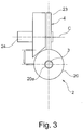
Figure 3 is a front sectional view of the welding tool offigure 2 ; -
Figure 4 is a side sectional view of a welding tool not covered by the present invention; -
Figure 5 is a side sectional view of a component of the kit offigure 1 ; -
Figure 6 is a top sectional view of the component offigure 5 ; -
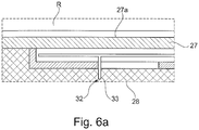
Figure 6a is an enlarged view of a detail offigure 6 ; -
Figure 7 is a front sectional view of the component offigures 5 and6 ; -
Figure 8 is a front view of a further component of the kit offigure 1 ; and -
Figure 9 is a schematic representation of the functioning of the kit offigure 1 . - The following description of exemplary embodiments refer to the accompanying drawings. The same reference numbers in different drawings identify the same or similar elements. The following detailed description does not limit the invention. Instead, the scope of the invention is defined by the appended claims.
- With reference to the attached drawings, with the number 1 is indicated an arc welding kit according to an embodiment of the present invention. The welding kit 1 comprises a
welding tool 2, which is configured to be held by a welder. - The
welding tool 2 comprises anelectrode 3, which is used, according to the present invention, to perform a SMAW (shielded metal arc weld) or a MIG (Metal Inert Gas), shown infigures 2 and3 , theelectrode 3 is consumable. In other words, according to the present invention, theelectrode 3 becomes the filler material of the weld. In an example not covered by the present invention, as shown infigure 4 , theelectrode 3 is non-consumable, thus it is used to perform a TIG (Tungsten Inert Gas) weld. - With additional details, the
welding tool 2 comprises amain body 20, configured to support theelectrode 3. Themain body 20 is preferably axial-symmetric, and develops mainly along a longitudinal axis "A". Ahandle 21 for the welder supports themain body 20. - The
main body 20 has aseat 20a in which theelectrode 3 is installed. As shown infigures 2 and4 , thewelding tool 2 is provided withbearings 22, which are attached to the main body and located in proximity of theseat 20, so that they can support theelectrode 3 and allow it to move forward and backward. In other words, theelectrode 3 can move forward and backward inside theseat 20a by sliding on thebearings 22. - Also, the
welding tool 2 comprises an adjustingdevice 4 associated with theelectrode 3, in order to move the electrode forward/backward with respect to themain body 20. The adjustingdevice 4 comprises awheel 23 having a central axis "C" disposed transversally and preferably perpendicularly, to the longitudinal axis "A" of theelectrode 3, that is parallel to the axis of themain body 20. Indeed, themain body 20 is provided with aport 25 in which thewheel 24 is inserted. - In operation, the rim of the
wheel 23 is in contact with theelectrode 3 so that theelectrode 3 can be moved along the longitudinal axis "A" by a rotation of thewheel 23 along the central axis "C". The adjustingdevice 4 also comprises amotor 24.Such motor 24 is preferably electric, more preferably an electromagnetic motor, and is installed on thewheel 23 in order to actuate thewheel 23 and through it, theelectrode 3. - When the
electrode 3 is consumable, the adjustingdevice 4 is configured for compensating the variation of distance between theelectrode 3 and the weld area due to both the consumption of the electrode and the physiologic tremor of welder hand. - This double constant adjustment allows for maintaining a substantially constant distance between the
electrode 3 and the weld area, allowing favorable arcing conditions and consequently an improved weld quality. With particular reference to the SMAW orMIG welding tool 2 offigure 2 please note that, in use, thewheel 23 advances overtime since theelectrode 3 is consumed during welding. Therefore, the rotation speed of themotor 24 provides an overall forward movement to the electrode, and varies the rotation speed in order to adjust the distance of the tip of theelectrode 3 as will be explained in a following part of the disclosure. - In the
TIG welding tool 2 offigure 4 theelectrode 3 is not consumed during welding. Therefore, thewheel 23 is moved only to adjust the distance of theelectrode 3. - Also, in
figure 4 a source of inert gas is present (not shown in the drawings) in order to shield the tip of theelectrode 3 and the weld area from atmospheric oxygen. This source of inert gas is by itself known to the person skilled in the art, thus will not be described in detail. - The kit 1 comprises a
voltage sensor 5 which is configured to detect a welding voltage "Vw" between theelectrode 3 and the weld area, that is function of the distance between the end of the electrode facing the work piece and the weld area of the work piece. Thevoltage sensor 5 is also configured to emit a voltage signal "Vs", which is representative of a value of the welding voltage "Vw".Such voltage sensor 5 can be of any type known to the person skilled in the art, and therefore will not be described in detail. - The kit 1 also comprises a
control unit 6. In the following part of the disclosure, thecontrol unit 6 will be described by subdividing it into a plurality of modules. Such subdivision is done for ease of description only, and in no way should be considered as reflecting the physical structure of thecontrol unit 6 itself. Rather, each module can be implemented as an electronic circuit on a suitable hardware support, as a software routine, subroutine or library or as both. Each module may reside on a local unit or may be distributed over a network. Also, the modules can communicate with each other either via a suitable wired or wireless protocol. - The
control unit 6 comprises adata acquisition module 7, which is configured to acquire the above mentioned voltage signal "Vw". - The
control unit 6 also comprises amemory module 16, which is configured to store a target voltage value "Vt". - The
control unit 6 also comprises aninput module 17 configured to set said target voltage value "Vt" in saidmemory module 16. In a particular embodiment of the invention theinput module 17 can be a QR code reader. In this way the voltage "Vt", as well as any other parameter related to the welding process, can be read by theinput module 17 on a suitably encoded QR code. - The
control unit 6 also comprises aprocessing module 8, which is configured to output an actuation signal "Sa" function of at least the voltage signal "Vs". Also, theprocessing module 8 is configured to retrieve the target voltage value "Vt" and to compare it with the welding voltage value "Vw". The actuation signal "Sa" is therefore at least in part directly proportional to the result of such comparison. With additional detail, theprocessing module 8 may be programmed with a PID (Proportional, Integral and Derivative) logic. Therefore, the actuation signal "Sa" may be the sum of a part directly proportional to the difference between "Vw" and Vt", of a part proportional to the derivative of such difference and of a part proportional to the integral of such difference. Any possible combination can be used, depending on the chosen control strategy. Theprocessing module 8 can also be configured to supply a voltage difference signal "Dv" representing the result of the difference between "Vw" and "Vt". - The
control unit 6 also comprises anactuation module 14 connected to theadjusting device 4. Theactuation module 14 is configured to operate theadjusting device 4 as directed by the actuation signal "Sa". In particular, theactuation module 14 operates themotor 24 which rotates thewheel 23. Optionally, the welding kit also comprises awelding mask 9.Such welding mask 9 is configured to be worn by a welder during a welding process as a standard safety mask. In particular, thewelding mask 9 comprises adarkened window 10 from which the welder may observe the welding process without being blinded by the intense light. - Additionally, the
welding mask 9 is provided with awelding velocity sensor 11. Thewelding velocity sensor 11 is configured to detect a welding velocity "Wa", and to emit a welding velocity signal "Ws" representing a value of the welding velocity "Wa". - According to a preferred embodiment of the invention, the
welding velocity sensor 11 comprises a firstoptical sensor 12a. The firstoptical sensor 12a is in particular arranged so that, during welding operation it faces the weld area. As shown infigure 8 , the first optical sensor is preferably placed on the external surface of thewelding mask 9, preferably over thedarkened window 10. Thewelding velocity sensor 11 preferably also comprises areference frame sensor 12b. Thisreference frame sensor 12b can be any kind of sensor which is able to detect a motion within a fixed frame of reference. For example, thereference frame sensor 12b can be an inertial sensor located on any point of thewelding mask 9. - With more detail, in the embodiment shown in
figure 8 thereference frame sensor 12b is a second optical sensor. Thereference frame sensor 12b is therefore preferably arranged to face a fixed reference scene in the environment, as for example the work piece part from the weld area, and placed preferably beside the firstoptical sensor 12a. In the preferred embodiment of the invention, thesensors - With additional detail, the first
optical sensor 12a is configured to detect the velocity of the welding pool relative to itself. Also, thereference frame sensor 12b is configured to detect the velocity of the above mentioned fixed reference scene. According to a first embodiment, thewelding velocity sensor 11 also comprises avelocity computing module 13 which is configured to compute the welding velocity "Wa" as a difference between the velocities detected by the second 12b and the firstoptical sensor 12a. Alternatively, the firstoptical sensor 12a andreference frame sensor 12b both transmit the respective velocities to thecontrol unit 6, in particular to thedata acquisition module 14. - The
processing module 8 is also configured to compute a velocity difference between the welding velocity "Wa" and a target velocity "Wt" value, said processing unit being configured to emit a velocity difference signal "Dw" representing the result of said velocity difference. - Optionally, the
welding mask 9 comprises avisualization device 15.Such visualization device 15 is arranged to be easily visible by the welder during the welding process. As shown infigures 1 and8 , thevisualization device 15 is preferably placed inside thewelding mask 9, preferably on one side of thedarkened window 10. - With more detail, the
visualization device 15 is configured to acquire the above mentioned velocity difference signal "Dw", thus showing a representation of the velocity difference to the welder. Similarly, thevisualization device 15 can be configured to acquire the voltage difference signal "Dv" mentioned above and to show a representation of the voltage difference to the welder. - Preferably, the
visualization device 15 can be configured to show an operating parameter of the welding process, such as the voltage (V), the current (A), the welding speed (W), respectively between the electrode and the weld area, or their combinations. As shown schematically infigure 8 , the visualization device comprises a plurality ofLEDs 26. These LEDs are preferably arranged in a cross, and are configured to lighten in such a way as to indicate whether the welder should go faster or slower, or if he should get nearer or farther from the weld area. - Referring specifically to
figures 5 and6 , the kit 1 can also comprises ahandling apparatus 18 for a filler rod "R". Thehandling apparatus 18 comprises afeeding device 19 configured to advance the filler rod "R" during welding. - With additional details, the
handling apparatus 18 comprises amain body 27, configured to support the filler rod "R". Themain body 27 is preferably axial-symmetric, and develops mainly along a longitudinal axis "B". Ahandle 28 for the welder is attached to themain body 27. Preferably, thehandle 28 surrounds themain body 27 of thehandling apparatus 18. - The
main body 27 has acentral seat 27a in which the filler rod "R" is placed. As shown infigure 5 , thehandling apparatus 18 is provided withbearings 29, which are attached to themain body 27 and located in proximity of thecentral seat 27a, to support the filler rod "R" and allow it to move forward/backward. In other words, the filler rod "R" can move forward/backward inside theseat 27a by sliding on thebearings 29. - The
feeding device 19 comprises awheel 30 having a central axis "D" disposed transversally, and preferably perpendicularly to the longitudinal axis "B" of themain body 27. - In operation, the rim of the
wheel 30 is in contact with the filler rod "R" so that it can be moved along the longitudinal axis "B" by a rotation of thewheel 30 along the central axis "D". Thefeeding device 19 also comprises amotor 31.Such motor 31 is preferably electric, more preferably linear electromagnetic, and is installed on thewheel 30 in order to actuate the filler rod "R". - In an alternative embodiment, not shown in the drawings, the
feeding device 19 comprises an electromagnetic actuation device for the filler rod "R" instead of thewheel 30 and themotor 31. - If the
handling apparatus 18 is used, theprocessing module 8 may be configured to emit a feeding velocity signal "Sv" to theactuation module 14. The feeding velocity signal "Sv" is preferably proportional to a feeding velocity value "Fv". Theactuation module 14 is therefore also configured to operate thefeeding device 19 of thehandling apparatus 18 as directed by the feeding velocity signal "Sv". - Also, as shown in
figure 6a , thehandling apparatus 18 comprises acontrol interface 32 associated with theprocessing module 8. Thecontrol interface 32 is configured to emit a command signal "Cv" to theprocessing module 8, so that the welder can increase or decrease the feeding velocity signal "Sa". - With additional detail, the
control interface 32 comprises abutton 33 placed on thehandle 28. Specifically, thebutton 33 allows the welder to adjust the feeding velocity continuously; however thebutton 33 is designed as to give a tactile feedback in the form of "clicks" at predetermined intervals so that the welder can be made aware with a certain precision of the amount that the feeding velocity is being manually increased or decreased.
Claims (10)
- A welding tool (2) comprising a main body (20); a handle (21) attached to said main body (20) and configured to be held by a welder; and an electrode (3); characterized by an adjusting device (4) attached to said main body (20) and associated with said electrode (3) for moving said electrode (3) forward/backward with respect to said main body (20); and a control unit (6) connected to said adjusting device (4) and configured to act on said adjusting device (4) for maintaining a substantially constant distance between said electrode (3) and a weld area; wherein said electrode (3) is consumable for performing a SMAW or a MIG weld, the welding tool (2) also comprising a voltage sensor (5) configured to detect a welding voltage (Vw) between said electrode (3) and said weld area and to emit a voltage signal (Vs) representing a value of said welding voltage (Vw), said voltage sensor (5) being connected to said control unit (6), wherein said control unit (6) comprises a data acquisition module (7) configured to acquire said voltage signal (Vw), a processing module (8) configured to output an actuation signal (Sa) function of at least said voltage signal (Vs), an actuation module (14) connected to said adjusting device (4) and configured to operate said adjusting device (4) as directed by said actuation signal (Sa).
- A welding tool (2) according to the preceding claim, wherein the control unit (6) also comprises a memory module (16) configured to hold a target voltage value (Vt), said processing module (8) being configured to retrieve said target voltage value (Vt) and to compare it with said welding voltage value (Vw), said actuation signal (Sa) being at least in part directly proportional to the result of said comparison.
- A welding tool (2) according to any preceding claim, wherein the control unit (6) also comprises an input module (17) configured to set said target voltage value (Vt) in said memory module (16).
- A welding tool (2) according to claim 3, wherein the input module (17) is a QR code reader for reading said target voltage value (Vt) from a QR code.
- A welding tool (2) according to any one of the previous claims, wherein said adjusting device (4) comprises a wheel (23) having a central axis (C) disposed transversally, and preferably perpendicularly, to a longitudinal axis (A) of the electrode (3), the rim of said wheel (23) being in contact with said electrode (3) for moving said electrode (3) forward/backward with respect to said main body (20).
- A welding tool (2) according to the previous claim, wherein said adjusting device (4) comprises a motor (24), preferably electric, said motor (24) being connected to said wheel (23) for actuating said wheel (23).
- A welding tool (2) according to the previous claim, wherein the motor (24) is a linear electromagnetic motor.
- An arc welding kit (1) comprising a welding tool (2) according to any one of the previous claims; a welding mask (9); a visualization device (15) attached to said welding mask and arranged to show a representation of at least a performance of a welding operation selected from: welding speed (W), voltage (V), current (A), respectively between the electrode and the weld area.
- An arc welding kit (1) according to the previous claim, wherein the welding mask (9) further comprises a welding velocity sensor (11) attached on the welding mask (9), said welding velocity sensor (11) being configured to detect a welding velocity (Wa) and to emit a welding velocity signal (Ws) representing a value of said welding velocity (Wa), said processing module (8) being configured to compute a velocity difference between said welding velocity (Wa) and a target velocity (Wt) value for said welding velocity, said processing module (8) being configured to emit a velocity difference signal (Dw) representing the result of said velocity difference; visualization device (15) being configured to acquire said velocity difference signal (Dw) and to show a representation of said velocity difference and of consequent heat input difference to a welder.
- An arc welding kit (1) according to claim 8 or claim 9, wherein said processing module (8) is configured to compute a voltage difference between said welding voltage (Vw) and said target voltage (Vt), said processing module (8) being configured to emit a voltage difference signal (Dv) representing the result of said voltage difference; said visualization device (15) being configured to acquire said voltage difference signal (Dv) and to show a representation of said voltage difference to a welder.
Applications Claiming Priority (2)
| Application Number | Priority Date | Filing Date | Title |
|---|---|---|---|
| ITMI20142040 | 2014-11-27 | ||
| PCT/EP2015/077591 WO2016083429A1 (en) | 2014-11-27 | 2015-11-25 | Welding tool for performing smaw or mig weld with maintenance of a constatn distance between the electrode and the weld area |
Publications (2)
| Publication Number | Publication Date |
|---|---|
| EP3223988A1 EP3223988A1 (en) | 2017-10-04 |
| EP3223988B1 true EP3223988B1 (en) | 2020-12-30 |
Family
ID=52444438
Family Applications (1)
| Application Number | Title | Priority Date | Filing Date |
|---|---|---|---|
| EP15798473.3A Active EP3223988B1 (en) | 2014-11-27 | 2015-11-25 | Welding tool for performing smaw or mig weld with maintenance of a constant distance between the electrode and the weld area |
Country Status (8)
| Country | Link |
|---|---|
| US (1) | US10906118B2 (en) |
| EP (1) | EP3223988B1 (en) |
| JP (1) | JP2017535434A (en) |
| KR (1) | KR102429735B1 (en) |
| CN (1) | CN107206521A (en) |
| ES (1) | ES2855113T3 (en) |
| RU (1) | RU2699884C2 (en) |
| WO (1) | WO2016083429A1 (en) |
Families Citing this family (3)
| Publication number | Priority date | Publication date | Assignee | Title |
|---|---|---|---|---|
| CN106923964B (en) * | 2017-04-18 | 2023-03-10 | 贵州建工集团第二建筑工程有限责任公司 | Simple device for preventing arc light pollution of electric welding |
| US11311958B1 (en) * | 2019-05-13 | 2022-04-26 | Airgas, Inc. | Digital welding and cutting efficiency analysis, process evaluation and response feedback system for process optimization |
| FR3127424A1 (en) * | 2021-09-24 | 2023-03-31 | Gys | Adapter for mounting a ceramic nozzle on a welding torch in gasless operation |
Family Cites Families (23)
| Publication number | Priority date | Publication date | Assignee | Title |
|---|---|---|---|---|
| SU118924A1 (en) * | 1958-06-09 | 1958-11-30 | Г.П. Клековкин | Welding gun for pulsed arc welding and welding |
| US3030489A (en) * | 1959-12-07 | 1962-04-17 | Union Carbide Corp | Gas shielded arc torch |
| US3261961A (en) * | 1964-12-07 | 1966-07-19 | British Oxygen Co Ltd | Apparatus for arc welding and similar processes |
| JPS5788978A (en) * | 1980-11-21 | 1982-06-03 | Matsushita Electric Ind Co Ltd | Method for controlling feeding of filler wire |
| SU1636154A1 (en) * | 1988-12-26 | 1991-03-23 | Львовский политехнический институт им.Ленинского комсомола | Device for control of semi-automatic welding machine |
| JPH1152755A (en) | 1997-08-08 | 1999-02-26 | Fuji Xerox Co Ltd | Image forming device |
| JP3654617B2 (en) * | 1997-12-24 | 2005-06-02 | 東京瓦斯株式会社 | Welding machine control method |
| JPH11267922A (en) * | 1998-03-23 | 1999-10-05 | Honda Motor Co Ltd | Applicable ball screw manufacturing method |
| JP2001071135A (en) * | 1999-09-03 | 2001-03-21 | Somakkusu Kk | Welding equipment for repair |
| JP2001129666A (en) * | 1999-11-04 | 2001-05-15 | Somakkusu Kk | Welding system for repair |
| US6242711B1 (en) * | 1999-12-27 | 2001-06-05 | Accudata, Inc. | Arc welding monitoring system |
| CA2485302A1 (en) * | 2003-12-31 | 2005-06-30 | Illinois Tool Works Inc. | Dual-process power cable with interchangeable tig welding torch and smaw electrode holder |
| DE102004049375A1 (en) * | 2004-10-09 | 2006-04-13 | Rovema Verpackungsmaschinen Gmbh | Method and device for positioning a welding jaw |
| CN200957488Y (en) * | 2006-09-05 | 2007-10-10 | 中国石油天然气集团公司 | Automatic of magnetic-adsorbing oil tank |
| US7962967B2 (en) * | 2008-05-09 | 2011-06-21 | Illinois Tool Works Inc. | Weld characteristic communication system for a welding mask |
| US8569654B2 (en) | 2009-06-11 | 2013-10-29 | Illinois Tool Works Inc. | Systems and methods for wire feed speed control |
| DE202010012928U1 (en) * | 2010-11-18 | 2011-01-20 | ALGÜN, Osman | Welding wire transmitter |
| US20120180180A1 (en) * | 2010-12-16 | 2012-07-19 | Mann Steve | Seeing aid or other sensory aid or interface for activities such as electric arc welding |
| CN201913352U (en) * | 2010-12-20 | 2011-08-03 | 北京时代科技股份有限公司 | Strip surfacing machine head capable of adjusting strip width |
| US8998035B2 (en) * | 2012-02-24 | 2015-04-07 | Bunn-O-Matic Corporation | Liquid beverage concentrate dispensing system |
| KR101855686B1 (en) * | 2012-03-29 | 2018-05-08 | 다이요 닛산 가부시키가이샤 | Semiautomatic welding system, conversion adapter kit, and welding torch |
| DE102013207193A1 (en) * | 2013-04-22 | 2014-10-23 | Robert Bosch Gmbh | Microhydraulic system, especially for use in planar microfluidic laboratories |
| US20140367366A1 (en) * | 2013-06-14 | 2014-12-18 | Hobart Brothers Company | Systems and methods of conditioning an air flow for a welding environment |
-
2015
- 2015-11-25 ES ES15798473T patent/ES2855113T3/en active Active
- 2015-11-25 RU RU2017116426A patent/RU2699884C2/en active
- 2015-11-25 KR KR1020177017133A patent/KR102429735B1/en active Active
- 2015-11-25 JP JP2017528106A patent/JP2017535434A/en active Pending
- 2015-11-25 EP EP15798473.3A patent/EP3223988B1/en active Active
- 2015-11-25 US US15/529,770 patent/US10906118B2/en active Active
- 2015-11-25 WO PCT/EP2015/077591 patent/WO2016083429A1/en not_active Ceased
- 2015-11-25 CN CN201580064731.5A patent/CN107206521A/en active Pending
Non-Patent Citations (1)
| Title |
|---|
| None * |
Also Published As
| Publication number | Publication date |
|---|---|
| US10906118B2 (en) | 2021-02-02 |
| WO2016083429A8 (en) | 2017-06-01 |
| KR20170086624A (en) | 2017-07-26 |
| RU2699884C2 (en) | 2019-09-11 |
| CN107206521A (en) | 2017-09-26 |
| WO2016083429A1 (en) | 2016-06-02 |
| KR102429735B1 (en) | 2022-08-05 |
| ES2855113T3 (en) | 2021-09-23 |
| US20170326671A1 (en) | 2017-11-16 |
| EP3223988A1 (en) | 2017-10-04 |
| RU2017116426A3 (en) | 2019-04-29 |
| RU2017116426A (en) | 2018-12-27 |
| JP2017535434A (en) | 2017-11-30 |
Similar Documents
| Publication | Publication Date | Title |
|---|---|---|
| US11524368B2 (en) | Augmented vision system with active welder guidance | |
| US5302799A (en) | Weld analysis and control system | |
| EP3676041B1 (en) | Method and system using a smart torch with positional tracking in robotic welding | |
| US9922460B2 (en) | Stereoscopic helmet display | |
| EP3247523B1 (en) | Weld output control by a welding vision system | |
| US12465995B2 (en) | Remote power supply parameter adjustment | |
| EP3223989B1 (en) | Handling apparatus for performing a tig weld with regulation of speed of the fed wire, and arc welding kit with such apparatus | |
| US10906118B2 (en) | Welding tool for performing SMAW or MIG weld with mantenance of a constant distance between the electrode and the weld area | |
| CN110662620A (en) | Method and device for marking the surface of a metal workpiece using a welding wire electrode | |
| US20170326673A1 (en) | Welding assistance device with a welding mask having a velocity sensor | |
| US20250083317A1 (en) | Welding robot workpiece sensing | |
| Kennedy et al. | Weld analysis and control system |
Legal Events
| Date | Code | Title | Description |
|---|---|---|---|
| STAA | Information on the status of an ep patent application or granted ep patent |
Free format text: STATUS: THE INTERNATIONAL PUBLICATION HAS BEEN MADE |
|
| PUAI | Public reference made under article 153(3) epc to a published international application that has entered the european phase |
Free format text: ORIGINAL CODE: 0009012 |
|
| STAA | Information on the status of an ep patent application or granted ep patent |
Free format text: STATUS: REQUEST FOR EXAMINATION WAS MADE |
|
| 17P | Request for examination filed |
Effective date: 20170627 |
|
| AK | Designated contracting states |
Kind code of ref document: A1 Designated state(s): AL AT BE BG CH CY CZ DE DK EE ES FI FR GB GR HR HU IE IS IT LI LT LU LV MC MK MT NL NO PL PT RO RS SE SI SK SM TR |
|
| AX | Request for extension of the european patent |
Extension state: BA ME |
|
| DAV | Request for validation of the european patent (deleted) | ||
| DAX | Request for extension of the european patent (deleted) | ||
| STAA | Information on the status of an ep patent application or granted ep patent |
Free format text: STATUS: EXAMINATION IS IN PROGRESS |
|
| 17Q | First examination report despatched |
Effective date: 20180713 |
|
| GRAP | Despatch of communication of intention to grant a patent |
Free format text: ORIGINAL CODE: EPIDOSNIGR1 |
|
| STAA | Information on the status of an ep patent application or granted ep patent |
Free format text: STATUS: GRANT OF PATENT IS INTENDED |
|
| INTG | Intention to grant announced |
Effective date: 20200629 |
|
| GRAS | Grant fee paid |
Free format text: ORIGINAL CODE: EPIDOSNIGR3 |
|
| GRAA | (expected) grant |
Free format text: ORIGINAL CODE: 0009210 |
|
| STAA | Information on the status of an ep patent application or granted ep patent |
Free format text: STATUS: THE PATENT HAS BEEN GRANTED |
|
| AK | Designated contracting states |
Kind code of ref document: B1 Designated state(s): AL AT BE BG CH CY CZ DE DK EE ES FI FR GB GR HR HU IE IS IT LI LT LU LV MC MK MT NL NO PL PT RO RS SE SI SK SM TR |
|
| REG | Reference to a national code |
Ref country code: GB Ref legal event code: FG4D |
|
| REG | Reference to a national code |
Ref country code: DE Ref legal event code: R096 Ref document number: 602015064197 Country of ref document: DE |
|
| REG | Reference to a national code |
Ref country code: AT Ref legal event code: REF Ref document number: 1349436 Country of ref document: AT Kind code of ref document: T Effective date: 20210115 |
|
| REG | Reference to a national code |
Ref country code: IE Ref legal event code: FG4D |
|
| PG25 | Lapsed in a contracting state [announced via postgrant information from national office to epo] |
Ref country code: GR Free format text: LAPSE BECAUSE OF FAILURE TO SUBMIT A TRANSLATION OF THE DESCRIPTION OR TO PAY THE FEE WITHIN THE PRESCRIBED TIME-LIMIT Effective date: 20210331 Ref country code: RS Free format text: LAPSE BECAUSE OF FAILURE TO SUBMIT A TRANSLATION OF THE DESCRIPTION OR TO PAY THE FEE WITHIN THE PRESCRIBED TIME-LIMIT Effective date: 20201230 Ref country code: FI Free format text: LAPSE BECAUSE OF FAILURE TO SUBMIT A TRANSLATION OF THE DESCRIPTION OR TO PAY THE FEE WITHIN THE PRESCRIBED TIME-LIMIT Effective date: 20201230 Ref country code: NO Free format text: LAPSE BECAUSE OF FAILURE TO SUBMIT A TRANSLATION OF THE DESCRIPTION OR TO PAY THE FEE WITHIN THE PRESCRIBED TIME-LIMIT Effective date: 20210330 |
|
| REG | Reference to a national code |
Ref country code: AT Ref legal event code: MK05 Ref document number: 1349436 Country of ref document: AT Kind code of ref document: T Effective date: 20201230 |
|
| PG25 | Lapsed in a contracting state [announced via postgrant information from national office to epo] |
Ref country code: BG Free format text: LAPSE BECAUSE OF FAILURE TO SUBMIT A TRANSLATION OF THE DESCRIPTION OR TO PAY THE FEE WITHIN THE PRESCRIBED TIME-LIMIT Effective date: 20210330 Ref country code: LV Free format text: LAPSE BECAUSE OF FAILURE TO SUBMIT A TRANSLATION OF THE DESCRIPTION OR TO PAY THE FEE WITHIN THE PRESCRIBED TIME-LIMIT Effective date: 20201230 Ref country code: SE Free format text: LAPSE BECAUSE OF FAILURE TO SUBMIT A TRANSLATION OF THE DESCRIPTION OR TO PAY THE FEE WITHIN THE PRESCRIBED TIME-LIMIT Effective date: 20201230 |
|
| REG | Reference to a national code |
Ref country code: NL Ref legal event code: MP Effective date: 20201230 |
|
| PG25 | Lapsed in a contracting state [announced via postgrant information from national office to epo] |
Ref country code: HR Free format text: LAPSE BECAUSE OF FAILURE TO SUBMIT A TRANSLATION OF THE DESCRIPTION OR TO PAY THE FEE WITHIN THE PRESCRIBED TIME-LIMIT Effective date: 20201230 |
|
| REG | Reference to a national code |
Ref country code: LT Ref legal event code: MG9D |
|
| PG25 | Lapsed in a contracting state [announced via postgrant information from national office to epo] |
Ref country code: CZ Free format text: LAPSE BECAUSE OF FAILURE TO SUBMIT A TRANSLATION OF THE DESCRIPTION OR TO PAY THE FEE WITHIN THE PRESCRIBED TIME-LIMIT Effective date: 20201230 Ref country code: EE Free format text: LAPSE BECAUSE OF FAILURE TO SUBMIT A TRANSLATION OF THE DESCRIPTION OR TO PAY THE FEE WITHIN THE PRESCRIBED TIME-LIMIT Effective date: 20201230 Ref country code: LT Free format text: LAPSE BECAUSE OF FAILURE TO SUBMIT A TRANSLATION OF THE DESCRIPTION OR TO PAY THE FEE WITHIN THE PRESCRIBED TIME-LIMIT Effective date: 20201230 Ref country code: PT Free format text: LAPSE BECAUSE OF FAILURE TO SUBMIT A TRANSLATION OF THE DESCRIPTION OR TO PAY THE FEE WITHIN THE PRESCRIBED TIME-LIMIT Effective date: 20210430 Ref country code: SK Free format text: LAPSE BECAUSE OF FAILURE TO SUBMIT A TRANSLATION OF THE DESCRIPTION OR TO PAY THE FEE WITHIN THE PRESCRIBED TIME-LIMIT Effective date: 20201230 Ref country code: RO Free format text: LAPSE BECAUSE OF FAILURE TO SUBMIT A TRANSLATION OF THE DESCRIPTION OR TO PAY THE FEE WITHIN THE PRESCRIBED TIME-LIMIT Effective date: 20201230 |
|
| PG25 | Lapsed in a contracting state [announced via postgrant information from national office to epo] |
Ref country code: PL Free format text: LAPSE BECAUSE OF FAILURE TO SUBMIT A TRANSLATION OF THE DESCRIPTION OR TO PAY THE FEE WITHIN THE PRESCRIBED TIME-LIMIT Effective date: 20201230 Ref country code: AT Free format text: LAPSE BECAUSE OF FAILURE TO SUBMIT A TRANSLATION OF THE DESCRIPTION OR TO PAY THE FEE WITHIN THE PRESCRIBED TIME-LIMIT Effective date: 20201230 |
|
| REG | Reference to a national code |
Ref country code: ES Ref legal event code: FG2A Ref document number: 2855113 Country of ref document: ES Kind code of ref document: T3 Effective date: 20210923 |
|
| PG25 | Lapsed in a contracting state [announced via postgrant information from national office to epo] |
Ref country code: IS Free format text: LAPSE BECAUSE OF FAILURE TO SUBMIT A TRANSLATION OF THE DESCRIPTION OR TO PAY THE FEE WITHIN THE PRESCRIBED TIME-LIMIT Effective date: 20210430 |
|
| REG | Reference to a national code |
Ref country code: DE Ref legal event code: R097 Ref document number: 602015064197 Country of ref document: DE |
|
| PG25 | Lapsed in a contracting state [announced via postgrant information from national office to epo] |
Ref country code: IT Free format text: LAPSE BECAUSE OF FAILURE TO SUBMIT A TRANSLATION OF THE DESCRIPTION OR TO PAY THE FEE WITHIN THE PRESCRIBED TIME-LIMIT Effective date: 20201230 Ref country code: AL Free format text: LAPSE BECAUSE OF FAILURE TO SUBMIT A TRANSLATION OF THE DESCRIPTION OR TO PAY THE FEE WITHIN THE PRESCRIBED TIME-LIMIT Effective date: 20201230 |
|
| PLBE | No opposition filed within time limit |
Free format text: ORIGINAL CODE: 0009261 |
|
| STAA | Information on the status of an ep patent application or granted ep patent |
Free format text: STATUS: NO OPPOSITION FILED WITHIN TIME LIMIT |
|
| PG25 | Lapsed in a contracting state [announced via postgrant information from national office to epo] |
Ref country code: DK Free format text: LAPSE BECAUSE OF FAILURE TO SUBMIT A TRANSLATION OF THE DESCRIPTION OR TO PAY THE FEE WITHIN THE PRESCRIBED TIME-LIMIT Effective date: 20201230 |
|
| 26N | No opposition filed |
Effective date: 20211001 |
|
| PG25 | Lapsed in a contracting state [announced via postgrant information from national office to epo] |
Ref country code: SI Free format text: LAPSE BECAUSE OF FAILURE TO SUBMIT A TRANSLATION OF THE DESCRIPTION OR TO PAY THE FEE WITHIN THE PRESCRIBED TIME-LIMIT Effective date: 20201230 |
|
| REG | Reference to a national code |
Ref country code: CH Ref legal event code: PK Free format text: BERICHTIGUNGEN |
|
| PG25 | Lapsed in a contracting state [announced via postgrant information from national office to epo] |
Ref country code: IS Free format text: LAPSE BECAUSE OF FAILURE TO SUBMIT A TRANSLATION OF THE DESCRIPTION OR TO PAY THE FEE WITHIN THE PRESCRIBED TIME-LIMIT Effective date: 20210430 |
|
| PG25 | Lapsed in a contracting state [announced via postgrant information from national office to epo] |
Ref country code: MC Free format text: LAPSE BECAUSE OF FAILURE TO SUBMIT A TRANSLATION OF THE DESCRIPTION OR TO PAY THE FEE WITHIN THE PRESCRIBED TIME-LIMIT Effective date: 20201230 |
|
| REG | Reference to a national code |
Ref country code: ES Ref legal event code: PC2A Owner name: NUOVO PIGNONE TECNOLOGIE - S.R.L. Effective date: 20220628 |
|
| PG25 | Lapsed in a contracting state [announced via postgrant information from national office to epo] |
Ref country code: LU Free format text: LAPSE BECAUSE OF NON-PAYMENT OF DUE FEES Effective date: 20211125 Ref country code: BE Free format text: LAPSE BECAUSE OF NON-PAYMENT OF DUE FEES Effective date: 20211130 |
|
| REG | Reference to a national code |
Ref country code: BE Ref legal event code: MM Effective date: 20211130 |
|
| REG | Reference to a national code |
Ref country code: GB Ref legal event code: 732E Free format text: REGISTERED BETWEEN 20220728 AND 20220803 |
|
| PG25 | Lapsed in a contracting state [announced via postgrant information from national office to epo] |
Ref country code: IE Free format text: LAPSE BECAUSE OF NON-PAYMENT OF DUE FEES Effective date: 20211125 |
|
| PG25 | Lapsed in a contracting state [announced via postgrant information from national office to epo] |
Ref country code: FR Free format text: LAPSE BECAUSE OF NON-PAYMENT OF DUE FEES Effective date: 20211130 |
|
| PG25 | Lapsed in a contracting state [announced via postgrant information from national office to epo] |
Ref country code: HU Free format text: LAPSE BECAUSE OF FAILURE TO SUBMIT A TRANSLATION OF THE DESCRIPTION OR TO PAY THE FEE WITHIN THE PRESCRIBED TIME-LIMIT; INVALID AB INITIO Effective date: 20151125 |
|
| PG25 | Lapsed in a contracting state [announced via postgrant information from national office to epo] |
Ref country code: NL Free format text: LAPSE BECAUSE OF NON-PAYMENT OF DUE FEES Effective date: 20201230 Ref country code: CY Free format text: LAPSE BECAUSE OF FAILURE TO SUBMIT A TRANSLATION OF THE DESCRIPTION OR TO PAY THE FEE WITHIN THE PRESCRIBED TIME-LIMIT Effective date: 20201230 |
|
| P01 | Opt-out of the competence of the unified patent court (upc) registered |
Effective date: 20230526 |
|
| PG25 | Lapsed in a contracting state [announced via postgrant information from national office to epo] |
Ref country code: SM Free format text: LAPSE BECAUSE OF FAILURE TO SUBMIT A TRANSLATION OF THE DESCRIPTION OR TO PAY THE FEE WITHIN THE PRESCRIBED TIME-LIMIT Effective date: 20201230 |
|
| PG25 | Lapsed in a contracting state [announced via postgrant information from national office to epo] |
Ref country code: MK Free format text: LAPSE BECAUSE OF FAILURE TO SUBMIT A TRANSLATION OF THE DESCRIPTION OR TO PAY THE FEE WITHIN THE PRESCRIBED TIME-LIMIT Effective date: 20201230 |
|
| REG | Reference to a national code |
Ref country code: DE Ref legal event code: R081 Ref document number: 602015064197 Country of ref document: DE Owner name: NUOVO PIGNONE TECNOLOGIE - S.R.L., IT Free format text: FORMER OWNER: NUOVO PIGNONE S.R.L., 50127 FLORENCE, IT |
|
| PG25 | Lapsed in a contracting state [announced via postgrant information from national office to epo] |
Ref country code: MT Free format text: LAPSE BECAUSE OF FAILURE TO SUBMIT A TRANSLATION OF THE DESCRIPTION OR TO PAY THE FEE WITHIN THE PRESCRIBED TIME-LIMIT Effective date: 20201230 |
|
| REG | Reference to a national code |
Ref country code: CH Ref legal event code: U11 Free format text: ST27 STATUS EVENT CODE: U-0-0-U10-U11 (AS PROVIDED BY THE NATIONAL OFFICE) Effective date: 20251201 |
|
| PG25 | Lapsed in a contracting state [announced via postgrant information from national office to epo] |
Ref country code: TR Free format text: LAPSE BECAUSE OF FAILURE TO SUBMIT A TRANSLATION OF THE DESCRIPTION OR TO PAY THE FEE WITHIN THE PRESCRIBED TIME-LIMIT Effective date: 20201230 |
|
| PGFP | Annual fee paid to national office [announced via postgrant information from national office to epo] |
Ref country code: DE Payment date: 20251022 Year of fee payment: 11 |
|
| PGFP | Annual fee paid to national office [announced via postgrant information from national office to epo] |
Ref country code: GB Payment date: 20251023 Year of fee payment: 11 |
|
| PGFP | Annual fee paid to national office [announced via postgrant information from national office to epo] |
Ref country code: CH Payment date: 20251201 Year of fee payment: 11 |
|
| PGFP | Annual fee paid to national office [announced via postgrant information from national office to epo] |
Ref country code: ES Payment date: 20251201 Year of fee payment: 11 |