EP3223720B1 - Tissue ligation apparatus with a rotating spool assembly and a valve assembly - Google Patents
Tissue ligation apparatus with a rotating spool assembly and a valve assembly Download PDFInfo
- Publication number
- EP3223720B1 EP3223720B1 EP15862863.6A EP15862863A EP3223720B1 EP 3223720 B1 EP3223720 B1 EP 3223720B1 EP 15862863 A EP15862863 A EP 15862863A EP 3223720 B1 EP3223720 B1 EP 3223720B1
- Authority
- EP
- European Patent Office
- Prior art keywords
- wire
- distal end
- lumen
- proximal end
- braided cord
- Prior art date
- Legal status (The legal status is an assumption and is not a legal conclusion. Google has not performed a legal analysis and makes no representation as to the accuracy of the status listed.)
- Active
Links
- 239000011324 bead Substances 0.000 claims description 29
- 230000013011 mating Effects 0.000 claims description 23
- 238000007789 sealing Methods 0.000 claims description 5
- 238000011010 flushing procedure Methods 0.000 claims description 4
- 229920000642 polymer Polymers 0.000 claims description 4
- 229910052751 metal Inorganic materials 0.000 claims description 3
- 239000002184 metal Substances 0.000 claims description 3
- 238000009954 braiding Methods 0.000 claims description 2
- 238000000034 method Methods 0.000 description 25
- 208000014617 hemorrhoid Diseases 0.000 description 7
- 206010046996 Varicose vein Diseases 0.000 description 5
- 208000027185 varicose disease Diseases 0.000 description 5
- 230000008901 benefit Effects 0.000 description 4
- 238000010168 coupling process Methods 0.000 description 4
- 230000000740 bleeding effect Effects 0.000 description 3
- 230000008878 coupling Effects 0.000 description 3
- 238000005859 coupling reaction Methods 0.000 description 3
- 210000001035 gastrointestinal tract Anatomy 0.000 description 3
- 238000003780 insertion Methods 0.000 description 3
- 230000037431 insertion Effects 0.000 description 3
- 208000000624 Esophageal and Gastric Varices Diseases 0.000 description 2
- 206010056091 Varices oesophageal Diseases 0.000 description 2
- 238000013461 design Methods 0.000 description 2
- 208000024170 esophageal varices Diseases 0.000 description 2
- 201000010120 esophageal varix Diseases 0.000 description 2
- 210000003238 esophagus Anatomy 0.000 description 2
- 239000012530 fluid Substances 0.000 description 2
- 238000004519 manufacturing process Methods 0.000 description 2
- 230000008569 process Effects 0.000 description 2
- 206010003497 Asphyxia Diseases 0.000 description 1
- 206010058314 Dysplasia Diseases 0.000 description 1
- 206010056626 Pseudopolyp Diseases 0.000 description 1
- 208000015815 Rectal disease Diseases 0.000 description 1
- RTAQQCXQSZGOHL-UHFFFAOYSA-N Titanium Chemical compound [Ti] RTAQQCXQSZGOHL-UHFFFAOYSA-N 0.000 description 1
- 210000003484 anatomy Anatomy 0.000 description 1
- 230000009286 beneficial effect Effects 0.000 description 1
- 238000002052 colonoscopy Methods 0.000 description 1
- 238000010276 construction Methods 0.000 description 1
- 238000012326 endoscopic mucosal resection Methods 0.000 description 1
- 238000012143 endoscopic resection Methods 0.000 description 1
- 230000009191 jumping Effects 0.000 description 1
- 230000003902 lesion Effects 0.000 description 1
- 230000004807 localization Effects 0.000 description 1
- 230000007774 longterm Effects 0.000 description 1
- 239000000463 material Substances 0.000 description 1
- 150000002739 metals Chemical class 0.000 description 1
- 238000012986 modification Methods 0.000 description 1
- 230000004048 modification Effects 0.000 description 1
- 230000001613 neoplastic effect Effects 0.000 description 1
- 238000002271 resection Methods 0.000 description 1
- 238000002579 sigmoidoscopy Methods 0.000 description 1
- 229910001220 stainless steel Inorganic materials 0.000 description 1
- 239000010935 stainless steel Substances 0.000 description 1
- 230000001954 sterilising effect Effects 0.000 description 1
- 238000004659 sterilization and disinfection Methods 0.000 description 1
- 238000001356 surgical procedure Methods 0.000 description 1
- 239000010936 titanium Substances 0.000 description 1
- 229910052719 titanium Inorganic materials 0.000 description 1
- 210000003462 vein Anatomy 0.000 description 1
- 230000000007 visual effect Effects 0.000 description 1
- 238000012800 visualization Methods 0.000 description 1
Images


Classifications
-
- A—HUMAN NECESSITIES
- A61—MEDICAL OR VETERINARY SCIENCE; HYGIENE
- A61B—DIAGNOSIS; SURGERY; IDENTIFICATION
- A61B17/00—Surgical instruments, devices or methods, e.g. tourniquets
- A61B17/12—Surgical instruments, devices or methods, e.g. tourniquets for ligaturing or otherwise compressing tubular parts of the body, e.g. blood vessels, umbilical cord
- A61B17/12009—Implements for ligaturing other than by clamps or clips, e.g. using a loop with a slip knot
- A61B17/12013—Implements for ligaturing other than by clamps or clips, e.g. using a loop with a slip knot for use in minimally invasive surgery, e.g. endoscopic surgery
-
- A—HUMAN NECESSITIES
- A61—MEDICAL OR VETERINARY SCIENCE; HYGIENE
- A61B—DIAGNOSIS; SURGERY; IDENTIFICATION
- A61B17/00—Surgical instruments, devices or methods, e.g. tourniquets
- A61B17/00234—Surgical instruments, devices or methods, e.g. tourniquets for minimally invasive surgery
- A61B2017/00292—Surgical instruments, devices or methods, e.g. tourniquets for minimally invasive surgery mounted on or guided by flexible, e.g. catheter-like, means
- A61B2017/00296—Surgical instruments, devices or methods, e.g. tourniquets for minimally invasive surgery mounted on or guided by flexible, e.g. catheter-like, means mounted on an endoscope
-
- A—HUMAN NECESSITIES
- A61—MEDICAL OR VETERINARY SCIENCE; HYGIENE
- A61B—DIAGNOSIS; SURGERY; IDENTIFICATION
- A61B17/00—Surgical instruments, devices or methods, e.g. tourniquets
- A61B17/12—Surgical instruments, devices or methods, e.g. tourniquets for ligaturing or otherwise compressing tubular parts of the body, e.g. blood vessels, umbilical cord
- A61B17/12009—Implements for ligaturing other than by clamps or clips, e.g. using a loop with a slip knot
- A61B2017/12018—Elastic band ligators
Definitions
- the present disclosure relates generally to tissue ligation.
- Esophageal varices Swollen and enlarged veins in the esophagus are commonly called esophageal varices.
- Esophageal varices have the potential to rupture and cause excessive bleeding in the esophagus, which can cause death in certain circumstances.
- Ligation of the varices can be performed to treat bleeding varices. Ligation can also be performed as a preventative measure to strangulate and remove the varices before they reach a stage where bleeding is a distinct risk.
- the varices For ligation to be successfully performed through common practice, the varices must be pulled into a hollow chamber through suction, whereby elastic ligation bands are released over the tissue to strangulate it. Strangulation leads to death of the tissue and the subsequent natural detachment of the varices.
- Endoscopic hemorrhoid band ligation similar in technique to the variceal banding described above is an important advancement in the treatment of symptomatic internal hemorrhoids (IH).
- IH symptomatic internal hemorrhoids
- Multiple rubber bands can be applied in one session, and further bands can be applied in subsequent sessions if a single session fails to completely eradicate the internal hemorrhoids.
- the treatment success rate is high, while the long-term recurrence rate is low.
- Symptomatic hemorrhoids in adults is considered one of the most prevalent anorectal disorders.
- Hemorrhoids of different grades can be found in more than 80%-90% of patients undergoing sigmoidoscopy or colonoscopy. Hemorrhoids are either internal or external depending on the localization above or below the dentate line.
- a new successful technique for the treatment of high grade dysplasia is endoscopic mucosal resection. This involves the piece-meal endoscopic resection of early neoplastic lesions larger than 15-20 mm. Before using band ligation, this was a laborious procedure. Multiband mucosectomy is a new safe and very effective technique using a modified variceal band ligator. Sub-mucosal lifting and pre-looping of the snare in the cap is not necessary and multiple resections can be performed with a single snare. The ligator suctions the targeted tissue into pseudo polyps and then the snare removes them in succession.
- Endoscopes generally consist of a rigid or flexible tube with a working channel of varying internal diameters to allow a variety of medical instruments to be deployed and used in the human digestive tract. Endoscopes also feature a camera on the distal tip of the flexible tube to allow direct visualization of the digestive tract as well as light, suction and fluid delivery systems.
- Multi-band ligation devices Devices that facilitate this functionality are commonly called multi-band ligation devices. These devices consist of a hollow cylindrical barrel component which fits on the distal end of the endoscope, and that is configured to apply multiple bands over tissue suctioned into the device. There are many examples of multi-band ligation devices currently in use today. As well as this, a variety of instruments for effecting the ligation of body tissue by the application of an elastic band are known in the art in the form of single ligation band devices. Relevant prior art is disclosed in US 6,007,551 A and US 2014/081294 A1 .
- an endoscopic surgical device has a rotating spool assembly and a valve assembly.
- the rotating spool assembly has a hub, an arm contiguous with the hub, and a rotating spool inserted through the arm.
- the hub has an opening formed therein.
- the valve assembly has a mating stem member, a sealing member, and a flushing port member.
- the mating stem member has a lumen extending through a longitudinal center thereof and has the sealing member extending thereacross. The lumen is aligned on a proximal end of the mating stem member with the opening in the rotating spool assembly.
- the valve assembly is coupled to a distal end of the rotating spool assembly.
- the rotating spool assembly can include a substantially hook-shaped member that rotates as one with the spool, the substantially hook-shaped member being configured to receive a cable.
- the spool can comprise a tapered toothed groove sized to grip a release cord.
- the spool can include first and second posts protruding from a surface thereof and positioned next to one another. The first and second posts can be configured to receive a cable therearound.
- the spool can comprise at least one post protruding from a surface thereof and a groove in the surface positioned proximally from the post.
- the mating stem member can include an upper body with one or more tabs formed on the upper body.
- the mating stem member can also include a tapered section at a distal end thereof, and the tapered section can be shaped to be inserted into an auxiliary port of an endoscope to form a surface-to-surface mating engagement with a corresponding internal geometry of the auxiliary port.
- the rotating spool assembly can couple to the valve assembly using a quarter turn bayonet fitting.
- an endoscopic surgical device has a spool assembly and a loading wire.
- the spool assembly has a rotating member and a stem having a lumen extending therethrough.
- the loading wire extends through the lumen in the stem of the spool assembly.
- the loading wire also has a proximal end extending proximally from the lumen in the stem toward and has a distal end extending distally from the lumen in the stem.
- the distal end of the loading wire has a hook formed thereon and is configured to couple to a thread such that the proximal end of the loading wire can be pulled proximally to pull the thread through the spool assembly.
- the loading wire can be formed from metal drawn out into a thin flexible thread.
- the loading wire can form one or more coils. The coils can constrain the wire in a coiled configuration in a first position when the wire is separated from the spool assembly, and the wire can conform to a longitudinal shape of the lumen in a second position when the wire is disposed through the lumen.
- the proximal end of the loading wire includes a hook formed thereon.
- the hooks can be formed from the wire being turned back upon itself to form a hook shape, and a central axis of a distal end of each hook can be co-linear with a central axis of the wire.
- the loading member can also be formed from a braiding of two or more single wires.
- the loading member can be formed from a polymer.
- a central segment of the wire can also form one or more coils, and proximal and distal portions of the wire can be formed of straight sections.
- a release cord is provided with a braided cord and a plurality of beads.
- the braided cord has first and second single filaments.
- the single filaments are braided together at a proximal end of the braided cord and separated at a distal end of the braided cord.
- the plurality of beads are formed along a length of each of the first and second single filaments at the distal end of the braided cord.
- the plurality of beads are positioned such that no two beads are at a same distance from the proximal end of the braided cord.
- the release cord can be varied in a variety of ways.
- the beads can be substantially spherical.
- the beads can also be made of a polymer.
- a proximal section of the release cord can be formed into a closed loop configuration, and the closed looped configuration can be sized to fit through a working channel of an endoscope.
- the closed looped configuration at the proximal end can be created by attaching a separate closed loop shaped component through mechanical means.
- a system for tissue ligation with a rotating spool assembly, a valve assembly, a wire, and a release cord.
- the rotating spool assembly has a hub and a spool, with an opening being formed in the hub.
- the valve assembly has a mating stem member.
- a lumen extends through a longitudinal center of the mating stem member and aligns on a proximal end of the mating stem member with the opening in the rotating spool assembly.
- the valve assembly is coupled to a distal end of the rotating spool assembly.
- the wire has a cross sectional dimension that does not exceed the lumen of the valve assembly, and hooks are formed on each end of the wire.
- the release cord has a braided cord with first and second single filaments.
- the single filaments are braided together at a proximal end of the braided cord and separated at a distal end of the braided cord.
- a plurality of beads are formed along a length of each of the first and second single filaments at the distal end of the braided cord.
- the system can vary in any number of ways.
- the plurality of beads can be positioned such that no two beads are at a same distance from the proximal end of the braided cord.
- the spool can have a substantially hook-shaped member on a surface thereof, and a proximal end of the release cord can be attached to the substantially hook-shaped member.
- a method for assisting with tissue ligation includes passing a loading member having a wire with a hook formed on at least a distal end through an opening in a rotating spool assembly having a spool, distally along a lumen formed in a valve assembly coupled to the rotating spool assembly, and distally along a length of a working channel of an endoscope such that the hook protrudes from a distal end of the working channel.
- the method also includes securing a proximal end of a release cord onto the hook.
- the release cord has a braided cord with at least two single filaments, and the single filaments are separated at a distal end of the braided cord and having a plurality of beads formed along a distal length of each of the single filaments.
- the method additionally includes drawing the proximal end of the release cord proximally through the working channel, the valve assembly, and the rotating spool assembly until the proximal end of the release cord protrudes from a proximal end of the rotating spool assembly.
- the method further includes attaching the proximal end of the release cord to the spool of the rotating spool assembly.
- the method can vary in any number of ways.
- the plurality of beads on the single filaments of the release cord can be positioned such that no two beads are at a same distance from the proximal end of the braided cord.
- the method can also further include wrapping a plurality of ligation bands around an outside distal surface of the endoscope, with each ligation band being positioned in front of corresponding sets of beads on each of the single filaments.
- the method can include positioning a distal end of the endoscope against a tissue to be ligated, and retracting the release cord proximally by rotating the spool such that one ligation band is applied to the tissue as the corresponding beads on each single filament are withdrawn into the working channel of the endoscope.
- like-named components of the embodiments generally have similar features, and thus within a particular embodiment each feature of each like-named component is not necessarily fully elaborated upon.
- linear or circular dimensions are used in the description of the disclosed systems, devices, and methods, such dimensions are not intended to limit the types of shapes that can be used in conjunction with such systems, devices, and methods.
- a person skilled in the art will recognize that an equivalent to such linear and circular dimensions can easily be determined for any geometric shape. Sizes and shapes of the systems and devices, and the components thereof, can depend at least on the anatomy of the subject in which the systems and devices will be used, the size and shape of components with which the systems and devices will be used, and the methods and procedures in which the systems and devices will be used.
- a mechanical device for coupling to an access device such as an endoscope
- the mechanical device can be provided as an add-on kit for attachment to an endoscope or other access device just prior to or during surgery, and the mechanical device can be configured to apply one or more ligation bands to tissue to be ligated.
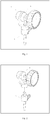
- Fig. 1 illustrates one exemplary embodiment of a mechanical device 1 (see Fig. 1 ) that can be inserted into the accessory port of an endoscope. As shown, the mechanical device 1 includes a control handle for conducting a multi-band ligation procedure.
- the mechanical device includes a rotating spool assembly 2 and a disposable valve assembly 3 (see Figs. 1-3 ).
- the rotating spool assembly 2 can be configured to be a re-usable element, wherein the components can be formed from specific materials (such as surgical grade stainless steel, titanium, or other metals) and assembled in such a way to enable sterilization and use with a plurality of patients.
- the disposable valve assembly 3 can include a mating stem member 4 (with an upper body 7), a sealing member 5, a flushing port member 6, and a tip 11.
- the upper body 7 of the mating stem member 4 includes tabs 15 (see Fig. 6 ). These elements are combined into an assembly that can be formed as a single disposable entity.
- the flushing port member 6 may have a luer taper, allowing fluid fittings to make leak-free connections between mating taper-fitting-parts.
- the means through which the disposable valve assembly 3 and rotating spool assembly 2 are attached can allow for rapid assembly and disassembly.
- attachment can be achieved via insertion and rotation of the disposable valve assembly 3 into the rotating spool assembly 2, for example using a quarter turn bayonet fitting (see Figs. 2 and 6 ).
- the disposable valve assembly 3 and the rotating spool assembly 2 may also be rigidly attached to each other through mechanical means so that the disposable valve assembly 3 and rotating spool assembly 2 are treated as a single entity and disposed of after single patient use (see Fig. 1 ).
- the mating stem member 4 can be shaped to mate with an endoscope accessory port.
- a taper on the insertion stem 8 can be provided to allow the tapered geometry to form a surface-to-surface mate with the internal geometry of an endoscope accessory port, upon insertion to an endoscope (see Figs. 4-5 ).
- the elongated portion above the tapered portion can also be engineered to be long enough so that it accommodates the height of all endoscopic caps currently on the market without detriment to the surface-to-surface mate with the internal geometry.
- the rotating spool assembly 2 can include a hub 16 with an arm 12. This enables the easy removal of the release cord 201 by counter-clockwise unravelling along the axis of the rotating spool 9 and provides an open design to increase access to the rotating spool assembly 2 (see Figs. 1 , 3 , and 17 ).
- the rotating spool assembly 2 features a hooking member 10 on the central rotating section of the spool 9.
- This hooking member 10 can mate to the loop member 209 of the release cord 201 of the multi-band ligation device and is an exemplary embodiment of the functionality which allows a multitude of different coupling methods to be utilized, if so desired (see Figs. 2 , 3 , and 17 ).
- the spool 9 can be rotated to draw the release cord 201 up through the working channel of the endoscope and wrap around the spool 9.
- the rotating spool assembly 2 can also include an end cap 17, a circlet 21, a washer 20, a clutch 13, O-rings 19, 18, a cylinder 14, and a receiver 16 (see Figs. 3 and 6 ).
- An alternate embodiment for attaching the release cord 201b to the spool 9b is for the spool 9b to incorporate a tapered toothed groove 10b such that, on drawing the release cord 201b into the groove, it is gripped and held securely (see Fig. 7 ).
- Another embodiment for attaching the release cord 201b to the spool 9c is for the spool 9c to incorporate two or more posts 10c such that wrapping the release cord around said posts 10c in a figure of eight causes the release cord 201b to be held by friction (see Fig. 8 ).
- Another embodiment for attaching the release cord 201b to the spool 9d is for the spool 9d to incorporate a single post 10d and the spool 9d a slot such that wrapping the cord 201b around the post 10d aligns the cord 201b and fitting the cord into the spool 9d slot retains the cord 201b (see Fig. 9 ).
- An accessory or instrument is also provided to be used in conjunction with a multi-band ligation device 1.
- This accessory is presently provided as a loading wire 101 that facilities the loading of the ligation band release cord, from the distal end of the working channel of a flexible endoscope to the proximal end of the working channel, until it exits through the accessory port of said endoscope, at which point the release cord may couple with the rotating spool of a multi-band ligation device handle (see Fig. 10 ).
- the loading wire 101 may be passed down the working channel from the accessory port to the distal end of the endoscope.
- the release cord 201 can be hooked on the loading wire 101, at which point the loading wire 101 can be withdrawn up the working channel.
- the release cord 201 can then be drawn up the working channel from the distal end to the proximal end attached to the loading wire.
- the simplicity of construction and manufacture of the loading wire 101 can be beneficial to the user.
- the loading wire 101 may be formed from a single piece of metallic wire that is post-formed to give it added functionally and improvements not seen in any similar devices.
- the metallic wire is post formed into a coiled shape 102 which adds benefits in terms of ease of handling and control for the operator. Because of the functionally of traveling through the working channel of endoscopes, the loading wire 101 needs to be very long, which can make handling and control of the loading wire 101 very difficult for the operator. By its very nature a coiled configuration 102 is much easier to handle and control and makes the process more manageable for the operator. Once the loading wire 101 is inserted into the endoscope working channel the coiled configuration 102 no longer becomes an issue as the loading wire 101 takes the shape of the working channel.
- the loading wire 101 On removal the loading wire 101 then returns to its coiled configuration 102, and this can present several safety benefits for the user.
- the coiled configuration can prevent the wire from jumping into the visual field of the user and/or assistant.
- the coiled configuration is also less likely to contact the floor or other unclean surfaces during the loading process.
- the loading wire is put down onto the small accessory tables and is needed to re-load the device for more band placements, it is much more likely to remain in place in a tight coil on the small accessory stand.
- the loading wire 101 incorporates straight sections 104 at the ends of the wire, to enable ease of entry into the endoscope working channel (see Fig. 10 ).
- the loading wire 101b could be formed as a complete coiled component without straight ends (see Fig. 11 ).
- a hook-like configuration 103 can be integrated on either or both ends of the loading wire 101 (see Fig. 12 ).
- the hook-like configuration 103 can be formed from the same single piece of wire, meaning any possibility of detachment of the hook component 103 is removed, which greatly adds to user confidence and increases patient safety.
- the hook-like configuration 103 can also be shaped to ensure that the possibility of the hook 103 catching on or snagging and damaging other medical equipment is drastically reduced given its low-profile design.
- the ends may also be formed into additional configurations (see Figs. 13-16 ).
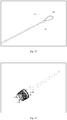
- the accessory is presently defined as a release cord 201 which facilitates the release of elastic ligation bands (see Fig. 17 ).
- the release cord 201 travels from the distal end of the working channel of a flexible endoscope to the proximal end of the working channel, until it exits through the accessory port of said endoscope at which point the release cord 201 may couple with the rotating spool 9 of a multi-band ligation device handle.
- the cord can also include beads 203-208 positioned in pairs, with one bead 203-208 on each filament 202, spaced at set intervals along the length of the single filament 202 (see Figs. 17-18 ).
- the pairs of beads 203-208 can be configured in a staggered and offset configuration, so the beads 203-208 are not positioned side-by-side (see Fig. 19 ). This means that, when the beads 203-208 are pulled inside the working channel, no two beads 203-208 will be side by side and occlude the working channel of the endoscope. The fact they are offset and staggered can reduce the possibility of the working channel becoming occluded. The more space that is available in the accessory channel during or after banding will increase the options for devices placed subsequently.
- Variously shaped beads may also be used (see Figs. 20-21 ).
- Ligation bands can be placed around the outside distal end of the endoscope in front of sets of the beads 203-208.
- the release cord 201 can be withdrawn up the working channel of the endoscope, which can cause the beads 203-208 to be withdrawn around the distal end of the endoscope.
- the ligation bands can be caused by the beads 203-208 to be pushed distally off of the distal end of the endoscope, thereby applying the band to the tissue drawn into the endoscope.
- a looped nature 209 to the proximal end of the release cord 201 (see Figs. 17 and 22 ). Having a closed loop configuration 209 at the proximal end of the cord 201 allows for a variety of attachment methods to any number of coupling modalities. It also ensures that these couplings will be safe and secure, which adds to operator confidence and results in better outcomes for patients through faster and more efficient procedures. These are procedures that are done in high stress conditions and in units where the light is usually very low in order to read the monitors involved.
Description
- The present disclosure relates generally to tissue ligation.
- Swollen and enlarged veins in the esophagus are commonly called esophageal varices. Esophageal varices have the potential to rupture and cause excessive bleeding in the esophagus, which can cause death in certain circumstances. Ligation of the varices can be performed to treat bleeding varices. Ligation can also be performed as a preventative measure to strangulate and remove the varices before they reach a stage where bleeding is a distinct risk. For ligation to be successfully performed through common practice, the varices must be pulled into a hollow chamber through suction, whereby elastic ligation bands are released over the tissue to strangulate it. Strangulation leads to death of the tissue and the subsequent natural detachment of the varices.
- Endoscopic hemorrhoid band ligation (HBL), similar in technique to the variceal banding described above is an important advancement in the treatment of symptomatic internal hemorrhoids (IH). Multiple rubber bands can be applied in one session, and further bands can be applied in subsequent sessions if a single session fails to completely eradicate the internal hemorrhoids. The treatment success rate is high, while the long-term recurrence rate is low. Symptomatic hemorrhoids in adults is considered one of the most prevalent anorectal disorders. Hemorrhoids of different grades can be found in more than 80%-90% of patients undergoing sigmoidoscopy or colonoscopy. Hemorrhoids are either internal or external depending on the localization above or below the dentate line.
- A new successful technique for the treatment of high grade dysplasia is endoscopic mucosal resection. This involves the piece-meal endoscopic resection of early neoplastic lesions larger than 15-20 mm. Before using band ligation, this was a laborious procedure. Multiband mucosectomy is a new safe and very effective technique using a modified variceal band ligator. Sub-mucosal lifting and pre-looping of the snare in the cap is not necessary and multiple resections can be performed with a single snare. The ligator suctions the targeted tissue into pseudo polyps and then the snare removes them in succession.
- For all three situations mentioned above, the ligation is performed in conjunction with an endoscope or other device that can be used to allow deep access to the human digestive tract. Endoscopes generally consist of a rigid or flexible tube with a working channel of varying internal diameters to allow a variety of medical instruments to be deployed and used in the human digestive tract. Endoscopes also feature a camera on the distal tip of the flexible tube to allow direct visualization of the digestive tract as well as light, suction and fluid delivery systems.
- Devices that facilitate this functionality are commonly called multi-band ligation devices. These devices consist of a hollow cylindrical barrel component which fits on the distal end of the endoscope, and that is configured to apply multiple bands over tissue suctioned into the device. There are many examples of multi-band ligation devices currently in use today. As well as this, a variety of instruments for effecting the ligation of body tissue by the application of an elastic band are known in the art in the form of single ligation band devices. Relevant prior art is disclosed in
US 6,007,551 A andUS 2014/081294 A1 . - Various methods and devices are provided for performing band ligation. In one aspect, an endoscopic surgical device has a rotating spool assembly and a valve assembly. The rotating spool assembly has a hub, an arm contiguous with the hub, and a rotating spool inserted through the arm. The hub has an opening formed therein. The valve assembly has a mating stem member, a sealing member, and a flushing port member. The mating stem member has a lumen extending through a longitudinal center thereof and has the sealing member extending thereacross. The lumen is aligned on a proximal end of the mating stem member with the opening in the rotating spool assembly. The valve assembly is coupled to a distal end of the rotating spool assembly.
- The endoscopic surgical device can vary in a variety of ways. For example, the rotating spool assembly can include a substantially hook-shaped member that rotates as one with the spool, the substantially hook-shaped member being configured to receive a cable. As another example, the spool can comprise a tapered toothed groove sized to grip a release cord. In another example, the spool can include first and second posts protruding from a surface thereof and positioned next to one another. The first and second posts can be configured to receive a cable therearound. In another embodiment, the spool can comprise at least one post protruding from a surface thereof and a groove in the surface positioned proximally from the post. As another example, the mating stem member can include an upper body with one or more tabs formed on the upper body. The mating stem member can also include a tapered section at a distal end thereof, and the tapered section can be shaped to be inserted into an auxiliary port of an endoscope to form a surface-to-surface mating engagement with a corresponding internal geometry of the auxiliary port. As another example, the rotating spool assembly can couple to the valve assembly using a quarter turn bayonet fitting.
- In another aspect, an endoscopic surgical device is provided that has a spool assembly and a loading wire. The spool assembly has a rotating member and a stem having a lumen extending therethrough. The loading wire extends through the lumen in the stem of the spool assembly. The loading wire also has a proximal end extending proximally from the lumen in the stem toward and has a distal end extending distally from the lumen in the stem. The distal end of the loading wire has a hook formed thereon and is configured to couple to a thread such that the proximal end of the loading wire can be pulled proximally to pull the thread through the spool assembly.
- The endoscopic surgical device can be varied in a variety of ways. For example, the loading wire can be formed from metal drawn out into a thin flexible thread. As another example, the loading wire can form one or more coils. The coils can constrain the wire in a coiled configuration in a first position when the wire is separated from the spool assembly, and the wire can conform to a longitudinal shape of the lumen in a second position when the wire is disposed through the lumen. In another embodiment, the proximal end of the loading wire includes a hook formed thereon. In another example, the hooks can be formed from the wire being turned back upon itself to form a hook shape, and a central axis of a distal end of each hook can be co-linear with a central axis of the wire. The loading member can also be formed from a braiding of two or more single wires. As another example, the loading member can be formed from a polymer. A central segment of the wire can also form one or more coils, and proximal and distal portions of the wire can be formed of straight sections.
- In another aspect, a release cord is provided with a braided cord and a plurality of beads. The braided cord has first and second single filaments. The single filaments are braided together at a proximal end of the braided cord and separated at a distal end of the braided cord. The plurality of beads are formed along a length of each of the first and second single filaments at the distal end of the braided cord. The plurality of beads are positioned such that no two beads are at a same distance from the proximal end of the braided cord.
- The release cord can be varied in a variety of ways. For example, the beads can be substantially spherical. The beads can also be made of a polymer. In another example, a proximal section of the release cord can be formed into a closed loop configuration, and the closed looped configuration can be sized to fit through a working channel of an endoscope. In another example, the closed looped configuration at the proximal end can be created by attaching a separate closed loop shaped component through mechanical means.
- In another aspect, a system for tissue ligation is provided with a rotating spool assembly, a valve assembly, a wire, and a release cord. The rotating spool assembly has a hub and a spool, with an opening being formed in the hub. The valve assembly has a mating stem member. A lumen extends through a longitudinal center of the mating stem member and aligns on a proximal end of the mating stem member with the opening in the rotating spool assembly. The valve assembly is coupled to a distal end of the rotating spool assembly. The wire has a cross sectional dimension that does not exceed the lumen of the valve assembly, and hooks are formed on each end of the wire. The release cord has a braided cord with first and second single filaments. The single filaments are braided together at a proximal end of the braided cord and separated at a distal end of the braided cord. A plurality of beads are formed along a length of each of the first and second single filaments at the distal end of the braided cord.
- The system can vary in any number of ways. For example, the plurality of beads can be positioned such that no two beads are at a same distance from the proximal end of the braided cord. As another example, the spool can have a substantially hook-shaped member on a surface thereof, and a proximal end of the release cord can be attached to the substantially hook-shaped member.
- As another aspect, a method for assisting with tissue ligation is provided. The method includes passing a loading member having a wire with a hook formed on at least a distal end through an opening in a rotating spool assembly having a spool, distally along a lumen formed in a valve assembly coupled to the rotating spool assembly, and distally along a length of a working channel of an endoscope such that the hook protrudes from a distal end of the working channel. The method also includes securing a proximal end of a release cord onto the hook. The release cord has a braided cord with at least two single filaments, and the single filaments are separated at a distal end of the braided cord and having a plurality of beads formed along a distal length of each of the single filaments. The method additionally includes drawing the proximal end of the release cord proximally through the working channel, the valve assembly, and the rotating spool assembly until the proximal end of the release cord protrudes from a proximal end of the rotating spool assembly. The method further includes attaching the proximal end of the release cord to the spool of the rotating spool assembly.
- The method can vary in any number of ways. For example, the plurality of beads on the single filaments of the release cord can be positioned such that no two beads are at a same distance from the proximal end of the braided cord. The method can also further include wrapping a plurality of ligation bands around an outside distal surface of the endoscope, with each ligation band being positioned in front of corresponding sets of beads on each of the single filaments. As another example, the method can include positioning a distal end of the endoscope against a tissue to be ligated, and retracting the release cord proximally by rotating the spool such that one ligation band is applied to the tissue as the corresponding beads on each single filament are withdrawn into the working channel of the endoscope.
- This invention will be more fully understood from the following detailed description taken in conjunction with the accompanying drawings, in which:
-
FIG. 1 shows an embodiment of a mechanical device. -
FIG. 2 shows an embodiment of a mechanical device. -
FIG. 3 shows an exploded view of an embodiment of a rotating spool assembly. -
FIG. 4 shows an exploded view of an embodiment of a disposable valve assembly. -
FIG. 5 shows an embodiment of a mechanical device in operation with an endoscope. -
FIG. 6 shows an embodiment of a mechanical device. -
FIGS. 7-9 show embodiments of a mechanical device with a spool. -
FIGS. 10-16 show embodiments of an accessory. -
FIGS. 17-21 show an embodiment of a second accessory. -
FIG. 22 shows an embodiment of a release cord. -
FIGS. 23-24 show examples of multi-band ligation devices. - Certain exemplary embodiments will now be described to provide an overall understanding of the principles of the structure, function, manufacture, and use of the devices and methods disclosed herein. One or more examples of these embodiments are illustrated in the accompanying drawings. Those skilled in the art will understand that the devices and methods specifically described herein and illustrated in the accompanying drawings are nonlimiting exemplary embodiments and that the scope of the present invention is defined solely by the claims. The features illustrated or described in connection with one exemplary embodiment may be combined with the features of other embodiments. Such modifications and variations are intended to be included within the scope of the present disclosure.
- Further, in the present disclosure, like-named components of the embodiments generally have similar features, and thus within a particular embodiment each feature of each like-named component is not necessarily fully elaborated upon. Additionally, to the extent that linear or circular dimensions are used in the description of the disclosed systems, devices, and methods, such dimensions are not intended to limit the types of shapes that can be used in conjunction with such systems, devices, and methods. A person skilled in the art will recognize that an equivalent to such linear and circular dimensions can easily be determined for any geometric shape. Sizes and shapes of the systems and devices, and the components thereof, can depend at least on the anatomy of the subject in which the systems and devices will be used, the size and shape of components with which the systems and devices will be used, and the methods and procedures in which the systems and devices will be used.
- In general, a mechanical device for coupling to an access device, such as an endoscope, is provided. The mechanical device can be provided as an add-on kit for attachment to an endoscope or other access device just prior to or during surgery, and the mechanical device can be configured to apply one or more ligation bands to tissue to be ligated.
Fig. 1 illustrates one exemplary embodiment of a mechanical device 1 (seeFig. 1 ) that can be inserted into the accessory port of an endoscope. As shown, themechanical device 1 includes a control handle for conducting a multi-band ligation procedure. - In one embodiment, the mechanical device includes a
rotating spool assembly 2 and a disposable valve assembly 3 (seeFigs. 1-3 ). Therotating spool assembly 2 can be configured to be a re-usable element, wherein the components can be formed from specific materials (such as surgical grade stainless steel, titanium, or other metals) and assembled in such a way to enable sterilization and use with a plurality of patients. Thedisposable valve assembly 3 can include a mating stem member 4 (with an upper body 7), a sealingmember 5, a flushing port member 6, and atip 11. Theupper body 7 of the mating stem member 4 includes tabs 15 (seeFig. 6 ). These elements are combined into an assembly that can be formed as a single disposable entity. The flushing port member 6 may have a luer taper, allowing fluid fittings to make leak-free connections between mating taper-fitting-parts. - The means through which the
disposable valve assembly 3 androtating spool assembly 2 are attached can allow for rapid assembly and disassembly. In an exemplary embodiment, attachment can be achieved via insertion and rotation of thedisposable valve assembly 3 into therotating spool assembly 2, for example using a quarter turn bayonet fitting (seeFigs. 2 and6 ). - The
disposable valve assembly 3 and therotating spool assembly 2 may also be rigidly attached to each other through mechanical means so that thedisposable valve assembly 3 androtating spool assembly 2 are treated as a single entity and disposed of after single patient use (seeFig. 1 ). - Also provided herein is a mating stem member 4. The mating stem member 4 can be shaped to mate with an endoscope accessory port. For example, a taper on the insertion stem 8 can be provided to allow the tapered geometry to form a surface-to-surface mate with the internal geometry of an endoscope accessory port, upon insertion to an endoscope (see
Figs. 4-5 ). The elongated portion above the tapered portion can also be engineered to be long enough so that it accommodates the height of all endoscopic caps currently on the market without detriment to the surface-to-surface mate with the internal geometry. - The
rotating spool assembly 2 can include a hub 16 with anarm 12. This enables the easy removal of therelease cord 201 by counter-clockwise unravelling along the axis of the rotating spool 9 and provides an open design to increase access to the rotating spool assembly 2 (seeFigs. 1 ,3 , and17 ). - In an exemplary embodiment, the rotating
spool assembly 2 features a hooking member 10 on the central rotating section of the spool 9. This hooking member 10 can mate to theloop member 209 of therelease cord 201 of the multi-band ligation device and is an exemplary embodiment of the functionality which allows a multitude of different coupling methods to be utilized, if so desired (seeFigs. 2 ,3 , and17 ). The spool 9 can be rotated to draw therelease cord 201 up through the working channel of the endoscope and wrap around the spool 9. Therotating spool assembly 2 can also include an end cap 17, a circlet 21, awasher 20, a clutch 13, O-rings Figs. 3 and6 ). - An alternate embodiment for attaching the
release cord 201b to thespool 9b is for thespool 9b to incorporate a taperedtoothed groove 10b such that, on drawing therelease cord 201b into the groove, it is gripped and held securely (seeFig. 7 ). - Another embodiment for attaching the
release cord 201b to thespool 9c is for thespool 9c to incorporate two or more posts 10c such that wrapping the release cord around said posts 10c in a figure of eight causes therelease cord 201b to be held by friction (seeFig. 8 ). - Another embodiment for attaching the
release cord 201b to thespool 9d is for thespool 9d to incorporate asingle post 10d and thespool 9d a slot such that wrapping thecord 201b around thepost 10d aligns thecord 201b and fitting the cord into thespool 9d slot retains thecord 201b (seeFig. 9 ). - An accessory or instrument is also provided to be used in conjunction with a
multi-band ligation device 1. This accessory is presently provided as aloading wire 101 that facilities the loading of the ligation band release cord, from the distal end of the working channel of a flexible endoscope to the proximal end of the working channel, until it exits through the accessory port of said endoscope, at which point the release cord may couple with the rotating spool of a multi-band ligation device handle (seeFig. 10 ). Theloading wire 101 may be passed down the working channel from the accessory port to the distal end of the endoscope. Therelease cord 201 can be hooked on theloading wire 101, at which point theloading wire 101 can be withdrawn up the working channel. Therelease cord 201 can then be drawn up the working channel from the distal end to the proximal end attached to the loading wire. - The simplicity of construction and manufacture of the
loading wire 101 can be beneficial to the user. Theloading wire 101 may be formed from a single piece of metallic wire that is post-formed to give it added functionally and improvements not seen in any similar devices. - One advantage is the coiled
configuration 102 of the wire (seeFigs. 10-11 ). The metallic wire is post formed into acoiled shape 102 which adds benefits in terms of ease of handling and control for the operator. Because of the functionally of traveling through the working channel of endoscopes, theloading wire 101 needs to be very long, which can make handling and control of theloading wire 101 very difficult for the operator. By its very nature acoiled configuration 102 is much easier to handle and control and makes the process more manageable for the operator. Once theloading wire 101 is inserted into the endoscope working channel the coiledconfiguration 102 no longer becomes an issue as theloading wire 101 takes the shape of the working channel. On removal theloading wire 101 then returns to itscoiled configuration 102, and this can present several safety benefits for the user. For example, the coiled configuration can prevent the wire from jumping into the visual field of the user and/or assistant. The coiled configuration is also less likely to contact the floor or other unclean surfaces during the loading process. Finally, if the loading wire is put down onto the small accessory tables and is needed to re-load the device for more band placements, it is much more likely to remain in place in a tight coil on the small accessory stand. - In an exemplary embodiment, the
loading wire 101 incorporates straight sections 104 at the ends of the wire, to enable ease of entry into the endoscope working channel (seeFig. 10 ). Alternately the loading wire 101b could be formed as a complete coiled component without straight ends (seeFig. 11 ). - A hook-
like configuration 103 can be integrated on either or both ends of the loading wire 101 (seeFig. 12 ). The hook-like configuration 103 can be formed from the same single piece of wire, meaning any possibility of detachment of thehook component 103 is removed, which greatly adds to user confidence and increases patient safety. The hook-like configuration 103 can also be shaped to ensure that the possibility of thehook 103 catching on or snagging and damaging other medical equipment is drastically reduced given its low-profile design. The ends may also be formed into additional configurations (seeFigs. 13-16 ). - There is also a secondary accessory or instrument to be used in conjunction with a
multi-band ligation device 1. The accessory is presently defined as arelease cord 201 which facilitates the release of elastic ligation bands (seeFig. 17 ). Therelease cord 201 travels from the distal end of the working channel of a flexible endoscope to the proximal end of the working channel, until it exits through the accessory port of said endoscope at which point therelease cord 201 may couple with the rotating spool 9 of a multi-band ligation device handle. - The cord can also include beads 203-208 positioned in pairs, with one bead 203-208 on each filament 202, spaced at set intervals along the length of the single filament 202 (see
Figs. 17-18 ). The pairs of beads 203-208 can be configured in a staggered and offset configuration, so the beads 203-208 are not positioned side-by-side (seeFig. 19 ). This means that, when the beads 203-208 are pulled inside the working channel, no two beads 203-208 will be side by side and occlude the working channel of the endoscope. The fact they are offset and staggered can reduce the possibility of the working channel becoming occluded. The more space that is available in the accessory channel during or after banding will increase the options for devices placed subsequently. Variously shaped beads may also be used (seeFigs. 20-21 ). - Ligation bands can be placed around the outside distal end of the endoscope in front of sets of the beads 203-208. The
release cord 201 can be withdrawn up the working channel of the endoscope, which can cause the beads 203-208 to be withdrawn around the distal end of the endoscope. The ligation bands can be caused by the beads 203-208 to be pushed distally off of the distal end of the endoscope, thereby applying the band to the tissue drawn into the endoscope. - In one embodiment, there is a looped
nature 209 to the proximal end of the release cord 201 (seeFigs. 17 and22 ). Having aclosed loop configuration 209 at the proximal end of thecord 201 allows for a variety of attachment methods to any number of coupling modalities. It also ensures that these couplings will be safe and secure, which adds to operator confidence and results in better outcomes for patients through faster and more efficient procedures. These are procedures that are done in high stress conditions and in units where the light is usually very low in order to read the monitors involved. - One skilled in the art will appreciate further features and advantages of the invention based on the above-described embodiments. Accordingly, the invention is not to be limited by what has been particularly shown and described, except as indicated by the appended claims.
Claims (11)
- An endoscopic surgical device, comprising:a rotating spool assembly having a hub, an arm contiguous with the hub, and a rotating spool inserted through the arm, the hub having an opening formed therein;a valve assembly having a mating stem member, a sealing member, and a flushing port member, the mating stem member having a lumen extending through a longitudinal center thereof and having the sealing member extending thereacross, the lumen being aligned on a proximal end of the mating stem member with the opening in the rotating spool assembly, and the valve assembly being coupled to a distal end of the rotating spool assembly; characterised bya braided cord having first and second single filaments, the single filaments being braided together at a proximal end of the braided cord and separated at a distal end of the braided cord, the proximal end of the braided cord being configured to attach to the rotating spool, the distal end of the braided cord being configured to pass through the lumen of the mating stem member, a plurality of beads being formed along a length of each of the first and second single filaments at the distal end of the braided cord, the plurality of beads being positioned such that no two beads are at a same distance from the proximal end of the braided cord.
- The device of claim 1, wherein the rotating spool assembly comprises (a) a substantially hook-shaped member that rotates as one with the spool, the substantially hook-shaped member being configured to receive the braided cord; (b) a tapered toothed groove sized to grip the braided cord; (c) first and second posts protruding from a surface thereof and positioned next to one another, the first and second posts being configured to receive the braided cord therearound; and/or (d) at least one post protruding from a surface thereof and a groove in the surface positioned proximally from the post.
- The device of claim 1, wherein the mating stem member includes (a) an upper body with one or more tabs formed on the upper body; and/or (b) a tapered section at a distal end thereof, and the tapered section is shaped to be inserted into an auxiliary port of an endoscope to form a surface-to-surface mating engagement with a corresponding internal geometry of the auxiliary port.
- The device of claim 1, wherein the rotating spool assembly couples to the valve assembly using a quarter turn bayonet fitting.
- The device of claim 1, further comprising: a loading wire being configured to extend through the lumen in the mating stem member and having a proximal end extending proximally from the lumen in the mating stem member toward and having a distal end extending distally from the lumen in the mating stem member, the distal end having a hook formed thereon and configured to couple to the braided cord such that the proximal end of the loading wire can be pulled proximally to pull the braided cord through the spool assembly.
- The device of claim 5, wherein the loading wire is formed from metal drawn out into a thin flexible thread and/or wherein the loading wire forms one or more coils, the coils constraining the wire in a coiled configuration in a first position when the wire is separated from the spool assembly, and the wire conforming to a longitudinal shape of the lumen in a second position when the wire is disposed through the lumen.
- The device of claim 5, wherein the proximal end of the loading wire includes a hook formed thereon and optionally wherein the hooks are formed from the wire being turned back upon itself to form a hook shape, and a central axis of a distal end of each hook is co-linear with a central axis of the wire.
- The device of claim 5, wherein the loading member is formed from a braiding of two or more single wires and /or wherein the loading member is formed from a polymer.
- The device of claim 5, wherein a central segment of the wire forms one or more coils, and proximal and distal portions of the wire are formed of straight sections.
- The device of claim 1, wherein the beads are substantially spherical and/or wherein the beads are made of a polymer.
- The device of claim 1, wherein a proximal section of the release cord is formed into a closed loop configuration, and the closed looped configuration is sized to fit through a working channel of an endoscope, optionally wherein the closed looped configuration at the proximal end is created by attaching a separate closed loop shaped component through mechanical means.
Applications Claiming Priority (2)
| Application Number | Priority Date | Filing Date | Title |
|---|---|---|---|
| US201462085272P | 2014-11-27 | 2014-11-27 | |
| PCT/US2015/062462 WO2016086003A1 (en) | 2014-11-27 | 2015-11-24 | Tissue ligation apparatus with a rotating spool assembly and a valve assembly |
Publications (3)
| Publication Number | Publication Date |
|---|---|
| EP3223720A1 EP3223720A1 (en) | 2017-10-04 |
| EP3223720A4 EP3223720A4 (en) | 2018-08-01 |
| EP3223720B1 true EP3223720B1 (en) | 2021-07-07 |
Family
ID=56074982
Family Applications (1)
| Application Number | Title | Priority Date | Filing Date |
|---|---|---|---|
| EP15862863.6A Active EP3223720B1 (en) | 2014-11-27 | 2015-11-24 | Tissue ligation apparatus with a rotating spool assembly and a valve assembly |
Country Status (3)
| Country | Link |
|---|---|
| US (1) | US10820905B2 (en) |
| EP (1) | EP3223720B1 (en) |
| WO (1) | WO2016086003A1 (en) |
Families Citing this family (7)
| Publication number | Priority date | Publication date | Assignee | Title |
|---|---|---|---|---|
| EP3223720B1 (en) | 2014-11-27 | 2021-07-07 | Intelligent Endoscopy LLC | Tissue ligation apparatus with a rotating spool assembly and a valve assembly |
| US10690849B2 (en) | 2016-06-06 | 2020-06-23 | The Trustees Of Columbia University In The City Of New York | Integrated micro-lens waveguide and methods of making and using same |
| US10703150B2 (en) * | 2017-09-11 | 2020-07-07 | Fred P. Smith | Adjustable safety chain attachment for trailers |
| EP3742985A4 (en) * | 2018-01-26 | 2021-10-27 | Intelligent Endoscopy LLC | Anti-slip bands |
| EP3773253B1 (en) | 2018-03-30 | 2023-03-22 | United States Endoscopy Group, Inc. | Criss-cross cords for band ligation |
| JP7451866B2 (en) | 2019-02-12 | 2024-03-19 | ユナイテッド ステイツ エンドスコピー グループ,インコーポレイテッド | Loading the band ligation |
| CN112451026B (en) * | 2020-12-07 | 2021-10-08 | 咸宁市中心医院 | Compression device for puncture interventional operation |
Family Cites Families (16)
| Publication number | Priority date | Publication date | Assignee | Title |
|---|---|---|---|---|
| DE4133966C1 (en) * | 1991-10-14 | 1993-04-29 | Richard Wolf Gmbh, 7134 Knittlingen, De | |
| US5624453A (en) * | 1993-02-23 | 1997-04-29 | Wilson-Cook Medical, Inc. | Endoscopic ligating instrument |
| US6007551A (en) | 1993-02-23 | 1999-12-28 | Wilson-Cook Medical Inc. | Endoscopic ligating apparatus |
| US6685713B1 (en) | 1993-02-22 | 2004-02-03 | Dabegran Technologies, Inc. | Endoscopic ligating apparatus |
| US5398844A (en) * | 1994-01-31 | 1995-03-21 | Boston Scientific Corporation | Multiple ligating band dispenser |
| US5695491A (en) * | 1994-11-22 | 1997-12-09 | Washington Research Foundation | Endoscopic accessory and containment system |
| US5968056A (en) * | 1997-11-13 | 1999-10-19 | Boston Scientific Corporation | Device and method for severing lesions |
| US6235040B1 (en) * | 1998-09-21 | 2001-05-22 | Scimed Life Systems, Inc. | Single pull wire multiple band ligator |
| WO2001087226A2 (en) * | 2000-05-18 | 2001-11-22 | Wilson-Cook Medical Inc. | Percutaneous gastrostomy device and method |
| JP4578632B2 (en) | 2000-07-05 | 2010-11-10 | オリンパス株式会社 | Endoscopic instrument |
| US20060212042A1 (en) * | 2005-03-17 | 2006-09-21 | Lamport Ronald B | Removal and repositioning device |
| US8845516B2 (en) * | 2005-05-09 | 2014-09-30 | Endochoice, Inc. | Ligator |
| EP2136719B1 (en) | 2007-04-13 | 2018-08-29 | Cook Medical Technologies LLC | Endoscopic barrel with connector |
| US10285747B2 (en) * | 2008-06-18 | 2019-05-14 | Alphatec Spine, Inc. | Implant deployment system and methods of use |
| CA2884262A1 (en) | 2012-09-14 | 2014-03-20 | Alpine Medical Devices, Llc | Ligator and method of use |
| EP3223720B1 (en) | 2014-11-27 | 2021-07-07 | Intelligent Endoscopy LLC | Tissue ligation apparatus with a rotating spool assembly and a valve assembly |
-
2015
- 2015-11-24 EP EP15862863.6A patent/EP3223720B1/en active Active
- 2015-11-24 US US15/527,830 patent/US10820905B2/en active Active
- 2015-11-24 WO PCT/US2015/062462 patent/WO2016086003A1/en active Application Filing
Also Published As
| Publication number | Publication date |
|---|---|
| EP3223720A4 (en) | 2018-08-01 |
| US10820905B2 (en) | 2020-11-03 |
| EP3223720A1 (en) | 2017-10-04 |
| US20170303930A1 (en) | 2017-10-26 |
| WO2016086003A1 (en) | 2016-06-02 |
Similar Documents
| Publication | Publication Date | Title |
|---|---|---|
| EP3223720B1 (en) | Tissue ligation apparatus with a rotating spool assembly and a valve assembly | |
| US10702273B2 (en) | Ligator and method of use | |
| JP3573751B2 (en) | Endoscopic ligation device | |
| US8506477B2 (en) | System and method for endoscopic treatment of tissue | |
| US20060089660A1 (en) | System and method for endoscopic treatment of tissue | |
| JP5498935B2 (en) | Endoscope fixation system | |
| EP3366236B1 (en) | Ligation device | |
| EP0858291A1 (en) | Endoscopic ligating instrument | |
| CN114144127A (en) | Systems, devices, and methods for treating hemorrhoids | |
| US20080287965A1 (en) | Radiopaque band ligator | |
| JP2022541666A (en) | Device for closing wounds | |
| US9795386B2 (en) | Multiple band endoscopic ligation device | |
| JP2023116814A (en) | Traction systems and methods of use thereof for endoscopic procedures | |
| CA2682293C (en) | Endoscopic suction device for mucosectomy | |
| CN114126510A (en) | Device and method for examining and treating hemorrhoids | |
| JP2024504400A (en) | Repositionable clip with extension | |
| US11957351B2 (en) | Tissue ligation systems and methods of ligating tissue | |
| CN212490038U (en) | Ligation device | |
| JP2000102542A (en) | Ligating instrument for endoscope | |
| WO2023022811A1 (en) | Over the scope clip with compliant mechanism | |
| JP2024056976A (en) | Tissue retraction devices, systems and methods | |
| CN111466989A (en) | Ligation device |
Legal Events
| Date | Code | Title | Description |
|---|---|---|---|
| STAA | Information on the status of an ep patent application or granted ep patent |
Free format text: STATUS: THE INTERNATIONAL PUBLICATION HAS BEEN MADE |
|
| PUAI | Public reference made under article 153(3) epc to a published international application that has entered the european phase |
Free format text: ORIGINAL CODE: 0009012 |
|
| STAA | Information on the status of an ep patent application or granted ep patent |
Free format text: STATUS: REQUEST FOR EXAMINATION WAS MADE |
|
| 17P | Request for examination filed |
Effective date: 20170626 |
|
| AK | Designated contracting states |
Kind code of ref document: A1 Designated state(s): AL AT BE BG CH CY CZ DE DK EE ES FI FR GB GR HR HU IE IS IT LI LT LU LV MC MK MT NL NO PL PT RO RS SE SI SK SM TR |
|
| AX | Request for extension of the european patent |
Extension state: BA ME |
|
| DAV | Request for validation of the european patent (deleted) | ||
| DAX | Request for extension of the european patent (deleted) | ||
| A4 | Supplementary search report drawn up and despatched |
Effective date: 20180629 |
|
| RIC1 | Information provided on ipc code assigned before grant |
Ipc: A61B 17/00 20060101ALI20180625BHEP Ipc: A61B 17/12 20060101AFI20180625BHEP |
|
| GRAP | Despatch of communication of intention to grant a patent |
Free format text: ORIGINAL CODE: EPIDOSNIGR1 |
|
| STAA | Information on the status of an ep patent application or granted ep patent |
Free format text: STATUS: GRANT OF PATENT IS INTENDED |
|
| INTG | Intention to grant announced |
Effective date: 20210115 |
|
| GRAS | Grant fee paid |
Free format text: ORIGINAL CODE: EPIDOSNIGR3 |
|
| GRAA | (expected) grant |
Free format text: ORIGINAL CODE: 0009210 |
|
| STAA | Information on the status of an ep patent application or granted ep patent |
Free format text: STATUS: THE PATENT HAS BEEN GRANTED |
|
| AK | Designated contracting states |
Kind code of ref document: B1 Designated state(s): AL AT BE BG CH CY CZ DE DK EE ES FI FR GB GR HR HU IE IS IT LI LT LU LV MC MK MT NL NO PL PT RO RS SE SI SK SM TR |
|
| REG | Reference to a national code |
Ref country code: GB Ref legal event code: FG4D |
|
| REG | Reference to a national code |
Ref country code: AT Ref legal event code: REF Ref document number: 1407797 Country of ref document: AT Kind code of ref document: T Effective date: 20210715 |
|
| REG | Reference to a national code |
Ref country code: DE Ref legal event code: R096 Ref document number: 602015071186 Country of ref document: DE |
|
| REG | Reference to a national code |
Ref country code: IE Ref legal event code: FG4D |
|
| REG | Reference to a national code |
Ref country code: DE Ref legal event code: R081 Ref document number: 602015071186 Country of ref document: DE Owner name: UNITED STATES ENDOSCOPY GROUP, INC., MENTOR, US Free format text: FORMER OWNER: INTELLIGENT ENDOSCOPY LLC, CLEMMONS, NC, US |
|
| REG | Reference to a national code |
Ref country code: LT Ref legal event code: MG9D |
|
| REG | Reference to a national code |
Ref country code: GB Ref legal event code: 732E Free format text: REGISTERED BETWEEN 20211007 AND 20211013 |
|
| REG | Reference to a national code |
Ref country code: NL Ref legal event code: MP Effective date: 20210707 |
|
| REG | Reference to a national code |
Ref country code: AT Ref legal event code: MK05 Ref document number: 1407797 Country of ref document: AT Kind code of ref document: T Effective date: 20210707 |
|
| PG25 | Lapsed in a contracting state [announced via postgrant information from national office to epo] |
Ref country code: AT Free format text: LAPSE BECAUSE OF FAILURE TO SUBMIT A TRANSLATION OF THE DESCRIPTION OR TO PAY THE FEE WITHIN THE PRESCRIBED TIME-LIMIT Effective date: 20210707 Ref country code: BG Free format text: LAPSE BECAUSE OF FAILURE TO SUBMIT A TRANSLATION OF THE DESCRIPTION OR TO PAY THE FEE WITHIN THE PRESCRIBED TIME-LIMIT Effective date: 20211007 Ref country code: LT Free format text: LAPSE BECAUSE OF FAILURE TO SUBMIT A TRANSLATION OF THE DESCRIPTION OR TO PAY THE FEE WITHIN THE PRESCRIBED TIME-LIMIT Effective date: 20210707 Ref country code: NO Free format text: LAPSE BECAUSE OF FAILURE TO SUBMIT A TRANSLATION OF THE DESCRIPTION OR TO PAY THE FEE WITHIN THE PRESCRIBED TIME-LIMIT Effective date: 20211007 Ref country code: NL Free format text: LAPSE BECAUSE OF FAILURE TO SUBMIT A TRANSLATION OF THE DESCRIPTION OR TO PAY THE FEE WITHIN THE PRESCRIBED TIME-LIMIT Effective date: 20210707 Ref country code: PT Free format text: LAPSE BECAUSE OF FAILURE TO SUBMIT A TRANSLATION OF THE DESCRIPTION OR TO PAY THE FEE WITHIN THE PRESCRIBED TIME-LIMIT Effective date: 20211108 Ref country code: FI Free format text: LAPSE BECAUSE OF FAILURE TO SUBMIT A TRANSLATION OF THE DESCRIPTION OR TO PAY THE FEE WITHIN THE PRESCRIBED TIME-LIMIT Effective date: 20210707 Ref country code: ES Free format text: LAPSE BECAUSE OF FAILURE TO SUBMIT A TRANSLATION OF THE DESCRIPTION OR TO PAY THE FEE WITHIN THE PRESCRIBED TIME-LIMIT Effective date: 20210707 Ref country code: HR Free format text: LAPSE BECAUSE OF FAILURE TO SUBMIT A TRANSLATION OF THE DESCRIPTION OR TO PAY THE FEE WITHIN THE PRESCRIBED TIME-LIMIT Effective date: 20210707 Ref country code: RS Free format text: LAPSE BECAUSE OF FAILURE TO SUBMIT A TRANSLATION OF THE DESCRIPTION OR TO PAY THE FEE WITHIN THE PRESCRIBED TIME-LIMIT Effective date: 20210707 Ref country code: SE Free format text: LAPSE BECAUSE OF FAILURE TO SUBMIT A TRANSLATION OF THE DESCRIPTION OR TO PAY THE FEE WITHIN THE PRESCRIBED TIME-LIMIT Effective date: 20210707 |
|
| PG25 | Lapsed in a contracting state [announced via postgrant information from national office to epo] |
Ref country code: PL Free format text: LAPSE BECAUSE OF FAILURE TO SUBMIT A TRANSLATION OF THE DESCRIPTION OR TO PAY THE FEE WITHIN THE PRESCRIBED TIME-LIMIT Effective date: 20210707 Ref country code: LV Free format text: LAPSE BECAUSE OF FAILURE TO SUBMIT A TRANSLATION OF THE DESCRIPTION OR TO PAY THE FEE WITHIN THE PRESCRIBED TIME-LIMIT Effective date: 20210707 Ref country code: GR Free format text: LAPSE BECAUSE OF FAILURE TO SUBMIT A TRANSLATION OF THE DESCRIPTION OR TO PAY THE FEE WITHIN THE PRESCRIBED TIME-LIMIT Effective date: 20211008 |
|
| RAP2 | Party data changed (patent owner data changed or rights of a patent transferred) |
Owner name: UNITED STATES ENDOSCOPY GROUP, INC. |
|
| REG | Reference to a national code |
Ref country code: DE Ref legal event code: R097 Ref document number: 602015071186 Country of ref document: DE |
|
| PG25 | Lapsed in a contracting state [announced via postgrant information from national office to epo] |
Ref country code: DK Free format text: LAPSE BECAUSE OF FAILURE TO SUBMIT A TRANSLATION OF THE DESCRIPTION OR TO PAY THE FEE WITHIN THE PRESCRIBED TIME-LIMIT Effective date: 20210707 |
|
| PLBE | No opposition filed within time limit |
Free format text: ORIGINAL CODE: 0009261 |
|
| STAA | Information on the status of an ep patent application or granted ep patent |
Free format text: STATUS: NO OPPOSITION FILED WITHIN TIME LIMIT |
|
| PG25 | Lapsed in a contracting state [announced via postgrant information from national office to epo] |
Ref country code: SM Free format text: LAPSE BECAUSE OF FAILURE TO SUBMIT A TRANSLATION OF THE DESCRIPTION OR TO PAY THE FEE WITHIN THE PRESCRIBED TIME-LIMIT Effective date: 20210707 Ref country code: SK Free format text: LAPSE BECAUSE OF FAILURE TO SUBMIT A TRANSLATION OF THE DESCRIPTION OR TO PAY THE FEE WITHIN THE PRESCRIBED TIME-LIMIT Effective date: 20210707 Ref country code: RO Free format text: LAPSE BECAUSE OF FAILURE TO SUBMIT A TRANSLATION OF THE DESCRIPTION OR TO PAY THE FEE WITHIN THE PRESCRIBED TIME-LIMIT Effective date: 20210707 Ref country code: EE Free format text: LAPSE BECAUSE OF FAILURE TO SUBMIT A TRANSLATION OF THE DESCRIPTION OR TO PAY THE FEE WITHIN THE PRESCRIBED TIME-LIMIT Effective date: 20210707 Ref country code: CZ Free format text: LAPSE BECAUSE OF FAILURE TO SUBMIT A TRANSLATION OF THE DESCRIPTION OR TO PAY THE FEE WITHIN THE PRESCRIBED TIME-LIMIT Effective date: 20210707 Ref country code: AL Free format text: LAPSE BECAUSE OF FAILURE TO SUBMIT A TRANSLATION OF THE DESCRIPTION OR TO PAY THE FEE WITHIN THE PRESCRIBED TIME-LIMIT Effective date: 20210707 |
|
| 26N | No opposition filed |
Effective date: 20220408 |
|
| PG25 | Lapsed in a contracting state [announced via postgrant information from national office to epo] |
Ref country code: MC Free format text: LAPSE BECAUSE OF FAILURE TO SUBMIT A TRANSLATION OF THE DESCRIPTION OR TO PAY THE FEE WITHIN THE PRESCRIBED TIME-LIMIT Effective date: 20210707 |
|
| REG | Reference to a national code |
Ref country code: CH Ref legal event code: PL |
|
| PG25 | Lapsed in a contracting state [announced via postgrant information from national office to epo] |
Ref country code: LU Free format text: LAPSE BECAUSE OF NON-PAYMENT OF DUE FEES Effective date: 20211124 Ref country code: BE Free format text: LAPSE BECAUSE OF NON-PAYMENT OF DUE FEES Effective date: 20211130 |
|
| REG | Reference to a national code |
Ref country code: BE Ref legal event code: MM Effective date: 20211130 |
|
| PG25 | Lapsed in a contracting state [announced via postgrant information from national office to epo] |
Ref country code: LI Free format text: LAPSE BECAUSE OF NON-PAYMENT OF DUE FEES Effective date: 20211130 Ref country code: CH Free format text: LAPSE BECAUSE OF NON-PAYMENT OF DUE FEES Effective date: 20211130 |
|
| PG25 | Lapsed in a contracting state [announced via postgrant information from national office to epo] |
Ref country code: IE Free format text: LAPSE BECAUSE OF NON-PAYMENT OF DUE FEES Effective date: 20211124 |
|
| PG25 | Lapsed in a contracting state [announced via postgrant information from national office to epo] |
Ref country code: HU Free format text: LAPSE BECAUSE OF FAILURE TO SUBMIT A TRANSLATION OF THE DESCRIPTION OR TO PAY THE FEE WITHIN THE PRESCRIBED TIME-LIMIT; INVALID AB INITIO Effective date: 20151124 |
|
| P01 | Opt-out of the competence of the unified patent court (upc) registered |
Effective date: 20230513 |
|
| PG25 | Lapsed in a contracting state [announced via postgrant information from national office to epo] |
Ref country code: CY Free format text: LAPSE BECAUSE OF FAILURE TO SUBMIT A TRANSLATION OF THE DESCRIPTION OR TO PAY THE FEE WITHIN THE PRESCRIBED TIME-LIMIT Effective date: 20210707 |
|
| REG | Reference to a national code |
Ref country code: DE Ref legal event code: R082 Ref document number: 602015071186 Country of ref document: DE Representative=s name: MAIWALD GMBH, DE |
|
| PGFP | Annual fee paid to national office [announced via postgrant information from national office to epo] |
Ref country code: GB Payment date: 20231127 Year of fee payment: 9 |
|
| PGFP | Annual fee paid to national office [announced via postgrant information from national office to epo] |
Ref country code: IT Payment date: 20231122 Year of fee payment: 9 Ref country code: FR Payment date: 20231127 Year of fee payment: 9 Ref country code: DE Payment date: 20231129 Year of fee payment: 9 |