EP3223644B1 - Spazierstockhalter mit konstantkraftfeder - Google Patents
Spazierstockhalter mit konstantkraftfeder Download PDFInfo
- Publication number
- EP3223644B1 EP3223644B1 EP15831004.5A EP15831004A EP3223644B1 EP 3223644 B1 EP3223644 B1 EP 3223644B1 EP 15831004 A EP15831004 A EP 15831004A EP 3223644 B1 EP3223644 B1 EP 3223644B1
- Authority
- EP
- European Patent Office
- Prior art keywords
- clamping element
- constant
- rolled
- walking stick
- stick
- Prior art date
- Legal status (The legal status is an assumption and is not a legal conclusion. Google has not performed a legal analysis and makes no representation as to the accuracy of the status listed.)
- Active
Links
Images
Classifications
-
- A—HUMAN NECESSITIES
- A45—HAND OR TRAVELLING ARTICLES
- A45B—WALKING STICKS; UMBRELLAS; LADIES' OR LIKE FANS
- A45B3/00—Sticks combined with other objects
-
- A—HUMAN NECESSITIES
- A45—HAND OR TRAVELLING ARTICLES
- A45B—WALKING STICKS; UMBRELLAS; LADIES' OR LIKE FANS
- A45B9/00—Details
- A45B9/02—Handles or heads
Definitions
- the present invention relates to a (walking) stick holder, such as is known from JP2013-248692 or NL1035988C , for example.
- walking stick or (in short) stick includes all types of sticks and similar (mobility) aids that persons may or should use when standing or walking, including also (walking) crutches, Nordic walking poles, canes etc.
- a device is known that is suitable for and configured as a walking stick holder, comprising two cooperating clamping elements that are mutually linearly displaceable relative to each other, one of the clamping elements is configured to be able to be attached onto a walking stick, and wherein furthermore biasing means are provided, which are configured for exerting a biasing force on the clamping elements in order to drive them towards each other.
- the two clamping elements (one of which is attached onto the walking stick) are pulled apart against the biasing force, and the clamping elements are clamped against the top and bottom of a tabletop, for example. Under the influence of the biasing force, the stick remains clamped onto the tabletop, preventing falling over of the stick and simultaneously freeing the hands of the user of the stick.
- NL1035988C does not clearly disclose in which way the biasing means, referred to as "pretension element", have been implemented.
- the biasing element in the device of NL1035988C appears to comprise a helical tension spring.
- c v is the spring constant.
- a further disadvantage is of a structural and aesthetic nature: a helical tension spring is not easily mounted within the clamping elements, due to its "block length" (the length of the fully compressed spring in which the coils abut against one another).
- a stick holder for a walking stick in which use is being made ot a "constant-force spring” as a biasing element (also known as roll spring, or “constant tension spring”) i.e. a rolled-up ribbon spring having a first end, located within the rolled-up portion, being connected to a first clamping element, and having a second free pull-out outer end being connected to the second clamping element.
- a constant-force spring as a biasing element
- a rolled-up ribbon spring having a first end, located within the rolled-up portion, being connected to a first clamping element, and having a second free pull-out outer end being connected to the second clamping element.
- the (mainly rolled-up) form of the constant-force spring enables easier integration into the entire assembly of the mutually linearly displaceable clamping elements. Furthermore, the spring constant c v is very small, so that the biasing force varies very little (virtually constant) when displacing the clamping elements relative to each other. This provides for a walking stick holder that is much better suited for use with tabletops and other boards that may possess large differences in thickness.
- the constant-force spring proposed by the invention the force to be exerted by the user on the clamping elements is almost constant, in order to sufficiently open the elements for engaging them onto the (table)top edge; contrary to the well-known walking stick holder, which requires a lot of force during its application onto a (sometimes very) thick edge.
- a stick holder for a walking stick comprising two cooperating clamping elements, which are linearly displaceable relative to each other, and wherein one of the clamping elements is configured to be able to be attached onto a walking stick, wherein furthermore biasing means are provided, which are configured to exert a biasing force on the clamping elements, driving them towards each other, wherein the biasing means comprise a constant-force spring of rolled-up resilient ribbon material, of which the rolled-up portion is mounted in or against a first clamping element, and wherein the linearly-extendable free outer end of the spring is connected to the other clamping element.
- the first clamping element comprises a housing for the at least partly including the rolled-up portion of the constant-force spring.
- the rolled-up portion of the biasing spring is mounted in the first clamping element that is configured to be able to be attached onto a walking stick.
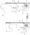
- Figure 1a-b show a preferred embodiment of the stick holder according to the invention, comprising two cooperating clamping elements 1, 2, which are linearly displaceable relative to each other, and wherein one of the clamping elements 1 is configured to be able to be attached onto a walking stick by means of a fastening part 1a, which can be mounted in the length against a walking stick (not shown), for example by means of straps or belts (not shown).
- Biasing means are provided which are configured to exert a biasing force on the clamping elements 1, 2 in order to drive them towards each other, as represented by the arrows 3.
- the biasing means include a constant-force spring of resilient ribbon (strip) material 5 rolled-up (coiled-up) around a reel 4.
- the rolled-up portion is mounted in a first clamping element 1 by bearing mounting the axis 6 of the reel 4 rotatably in a housing 7 of the first clamping element 1.
- the pull-out free outer end 8 of the resilient ribbon material 5 of the constant-force spring is connected to, for example, a hook-shaped connecting portion 9, which is provided in the second clamping element 2 that is displaceable relative to the first clamping element 1.
- the user intents to clamp his walking stick onto (for example) a tabletop
- the user firstly the user has to ensure that the projecting portion 12 of the upper clamping element 2 is positioned against the top surface of the (not shown) table, after which the walking stick (of which the bottom side must not be in contact with the floor) is pushed down by the user, thereby causing the lower clamping element 1, which is fixedly connected to walking stick, to be pushed down.
- the projecting portion 12 of the clamping element 2 remains pressed down against the upper surface of the table top, while the walking stick, including the lower clamping element 1, is pushed down against the spring pressure (biasing force) of the constant-force spring 5 - thereby aided by the weight of the walking stick -.
- the user pushes the walking stick including the two clamping elements 1, 2 in such a way in the direction of the table top, that the clamping elements 1, 2 clampingly engage the lower and upper surface of the table top respectively under the influence of the biasing force 3.
- the user may also use a hook-shaped member 13, which can be used to suspend the walking stick onto something, but which may also be used to pull up the upper clamping element 2, for clampingly engaging the walking stick onto the (table) edge. Accordingly, both the projecting portion 12 and the hook-shaped member 13 may be used to "open" the clamping elements 1, 2, in other words, to move the clamping elements away from one other during clampingly engaging the walking stick onto a (table) top.
- the walking stick When the walking stick is clamped onto a tabletop or another plank, the walking stick is able to be simply pulled away (detached) from the table top, after which the clamping members 1, 2 return to their rest position under the influence of the downwardly directed tension force of the free end 8 of the constant-force spring 5, as shown in figure 1a .
- the biasing force 3 which is mutually exerted by the clamping elements 1, 2 onto each other when in the closed position ( Figure 1a ), is substantially identical to the biasing force in the opened position ( Figure 1b ); thereby in practise considerably improving the ease of use of the walking stick holder.
- the biasing element serving as a constant-force spring 5 may be aesthetically and structurally in a responsible manner be housed in one of the clamping elements, for example in the clamping element 1, as shown in Figures 1a-b .
Landscapes
- Rehabilitation Tools (AREA)
Claims (4)
- Stockhalter für einen Gehstock, umfassend zwei zusammenwirkende Klemmelemente (1, 2), welche in Bezug zueinander linear verschiebbar sind, und wobei das erste Klemmelement dazu ausgelegt ist, dass es mittels eines Befestigungsteils (1a) in der Länge fest an dem Gehstock angebracht werden kann,
wobei ferner Vorspannmittel vorgesehen sind, welche ausgelegt sind, eine Vorspannkraft auf die Klemmelemente aufzubringen, die diese zueinander treibt,
wobei die Vorspannmittel eine Konstantkraftfeder (5) aus einem aufgerollten, elastischen Bandmaterial umfassen, deren aufgerollter Abschnitt im ersten Klemmelement (1) gehalten wird, und wobei das linear ausfahrbare freie äußere Ende (8) der Feder mit dem zweiten Klemmelement (2) verbunden ist,
wobei das erste Klemmelement ein Gehäuse (7) zum zumindest teilweisen Aufnehmen des aufgerollten Abschnitts der Konstantkraftfeder umfasst,
wobei der aufgerollte Abschnitt im ersten Klemmelement (1) gehalten ist, das dazu ausgelegt ist, dass es fest an den Gehstock angebracht werden kann,
dadurch gekennzeichnet, dass
die Konstantkraftfeder ein elastisches Bandmaterial (5) ist, das um eine Spule (4) aufgerollt ist, wobei der aufgerollte Abschnitt des Bandmaterials (5) durch ein Lager, das die Achse (6) der Spule (4) drehbar im Gehäuse (7) des ersten Klemmelements (1) hält, in dem ersten Klemmelement (1) gehalten ist. - Stockhalter nach Anspruch 1, wobei beim Einrasten des Stockhalters an einem Objekt das zweite Klemmelement (2) sich bezüglich des ersten Klemmelements (1) und bezüglich des Stockhalters, der fest mit dem ersten Klemmelement verbunden ist, nach oben bewegt.
- Stockhalter nach Anspruch 2, wobei das zweite Klemmelement (2) das freie äußere Ende (8) des elastischen Bandmaterials (5) herauszieht, wenn es sich bezüglich des ersten Klemmelements (1) nach oben bewegt.
- Stockhalter nach Anspruch 1-3, wobei das zweite Klemmelement (2) mit einem vorstehenden Abschnitt (12) und/oder einem hakenförmigen Bauteil (13) zum Öffnen der Klemmelemente (1, 2) versehen ist.
Applications Claiming Priority (2)
| Application Number | Priority Date | Filing Date | Title |
|---|---|---|---|
| NL1041061 | 2014-11-24 | ||
| PCT/NL2015/050810 WO2016085331A1 (en) | 2014-11-24 | 2015-11-19 | Walking stick holder with constant-force spring |
Publications (2)
| Publication Number | Publication Date |
|---|---|
| EP3223644A1 EP3223644A1 (de) | 2017-10-04 |
| EP3223644B1 true EP3223644B1 (de) | 2021-03-24 |
Family
ID=55273501
Family Applications (1)
| Application Number | Title | Priority Date | Filing Date |
|---|---|---|---|
| EP15831004.5A Active EP3223644B1 (de) | 2014-11-24 | 2015-11-19 | Spazierstockhalter mit konstantkraftfeder |
Country Status (2)
| Country | Link |
|---|---|
| EP (1) | EP3223644B1 (de) |
| WO (1) | WO2016085331A1 (de) |
Family Cites Families (2)
| Publication number | Priority date | Publication date | Assignee | Title |
|---|---|---|---|---|
| DE3838724A1 (de) * | 1987-12-07 | 1989-06-22 | Schmid Hans Armin | Vorrichtung zum fuehren eines bombierten bandes |
| RU2232537C2 (ru) * | 2002-11-18 | 2004-07-20 | Филатов Сергей Иванович | Зонт филатова |
-
2015
- 2015-11-19 EP EP15831004.5A patent/EP3223644B1/de active Active
- 2015-11-19 WO PCT/NL2015/050810 patent/WO2016085331A1/en not_active Ceased
Non-Patent Citations (1)
| Title |
|---|
| None * |
Also Published As
| Publication number | Publication date |
|---|---|
| EP3223644A1 (de) | 2017-10-04 |
| WO2016085331A1 (en) | 2016-06-02 |
Similar Documents
| Publication | Publication Date | Title |
|---|---|---|
| US8590553B2 (en) | Detent actuators, foldable apparatus including detent actuators, and related methods | |
| US8528796B1 (en) | Sock donning appliance | |
| US2802479A (en) | Adjustable resilient walking cane | |
| WO2007053280A3 (en) | Stationary exercise bicycle | |
| WO2011146200A3 (en) | Adaptable mobility aid device for level and inclined walkways and for stairs | |
| WO2017023878A3 (en) | Auxiliary sock device | |
| WO2007143092A3 (en) | Furniture that converts into a massage device | |
| EP3223644B1 (de) | Spazierstockhalter mit konstantkraftfeder | |
| US9901224B2 (en) | Toilet seat lifter | |
| WO2014009742A3 (en) | Walking frame and foot therefor | |
| WO2013063323A3 (en) | Supporting devices to enhance user comfort in a seated position | |
| KR20160059617A (ko) | 봉 걸레 | |
| EP3010380B1 (de) | Vorrichtung zum an- und ausziehen von socken und verwendung | |
| WO2006047327A3 (en) | Shower curtain holder | |
| US20130061894A1 (en) | Ferrule for Ambulatory Aids | |
| RU195405U1 (ru) | Универсальная трость | |
| GB2452120A (en) | A variable length bathboard | |
| KR20160012479A (ko) | 안마의자 다리마사지 유닛 | |
| KR20160000516U (ko) | 도어 열림 고정장치 | |
| KR20120064165A (ko) | 길이조절이 가능한 지팡이 | |
| TW201016377A (en) | Folding tool stand | |
| WO2009072865A3 (en) | Extensible table with improved extension mechanism | |
| US20190021533A1 (en) | Shoe donner staff | |
| CN103750609A (zh) | 一种带凳子的拐杖 | |
| CN211382539U (zh) | 一种多功能腋下拐杖 |
Legal Events
| Date | Code | Title | Description |
|---|---|---|---|
| STAA | Information on the status of an ep patent application or granted ep patent |
Free format text: STATUS: THE INTERNATIONAL PUBLICATION HAS BEEN MADE |
|
| PUAI | Public reference made under article 153(3) epc to a published international application that has entered the european phase |
Free format text: ORIGINAL CODE: 0009012 |
|
| STAA | Information on the status of an ep patent application or granted ep patent |
Free format text: STATUS: REQUEST FOR EXAMINATION WAS MADE |
|
| 17P | Request for examination filed |
Effective date: 20170626 |
|
| AK | Designated contracting states |
Kind code of ref document: A1 Designated state(s): AL AT BE BG CH CY CZ DE DK EE ES FI FR GB GR HR HU IE IS IT LI LT LU LV MC MK MT NL NO PL PT RO RS SE SI SK SM TR |
|
| AX | Request for extension of the european patent |
Extension state: BA ME |
|
| DAV | Request for validation of the european patent (deleted) | ||
| DAX | Request for extension of the european patent (deleted) | ||
| STAA | Information on the status of an ep patent application or granted ep patent |
Free format text: STATUS: EXAMINATION IS IN PROGRESS |
|
| RAP1 | Party data changed (applicant data changed or rights of an application transferred) |
Owner name: KOEVOETS GROUP B.V. |
|
| RIN1 | Information on inventor provided before grant (corrected) |
Inventor name: KOEVOETS, KOEN BEREND |
|
| 17Q | First examination report despatched |
Effective date: 20181105 |
|
| GRAP | Despatch of communication of intention to grant a patent |
Free format text: ORIGINAL CODE: EPIDOSNIGR1 |
|
| STAA | Information on the status of an ep patent application or granted ep patent |
Free format text: STATUS: GRANT OF PATENT IS INTENDED |
|
| INTG | Intention to grant announced |
Effective date: 20201015 |
|
| GRAS | Grant fee paid |
Free format text: ORIGINAL CODE: EPIDOSNIGR3 |
|
| GRAA | (expected) grant |
Free format text: ORIGINAL CODE: 0009210 |
|
| STAA | Information on the status of an ep patent application or granted ep patent |
Free format text: STATUS: THE PATENT HAS BEEN GRANTED |
|
| AK | Designated contracting states |
Kind code of ref document: B1 Designated state(s): AL AT BE BG CH CY CZ DE DK EE ES FI FR GB GR HR HU IE IS IT LI LT LU LV MC MK MT NL NO PL PT RO RS SE SI SK SM TR |
|
| REG | Reference to a national code |
Ref country code: GB Ref legal event code: FG4D |
|
| REG | Reference to a national code |
Ref country code: CH Ref legal event code: EP |
|
| REG | Reference to a national code |
Ref country code: IE Ref legal event code: FG4D |
|
| REG | Reference to a national code |
Ref country code: DE Ref legal event code: R096 Ref document number: 602015067294 Country of ref document: DE Ref country code: AT Ref legal event code: REF Ref document number: 1373583 Country of ref document: AT Kind code of ref document: T Effective date: 20210415 |
|
| REG | Reference to a national code |
Ref country code: NL Ref legal event code: FP |
|
| REG | Reference to a national code |
Ref country code: LT Ref legal event code: MG9D |
|
| PG25 | Lapsed in a contracting state [announced via postgrant information from national office to epo] |
Ref country code: NO Free format text: LAPSE BECAUSE OF FAILURE TO SUBMIT A TRANSLATION OF THE DESCRIPTION OR TO PAY THE FEE WITHIN THE PRESCRIBED TIME-LIMIT Effective date: 20210624 Ref country code: HR Free format text: LAPSE BECAUSE OF FAILURE TO SUBMIT A TRANSLATION OF THE DESCRIPTION OR TO PAY THE FEE WITHIN THE PRESCRIBED TIME-LIMIT Effective date: 20210324 Ref country code: FI Free format text: LAPSE BECAUSE OF FAILURE TO SUBMIT A TRANSLATION OF THE DESCRIPTION OR TO PAY THE FEE WITHIN THE PRESCRIBED TIME-LIMIT Effective date: 20210324 Ref country code: GR Free format text: LAPSE BECAUSE OF FAILURE TO SUBMIT A TRANSLATION OF THE DESCRIPTION OR TO PAY THE FEE WITHIN THE PRESCRIBED TIME-LIMIT Effective date: 20210625 Ref country code: BG Free format text: LAPSE BECAUSE OF FAILURE TO SUBMIT A TRANSLATION OF THE DESCRIPTION OR TO PAY THE FEE WITHIN THE PRESCRIBED TIME-LIMIT Effective date: 20210624 |
|
| PG25 | Lapsed in a contracting state [announced via postgrant information from national office to epo] |
Ref country code: RS Free format text: LAPSE BECAUSE OF FAILURE TO SUBMIT A TRANSLATION OF THE DESCRIPTION OR TO PAY THE FEE WITHIN THE PRESCRIBED TIME-LIMIT Effective date: 20210324 Ref country code: LV Free format text: LAPSE BECAUSE OF FAILURE TO SUBMIT A TRANSLATION OF THE DESCRIPTION OR TO PAY THE FEE WITHIN THE PRESCRIBED TIME-LIMIT Effective date: 20210324 Ref country code: SE Free format text: LAPSE BECAUSE OF FAILURE TO SUBMIT A TRANSLATION OF THE DESCRIPTION OR TO PAY THE FEE WITHIN THE PRESCRIBED TIME-LIMIT Effective date: 20210324 |
|
| REG | Reference to a national code |
Ref country code: AT Ref legal event code: MK05 Ref document number: 1373583 Country of ref document: AT Kind code of ref document: T Effective date: 20210324 |
|
| PG25 | Lapsed in a contracting state [announced via postgrant information from national office to epo] |
Ref country code: SM Free format text: LAPSE BECAUSE OF FAILURE TO SUBMIT A TRANSLATION OF THE DESCRIPTION OR TO PAY THE FEE WITHIN THE PRESCRIBED TIME-LIMIT Effective date: 20210324 Ref country code: AT Free format text: LAPSE BECAUSE OF FAILURE TO SUBMIT A TRANSLATION OF THE DESCRIPTION OR TO PAY THE FEE WITHIN THE PRESCRIBED TIME-LIMIT Effective date: 20210324 Ref country code: CZ Free format text: LAPSE BECAUSE OF FAILURE TO SUBMIT A TRANSLATION OF THE DESCRIPTION OR TO PAY THE FEE WITHIN THE PRESCRIBED TIME-LIMIT Effective date: 20210324 Ref country code: EE Free format text: LAPSE BECAUSE OF FAILURE TO SUBMIT A TRANSLATION OF THE DESCRIPTION OR TO PAY THE FEE WITHIN THE PRESCRIBED TIME-LIMIT Effective date: 20210324 Ref country code: LT Free format text: LAPSE BECAUSE OF FAILURE TO SUBMIT A TRANSLATION OF THE DESCRIPTION OR TO PAY THE FEE WITHIN THE PRESCRIBED TIME-LIMIT Effective date: 20210324 |
|
| PG25 | Lapsed in a contracting state [announced via postgrant information from national office to epo] |
Ref country code: SK Free format text: LAPSE BECAUSE OF FAILURE TO SUBMIT A TRANSLATION OF THE DESCRIPTION OR TO PAY THE FEE WITHIN THE PRESCRIBED TIME-LIMIT Effective date: 20210324 Ref country code: RO Free format text: LAPSE BECAUSE OF FAILURE TO SUBMIT A TRANSLATION OF THE DESCRIPTION OR TO PAY THE FEE WITHIN THE PRESCRIBED TIME-LIMIT Effective date: 20210324 Ref country code: PT Free format text: LAPSE BECAUSE OF FAILURE TO SUBMIT A TRANSLATION OF THE DESCRIPTION OR TO PAY THE FEE WITHIN THE PRESCRIBED TIME-LIMIT Effective date: 20210726 Ref country code: PL Free format text: LAPSE BECAUSE OF FAILURE TO SUBMIT A TRANSLATION OF THE DESCRIPTION OR TO PAY THE FEE WITHIN THE PRESCRIBED TIME-LIMIT Effective date: 20210324 Ref country code: IS Free format text: LAPSE BECAUSE OF FAILURE TO SUBMIT A TRANSLATION OF THE DESCRIPTION OR TO PAY THE FEE WITHIN THE PRESCRIBED TIME-LIMIT Effective date: 20210724 |
|
| REG | Reference to a national code |
Ref country code: DE Ref legal event code: R097 Ref document number: 602015067294 Country of ref document: DE |
|
| PG25 | Lapsed in a contracting state [announced via postgrant information from national office to epo] |
Ref country code: DK Free format text: LAPSE BECAUSE OF FAILURE TO SUBMIT A TRANSLATION OF THE DESCRIPTION OR TO PAY THE FEE WITHIN THE PRESCRIBED TIME-LIMIT Effective date: 20210324 Ref country code: ES Free format text: LAPSE BECAUSE OF FAILURE TO SUBMIT A TRANSLATION OF THE DESCRIPTION OR TO PAY THE FEE WITHIN THE PRESCRIBED TIME-LIMIT Effective date: 20210324 Ref country code: AL Free format text: LAPSE BECAUSE OF FAILURE TO SUBMIT A TRANSLATION OF THE DESCRIPTION OR TO PAY THE FEE WITHIN THE PRESCRIBED TIME-LIMIT Effective date: 20210324 |
|
| PLBE | No opposition filed within time limit |
Free format text: ORIGINAL CODE: 0009261 |
|
| STAA | Information on the status of an ep patent application or granted ep patent |
Free format text: STATUS: NO OPPOSITION FILED WITHIN TIME LIMIT |
|
| PG25 | Lapsed in a contracting state [announced via postgrant information from national office to epo] |
Ref country code: SI Free format text: LAPSE BECAUSE OF FAILURE TO SUBMIT A TRANSLATION OF THE DESCRIPTION OR TO PAY THE FEE WITHIN THE PRESCRIBED TIME-LIMIT Effective date: 20210324 |
|
| 26N | No opposition filed |
Effective date: 20220104 |
|
| PG25 | Lapsed in a contracting state [announced via postgrant information from national office to epo] |
Ref country code: IS Free format text: LAPSE BECAUSE OF FAILURE TO SUBMIT A TRANSLATION OF THE DESCRIPTION OR TO PAY THE FEE WITHIN THE PRESCRIBED TIME-LIMIT Effective date: 20210724 |
|
| PG25 | Lapsed in a contracting state [announced via postgrant information from national office to epo] |
Ref country code: MC Free format text: LAPSE BECAUSE OF FAILURE TO SUBMIT A TRANSLATION OF THE DESCRIPTION OR TO PAY THE FEE WITHIN THE PRESCRIBED TIME-LIMIT Effective date: 20210324 |
|
| REG | Reference to a national code |
Ref country code: CH Ref legal event code: PL |
|
| GBPC | Gb: european patent ceased through non-payment of renewal fee |
Effective date: 20211119 |
|
| PG25 | Lapsed in a contracting state [announced via postgrant information from national office to epo] |
Ref country code: LU Free format text: LAPSE BECAUSE OF NON-PAYMENT OF DUE FEES Effective date: 20211119 Ref country code: BE Free format text: LAPSE BECAUSE OF NON-PAYMENT OF DUE FEES Effective date: 20211130 |
|
| REG | Reference to a national code |
Ref country code: BE Ref legal event code: MM Effective date: 20211130 |
|
| PG25 | Lapsed in a contracting state [announced via postgrant information from national office to epo] |
Ref country code: IE Free format text: LAPSE BECAUSE OF NON-PAYMENT OF DUE FEES Effective date: 20211119 Ref country code: GB Free format text: LAPSE BECAUSE OF NON-PAYMENT OF DUE FEES Effective date: 20211119 |
|
| PG25 | Lapsed in a contracting state [announced via postgrant information from national office to epo] |
Ref country code: IT Free format text: LAPSE BECAUSE OF FAILURE TO SUBMIT A TRANSLATION OF THE DESCRIPTION OR TO PAY THE FEE WITHIN THE PRESCRIBED TIME-LIMIT Effective date: 20210324 |
|
| PG25 | Lapsed in a contracting state [announced via postgrant information from national office to epo] |
Ref country code: HU Free format text: LAPSE BECAUSE OF FAILURE TO SUBMIT A TRANSLATION OF THE DESCRIPTION OR TO PAY THE FEE WITHIN THE PRESCRIBED TIME-LIMIT; INVALID AB INITIO Effective date: 20151119 |
|
| PG25 | Lapsed in a contracting state [announced via postgrant information from national office to epo] |
Ref country code: CY Free format text: LAPSE BECAUSE OF FAILURE TO SUBMIT A TRANSLATION OF THE DESCRIPTION OR TO PAY THE FEE WITHIN THE PRESCRIBED TIME-LIMIT Effective date: 20210324 |
|
| PG25 | Lapsed in a contracting state [announced via postgrant information from national office to epo] |
Ref country code: LI Free format text: LAPSE BECAUSE OF NON-PAYMENT OF DUE FEES Effective date: 20220701 Ref country code: CH Free format text: LAPSE BECAUSE OF NON-PAYMENT OF DUE FEES Effective date: 20220701 |
|
| PG25 | Lapsed in a contracting state [announced via postgrant information from national office to epo] |
Ref country code: MK Free format text: LAPSE BECAUSE OF FAILURE TO SUBMIT A TRANSLATION OF THE DESCRIPTION OR TO PAY THE FEE WITHIN THE PRESCRIBED TIME-LIMIT Effective date: 20210324 |
|
| PG25 | Lapsed in a contracting state [announced via postgrant information from national office to epo] |
Ref country code: TR Free format text: LAPSE BECAUSE OF FAILURE TO SUBMIT A TRANSLATION OF THE DESCRIPTION OR TO PAY THE FEE WITHIN THE PRESCRIBED TIME-LIMIT Effective date: 20210324 |
|
| PG25 | Lapsed in a contracting state [announced via postgrant information from national office to epo] |
Ref country code: MT Free format text: LAPSE BECAUSE OF FAILURE TO SUBMIT A TRANSLATION OF THE DESCRIPTION OR TO PAY THE FEE WITHIN THE PRESCRIBED TIME-LIMIT Effective date: 20210324 |
|
| PGFP | Annual fee paid to national office [announced via postgrant information from national office to epo] |
Ref country code: NL Payment date: 20251119 Year of fee payment: 11 |
|
| PGFP | Annual fee paid to national office [announced via postgrant information from national office to epo] |
Ref country code: DE Payment date: 20251119 Year of fee payment: 11 |
|
| PGFP | Annual fee paid to national office [announced via postgrant information from national office to epo] |
Ref country code: FR Payment date: 20251126 Year of fee payment: 11 |