EP3223295B1 - Switch device - Google Patents
Switch device Download PDFInfo
- Publication number
- EP3223295B1 EP3223295B1 EP15860233.4A EP15860233A EP3223295B1 EP 3223295 B1 EP3223295 B1 EP 3223295B1 EP 15860233 A EP15860233 A EP 15860233A EP 3223295 B1 EP3223295 B1 EP 3223295B1
- Authority
- EP
- European Patent Office
- Prior art keywords
- operation panel
- support rod
- contact plate
- base body
- switch device
- Prior art date
- Legal status (The legal status is an assumption and is not a legal conclusion. Google has not performed a legal analysis and makes no representation as to the accuracy of the status listed.)
- Active
Links
Images




Classifications
-
- G—PHYSICS
- G05—CONTROLLING; REGULATING
- G05G—CONTROL DEVICES OR SYSTEMS INSOFAR AS CHARACTERISED BY MECHANICAL FEATURES ONLY
- G05G5/00—Means for preventing, limiting or returning the movements of parts of a control mechanism, e.g. locking controlling member
- G05G5/05—Means for returning or tending to return controlling members to an inoperative or neutral position, e.g. by providing return springs or resilient end-stops
-
- H—ELECTRICITY
- H01—ELECTRIC ELEMENTS
- H01H—ELECTRIC SWITCHES; RELAYS; SELECTORS; EMERGENCY PROTECTIVE DEVICES
- H01H25/00—Switches with compound movement of handle or other operating part
- H01H25/04—Operating part movable angularly in more than one plane, e.g. joystick
-
- G—PHYSICS
- G05—CONTROLLING; REGULATING
- G05G—CONTROL DEVICES OR SYSTEMS INSOFAR AS CHARACTERISED BY MECHANICAL FEATURES ONLY
- G05G9/00—Manually-actuated control mechanisms provided with one single controlling member co-operating with two or more controlled members, e.g. selectively, simultaneously
- G05G9/02—Manually-actuated control mechanisms provided with one single controlling member co-operating with two or more controlled members, e.g. selectively, simultaneously the controlling member being movable in different independent ways, movement in each individual way actuating one controlled member only
-
- H—ELECTRICITY
- H01—ELECTRIC ELEMENTS
- H01H—ELECTRIC SWITCHES; RELAYS; SELECTORS; EMERGENCY PROTECTIVE DEVICES
- H01H25/00—Switches with compound movement of handle or other operating part
- H01H25/04—Operating part movable angularly in more than one plane, e.g. joystick
- H01H25/041—Operating part movable angularly in more than one plane, e.g. joystick having a generally flat operating member depressible at different locations to operate different controls
-
- G—PHYSICS
- G05—CONTROLLING; REGULATING
- G05G—CONTROL DEVICES OR SYSTEMS INSOFAR AS CHARACTERISED BY MECHANICAL FEATURES ONLY
- G05G1/00—Controlling members, e.g. knobs or handles; Assemblies or arrangements thereof; Indicating position of controlling members
- G05G1/02—Controlling members for hand actuation by linear movement, e.g. push buttons
-
- H—ELECTRICITY
- H01—ELECTRIC ELEMENTS
- H01H—ELECTRIC SWITCHES; RELAYS; SELECTORS; EMERGENCY PROTECTIVE DEVICES
- H01H25/00—Switches with compound movement of handle or other operating part
- H01H25/04—Operating part movable angularly in more than one plane, e.g. joystick
- H01H25/041—Operating part movable angularly in more than one plane, e.g. joystick having a generally flat operating member depressible at different locations to operate different controls
- H01H2025/046—Operating part movable angularly in more than one plane, e.g. joystick having a generally flat operating member depressible at different locations to operate different controls having a spherical bearing between operating member and housing or bezel
Definitions
- Embodiments of the present disclosure relate to a switch device, and particularly to a switch device for controlling multiple switch units.
- the current mechanical switch device usually uses one switch button to control one switch unit, and at most uses one switch button to control two switch units.
- multiple switch buttons are usually disposed parallelly in one switch device to operate different switch units. There is a gap among the multiple switch buttons which are arranged together, the width of each gap may be varied and the slanting angle of each switch button may also be inconsistent. This causes unpleasing appearance of the switch device.
- arrangement of the multiple switch buttons on a limited surface of the switch device will cause the surface area of each button smaller, which is harmful for the user's convenient and accurate operation on the buttons.
- US 2010/108485 A1 discloses a switch device in accordance with the preamble of claim 1.
- US 2001/002127 A1 discloses a gimbal mounted joy stick.
- US 2002/056621 A1 discloses a multidirectional input device wherein a push-button switch in the input device is pushed by a protrusion formed at one end of a support portion of an interlock member.
- US 2004/020751 A1 discloses a swing type multi-way switch wherein a pair of side walls of an operation knob has tongue-like projections that are formed intergrally therewith and hang down from the lower edges of the knob for contacting switch elements.
- An object of the present disclosure is to provide a switch device which is used to solve
- a first end of the support rod is fixed to a center of the operation panel, a second end of the support rod extends into a support slot at the center of the base body, and the support rod is rotatably supported in the support slot such that the support rod can swing along with the slant motion of the operation panel.
- a first shaft is pivotally supported on the base body, a through slot is provided on the first shaft in an axial direction of the first shaft, the support rod passes through the through slot and is pivotally supported on the first shaft via a second shaft on the support rod, and an axial direction of the first shaft is perpendicular to the axial direction of the second shaft.
- the reset mechanism includes a spring and a reset pad located in the support slot and has a contact plate on the second end of the support rod. Furthermore the spring forces the reset pad to abut against the contact plate, and the reset pad is movably guided in the support slot in a direction perpendicular to a plane of the operation panel in the balanced state.
- a periphery of the contact plate is circular, and on a side of the contact plate in contact with the reset pad a boss is provided on the circular periphery of the contact plate to contact the reset pad.
- the reset mechanism includes a leaf spring in the support slot and has a contact plate at the second end of the support rod; and the leaf spring abuts against the contact plate.
- the second end of the support rod has a ball head, which is positioned on the base body by a positioning seat to form a spherical hinge.
- a contact plate is arranged between the first end and second end of the support rod, the reset mechanism comprises a spring located in the support slot, and the spring is held between a positioning seat and the contact plate.
- a guide slot is provided on the base body, and the support rod is guided by the guide slot.
- At least two switch units are distributed asymmetrically relative to a center of the operation panel.
- the switch device of the various embodiments of the present disclosure provides a single switch panel that can pivot and reset in various directions such that multiple switch units can be controlled only through the single switch panel.
- the single switch panel of the switch device avoids existence of the potential gap and unevenness among the multiple switch panels. Therefore, the switch device of the present disclosure has a more pleasing appearance.
- the single switch panel can have a relatively larger operating surface, the user can position and operate the switching panel more easily. This makes the operation of the switch device of the disclosure more convenient.
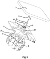
- Fig. 1 is an exploded view of the switch device according to one embodiment of the present disclosure.
- the switch device includes a base body 1, and a support slot 11 perpendicular to an end face of the base body 1 is disposed at a center of the base body 1. Multiple through holes 12 are distributed around the support slot 11, at least one switch unit 2 (four switch units are shown in Fig. 1 ) may be mounted to the base body 1, and an operable portion 21 of the switch unit 2 extends out of the base body 1 through the through hole 12.
- Each switch unit 2 is a known push button switch unit, and its operable portion 21 is a button. The characteristic of this type of push button switch unit is that when the button is pressed for the first time, the switch unit is closed; when the button is pressed again, the switch unit is opened.
- Each switch unit 2 may be connected to a separate circuit to control the on-off of the circuit.
- the switch device further includes an operation panel 3.
- the operation panel 3 is made of a hard material, for instance, the hard plastic.
- the operation panel 3 is movably connected to the base body 1 through the support rod 4.
- the support rod 4 is also made of a hard material, preferably being made of metal.
- a first end of the support rod 4 is fixed to the center of the operation panel 3, and its second end extends into the support slot 11 at the center of the base body 1.
- a side wall 112 of the support slot 11 of the base body 1 is provided with a support hole 13 (see Fig. 2 ).
- a shaft end 60 of two ends of a first shaft 6 extends into the support hole 13, and a shaft shoulder 62 thereon abuts against the side wall 112, such that the first shaft 6 is rotatably positioned on the base body 1 and goes across the support slot 11 in an axial direction of the first shaft.
- the first shaft 6 is provided with a through slot 61 in the axial direction of the first shaft 6.
- the support rod 4 passes through the through slot 61 and is pivotally supported in a shaft hole 63 on the first shaft 6 via a second shaft 41 (see Fig. 4 ) on the support rod 4, and the axial direction of the first shaft 6 is arranged perpendicular to the axial direction of the second shaft 41.
- the support rod 4 may swing in the axial direction of the first shaft 6 in the through slot 61 on the first shaft 6.
- the support rod 4 since the first shaft 6 is also pivotally supported on the base body 1, the support rod 4 may also rotate with the first shaft 6 relative to the base body 1.
- a portion 43 of the support rod 4 located in the through slot 61 has a larger width to facilitate arrangement of the second shaft 41 and facilitate guidance of the support rod 4 in the through slot 61 in the swing direction to avoid torsion.
- the support rod 4 supported by the two shafts may therefore achieve rotation in any direction by collaboration of the rotation motion of the two shafts.
- the support rod 4 can swing with the operation panel 3 without limiting the slant of the operation panel 3.
- the operation panel 3 is also supported on the base body 1 through the support rod 4 and the two shafts without being disengaged therefrom.
- each switch unit 2 is no longer limited to be distributed only at a position that is reachable by the turning of the operation panel 3 around one shaft, but can be distributed in any orientation around the center of the operation panel 3 as needed.
- at least two of the switch units 2 may not be centrosymmetrically distributed relative to the center of the operation panel 3.
- the switch device may include one to eight switch units 2.
- the multiple switch units 2 may advantageously be distributed evenly around the center of the operation panel 3 to maximize the included angle among between the respective adjacent switch units, thereby avoiding misoperation when of possibly pressing the multiple switch units 2 at the same time might be pressed at the same time by when the operation panel 3 when the operation panel 3 slants in one direction.
- the switch device further includes a reset mechanism 5 to drive the operation panel 3 to restore from any slant state relative to the base body 1 to a balanced state.
- the balanced state means a state in which the operation panel 3 does not press any of the multiple switch units 2.
- the reset mechanism 5 includes a spring 51 and a reset pad 52 located in the support slot 11.
- One end of the spring 51 abuts against the bottom wall 111 of the support slot 11, and the other end abuts against a side of the reset pad 52.
- a contact plate 42 is provided on the second end of the support rod 4.
- the spring 51 is preloaded to force the other side of the reset pad 52 abutting against the contact plate 42.
- An end face of the reset pad 52 has the shape and size substantially the same as the end face of the support slot 11 such that the reset pad 52 is movably guided in a direction perpendicular to the plane of the operation panel 3 in the balanced state (i.e., the axial of the support slot 11).
- a groove may be provided on the periphery of a side of the reset pad 52 in contact with the spring 51 so as to be fixed with the spring 51 (especially a spiral spring).
- On one side of the reset pad 52 in contact with the contact plate 42 may be formed an inwardly recessed receiving cavity to receive the contact plate 42.
- the periphery of the contact plate 42 is circular and the circular periphery of the contact plate 42 on the side in contact with the reset pad 52 may have an annular boss 421. As such, regardless of the direction in which the support rod 4 is slanted with the operation panel 3, the annular boss 421 on the contact plate 42 is in contact with the reset pad 52 on only one point on the edge thereof. This will help to correctly reset the operation panel by the reset pad 52, as will be described later in more detail.
- the spring 51 loads the contact panel 42 through the reset pad 52 in the axial direction of the support slot 11 and perpendicular to the end face of the base body 1. Since the force-receiving direction of the contact plate 42 is perpendicular to the end face of the base body 1, the support rod 4 will be maintained in the axial direction of the support slot 11 and in a direction perpendicular to the end face of the base body 1. As a result, the operation panel 3 fixed with the first end of the support rod 4 is thus maintained at a position parallel to the end face of the base body 1.
- the distances between the side and the buttons 21 of the respective switch units 2 are the same, such that the operation panel 3 does not press the button 21 of any switch unit 2, that is, in a balanced state. It is feasible to arrange the position of each switch unit 2 in a way of enabling the top of each button 21 just contact the operation panel 3 or slightly pressed by the operation panel 3 without reaching the stroke of switching the switch unit 2 in the balanced state, or. As an alternative, it is also possible to achieve such contact or slightly pressed state by providing an additional pad between the operation panel 3 and the button 21. As such, the operation panel 3 may be supported by each button 21 around its center, thereby avoiding the shaking of the operation panel 3.
- the operation panel 3 slants towards the force applying direction, and drives the button 21 of the corresponding switch unit 2 at the position to be pressed, such that the switch unit 2 switches from the opened state to the closed state, or from the closed state to the opened state.
- the support rod 4 slants as the operation panel 3 slants, and drives the contact plate 42 to slant to press the reset pad 52 at a point in the slant direction on the periphery thereof.
- the reset pad 52 as guided by the support slot 11, presses the spring 51 downwardly along the support slot 11 to accumulate the restoring force.
- the restoring force of the spring 51 lifts the reset pad 52.
- the reset pad 52 applies a restoring force to the contact plate 42 at the point in contact with the contact plate 42, such that the contact plate 42, together with the support rod 4 and the operation panel 3, rotate in the opposite direction to the slant direction until the contact plate 42 rotates to a position parallel to the end face of the reset pad 52.
- the reset pad 52 evenly applies the restoring force to the contact plate 42 on the entire periphery of the contact plate 42, instead of only on a point. Since a resultant moment received by the contact plate 42 is zero, the contact plate 42 will no longer rotate and will be kept in a balanced position instead. As a result, the operation panel 3 returns to the aforesaid balanced position, to facilitate the next pressing operation.
- the force-applying point for applying the force F2 on the operation panel 3 upon pressing next time may be at a position not centrosymmetrical with the point for applying the force F1 at the previous time about the center of the operation panel 3, for example at a position after rotation about the center by 90 degree (as shown in Fig. 7 ), such that the operation panel 3 slants in any direction asymmetric with the previous slant direction to operate other switch units 2.
- the spring 51 of the reset mechanism 5 may also be any other element, such as a leaf spring, that can achieve the elastic restoring force.
- the spring 51 is a leaf spring
- the reset pad 52 may be omitted, and the leaf spring 51 is directly in contact with the contact plate 42. Since the leaf spring 51 has a larger surface area, it can be assured that it is always in contact with the contact plate 42 and always exerts a restoring force.
- Figs. 8-11 show a switch device according to another embodiment of the present disclosure. Unlike the foregoing embodiment, a spherical hinge is used in the present embodiment instead of two orthogonal shafts in the above-described embodiment, to realize pivoting support of the operation panel in any direction.
- the second end of the support rod 4 has a ball head 44.
- a hemispherical ball seat 113 is formed at the bottom of the support slot 11 of the base body 1.
- the ball head 44 is accommodated in the ball seat 113 (see Figs. 9 and 10 ).
- a positioning seat 7 passes through the support rod 4 and engages with the base body 1, and has a hemispherical ball head cover on one side facing the ball head 44.
- the ball head 44 is enclosed in a spherical cavity formed by the ball seat 113 and the ball head cover to form a spherical hinge.
- the positioning seat 7 may be secured to base body 1 by snap-fitting elastic legs 71 thereon with a snap-fitting slot 114 (see Figs.
- the support rod 4 may likewise slant in any direction along with the operation panel 3 without hindering the slant of the operation panel 3.
- the spherical hinge also connects the operation panel 3 to the base body 1 such that it would not disengage from the base body 1.
- the contact plate 42 is provided between a first end and a second end of the support rod 4, and it may be formed integrally with the support rod 4, or may be sleeved around the support rod 4 and positioned through a stopper 45 on the support rod 4.
- the reset mechanism 5 includes a spring 51 located in the support slot 11. The spring 51 is maintained between the positioning seat 7 and the contact plate 42, thereby applying a restoring force to the support rod 4 and the operation panel 3 through the contact plate 42.
- a spring slot 72 (see Fig. 11 ) may be provided to hold one end of the spring 51.
- a side of the spring 51 which is compressed more provides the restoring force to the contact plate 42 at a position in contact with the contact plate 42, to produce a moment to drive the contact plate 42 together with the support rod 4 and the operation panel 3 to rotate in a direction opposite to the slant direction, until the contact plate 42 is perpendicular to the vertical direction of the spring 51.
- the spring 51 does not provide a restoring force to the contact plate 42, or provides the contact plate 42 with a restoring force evenly distributed around the periphery of the support rod 4 to zero the resultant moment of the contact plate 42.
- the contact plate 42 will no longer rotate but be kept in a balanced position.
- the operation panel 3 returns to the balanced position as described previously, to facilitate the next pressing operation.
- a guide slot may also be provided on the base body 1.
- the support rod 4 is guided through the guide slot.
- the guide slot is arranged to extend only along connection lines of the positions of the buttons 21 of the installed multiple switch units 2 and the center of the panel, such that when the user presses the operation panel 3, since the support rod 4 can only slant along the path of the guide slot, the operation panel 3 is guided to only slant towards the button 21 of one of the multiple switch units 2 to press the button 21. This avoids the slant of the operation panel in an incorrect slant direction of not pressing any switch unit 2 or simultaneously pressing multiple switch units 2 due to the improper pressing position on the operation panel 3, and makes the operation of the switch device more accurate and reliable.
- the guide slot is formed as a straight-line slot, triple-linear and radial slot, cross slot, six or eight linear and radial slot through an orthographic projection position of the center of the operation panel 3.
- the guide slot may be formed on a cover covering the end of the support slot 11 of the base body 1.
- the switch device of the various embodiments of the present disclosure provides a single switch panel 3 that can pivot and reset in various directions, such that multiple switch units can be controlled only through the single switch panel 3.
- the single switch panel of the switch device avoids existence of the potential gap and unevenness among the multiple switch panels. Therefore, the switch device of the present disclosure has a more pleasing appearance.
- the single switch panel can have a relatively larger operating surface, the user can position and operate the switching panel more easily. This makes the operation of the switch device of the disclosure more convenient.
- the switch device of the present disclosure is adapted to be installed in the slots on planes such as walls and panels, for domestic, commercial or industrial places.
- the various switch units in the switch device can be used to respectively control the lighting circuit, power supply, electrical equipment, and so on.
Landscapes
- Physics & Mathematics (AREA)
- General Physics & Mathematics (AREA)
- Engineering & Computer Science (AREA)
- Automation & Control Theory (AREA)
- Switches With Compound Operations (AREA)
- Rotary Switch, Piano Key Switch, And Lever Switch (AREA)
- Push-Button Switches (AREA)
Description
- Embodiments of the present disclosure relate to a switch device, and particularly to a switch device for controlling multiple switch units.
- The current mechanical switch device usually uses one switch button to control one switch unit, and at most uses one switch button to control two switch units. To achieve control of multiple switch units in one switch device, multiple switch buttons are usually disposed parallelly in one switch device to operate different switch units. There is a gap among the multiple switch buttons which are arranged together, the width of each gap may be varied and the slanting angle of each switch button may also be inconsistent. This causes unpleasing appearance of the switch device. Moreover, arrangement of the multiple switch buttons on a limited surface of the switch device will cause the surface area of each button smaller, which is harmful for the user's convenient and accurate operation on the buttons.
-
US 2010/108485 A1 discloses a switch device in accordance with the preamble ofclaim 1.US 2001/002127 A1 discloses a gimbal mounted joy stick.US 2002/056621 A1 discloses a multidirectional input device wherein a push-button switch in the input device is pushed by a protrusion formed at one end of a support portion of an interlock member.US 2004/020751 A1 discloses a swing type multi-way switch wherein a pair of side walls of an operation knob has tongue-like projections that are formed intergrally therewith and hang down from the lower edges of the knob for contacting switch elements. - Therefore, it is desirable to provide a switch device that can control multiple switch units, and has a pleasing appearance and easy-to-operate characteristic.
- An object of the present disclosure is to provide a switch device which is used to solve
- This object is solved by the features of
claim 1. - According to another embodiment of the present disclosure, a first end of the support rod is fixed to a center of the operation panel, a second end of the support rod extends into a support slot at the center of the base body, and the support rod is rotatably supported in the support slot such that the support rod can swing along with the slant motion of the operation panel.
- According to another embodiment of the present disclosure, a first shaft is pivotally supported on the base body, a through slot is provided on the first shaft in an axial direction of the first shaft, the support rod passes through the through slot and is pivotally supported on the first shaft via a second shaft on the support rod, and an axial direction of the first shaft is perpendicular to the axial direction of the second shaft.
- According to another embodiment of the present disclosure, the reset mechanism includes a spring and a reset pad located in the support slot and has a contact plate on the second end of the support rod. Furthermore the spring forces the reset pad to abut against the contact plate, and the reset pad is movably guided in the support slot in a direction perpendicular to a plane of the operation panel in the balanced state.
- According to another embodiment of the disclosure, a periphery of the contact plate is circular, and on a side of the contact plate in contact with the reset pad a boss is provided on the circular periphery of the contact plate to contact the reset pad.
- According to another embodiment of the present disclosure, the reset mechanism includes a leaf spring in the support slot and has a contact plate at the second end of the support rod; and the leaf spring abuts against the contact plate.
- According to another embodiment of the present disclosure, the second end of the support rod has a ball head, which is positioned on the base body by a positioning seat to form a spherical hinge.
- According to another embodiment of the disclosure, a contact plate is arranged between the first end and second end of the support rod, the reset mechanism comprises a spring located in the support slot, and the spring is held between a positioning seat and the contact plate.
- According to another embodiment of the present disclosure, a guide slot is provided on the base body, and the support rod is guided by the guide slot.
- According to another embodiment of the present disclosure, at least two switch units are distributed asymmetrically relative to a center of the operation panel.
- The switch device of the various embodiments of the present disclosure provides a single switch panel that can pivot and reset in various directions such that multiple switch units can be controlled only through the single switch panel. The single switch panel of the switch device avoids existence of the potential gap and unevenness among the multiple switch panels. Therefore, the switch device of the present disclosure has a more pleasing appearance. Moreover, since the single switch panel can have a relatively larger operating surface, the user can position and operate the switching panel more easily. This makes the operation of the switch device of the disclosure more convenient.
- The above and other objects and characteristics of the present disclosure shall be made more apparent in conjunction with the following detailed description with reference to the accompanying figures. In the figures,
-
Fig. 1 is an exploded view of a switch device according to an embodiment of the present disclosure; -
Fig. 2 shows a base body of the switch device inFig. 1 ; -
Fig. 3 shows a first shaft of the switch device inFig. 1 ; -
Fig. 4 shows a support rod of the switch device inFig. 1 ; -
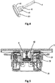
Fig. 5 shows a cross-sectional view of the switch device inFig. 1 , in which the operation panel is in a balanced position; -
Fig. 6 shows a cross-sectional view of the switch device inFig 1 , in which the operation panel is in an slanted state; -
Fig. 7 shows operable positions of the operation panel of the switch device inFig. 1 ; -
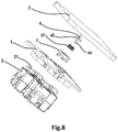
Fig. 8 is an exploded view of a switch device according to another embodiment of the present disclosure; -
Fig. 9 is a partially enlarged view of the cross section of the switch device inFig. 8 ; -
Fig. 10 shows the base body of the switch device inFig. 8 ; -
Fig. 11 shows a positioning seat of the switch device inFig. 8 . - Throughout the above figures, the same reference numbers are understood as designating the same, similar or corresponding characteristics or functions.
- Reference will be made to embodiments of the present disclosure, and one or more examples of embodiments are shown in the figures.
-
Fig. 1 is an exploded view of the switch device according to one embodiment of the present disclosure. The switch device includes abase body 1, and asupport slot 11 perpendicular to an end face of thebase body 1 is disposed at a center of thebase body 1. Multiple throughholes 12 are distributed around thesupport slot 11, at least one switch unit 2 (four switch units are shown inFig. 1 ) may be mounted to thebase body 1, and anoperable portion 21 of theswitch unit 2 extends out of thebase body 1 through thethrough hole 12. Eachswitch unit 2 is a known push button switch unit, and itsoperable portion 21 is a button. The characteristic of this type of push button switch unit is that when the button is pressed for the first time, the switch unit is closed; when the button is pressed again, the switch unit is opened. Eachswitch unit 2 may be connected to a separate circuit to control the on-off of the circuit. - The switch device further includes an
operation panel 3. Theoperation panel 3 is made of a hard material, for instance, the hard plastic. Theoperation panel 3 is movably connected to thebase body 1 through thesupport rod 4. Thesupport rod 4 is also made of a hard material, preferably being made of metal. - Specifically, a first end of the
support rod 4 is fixed to the center of theoperation panel 3, and its second end extends into thesupport slot 11 at the center of thebase body 1. Aside wall 112 of thesupport slot 11 of thebase body 1 is provided with a support hole 13 (seeFig. 2 ). With reference toFig. 3 , ashaft end 60 of two ends of afirst shaft 6 extends into thesupport hole 13, and ashaft shoulder 62 thereon abuts against theside wall 112, such that thefirst shaft 6 is rotatably positioned on thebase body 1 and goes across thesupport slot 11 in an axial direction of the first shaft. Thefirst shaft 6 is provided with athrough slot 61 in the axial direction of thefirst shaft 6. Thesupport rod 4 passes through the throughslot 61 and is pivotally supported in ashaft hole 63 on thefirst shaft 6 via a second shaft 41 (seeFig. 4 ) on thesupport rod 4, and the axial direction of thefirst shaft 6 is arranged perpendicular to the axial direction of thesecond shaft 41. Thus, thesupport rod 4 may swing in the axial direction of thefirst shaft 6 in the throughslot 61 on thefirst shaft 6. At the same time, since thefirst shaft 6 is also pivotally supported on thebase body 1, thesupport rod 4 may also rotate with thefirst shaft 6 relative to thebase body 1. Advantageously, aportion 43 of thesupport rod 4 located in the throughslot 61 has a larger width to facilitate arrangement of thesecond shaft 41 and facilitate guidance of thesupport rod 4 in the throughslot 61 in the swing direction to avoid torsion. - Since the
first shaft 6 and thesecond shaft 41 are perpendicular to each other, thesupport rod 4 supported by the two shafts may therefore achieve rotation in any direction by collaboration of the rotation motion of the two shafts. Thus, when theoperation panel 3 is pressed and slanted in any direction, thesupport rod 4 can swing with theoperation panel 3 without limiting the slant of theoperation panel 3. At the same time, theoperation panel 3 is also supported on thebase body 1 through thesupport rod 4 and the two shafts without being disengaged therefrom. - Since the
operation panel 3 may be pressed in any direction to be slanted, theoperation panel 3 may use its surface facing thebase body 1 to contact and press the respective switch units located in different orientations relative to the center of theoperation panel 3. Therefore, eachswitch unit 2 is no longer limited to be distributed only at a position that is reachable by the turning of theoperation panel 3 around one shaft, but can be distributed in any orientation around the center of theoperation panel 3 as needed. Particularly, at least two of theswitch units 2 may not be centrosymmetrically distributed relative to the center of theoperation panel 3. As a result, on the premise of space permission and convenient operation convenience, it is possible to install any number ofswitch units 2 around thesupport slot 11 in thebase body 1, and theoperation panel 3 may be pressed and slant towards each of theswitch units 2 and drive theswitch unit 2. Advantageously, the switch device may include one to eightswitch units 2. Moreover, themultiple switch units 2 may advantageously be distributed evenly around the center of theoperation panel 3 to maximize the included angle among between the respective adjacent switch units, thereby avoiding misoperation when of possibly pressing themultiple switch units 2 at the same time might be pressed at the same time by when theoperation panel 3 when theoperation panel 3 slants in one direction. - The switch device further includes a
reset mechanism 5 to drive theoperation panel 3 to restore from any slant state relative to thebase body 1 to a balanced state. The balanced state means a state in which theoperation panel 3 does not press any of themultiple switch units 2. - In the embodiment shown in
Figs. 1-6 , thereset mechanism 5 includes aspring 51 and areset pad 52 located in thesupport slot 11. One end of thespring 51 abuts against thebottom wall 111 of thesupport slot 11, and the other end abuts against a side of thereset pad 52. Acontact plate 42 is provided on the second end of thesupport rod 4. Thespring 51 is preloaded to force the other side of thereset pad 52 abutting against thecontact plate 42. An end face of thereset pad 52 has the shape and size substantially the same as the end face of thesupport slot 11 such that thereset pad 52 is movably guided in a direction perpendicular to the plane of theoperation panel 3 in the balanced state (i.e., the axial of the support slot 11). Advantageously, a groove may be provided on the periphery of a side of thereset pad 52 in contact with thespring 51 so as to be fixed with the spring 51 (especially a spiral spring). On one side of thereset pad 52 in contact with thecontact plate 42 may be formed an inwardly recessed receiving cavity to receive thecontact plate 42. Advantageously, the periphery of thecontact plate 42 is circular and the circular periphery of thecontact plate 42 on the side in contact with thereset pad 52 may have anannular boss 421. As such, regardless of the direction in which thesupport rod 4 is slanted with theoperation panel 3, theannular boss 421 on thecontact plate 42 is in contact with thereset pad 52 on only one point on the edge thereof. This will help to correctly reset the operation panel by thereset pad 52, as will be described later in more detail. - As shown in
Fig. 5 , when the user does not press theoperation panel 3, thespring 51 loads thecontact panel 42 through thereset pad 52 in the axial direction of thesupport slot 11 and perpendicular to the end face of thebase body 1. Since the force-receiving direction of thecontact plate 42 is perpendicular to the end face of thebase body 1, thesupport rod 4 will be maintained in the axial direction of thesupport slot 11 and in a direction perpendicular to the end face of thebase body 1. As a result, theoperation panel 3 fixed with the first end of thesupport rod 4 is thus maintained at a position parallel to the end face of thebase body 1. At this time, since one side of theoperation panel 3 facing thebase body 1 is flat, the distances between the side and thebuttons 21 of therespective switch units 2 are the same, such that theoperation panel 3 does not press thebutton 21 of anyswitch unit 2, that is, in a balanced state. It is feasible to arrange the position of eachswitch unit 2 in a way of enabling the top of eachbutton 21 just contact theoperation panel 3 or slightly pressed by theoperation panel 3 without reaching the stroke of switching theswitch unit 2 in the balanced state, or. As an alternative, it is also possible to achieve such contact or slightly pressed state by providing an additional pad between theoperation panel 3 and thebutton 21. As such, theoperation panel 3 may be supported by eachbutton 21 around its center, thereby avoiding the shaking of theoperation panel 3. - As shown in
Fig. 6 , when the user applies a force F1 to theoperation panel 3 towards the direction of aswitch unit 2, theoperation panel 3 slants towards the force applying direction, and drives thebutton 21 of thecorresponding switch unit 2 at the position to be pressed, such that theswitch unit 2 switches from the opened state to the closed state, or from the closed state to the opened state. At this time, thesupport rod 4 slants as theoperation panel 3 slants, and drives thecontact plate 42 to slant to press thereset pad 52 at a point in the slant direction on the periphery thereof. Thereset pad 52, as guided by thesupport slot 11, presses thespring 51 downwardly along thesupport slot 11 to accumulate the restoring force. - When the user no longer presses the operation panel, the restoring force of the
spring 51 lifts thereset pad 52. Thereset pad 52 applies a restoring force to thecontact plate 42 at the point in contact with thecontact plate 42, such that thecontact plate 42, together with thesupport rod 4 and theoperation panel 3, rotate in the opposite direction to the slant direction until thecontact plate 42 rotates to a position parallel to the end face of thereset pad 52. At this time, thereset pad 52 evenly applies the restoring force to thecontact plate 42 on the entire periphery of thecontact plate 42, instead of only on a point. Since a resultant moment received by thecontact plate 42 is zero, thecontact plate 42 will no longer rotate and will be kept in a balanced position instead. As a result, theoperation panel 3 returns to the aforesaid balanced position, to facilitate the next pressing operation. - When the
operation panel 3 is pressed again, it is feasible to select to press thesame switch unit 2 as in the previous operation, or press anyswitch unit 2 different from the one in the previous operation. Since thefirst shaft 6 and thesecond shaft 41 rotate in combination, the force-applying point for applying the force F2 on theoperation panel 3 upon pressing next time may be at a position not centrosymmetrical with the point for applying the force F1 at the previous time about the center of theoperation panel 3, for example at a position after rotation about the center by 90 degree (as shown inFig. 7 ), such that theoperation panel 3 slants in any direction asymmetric with the previous slant direction to operateother switch units 2. - The
spring 51 of thereset mechanism 5 may also be any other element, such as a leaf spring, that can achieve the elastic restoring force. In the case that thespring 51 is a leaf spring, thereset pad 52 may be omitted, and theleaf spring 51 is directly in contact with thecontact plate 42. Since theleaf spring 51 has a larger surface area, it can be assured that it is always in contact with thecontact plate 42 and always exerts a restoring force. -
Figs. 8-11 show a switch device according to another embodiment of the present disclosure. Unlike the foregoing embodiment, a spherical hinge is used in the present embodiment instead of two orthogonal shafts in the above-described embodiment, to realize pivoting support of the operation panel in any direction. - In the present embodiment, the second end of the
support rod 4 has aball head 44. Ahemispherical ball seat 113 is formed at the bottom of thesupport slot 11 of thebase body 1. Theball head 44 is accommodated in the ball seat 113 (seeFigs. 9 and 10 ). Apositioning seat 7 passes through thesupport rod 4 and engages with thebase body 1, and has a hemispherical ball head cover on one side facing theball head 44. Theball head 44 is enclosed in a spherical cavity formed by theball seat 113 and the ball head cover to form a spherical hinge. Thepositioning seat 7 may be secured tobase body 1 by snap-fittingelastic legs 71 thereon with a snap-fitting slot 114 (seeFigs. 10 and11 ) on the side wall of thesupport slot 11 of thebase body 1. Through this spherical hinge, thesupport rod 4 may likewise slant in any direction along with theoperation panel 3 without hindering the slant of theoperation panel 3. At the same time, the spherical hinge also connects theoperation panel 3 to thebase body 1 such that it would not disengage from thebase body 1. - In the present embodiment, the
contact plate 42 is provided between a first end and a second end of thesupport rod 4, and it may be formed integrally with thesupport rod 4, or may be sleeved around thesupport rod 4 and positioned through astopper 45 on thesupport rod 4. Thereset mechanism 5 includes aspring 51 located in thesupport slot 11. Thespring 51 is maintained between the positioningseat 7 and thecontact plate 42, thereby applying a restoring force to thesupport rod 4 and theoperation panel 3 through thecontact plate 42. On thepositioning seat 7, a spring slot 72 (seeFig. 11 ) may be provided to hold one end of thespring 51. - Similar to the embodiment described in
Figs. 1-7 , when a position of theoperation panel 3 corresponding to acertain switch unit 2 is pressed, theoperation panel 3 slants towards theswitch unit 2 and press thebutton 21 of theswitch unit 2. At this time, thesupport rod 4 slants along with theoperation panel 3 to drive thecontact plate 42 to slant. The slantedcontact plate 42 compresses thespring 51 towards one side to accumulate the restoring force. When the user no longer presses theoperation panel 3, a side of thespring 51 which is compressed more provides the restoring force to thecontact plate 42 at a position in contact with thecontact plate 42, to produce a moment to drive thecontact plate 42 together with thesupport rod 4 and theoperation panel 3 to rotate in a direction opposite to the slant direction, until thecontact plate 42 is perpendicular to the vertical direction of thespring 51. At this time, thespring 51 does not provide a restoring force to thecontact plate 42, or provides thecontact plate 42 with a restoring force evenly distributed around the periphery of thesupport rod 4 to zero the resultant moment of thecontact plate 42. As a result, thecontact plate 42 will no longer rotate but be kept in a balanced position. Thus, theoperation panel 3 returns to the balanced position as described previously, to facilitate the next pressing operation. - As for various embodiments of the present disclosure, a guide slot (not shown) may also be provided on the
base body 1. Thesupport rod 4 is guided through the guide slot. The guide slot is arranged to extend only along connection lines of the positions of thebuttons 21 of the installedmultiple switch units 2 and the center of the panel, such that when the user presses theoperation panel 3, since thesupport rod 4 can only slant along the path of the guide slot, theoperation panel 3 is guided to only slant towards thebutton 21 of one of themultiple switch units 2 to press thebutton 21. This avoids the slant of the operation panel in an incorrect slant direction of not pressing anyswitch unit 2 or simultaneously pressingmultiple switch units 2 due to the improper pressing position on theoperation panel 3, and makes the operation of the switch device more accurate and reliable. As for one (or two), three, four, six or eight switch units distributed evenly around the center of the operation panel, the guide slot is formed as a straight-line slot, triple-linear and radial slot, cross slot, six or eight linear and radial slot through an orthographic projection position of the center of theoperation panel 3. Preferably, the guide slot may be formed on a cover covering the end of thesupport slot 11 of thebase body 1. - The switch device of the various embodiments of the present disclosure provides a
single switch panel 3 that can pivot and reset in various directions, such that multiple switch units can be controlled only through thesingle switch panel 3. The single switch panel of the switch device avoids existence of the potential gap and unevenness among the multiple switch panels. Therefore, the switch device of the present disclosure has a more pleasing appearance. Moreover, since the single switch panel can have a relatively larger operating surface, the user can position and operate the switching panel more easily. This makes the operation of the switch device of the disclosure more convenient. - It should be understood that the switch device of the present disclosure is adapted to be installed in the slots on planes such as walls and panels, for domestic, commercial or industrial places. The various switch units in the switch device can be used to respectively control the lighting circuit, power supply, electrical equipment, and so on.
Claims (10)
- A switch device, comprising:a base body (1) on which multiple switch units (2) are installed;an operation panel (3) pivotally connected with the base body (1) via a support rod (4) such that the operation panel (3) can be operated to slant in several different directions relative to the base body (1) to respectively press each of said multiple switch units (2); anda reset mechanism (5) configured to drive the operation panel (3) to restore from any slant state relative to the base body (1) to a balanced state, the operation panel (3) not pressing any one of the multiple switch units (2) in this balanced state;characterized in that a surface of the operation panel (3) which faces the base body (1) contacts a respective switch unit (2) when the operation panel (3) is slanted.
- The switch device according to claim 1, wherein a first end of the support rod (4) is fixed to a center of the operation panel (3), and a second end of the support rod (4) extends into a support slot (11) at the center of the base body (1), and
the support rod (4) is rotatably supported in the support slot (11) such that the support rod (4) can swing along with the slant motion of the operation panel (3). - The switch device according to claim 2, wherein a first shaft (6) is pivotally supported on the base body (1), a through slot (61) is provided on the first shaft (6) in an axial direction of the first shaft (6), the support rod (4) passes through the through slot (61) and is pivotally supported on the first shaft (6) via a second shaft (41) on the support rod (4), and an axial direction of the first shaft (6) is perpendicular to an axial direction of the second shaft (41).
- The switch device according to claim 3, wherein the reset mechanism (5) includes a spring (51) and a reset pad (52) located in the support slot (11) and has a contact plate (42) on the second end of the support rod (4); and
wherein the spring (51) forces the reset pad (52) to abut against the contact plate (42), and the reset pad (52) is movably guided in the support slot (11) in a direction perpendicular to a plane of the operation panel (3) in the balanced state. - The switch device according to claim 4, wherein a periphery of the contact plate (42) is circular, and on a side of the contact plate in contact with the reset pad (52) a boss (421) is provided on the circular periphery of the contact plate to contact the reset pad (52).
- The switch device according to claim 3, wherein the reset mechanism (5) includes a leaf spring (51) located in the support slot (11) and has a contact plate (42) at the second end of the support rod (4); and the leaf spring (51) abuts against the contact plate (42).
- The switch device according to claim 2, wherein the second end of the support rod (4) has a ball head (44) which is positioned on the base body (1) by a positioning seat (7) to form a spherical hinge.
- The switch device according to claim 7, wherein a contact plate (42) is arranged between the first end and second end of the support rod (4), the reset mechanism (5) comprises a spring (51) located in the support slot (11), and the spring (51) is held between the positioning seat (7) and the contact plate (42).
- The switch device according to any of claims 1-8, wherein a guide slot is provided on the base body (1), and the support rod (4) is guided by the guide slot.
- The switch device according to any of claims 1-9, wherein at least two switch units (2) are distributed asymmetrically relative to a center of the operation panel (3).
Applications Claiming Priority (2)
| Application Number | Priority Date | Filing Date | Title |
|---|---|---|---|
| CN201410670628.2A CN105679589B (en) | 2014-11-20 | 2014-11-20 | Switching device |
| PCT/CN2015/093711 WO2016078510A1 (en) | 2014-11-20 | 2015-11-03 | Switch device |
Publications (3)
| Publication Number | Publication Date |
|---|---|
| EP3223295A1 EP3223295A1 (en) | 2017-09-27 |
| EP3223295A4 EP3223295A4 (en) | 2018-07-04 |
| EP3223295B1 true EP3223295B1 (en) | 2020-01-08 |
Family
ID=56013269
Family Applications (1)
| Application Number | Title | Priority Date | Filing Date |
|---|---|---|---|
| EP15860233.4A Active EP3223295B1 (en) | 2014-11-20 | 2015-11-03 | Switch device |
Country Status (3)
| Country | Link |
|---|---|
| EP (1) | EP3223295B1 (en) |
| CN (1) | CN105679589B (en) |
| WO (1) | WO2016078510A1 (en) |
Families Citing this family (4)
| Publication number | Priority date | Publication date | Assignee | Title |
|---|---|---|---|---|
| CN106741866A (en) * | 2016-12-29 | 2017-05-31 | 吴利祥 | A kind of aircraft that can automatically adjust balance |
| CN210091004U (en) | 2019-02-18 | 2020-02-18 | 杭州安费诺飞凤通信部品有限公司 | Pressing mechanism |
| CN112234971A (en) * | 2020-10-16 | 2021-01-15 | 温州新印像电气有限公司 | Automatic assembling system of switch |
| CN115547730A (en) * | 2022-10-21 | 2022-12-30 | 广东帝达聚智能科技有限责任公司 | Full flat rocker switch |
Family Cites Families (13)
| Publication number | Priority date | Publication date | Assignee | Title |
|---|---|---|---|---|
| US4439648A (en) * | 1982-07-28 | 1984-03-27 | Coleco Industries, Inc. | Joystick-type controller |
| US4896003A (en) * | 1989-06-30 | 1990-01-23 | Hsieh Man Ching | Multi-position electrical switch |
| JPH1153995A (en) * | 1997-07-30 | 1999-02-26 | Alps Electric Co Ltd | Multidirectional input device |
| US6353430B2 (en) * | 1999-03-23 | 2002-03-05 | Cts Corporation | Gimbal mounted joy stick with z-axis switch |
| US6504115B2 (en) * | 2000-03-07 | 2003-01-07 | Alps Electric Co., Ltd. | Multidirectional input device |
| TW494350B (en) * | 2000-12-06 | 2002-07-11 | Primax Electronics Ltd | Index apparatus of center supporting point |
| TWM241742U (en) * | 2002-07-17 | 2004-08-21 | Lite On Technology Corp | PDA and button apparatus of PDA |
| JP2004063317A (en) * | 2002-07-30 | 2004-02-26 | Japan Aviation Electronics Industry Ltd | Swing type multi-directional switch |
| CN2686073Y (en) * | 2004-01-12 | 2005-03-16 | 金宝电子工业股份有限公司 | Improved structure for multi-way key |
| JP4511479B2 (en) * | 2006-02-21 | 2010-07-28 | ホシデン株式会社 | Combined operation switch |
| CN2874753Y (en) * | 2006-03-06 | 2007-02-28 | 深圳市航盛电子股份有限公司 | Combined press button switch device |
| KR101339942B1 (en) * | 2007-02-27 | 2013-12-10 | 엘지전자 주식회사 | Mobile Communication Terminal having Input Device |
| DE102007013678A1 (en) * | 2007-03-22 | 2008-09-25 | Preh Gmbh | Operating element for a motor vehicle |
-
2014
- 2014-11-20 CN CN201410670628.2A patent/CN105679589B/en active Active
-
2015
- 2015-11-03 EP EP15860233.4A patent/EP3223295B1/en active Active
- 2015-11-03 WO PCT/CN2015/093711 patent/WO2016078510A1/en not_active Ceased
Non-Patent Citations (1)
| Title |
|---|
| None * |
Also Published As
| Publication number | Publication date |
|---|---|
| EP3223295A4 (en) | 2018-07-04 |
| WO2016078510A1 (en) | 2016-05-26 |
| CN105679589A (en) | 2016-06-15 |
| EP3223295A1 (en) | 2017-09-27 |
| CN105679589B (en) | 2019-07-30 |
Similar Documents
| Publication | Publication Date | Title |
|---|---|---|
| CN101286426B (en) | multi-directional input device | |
| KR960008882A (en) | Rotary switch and multi-directional input device | |
| US20110254788A1 (en) | Movable touch module and electronic device using the same | |
| US7230197B2 (en) | Movable contact, moveable contact unit including the same, and switch including the same movable contact | |
| EP3223295A1 (en) | Switch device | |
| US7492353B2 (en) | Joystick switching device | |
| JP2017199615A (en) | switch | |
| JP2007087945A (en) | Laptops that use multi-directional buttons and multi-directional buttons | |
| US8586885B2 (en) | Force-feedback multidirectional input device | |
| CN108257799A (en) | Electronic switch | |
| JP6895522B2 (en) | Click feeling giving mechanism | |
| US7262373B2 (en) | Multifunctional switch | |
| US9431192B2 (en) | Actuator biased by a horizontal member | |
| EP3582243B1 (en) | Four-way switch including malfunction prevention structure | |
| KR20140147244A (en) | Key apparatus for electronic appliances | |
| JP2002108473A (en) | Joy stick | |
| TW202443339A (en) | Multi-directional output device | |
| TWM583116U (en) | Rotary push switch with touch screen | |
| AU2017279690B2 (en) | Transmission device for push-button switch, push-button switch and socket | |
| US9362069B1 (en) | Multi-command trigger switch | |
| JP3937670B2 (en) | Multi-directional operation switch | |
| EP0918344A2 (en) | Switch device and electronic devices using the switch device | |
| KR101752831B1 (en) | Rotary electric component | |
| EP3214632B1 (en) | Multidirectional input device | |
| CN222146019U (en) | Switch |
Legal Events
| Date | Code | Title | Description |
|---|---|---|---|
| STAA | Information on the status of an ep patent application or granted ep patent |
Free format text: STATUS: THE INTERNATIONAL PUBLICATION HAS BEEN MADE |
|
| PUAI | Public reference made under article 153(3) epc to a published international application that has entered the european phase |
Free format text: ORIGINAL CODE: 0009012 |
|
| STAA | Information on the status of an ep patent application or granted ep patent |
Free format text: STATUS: REQUEST FOR EXAMINATION WAS MADE |
|
| 17P | Request for examination filed |
Effective date: 20170620 |
|
| AK | Designated contracting states |
Kind code of ref document: A1 Designated state(s): AL AT BE BG CH CY CZ DE DK EE ES FI FR GB GR HR HU IE IS IT LI LT LU LV MC MK MT NL NO PL PT RO RS SE SI SK SM TR |
|
| AX | Request for extension of the european patent |
Extension state: BA ME |
|
| DAV | Request for validation of the european patent (deleted) | ||
| DAX | Request for extension of the european patent (deleted) | ||
| A4 | Supplementary search report drawn up and despatched |
Effective date: 20180606 |
|
| RIC1 | Information provided on ipc code assigned before grant |
Ipc: G05G 9/047 20060101ALN20180531BHEP Ipc: H01H 25/04 20060101AFI20180531BHEP |
|
| GRAP | Despatch of communication of intention to grant a patent |
Free format text: ORIGINAL CODE: EPIDOSNIGR1 |
|
| STAA | Information on the status of an ep patent application or granted ep patent |
Free format text: STATUS: GRANT OF PATENT IS INTENDED |
|
| RIC1 | Information provided on ipc code assigned before grant |
Ipc: H01H 25/04 20060101AFI20190424BHEP Ipc: G05G 9/047 20060101ALN20190424BHEP |
|
| INTG | Intention to grant announced |
Effective date: 20190523 |
|
| GRAS | Grant fee paid |
Free format text: ORIGINAL CODE: EPIDOSNIGR3 |
|
| GRAA | (expected) grant |
Free format text: ORIGINAL CODE: 0009210 |
|
| STAA | Information on the status of an ep patent application or granted ep patent |
Free format text: STATUS: THE PATENT HAS BEEN GRANTED |
|
| AK | Designated contracting states |
Kind code of ref document: B1 Designated state(s): AL AT BE BG CH CY CZ DE DK EE ES FI FR GB GR HR HU IE IS IT LI LT LU LV MC MK MT NL NO PL PT RO RS SE SI SK SM TR |
|
| REG | Reference to a national code |
Ref country code: GB Ref legal event code: FG4D |
|
| REG | Reference to a national code |
Ref country code: CH Ref legal event code: EP Ref country code: CH Ref legal event code: NV Representative=s name: DR. GRAF AND PARTNER AG INTELLECTUAL PROPERTY, CH |
|
| REG | Reference to a national code |
Ref country code: DE Ref legal event code: R096 Ref document number: 602015045379 Country of ref document: DE |
|
| REG | Reference to a national code |
Ref country code: IE Ref legal event code: FG4D |
|
| REG | Reference to a national code |
Ref country code: AT Ref legal event code: REF Ref document number: 1223719 Country of ref document: AT Kind code of ref document: T Effective date: 20200215 |
|
| REG | Reference to a national code |
Ref country code: NL Ref legal event code: MP Effective date: 20200108 |
|
| REG | Reference to a national code |
Ref country code: LT Ref legal event code: MG4D |
|
| PG25 | Lapsed in a contracting state [announced via postgrant information from national office to epo] |
Ref country code: PT Free format text: LAPSE BECAUSE OF FAILURE TO SUBMIT A TRANSLATION OF THE DESCRIPTION OR TO PAY THE FEE WITHIN THE PRESCRIBED TIME-LIMIT Effective date: 20200531 Ref country code: NO Free format text: LAPSE BECAUSE OF FAILURE TO SUBMIT A TRANSLATION OF THE DESCRIPTION OR TO PAY THE FEE WITHIN THE PRESCRIBED TIME-LIMIT Effective date: 20200408 Ref country code: FI Free format text: LAPSE BECAUSE OF FAILURE TO SUBMIT A TRANSLATION OF THE DESCRIPTION OR TO PAY THE FEE WITHIN THE PRESCRIBED TIME-LIMIT Effective date: 20200108 Ref country code: LT Free format text: LAPSE BECAUSE OF FAILURE TO SUBMIT A TRANSLATION OF THE DESCRIPTION OR TO PAY THE FEE WITHIN THE PRESCRIBED TIME-LIMIT Effective date: 20200108 Ref country code: RS Free format text: LAPSE BECAUSE OF FAILURE TO SUBMIT A TRANSLATION OF THE DESCRIPTION OR TO PAY THE FEE WITHIN THE PRESCRIBED TIME-LIMIT Effective date: 20200108 Ref country code: NL Free format text: LAPSE BECAUSE OF FAILURE TO SUBMIT A TRANSLATION OF THE DESCRIPTION OR TO PAY THE FEE WITHIN THE PRESCRIBED TIME-LIMIT Effective date: 20200108 |
|
| PG25 | Lapsed in a contracting state [announced via postgrant information from national office to epo] |
Ref country code: GR Free format text: LAPSE BECAUSE OF FAILURE TO SUBMIT A TRANSLATION OF THE DESCRIPTION OR TO PAY THE FEE WITHIN THE PRESCRIBED TIME-LIMIT Effective date: 20200409 Ref country code: SE Free format text: LAPSE BECAUSE OF FAILURE TO SUBMIT A TRANSLATION OF THE DESCRIPTION OR TO PAY THE FEE WITHIN THE PRESCRIBED TIME-LIMIT Effective date: 20200108 Ref country code: IS Free format text: LAPSE BECAUSE OF FAILURE TO SUBMIT A TRANSLATION OF THE DESCRIPTION OR TO PAY THE FEE WITHIN THE PRESCRIBED TIME-LIMIT Effective date: 20200508 Ref country code: LV Free format text: LAPSE BECAUSE OF FAILURE TO SUBMIT A TRANSLATION OF THE DESCRIPTION OR TO PAY THE FEE WITHIN THE PRESCRIBED TIME-LIMIT Effective date: 20200108 Ref country code: HR Free format text: LAPSE BECAUSE OF FAILURE TO SUBMIT A TRANSLATION OF THE DESCRIPTION OR TO PAY THE FEE WITHIN THE PRESCRIBED TIME-LIMIT Effective date: 20200108 Ref country code: BG Free format text: LAPSE BECAUSE OF FAILURE TO SUBMIT A TRANSLATION OF THE DESCRIPTION OR TO PAY THE FEE WITHIN THE PRESCRIBED TIME-LIMIT Effective date: 20200408 |
|
| REG | Reference to a national code |
Ref country code: DE Ref legal event code: R097 Ref document number: 602015045379 Country of ref document: DE |
|
| PG25 | Lapsed in a contracting state [announced via postgrant information from national office to epo] |
Ref country code: EE Free format text: LAPSE BECAUSE OF FAILURE TO SUBMIT A TRANSLATION OF THE DESCRIPTION OR TO PAY THE FEE WITHIN THE PRESCRIBED TIME-LIMIT Effective date: 20200108 Ref country code: ES Free format text: LAPSE BECAUSE OF FAILURE TO SUBMIT A TRANSLATION OF THE DESCRIPTION OR TO PAY THE FEE WITHIN THE PRESCRIBED TIME-LIMIT Effective date: 20200108 Ref country code: CZ Free format text: LAPSE BECAUSE OF FAILURE TO SUBMIT A TRANSLATION OF THE DESCRIPTION OR TO PAY THE FEE WITHIN THE PRESCRIBED TIME-LIMIT Effective date: 20200108 Ref country code: RO Free format text: LAPSE BECAUSE OF FAILURE TO SUBMIT A TRANSLATION OF THE DESCRIPTION OR TO PAY THE FEE WITHIN THE PRESCRIBED TIME-LIMIT Effective date: 20200108 Ref country code: SK Free format text: LAPSE BECAUSE OF FAILURE TO SUBMIT A TRANSLATION OF THE DESCRIPTION OR TO PAY THE FEE WITHIN THE PRESCRIBED TIME-LIMIT Effective date: 20200108 Ref country code: SM Free format text: LAPSE BECAUSE OF FAILURE TO SUBMIT A TRANSLATION OF THE DESCRIPTION OR TO PAY THE FEE WITHIN THE PRESCRIBED TIME-LIMIT Effective date: 20200108 Ref country code: DK Free format text: LAPSE BECAUSE OF FAILURE TO SUBMIT A TRANSLATION OF THE DESCRIPTION OR TO PAY THE FEE WITHIN THE PRESCRIBED TIME-LIMIT Effective date: 20200108 |
|
| PLBE | No opposition filed within time limit |
Free format text: ORIGINAL CODE: 0009261 |
|
| STAA | Information on the status of an ep patent application or granted ep patent |
Free format text: STATUS: NO OPPOSITION FILED WITHIN TIME LIMIT |
|
| REG | Reference to a national code |
Ref country code: AT Ref legal event code: MK05 Ref document number: 1223719 Country of ref document: AT Kind code of ref document: T Effective date: 20200108 |
|
| 26N | No opposition filed |
Effective date: 20201009 |
|
| PG25 | Lapsed in a contracting state [announced via postgrant information from national office to epo] |
Ref country code: IT Free format text: LAPSE BECAUSE OF FAILURE TO SUBMIT A TRANSLATION OF THE DESCRIPTION OR TO PAY THE FEE WITHIN THE PRESCRIBED TIME-LIMIT Effective date: 20200108 Ref country code: AT Free format text: LAPSE BECAUSE OF FAILURE TO SUBMIT A TRANSLATION OF THE DESCRIPTION OR TO PAY THE FEE WITHIN THE PRESCRIBED TIME-LIMIT Effective date: 20200108 |
|
| PG25 | Lapsed in a contracting state [announced via postgrant information from national office to epo] |
Ref country code: SI Free format text: LAPSE BECAUSE OF FAILURE TO SUBMIT A TRANSLATION OF THE DESCRIPTION OR TO PAY THE FEE WITHIN THE PRESCRIBED TIME-LIMIT Effective date: 20200108 Ref country code: PL Free format text: LAPSE BECAUSE OF FAILURE TO SUBMIT A TRANSLATION OF THE DESCRIPTION OR TO PAY THE FEE WITHIN THE PRESCRIBED TIME-LIMIT Effective date: 20200108 |
|
| REG | Reference to a national code |
Ref country code: DE Ref legal event code: R119 Ref document number: 602015045379 Country of ref document: DE |
|
| PG25 | Lapsed in a contracting state [announced via postgrant information from national office to epo] |
Ref country code: MC Free format text: LAPSE BECAUSE OF FAILURE TO SUBMIT A TRANSLATION OF THE DESCRIPTION OR TO PAY THE FEE WITHIN THE PRESCRIBED TIME-LIMIT Effective date: 20200108 |
|
| GBPC | Gb: european patent ceased through non-payment of renewal fee |
Effective date: 20201103 |
|
| PG25 | Lapsed in a contracting state [announced via postgrant information from national office to epo] |
Ref country code: LU Free format text: LAPSE BECAUSE OF NON-PAYMENT OF DUE FEES Effective date: 20201103 |
|
| REG | Reference to a national code |
Ref country code: BE Ref legal event code: MM Effective date: 20201130 |
|
| PG25 | Lapsed in a contracting state [announced via postgrant information from national office to epo] |
Ref country code: FR Free format text: LAPSE BECAUSE OF NON-PAYMENT OF DUE FEES Effective date: 20201130 Ref country code: IE Free format text: LAPSE BECAUSE OF NON-PAYMENT OF DUE FEES Effective date: 20201103 |
|
| PG25 | Lapsed in a contracting state [announced via postgrant information from national office to epo] |
Ref country code: DE Free format text: LAPSE BECAUSE OF NON-PAYMENT OF DUE FEES Effective date: 20210601 Ref country code: GB Free format text: LAPSE BECAUSE OF NON-PAYMENT OF DUE FEES Effective date: 20201103 |
|
| PG25 | Lapsed in a contracting state [announced via postgrant information from national office to epo] |
Ref country code: TR Free format text: LAPSE BECAUSE OF FAILURE TO SUBMIT A TRANSLATION OF THE DESCRIPTION OR TO PAY THE FEE WITHIN THE PRESCRIBED TIME-LIMIT Effective date: 20200108 Ref country code: MT Free format text: LAPSE BECAUSE OF FAILURE TO SUBMIT A TRANSLATION OF THE DESCRIPTION OR TO PAY THE FEE WITHIN THE PRESCRIBED TIME-LIMIT Effective date: 20200108 Ref country code: CY Free format text: LAPSE BECAUSE OF FAILURE TO SUBMIT A TRANSLATION OF THE DESCRIPTION OR TO PAY THE FEE WITHIN THE PRESCRIBED TIME-LIMIT Effective date: 20200108 |
|
| PG25 | Lapsed in a contracting state [announced via postgrant information from national office to epo] |
Ref country code: MK Free format text: LAPSE BECAUSE OF FAILURE TO SUBMIT A TRANSLATION OF THE DESCRIPTION OR TO PAY THE FEE WITHIN THE PRESCRIBED TIME-LIMIT Effective date: 20200108 Ref country code: AL Free format text: LAPSE BECAUSE OF FAILURE TO SUBMIT A TRANSLATION OF THE DESCRIPTION OR TO PAY THE FEE WITHIN THE PRESCRIBED TIME-LIMIT Effective date: 20200108 |
|
| PG25 | Lapsed in a contracting state [announced via postgrant information from national office to epo] |
Ref country code: BE Free format text: LAPSE BECAUSE OF NON-PAYMENT OF DUE FEES Effective date: 20201130 |
|
| PGFP | Annual fee paid to national office [announced via postgrant information from national office to epo] |
Ref country code: CH Payment date: 20231201 Year of fee payment: 9 |
|
| REG | Reference to a national code |
Ref country code: CH Ref legal event code: PL |
|
| REG | Reference to a national code |
Ref country code: CH Ref legal event code: PL |
|
| PG25 | Lapsed in a contracting state [announced via postgrant information from national office to epo] |
Ref country code: CH Free format text: LAPSE BECAUSE OF NON-PAYMENT OF DUE FEES Effective date: 20241130 |