EP3223294A1 - Button guide structure - Google Patents
Button guide structure Download PDFInfo
- Publication number
- EP3223294A1 EP3223294A1 EP15860142.7A EP15860142A EP3223294A1 EP 3223294 A1 EP3223294 A1 EP 3223294A1 EP 15860142 A EP15860142 A EP 15860142A EP 3223294 A1 EP3223294 A1 EP 3223294A1
- Authority
- EP
- European Patent Office
- Prior art keywords
- tubular portion
- push button
- button
- front panel
- rib
- Prior art date
- Legal status (The legal status is an assumption and is not a legal conclusion. Google has not performed a legal analysis and makes no representation as to the accuracy of the status listed.)
- Granted
Links
- 238000000576 coating method Methods 0.000 description 18
- 239000011248 coating agent Substances 0.000 description 17
- 230000000873 masking effect Effects 0.000 description 16
- 239000000463 material Substances 0.000 description 8
- 238000005507 spraying Methods 0.000 description 4
- 238000005299 abrasion Methods 0.000 description 1
- 238000005034 decoration Methods 0.000 description 1
- 230000000694 effects Effects 0.000 description 1
- 230000005611 electricity Effects 0.000 description 1
- 230000004048 modification Effects 0.000 description 1
- 238000012986 modification Methods 0.000 description 1
- 230000000717 retained effect Effects 0.000 description 1
Images





Classifications
-
- H—ELECTRICITY
- H01—ELECTRIC ELEMENTS
- H01H—ELECTRIC SWITCHES; RELAYS; SELECTORS; EMERGENCY PROTECTIVE DEVICES
- H01H13/00—Switches having rectilinearly-movable operating part or parts adapted for pushing or pulling in one direction only, e.g. push-button switch
- H01H13/02—Details
- H01H13/12—Movable parts; Contacts mounted thereon
- H01H13/14—Operating parts, e.g. push-button
-
- H—ELECTRICITY
- H01—ELECTRIC ELEMENTS
- H01H—ELECTRIC SWITCHES; RELAYS; SELECTORS; EMERGENCY PROTECTIVE DEVICES
- H01H13/00—Switches having rectilinearly-movable operating part or parts adapted for pushing or pulling in one direction only, e.g. push-button switch
- H01H13/50—Switches having rectilinearly-movable operating part or parts adapted for pushing or pulling in one direction only, e.g. push-button switch having a single operating member
- H01H13/52—Switches having rectilinearly-movable operating part or parts adapted for pushing or pulling in one direction only, e.g. push-button switch having a single operating member the contact returning to its original state immediately upon removal of operating force, e.g. bell-push switch
-
- H—ELECTRICITY
- H01—ELECTRIC ELEMENTS
- H01H—ELECTRIC SWITCHES; RELAYS; SELECTORS; EMERGENCY PROTECTIVE DEVICES
- H01H2221/00—Actuators
- H01H2221/024—Transmission element
- H01H2221/026—Guiding or lubricating nylon
-
- H—ELECTRICITY
- H01—ELECTRIC ELEMENTS
- H01H—ELECTRIC SWITCHES; RELAYS; SELECTORS; EMERGENCY PROTECTIVE DEVICES
- H01H2221/00—Actuators
- H01H2221/024—Transmission element
- H01H2221/03—Stoppers for on or off position
-
- H—ELECTRICITY
- H01—ELECTRIC ELEMENTS
- H01H—ELECTRIC SWITCHES; RELAYS; SELECTORS; EMERGENCY PROTECTIVE DEVICES
- H01H2221/00—Actuators
- H01H2221/058—Actuators to avoid tilting or skewing of contact area or actuator
-
- H—ELECTRICITY
- H01—ELECTRIC ELEMENTS
- H01H—ELECTRIC SWITCHES; RELAYS; SELECTORS; EMERGENCY PROTECTIVE DEVICES
- H01H2231/00—Applications
- H01H2231/026—Car
Definitions
- the present invention relates to a button guide structure of an in-vehicle apparatus or the like including a push button on a front panel whose front surface is coated.
- the above button guide structure is constituted by a guide groove portion provided on the main body side of the apparatus and a guide rib provided on the push button, and the guide rib engages with the guide groove portion in a slidable manner.
- Patent Literature 1 Japanese Patent Laid-Open No. 2013-137972
- Patent Literature 1 for example, in the case where the surface of a front panel is coated by spraying coating material while the guide groove portion is provided on the front panel side of the main body of the apparatus, if the coating material is sprayed to the guide groove portion through an opening of the front panel and adheres to the guide groove portion, the adhered coating material sometimes exerts influence on the operation feeling for the push button, when the push button is incorporated in the main body of the apparatus after the coating is completed. For preventing this, the masking of the guide groove portion is necessary, leading to the increase in the cost for preparing a masking jig and the man-hour for performing the masking. Furthermore, even when the masking is performed, the coating material sometimes flows around to the guide groove portion, from small gaps, and the coating quality is likely to vary.
- An object of the present invention is to provide a button guide structure that makes it possible to achieve the reduction in cost and man-hour and the improvement in quality.
- an aspect of the present invention is a button guide structure in which a push button is provided on a front panel through a guide unit in a slidable manner, the push button operating a switch, the front panel configuring a front surface of an electronic apparatus or the like, in which the front panel includes a tubular portion into which a part of the push button is inserted, the push button includes: a button main body portion that is inserted into the tubular portion; and an outer tubular portion that is provided so as to surround the button main body portion and that encloses the tubular portion when the button main body portion has been inserted into the tubular portion, and the guide unit is provided on an outer surface of the tubular portion and the outer tubular portion.
- the coating material does not adhere to the guide unit provided on the outer surface side of the tubular portion. Therefore, unlike the related art, the masking of the guide unit for the coating is unnecessary, and it is possible to reduce the cost for the masking jig and the man-hour for the masking. Further, the variation in coating quality, which is generated in the case where the masking is performed, is not generated. It is possible to achieve the reduction in cost and man-hour and the improvement in quality.
- the guide unit may include: a rib that is provided on the outer surface of the tubular portion so as to extend in a slide direction of the push button; and a rib engagement portion that is provided on the outer tubular portion so as to engage with the rib in a slippable manner. According to this configuration, it is possible to adopt a simple structure in which the rib and the rib engagement portion are engaged in a slippable manner, and to reduce the cost.
- the rib engagement portion may be a slit or a groove. According to this configuration, it is possible to easily form the slit or the groove, and to reduce the cost.
- the rib may restrict a slide position of the push button, together with the rib engagement portion. According to this configuration, it is possible to configure a positioning portion for the push button by the rib and rib engagement portion that guide the push button, to achieve the simplification of the shapes of the front panel and the push button and the decrease in parts count, compared to the case where a positioning portion is separately provided, and to reduce the cost.
- a retaining unit may restrict the slide position of the push button, the retaining unit preventing the push button from coming off from the tubular portion.
- the retaining unit of the push button can serve also as a slide position restriction member, and it is possible to decrease the number of parts and to reduce the cost.
- the front panel in the aspect of the present invention includes the tubular portion into which a part of the button is inserted
- the push button includes the button main body portion that is inserted into the tubular portion, and the outer tubular portion that is provided so as to surround the button main body portion and that encloses the tubular portion when the button main body portion has been inserted into the tubular portion, and the guide unit is provided on the outer surface of the tubular portion and the outer tubular portion. Accordingly, when the front panel is coated, the coating material does not adhere to the guide unit provided on the outer surface side of the tubular portion. Therefore, unlike the related art, the masking of the guide unit for the coating is unnecessary, and it is possible to reduce the cost for the masking jig and the man-hour for the masking. Further, the variation in coating quality, which is generated in the case where the masking is performed, is not generated. It is possible to achieve the reduction in cost and man-hour and the improvement in quality.
- FIG. 1 is a perspective view of the in-vehicle device 10 that employs a push-button guide structure in an embodiment of the present invention.
- the in-vehicle device 10 includes a plastic front panel 11 that configures a front surface thereof, and a circuit board 13 that is attached to a rear portion of the front panel 11.
- reference numeral 15 denotes a screw for attaching the circuit board 13 to the front panel 11.
- the in-vehicle device 10 is an in-vehicle electronic apparatus such as an audio device that plays a CD, a DVD or the like, and a navigation device that searches a route to a designated destination, or the like, and is mounted so as to be embedded in a storage space provided on an instrument panel or the like of a vehicle.
- a plurality of plastic push buttons 21, 22, 23 are provided as operation units.
- one push button 23 is inserted into an opening 11a provided at an upper portion of the front panel 11, from the rear side, and is retained so as not to come off from the opening 11a.
- a switch 25 provided on the circuit board 13 abuts on a rear end portion of the push button 23. Accordingly, when the push button 23 is pushed from the near side of the in-vehicle device 10 to the far side, a moving contact of the switch 25 comes in contact with a fixed contact, and the switch 25 is turned on. As a result, a predetermined circuit provided on the circuit board 13 becomes a closed state so that electricity flows, resulting in the execution of a predetermined function.
- FIG. 2 is a perspective view showing the front panel 11 and the push button 23 attached to the front panel 11, as viewed diagonally from the front side.
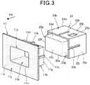
- FIG. 3 is a perspective view showing the front panel 11 and the push button 23 detached from the front panel 11, as viewed diagonally from the front side.
- the front panel 11 includes a front wall 11j having a nearly flat plate shape, the opening 11a opened on the front wall 11j, and a tubular portion 11b having a rectangular cross-section and extending rearward from an edge portion of the opening 11a nearly perpendicularly, and a part of the push button 23 is inserted into the tubular portion 11b from the rear side.
- spray coating is performed for coloration, decoration and the like.
- a plurality of dots in the figure show a coated surface obtained by the spray coating to the surface 11c.
- the coating material sprayed by the spray coating adheres not only to the surface 11c but also to an inner surface 11h of the tubular portion 11b, and forms a coated surface.
- the coating is not performed at least to a portion that slips on the tubular portion 11b and the like.
- the push button 23 includes a button main body portion 23a that is inserted into the tubular portion 11b, and a box-shaped outer tubular portion 23b that surrounds the button main body portion 23a.
- the button main body portion 23a includes a front wall 23c that is pushed by a finger or the like, and an upper wall 23d, a lower wall 23e and lateral walls 23f, 23g that extend from an upper edge, a lower edge and lateral edges of the front wall 23c, respectively.
- the outer tubular portion 23b is a portion that encloses the tubular portion 11b when the button main body portion 23a has been inserted into the tubular portion 11b, and includes an upper wall 23h, a lower wall 23j and lateral walls 23m, 23n that are provides so as to face the upper wall 23d, lower wall 23e and lateral walls 23f, 23g of the button main body portion 23a, respectively.
- On the upper wall 23h, the lower wall 23j and the lateral walls 23m, 23n, slits 23k that extend rearward from the respective front edge portions are formed.
- FIG. 4 is a perspective view showing the front panel 11 and the push button 23 attached to the front panel 11, as viewed diagonally from the rear side.
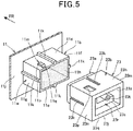
- FIG. 5 is a perspective view showing the front panel 11 and the push button 23 detached from the front panel 11, as viewed diagonally from the rear side.
- the tubular portion 11b of the front panel 11 is constituted by an upper wall 11d, a lower wall 11e and lateral walls 11f, 11g that integrally extend rearward from the front wall 11j, and ribs 11k that extend from the front wall 11j nearly perpendicularly, that is, extend in the front-rear direction are integrally formed on outer surfaces 11w of the upper wall 11d, the lower wall 11e and the lateral walls 11f, 11g.
- the ribs 11k and the slits 23k are engaged in a slippable manner, and the plurality of (four) ribs 11k and the plurality of (four) slits 23k constitute guide units 27.
- a stopper convex portion 11m that projects upward from the outer surface 11w is formed at one side of the rib 11k.
- the stopper convex portion 11m includes, on the upper surface, a flat surface 11p provided at a front side, and an inclined surface 11q formed at a rear portion in a rear downward direction.
- a stopper hole portion 23p that engages with the stopper convex portion 11m of the tubular portion 11b is formed at one side of the slit 23k.
- the stopper convex portion 11m and the stopper hole portion 23p constitute a retaining unit 28 that allows the push button 23 not to come off from the tubular portion 11b.
- the front ends of the stopper convex portion 11m and the stopper hole portion 23p abut on each other in the front-rear direction, and thereby, the push button 23 is avoided from coming off from the tubular portion 11b.
- the inclined surface 11q of the stopper convex portion 11m is a portion for easily moving the stopper convex portion 11m to the inside of the outer tubular portion 23b, which has flexibility, and smoothly engaging the stopper convex portion 11m and the stopper hole portion 23p when the push button 23 is attached to the tubular portion 11b.
- the button main body portion 23a and outer tubular portion 23b of the push button 23 are integrally connected by a frame-shaped connection wall 23q provided at the rear end.
- a thick portion 23r that has a sideways U-shape as viewed from the back side is integrally provided on an inner surface 23z of the button main body portion 23a, and a switch abutting portion 23t that projects rearward is integrally molded on a back surface 23s of the thick portion 23r.
- the switch abutting portion 23t is a portion that pushes the moving contact of the switch 25 (see FIG. 1 ), and when the push button 23 is pushed, the switch 25 is turned on by the switch abutting portion 23t.
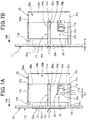
- FIGS. 6A and 6B are plan views showing the front panel 11 and the push button 23.
- FIG. 6A is a plan view showing the front wall 11j and tubular portion 11b of the front panel 11, and
- FIG. 6B is a plan view showing the push button 23.
- the ribs 11k on the upper wall 11d and lower wall 11e (see FIG. 5 ) of the front panel 11 are arranged at a central portion in the horizontal width (the width in the vertical direction in the figure) of the tubular portion 11b, and the ribs 11k on the lateral walls 11f, 11g are arranged at a central portion in the vertical width of the tubular portion 11b (see FIG. 5 ).
- the front end of the rib 11k is integrally connected with a back surface 11t of the front wall 11j, and a rear end surface 11u of the rib 11k is positioned on the same plane as a rear end surface 11v of the tubular portion 11b.
- the width W2 of the slit 23k is formed so as to be larger than the width W1 of the rib 11k, such that the rib 11k smoothly slides in the slit 23k.
- the wall thickness T of the outer tubular portion 23b (the wall thickness of the upper wall 23h, the lower wall 23j (see FIG. 5 ) and the lateral walls 23m, 23n) is formed so as to be smaller than the height H of the rib 11k from the outer surface 11w of the tubular portion 11b.
- a rear end surface 23w of the switch abutting portion 23t is positioned on the same plane as a back surface 23x of the connection wall 23q.
- the stopper convex portion 11m and the stopper hole portion 23p are formed such that the respective contours are rectangular shapes.
- FIGS. 7A and 7B are plan views showing fitted states of the tubular portion 11b of the front panel 11 and the push button 23.
- FIG. 7A is a plan view showing a state before the push button 23 is pushed
- FIG. 7B is a plan view a state after the push button 23 is pushed.
- a rear end surface 23u of the slit 23k of the push button 23 abuts on the rear end surface 11u of the rib 11k of the tubular portion 11b, and the positioning is performed such that the push button 23 is at the most forward position in the slide direction.
- the push button 23 is energized forward by the elastic force of the moving contact of the switch 25 (see FIG. 1 ), and as a result, the rear end surface 23u of the slit 23k is pressed on the rear end surface 11u of the rib 11k.
- a gap 31 with a clearance C1 is formed between a front end surface 11s of the stopper convex portion 11m of the tubular portion 11b and a front end surface 23v of the stopper hole portion 23p of the push button 23.
- FIG. 8 is a cross-sectional view taken from line VIII-VIII in FIG. 2 .
- An inner surface 24a of the outer tubular portion 23b of the push button 23 is fitted to the outer surface 11w of the tubular portion 11b of the front panel 11, in a slippable manner. Further, a gap 33 with a clearance C2 is provided between the inner surface 11h of the tubular portion 11b of the front panel 11 and an outer surface 23y of the button main body portion 23a of the push button 23. In the tubular portion 11b and the button main body portion 23a, the gap 33 is provided between the upper walls 11d, 23d (see FIG. 3 and FIG. 5 ), between the lower walls 11e, 23e (see FIG. 3 and FIG. 5 ), between the lateral walls 11f, 23f, and between the lateral walls 11g, 23g.
- the inner surface 24a of the outer tubular portion 23b is fitted to the outer surface 11w of the tubular portion 11b in a slippable manner and the gap 33 is provided between the inner surface 11h of the tubular portion 11b and the outer surface 23y of the button main body portion 23a in this way, it is possible to perform the slippage between the outer surface 11w of the tubular portion 11b and the inner surface 24a of the outer tubular portion 23b, which are not coated, to prevent the slippage between the coatings that are provided on the inner surface 11h of the tubular portion 11b and the outer surface 23y of the button main body portion 23a respectively, to enhance the operation feeling for the push button 23, and to avoid damages caused by the slippage.
- the rib 11k projects from the outer tubular portion 23b of the push button 23 by a projection amount P.
- the area of the slippage between the rib 11k and the slit 23k is maximized, and it is possible to suppress the abrasion caused by the slippage between the rib 11k and the slit 23k, for a long time, and to further increase the rigidity of the tubular portion 11b.
- the front panel 11 includes the tubular portion 11b into which a part of the push button 23 is inserted
- the push button 23 includes a button main body portion 23a that is inserted into the tubular portion 11b
- the outer tubular portion 23b that is provided so as to surround the button main body portion 23a and that encloses the tubular portion 11b when the button main body portion 23a has been inserted into the tubular portion 11b
- the guide unit 27 is provided on the outer surface 11w of the tubular portion 11b and the outer tubular portion 23b.
- the coating material does not adhere to the guide unit 27 provided on the outer surface 11w side of the tubular portion 11b. Therefore, unlike the related art, the masking of the guide unit for the coating is unnecessary, and it is possible to reduce the cost for the masking jig and the man-hour for the masking. Further, the variation in coating quality, which is generated in the case where the masking is performed, is not generated. It is possible to achieve the reduction in cost and man-hour and the improvement in quality.
- the guide unit 27 includes the rib 11k that is provided on the outer surface 11w of the tubular portion 11b so as to extend in the slide direction of the push button 23, and the slit 23k as the rib engagement unit that is provided on the outer tubular portion 23b so as to engage with the rib 11k in a slippable manner. Therefore, it is possible to adopt a simple structure in which the rib 11k and the slit 23k are engaged in a slippable manner, and to reduce the cost.
- the rib engagement portion is the slit 23k, it is possible to easily form the slit 23k, and to reduce the cost.
- the rib 11k restricts the slide position of the push button 23, together with the rib 11k. Therefore, it is possible to configure a positioning portion for the push button 23 by the rib 11k and slit 23k that guide the push button 23, to achieve the simplification of the shapes of the front panel 11 and the push button 23 and the decrease in parts count, compared to the case where a positioning portion is separately provided, and to reduce the cost.
- the retaining unit 28 for preventing the push button 23 from coming off from the tubular portion 11b restricts the slide position of the push button 23. Therefore, the retaining unit 28 of the push button 23 can serve also as a slide position restriction member, and it is possible to decrease the number of parts and to reduce the cost.
- the slit 23k is provided as the rib engagement portion that is provided on the outer tubular portion 23b so as to engage with the rib 11k in a slippable manner, but without being limited to this, as the rib engagement portion, a groove (concave portion) that engages with the rib of the tubular portion of the front panel in a slippable manner may be provided on the inner surface of the outer tubular portion of the push button.
- a concave-shaped portion that extends in the slide direction of the push button may be provided on the outer surface of the tubular portion of the front panel, and a convex-shaped portion that engages with the above concave-shaped portion in a slidable manner may be provided on the inner surface of the outer tubular portion of the push button.
Landscapes
- Push-Button Switches (AREA)
Abstract
Description
- The present invention relates to a button guide structure of an in-vehicle apparatus or the like including a push button on a front panel whose front surface is coated.
- Conventionally, there is known a button guide structure to guide a push button that is used in the operation of an in-vehicle apparatus or the like, in a slidable manner (for example, see Patent Literature 1).
- The above button guide structure is constituted by a guide groove portion provided on the main body side of the apparatus and a guide rib provided on the push button, and the guide rib engages with the guide groove portion in a slidable manner.
- Patent Literature 1: Japanese Patent Laid-Open No.
2013-137972 - In Patent Literature 1, for example, in the case where the surface of a front panel is coated by spraying coating material while the guide groove portion is provided on the front panel side of the main body of the apparatus, if the coating material is sprayed to the guide groove portion through an opening of the front panel and adheres to the guide groove portion, the adhered coating material sometimes exerts influence on the operation feeling for the push button, when the push button is incorporated in the main body of the apparatus after the coating is completed. For preventing this, the masking of the guide groove portion is necessary, leading to the increase in the cost for preparing a masking jig and the man-hour for performing the masking. Furthermore, even when the masking is performed, the coating material sometimes flows around to the guide groove portion, from small gaps, and the coating quality is likely to vary.
- An object of the present invention is to provide a button guide structure that makes it possible to achieve the reduction in cost and man-hour and the improvement in quality.
- The present description includes all contents of Japanese Patent Application No.
2014-236568 - For solving the above-described problem, an aspect of the present invention is a button guide structure in which a push button is provided on a front panel through a guide unit in a slidable manner, the push button operating a switch, the front panel configuring a front surface of an electronic apparatus or the like, in which the front panel includes a tubular portion into which a part of the push button is inserted, the push button includes: a button main body portion that is inserted into the tubular portion; and an outer tubular portion that is provided so as to surround the button main body portion and that encloses the tubular portion when the button main body portion has been inserted into the tubular portion, and the guide unit is provided on an outer surface of the tubular portion and the outer tubular portion.
- According to this configuration, when the front panel is coated, the coating material does not adhere to the guide unit provided on the outer surface side of the tubular portion. Therefore, unlike the related art, the masking of the guide unit for the coating is unnecessary, and it is possible to reduce the cost for the masking jig and the man-hour for the masking. Further, the variation in coating quality, which is generated in the case where the masking is performed, is not generated. It is possible to achieve the reduction in cost and man-hour and the improvement in quality.
- In the above configuration, the guide unit may include: a rib that is provided on the outer surface of the tubular portion so as to extend in a slide direction of the push button; and a rib engagement portion that is provided on the outer tubular portion so as to engage with the rib in a slippable manner. According to this configuration, it is possible to adopt a simple structure in which the rib and the rib engagement portion are engaged in a slippable manner, and to reduce the cost.
- Further, in the above configuration, the rib engagement portion may be a slit or a groove. According to this configuration, it is possible to easily form the slit or the groove, and to reduce the cost.
- Further, in the above configuration, the rib may restrict a slide position of the push button, together with the rib engagement portion. According to this configuration, it is possible to configure a positioning portion for the push button by the rib and rib engagement portion that guide the push button, to achieve the simplification of the shapes of the front panel and the push button and the decrease in parts count, compared to the case where a positioning portion is separately provided, and to reduce the cost.
- Further, in the above configuration, a retaining unit may restrict the slide position of the push button, the retaining unit preventing the push button from coming off from the tubular portion. According to this configuration, the retaining unit of the push button can serve also as a slide position restriction member, and it is possible to decrease the number of parts and to reduce the cost.
- The front panel in the aspect of the present invention includes the tubular portion into which a part of the button is inserted, the push button includes the button main body portion that is inserted into the tubular portion, and the outer tubular portion that is provided so as to surround the button main body portion and that encloses the tubular portion when the button main body portion has been inserted into the tubular portion, and the guide unit is provided on the outer surface of the tubular portion and the outer tubular portion. Accordingly, when the front panel is coated, the coating material does not adhere to the guide unit provided on the outer surface side of the tubular portion. Therefore, unlike the related art, the masking of the guide unit for the coating is unnecessary, and it is possible to reduce the cost for the masking jig and the man-hour for the masking. Further, the variation in coating quality, which is generated in the case where the masking is performed, is not generated. It is possible to achieve the reduction in cost and man-hour and the improvement in quality.
-
- [
FIG. 1] FIG. 1 is a perspective view of an in-vehicle device that employs a push-button guide structure in an embodiment of the present invention. - [
FIG. 2] FIG. 2 is a perspective view showing a front panel and a push button attached to the front panel, as viewed diagonally from the front side. - [
FIG. 3] FIG. 3 is a perspective view showing the front panel and the push button detached from the front panel, as viewed diagonally from the front side. - [
FIG. 4] FIG. 4 is a perspective view showing the front panel and the push button attached to the front panel, as viewed diagonally from the rear side. - [
FIG. 5] FIG. 5 is a perspective view showing the front panel and the push button detached from the front panel, as viewed diagonally from the rear side. - [
FIG. 6] FIGS. 6A and 6B are plan views showing the front panel and the push button, in whichFIG. 6A is a plan view showing a front wall and a tubular portion of the front panel andFIG. 6B is a plan view showing the push button. - [
FIG. 7] FIGS. 7A and 7B are plan views showing fitted states of the tubular portion of the front panel and the push button, in whichFIG. 7A is a plan view showing a state before the push button is pushed andFIG. 7B is a plan view showing a state after the push button is pushed. - [
FIG. 8] FIG. 8 is a cross-sectional view taken from line VIII-VIII inFIG. 2 . - Hereinafter, an embodiment of the present invention will be described with reference to the drawings. Here, in each drawing, the near side (front side) of an in-
vehicle device 10 is indicated by an arrow FR. -
FIG. 1 is a perspective view of the in-vehicle device 10 that employs a push-button guide structure in an embodiment of the present invention. - The in-
vehicle device 10 includes aplastic front panel 11 that configures a front surface thereof, and acircuit board 13 that is attached to a rear portion of thefront panel 11. Here,reference numeral 15 denotes a screw for attaching thecircuit board 13 to thefront panel 11. - The in-
vehicle device 10 is an in-vehicle electronic apparatus such as an audio device that plays a CD, a DVD or the like, and a navigation device that searches a route to a designated destination, or the like, and is mounted so as to be embedded in a storage space provided on an instrument panel or the like of a vehicle. - On the
front panel 11, a plurality ofplastic push buttons push button 23 is inserted into an opening 11a provided at an upper portion of thefront panel 11, from the rear side, and is retained so as not to come off from the opening 11a. Furthermore, aswitch 25 provided on thecircuit board 13 abuts on a rear end portion of thepush button 23. Accordingly, when thepush button 23 is pushed from the near side of the in-vehicle device 10 to the far side, a moving contact of theswitch 25 comes in contact with a fixed contact, and theswitch 25 is turned on. As a result, a predetermined circuit provided on thecircuit board 13 becomes a closed state so that electricity flows, resulting in the execution of a predetermined function. -
FIG. 2 is a perspective view showing thefront panel 11 and thepush button 23 attached to thefront panel 11, as viewed diagonally from the front side.FIG. 3 is a perspective view showing thefront panel 11 and thepush button 23 detached from thefront panel 11, as viewed diagonally from the front side. - As shown in
FIG. 2 andFIG. 3 , thefront panel 11 includes afront wall 11j having a nearly flat plate shape, the opening 11a opened on thefront wall 11j, and atubular portion 11b having a rectangular cross-section and extending rearward from an edge portion of the opening 11a nearly perpendicularly, and a part of thepush button 23 is inserted into thetubular portion 11b from the rear side. - To a
surface 11c on the front side of thefront wall 11j, spray coating is performed for coloration, decoration and the like. A plurality of dots in the figure show a coated surface obtained by the spray coating to thesurface 11c. The coating material sprayed by the spray coating adheres not only to thesurface 11c but also to aninner surface 11h of thetubular portion 11b, and forms a coated surface. Here, on thepush button 23, the coating is not performed at least to a portion that slips on thetubular portion 11b and the like. - The
push button 23 includes a buttonmain body portion 23a that is inserted into thetubular portion 11b, and a box-shaped outertubular portion 23b that surrounds the buttonmain body portion 23a. - The button
main body portion 23a includes afront wall 23c that is pushed by a finger or the like, and anupper wall 23d, alower wall 23e andlateral walls front wall 23c, respectively. - The outer
tubular portion 23b is a portion that encloses thetubular portion 11b when the buttonmain body portion 23a has been inserted into thetubular portion 11b, and includes anupper wall 23h, alower wall 23j andlateral walls upper wall 23d,lower wall 23e andlateral walls main body portion 23a, respectively. On theupper wall 23h, thelower wall 23j and thelateral walls -
FIG. 4 is a perspective view showing thefront panel 11 and thepush button 23 attached to thefront panel 11, as viewed diagonally from the rear side.FIG. 5 is a perspective view showing thefront panel 11 and thepush button 23 detached from thefront panel 11, as viewed diagonally from the rear side. - As shown in
FIG. 4 andFIG. 5 , thetubular portion 11b of thefront panel 11 is constituted by anupper wall 11d, alower wall 11e andlateral walls front wall 11j, andribs 11k that extend from thefront wall 11j nearly perpendicularly, that is, extend in the front-rear direction are integrally formed onouter surfaces 11w of theupper wall 11d, thelower wall 11e and thelateral walls ribs 11k and theslits 23k are engaged in a slippable manner, and the plurality of (four)ribs 11k and the plurality of (four)slits 23k constituteguide units 27. - On the
upper wall 11d, a stopperconvex portion 11m that projects upward from theouter surface 11w is formed at one side of therib 11k. The stopperconvex portion 11m includes, on the upper surface, aflat surface 11p provided at a front side, and aninclined surface 11q formed at a rear portion in a rear downward direction. - On the
upper wall 23h of thepush button 23, astopper hole portion 23p that engages with the stopperconvex portion 11m of thetubular portion 11b is formed at one side of theslit 23k. The stopperconvex portion 11m and thestopper hole portion 23p constitute a retainingunit 28 that allows thepush button 23 not to come off from thetubular portion 11b. The front ends of the stopperconvex portion 11m and thestopper hole portion 23p abut on each other in the front-rear direction, and thereby, thepush button 23 is avoided from coming off from thetubular portion 11b. Theinclined surface 11q of the stopperconvex portion 11m is a portion for easily moving the stopperconvex portion 11m to the inside of the outertubular portion 23b, which has flexibility, and smoothly engaging the stopperconvex portion 11m and thestopper hole portion 23p when thepush button 23 is attached to thetubular portion 11b. - The button
main body portion 23a and outertubular portion 23b of thepush button 23 are integrally connected by a frame-shapedconnection wall 23q provided at the rear end. - A
thick portion 23r that has a sideways U-shape as viewed from the back side is integrally provided on aninner surface 23z of the buttonmain body portion 23a, and aswitch abutting portion 23t that projects rearward is integrally molded on aback surface 23s of thethick portion 23r. Theswitch abutting portion 23t is a portion that pushes the moving contact of the switch 25 (seeFIG. 1 ), and when thepush button 23 is pushed, theswitch 25 is turned on by theswitch abutting portion 23t. -
FIGS. 6A and 6B are plan views showing thefront panel 11 and thepush button 23.FIG. 6A is a plan view showing thefront wall 11j andtubular portion 11b of thefront panel 11, andFIG. 6B is a plan view showing thepush button 23. - As shown in
FIGS. 6A and 6B , theribs 11k on theupper wall 11d andlower wall 11e (seeFIG. 5 ) of thefront panel 11 are arranged at a central portion in the horizontal width (the width in the vertical direction in the figure) of thetubular portion 11b, and theribs 11k on thelateral walls tubular portion 11b (seeFIG. 5 ). - The front end of the
rib 11k is integrally connected with aback surface 11t of thefront wall 11j, and arear end surface 11u of therib 11k is positioned on the same plane as arear end surface 11v of thetubular portion 11b. - Further, the width W2 of the
slit 23k is formed so as to be larger than the width W1 of therib 11k, such that therib 11k smoothly slides in theslit 23k. The wall thickness T of the outertubular portion 23b (the wall thickness of theupper wall 23h, thelower wall 23j (seeFIG. 5 ) and thelateral walls rib 11k from theouter surface 11w of thetubular portion 11b. - A
rear end surface 23w of theswitch abutting portion 23t is positioned on the same plane as aback surface 23x of theconnection wall 23q. The stopperconvex portion 11m and thestopper hole portion 23p are formed such that the respective contours are rectangular shapes. -
FIGS. 7A and 7B are plan views showing fitted states of thetubular portion 11b of thefront panel 11 and thepush button 23.FIG. 7A is a plan view showing a state before thepush button 23 is pushed, andFIG. 7B is a plan view a state after thepush button 23 is pushed. - As shown in
FIG. 7A , arear end surface 23u of theslit 23k of thepush button 23 abuts on therear end surface 11u of therib 11k of thetubular portion 11b, and the positioning is performed such that thepush button 23 is at the most forward position in the slide direction. Thepush button 23 is energized forward by the elastic force of the moving contact of the switch 25 (seeFIG. 1 ), and as a result, therear end surface 23u of theslit 23k is pressed on therear end surface 11u of therib 11k. - Further, a
gap 31 with a clearance C1 is formed between afront end surface 11s of the stopperconvex portion 11m of thetubular portion 11b and afront end surface 23v of thestopper hole portion 23p of thepush button 23. - As shown in
FIGS. 7A and 7B , when thepush button 23 is pushed in the direction of the outline arrow, thepush button 23 slides rearward. Then, thefront end surface 23v of thestopper hole portion 23p of thepush button 23 abuts on thefront end surface 11s of the stopperconvex portion 11m, and the positioning is performed such that thepush button 23 is at the most rearward position in the slide direction. At this time, the total slide amount of thepush button 23 is S. - In this way, the slide-directional rearward movement of the
push button 23 is restricted by the stopperconvex portion 11m andstopper hole portion 23p that have a retaining function. -
FIG. 8 is a cross-sectional view taken from line VIII-VIII inFIG. 2 . - An inner surface 24a of the outer
tubular portion 23b of thepush button 23 is fitted to theouter surface 11w of thetubular portion 11b of thefront panel 11, in a slippable manner. Further, agap 33 with a clearance C2 is provided between theinner surface 11h of thetubular portion 11b of thefront panel 11 and anouter surface 23y of the buttonmain body portion 23a of thepush button 23. In thetubular portion 11b and the buttonmain body portion 23a, thegap 33 is provided between theupper walls FIG. 3 andFIG. 5 ), between thelower walls FIG. 3 andFIG. 5 ), between thelateral walls lateral walls - Since the inner surface 24a of the outer
tubular portion 23b is fitted to theouter surface 11w of thetubular portion 11b in a slippable manner and thegap 33 is provided between theinner surface 11h of thetubular portion 11b and theouter surface 23y of the buttonmain body portion 23a in this way, it is possible to perform the slippage between theouter surface 11w of thetubular portion 11b and the inner surface 24a of the outertubular portion 23b, which are not coated, to prevent the slippage between the coatings that are provided on theinner surface 11h of thetubular portion 11b and theouter surface 23y of the buttonmain body portion 23a respectively, to enhance the operation feeling for thepush button 23, and to avoid damages caused by the slippage. - Further, the
rib 11k projects from the outertubular portion 23b of thepush button 23 by a projection amount P. As a result, the area of the slippage between therib 11k and theslit 23k is maximized, and it is possible to suppress the abrasion caused by the slippage between therib 11k and theslit 23k, for a long time, and to further increase the rigidity of thetubular portion 11b. - As shown in the above
FIG. 1 andFIGS. 3 to 5 , in the button guide structure in which thepush button 23 for operating theswitch 25 is provided on thefront panel 11 configuring the front surface of an electronic apparatus or the like through theguide unit 27 in a slidable manner, thefront panel 11 includes thetubular portion 11b into which a part of thepush button 23 is inserted, thepush button 23 includes a buttonmain body portion 23a that is inserted into thetubular portion 11b, and the outertubular portion 23b that is provided so as to surround the buttonmain body portion 23a and that encloses thetubular portion 11b when the buttonmain body portion 23a has been inserted into thetubular portion 11b, and theguide unit 27 is provided on theouter surface 11w of thetubular portion 11b and the outertubular portion 23b. - According to this configuration, when the
front panel 11 is coated, the coating material does not adhere to theguide unit 27 provided on theouter surface 11w side of thetubular portion 11b. Therefore, unlike the related art, the masking of the guide unit for the coating is unnecessary, and it is possible to reduce the cost for the masking jig and the man-hour for the masking. Further, the variation in coating quality, which is generated in the case where the masking is performed, is not generated. It is possible to achieve the reduction in cost and man-hour and the improvement in quality. - Further, as shown in
FIG. 5 , theguide unit 27 includes therib 11k that is provided on theouter surface 11w of thetubular portion 11b so as to extend in the slide direction of thepush button 23, and theslit 23k as the rib engagement unit that is provided on the outertubular portion 23b so as to engage with therib 11k in a slippable manner. Therefore, it is possible to adopt a simple structure in which therib 11k and theslit 23k are engaged in a slippable manner, and to reduce the cost. - Further, since the rib engagement portion is the
slit 23k, it is possible to easily form theslit 23k, and to reduce the cost. - Further, as shown in
FIGS. 7A, 7B , therib 11k restricts the slide position of thepush button 23, together with therib 11k. Therefore, it is possible to configure a positioning portion for thepush button 23 by therib 11k and slit 23k that guide thepush button 23, to achieve the simplification of the shapes of thefront panel 11 and thepush button 23 and the decrease in parts count, compared to the case where a positioning portion is separately provided, and to reduce the cost. - Further, the retaining
unit 28 for preventing thepush button 23 from coming off from thetubular portion 11b restricts the slide position of thepush button 23. Therefore, the retainingunit 28 of thepush button 23 can serve also as a slide position restriction member, and it is possible to decrease the number of parts and to reduce the cost. - The above-described embodiment shows just one mode of the present invention, and modifications and applications can be arbitrarily made without departing from the spirit of the present invention.
- For example, in the above embodiment, as shown in
FIG. 5 , theslit 23k is provided as the rib engagement portion that is provided on the outertubular portion 23b so as to engage with therib 11k in a slippable manner, but without being limited to this, as the rib engagement portion, a groove (concave portion) that engages with the rib of the tubular portion of the front panel in a slippable manner may be provided on the inner surface of the outer tubular portion of the push button. - Further, a concave-shaped portion that extends in the slide direction of the push button may be provided on the outer surface of the tubular portion of the front panel, and a convex-shaped portion that engages with the above concave-shaped portion in a slidable manner may be provided on the inner surface of the outer tubular portion of the push button.
-
- 11
- front panel
- 11b
- tubular portion
- 11k
- rib
- 11w
- outer surface of tubular portion
- 21, 22, 23
- push button
- 23a
- button main body portion
- 23b
- outer tubular portion
- 23k
- slit (rib engagement portion)
- 25
- switch
- 27
- guide unit
- 28
- retaining unit
Claims (5)
- A button guide structure in which a push button is provided on a front panel through a guide unit in a slidable manner, the push button operating a switch, the front panel configuring a front surface of an electronic apparatus or the like, wherein
the front panel comprises a tubular portion into which a part of the push button is inserted,
the push button comprises: a button main body portion that is inserted into the tubular portion; and an outer tubular portion that is provided so as to surround the button main body portion and that encloses the tubular portion when the button main body portion has been inserted into the tubular portion, and
the guide unit is provided on an outer surface of the tubular portion and the outer tubular portion. - The button guide structure according to claim 1, wherein the guide unit comprises: a rib that is provided on the outer surface of the tubular portion so as to extend in a slide direction of the push button; and a rib engagement portion that is provided on the outer tubular portion so as to engage with the rib in a slippable manner.
- The button guide structure according to claim 2, wherein the rib engagement portion is a slit or a groove.
- The button guide structure according to claim 2 or 3, wherein the rib restricts a slide position of the push button, together with the rib engagement portion.
- The button guide structure according to claim 4, wherein a retaining unit restricts the slide position of the push button, the retaining unit preventing the push button from coming off from the tubular portion.
Applications Claiming Priority (2)
| Application Number | Priority Date | Filing Date | Title |
|---|---|---|---|
| JP2014236568A JP6454138B2 (en) | 2014-11-21 | 2014-11-21 | Button guide structure |
| PCT/JP2015/076408 WO2016080064A1 (en) | 2014-11-21 | 2015-09-17 | Button guide structure |
Publications (3)
| Publication Number | Publication Date |
|---|---|
| EP3223294A1 true EP3223294A1 (en) | 2017-09-27 |
| EP3223294A4 EP3223294A4 (en) | 2018-08-08 |
| EP3223294B1 EP3223294B1 (en) | 2020-01-29 |
Family
ID=56013624
Family Applications (1)
| Application Number | Title | Priority Date | Filing Date |
|---|---|---|---|
| EP15860142.7A Active EP3223294B1 (en) | 2014-11-21 | 2015-09-17 | Button guide structure |
Country Status (5)
| Country | Link |
|---|---|
| US (1) | US9997307B2 (en) |
| EP (1) | EP3223294B1 (en) |
| JP (1) | JP6454138B2 (en) |
| CN (1) | CN107077984B (en) |
| WO (1) | WO2016080064A1 (en) |
Families Citing this family (6)
| Publication number | Priority date | Publication date | Assignee | Title |
|---|---|---|---|---|
| JP6727430B2 (en) * | 2017-05-22 | 2020-07-22 | 三菱電機株式会社 | Push-button structure and electronics |
| JP6816668B2 (en) * | 2017-07-11 | 2021-01-20 | 株式会社オートネットワーク技術研究所 | connector |
| US11227731B2 (en) | 2017-10-20 | 2022-01-18 | Omron Corporation | Switch with guide and sloped faces |
| DE102017127231A1 (en) * | 2017-11-20 | 2019-05-23 | Preh Gmbh | Multifunction control device with active and passive haptics |
| DE102018205833B4 (en) * | 2018-04-17 | 2019-12-12 | Audi Ag | Operating device for a motor vehicle, motor vehicle with an operating device and method for producing an operating device |
| JP7561571B2 (en) | 2020-10-26 | 2024-10-04 | アイホン株式会社 | Intercom Equipment |
Family Cites Families (13)
| Publication number | Priority date | Publication date | Assignee | Title |
|---|---|---|---|---|
| JPH0343226U (en) * | 1989-09-04 | 1991-04-23 | ||
| JPH09139146A (en) * | 1995-11-15 | 1997-05-27 | Tokai Rika Co Ltd | Push switch |
| JPH09231859A (en) * | 1996-02-20 | 1997-09-05 | Kansei Corp | Operation knob fixing structure of push switch |
| JP2007157493A (en) * | 2005-12-05 | 2007-06-21 | Calsonic Kansei Corp | Multiple push-button switch structure |
| DE602006004743D1 (en) * | 2006-10-02 | 2009-02-26 | Harman Becker Automotive Sys | actuator |
| JP2008198521A (en) * | 2007-02-14 | 2008-08-28 | Denso Corp | In-vehicle operation device |
| JP5225179B2 (en) * | 2009-04-06 | 2013-07-03 | 東京パーツ工業株式会社 | Push switch |
| JP2009200060A (en) * | 2009-06-08 | 2009-09-03 | Japan Aviation Electronics Industry Ltd | Pressing switch |
| JP2013137972A (en) * | 2011-12-28 | 2013-07-11 | Pioneer Electronic Corp | Push button structure and electronic apparatus |
| JP2014116274A (en) * | 2012-12-10 | 2014-06-26 | Smk Corp | Push switch |
| CN203607293U (en) * | 2013-10-12 | 2014-05-21 | 奇亚(宁波)汽车零部件有限公司 | Key structure for air-conditioning control panel |
| CN203721559U (en) * | 2013-12-16 | 2014-07-16 | 广州汽车集团股份有限公司 | Split-type automobile control switch |
| CN205211631U (en) * | 2015-11-20 | 2016-05-04 | 光宝电子(广州)有限公司 | Key module and have this key module's device |
-
2014
- 2014-11-21 JP JP2014236568A patent/JP6454138B2/en active Active
-
2015
- 2015-09-17 CN CN201580062891.6A patent/CN107077984B/en active Active
- 2015-09-17 US US15/526,403 patent/US9997307B2/en active Active
- 2015-09-17 EP EP15860142.7A patent/EP3223294B1/en active Active
- 2015-09-17 WO PCT/JP2015/076408 patent/WO2016080064A1/en not_active Ceased
Also Published As
| Publication number | Publication date |
|---|---|
| JP2016100202A (en) | 2016-05-30 |
| EP3223294B1 (en) | 2020-01-29 |
| WO2016080064A1 (en) | 2016-05-26 |
| EP3223294A4 (en) | 2018-08-08 |
| JP6454138B2 (en) | 2019-01-16 |
| US9997307B2 (en) | 2018-06-12 |
| CN107077984A (en) | 2017-08-18 |
| CN107077984B (en) | 2019-10-08 |
| US20170309420A1 (en) | 2017-10-26 |
Similar Documents
| Publication | Publication Date | Title |
|---|---|---|
| EP3223294B1 (en) | Button guide structure | |
| US20190013654A1 (en) | Wire housing protector | |
| US9466922B2 (en) | Electric component connection unit and electric connection box | |
| CN110770889B (en) | Substrate storage container | |
| EP2595369A2 (en) | Attachment structure for operation unit and image forming apparatus | |
| US20130049390A1 (en) | Accessory Assemblies For Vehicles | |
| CN101835993A (en) | Clip | |
| JP6439547B2 (en) | Ring member fixing structure and electronic key | |
| EP3439291B1 (en) | Controller | |
| JP2012140133A (en) | Slide member holding device and collapsible container with lock device using slide member holding device | |
| JP5880920B2 (en) | Control device | |
| RU2722235C2 (en) | Tablet device holder assembly (versions) | |
| US20160225553A1 (en) | Driver for an electrical switch and an electrical switch including such a driver | |
| US20170361455A1 (en) | Case For Accommodating Tools Or Small Parts | |
| CN112141016A (en) | Switch mounting structure | |
| JP6691301B2 (en) | Electronic equipment and housing | |
| US20100314227A1 (en) | Input device for in-vehicle device | |
| JP7207209B2 (en) | Vehicle containment device | |
| JP2002066002A (en) | Ball game machine | |
| EP2541771A1 (en) | Method of manufacturing an electrical switching element | |
| CN104349222A (en) | Portable remote operation device | |
| JP5963111B2 (en) | Operating device | |
| CN206207351U (en) | Light fixture fixed seat | |
| JP4209856B2 (en) | Sealing part of control board case in gaming machine | |
| CN102591427B (en) | Portable electronic device |
Legal Events
| Date | Code | Title | Description |
|---|---|---|---|
| STAA | Information on the status of an ep patent application or granted ep patent |
Free format text: STATUS: THE INTERNATIONAL PUBLICATION HAS BEEN MADE |
|
| PUAI | Public reference made under article 153(3) epc to a published international application that has entered the european phase |
Free format text: ORIGINAL CODE: 0009012 |
|
| STAA | Information on the status of an ep patent application or granted ep patent |
Free format text: STATUS: REQUEST FOR EXAMINATION WAS MADE |
|
| 17P | Request for examination filed |
Effective date: 20170613 |
|
| AK | Designated contracting states |
Kind code of ref document: A1 Designated state(s): AL AT BE BG CH CY CZ DE DK EE ES FI FR GB GR HR HU IE IS IT LI LT LU LV MC MK MT NL NO PL PT RO RS SE SI SK SM TR |
|
| AX | Request for extension of the european patent |
Extension state: BA ME |
|
| DAV | Request for validation of the european patent (deleted) | ||
| DAX | Request for extension of the european patent (deleted) | ||
| RIN1 | Information on inventor provided before grant (corrected) |
Inventor name: IWAMOTO, TOORU |
|
| A4 | Supplementary search report drawn up and despatched |
Effective date: 20180709 |
|
| RIC1 | Information provided on ipc code assigned before grant |
Ipc: H01H 13/14 20060101AFI20180703BHEP Ipc: H01H 13/52 20060101ALI20180703BHEP |
|
| STAA | Information on the status of an ep patent application or granted ep patent |
Free format text: STATUS: EXAMINATION IS IN PROGRESS |
|
| 17Q | First examination report despatched |
Effective date: 20190606 |
|
| GRAP | Despatch of communication of intention to grant a patent |
Free format text: ORIGINAL CODE: EPIDOSNIGR1 |
|
| STAA | Information on the status of an ep patent application or granted ep patent |
Free format text: STATUS: GRANT OF PATENT IS INTENDED |
|
| INTG | Intention to grant announced |
Effective date: 20191008 |
|
| GRAS | Grant fee paid |
Free format text: ORIGINAL CODE: EPIDOSNIGR3 |
|
| GRAA | (expected) grant |
Free format text: ORIGINAL CODE: 0009210 |
|
| STAA | Information on the status of an ep patent application or granted ep patent |
Free format text: STATUS: THE PATENT HAS BEEN GRANTED |
|
| AK | Designated contracting states |
Kind code of ref document: B1 Designated state(s): AL AT BE BG CH CY CZ DE DK EE ES FI FR GB GR HR HU IE IS IT LI LT LU LV MC MK MT NL NO PL PT RO RS SE SI SK SM TR |
|
| REG | Reference to a national code |
Ref country code: GB Ref legal event code: FG4D |
|
| REG | Reference to a national code |
Ref country code: CH Ref legal event code: EP |
|
| REG | Reference to a national code |
Ref country code: AT Ref legal event code: REF Ref document number: 1229033 Country of ref document: AT Kind code of ref document: T Effective date: 20200215 |
|
| REG | Reference to a national code |
Ref country code: IE Ref legal event code: FG4D |
|
| REG | Reference to a national code |
Ref country code: DE Ref legal event code: R096 Ref document number: 602015046259 Country of ref document: DE |
|
| REG | Reference to a national code |
Ref country code: NL Ref legal event code: MP Effective date: 20200129 |
|
| PG25 | Lapsed in a contracting state [announced via postgrant information from national office to epo] |
Ref country code: PT Free format text: LAPSE BECAUSE OF FAILURE TO SUBMIT A TRANSLATION OF THE DESCRIPTION OR TO PAY THE FEE WITHIN THE PRESCRIBED TIME-LIMIT Effective date: 20200621 Ref country code: FI Free format text: LAPSE BECAUSE OF FAILURE TO SUBMIT A TRANSLATION OF THE DESCRIPTION OR TO PAY THE FEE WITHIN THE PRESCRIBED TIME-LIMIT Effective date: 20200129 Ref country code: NO Free format text: LAPSE BECAUSE OF FAILURE TO SUBMIT A TRANSLATION OF THE DESCRIPTION OR TO PAY THE FEE WITHIN THE PRESCRIBED TIME-LIMIT Effective date: 20200429 Ref country code: RS Free format text: LAPSE BECAUSE OF FAILURE TO SUBMIT A TRANSLATION OF THE DESCRIPTION OR TO PAY THE FEE WITHIN THE PRESCRIBED TIME-LIMIT Effective date: 20200129 |
|
| REG | Reference to a national code |
Ref country code: LT Ref legal event code: MG4D |
|
| PG25 | Lapsed in a contracting state [announced via postgrant information from national office to epo] |
Ref country code: GR Free format text: LAPSE BECAUSE OF FAILURE TO SUBMIT A TRANSLATION OF THE DESCRIPTION OR TO PAY THE FEE WITHIN THE PRESCRIBED TIME-LIMIT Effective date: 20200430 Ref country code: HR Free format text: LAPSE BECAUSE OF FAILURE TO SUBMIT A TRANSLATION OF THE DESCRIPTION OR TO PAY THE FEE WITHIN THE PRESCRIBED TIME-LIMIT Effective date: 20200129 Ref country code: IS Free format text: LAPSE BECAUSE OF FAILURE TO SUBMIT A TRANSLATION OF THE DESCRIPTION OR TO PAY THE FEE WITHIN THE PRESCRIBED TIME-LIMIT Effective date: 20200529 Ref country code: SE Free format text: LAPSE BECAUSE OF FAILURE TO SUBMIT A TRANSLATION OF THE DESCRIPTION OR TO PAY THE FEE WITHIN THE PRESCRIBED TIME-LIMIT Effective date: 20200129 Ref country code: LV Free format text: LAPSE BECAUSE OF FAILURE TO SUBMIT A TRANSLATION OF THE DESCRIPTION OR TO PAY THE FEE WITHIN THE PRESCRIBED TIME-LIMIT Effective date: 20200129 Ref country code: BG Free format text: LAPSE BECAUSE OF FAILURE TO SUBMIT A TRANSLATION OF THE DESCRIPTION OR TO PAY THE FEE WITHIN THE PRESCRIBED TIME-LIMIT Effective date: 20200429 |
|
| PG25 | Lapsed in a contracting state [announced via postgrant information from national office to epo] |
Ref country code: NL Free format text: LAPSE BECAUSE OF FAILURE TO SUBMIT A TRANSLATION OF THE DESCRIPTION OR TO PAY THE FEE WITHIN THE PRESCRIBED TIME-LIMIT Effective date: 20200129 |
|
| PG25 | Lapsed in a contracting state [announced via postgrant information from national office to epo] |
Ref country code: EE Free format text: LAPSE BECAUSE OF FAILURE TO SUBMIT A TRANSLATION OF THE DESCRIPTION OR TO PAY THE FEE WITHIN THE PRESCRIBED TIME-LIMIT Effective date: 20200129 Ref country code: SM Free format text: LAPSE BECAUSE OF FAILURE TO SUBMIT A TRANSLATION OF THE DESCRIPTION OR TO PAY THE FEE WITHIN THE PRESCRIBED TIME-LIMIT Effective date: 20200129 Ref country code: DK Free format text: LAPSE BECAUSE OF FAILURE TO SUBMIT A TRANSLATION OF THE DESCRIPTION OR TO PAY THE FEE WITHIN THE PRESCRIBED TIME-LIMIT Effective date: 20200129 Ref country code: LT Free format text: LAPSE BECAUSE OF FAILURE TO SUBMIT A TRANSLATION OF THE DESCRIPTION OR TO PAY THE FEE WITHIN THE PRESCRIBED TIME-LIMIT Effective date: 20200129 Ref country code: RO Free format text: LAPSE BECAUSE OF FAILURE TO SUBMIT A TRANSLATION OF THE DESCRIPTION OR TO PAY THE FEE WITHIN THE PRESCRIBED TIME-LIMIT Effective date: 20200129 Ref country code: ES Free format text: LAPSE BECAUSE OF FAILURE TO SUBMIT A TRANSLATION OF THE DESCRIPTION OR TO PAY THE FEE WITHIN THE PRESCRIBED TIME-LIMIT Effective date: 20200129 Ref country code: CZ Free format text: LAPSE BECAUSE OF FAILURE TO SUBMIT A TRANSLATION OF THE DESCRIPTION OR TO PAY THE FEE WITHIN THE PRESCRIBED TIME-LIMIT Effective date: 20200129 Ref country code: SK Free format text: LAPSE BECAUSE OF FAILURE TO SUBMIT A TRANSLATION OF THE DESCRIPTION OR TO PAY THE FEE WITHIN THE PRESCRIBED TIME-LIMIT Effective date: 20200129 |
|
| REG | Reference to a national code |
Ref country code: DE Ref legal event code: R097 Ref document number: 602015046259 Country of ref document: DE |
|
| REG | Reference to a national code |
Ref country code: AT Ref legal event code: MK05 Ref document number: 1229033 Country of ref document: AT Kind code of ref document: T Effective date: 20200129 |
|
| PLBE | No opposition filed within time limit |
Free format text: ORIGINAL CODE: 0009261 |
|
| STAA | Information on the status of an ep patent application or granted ep patent |
Free format text: STATUS: NO OPPOSITION FILED WITHIN TIME LIMIT |
|
| 26N | No opposition filed |
Effective date: 20201030 |
|
| PG25 | Lapsed in a contracting state [announced via postgrant information from national office to epo] |
Ref country code: IT Free format text: LAPSE BECAUSE OF FAILURE TO SUBMIT A TRANSLATION OF THE DESCRIPTION OR TO PAY THE FEE WITHIN THE PRESCRIBED TIME-LIMIT Effective date: 20200129 Ref country code: AT Free format text: LAPSE BECAUSE OF FAILURE TO SUBMIT A TRANSLATION OF THE DESCRIPTION OR TO PAY THE FEE WITHIN THE PRESCRIBED TIME-LIMIT Effective date: 20200129 |
|
| PG25 | Lapsed in a contracting state [announced via postgrant information from national office to epo] |
Ref country code: SI Free format text: LAPSE BECAUSE OF FAILURE TO SUBMIT A TRANSLATION OF THE DESCRIPTION OR TO PAY THE FEE WITHIN THE PRESCRIBED TIME-LIMIT Effective date: 20200129 Ref country code: PL Free format text: LAPSE BECAUSE OF FAILURE TO SUBMIT A TRANSLATION OF THE DESCRIPTION OR TO PAY THE FEE WITHIN THE PRESCRIBED TIME-LIMIT Effective date: 20200129 |
|
| REG | Reference to a national code |
Ref country code: CH Ref legal event code: PL |
|
| REG | Reference to a national code |
Ref country code: BE Ref legal event code: MM Effective date: 20200930 |
|
| PG25 | Lapsed in a contracting state [announced via postgrant information from national office to epo] |
Ref country code: LU Free format text: LAPSE BECAUSE OF NON-PAYMENT OF DUE FEES Effective date: 20200917 |
|
| PG25 | Lapsed in a contracting state [announced via postgrant information from national office to epo] |
Ref country code: IE Free format text: LAPSE BECAUSE OF NON-PAYMENT OF DUE FEES Effective date: 20200917 Ref country code: LI Free format text: LAPSE BECAUSE OF NON-PAYMENT OF DUE FEES Effective date: 20200930 Ref country code: BE Free format text: LAPSE BECAUSE OF NON-PAYMENT OF DUE FEES Effective date: 20200930 Ref country code: CH Free format text: LAPSE BECAUSE OF NON-PAYMENT OF DUE FEES Effective date: 20200930 |
|
| PGFP | Annual fee paid to national office [announced via postgrant information from national office to epo] |
Ref country code: GB Payment date: 20210820 Year of fee payment: 7 |
|
| PG25 | Lapsed in a contracting state [announced via postgrant information from national office to epo] |
Ref country code: TR Free format text: LAPSE BECAUSE OF FAILURE TO SUBMIT A TRANSLATION OF THE DESCRIPTION OR TO PAY THE FEE WITHIN THE PRESCRIBED TIME-LIMIT Effective date: 20200129 Ref country code: MT Free format text: LAPSE BECAUSE OF FAILURE TO SUBMIT A TRANSLATION OF THE DESCRIPTION OR TO PAY THE FEE WITHIN THE PRESCRIBED TIME-LIMIT Effective date: 20200129 Ref country code: CY Free format text: LAPSE BECAUSE OF FAILURE TO SUBMIT A TRANSLATION OF THE DESCRIPTION OR TO PAY THE FEE WITHIN THE PRESCRIBED TIME-LIMIT Effective date: 20200129 |
|
| PG25 | Lapsed in a contracting state [announced via postgrant information from national office to epo] |
Ref country code: MK Free format text: LAPSE BECAUSE OF FAILURE TO SUBMIT A TRANSLATION OF THE DESCRIPTION OR TO PAY THE FEE WITHIN THE PRESCRIBED TIME-LIMIT Effective date: 20200129 Ref country code: MC Free format text: LAPSE BECAUSE OF FAILURE TO SUBMIT A TRANSLATION OF THE DESCRIPTION OR TO PAY THE FEE WITHIN THE PRESCRIBED TIME-LIMIT Effective date: 20200129 Ref country code: AL Free format text: LAPSE BECAUSE OF FAILURE TO SUBMIT A TRANSLATION OF THE DESCRIPTION OR TO PAY THE FEE WITHIN THE PRESCRIBED TIME-LIMIT Effective date: 20200129 |
|
| GBPC | Gb: european patent ceased through non-payment of renewal fee |
Effective date: 20220917 |
|
| PG25 | Lapsed in a contracting state [announced via postgrant information from national office to epo] |
Ref country code: GB Free format text: LAPSE BECAUSE OF NON-PAYMENT OF DUE FEES Effective date: 20220917 |
|
| PGFP | Annual fee paid to national office [announced via postgrant information from national office to epo] |
Ref country code: DE Payment date: 20240820 Year of fee payment: 10 |
|
| PGFP | Annual fee paid to national office [announced via postgrant information from national office to epo] |
Ref country code: FR Payment date: 20240820 Year of fee payment: 10 |