EP3223117A1 - Operation device and method for manufacturing the same - Google Patents
Operation device and method for manufacturing the same Download PDFInfo
- Publication number
- EP3223117A1 EP3223117A1 EP17162454.7A EP17162454A EP3223117A1 EP 3223117 A1 EP3223117 A1 EP 3223117A1 EP 17162454 A EP17162454 A EP 17162454A EP 3223117 A1 EP3223117 A1 EP 3223117A1
- Authority
- EP
- European Patent Office
- Prior art keywords
- lifting
- lowering mechanism
- driving
- main body
- mechanism unit
- Prior art date
- Legal status (The legal status is an assumption and is not a legal conclusion. Google has not performed a legal analysis and makes no representation as to the accuracy of the status listed.)
- Granted
Links
Images


Classifications
-
- F—MECHANICAL ENGINEERING; LIGHTING; HEATING; WEAPONS; BLASTING
- F16—ENGINEERING ELEMENTS AND UNITS; GENERAL MEASURES FOR PRODUCING AND MAINTAINING EFFECTIVE FUNCTIONING OF MACHINES OR INSTALLATIONS; THERMAL INSULATION IN GENERAL
- F16H—GEARING
- F16H57/00—General details of gearing
- F16H57/02—Gearboxes; Mounting gearing therein
- F16H57/023—Mounting or installation of gears or shafts in the gearboxes, e.g. methods or means for assembly
-
- G—PHYSICS
- G06—COMPUTING OR CALCULATING; COUNTING
- G06F—ELECTRIC DIGITAL DATA PROCESSING
- G06F3/00—Input arrangements for transferring data to be processed into a form capable of being handled by the computer; Output arrangements for transferring data from processing unit to output unit, e.g. interface arrangements
- G06F3/01—Input arrangements or combined input and output arrangements for interaction between user and computer
- G06F3/03—Arrangements for converting the position or the displacement of a member into a coded form
- G06F3/041—Digitisers, e.g. for touch screens or touch pads, characterised by the transducing means
-
- G—PHYSICS
- G05—CONTROLLING; REGULATING
- G05G—CONTROL DEVICES OR SYSTEMS INSOFAR AS CHARACTERISED BY MECHANICAL FEATURES ONLY
- G05G1/00—Controlling members, e.g. knobs or handles; Assemblies or arrangements thereof; Indicating position of controlling members
- G05G1/02—Controlling members for hand actuation by linear movement, e.g. push buttons
-
- F—MECHANICAL ENGINEERING; LIGHTING; HEATING; WEAPONS; BLASTING
- F16—ENGINEERING ELEMENTS AND UNITS; GENERAL MEASURES FOR PRODUCING AND MAINTAINING EFFECTIVE FUNCTIONING OF MACHINES OR INSTALLATIONS; THERMAL INSULATION IN GENERAL
- F16H—GEARING
- F16H25/00—Gearings comprising primarily only cams, cam-followers and screw-and-nut mechanisms
- F16H25/18—Gearings comprising primarily only cams, cam-followers and screw-and-nut mechanisms for conveying or interconverting oscillating or reciprocating motions
-
- G—PHYSICS
- G05—CONTROLLING; REGULATING
- G05G—CONTROL DEVICES OR SYSTEMS INSOFAR AS CHARACTERISED BY MECHANICAL FEATURES ONLY
- G05G5/00—Means for preventing, limiting or returning the movements of parts of a control mechanism, e.g. locking controlling member
- G05G5/03—Means for enhancing the operator's awareness of arrival of the controlling member at a command or datum position; Providing feel, e.g. means for creating a counterforce
-
- G—PHYSICS
- G06—COMPUTING OR CALCULATING; COUNTING
- G06F—ELECTRIC DIGITAL DATA PROCESSING
- G06F3/00—Input arrangements for transferring data to be processed into a form capable of being handled by the computer; Output arrangements for transferring data from processing unit to output unit, e.g. interface arrangements
- G06F3/01—Input arrangements or combined input and output arrangements for interaction between user and computer
- G06F3/016—Input arrangements with force or tactile feedback as computer generated output to the user
-
- F—MECHANICAL ENGINEERING; LIGHTING; HEATING; WEAPONS; BLASTING
- F16—ENGINEERING ELEMENTS AND UNITS; GENERAL MEASURES FOR PRODUCING AND MAINTAINING EFFECTIVE FUNCTIONING OF MACHINES OR INSTALLATIONS; THERMAL INSULATION IN GENERAL
- F16H—GEARING
- F16H57/00—General details of gearing
- F16H2057/005—Mounting preassembled units, i.e. using pre-mounted structures to speed up final mounting process
-
- F—MECHANICAL ENGINEERING; LIGHTING; HEATING; WEAPONS; BLASTING
- F16—ENGINEERING ELEMENTS AND UNITS; GENERAL MEASURES FOR PRODUCING AND MAINTAINING EFFECTIVE FUNCTIONING OF MACHINES OR INSTALLATIONS; THERMAL INSULATION IN GENERAL
- F16H—GEARING
- F16H57/00—General details of gearing
- F16H2057/0056—Mounting parts arranged in special position or by special sequence, e.g. for keeping particular parts in his position during assembly
Definitions
- the present invention relates to an operation device and a method for manufacturing the same.
- the operation device includes an operation detector, a lifting and lowering mechanism unit, a driving unit, and a controller.
- the operation detector detects operation performed by fingertips and the like.
- the lifting and lowering mechanism unit allows the operation detector to be lifted and lowered.
- the driving unit drives the lifting and lowering mechanism unit to vibrate the operation detector. As a result, a tactile sensation is provided.
- the controller controls current flowing through the driving unit (see Patent Document 1, for example).
- the operation detector is supported to the main body via the lifting and lowering mechanism unit while the driving unit including a gear mechanism is attached to the main body.
- the lifting and lowering mechanism unit includes a groove portion having an undercut shape.
- a protrusion of the driving unit is incorporated into the groove portion.
- a cam mechanism includes the groove portion of the lifting and lowering mechanism unit and the protrusion of the driving unit. The cam mechanism provides a configuration in which the driving unit drives the protrusion of the driving unit to vibrate the operation detector via the groove portion of the lifting and lowering mechanism unit. As a result, a predetermined tactile sensation is provided.
- Patent Document 1 Japanese Unexamined Patent Application Publication No. 2014-146148A
- the operation device has a problem in that the lifting and lowering mechanism unit includes the groove portion having an undercut shape, which degrades the workability when the driving unit is incorporated. That is, when the lifting and lowering mechanism unit is incorporated into the main body, and the protrusion of the driving unit is incorporated into the groove portion having an undercut shape (U-like shape) of the lifting and lowering mechanism unit, these components need to be diagonally incorporated, which results in uncertainty in the operation and difficulty in the incorporation process.
- an operation device can be provided that has excellent workability during installation of a driving unit into a lifting and lowering mechanism, as well as a method for manufacturing the operation device.
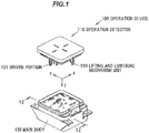
- FIG. 1 is a three-dimensional perspective view illustrating an overall configuration of an operation device according to an embodiment of the present invention.
- FIG. 2 is a cross-sectional view illustrating a driving unit of the operation device according to the embodiment of the present invention intersected at the YZ-plane of FIG. 1 .
- FIG. 3 is a three-dimensional perspective view illustrating the driving unit in entirety according to the embodiment of the present invention.
- FIG. 4 is a front view illustrating the driving unit according to the embodiment of the present invention viewed from a direction of a gear rotational axis.
- an operation device 100 is configured to include an operation detector 110, a lifting and lowering mechanism unit 120, a driving unit 200, a controller, and the like.
- the operation detector 110 detects operation performed by fingertips and the like.
- the lifting and lowering mechanism unit 120 allows the operation detector 110 to be lifted and lowered.
- the driving unit 200 is configured to drive the lifting and lowering mechanism unit 120 to provide a vibration to the operation detector 110, thereby providing a tactile sensation.
- the controller controls current flowing through the driving unit 200.
- the operation device 100 includes a main body 130, the lifting and lowering mechanism unit 120, and the driving unit 200.
- the lifting and lowering mechanism unit 120 is movably supported with respect to the main body 130 and includes a driven portion 121 configured to receive driving force for movement of the lifting and lowering mechanism unit 120.
- the driving unit 200 is attached to the main body 130 and configured to drive the lifting and lowering mechanism unit 120 by a driving pin 23 provided on a rotation gear.
- the lifting and lowering mechanism unit 120 is generally configured to include a groove portion 122 in which the driving pin 23 is accommodated into the driven portion 121 by rotation of the rotation gear upon the driving unit 200 being mounted in the main body 130.
- the operation detector 110 is a touch sensor that an operator touches with their fingertips and the like.
- the operation detector 110 is provided with the lifting and lowering mechanism unit 120.
- the operation detector 110 is movably supported by the lifting and lowering mechanism unit 120 in a vertical direction with respect to the main body 130.
- the driving unit 200 is mounted in the main body 130.
- the driving unit 200 is mounted in the main body 130 with the driving pin 23 movably engaging with the groove portion 122 of the lifting and lowering mechanism unit 120.
- the groove portion 122 is a cam groove defined in the driven portion 121 of the lifting and lowering mechanism unit 120. That is, as illustrated in FIG. 2 , a cam mechanism includes the driving pin 23, which engages with a groove portion (cam groove) having an undercut shape (U-like shape) defined in the driven portion 121 of the lifting and lowering mechanism unit 120.
- the operation device 100 has a configuration in which a predetermined tactile sensation is provided by vibration of the operation detector 110.
- the driving unit 200 includes a first gear 10 and a second gear 20.
- At least one of the first gear 10 and the second gear 20 is a fan-type gear.
- the first gear 10 and the second gear 20 are generally configured including guide portions 12, 22 in a gear rotation direction, respectively, when they are incorporated.
- the first gear 10 is a spur gear and made from resin such as polyoxymethylene/polyacetal (POM). As illustrated in FIG. 2 , the first gear 10 is formed as a fan-type gear including tooth portions (tooth projections) 10a at only predetermined range of the circumference of a pitch circle PC 1.
- POM polyoxymethylene/polyacetal
- An attachment hole 11 is defined in the first gear 10 at the rotation center thereof.
- the first gear 10 is attached to a motor shaft 51 of a motor 50 through the attachment hole 11.
- the motor shaft 51 fitted into the attachment hole 11 is integrated with the first gear 10 so that they will not rotate against each other. This configuration allows the first gear 10 to be driven and rotated by rotation of the motor 50.
- the second gear 20 is a spur gear and made from resin such as polyoxymethylene/polyacetal (POM). As illustrated in FIG. 2 , the second gear 20 is formed as a fan-type gear including tooth portions (tooth protrusion) 20a at only predetermined range of the circumference of a pitch circle PC2.
- POM polyoxymethylene/polyacetal
- An attachment hole 21 is defined in the second gear 20 at the rotation center.
- the second gear 20 is attached to a center shaft 70 that is provided upright from an attachment base 30, through the attachment hole 21.
- the center shaft 70 is rotatably fitted into the attachment hole 21. This configuration allows the second gear 20 to rotate about the attachment hole 21 (center shaft 70).
- the first gear 10 and the second gear 20 each have tooth portions formed with the same module.
- a distance between center shafts of the first gear 10 and the second gear 20 is substantially set to the sum of d 1 /2 (half of pitch circle diameter d 1 ) and d 2 /2 (half of pitch circle diameter d 2 ).
- this configuration allows the first gear 10 and the second gear 20 to transmit torque with the tooth portions meshing with each other.
- the second gear 20 driven by the first gear 10 can drive an object to be driven by the driving pin 23 provided on the second gear 20.
- the first gear 10 and the second gear 20 are a fan-type gear and incorporated with a specified pair of the teeth in a rotation direction being meshed with each other.
- the first gear 10 and the second gear 20 include a first guide portion 12 and a second guide portion 22, respectively, as a guide portion for position adjustment in a gear rotation direction during the incorporation of the first gear 10 and the second gear 20.
- the attachment base 30 is a base component, which supports the first gear 10 and the second gear 20 via the motor 50, the center shaft 70, and the like, thus constitutes the driving unit 200.
- the attachment base 30 is formed by pressing stainless steel, a treated steel plate, and the like.
- the attachment base 30 allows the driving unit 200 to be attached to the main body 130.
- the attachment base 30 is provided with attachment leg portions 32 on right and left sides.
- a guide groove 32a and an attachment hole 32b are defined in each of the attachment leg portions 32.
- the guide groove 32a is a groove for guiding the driving unit 200 to a guide portion 132 described below upon incorporating the driving unit 200 into the main body 130.
- the attachment hole 32b is a hole for fixing the driving unit 200 to an attachment boss portion 131 of the main body 130.
- a torsion spring 40 is attached to a boss portion 14 of the first gear 10 through a coil portion 41 thereof and applies biasing force on the first gear 10 in a predetermined rotation direction (A direction).
- the torsion spring 40 is formed from spring steel, stainless steel for a spring, and the like, and includes arm portions 42, 43 extending from both ends of the coil portion 41.
- one arm portion 42 of the torsion spring 40 is locked to a locking portion 61 of a block member 60 fixed to the attachment base 30.
- the other arm portion 43 is locked to a spring locking portion 13 that is a part of the first gear 10. This configuration allows the first gear 10 to be biased to rotate in the A direction.
- the motor 50 is fixed to the attachment base 30 by screws 80, 81 with the motor shaft 51 protruding to the side of a first gear 10.
- a DC brush motor, a DC brushless motor, or various motors may be utilized as the motor 50.
- the block member 60 is fixed to the attachment base 30 with the center shaft 70 being inserted into the attachment hole 62 and a leg portion 63 being locked to a cutout portion 31 of the attachment base 30.
- the block member 60 is formed from resin or the like.
- the block member 60 limits the movement of the second gear 20 in a direction of the center shaft 70 and prevents the second gear 20 from falling off from the center shaft 70.
- the block member 60 is also provided with the locking portion 61 to lock one arm portion 42 of the torsion spring 40. This configuration allows the first gear 10 to be biased to rotate in the A direction from an attachment base 30 side via the torsion spring 40.
- the main body 130 is a box formed from resin. As illustrated in FIG. 1 , the main body 130 supports the operation detector 110, and the lifting and lowering mechanism unit 120 in a vertical direction, which is the lifting-and-lowering direction. As illustrated in FIG. 2 , the driving unit 200 is attached and fixed to the main body 130 by a predetermined incorporating procedure.
- the attachment boss portion 131 and the guide portion 132 are formed in the main body 130.
- the attachment boss portion 131 is a portion for fixing the attachment base 30 at a predetermined vertical position.
- the guide portion 132 is a portion for movably guiding the driving unit 200 only in a vertical direction during the incorporation of the driving unit 200 into the main body 130.
- FIGS. 5A to 5C are process charts illustrating incorporation steps during the incorporation of the driving unit into the lifting and lowering mechanism unit.
- a method for manufacturing an operation device 100 is configured including the steps of:
- the lifting and lowering mechanism unit 120 provided with the driven portion 121 and the driving unit 200 are prepared.
- the lifting and lowering mechanism unit 120 is attached to the main body 130.
- the driving unit 200 is completed as a unit illustrated in FIGS. 3 and 4 .
- the torsion spring 40 is mounted in the driving unit 200, and the first gear 10 and the second gear 20 are biased to rotate in the A direction and the B direction, respectively.
- the driving unit 200 is in a fully assembled state as a unit in which the second guide portion 22 comes into contact with a plate face 30a of the attachment base 30.
- FIG. 5A is a view illustrating a state in which the driving unit 200 is positioned in the lifting and lowering mechanism unit 120 prepared in the preparation step P1 at the start of the incorporation step.
- the guide groove 32a of the attachment leg portion 32 of the driving unit 200 is positioned to the guide portion 132 of the main body 130. This allows the driving unit 200 to be incorporated in the upward direction without moving in a right and left direction illustrated in FIG. 5A .
- the driving pin 23 of the driving unit 200 is in contact with an edge 122a connected to the groove portion 122 of the driven portion 121.
- the driving pin 23 vertically moves in a linear movement direction along the edge 122a.
- FIG. 5B is a view illustrating a state in which the driving unit 200 is moved upward along the guide portion 132. After the driving unit 200 is moved upward along the guide portion 132, the driving pin 23 comes into contact with an upper surface 122b of the groove portion 122 of the driven portion 121. In this state, the attachment leg portion 32 is not in contact with the attachment boss portion 131. In this state, the second gear 20 is biased to rotate in the B direction and the driving pin 23 provided upright on the second gear 20 is in contact with the upper surface 122b while biased to move to the upper surface 122b.
- FIG. 5C is a view illustrating a state in which the driving unit 200 is further moved upward along the guide portion 132 and the attachment leg portion 32 is in contact with the attachment boss portion 131. From a state illustrated in FIG. 5B to a state illustrated in FIG. 5C , the driving pin 23 is moved along the groove portion 122 and rotates while resisting the force from the second gear 20 whose rotation is biased. And the driving pin 23 is accommodated deep into the groove portion 122. This constitutes a cam mechanism.
- the driving pin 23 is accommodated in the groove portion 122 of the driven portion 121 at a predetermined position and engaged with the groove portion 122 (cam groove) having an undercut shape (U-like shape) defined in the driven portion 121 of the lifting and lowering mechanism unit 120.
- the attachment leg portion 32 is fixed to the attachment boss portion 131 by a screw 82.
- An operation for incorporation of the driving unit 200 into the lifting and lowering mechanism unit 120 (driven portion 121) is completed by the above described steps P1 to P4.
Landscapes
- Engineering & Computer Science (AREA)
- General Engineering & Computer Science (AREA)
- Theoretical Computer Science (AREA)
- Physics & Mathematics (AREA)
- General Physics & Mathematics (AREA)
- Mechanical Engineering (AREA)
- Human Computer Interaction (AREA)
- Automation & Control Theory (AREA)
- Transmission Devices (AREA)
- User Interface Of Digital Computer (AREA)
Abstract
Description
- The present invention relates to an operation device and a method for manufacturing the same.
- An operation device has been proposed. The operation device includes an operation detector, a lifting and lowering mechanism unit, a driving unit, and a controller. The operation detector detects operation performed by fingertips and the like. The lifting and lowering mechanism unit allows the operation detector to be lifted and lowered. The driving unit drives the lifting and lowering mechanism unit to vibrate the operation detector. As a result, a tactile sensation is provided. The controller controls current flowing through the driving unit (see Patent Document 1, for example).
- In the operation device described in Patent Document 1 above, the operation detector is supported to the main body via the lifting and lowering mechanism unit while the driving unit including a gear mechanism is attached to the main body. The lifting and lowering mechanism unit includes a groove portion having an undercut shape. A protrusion of the driving unit is incorporated into the groove portion. A cam mechanism includes the groove portion of the lifting and lowering mechanism unit and the protrusion of the driving unit. The cam mechanism provides a configuration in which the driving unit drives the protrusion of the driving unit to vibrate the operation detector via the groove portion of the lifting and lowering mechanism unit. As a result, a predetermined tactile sensation is provided.
- Patent Document 1: Japanese Unexamined Patent Application Publication No.
2014-146148A - However, the operation device according to Patent Document 1 has a problem in that the lifting and lowering mechanism unit includes the groove portion having an undercut shape, which degrades the workability when the driving unit is incorporated. That is, when the lifting and lowering mechanism unit is incorporated into the main body, and the protrusion of the driving unit is incorporated into the groove portion having an undercut shape (U-like shape) of the lifting and lowering mechanism unit, these components need to be diagonally incorporated, which results in uncertainty in the operation and difficulty in the incorporation process.
- It is an object of the present invention to provide an operation device that has excellent workability during installation of the driving unit into a lifting and lowering mechanism unit, as well as a method for manufacturing the operation device.
-
- [1] According to an embodiment of the invention, an operation device is provided that comprises:
- a main body;
- a lifting and lowering mechanism unit movably supported with respect to the main body and comprising a driven portion configured to receive driving force for movement of the lifting and lowering mechanism unit;
- a driving unit attached to the main body and configured to drive the lifting and lowering mechanism unit by a driving pin provided on a rotation gear,
- wherein the lifting and lowering mechanism unit comprises a groove portion into which the driving pin is accommodated by rotation of the rotation gear when the driving unit is mounted on the main body.
- [2] The operation device described in [1] above may be configured such that the main body includes a guide portion configured to guide the driving unit and allow the driving pin to move linearly in a linear movement direction with respect to the lifting and lowering mechanism unit when the driving unit is mounted into the main body.
- [3] The operation device described in [1] or [2] above may be configured such that the groove portion comprises an edge with which the driving pin comes into contact when the driving pin moves in a linear movement direction.
- [4] The operation device described in any one of [1] to [3] above may be configured such that the driving pin is configured to be biased to move along the groove portion by the rotation gear that is biased to rotate in one direction.
- [5] According to an embodiment of the invention, a method for manufacturing an operation device is provided that comprises:
- providing a main body, a lifting and lowering mechanism unit movably supported with respect to the main body and comprising a driven portion configured to receive driving force for movement of the lifting and lowering mechanism unit, and a driving unit attached to the main body and configured to drive the lifting and lowering mechanism unit by a driving pin provided on a rotation gear;
- installing the lifting and lowering mechanism unit into the main body;
- installing the driving unit by linear movement of the driving unit with respect to the lifting and lowering mechanism unit; and
- installing the driving pin by movement of the driving pin along the groove portion of the lifting and lowering mechanism unit by the rotation gear that is biased to rotate in one direction such that the driving pin is accommodated in the groove portion.
- [6] The method according to [5] may be configured such that the main body comprises a guide portion configured to guide the driving unit so as to allow the driving unit to move linearly with respect to the lifting and lowering mechanism unit in the installing of the lifting and lowering mechanism unit.
- [7] The method according to [5] or [6] may be configured such that the groove portion comprises an edge with which the driving pin comes into contact while moving in a linear movement direction in the installing of the lifting and lowering mechanism unit.
- [8] The method according to any one of [5] to [7] may be configured such that the driving pin is accommodated in the groove portion by being rotated opposite to the one direction in which the rotation gear is biased to rotate in the installing of the driving pin. Advantageous Effects of Invention
- According to an embodiment of the invention, an operation device can be provided that has excellent workability during installation of a driving unit into a lifting and lowering mechanism, as well as a method for manufacturing the operation device.
-
-
FIG. 1 is a three-dimensional perspective view illustrating an overall configuration of an operation device according to an embodiment of the present invention. -
FIG. 2 is a cross-sectional view illustrating a driving unit of the operation device according to the embodiment of the present invention intersected at the YZ-plane ofFIG. 1 . -
FIG. 3 is a three-dimensional perspective view illustrating the driving unit in entirety according to the embodiment of the present invention. -
FIG. 4 is a front view illustrating the driving unit according to the embodiment of the present invention viewed from a direction of a gear rotational axis. -
FIGS. 5A to 5C are process charts illustrating incorporation steps during the incorporation of the driving unit into the lifting and lowering mechanism unit. -
FIG. 1 is a three-dimensional perspective view illustrating an overall configuration of an operation device according to an embodiment of the present invention.FIG. 2 is a cross-sectional view illustrating a driving unit of the operation device according to the embodiment of the present invention intersected at the YZ-plane ofFIG. 1 .FIG. 3 is a three-dimensional perspective view illustrating the driving unit in entirety according to the embodiment of the present invention.FIG. 4 is a front view illustrating the driving unit according to the embodiment of the present invention viewed from a direction of a gear rotational axis. The following describes preferred embodiments of the present invention in detail with reference to the drawings. - As illustrated in
FIGS. 1 and2 , anoperation device 100 is configured to include anoperation detector 110, a lifting andlowering mechanism unit 120, adriving unit 200, a controller, and the like. Theoperation detector 110 detects operation performed by fingertips and the like. The lifting andlowering mechanism unit 120 allows theoperation detector 110 to be lifted and lowered. Thedriving unit 200 is configured to drive the lifting andlowering mechanism unit 120 to provide a vibration to theoperation detector 110, thereby providing a tactile sensation. The controller controls current flowing through thedriving unit 200. - The
operation device 100 according to the embodiment of the present invention includes amain body 130, the lifting andlowering mechanism unit 120, and thedriving unit 200. The lifting andlowering mechanism unit 120 is movably supported with respect to themain body 130 and includes a drivenportion 121 configured to receive driving force for movement of the lifting andlowering mechanism unit 120. Thedriving unit 200 is attached to themain body 130 and configured to drive the lifting andlowering mechanism unit 120 by a drivingpin 23 provided on a rotation gear. The lifting andlowering mechanism unit 120 is generally configured to include agroove portion 122 in which the drivingpin 23 is accommodated into the drivenportion 121 by rotation of the rotation gear upon thedriving unit 200 being mounted in themain body 130. - As illustrated in
FIG. 1 , theoperation detector 110 is a touch sensor that an operator touches with their fingertips and the like. Theoperation detector 110 is provided with the lifting and loweringmechanism unit 120. Theoperation detector 110 is movably supported by the lifting and loweringmechanism unit 120 in a vertical direction with respect to themain body 130. - Meanwhile, as illustrated in
FIGS. 2 and3 , the drivingunit 200 is mounted in themain body 130. As illustrated inFIG. 2 , the drivingunit 200 is mounted in themain body 130 with the drivingpin 23 movably engaging with thegroove portion 122 of the lifting and loweringmechanism unit 120. Thegroove portion 122 is a cam groove defined in the drivenportion 121 of the lifting and loweringmechanism unit 120. That is, as illustrated inFIG. 2 , a cam mechanism includes the drivingpin 23, which engages with a groove portion (cam groove) having an undercut shape (U-like shape) defined in the drivenportion 121 of the lifting and loweringmechanism unit 120. In such a cam mechanism, driving the drivingpin 23 of thedriving unit 200 moves the drivenportion 121 vertically via the groove portion 122 (cam groove), then moves the lifting and loweringmechanism unit 120 and theoperation detector 110 vertically. In this way, theoperation device 100 has a configuration in which a predetermined tactile sensation is provided by vibration of theoperation detector 110. - As illustrated in
FIGS. 2 ,3 , and4 , the drivingunit 200 includes afirst gear 10 and asecond gear 20. Thesecond gear 20, which meshes with thefirst gear 10, transmits torque to thefirst gear 10. At least one of thefirst gear 10 and thesecond gear 20 is a fan-type gear. Thefirst gear 10 and thesecond gear 20 are generally configured includingguide portions 12, 22 in a gear rotation direction, respectively, when they are incorporated. - As illustrated in
FIGS. 3 and4 , thefirst gear 10 is a spur gear and made from resin such as polyoxymethylene/polyacetal (POM). As illustrated inFIG. 2 , thefirst gear 10 is formed as a fan-type gear including tooth portions (tooth projections) 10a at only predetermined range of the circumference of a pitch circle PC 1. - An
attachment hole 11 is defined in thefirst gear 10 at the rotation center thereof. Thefirst gear 10 is attached to amotor shaft 51 of amotor 50 through theattachment hole 11. Themotor shaft 51 fitted into theattachment hole 11 is integrated with thefirst gear 10 so that they will not rotate against each other. This configuration allows thefirst gear 10 to be driven and rotated by rotation of themotor 50. - As illustrated in
FIGS. 3 and4 , thesecond gear 20 is a spur gear and made from resin such as polyoxymethylene/polyacetal (POM). As illustrated inFIG. 2 , thesecond gear 20 is formed as a fan-type gear including tooth portions (tooth protrusion) 20a at only predetermined range of the circumference of a pitch circle PC2. - An
attachment hole 21 is defined in thesecond gear 20 at the rotation center. Thesecond gear 20 is attached to acenter shaft 70 that is provided upright from anattachment base 30, through theattachment hole 21. Thecenter shaft 70 is rotatably fitted into theattachment hole 21. This configuration allows thesecond gear 20 to rotate about the attachment hole 21 (center shaft 70). - The
first gear 10 and thesecond gear 20 each have tooth portions formed with the same module. As illustrated inFIG. 4 , a distance between center shafts of thefirst gear 10 and thesecond gear 20 is substantially set to the sum of d1/2 (half of pitch circle diameter d1) and d2/2 (half of pitch circle diameter d2). As illustrated inFIGS. 3 and4 , this configuration allows thefirst gear 10 and thesecond gear 20 to transmit torque with the tooth portions meshing with each other. - The
second gear 20 driven by thefirst gear 10 can drive an object to be driven by the drivingpin 23 provided on thesecond gear 20. - As illustrated in
FIG. 4 , thefirst gear 10 and thesecond gear 20 are a fan-type gear and incorporated with a specified pair of the teeth in a rotation direction being meshed with each other. As such, thefirst gear 10 and thesecond gear 20 include afirst guide portion 12 and a second guide portion 22, respectively, as a guide portion for position adjustment in a gear rotation direction during the incorporation of thefirst gear 10 and thesecond gear 20. - As illustrated in
FIGS. 3 and4 , theattachment base 30 is a base component, which supports thefirst gear 10 and thesecond gear 20 via themotor 50, thecenter shaft 70, and the like, thus constitutes the drivingunit 200. For example, theattachment base 30 is formed by pressing stainless steel, a treated steel plate, and the like. - As illustrated in
FIG. 2 , theattachment base 30 allows the drivingunit 200 to be attached to themain body 130. As such, as illustrated inFIG. 3 , theattachment base 30 is provided withattachment leg portions 32 on right and left sides. Aguide groove 32a and anattachment hole 32b are defined in each of theattachment leg portions 32. Theguide groove 32a is a groove for guiding thedriving unit 200 to aguide portion 132 described below upon incorporating thedriving unit 200 into themain body 130. Theattachment hole 32b is a hole for fixing thedriving unit 200 to anattachment boss portion 131 of themain body 130. - As illustrated in
FIGS. 3 and4 , atorsion spring 40 is attached to aboss portion 14 of thefirst gear 10 through acoil portion 41 thereof and applies biasing force on thefirst gear 10 in a predetermined rotation direction (A direction). Thetorsion spring 40 is formed from spring steel, stainless steel for a spring, and the like, and includesarm portions coil portion 41. - As illustrated in
FIG. 3 , onearm portion 42 of thetorsion spring 40 is locked to a lockingportion 61 of ablock member 60 fixed to theattachment base 30. Theother arm portion 43 is locked to aspring locking portion 13 that is a part of thefirst gear 10. This configuration allows thefirst gear 10 to be biased to rotate in the A direction. - As illustrated in
FIGS. 3 and4 , themotor 50 is fixed to theattachment base 30 byscrews motor shaft 51 protruding to the side of afirst gear 10. A DC brush motor, a DC brushless motor, or various motors may be utilized as themotor 50. - As illustrated in
FIG. 3 , theblock member 60 is fixed to theattachment base 30 with thecenter shaft 70 being inserted into theattachment hole 62 and aleg portion 63 being locked to acutout portion 31 of theattachment base 30. For example, theblock member 60 is formed from resin or the like. Theblock member 60 limits the movement of thesecond gear 20 in a direction of thecenter shaft 70 and prevents thesecond gear 20 from falling off from thecenter shaft 70. As described above, theblock member 60 is also provided with the lockingportion 61 to lock onearm portion 42 of thetorsion spring 40. This configuration allows thefirst gear 10 to be biased to rotate in the A direction from anattachment base 30 side via thetorsion spring 40. - As illustrated in
FIGS. 1 and2 , themain body 130 is a box formed from resin. As illustrated inFIG. 1 , themain body 130 supports theoperation detector 110, and the lifting and loweringmechanism unit 120 in a vertical direction, which is the lifting-and-lowering direction. As illustrated inFIG. 2 , the drivingunit 200 is attached and fixed to themain body 130 by a predetermined incorporating procedure. Theattachment boss portion 131 and theguide portion 132 are formed in themain body 130. Theattachment boss portion 131 is a portion for fixing theattachment base 30 at a predetermined vertical position. - The
guide portion 132 is a portion for movably guiding thedriving unit 200 only in a vertical direction during the incorporation of thedriving unit 200 into themain body 130. -
FIGS. 5A to 5C are process charts illustrating incorporation steps during the incorporation of the driving unit into the lifting and lowering mechanism unit. - A method for manufacturing an
operation device 100 is configured including the steps of: - (P1) preparing a
main body 130, a lifting and loweringmechanism unit 120 movably supported with respect to themain body 130 and including a drivenportion 121 configured to receive driving force for movement thereof, and adriving unit 200 attached to themain body 130 and configured to drive the lifting and loweringmechanism unit 120 by a drivingpin 23 provided on a rotation gear; - (P2) incorporating, into the
main body 130, the lifting and loweringmechanism unit 120 movably supported with respect to themain body 130 and including the drivenportion 121 configured to receive driving force for the movement thereof; - (P3) incorporating the
driving unit 200 into the lifting and loweringmechanism unit 120 by linear movement of thedriving unit 200 with respect to the lifting and loweringmechanism unit 120, and; - (P4) incorporating the driving
pin 23 by movement of the drivingpin 23 along thegroove portion 122 by the rotation gear that is biased to rotate in one direction by the step P3 of incorporating the driving unit so that the drivingpin 23 is accommodated in thegroove portion 122. - In the preparation step P1, the lifting and lowering
mechanism unit 120 provided with the drivenportion 121 and thedriving unit 200 are prepared. The lifting and loweringmechanism unit 120 is attached to themain body 130. Meanwhile, the drivingunit 200 is completed as a unit illustrated inFIGS. 3 and4 . Here, thetorsion spring 40 is mounted in thedriving unit 200, and thefirst gear 10 and thesecond gear 20 are biased to rotate in the A direction and the B direction, respectively. The drivingunit 200 is in a fully assembled state as a unit in which the second guide portion 22 comes into contact with aplate face 30a of theattachment base 30. -
FIG. 5A is a view illustrating a state in which thedriving unit 200 is positioned in the lifting and loweringmechanism unit 120 prepared in the preparation step P1 at the start of the incorporation step. Theguide groove 32a of theattachment leg portion 32 of thedriving unit 200 is positioned to theguide portion 132 of themain body 130. This allows the drivingunit 200 to be incorporated in the upward direction without moving in a right and left direction illustrated inFIG. 5A . - As illustrated in
FIG. 5A , the drivingpin 23 of thedriving unit 200 is in contact with anedge 122a connected to thegroove portion 122 of the drivenportion 121. The drivingpin 23 vertically moves in a linear movement direction along theedge 122a. -
FIG. 5B is a view illustrating a state in which thedriving unit 200 is moved upward along theguide portion 132. After thedriving unit 200 is moved upward along theguide portion 132, the drivingpin 23 comes into contact with anupper surface 122b of thegroove portion 122 of the drivenportion 121. In this state, theattachment leg portion 32 is not in contact with theattachment boss portion 131. In this state, thesecond gear 20 is biased to rotate in the B direction and the drivingpin 23 provided upright on thesecond gear 20 is in contact with theupper surface 122b while biased to move to theupper surface 122b. -
FIG. 5C is a view illustrating a state in which thedriving unit 200 is further moved upward along theguide portion 132 and theattachment leg portion 32 is in contact with theattachment boss portion 131. From a state illustrated inFIG. 5B to a state illustrated inFIG. 5C , the drivingpin 23 is moved along thegroove portion 122 and rotates while resisting the force from thesecond gear 20 whose rotation is biased. And the drivingpin 23 is accommodated deep into thegroove portion 122. This constitutes a cam mechanism. In the cam mechanism, the drivingpin 23 is accommodated in thegroove portion 122 of the drivenportion 121 at a predetermined position and engaged with the groove portion 122 (cam groove) having an undercut shape (U-like shape) defined in the drivenportion 121 of the lifting and loweringmechanism unit 120. - In the above described state, the
attachment leg portion 32 is fixed to theattachment boss portion 131 by ascrew 82. An operation for incorporation of thedriving unit 200 into the lifting and lowering mechanism unit 120 (driven portion 121) is completed by the above described steps P1 to P4. - According to the embodiment of the present invention, the following effects are achieved:
- (1) The operation device according to the present embodiment includes a lifting and lowering
mechanism unit 120 and thedriving unit 200. The lifting and loweringmechanism unit 120 is movably supported with respect to themain body 130 and includes a drivenportion 121 configured to be subject to driving force for movement thereof. The drivingunit 200 is attached to themain body 130 and configured to drive the lifting and loweringmechanism unit 120 by a drivingpin 23 provided on a rotation gear. The lifting and loweringmechanism unit 120 is configured to include agroove portion 122 in which the drivingpin 23 is accommodated into the drivenportion 121 by rotation of the rotation gear upon thedriving unit 200 being mounted in themain body 130. This requires no diagonal incorporation even if the lifting and loweringmechanism unit 120 has a configuration including a groove portion having an undercut shape (U-like shape). - (2)This eliminates uncertainty in an operation, and difficulty in the incorporation process. Therefore, it is possible to provide an operation device with excellent workability in the case where a driving unit is incorporated into a lifting and lowering mechanism unit, and a method for manufacturing the same.
- As is clear from the above description, although a representative embodiment, a modified example, and drawings according to the present invention are exemplified, the scope of the invention according to the patent claims is not limited to the embodiment, modified example, and drawings described above. Accordingly, it should be understood that all combinations of the features described in the embodiment, modified example, and illustrated in the drawings described above are not necessary to solve the problem of the present invention.
Claims (8)
- An operation device, comprising:a main body;a lifting and lowering mechanism unit movably supported with respect to the main body and comprising a driven portion configured to receive driving force for movement of the lifting and lowering mechanism unit;a driving unit attached to the main body and configured to drive the lifting and lowering mechanism unit by a driving pin provided on a rotation gear,wherein the lifting and lowering mechanism unit comprises a groove portion into which the driving pin is accommodated by rotation of the rotation gear when the driving unit is mounted on the main body.
- The device according to claim 1, wherein the main body comprises a guide portion configured to guide the driving unit so as to allow the driving unit to move linearly with respect to the lifting and lowering mechanism unit when the driving unit is installed into the main body.
- The device according to claim 1 or 2, wherein the groove portion comprises an edge with which the driving pin comes into contact while moving in a linear movement direction.
- The device according to any one of claims 1 to 3, wherein the driving pin is configured to be biased to move along the groove portion by the rotation gear that is biased to rotate in one direction.
- A method for manufacturing an operation device, comprising:providing a main body, a lifting and lowering mechanism unit movably supported with respect to the main body and comprising a driven portion configured to receive driving force for movement of the lifting and lowering mechanism unit, and a driving unit attached to the main body and configured to drive the lifting and lowering mechanism unit by a driving pin provided on a rotation gear;installing the lifting and lowering mechanism unit into the main body;installing the driving unit by linear movement of the driving unit with respect to the lifting and lowering mechanism unit; andinstalling the driving pin by movement of the driving pin along the groove portion of the lifting and lowering mechanism unit by the rotation gear that is biased to rotate in one direction such that the driving pin is accommodated in the groove portion.
- The method according to claim 5, wherein the main body comprises a guide portion configured to guide the driving unit so as to allow the driving unit to move linearly with respect to the lifting and lowering mechanism unit in the installing of the lifting and lowering mechanism unit.
- The method according to claim 5 or 6, wherein the groove portion comprises an edge with which the driving pin comes into contact while moving in a linear movement direction in the installing of the lifting and lowering mechanism unit.
- The method according to any one of claims 5 to 7, wherein the driving pin is accommodated in the groove portion by being rotated opposite to the one direction in which the rotation gear is biased to rotate in the installing of the driving pin.
Applications Claiming Priority (1)
| Application Number | Priority Date | Filing Date | Title |
|---|---|---|---|
| JP2016058377A JP6105116B1 (en) | 2016-03-23 | 2016-03-23 | Operating device and manufacturing method thereof |
Publications (2)
| Publication Number | Publication Date |
|---|---|
| EP3223117A1 true EP3223117A1 (en) | 2017-09-27 |
| EP3223117B1 EP3223117B1 (en) | 2018-05-23 |
Family
ID=58412907
Family Applications (1)
| Application Number | Title | Priority Date | Filing Date |
|---|---|---|---|
| EP17162454.7A Not-in-force EP3223117B1 (en) | 2016-03-23 | 2017-03-22 | Operation device and method for manufacturing the same |
Country Status (4)
| Country | Link |
|---|---|
| US (1) | US10613573B2 (en) |
| EP (1) | EP3223117B1 (en) |
| JP (1) | JP6105116B1 (en) |
| CN (1) | CN107450761B (en) |
Families Citing this family (1)
| Publication number | Priority date | Publication date | Assignee | Title |
|---|---|---|---|---|
| KR101913740B1 (en) * | 2017-08-30 | 2018-10-31 | 주식회사 디에스시동탄 | Seat cushion extension apparatus |
Citations (4)
| Publication number | Priority date | Publication date | Assignee | Title |
|---|---|---|---|---|
| JP2014146148A (en) | 2013-01-29 | 2014-08-14 | Tokai Rika Co Ltd | Tactile sense presentation device |
| JP2015045362A (en) * | 2013-08-28 | 2015-03-12 | 株式会社東海理化電機製作所 | Power transmission mechanism and input device equipped with the same |
| US20150077360A1 (en) * | 2012-04-12 | 2015-03-19 | Kabushiki Kaisha Tokai Rika Denki Seisakusho | Operation device |
| JP2016018414A (en) * | 2014-07-09 | 2016-02-01 | 株式会社東海理化電機製作所 | Input device |
Family Cites Families (19)
| Publication number | Priority date | Publication date | Assignee | Title |
|---|---|---|---|---|
| US1902448A (en) * | 1931-07-08 | 1933-03-21 | Horvath Anthony | Lifting jack |
| US2679357A (en) * | 1951-07-12 | 1954-05-25 | Westinghouse Electric Corp | Meter register |
| US3442146A (en) * | 1967-07-07 | 1969-05-06 | Theodore Simpson | Intermittent rotary motion |
| KR0122599B1 (en) * | 1988-06-22 | 1997-12-05 | 오까다 마사하루 | Coin receiving and discharging apparatus |
| JP3738029B2 (en) * | 1995-02-28 | 2006-01-25 | ジンテーズ アクチエンゲゼルシャフト,クール | Transmission device that converts rotational motion into reciprocating motion |
| US6115898A (en) * | 1995-06-06 | 2000-09-12 | Btm Corporation | Force multiplying apparatus for clamping a workpiece and forming a joint therein |
| US6623327B2 (en) * | 2000-08-11 | 2003-09-23 | Mattel, Inc. | Animated toy with Geneva mechanism |
| US20040089089A1 (en) * | 2002-11-08 | 2004-05-13 | Stevens Carlos J. | Anti-backlash method and system for multiple mesh gear train |
| JP5342949B2 (en) * | 2009-07-10 | 2013-11-13 | 株式会社 神崎高級工機製作所 | Pump for closed circuit configuration |
| JP5407693B2 (en) * | 2009-09-17 | 2014-02-05 | 旭硝子株式会社 | Glass substrate manufacturing method, polishing method and polishing apparatus, and glass substrate |
| KR101070320B1 (en) * | 2009-10-07 | 2011-10-06 | 김원태 | Transfomational device for circular arc exercise and that method |
| FR2967472B1 (en) * | 2009-12-22 | 2015-12-25 | Valeo Systemes De Controle Moteur | DEVICE FOR TRANSFORMING A ROTATION MOVEMENT INTO A TRANSLATION MOVEMENT |
| US8584541B2 (en) * | 2011-02-25 | 2013-11-19 | Delphi Technologies, Inc. | Anti-backlash/anti-rattle lever |
| CN202023892U (en) * | 2011-03-17 | 2011-11-02 | 信利仪器(汕尾)有限公司 | Inclined shaft eccentric driving device and cleaning brush |
| WO2012133456A1 (en) * | 2011-03-31 | 2012-10-04 | 本田技研工業株式会社 | Electrically powered brake device |
| US8998038B2 (en) * | 2012-03-27 | 2015-04-07 | Hsu-Hui Chang | Sprayer activation device |
| US8622259B2 (en) * | 2012-04-09 | 2014-01-07 | Hsu-Hui Chang | Electrical valve control device |
| EP2835280A1 (en) * | 2013-08-07 | 2015-02-11 | Schukra Gerätebau GmbH | Latch release actuator and method of actuating a seat latch |
| US9171566B2 (en) * | 2014-03-13 | 2015-10-27 | Oracle International Corporation | Buckling mechanism for a tape drive loader |
-
2016
- 2016-03-23 JP JP2016058377A patent/JP6105116B1/en active Active
-
2017
- 2017-03-13 US US15/457,320 patent/US10613573B2/en active Active
- 2017-03-15 CN CN201710153795.3A patent/CN107450761B/en active Active
- 2017-03-22 EP EP17162454.7A patent/EP3223117B1/en not_active Not-in-force
Patent Citations (4)
| Publication number | Priority date | Publication date | Assignee | Title |
|---|---|---|---|---|
| US20150077360A1 (en) * | 2012-04-12 | 2015-03-19 | Kabushiki Kaisha Tokai Rika Denki Seisakusho | Operation device |
| JP2014146148A (en) | 2013-01-29 | 2014-08-14 | Tokai Rika Co Ltd | Tactile sense presentation device |
| JP2015045362A (en) * | 2013-08-28 | 2015-03-12 | 株式会社東海理化電機製作所 | Power transmission mechanism and input device equipped with the same |
| JP2016018414A (en) * | 2014-07-09 | 2016-02-01 | 株式会社東海理化電機製作所 | Input device |
Also Published As
| Publication number | Publication date |
|---|---|
| CN107450761B (en) | 2020-07-10 |
| US20170277217A1 (en) | 2017-09-28 |
| JP2017174072A (en) | 2017-09-28 |
| CN107450761A (en) | 2017-12-08 |
| US10613573B2 (en) | 2020-04-07 |
| JP6105116B1 (en) | 2017-03-29 |
| EP3223117B1 (en) | 2018-05-23 |
Similar Documents
| Publication | Publication Date | Title |
|---|---|---|
| EP1598538B1 (en) | Electronically controlled throttle control apparatus | |
| US8136768B2 (en) | System and method for adjusting control surfaces for wind tunnel models | |
| KR101184423B1 (en) | Automatic gonio-stage | |
| EP1894877A2 (en) | Door drive for an automatic door | |
| CN102782239B (en) | Method for controlling a drive system of an adjusting element of a motor vehicle and corresponding drive system | |
| CN205618620U (en) | Accurate position adjustment device and ball thereof | |
| EP3300687B1 (en) | Electrically driven device | |
| AU2017381400B2 (en) | Camera control methods and apparatus | |
| AU2016398722B2 (en) | Gap Filler | |
| KR20140051060A (en) | Geared motor | |
| EP3223117B1 (en) | Operation device and method for manufacturing the same | |
| ITTO940091U1 (en) | ELECTROMECHANICAL ACTUATOR AND ENCLOSURE FOR SUPPORT AND CONTAINMENT. | |
| EP3254363A1 (en) | Drive unit for a wiper system | |
| EP3222880B1 (en) | Gear drive device | |
| DE102011000705A1 (en) | Height adjustment device of TV supported in furniture, has mounting carrier that is connected to base support through tension spring such that weight force acting on mounting carriage is compensated by spring | |
| DE102015201160A1 (en) | Brushless DC motor | |
| KR102205602B1 (en) | Positioning Pin for Serration Bar Jointed Seat Motor of Car | |
| US9221160B2 (en) | Motor mount | |
| CN210067942U (en) | Electric retractable door | |
| EP1604875B1 (en) | Device for the motorized movement of a safety belt in a motor vehicle | |
| CN219235359U (en) | Cutter mechanism and cutting machine | |
| CN214558308U (en) | A laser marking machine for rotary tiller | |
| CN218592946U (en) | High-precision guide rail device for driving and positioning | |
| CN211087273U (en) | Face recognition equipment | |
| DE102017129925A1 (en) | Electric motor structure with direct current for automotive applications of the type For the adjustment of seats, movement of window regulators and the like |
Legal Events
| Date | Code | Title | Description |
|---|---|---|---|
| PUAI | Public reference made under article 153(3) epc to a published international application that has entered the european phase |
Free format text: ORIGINAL CODE: 0009012 |
|
| STAA | Information on the status of an ep patent application or granted ep patent |
Free format text: STATUS: THE APPLICATION HAS BEEN PUBLISHED |
|
| AK | Designated contracting states |
Kind code of ref document: A1 Designated state(s): AL AT BE BG CH CY CZ DE DK EE ES FI FR GB GR HR HU IE IS IT LI LT LU LV MC MK MT NL NO PL PT RO RS SE SI SK SM TR |
|
| AX | Request for extension of the european patent |
Extension state: BA ME |
|
| STAA | Information on the status of an ep patent application or granted ep patent |
Free format text: STATUS: REQUEST FOR EXAMINATION WAS MADE |
|
| GRAJ | Information related to disapproval of communication of intention to grant by the applicant or resumption of examination proceedings by the epo deleted |
Free format text: ORIGINAL CODE: EPIDOSDIGR1 |
|
| STAA | Information on the status of an ep patent application or granted ep patent |
Free format text: STATUS: GRANT OF PATENT IS INTENDED |
|
| 17P | Request for examination filed |
Effective date: 20171030 |
|
| RBV | Designated contracting states (corrected) |
Designated state(s): AL AT BE BG CH CY CZ DE DK EE ES FI FR GB GR HR HU IE IS IT LI LT LU LV MC MK MT NL NO PL PT RO RS SE SI SK SM TR |
|
| GRAP | Despatch of communication of intention to grant a patent |
Free format text: ORIGINAL CODE: EPIDOSNIGR1 |
|
| INTG | Intention to grant announced |
Effective date: 20171213 |
|
| GRAS | Grant fee paid |
Free format text: ORIGINAL CODE: EPIDOSNIGR3 |
|
| GRAA | (expected) grant |
Free format text: ORIGINAL CODE: 0009210 |
|
| STAA | Information on the status of an ep patent application or granted ep patent |
Free format text: STATUS: THE PATENT HAS BEEN GRANTED |
|
| AK | Designated contracting states |
Kind code of ref document: B1 Designated state(s): AL AT BE BG CH CY CZ DE DK EE ES FI FR GB GR HR HU IE IS IT LI LT LU LV MC MK MT NL NO PL PT RO RS SE SI SK SM TR |
|
| REG | Reference to a national code |
Ref country code: GB Ref legal event code: FG4D |
|
| REG | Reference to a national code |
Ref country code: CH Ref legal event code: EP |
|
| REG | Reference to a national code |
Ref country code: IE Ref legal event code: FG4D |
|
| REG | Reference to a national code |
Ref country code: AT Ref legal event code: REF Ref document number: 1002015 Country of ref document: AT Kind code of ref document: T Effective date: 20180615 |
|
| REG | Reference to a national code |
Ref country code: DE Ref legal event code: R096 Ref document number: 602017000074 Country of ref document: DE |
|
| REG | Reference to a national code |
Ref country code: NL Ref legal event code: MP Effective date: 20180523 |
|
| REG | Reference to a national code |
Ref country code: LT Ref legal event code: MG4D |
|
| PG25 | Lapsed in a contracting state [announced via postgrant information from national office to epo] |
Ref country code: FI Free format text: LAPSE BECAUSE OF FAILURE TO SUBMIT A TRANSLATION OF THE DESCRIPTION OR TO PAY THE FEE WITHIN THE PRESCRIBED TIME-LIMIT Effective date: 20180523 Ref country code: BG Free format text: LAPSE BECAUSE OF FAILURE TO SUBMIT A TRANSLATION OF THE DESCRIPTION OR TO PAY THE FEE WITHIN THE PRESCRIBED TIME-LIMIT Effective date: 20180823 Ref country code: LT Free format text: LAPSE BECAUSE OF FAILURE TO SUBMIT A TRANSLATION OF THE DESCRIPTION OR TO PAY THE FEE WITHIN THE PRESCRIBED TIME-LIMIT Effective date: 20180523 Ref country code: NO Free format text: LAPSE BECAUSE OF FAILURE TO SUBMIT A TRANSLATION OF THE DESCRIPTION OR TO PAY THE FEE WITHIN THE PRESCRIBED TIME-LIMIT Effective date: 20180823 Ref country code: SE Free format text: LAPSE BECAUSE OF FAILURE TO SUBMIT A TRANSLATION OF THE DESCRIPTION OR TO PAY THE FEE WITHIN THE PRESCRIBED TIME-LIMIT Effective date: 20180523 |
|
| PG25 | Lapsed in a contracting state [announced via postgrant information from national office to epo] |
Ref country code: NL Free format text: LAPSE BECAUSE OF FAILURE TO SUBMIT A TRANSLATION OF THE DESCRIPTION OR TO PAY THE FEE WITHIN THE PRESCRIBED TIME-LIMIT Effective date: 20180523 Ref country code: RS Free format text: LAPSE BECAUSE OF FAILURE TO SUBMIT A TRANSLATION OF THE DESCRIPTION OR TO PAY THE FEE WITHIN THE PRESCRIBED TIME-LIMIT Effective date: 20180523 Ref country code: HR Free format text: LAPSE BECAUSE OF FAILURE TO SUBMIT A TRANSLATION OF THE DESCRIPTION OR TO PAY THE FEE WITHIN THE PRESCRIBED TIME-LIMIT Effective date: 20180523 Ref country code: GR Free format text: LAPSE BECAUSE OF FAILURE TO SUBMIT A TRANSLATION OF THE DESCRIPTION OR TO PAY THE FEE WITHIN THE PRESCRIBED TIME-LIMIT Effective date: 20180824 Ref country code: LV Free format text: LAPSE BECAUSE OF FAILURE TO SUBMIT A TRANSLATION OF THE DESCRIPTION OR TO PAY THE FEE WITHIN THE PRESCRIBED TIME-LIMIT Effective date: 20180523 |
|
| REG | Reference to a national code |
Ref country code: AT Ref legal event code: MK05 Ref document number: 1002015 Country of ref document: AT Kind code of ref document: T Effective date: 20180523 |
|
| PG25 | Lapsed in a contracting state [announced via postgrant information from national office to epo] |
Ref country code: CZ Free format text: LAPSE BECAUSE OF FAILURE TO SUBMIT A TRANSLATION OF THE DESCRIPTION OR TO PAY THE FEE WITHIN THE PRESCRIBED TIME-LIMIT Effective date: 20180523 Ref country code: RO Free format text: LAPSE BECAUSE OF FAILURE TO SUBMIT A TRANSLATION OF THE DESCRIPTION OR TO PAY THE FEE WITHIN THE PRESCRIBED TIME-LIMIT Effective date: 20180523 Ref country code: DK Free format text: LAPSE BECAUSE OF FAILURE TO SUBMIT A TRANSLATION OF THE DESCRIPTION OR TO PAY THE FEE WITHIN THE PRESCRIBED TIME-LIMIT Effective date: 20180523 Ref country code: SK Free format text: LAPSE BECAUSE OF FAILURE TO SUBMIT A TRANSLATION OF THE DESCRIPTION OR TO PAY THE FEE WITHIN THE PRESCRIBED TIME-LIMIT Effective date: 20180523 Ref country code: EE Free format text: LAPSE BECAUSE OF FAILURE TO SUBMIT A TRANSLATION OF THE DESCRIPTION OR TO PAY THE FEE WITHIN THE PRESCRIBED TIME-LIMIT Effective date: 20180523 Ref country code: AT Free format text: LAPSE BECAUSE OF FAILURE TO SUBMIT A TRANSLATION OF THE DESCRIPTION OR TO PAY THE FEE WITHIN THE PRESCRIBED TIME-LIMIT Effective date: 20180523 Ref country code: PL Free format text: LAPSE BECAUSE OF FAILURE TO SUBMIT A TRANSLATION OF THE DESCRIPTION OR TO PAY THE FEE WITHIN THE PRESCRIBED TIME-LIMIT Effective date: 20180523 |
|
| REG | Reference to a national code |
Ref country code: DE Ref legal event code: R097 Ref document number: 602017000074 Country of ref document: DE |
|
| PG25 | Lapsed in a contracting state [announced via postgrant information from national office to epo] |
Ref country code: SM Free format text: LAPSE BECAUSE OF FAILURE TO SUBMIT A TRANSLATION OF THE DESCRIPTION OR TO PAY THE FEE WITHIN THE PRESCRIBED TIME-LIMIT Effective date: 20180523 Ref country code: IT Free format text: LAPSE BECAUSE OF FAILURE TO SUBMIT A TRANSLATION OF THE DESCRIPTION OR TO PAY THE FEE WITHIN THE PRESCRIBED TIME-LIMIT Effective date: 20180523 |
|
| PLBE | No opposition filed within time limit |
Free format text: ORIGINAL CODE: 0009261 |
|
| STAA | Information on the status of an ep patent application or granted ep patent |
Free format text: STATUS: NO OPPOSITION FILED WITHIN TIME LIMIT |
|
| 26N | No opposition filed |
Effective date: 20190226 |
|
| PG25 | Lapsed in a contracting state [announced via postgrant information from national office to epo] |
Ref country code: ES Free format text: LAPSE BECAUSE OF FAILURE TO SUBMIT A TRANSLATION OF THE DESCRIPTION OR TO PAY THE FEE WITHIN THE PRESCRIBED TIME-LIMIT Effective date: 20180523 |
|
| PG25 | Lapsed in a contracting state [announced via postgrant information from national office to epo] |
Ref country code: MC Free format text: LAPSE BECAUSE OF FAILURE TO SUBMIT A TRANSLATION OF THE DESCRIPTION OR TO PAY THE FEE WITHIN THE PRESCRIBED TIME-LIMIT Effective date: 20180523 |
|
| PG25 | Lapsed in a contracting state [announced via postgrant information from national office to epo] |
Ref country code: LU Free format text: LAPSE BECAUSE OF NON-PAYMENT OF DUE FEES Effective date: 20190322 Ref country code: AL Free format text: LAPSE BECAUSE OF FAILURE TO SUBMIT A TRANSLATION OF THE DESCRIPTION OR TO PAY THE FEE WITHIN THE PRESCRIBED TIME-LIMIT Effective date: 20180523 |
|
| REG | Reference to a national code |
Ref country code: BE Ref legal event code: MM Effective date: 20190331 |
|
| PG25 | Lapsed in a contracting state [announced via postgrant information from national office to epo] |
Ref country code: IE Free format text: LAPSE BECAUSE OF NON-PAYMENT OF DUE FEES Effective date: 20190322 |
|
| PG25 | Lapsed in a contracting state [announced via postgrant information from national office to epo] |
Ref country code: BE Free format text: LAPSE BECAUSE OF NON-PAYMENT OF DUE FEES Effective date: 20190331 |
|
| PG25 | Lapsed in a contracting state [announced via postgrant information from national office to epo] |
Ref country code: TR Free format text: LAPSE BECAUSE OF FAILURE TO SUBMIT A TRANSLATION OF THE DESCRIPTION OR TO PAY THE FEE WITHIN THE PRESCRIBED TIME-LIMIT Effective date: 20180523 |
|
| PG25 | Lapsed in a contracting state [announced via postgrant information from national office to epo] |
Ref country code: PT Free format text: LAPSE BECAUSE OF FAILURE TO SUBMIT A TRANSLATION OF THE DESCRIPTION OR TO PAY THE FEE WITHIN THE PRESCRIBED TIME-LIMIT Effective date: 20180924 Ref country code: MT Free format text: LAPSE BECAUSE OF NON-PAYMENT OF DUE FEES Effective date: 20190322 |
|
| PGFP | Annual fee paid to national office [announced via postgrant information from national office to epo] |
Ref country code: FR Payment date: 20200214 Year of fee payment: 4 |
|
| REG | Reference to a national code |
Ref country code: CH Ref legal event code: PL |
|
| PG25 | Lapsed in a contracting state [announced via postgrant information from national office to epo] |
Ref country code: CH Free format text: LAPSE BECAUSE OF NON-PAYMENT OF DUE FEES Effective date: 20200331 Ref country code: LI Free format text: LAPSE BECAUSE OF NON-PAYMENT OF DUE FEES Effective date: 20200331 |
|
| PG25 | Lapsed in a contracting state [announced via postgrant information from national office to epo] |
Ref country code: CY Free format text: LAPSE BECAUSE OF FAILURE TO SUBMIT A TRANSLATION OF THE DESCRIPTION OR TO PAY THE FEE WITHIN THE PRESCRIBED TIME-LIMIT Effective date: 20180523 |
|
| PG25 | Lapsed in a contracting state [announced via postgrant information from national office to epo] |
Ref country code: IS Free format text: LAPSE BECAUSE OF FAILURE TO SUBMIT A TRANSLATION OF THE DESCRIPTION OR TO PAY THE FEE WITHIN THE PRESCRIBED TIME-LIMIT Effective date: 20180923 |
|
| PG25 | Lapsed in a contracting state [announced via postgrant information from national office to epo] |
Ref country code: HU Free format text: LAPSE BECAUSE OF FAILURE TO SUBMIT A TRANSLATION OF THE DESCRIPTION OR TO PAY THE FEE WITHIN THE PRESCRIBED TIME-LIMIT; INVALID AB INITIO Effective date: 20170322 |
|
| PG25 | Lapsed in a contracting state [announced via postgrant information from national office to epo] |
Ref country code: SI Free format text: LAPSE BECAUSE OF FAILURE TO SUBMIT A TRANSLATION OF THE DESCRIPTION OR TO PAY THE FEE WITHIN THE PRESCRIBED TIME-LIMIT Effective date: 20180523 |
|
| GBPC | Gb: european patent ceased through non-payment of renewal fee |
Effective date: 20210322 |
|
| PG25 | Lapsed in a contracting state [announced via postgrant information from national office to epo] |
Ref country code: FR Free format text: LAPSE BECAUSE OF NON-PAYMENT OF DUE FEES Effective date: 20210331 Ref country code: GB Free format text: LAPSE BECAUSE OF NON-PAYMENT OF DUE FEES Effective date: 20210322 |
|
| PG25 | Lapsed in a contracting state [announced via postgrant information from national office to epo] |
Ref country code: MK Free format text: LAPSE BECAUSE OF FAILURE TO SUBMIT A TRANSLATION OF THE DESCRIPTION OR TO PAY THE FEE WITHIN THE PRESCRIBED TIME-LIMIT Effective date: 20180523 |
|
| PGFP | Annual fee paid to national office [announced via postgrant information from national office to epo] |
Ref country code: DE Payment date: 20230131 Year of fee payment: 7 |
|
| REG | Reference to a national code |
Ref country code: DE Ref legal event code: R119 Ref document number: 602017000074 Country of ref document: DE |
|
| PG25 | Lapsed in a contracting state [announced via postgrant information from national office to epo] |
Ref country code: DE Free format text: LAPSE BECAUSE OF NON-PAYMENT OF DUE FEES Effective date: 20241001 |
|
| PG25 | Lapsed in a contracting state [announced via postgrant information from national office to epo] |
Ref country code: DE Free format text: LAPSE BECAUSE OF NON-PAYMENT OF DUE FEES Effective date: 20241001 |