EP3223083A1 - Digital holography device and digital hologram generation method - Google Patents
Digital holography device and digital hologram generation method Download PDFInfo
- Publication number
- EP3223083A1 EP3223083A1 EP15863320.6A EP15863320A EP3223083A1 EP 3223083 A1 EP3223083 A1 EP 3223083A1 EP 15863320 A EP15863320 A EP 15863320A EP 3223083 A1 EP3223083 A1 EP 3223083A1
- Authority
- EP
- European Patent Office
- Prior art keywords
- wavelength
- hologram
- light
- max
- wavelengths
- Prior art date
- Legal status (The legal status is an assumption and is not a legal conclusion. Google has not performed a legal analysis and makes no representation as to the accuracy of the status listed.)
- Withdrawn
Links
Images




Classifications
-
- G—PHYSICS
- G03—PHOTOGRAPHY; CINEMATOGRAPHY; ANALOGOUS TECHNIQUES USING WAVES OTHER THAN OPTICAL WAVES; ELECTROGRAPHY; HOLOGRAPHY
- G03H—HOLOGRAPHIC PROCESSES OR APPARATUS
- G03H1/00—Holographic processes or apparatus using light, infrared or ultraviolet waves for obtaining holograms or for obtaining an image from them; Details peculiar thereto
- G03H1/04—Processes or apparatus for producing holograms
- G03H1/0443—Digital holography, i.e. recording holograms with digital recording means
-
- G—PHYSICS
- G03—PHOTOGRAPHY; CINEMATOGRAPHY; ANALOGOUS TECHNIQUES USING WAVES OTHER THAN OPTICAL WAVES; ELECTROGRAPHY; HOLOGRAPHY
- G03H—HOLOGRAPHIC PROCESSES OR APPARATUS
- G03H1/00—Holographic processes or apparatus using light, infrared or ultraviolet waves for obtaining holograms or for obtaining an image from them; Details peculiar thereto
- G03H1/0005—Adaptation of holography to specific applications
-
- G—PHYSICS
- G03—PHOTOGRAPHY; CINEMATOGRAPHY; ANALOGOUS TECHNIQUES USING WAVES OTHER THAN OPTICAL WAVES; ELECTROGRAPHY; HOLOGRAPHY
- G03H—HOLOGRAPHIC PROCESSES OR APPARATUS
- G03H1/00—Holographic processes or apparatus using light, infrared or ultraviolet waves for obtaining holograms or for obtaining an image from them; Details peculiar thereto
- G03H1/04—Processes or apparatus for producing holograms
- G03H1/0465—Particular recording light; Beam shape or geometry
-
- G—PHYSICS
- G03—PHOTOGRAPHY; CINEMATOGRAPHY; ANALOGOUS TECHNIQUES USING WAVES OTHER THAN OPTICAL WAVES; ELECTROGRAPHY; HOLOGRAPHY
- G03H—HOLOGRAPHIC PROCESSES OR APPARATUS
- G03H1/00—Holographic processes or apparatus using light, infrared or ultraviolet waves for obtaining holograms or for obtaining an image from them; Details peculiar thereto
- G03H1/04—Processes or apparatus for producing holograms
- G03H1/08—Synthesising holograms, i.e. holograms synthesized from objects or objects from holograms
- G03H1/0866—Digital holographic imaging, i.e. synthesizing holobjects from holograms
-
- G—PHYSICS
- G03—PHOTOGRAPHY; CINEMATOGRAPHY; ANALOGOUS TECHNIQUES USING WAVES OTHER THAN OPTICAL WAVES; ELECTROGRAPHY; HOLOGRAPHY
- G03H—HOLOGRAPHIC PROCESSES OR APPARATUS
- G03H1/00—Holographic processes or apparatus using light, infrared or ultraviolet waves for obtaining holograms or for obtaining an image from them; Details peculiar thereto
- G03H1/0005—Adaptation of holography to specific applications
- G03H2001/005—Adaptation of holography to specific applications in microscopy, e.g. digital holographic microscope [DHM]
-
- G—PHYSICS
- G03—PHOTOGRAPHY; CINEMATOGRAPHY; ANALOGOUS TECHNIQUES USING WAVES OTHER THAN OPTICAL WAVES; ELECTROGRAPHY; HOLOGRAPHY
- G03H—HOLOGRAPHIC PROCESSES OR APPARATUS
- G03H1/00—Holographic processes or apparatus using light, infrared or ultraviolet waves for obtaining holograms or for obtaining an image from them; Details peculiar thereto
- G03H1/04—Processes or apparatus for producing holograms
- G03H1/0443—Digital holography, i.e. recording holograms with digital recording means
- G03H2001/0447—In-line recording arrangement
-
- G—PHYSICS
- G03—PHOTOGRAPHY; CINEMATOGRAPHY; ANALOGOUS TECHNIQUES USING WAVES OTHER THAN OPTICAL WAVES; ELECTROGRAPHY; HOLOGRAPHY
- G03H—HOLOGRAPHIC PROCESSES OR APPARATUS
- G03H1/00—Holographic processes or apparatus using light, infrared or ultraviolet waves for obtaining holograms or for obtaining an image from them; Details peculiar thereto
- G03H1/26—Processes or apparatus specially adapted to produce multiple sub- holograms or to obtain images from them, e.g. multicolour technique
- G03H1/2645—Multiplexing processes, e.g. aperture, shift, or wavefront multiplexing
- G03H2001/266—Wavelength multiplexing
-
- G—PHYSICS
- G03—PHOTOGRAPHY; CINEMATOGRAPHY; ANALOGOUS TECHNIQUES USING WAVES OTHER THAN OPTICAL WAVES; ELECTROGRAPHY; HOLOGRAPHY
- G03H—HOLOGRAPHIC PROCESSES OR APPARATUS
- G03H2222/00—Light sources or light beam properties
- G03H2222/10—Spectral composition
- G03H2222/13—Multi-wavelengths wave with discontinuous wavelength ranges
-
- G—PHYSICS
- G03—PHOTOGRAPHY; CINEMATOGRAPHY; ANALOGOUS TECHNIQUES USING WAVES OTHER THAN OPTICAL WAVES; ELECTROGRAPHY; HOLOGRAPHY
- G03H—HOLOGRAPHIC PROCESSES OR APPARATUS
- G03H2222/00—Light sources or light beam properties
- G03H2222/34—Multiple light sources
-
- G—PHYSICS
- G03—PHOTOGRAPHY; CINEMATOGRAPHY; ANALOGOUS TECHNIQUES USING WAVES OTHER THAN OPTICAL WAVES; ELECTROGRAPHY; HOLOGRAPHY
- G03H—HOLOGRAPHIC PROCESSES OR APPARATUS
- G03H2226/00—Electro-optic or electronic components relating to digital holography
- G03H2226/02—Computing or processing means, e.g. digital signal processor [DSP]
Definitions
- the present invention relates to a digital holography device that calculates a reconstruction image of an object from a hologram recording an interference pattern between an object beam and a reference beam, and a generation method of digital hologram; and particularly relates to the digital holography device, and the generation method of digital hologram therefrom utilizing an aspect to calculates a phase information from multiple recorded (stored in memory) holograms.
- the digital holography can provide a reconstruction image of an object by performing a predetermined arithmetic processing based on an interference pattern (hologram) that the object beam, which is the beam from the light source and reflected on the object plane or transmits the object and the reference beam, which is the direct light beam from the same light source.
- the hologram is an image denoting the intensity distribution of the interfering light and such intensity distribution is given based on the amplitude difference and the phase difference between the object beam and the reference beam, in which both are complex wavefronts.
- the hologram cannot record a phase that is an imaginary part of the wave. Consequently, when the reconstruction image of the object is acquired based on the hologram, a false image (conjugate image) having a complex conjugate amplitude with the real image at the symmetrical position of the real image (expected reconstruction image) relative to the detection plane. When two images are superimposed, the visual recognition (visibility) of the real image decreases, so that a clear image of the observation target may not be obtained.
- Patent Document 1 discloses a calculation method to the phase information using a linear operation by imaging a plurality of holograms in which the phase of the reference beam shifts. According to the method disclosed in Patent Document 1, however, an optical system including the piezoelectric element, the mirror, the lens and so forth is needed and consequently, the structure of the apparatus per se becomes complex and sizable.
- non-Patent Document 1 reported that an in-line-type digital holography device was applicable to the method of phase restoration, in which no optical system was needed.
- multiple holograms having each different distance between the object and the detection plane are imaged as the object beam that is diffracted light with an object having a high optical transparency (e.g., cells) and the reference beam that is non-diffracted light transmitting such object.
- the phase information is calculated by repeatedly calculating the propagation and the reverse-propagation of the light wave between the object plane and the detection plane based on the imaged multiple holograms.
- a driving mechanism e.g., piezoelectric element and so forth
- the phase restoration method by repeat calculation of light wave propagation based on the hologram imaged using the respective wavelengths while changing the light wavelength of the light emitted from the light source in the multiple steps is proposed (non-Patent Document 2).
- the phase restoration can be achieved using the simple device system without requirement of a complex optical system and a driving system.
- Patent Document 1 JP Patent Published 10-268740
- a biomicroscope which is one of applications of digital holography technology, so far is mainly focused on being capable of observing the inside structure of a cell or a further extremely finer object. i.e., increasing the resolution.
- an induced pluripotent stem cell e.g., ES cells and iPS cells
- the culture state must be carefully monitored and double-checked because the high-quality cells must be cultured while sustaining such pluripotent property.
- a defect like flatting, adhering to the medium and differentiation to specific cells and so forth
- the observer must double-check everyday whether or not such a defect has taken place, and if such a defect appears, the defect must be removed.
- Such defect phenomenon taking place in the induced pluripotent stem cell culture is decided based on a relatively macro structure (i.e., a colony shape with volume including thickness) compared to the inside structure of cells.
- a relatively macro structure i.e., a colony shape with volume including thickness
- the inventor confirmed by computing that when the macro structure is observed applying the aspects of non-Patent Document 2, the above conjugate image is superimposed to the target area, so that the real image can be worsened to be recognized by eyes.
- the structure of the non-Patent Document 2 is appropriate to decide whether or not the incident of defect in the induced pluripotent stem cell culture takes place.
- non-Patent Document 2 a correlation coefficient of the estimated amplitude value between holograms due to a plurality of wavelengths is used as an evaluation benchmark for an approximate accuracy. For example, given the illumination light wavelengths is, however, almost identical when a plurality of holograms is imaged, the value of the correlation coefficient is large despite no phase restoration at all, so that it can be found that a good approximation is obtained. Accordingly, the correlation coefficient as the evaluation benchmark can be used as a rough indication of convergence of the repeated calculations, but such correlation coefficient is not accurate as the benchmark of the degree of accuracy for the phase restoration.
- the present invention is intending to solve the above problems and a purpose of the present invention is to provide a digital holography device and a method of generation of a hologram capable of reconstructing a clear image relative to observation targets having a different size each other in accordance with the purpose thereof.
- the inventor sets forth the outline of the method of improving a quality of the image of the observation target by a phase restoration of the object beam.
- a phase information calculation processing is an algorithm to estimate the phase of object beam by a lightwave propagation calculation based on a plurality of the imaged holograms.
- the inventor sets for an example. The detail of each step S5 is set forth later.
- the word "lightwave propagation” include both aspects of propagation and reverse propagation as set forth above unless otherwise specified particularly.
- E(x,y,0) is a complex amplitude distribution relative to the object plane
- E(x,y,z) is a complex amplitude distribution relative to the detection plane
- z is a propagation distance
- K is a wavenumber.
- the above mathematical formula (1) corresponds to that an object image, as a sum of the diffraction grating of a variety of pitches, can be obtained by a diffraction calculation.
- the diffraction angle ⁇ of the incident light to the diffraction grating is given by the mathematical formula (2).
- ⁇ is a wavelength and p is a pitch width of the grating.
- Mathematical Formula (2) ⁇ sin ⁇ 1 ⁇ p
- a dimensional ratio of each member is arbitrarily modified for convenience of explanation and may be different from each actual dimensional ratio.
- the fineness of the diffraction pitches corresponds to the fineness of the structure in the image.
- the fine structure e.g., intracellular structure
- the large structure e.g., a shape of the cell colony
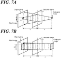
- FIG. 7A, FIG. 7B are schematic views illustrating a phenomenon in which a real image and a conjugate image reconstructed by a lightwave propagation calculation are superimposed to each other.
- the conjugate image having a fine structure corresponding to the high-frequency grating expands (defocuses) largely while reversely propagating to the object plane, so that an effect on visibility of the superimposed real image on the object plane can be minor.
- the conjugate image having a large structure corresponding to the low-frequency grating expands slightly, so that the lightwave can reaches to the object plane while keeping almost the same size as the real image. In such case, similar lines in the close proximity of each borderline of the real image are superimposed at the object plane, so that the visibility of the real image is largely worsened.
- the inventors set forth a wavelength condition of the illumination light to restore the phase of the low-frequency component.
- the diffraction angle of the low-frequency component is small compared to the high-frequency component, so that a shift length of the interference pattern due to diffraction is insubstantial when the difference of the light path between the detection planes H1 and H2 (d1 in FIG. 8 ).
- the shift length at d1 of the low-frequency component is too little to depict in FIG. compared to the shift length g1 in accordance with the high-frequency component).
- the difference between two holograms imaged at the detection planes H1 and H2 hardly appears, so that the phase restoration can be difficult. Therefore, referring to FIG. 8 , the light path difference between the detection planes H1 and H3 (d2 in FIG. 8 ) can be made long to increase the shift length (g2 relative to d2 in FIG. 8 ) of the interference pattern so that the phase of the low-frequency component can be easily restored.
- the plurality of detection planes is schematically illustrating the detection planes at the same location at which the illumination lights having a different wavelength are detected respectively; and the detection plane close to the object plane corresponds to the short-wavelength and the detection plane far therefrom corresponds to the long-wavelength.
- the light path difference ⁇ z AB that emerges, when two wavelengths ⁇ A and ⁇ B ( ⁇ A ⁇ ⁇ B ) are applied, is given by the following mathematical formula (3).
- the z is the propagation distance as well as in the mathematical formula (1).
- Mathematical Formula (3) ⁇ z AB z ⁇ ⁇ B ⁇ A ⁇ 1
- the phase of the component corresponds to the grating having the pitch width p lim satisfying the above mathematical formula (5) should be restored.
- the conjugate image having the fine structure expands larger than the conjugate image having rough structure, so that the effect of the high-frequency component having the narrower pitch width p than p lim can be deemed smaller if the phase of the component corresponding to the grating of the observation target p lim is restored.
- blow mathematical formula (7) is obtained from the above mathematical formula (6), ⁇ A , ⁇ B satisfying the mathematical formula (7) is the adequate wavelength of the illumination light to restore the phase of the component corresponding to p lim .
- Mathematical Formula (7) ⁇ B ⁇ A p lim 2 2 ⁇ z + 1
- Mathematical Formula (9) ⁇ max / ⁇ min ⁇ 1 / X + 1
- not disturb the visibility of the superimposed real image means, i.e., the particularly noticeable borderline (edge) in the real image is unequivocal.
- edge borderline
- the detector images a hologram, which is an interference pattern of an object beam due to the emitted coherent light from the light source and a reference beam.
- the above wavelength setting means that specifies the above plurality of wavelengths specifies the plurality of the wavelengths as the shortest wavelength ⁇ min and the longest wavelength ⁇ max satisfy the above expression.
- the relational expression is obtained from the mathematical formula (8).
- the mathematical formula (8) when the observation target is the structure corresponding to the diffraction grating having the pitch width p lim , if the magnification percentage of the conjugate image is X that does not worse the visibility of the real image (such value of magnification percentage X of the conjugate image is defined by the above finding while the user is considering the characteristics of the observation targets and provided to the device of the present invention), the proportion of the illumination light wavelengths ⁇ A and ⁇ B ( ⁇ A ⁇ ⁇ B ) is defined.
- the degree of accuracy of the phase restoration relative to the structure of the observation target can be improved.
- the conjugate image is enlarged more than X times as large as the real image, so that visibility of the real image may not be disturbed. Consequently, the clear image can be obtained even relative to relatively large observation target such as a cell colony.
- calculation of the phase information can be performed by the calculation means installed to the digital holography device or by an external computer for the control and analysis connected to the digital holography device.
- the wavelength setting means of the present invention can be one of functions subject to the light source or can be operative in the detector-side.
- the typical example of the former is the light source that can change the wavelength of the outgoing beam and one example of the latter can be a structure in which the detector is made of the hyperspectral camera and images of a plurality of wavelengths are individually extracted from the image that is imaged.
- an installed switching element connected to a plurality of light sources through such as an optical fiber and so forth may switch the outgoing beam from any one of light sources to be irradiated to the object.
- the above value corresponds to the case in which the area of the conjugate image is 10 times as large as the real image. Given the area ratio between the conjugate image and the real image is somewhat in such range, it is found that the visibility of the real image was satisfactory based on the results of the simulation performed by the inventor per se. At this time, ⁇ X is approximately 0.3 and the left-hand member of the formula (9) is approximately 1.3, so that the above expression can be obtained.
- the wavelength setting means specifies the shortest wavelength ⁇ min and the longest wavelength ⁇ max to satisfy the following expression.
- Mathematical Formula (11) 1.3 ⁇ ⁇ max / ⁇ min ⁇ 2.0
- the difference between the wavelengths is large, a part of diffraction beam is going out of the detect plane, e.g., as the high-frequency component in FIG. 8 relative to the detection plane H3, so that the degree of accuracy of the phase restoration can be dropped, accordingly. Therefore, the following criteria are adopted to determine an appropriate upper limit value of the ratio between the two wavelengths.
- a method of generation of a digital hologram according to the third invention for solving the above problems based on the principles set forth above comprises steps of: a) emitting a coherent light from a light source; b) imaging a hologram that is an interference pattern of an object beam and a reference beam due to the emitted light from the light source by a detector; and c) specifying a plurality of wavelengths of the illumination light that generates a hologram being imaged by the detector; wherein the plurality of wavelength that is specified by the wavelength specifying step based on a magnification percentage X set up by a user not to disturb visibility thereof when a real image reconstructed by the preset calculation means and the conjugate image relative to a structure of the observation targets are superimposed to the corresponding real image are set as the shortest wavelength ⁇ min and the longest wavelength ⁇ max satisfy the expression formula (12).
- Mathematical Formula (12) ⁇ max / ⁇ min ⁇ 1 / X + 1
- the phase image can be displayed without a fold of the phase as an advantage, but the resolution of the phase decreases as a disadvantage. Therefore, it is preferable to select appropriate wavelengths ⁇ A , ⁇ B in accordance with the phase range of the object.
- specifying the plurality of the wavelengths as 1.3 ⁇ ⁇ max / ⁇ min ⁇ 2.0 is an adequate condition when applying the phase unwrapping method.
- a clear image relative to the target structure can be reconstructed.
- the method according to the aspect of the present invention can be used even when the phase unwrapping method is applied.
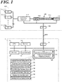
- FIG. 1 is a schematic block diagram illustrating a measurement system comprising a digital holography device according to the aspect of the Embodiment of the present invention.
- the measurement system comprises a digital holography device 100, a workstation 1 that is communicably connected to the digital holography device 100.
- the digital holography device 100 that is a microscope comprises the number N of laser diode (LD) 101(1)-101(N), a switching element 102 (corresponds to the wavelength setting means of the present invention), an irradiation element 103, a detector 104 and an interface (I/F) 105.
- Any LD101(1)-101(N) is a light source that oscillates and emits coherent beam and oscillation wavelengths ⁇ 1 - ⁇ N thereof are specified to be longer in order.
- Such LD101(1)-101(N) are connected to the switching element 102 via an optical fiber.
- the switching element 102 switches the LD101(1)-101(N), which is used as the light source of the illumination light 120, according to the directive from the workstation 1.
- the irradiation element 103 irradiates the illumination light 120, as specified above, toward the object 110.
- the illumination light 120 passes through the (culture) plate and culture medium other than the object 110, so such components should be also made of light transmissive material.
- the detector 104 images the interference pattern due to the illumination light 120 emitted from the irradiation element 103 as a hologram.
- the hologram is a record of the interference pattern emerging from the object beam (arc lines depicted in the right-side of the object 110 in FIG. 1 ) which is the light wave diffracted by the object 110 and the reference wave (straight lines in the right-side of the object 110) which is the not-diffracted light wave (including transmitted light).
- the detector 104 can be brought into reality by e.g., CCD (charge-coupled devices) image sensor.
- the workstation 1 is practically a true computer comprising a CPU (central processing unit) connecting a memory 12. a monitor made of LCD (liquid crystal display) and so forth, an input element 16 including a mouse and a memory storing element 20 each other.
- the above memory comprises a volatile memory such as RAM (random access memory), and the memory storing element 20 comprises non-volatile memory such as a ROM (read only memory), a flash memory, a EPROM (erasable programmable ROM), EEPROM® (electrically EPROM), a HDD (hard disc drive), a SSD (solid state drive) and so forth.
- An imaging control-data analysis program 21 is installed to the memory storing element 20. Each element that the imaging control-data analysis program 21 comprises is a feasible functional means when CPU 10 reads out the program into the memory 12 and execute.
- the memory storing element 20 stores OS (operating system) 29.
- the workstation 1 comprises an interface (I/F) 18 that is operative to connect directly to the outside devices and to the outside devices through a network such as a LAN (local area network), and connects to the digital holography device 100 through the network cable NW (or wireless LAN) from I/F18.
- a network such as a LAN (local area network)
- NW wireless LAN
- the workstation 1 can connect multiple digital holography devices 100.
- the workstation 1 can connect directly multiple digital holography devices 100 via USB cable and so forth.
- the imaging control-data analysis program 21 is an application software for controlling imaging by the digital holography device 100, reconstructing the image of the object 110 by the predetermined operation processing based on the imaged hologram, and displaying the reconstructed image on the monitor 14 as an image.
- the imaging control-data analysis program 21 needs not always be a simplex program, and can be a functional part of elements of the digital holography device 100.
- the inventor sets forth a flow of the processings executed by the measurement system including the digital holography device 100 according to the aspect of the present Embodiment.
- the inventor sets forth the flow of the basic processings executed by the imaging control-data analysis program 21.
- the user first is requested to input the value of the central wavelength ⁇ mid of the hologram imaging.
- the input value of the central wavelength ⁇ mid can be not only an arbitrary input value, but also any selected value of the number N of LD101(1)-101(N) pre-installed to the digital holography device 100 of the present invention.
- the imaging control-data analysis program 21 requests, subsequently, to input the value of the area magnification ratio X 2 of the conjugate image (magnification percentage X).
- the imaging parameter setting element 31 of the imaging control-data analysis program 21 selects a plurality of the LD light sources from the LD101(1)-101(N) as the central wavelength ⁇ mid to satisfy the above expression 9.
- the wavelength ⁇ J1 of LD101(n)-wavelength ⁇ J2 LD101(K2) satisfies ⁇ J 2 / ⁇ J 1 ⁇ 1 / X + 1 , average ( ⁇ J1 , ..., ⁇ J2 ) ⁇ ⁇ mid .
- the object 110 of the imaging target is a colony of the induced pluripotent stem cell such as ES cells and iPS cells and so forth.
- the inventor sets forth as given the value of the area magnification ratio X2 of the conjugate image is 10 ( ⁇ 10 as magnification percentage).
- the reason for the decision is that when the object 110 of the observation targets is the cell colony, the area between the real image and the superimposed conjugate image thereon, which is approximately 10 times as large as the real image, can be satisfactory to provide the clear shape-image based on the result of a preliminary experiment.
- the wavelength input by the user at the above step can be the shortest wavelength ⁇ min or the longest wavelength ⁇ max instead of the central wavelength ⁇ mid .
- a visible region (approximately 600nm) is appropriate to avoid a low wavelength region concerned about a toxicological effect or a far-infrared region concerned about heat generation due to absorption of light, but such value is not particularly an issue in regard to the below explanation.
- Step S14 a hologram imaging processing is executed (Step S14) following section of the light source to be used.
- Step S14 a hologram imaging processing is executed (Step S14) following section of the light source to be used.
- Step S101 J1(J1 ⁇ j ⁇ J2) is given (Step S101) and the imaging parameter setting element 31 specifies the wavelength of the illumination light 120 (referring to FIG. 1 ) emitted from the irradiation element 103 as ⁇ j (Step S102).
- the imaging directive element 32 directs the digital holography device 100 to image a hologram image of ⁇ j (Step S103).
- the above directive by the imaging directive element 32 is sent to an I/F105 of the digital holography device 100 from the I/F18 as the imaging directive signal (Step S104).
- the switching element 102 switched the light source for the illumination light 120 to the number j of LD101(j) (Step S105).
- the irradiation element 103 irradiates the illumination light 120 toward the object 110 (Step S106).
- the interference pattern between the diffracted object beam by the object 110 and the non-diffracted reference wave is imaged by the detector 104 (Step 107).
- the imaged hologram data is sent to the I/F18 of the workstation 1 via I/F/105 (Step 108).
- the hologram acquisition element 33 acquires the received hologram data and stores in the hologram memory storing element 37 (Step S109).
- the hologram memory storing element 37 collectively stores a plurality of hologram data (J2 - J1 + 1 according to the aspect of the present Embodiment) applied for the phase information calculation processing, set forth later, and reconstruction of the object image every measurement targets designated by the user.
- the imaging parameter setting element 31 increments j (Step S110) and unless the value j is beyond the maximum value J2 (Step 111), the processing turns back to right before the Step 102 and then the steps S102-S111 are executed relative to the next wavelength ⁇ j .
- the phase information calculation element 34 subsequently executes the phase information calculation processing to the respective hologram data (Step S15).
- the inventor sets forth the detail of the processing at the present step later referring to FIG. 4 .
- the image generation element 35 reconstructs the object image based on the hologram data following such phase restoration (Step S16).
- the reconstructed object image (hereafter reconstructed image) is displayed on the monitor 14 by the display control element 36 (Step S17).
- the general processings due to the measurement system complete.
- phase information calculation processing is executed based on the number (J2 - J1 + 1) of the hologram data stored in the hologram memory storing element 37 at the step 109.
- the phase information calculation element 34 converts each hologram to an amplitude image (Step 201).
- the hologram that is a distribution of intensity values, so the hologram cannot be applied to a Fourier transform used in the propagation calculation set forth later. Therefore, each intensity value is converted to an amplitude value at the present step.
- the conversion to the amplitude image is performed by calculation of the square root of each pixel value.
- the default value of the phase image can be arbitrarily and, for example, all pixel values can be specified as null or each pixel value can be specified randomly.
- j (1 ⁇ j ⁇ J2) is a discriminator of LD101, which is the light source of the illumination light 120, as well as set forth above, a is a direction value having either 1 or -1, and n (1 ⁇ n) is the repetition number of the operation.
- the phase information calculation element 34 calculates a reverse propagation to the object plane (Step S204).
- the phase information calculation element 34 determines whether or not a value of j + a is in the range of J1-J2 (Step S205).
- the value of j + a is 2 at the first test, so that the decision is "Yes” at the step S205 and consequently the j is incremented (Step S207).
- J the repetition of increment results in 5
- J the repetition of increment results in 5
- j + 1 is 6 that is over J2, so that decision at the step S205 results in "No”.
- the phase information calculation element 34 reverses plus and minus of a (Step S206) and decrements j (Step S207).
- phase information calculation element 34 updates the phase of the object beam due to ⁇ j (Step S208). Specifically, relative to the complex wavefront relative to the object plane calculated at the step S204, the phase is converted to the next wavelength (without updating the amplitude).
- Step S209 Under the condition in which only the phase is converted to the next wavelength, propagation to the detection plane is calculated (Step S209), and when the sum of differences (i.e., errors) between the calculation result and the actual measurement value, which is the square root of each intensity value of the hologram, is bigger than the threshold value ⁇ ("No" at the step S210), the phase information calculation element 34 increments n (Step S221) and repeats the above processings.
- the phase information calculation element 34 deems that the satisfactory phase restoration is obtained and ends the phase information calculation processing.
- Simulation results of the object images that are reconstructed according to the above method are illustrated in FIG. 5 .
- ⁇ max / ⁇ min ⁇ 1.3 is given, a remarkable phase restoration is observed.
- adequate light sources LD101(J1)-101(J2) from a number of laser diodes LD101(1)-101(N) corresponding to the central wavelength ⁇ mid (or the longest wavelength ⁇ max or the shortest wavelength ⁇ min ) and the magnification percentage X input by the user are selected and used by switching the light sources but such setting of freedom is not required and when an imaging (observation) target is pre-determined, only a plurality of light sources pre-registered according to the expression 9 is installed to the digital holography device 100 and only such light sources are allowed to be employed.
- the number of light sources (number of wavelengths) are set to 2 so that the calculation time is shortened, and when such defect of the cell colony and so forth is examined as set forth above, practically and satisfactorily clear image reconstruction can be accomplished.
Landscapes
- Physics & Mathematics (AREA)
- General Physics & Mathematics (AREA)
- Engineering & Computer Science (AREA)
- Computing Systems (AREA)
- Theoretical Computer Science (AREA)
- Holo Graphy (AREA)
Abstract
Description
- The present invention; relates to a digital holography device that calculates a reconstruction image of an object from a hologram recording an interference pattern between an object beam and a reference beam, and a generation method of digital hologram; and particularly relates to the digital holography device, and the generation method of digital hologram therefrom utilizing an aspect to calculates a phase information from multiple recorded (stored in memory) holograms.
- The digital holography can provide a reconstruction image of an object by performing a predetermined arithmetic processing based on an interference pattern (hologram) that the object beam, which is the beam from the light source and reflected on the object plane or transmits the object and the reference beam, which is the direct light beam from the same light source. The hologram is an image denoting the intensity distribution of the interfering light and such intensity distribution is given based on the amplitude difference and the phase difference between the object beam and the reference beam, in which both are complex wavefronts.
- However, the hologram cannot record a phase that is an imaginary part of the wave. Consequently, when the reconstruction image of the object is acquired based on the hologram, a false image (conjugate image) having a complex conjugate amplitude with the real image at the symmetrical position of the real image (expected reconstruction image) relative to the detection plane. When two images are superimposed, the visual recognition (visibility) of the real image decreases, so that a clear image of the observation target may not be obtained.
- A variety of approaches to restore the phase (inference of the phase information) of the object beam has been applied to solve the above issue. For example,
Patent Document 1 discloses a calculation method to the phase information using a linear operation by imaging a plurality of holograms in which the phase of the reference beam shifts. According to the method disclosed inPatent Document 1, however, an optical system including the piezoelectric element, the mirror, the lens and so forth is needed and consequently, the structure of the apparatus per se becomes complex and sizable. - On the other hand,
non-Patent Document 1 reported that an in-line-type digital holography device was applicable to the method of phase restoration, in which no optical system was needed. According to the above method, multiple holograms having each different distance between the object and the detection plane are imaged as the object beam that is diffracted light with an object having a high optical transparency (e.g., cells) and the reference beam that is non-diffracted light transmitting such object. Subsequently. the phase information is calculated by repeatedly calculating the propagation and the reverse-propagation of the light wave between the object plane and the detection plane based on the imaged multiple holograms. Regardless, even if the above method, a driving mechanism (e.g., piezoelectric element and so forth) to shift the detector in a high degree of accuracy is still required. - In contrast, recently, the phase restoration method by repeat calculation of light wave propagation based on the hologram imaged using the respective wavelengths while changing the light wavelength of the light emitted from the light source in the multiple steps is proposed (non-Patent Document 2). According to the above method, the phase restoration can be achieved using the simple device system without requirement of a complex optical system and a driving system.
- Patent Document 1:
JP Patent Published 10-268740 -
- Non-Patent
Document 1 Yan Zhang, et al., "Whole optical wave field reconstruction from double or multi in-line holograms by phase retrieval algorithm", Optic Express, The Optical Society of America, 2003, Vol. 11, No. 24, pp. 3234-3241 - Non-Patent
Document 2 Peng Bao, et al., "Lensless phase microscopy using phase retrieval with multiple illumination wavelengths", Applied Optics, The Optical Society of America, 2012, Vol. 51, No. 22, pp. 5486-5494 - A biomicroscope, which is one of applications of digital holography technology, so far is mainly focused on being capable of observing the inside structure of a cell or a further extremely finer object. i.e., increasing the resolution.
- In the regeneration medicine field in recent years, the researches applying an induced pluripotent stem cell (e.g., ES cells and iPS cells) are very active. In such researches, the culture state must be carefully monitored and double-checked because the high-quality cells must be cultured while sustaining such pluripotent property. For example, when a defect (like flatting, adhering to the medium and differentiation to specific cells and so forth) takes place in some cells of a colony, such a defect propagates to other cells and finally, all cells of the colony become defective. Accordingly, the observer must double-check everyday whether or not such a defect has taken place, and if such a defect appears, the defect must be removed. Although such double-checking can be carried out using a microscope, cells per se are hardly recognizable by eyes optically, and even if a phase-contrast microscope is employed, it is still hard to decide an incident of the defect, so that such work imposes a heavy burden to the observer. Therefore, such work is being tried to be carried out automatically using a digital holography technology.
- Such defect phenomenon taking place in the induced pluripotent stem cell culture is decided based on a relatively macro structure (i.e., a colony shape with volume including thickness) compared to the inside structure of cells. Now the inventor confirmed by computing that when the macro structure is observed applying the aspects of
non-Patent Document 2, the above conjugate image is superimposed to the target area, so that the real image can be worsened to be recognized by eyes. Specifically, it is hard to say the structure of thenon-Patent Document 2 is appropriate to decide whether or not the incident of defect in the induced pluripotent stem cell culture takes place. - In addition, even if the method described in
non-Patent Document 2, a complete restoration of the phase is difficult and a superimposition of conjugate images in the in-line-type digital holography is hardly avoidable. The reason is that the value eligible for an unequivocal benchmark indicating the degree of phase restoration is not defined. According tonon-Patent Document 2, a correlation coefficient of the estimated amplitude value between holograms due to a plurality of wavelengths is used as an evaluation benchmark for an approximate accuracy. For example, given the illumination light wavelengths is, however, almost identical when a plurality of holograms is imaged, the value of the correlation coefficient is large despite no phase restoration at all, so that it can be found that a good approximation is obtained. Accordingly, the correlation coefficient as the evaluation benchmark can be used as a rough indication of convergence of the repeated calculations, but such correlation coefficient is not accurate as the benchmark of the degree of accuracy for the phase restoration. - The present invention is intending to solve the above problems and a purpose of the present invention is to provide a digital holography device and a method of generation of a hologram capable of reconstructing a clear image relative to observation targets having a different size each other in accordance with the purpose thereof.
- Now, first, the inventor sets forth the outline of the method of improving a quality of the image of the observation target by a phase restoration of the object beam.
- A phase information calculation processing is an algorithm to estimate the phase of object beam by a lightwave propagation calculation based on a plurality of the imaged holograms. Referring to
FIG. 4 , the inventor sets for an example. The detail of each step S5 is set forth later. In addition, the word "lightwave propagation" include both aspects of propagation and reverse propagation as set forth above unless otherwise specified particularly. - The Fresnel diffraction equation and the angular spectrum method and so forth are known to calculate the lightwave propagation and the calculation formula of the angular spectrum method is given as
Mathematical Formula 1 below.
Mathematical Formula 1
- E(x,y,0) is a complex amplitude distribution relative to the object plane, E(x,y,z) is a complex amplitude distribution relative to the detection plane, and z is a propagation distance. In addition, K is a wavenumber.
- The above mathematical formula (1) corresponds to that an object image, as a sum of the diffraction grating of a variety of pitches, can be obtained by a diffraction calculation. The diffraction angle ϕ of the incident light to the diffraction grating is given by the mathematical formula (2). λ is a wavelength and p is a pitch width of the grating.
Mathematical Formula (2)
- If p is smaller than the value given by the above mathematical formula (2), i.e., the pitch of the diffraction grating is fine (p = p1), the diffraction angle Φ is large, so that the wavefront (object beam) is largely expanding in the perpendicular direction relative to the detection plane (left side of
FIG. 6 ). In contrast, if p is great, i.e., the pitch of the diffraction grating is rough (p = p2 > p1), the diffraction angle Φ is small, so that the wavefront is slightly expanding in the perpendicular direction relative to the detection plane (right side ofFIG. 6 ). Such behavior is the same as when the conjugate image reversely propagates from the detection plane to the wavefront. - In addition, in the FIGs referred in the specification of the present invention, a dimensional ratio of each member is arbitrarily modified for convenience of explanation and may be different from each actual dimensional ratio.
- Now, the fineness of the diffraction pitches corresponds to the fineness of the structure in the image. Specifically, the fine structure (e.g., intracellular structure) in the image is deemed as a high-frequency grating having fine pitches and the large structure (e.g., a shape of the cell colony) is deemed as a low-frequency grating having rough pitches.
-
FIG. 7A, FIG. 7B are schematic views illustrating a phenomenon in which a real image and a conjugate image reconstructed by a lightwave propagation calculation are superimposed to each other. Referring toFIG. 7A , the conjugate image having a fine structure corresponding to the high-frequency grating expands (defocuses) largely while reversely propagating to the object plane, so that an effect on visibility of the superimposed real image on the object plane can be minor. In contrast, referring toFIG. 7B , the conjugate image having a large structure corresponding to the low-frequency grating expands slightly, so that the lightwave can reaches to the object plane while keeping almost the same size as the real image. In such case, similar lines in the close proximity of each borderline of the real image are superimposed at the object plane, so that the visibility of the real image is largely worsened. - Based on the principle set forth above, when the structure of the observation targets is relatively large and the phase of the complex wavefront diffracted by the low-frequency grating (hereinafter low-frequency component; and a complex wavefront diffracted by the high-frequency grating is also called as high-frequency component) is restored, worsening of visibility of the real image can be suppressed.
- Here, the inventors set forth a wavelength condition of the illumination light to restore the phase of the low-frequency component. Referring to
FIG. 8 , the diffraction angle of the low-frequency component is small compared to the high-frequency component, so that a shift length of the interference pattern due to diffraction is insubstantial when the difference of the light path between the detection planes H1 and H2 (d1 inFIG. 8 ). (Referring toFIG. 8 , the shift length at d1 of the low-frequency component is too little to depict in FIG. compared to the shift length g1 in accordance with the high-frequency component). Under such condition, relative to the low-frequency component, the difference between two holograms imaged at the detection planes H1 and H2 hardly appears, so that the phase restoration can be difficult. Therefore, referring toFIG. 8 , the light path difference between the detection planes H1 and H3 (d2 inFIG. 8 ) can be made long to increase the shift length (g2 relative to d2 inFIG. 8 ) of the interference pattern so that the phase of the low-frequency component can be easily restored. - Specifically, it can be deemed that the plurality of detection planes is schematically illustrating the detection planes at the same location at which the illumination lights having a different wavelength are detected respectively; and the detection plane close to the object plane corresponds to the short-wavelength and the detection plane far therefrom corresponds to the long-wavelength. The light path difference ΔzAB that emerges, when two wavelengths λA and λB (λA < λB) are applied, is given by the following mathematical formula (3). The z is the propagation distance as well as in the mathematical formula (1).
Mathematical Formula (3)
- According to the above mathematical formula (3), the larger the difference between the two wavelengths λA and λB is, the larger the light path difference ΔzAB is, so that the phase restoration of the low-frequency component can be facilitated.
- Referring to
FIG. 7A , the larger the expansion of the wavefront of the conjugate image reconstructed on the object plane is, the lesser the effect on visibility of the corresponding real image is. Subsequently, the inventor sets forth the case when the structure of the observation target corresponds to the grating having the pitch width plim. This time, given the effect on visibility of the superimposing real image is small enough if the wavefront of the conjugate image on the object plane is more than X times as large as the pitch width plim, the following mathematical formula (4) is obtained from the mathematical formula (2). In addition, the 2z is twice of the propagation distance z and corresponds to the distance from the calculated location of the conjugate image to the object plane.
Mathematical Formula (4)
- Further, the mathematical formula (5) is given by the mathematical formula (4).
Mathematical Formula (5)
- Specifically, the phase of the component corresponds to the grating having the pitch width plim satisfying the above mathematical formula (5) should be restored. In addition, as set forth referring to
FIG. 7A, FIG. 7B , the conjugate image having the fine structure expands larger than the conjugate image having rough structure, so that the effect of the high-frequency component having the narrower pitch width p than plim can be deemed smaller if the phase of the component corresponding to the grating of the observation target plim is restored. - In addition, when the holograms are imaged at two wavelengths λA, λB and the two interference patterns shift to just half width of the pitch width plim, the difference between the holograms is most remarkable, i.e., the phase restoration of the component corresponding to the pitch width plim can be facilitated. Accordingly, the below mathematical formula (6) is given by the mathematical formula (2) and the mathematical formula (3).
Mathematical Formula (6)
- Further, the blow mathematical formula (7) is obtained from the above mathematical formula (6), λA, λB satisfying the mathematical formula (7) is the adequate wavelength of the illumination light to restore the phase of the component corresponding to plim.
Mathematical Formula (7)
- Accordingly, the below mathematical formula (8) is given by the mathematical formula (5) and the mathematical formula (7).
Mathematical Formula (8)
- A digital holography device according to the present invention for solving the above problems based on the principles set forth above comprises: a) a light source that emits a coherent light; b) a detector that images a hologram, which is an interference pattern of an object beam and a reference beam due to the emitted light from the light source; and c) a wavelength setting means that specifies plurality of wavelengths of the illumination light, which generates a hologram being imaged by the detector; wherein the wavelength setting means specifies the plurality of wavelength, which are set up by the wavelength setting means based on a magnification percentage X set up by a user not to disturb visibility thereof when a real image reconstructed by the preset calculation means and the conjugate image relative to a structure of the observation targets so that the shortest wavelength λmin and the longest wavelength λmax can satisfy Mathematical formula (9). Mathematical Formula (9)

- In addition, "not disturb the visibility of the superimposed real image" means, i.e., the particularly noticeable borderline (edge) in the real image is unequivocal. For example, when the shape of the superimposing conjugate image in the proximity of the edge of the real image is largely different and both can be clearly distinguished, the conjugate image is deemed not disturbing visibility of the real image.
- According to the structure as set forth above, the detector images a hologram, which is an interference pattern of an object beam due to the emitted coherent light from the light source and a reference beam. Subsequently, the above wavelength setting means that specifies the above plurality of wavelengths specifies the plurality of the wavelengths as the shortest wavelength λmin and the longest wavelength λmax satisfy the above expression.
- The relational expression is obtained from the mathematical formula (8). As set forth above, the mathematical formula (8), when the observation target is the structure corresponding to the diffraction grating having the pitch width plim, if the magnification percentage of the conjugate image is X that does not worse the visibility of the real image (such value of magnification percentage X of the conjugate image is defined by the above finding while the user is considering the characteristics of the observation targets and provided to the device of the present invention), the proportion of the illumination light wavelengths λA and λB(λA < λB) is defined. Accordingly, if the ratio of the shortest wavelength λmin and the longest wavelength λmax, which are defined by the wavelength setting means, satisfy the above relationship expression (9), the degree of accuracy of the phase restoration relative to the structure of the observation target can be improved. In addition, even if the residual conjugate image superimposes the real image without restoring the phase, the conjugate image is enlarged more than X times as large as the real image, so that visibility of the real image may not be disturbed. Consequently, the clear image can be obtained even relative to relatively large observation target such as a cell colony. In addition, calculation of the phase information can be performed by the calculation means installed to the digital holography device or by an external computer for the control and analysis connected to the digital holography device.
- Relative to the above "a plurality of wavelengths", it can be arbitrarily decided by depending on a hardware, a calculation cost and a quality of image and so forth how many kinds of wavelength are used. When the number of wavelengths being used increases, the calculation cost thereof increases but the phase in much broader frequency domain can be restored.
- In addition, the wavelength setting means of the present invention can be one of functions subject to the light source or can be operative in the detector-side. The typical example of the former is the light source that can change the wavelength of the outgoing beam and one example of the latter can be a structure in which the detector is made of the hyperspectral camera and images of a plurality of wavelengths are individually extracted from the image that is imaged. Further, as another example, an installed switching element connected to a plurality of light sources through such as an optical fiber and so forth may switch the outgoing beam from any one of light sources to be irradiated to the object.
- A digital holography device according to the second invention for solving the above problems based on the principles set forth above comprises: a) a light source that emits a coherent light; b) a detector that images a hologram, which is an interference pattern of an object beam and a reference beam due to the outgoing beam from the light source; and c) a wavelength setting means that sets up a plurality of wavelengths of the illumination light, which generates a hologram being imaged by the detector; wherein the wavelength setting means that specifies the plurality of wavelengths as the shortest wavelength λmin and the longest wavelength λmax satisfy an expression Mathematical formula (10).
Mathematical Formula (10)
- The above value corresponds to the case in which the area of the conjugate image is 10 times as large as the real image. Given the area ratio between the conjugate image and the real image is somewhat in such range, it is found that the visibility of the real image was satisfactory based on the results of the simulation performed by the inventor per se. At this time, √X is approximately 0.3 and the left-hand member of the formula (9) is approximately 1.3, so that the above expression can be obtained.
- As a preferable aspect, the wavelength setting means specifies the shortest wavelength λmin and the longest wavelength λmax to satisfy the following expression.
Mathematical Formula (11)
- As represented by the
mathematical formula 3, the larger the difference between λmin and λmax is, the easier the phase restoration of the low-frequency component is in theory, but such effect is a trade-off for the degree of accuracy of the phase restoration of the high-frequency component beyond a constant level. Specifically, referring toFIG. 8 , if the difference between the wavelengths is large, a part of diffraction beam is going out of the detect plane, e.g., as the high-frequency component inFIG. 8 relative to the detection plane H3, so that the degree of accuracy of the phase restoration can be dropped, accordingly. Therefore, the following criteria are adopted to determine an appropriate upper limit value of the ratio between the two wavelengths. Specifically, if the light path length difference Δz between λmin and λmax is equal to the propagation distance z, the phase restoration of the low-frequency component is deemed satisfactory. According to the mathematical formula (3), λmax/λmin = 2.0 is appropriate as the upper limit value. - A method of generation of a digital hologram according to the third invention for solving the above problems based on the principles set forth above comprises steps of: a) emitting a coherent light from a light source; b) imaging a hologram that is an interference pattern of an object beam and a reference beam due to the emitted light from the light source by a detector; and c) specifying a plurality of wavelengths of the illumination light that generates a hologram being imaged by the detector; wherein the plurality of wavelength that is specified by the wavelength specifying step based on a magnification percentage X set up by a user not to disturb visibility thereof when a real image reconstructed by the preset calculation means and the conjugate image relative to a structure of the observation targets are superimposed to the corresponding real image are set as the shortest wavelength λmin and the longest wavelength λmax satisfy the expression formula (12).
Mathematical Formula (12)
- Mathematical Formula (13)

- In addition, relative to the digital holography device or the method of generation of digital hologram, specifying a plurality of the wavelengths as follows

- Specifically, in the phase unwrapping method generating a long pseudo-wavelength phase image from the phase image of the two wavelengths λA,λB , pseudo-wavelength λAB is calculated by the following expression.

- When the pseudo-wavelength λAB becomes big, the phase image can be displayed without a fold of the phase as an advantage, but the resolution of the phase decreases as a disadvantage. Therefore, it is preferable to select appropriate wavelengths λA, λB in accordance with the phase range of the object. Referring to
FIG. 9 , the relationship between both wavelengths λA, λB(λB/λA) and the wavelength λAB after combined is illustrated and when λB/λA = 1(λA = λB) is given, λAB diverges infinitely, and if λB/λA = 2 is given, (λB = 2×λA), λAB = λB is obtained and the wavelength becomes the same as before combined. - Accordingly, as set forth above, specifying the plurality of the wavelengths as

- According to the aspect of the present invention, relative to the observation target having different structures therein, a clear image relative to the target structure can be reconstructed.
- For example, relative to observation of the cell colony, aggregation of cells, when defect of cells per se and so forth, relatively large object, is imaged (observed), provided the ratio between the maximum value and the minimum values of the applied wavelengths is bigger than 1.3, a relatively clear image relative to the target structure thereof can be obtained.
- In addition, the method according to the aspect of the present invention can be used even when the phase unwrapping method is applied.
-
-
FIG. 1 is a schematic block diagram illustrating a measurement system comprising a digital holography device according to the aspect of the Embodiment of the present invention. -
FIG. 2 is a flow-chart illustrating the processings performed by the measurement system referring toFIG. 1 . -
FIG. 3 is a flow-chart illustrating an example of the hologram imaging processing. -
FIG. 4 is a flow-chart illustrating an example of the phase information calculation processing. -
FIG. 5 is simulation results of an object image of an observation target having a variety of sizes, which is reconstructed by the measurement system referring toFIG. 1 . -
FIG. 6 is a schematic diagram illustrating the difference of the diffract angle of the incident light depending on the difference between pitch widths of the diffraction grating. -
FIG. 7A is a schematic view illustrating a phenomenon in which a real image and a conjugate image reconstructed by a lightwave propagation calculation are superimposed to each other. -
FIG. 7B is a schematic view illustrating a phenomenon in which a real image and a conjugate image reconstructed by a lightwave propagation calculation are superimposed to each other. -
FIG. 8 is an explanation view illustrating that the light path is different between the high-frequency component and the low-frequency component, which is needed for phase restoration. -
FIG. 9 is a graph illustrating a relationship between the original wavelengths λA, λB and the combined wavelength λAB relative to the phase unwrapping. -
FIG. 1 is a schematic block diagram illustrating a measurement system comprising a digital holography device according to the aspect of the Embodiment of the present invention. The measurement system comprises adigital holography device 100, aworkstation 1 that is communicably connected to thedigital holography device 100. - The
digital holography device 100 that is a microscope comprises the number N of laser diode (LD) 101(1)-101(N), a switching element 102 (corresponds to the wavelength setting means of the present invention), anirradiation element 103, adetector 104 and an interface (I/F) 105. - Any LD101(1)-101(N) is a light source that oscillates and emits coherent beam and oscillation wavelengths λ1-λN thereof are specified to be longer in order. Such LD101(1)-101(N) are connected to the
switching element 102 via an optical fiber. - The switching
element 102 switches the LD101(1)-101(N), which is used as the light source of theillumination light 120, according to the directive from theworkstation 1. - The
irradiation element 103 irradiates theillumination light 120, as specified above, toward theobject 110. In addition, in a practical measurement, the illumination light 120 passes through the (culture) plate and culture medium other than theobject 110, so such components should be also made of light transmissive material. - The
detector 104 images the interference pattern due to theillumination light 120 emitted from theirradiation element 103 as a hologram. The hologram is a record of the interference pattern emerging from the object beam (arc lines depicted in the right-side of theobject 110 inFIG. 1 ) which is the light wave diffracted by theobject 110 and the reference wave (straight lines in the right-side of the object 110) which is the not-diffracted light wave (including transmitted light). Thedetector 104 can be brought into reality by e.g., CCD (charge-coupled devices) image sensor. - The
workstation 1 is practically a true computer comprising a CPU (central processing unit) connecting amemory 12. a monitor made of LCD (liquid crystal display) and so forth, aninput element 16 including a mouse and amemory storing element 20 each other. Subsequently, the above memory comprises a volatile memory such as RAM (random access memory), and thememory storing element 20 comprises non-volatile memory such as a ROM (read only memory), a flash memory, a EPROM (erasable programmable ROM), EEPROM® (electrically EPROM), a HDD (hard disc drive), a SSD (solid state drive) and so forth. An imaging control-data analysis program 21 is installed to thememory storing element 20. Each element that the imaging control-data analysis program 21 comprises is a feasible functional means whenCPU 10 reads out the program into thememory 12 and execute. In addition, thememory storing element 20 stores OS (operating system) 29. - The
workstation 1 comprises an interface (I/F) 18 that is operative to connect directly to the outside devices and to the outside devices through a network such as a LAN (local area network), and connects to thedigital holography device 100 through the network cable NW (or wireless LAN) from I/F18. In addition, theworkstation 1 can connect multipledigital holography devices 100. In addition, theworkstation 1 can connect directly multipledigital holography devices 100 via USB cable and so forth. - The imaging control-data analysis program 21 is an application software for controlling imaging by the
digital holography device 100, reconstructing the image of theobject 110 by the predetermined operation processing based on the imaged hologram, and displaying the reconstructed image on themonitor 14 as an image. - Referring to
FIG. 1 , in accordance with the imaging control-data analysis program 21, the imagingparameter setting element 31, theimaging directive element 32, thehologram acquisition element 33, the phaseinformation calculation element 34, theimage generation element 35, thedisplay control element 36 and the hologrammemory storing element 37. In addition, the imaging control-data analysis program 21 needs not always be a simplex program, and can be a functional part of elements of thedigital holography device 100. - Referring to
FIG. 2-FIG. 4 , hereinafter, the inventor sets forth a flow of the processings executed by the measurement system including thedigital holography device 100 according to the aspect of the present Embodiment. - First, referring to
FIG. 2 , the inventor sets forth the flow of the basic processings executed by the imaging control-data analysis program 21. Once the imaging control-data analysis program 21 starts, the user first is requested to input the value of the central wavelength λmid of the hologram imaging. The input value of the central wavelength λmid can be not only an arbitrary input value, but also any selected value of the number N of LD101(1)-101(N) pre-installed to thedigital holography device 100 of the present invention. Once the user inputs the central wavelength λmid through the input element 16 (Step S11), the imaging control-data analysis program 21 requests, subsequently, to input the value of the area magnification ratio X2 of the conjugate image (magnification percentage X). Similarly, not only an arbitrarily value can be input, but also the value can be selected from the list of the pre-registered values displayed on themonitor 14. Once the user inputs the value of the area magnification ratio X2 (or magnification percentage X) through the input element 16 (Step S12), the imagingparameter setting element 31 of the imaging control-data analysis program 21 selects a plurality of the LD light sources from the LD101(1)-101(N) as the central wavelength λmid to satisfy theabove expression 9. Specifically, if the selected light sources are LD101(J1)-101(J2), the wavelength λJ1 of LD101(n)-wavelength λJ2 LD101(K2) satisfies
- According to the aspect of the present Embodiment, the
object 110 of the imaging target is a colony of the induced pluripotent stem cell such as ES cells and iPS cells and so forth. And the inventor sets forth as given the value of the area magnification ratio X2 of the conjugate image is 10 (√10 as magnification percentage). The reason for the decision is that when theobject 110 of the observation targets is the cell colony, the area between the real image and the superimposed conjugate image thereon, which is approximately 10 times as large as the real image, can be satisfactory to provide the clear shape-image based on the result of a preliminary experiment. On the other hand, if the difference between the shortest wavelength λmin and the longest wavelength λmax is too big, as set forth before, a part of the diffracted light is going out of the detection plane, so that such incident can be a factor to lessen the degree of accuracy of phase restoration. The imagingparameter setting element 31 selects the light source LD101(J1)-101(J2) giving the expression of 1.3(= 1/√10 + 1) ≦ λmax /λmin. = λJ2/λJ1 ≦ 2.0 at the step S13 under considering such conditions. In addition, the wavelength input by the user at the above step can be the shortest wavelength λmin or the longest wavelength λmax instead of the central wavelength λmid. In addition, in the case of cell observation, a visible region (approximately 600nm) is appropriate to avoid a low wavelength region concerned about a toxicological effect or a far-infrared region concerned about heat generation due to absorption of light, but such value is not particularly an issue in regard to the below explanation. - In such way, a hologram imaging processing is executed (Step S14) following section of the light source to be used. Referring to
FIG. 3 , the inventor set forth further detail of the above step. - First of all, j = J1(J1 ≦ j ≦ J2) is given (Step S101) and the imaging
parameter setting element 31 specifies the wavelength of the illumination light 120 (referring toFIG. 1 ) emitted from theirradiation element 103 as λj (Step S102). Subsequently, theimaging directive element 32 directs thedigital holography device 100 to image a hologram image of λj (Step S103). The above directive by theimaging directive element 32 is sent to an I/F105 of thedigital holography device 100 from the I/F18 as the imaging directive signal (Step S104). - Once the I/F105 installed to the
digital holography device 100 receives the above imaging directive signal, the switchingelement 102 switched the light source for theillumination light 120 to the number j of LD101(j) (Step S105). Subsequently, theirradiation element 103 irradiates theillumination light 120 toward the object 110 (Step S106). Then, the interference pattern between the diffracted object beam by theobject 110 and the non-diffracted reference wave is imaged by the detector 104 (Step 107). The imaged hologram data is sent to the I/F18 of theworkstation 1 via I/F/105 (Step 108). - Once the I/F18 installed to the
workstation 1 receives the above hologram data, thehologram acquisition element 33 acquires the received hologram data and stores in the hologram memory storing element 37 (Step S109). The hologrammemory storing element 37 collectively stores a plurality of hologram data (J2 -J1 + 1 according to the aspect of the present Embodiment) applied for the phase information calculation processing, set forth later, and reconstruction of the object image every measurement targets designated by the user. - Once the hologram data is stored, the imaging
parameter setting element 31, subsequently, increments j (Step S110) and unless the value j is beyond the maximum value J2 (Step 111), the processing turns back to right before theStep 102 and then the steps S102-S111 are executed relative to the next wavelength λj. - On the other hand, following the incrementation result at the step S110, if j is bigger than j2 (Yes at Step 111), such decision means that the hologram data corresponding to all light wavelengths between λJ1-λJ2 set up at the step S100 are in order.
- Referring to
FIG. 2 again, once the hologram imaging processing (Step S14) in such way is completed, the phaseinformation calculation element 34 subsequently executes the phase information calculation processing to the respective hologram data (Step S15). The inventor sets forth the detail of the processing at the present step later referring toFIG. 4 . - Once the phase is restored relative to each hologram data at the step S15, the
image generation element 35 reconstructs the object image based on the hologram data following such phase restoration (Step S16). The reconstructed object image (hereafter reconstructed image) is displayed on themonitor 14 by the display control element 36 (Step S17). At this point, the general processings due to the measurement system complete. - Referring to
FIG. 4 , one example of the flow of phase information calculation processing at the above step S15 is illustrated. Such phase information calculation processing is executed based on the number (J2 - J1 + 1) of the hologram data stored in the hologrammemory storing element 37 at thestep 109. - First, the phase
information calculation element 34 converts each hologram to an amplitude image (Step 201). The hologram that is a distribution of intensity values, so the hologram cannot be applied to a Fourier transform used in the propagation calculation set forth later. Therefore, each intensity value is converted to an amplitude value at the present step. The conversion to the amplitude image is performed by calculation of the square root of each pixel value. - Subsequently, the phase
information calculation element 34 specifies a default value of the phase image at the detection plane as j = 1, a = 1, n = 1. The default value of the phase image can be arbitrarily and, for example, all pixel values can be specified as null or each pixel value can be specified randomly. In addition, j (1 ≦ j ≦ J2) is a discriminator of LD101, which is the light source of theillumination light 120, as well as set forth above, a is a direction value having either 1 or -1, and n (1 ≦ n) is the repetition number of the operation. - Subsequently, the
calculation element 34 updates the amplitude image of λj (Step S203). Specifically, the amplitude image obtained by the conversion of the intensity value at the step S201 is substituted. According to the processing referring toFIG. 4 , an expression of "update" corresponding to the update of j is used, but if j = j1 is given, the expression of "substitute" is likely more appropriate. - Subsequently, the phase
information calculation element 34 calculates a reverse propagation to the object plane (Step S204). - Subsequently, the phase
information calculation element 34 determines whether or not a value of j + a is in the range of J1-J2 (Step S205). Here, given the value of J2 is 5, the value of j + a is 2 at the first test, so that the decision is "Yes" at the step S205 and consequently the j is incremented (Step S207). In such way, when the repetition of increment results in 5, specifically, J equals to J2, j + 1 is 6 that is over J2, so that decision at the step S205 results in "No". At such stage, the phaseinformation calculation element 34 reverses plus and minus of a (Step S206) and decrements j (Step S207). If the value of j decreases until 1 due to repetition of the decrement at the step S207, the decision at the step S205 results in "No", so that plus and minus of a reverse again at the step S2067. Consequently, according to the present flow-chart, the reverse of plus and minus of a is repeated followed by reverse repetition of increment and decrement. - As set forth above, when J = 1, j is incremented to give 2 at the step S207. Subsequently, the phase
information calculation element 34 updates the phase of the object beam due to λj (Step S208). Specifically, relative to the complex wavefront relative to the object plane calculated at the step S204, the phase is converted to the next wavelength (without updating the amplitude). In such way, under the condition in which only the phase is converted to the next wavelength, propagation to the detection plane is calculated (Step S209), and when the sum of differences (i.e., errors) between the calculation result and the actual measurement value, which is the square root of each intensity value of the hologram, is bigger than the threshold value ε ("No" at the step S210), the phaseinformation calculation element 34 increments n (Step S221) and repeats the above processings. - On the other hand, if the sum of errors is smaller than the threshold value ε ("Yes" at the step S210), the phase
information calculation element 34 deems that the satisfactory phase restoration is obtained and ends the phase information calculation processing. - Simulation results of the object images that are reconstructed according to the above method are illustrated in
FIG. 5 . All images are simulation results of phase restoration and reverse propagation using the USAF chart hologram model, and thesimulation result 51 is illustrating the case when the reverse propagation (400nm) takes place without phase restoration; thesimulation result 52 is illustrating the case when the phase is restored at 400nm and 520nm (λmax/λmin = 1.3) and the reverse propagation takes place with phase restoration; thesimulation result 53 is illustrating the case when the phase is restored at 400nm and 800nm (λmax/λmin = 2.0) and the reverse propagation takes place with phase restoration; and thesimulation result 54 is illustrating the case when the phase is restored at 400nm, 520nm and 800nm (λmax/λmin = 2.0, and at three wavelengths) and the reverse propagation takes place with phase restoration. When λmax/λmin ≧ 1.3 is given, a remarkable phase restoration is observed. In addition, a positive effect due to increase of the number of wavelengths within such range is found. - According to the aspect of the Embodiment as set forth above, adequate light sources LD101(J1)-101(J2) from a number of laser diodes LD101(1)-101(N) corresponding to the central wavelength λmid (or the longest wavelength λmax or the shortest wavelength λmin) and the magnification percentage X input by the user are selected and used by switching the light sources but such setting of freedom is not required and when an imaging (observation) target is pre-determined, only a plurality of light sources pre-registered according to the
expression 9 is installed to thedigital holography device 100 and only such light sources are allowed to be employed. In such scenario, the number of light sources (number of wavelengths) are set to 2 so that the calculation time is shortened, and when such defect of the cell colony and so forth is examined as set forth above, practically and satisfactorily clear image reconstruction can be accomplished. -
- 10 FPD
- 12 Memory
- 14 Monitor
- 16 Input element
- 18 I/F
- 20 Memory element
- 21 Imaging control-data analysis program
- 31 Imaging parameter setting element
- 32 Imaging directive element
- 33 Hologram acquisition element
- 34 Phase information calculation element
- 35
Image generation element 36Display control element 37 Hologrammemory storing element 100 Digital holography device - 101(1)-101(N) Laser diode (LD)
- 102 Switching element
- 103 Irradiation element
- 104 Detector
- 105 I/F
- 110 Object
- 120 Illumination light
Claims (9)
- A digital holography device, comprising:a) a light source that emits a coherent light;b) a detector that images a hologram that is an interference pattern of an object beam and a reference beam due to emitted light from said light source; andc) a wavelength setting means that sets up a plurality of wavelengths of an illumination light to generate a hologram being imaged by said detector;wherein said wavelength setting means specifies the plurality of wavelengths that are set up by said wavelength setting means based on a magnification percentage X set up by a user not to disturb visibility thereof when a real image and a conjugate image reconstructed by a predetermined calculation means relative to structures of observation targets are superimposed to the corresponding real image so that a shortest wavelength λmin and a longest wavelength λmax satisfy λmax/λmin ≧ (1/X + 1).
- A digital holography device, comprising:a) a light source that emits a coherent light;b) a detector that images a hologram that is an interference pattern of an object beam and a reference beam due to emitted light from said light source; andc) a wavelength setting means that sets up a plurality of wavelengths of an illumination light to generate a hologram being imaged by said detector;wherein said wavelength setting means that specifies said plurality of wavelengths so that a shortest wavelength λmin and a longest wavelength λmax satisfy an expression λmax/λmin ≧ 1.3.
- The digital holography device, according to Claim 2, wherein said wavelength setting means that specifies said plurality of wavelengths so that a shortest wavelength λmin and a longest wavelength λmax satisfy an expression 1.3 ≦ λmax/λmin ≦ 2.0.
- The digital holography device, according to any one of Claim 1 to Claim 3, wherein said wavelength setting means is a switching element connected to a plurality of said light sources through an optical fiber and is used by switching the connected plurality of light sources.
- A digital holography device, comprising:a) two light sources that emit coherent light beam together, wherein each emission wavelength λ1 and wavelength λ2 satisfy λ2/λ1 ≧ 1.3; and further comprising:b) a detector that images a hologram that is an interference pattern of an object beam and a reference beam due to each emitted light relative to said respective light sources; andc) a wavelength setting means that sets up a plurality of wavelengths of an illumination light to generate a hologram being imaged by said detector.
- A method of generation of a digital hologram, comprising steps of:a) emitting a coherent light from a light source;b) imaging a hologram that is an interference pattern of an object beam and a reference beam due to emitted lights from said light source by a detector; andc) specifying a plurality of wavelengths of illumination lights that generate a hologram being imaged by the detector;wherein the plurality of wavelength is specified by said wavelength setting step based on a magnification percentage X of a conjugate image set up by a user not to disturb visibility of an image when a real image and said conjugate image reconstructed by a predetermined calculation means relative to structures of observation targets are superimposed to a corresponding real image so that a shortest wavelength λmin and a longest wavelength λmax satisfy λmax/λmin ≧ (1/X + 1)
- A method of generation of a digital hologram, comprising steps of:a) emitting a coherent light from a light source;b) imaging a hologram that is an interference pattern of an object beam and a reference beam due to emitted lights from; andc) specifying a plurality of wavelengths of illumination lights that generate a hologram being imaged by the detector;wherein said wavelength setting means that specifies said plurality of wavelengths so that a shortest wavelength λmin and a longest wavelength λmax satisfy an expression λmax/λmin ≧ 1.3.
- A method of generation of a digital hologram, according to claim 7, wherein said wavelength setting means that specifies said plurality of wavelengths so that a shortest wavelength λmin and a longest wavelength λmax satisfy an expression 1.3 ≦ λmax/λmin ≦ 2.0.
- A method of generation of a digital hologram, comprising steps of:preparing two light sources that emit coherent light beam together, wherein each emission wavelength λ1 and wavelength λ2 satisfy λ2/λ1 ≧ 1.3; and further comprising:imaging a hologram that is an interference pattern of an object beam and a reference beam due to each emitted light relative to said both light sources.
Applications Claiming Priority (2)
| Application Number | Priority Date | Filing Date | Title |
|---|---|---|---|
| JP2014239506 | 2014-11-27 | ||
| PCT/JP2015/070019 WO2016084420A1 (en) | 2014-11-27 | 2015-07-13 | Digital holography device and digital hologram generation method |
Publications (2)
| Publication Number | Publication Date |
|---|---|
| EP3223083A1 true EP3223083A1 (en) | 2017-09-27 |
| EP3223083A4 EP3223083A4 (en) | 2017-12-27 |
Family
ID=56074004
Family Applications (1)
| Application Number | Title | Priority Date | Filing Date |
|---|---|---|---|
| EP15863320.6A Withdrawn EP3223083A4 (en) | 2014-11-27 | 2015-07-13 | Digital holography device and digital hologram generation method |
Country Status (5)
| Country | Link |
|---|---|
| US (1) | US10281877B2 (en) |
| EP (1) | EP3223083A4 (en) |
| JP (1) | JP6388036B2 (en) |
| CN (1) | CN107003638B (en) |
| WO (1) | WO2016084420A1 (en) |
Cited By (1)
| Publication number | Priority date | Publication date | Assignee | Title |
|---|---|---|---|---|
| US11978211B2 (en) | 2018-03-08 | 2024-05-07 | Shimadzu Corporation | Cellular image analysis method, cellular image analysis device, and learning model creation method |
Families Citing this family (14)
| Publication number | Priority date | Publication date | Assignee | Title |
|---|---|---|---|---|
| JPWO2017006370A1 (en) * | 2015-07-07 | 2018-04-19 | オリンパス株式会社 | Digital holographic imaging device |
| JP2018139532A (en) * | 2017-02-28 | 2018-09-13 | 株式会社島津製作所 | Cell observation device |
| JP6900704B2 (en) * | 2017-02-28 | 2021-07-07 | 株式会社島津製作所 | Cell observation system |
| CN110392732B (en) | 2017-03-02 | 2023-07-28 | 株式会社岛津制作所 | Cell analysis method and cell analysis device |
| US11106178B2 (en) | 2017-03-03 | 2021-08-31 | Shimadzu Corporation | Cell observation device |
| WO2018235476A1 (en) * | 2017-06-22 | 2018-12-27 | ソニー株式会社 | Information processing device, information processing method and program |
| WO2019171453A1 (en) * | 2018-03-06 | 2019-09-12 | 株式会社島津製作所 | Cell image analysis method, cell image analysis device, and learning model creation method |
| EP3766984B1 (en) * | 2018-03-12 | 2024-10-30 | FUJIFILM Corporation | Determination method` |
| WO2019180848A1 (en) | 2018-03-20 | 2019-09-26 | 株式会社島津製作所 | Cell image analysis device, cell image analysis system, learning data generation method, learning model generation method, learning data generation program, and learning data production method |
| CN110895389B (en) * | 2018-09-10 | 2021-08-24 | 英属开曼群岛商音飞光电科技股份有限公司 | Holographic image sheet, holographic image recording method and reconstruction method |
| WO2020105534A1 (en) * | 2018-11-22 | 2020-05-28 | 株式会社島津製作所 | Consecutive approximation calculation method, consecutive approximation calculation device, and program |
| WO2020261455A1 (en) * | 2019-06-26 | 2020-12-30 | 株式会社島津製作所 | Cell function evaluation method and cell analysis device |
| FR3115372B1 (en) | 2020-10-20 | 2022-12-02 | Biomerieux Sa | Digital holographic imaging process removing twin image |
| JP7737293B2 (en) * | 2021-11-24 | 2025-09-10 | 日本放送協会 | Imaging device and imaging method |
Family Cites Families (11)
| Publication number | Priority date | Publication date | Assignee | Title |
|---|---|---|---|---|
| JP3471556B2 (en) | 1997-03-27 | 2003-12-02 | 理化学研究所 | Phase shift digital holography device |
| US7312875B2 (en) * | 2003-04-23 | 2007-12-25 | Ut-Battelle Llc | Two-wavelength spatial-heterodyne holography |
| US8654343B2 (en) * | 2009-02-13 | 2014-02-18 | National University Corporation Kyoto Institute Of Technology | Interference measurement apparatus and method for measuring interference |
| US7978336B2 (en) * | 2009-03-16 | 2011-07-12 | Ut-Battelle, Llc | Three wavelength quantitative imaging systems |
| EP2446251B1 (en) | 2009-06-25 | 2018-12-05 | Phase Holographic Imaging Phi AB | Analysis of ova or embryos with digital holographic imaging |
| DE102011016660B4 (en) * | 2011-04-04 | 2012-10-25 | Universität Stuttgart | Method and arrangement for short coherence holography |
| US20130250383A1 (en) * | 2012-03-21 | 2013-09-26 | Coherix, Inc. | Apparatus for multi-wavelength holographic imaging |
| FR2997518B1 (en) * | 2012-10-30 | 2014-12-05 | Centre Nat Rech Scient | SELF-REFERENCE HOLOGRAPHIC IMAGING SYSTEM |
| US20140268105A1 (en) | 2013-03-15 | 2014-09-18 | Zygo Corporation | Optical defect inspection system |
| US10126709B2 (en) * | 2013-12-02 | 2018-11-13 | Imec Vzw | Apparatus and method for performing in-line lens-free digital holography of an object |
| EP2879004A1 (en) * | 2013-12-02 | 2015-06-03 | IMEC vzw | Apparatus and method for performing in-line lens-free digital holography of an object |
-
2015
- 2015-07-13 JP JP2016561420A patent/JP6388036B2/en active Active
- 2015-07-13 CN CN201580064772.4A patent/CN107003638B/en not_active Expired - Fee Related
- 2015-07-13 EP EP15863320.6A patent/EP3223083A4/en not_active Withdrawn
- 2015-07-13 US US15/529,538 patent/US10281877B2/en active Active
- 2015-07-13 WO PCT/JP2015/070019 patent/WO2016084420A1/en not_active Ceased
Cited By (1)
| Publication number | Priority date | Publication date | Assignee | Title |
|---|---|---|---|---|
| US11978211B2 (en) | 2018-03-08 | 2024-05-07 | Shimadzu Corporation | Cellular image analysis method, cellular image analysis device, and learning model creation method |
Also Published As
| Publication number | Publication date |
|---|---|
| JP6388036B2 (en) | 2018-09-12 |
| CN107003638B (en) | 2019-08-20 |
| EP3223083A4 (en) | 2017-12-27 |
| US20170329281A1 (en) | 2017-11-16 |
| CN107003638A (en) | 2017-08-01 |
| WO2016084420A1 (en) | 2016-06-02 |
| US10281877B2 (en) | 2019-05-07 |
| JPWO2016084420A1 (en) | 2017-07-06 |
Similar Documents
| Publication | Publication Date | Title |
|---|---|---|
| EP3223083A1 (en) | Digital holography device and digital hologram generation method | |
| JP6460364B2 (en) | Off-axis reflection phase microscope system and method for off-axis phase microscope | |
| US9535247B2 (en) | Interferometric focusing of guide-stars for direct wavefront sensing | |
| US8149416B2 (en) | Apparatus and method for dynamic cellular probing and diagnostics using holographic optical forcing array | |
| JP5802110B2 (en) | Light modulation control method, control program, control device, and laser light irradiation device | |
| Ushenko et al. | Complex degree of mutual anisotropy of linear birefringence and optical activity of biological tissues in diagnostics of prostate cancer | |
| EP2699962B1 (en) | Methods and apparatus to control acousto-optic deflectors | |
| KR102271053B1 (en) | Point scan type imaging apparatus for imaging target object within media witch bring about aberration | |
| EP2478407A1 (en) | Method and apparatus for retrieving a phase of a wavefield | |
| US20140267597A1 (en) | Apparatus and Method for Generating Interference Fringe Pattern | |
| JP2015219502A (en) | Light stimulation device and light stimulation method | |
| US20200249095A1 (en) | System for Measuring Optical Phase of a Specimen Using Defocused Images Thereof | |
| KR102272366B1 (en) | Method and apparatus for the phase retrieval and volumetric imaging reconstruction | |
| Arimoto et al. | Measurement of refractive index change induced by dark reaction of photopolymer with digital holographic quantitative phase microscopy | |
| Kuś et al. | Advances in design and testing of limited angle optical diffraction tomographysystem for biological applications | |
| CN205538737U (en) | Optical element high depth of field surface defect detection device for reflective dual-wavelength holography | |
| CN106768342A (en) | The device and method of unequal interval multiple plane imaging is realized based on palarization multiplexing | |
| Long et al. | Single-shot ptychography based on spatial light modulator multi-angle modulation | |
| US20260104605A1 (en) | Thermo-optical spatial light modulator | |
| Kim et al. | Photonic Nanojet engineering: Focal point shaping with scattering phenomena of dielectric microspheres | |
| Park et al. | Dual wavelength digital holographic imaging of embedded layered structures | |
| KR100896970B1 (en) | Optical Imaging System Based on Coherent Frequency Domain Reflectometry | |
| CN113176000A (en) | System capable of measuring micron-level reflection and transmission optical phase | |
| Chen et al. | Experimental observation of speckle transition | |
| CN113916848A (en) | Beam generation method and system for stimulated radiation loss imaging through strongly scattering media |
Legal Events
| Date | Code | Title | Description |
|---|---|---|---|
| PUAI | Public reference made under article 153(3) epc to a published international application that has entered the european phase |
Free format text: ORIGINAL CODE: 0009012 |
|
| 17P | Request for examination filed |
Effective date: 20170623 |
|
| AK | Designated contracting states |
Kind code of ref document: A1 Designated state(s): AL AT BE BG CH CY CZ DE DK EE ES FI FR GB GR HR HU IE IS IT LI LT LU LV MC MK MT NL NO PL PT RO RS SE SI SK SM TR |
|
| AX | Request for extension of the european patent |
Extension state: BA ME |
|
| A4 | Supplementary search report drawn up and despatched |
Effective date: 20171128 |
|
| RIC1 | Information provided on ipc code assigned before grant |
Ipc: G03H 1/26 20060101ALI20171122BHEP Ipc: G03H 1/08 20060101ALI20171122BHEP Ipc: G03H 1/04 20060101AFI20171122BHEP |
|
| DAV | Request for validation of the european patent (deleted) | ||
| DAX | Request for extension of the european patent (deleted) | ||
| 17Q | First examination report despatched |
Effective date: 20200210 |
|
| STAA | Information on the status of an ep patent application or granted ep patent |
Free format text: STATUS: THE APPLICATION HAS BEEN WITHDRAWN |
|
| 18W | Application withdrawn |
Effective date: 20200616 |