EP3223071B1 - Light homogenizing device and laser projection apparatus - Google Patents
Light homogenizing device and laser projection apparatus Download PDFInfo
- Publication number
- EP3223071B1 EP3223071B1 EP16202976.3A EP16202976A EP3223071B1 EP 3223071 B1 EP3223071 B1 EP 3223071B1 EP 16202976 A EP16202976 A EP 16202976A EP 3223071 B1 EP3223071 B1 EP 3223071B1
- Authority
- EP
- European Patent Office
- Prior art keywords
- shell
- adjustment
- light
- homogenizing device
- stick
- Prior art date
- Legal status (The legal status is an assumption and is not a legal conclusion. Google has not performed a legal analysis and makes no representation as to the accuracy of the status listed.)
- Active
Links
Images




Classifications
-
- G—PHYSICS
- G03—PHOTOGRAPHY; CINEMATOGRAPHY; ANALOGOUS TECHNIQUES USING WAVES OTHER THAN OPTICAL WAVES; ELECTROGRAPHY; HOLOGRAPHY
- G03B—APPARATUS OR ARRANGEMENTS FOR TAKING PHOTOGRAPHS OR FOR PROJECTING OR VIEWING THEM; APPARATUS OR ARRANGEMENTS EMPLOYING ANALOGOUS TECHNIQUES USING WAVES OTHER THAN OPTICAL WAVES; ACCESSORIES THEREFOR
- G03B21/00—Projectors or projection-type viewers; Accessories therefor
- G03B21/14—Details
- G03B21/20—Lamp housings
- G03B21/208—Homogenising, shaping of the illumination light
-
- G—PHYSICS
- G02—OPTICS
- G02B—OPTICAL ELEMENTS, SYSTEMS OR APPARATUS
- G02B27/00—Optical systems or apparatus not provided for by any of the groups G02B1/00 - G02B26/00, G02B30/00
- G02B27/09—Beam shaping, e.g. changing the cross-sectional area, not otherwise provided for
- G02B27/0938—Using specific optical elements
- G02B27/0994—Fibers, light pipes
-
- G—PHYSICS
- G03—PHOTOGRAPHY; CINEMATOGRAPHY; ANALOGOUS TECHNIQUES USING WAVES OTHER THAN OPTICAL WAVES; ELECTROGRAPHY; HOLOGRAPHY
- G03B—APPARATUS OR ARRANGEMENTS FOR TAKING PHOTOGRAPHS OR FOR PROJECTING OR VIEWING THEM; APPARATUS OR ARRANGEMENTS EMPLOYING ANALOGOUS TECHNIQUES USING WAVES OTHER THAN OPTICAL WAVES; ACCESSORIES THEREFOR
- G03B21/00—Projectors or projection-type viewers; Accessories therefor
- G03B21/14—Details
- G03B21/142—Adjusting of projection optics
-
- G—PHYSICS
- G03—PHOTOGRAPHY; CINEMATOGRAPHY; ANALOGOUS TECHNIQUES USING WAVES OTHER THAN OPTICAL WAVES; ELECTROGRAPHY; HOLOGRAPHY
- G03B—APPARATUS OR ARRANGEMENTS FOR TAKING PHOTOGRAPHS OR FOR PROJECTING OR VIEWING THEM; APPARATUS OR ARRANGEMENTS EMPLOYING ANALOGOUS TECHNIQUES USING WAVES OTHER THAN OPTICAL WAVES; ACCESSORIES THEREFOR
- G03B21/00—Projectors or projection-type viewers; Accessories therefor
- G03B21/14—Details
- G03B21/20—Lamp housings
- G03B21/2006—Lamp housings characterised by the light source
- G03B21/2033—LED or laser light sources
-
- G—PHYSICS
- G03—PHOTOGRAPHY; CINEMATOGRAPHY; ANALOGOUS TECHNIQUES USING WAVES OTHER THAN OPTICAL WAVES; ELECTROGRAPHY; HOLOGRAPHY
- G03B—APPARATUS OR ARRANGEMENTS FOR TAKING PHOTOGRAPHS OR FOR PROJECTING OR VIEWING THEM; APPARATUS OR ARRANGEMENTS EMPLOYING ANALOGOUS TECHNIQUES USING WAVES OTHER THAN OPTICAL WAVES; ACCESSORIES THEREFOR
- G03B21/00—Projectors or projection-type viewers; Accessories therefor
- G03B21/005—Projectors using an electronic spatial light modulator but not peculiar thereto
- G03B21/008—Projectors using an electronic spatial light modulator but not peculiar thereto using micromirror devices
Definitions
- the present disclosure relates to the technical field of lasers, and in particular to a light homogenizing device and a laser projection apparatus.
- the laser light as excellent coherent light has been widely applied in various fields, such as industry, healthcare, science & research, information and military. In the display field, it is more and more common to use the laser light as a light source.
- the laser light is a high-energy light beam
- small light spots are formed generally by beam shaping during the transmission thereof in a light path, so that the energy density of the laser becomes higher. If the energy density of the light spots is not uniform, it is likely to cause burns due to a too large local impact onto an optical lens, and meanwhile, non-uniform image brightness is caused after the light spots enter a lighting system of a light engine and are then projected. Therefore, it is expected that the utilized laser beam is a homogenized light beam.
- a light homogenizing component is a very important element, for example, a light stick, a diffuser film, a fly's-eye lens or the like.
- the light stick is common, and is generally located at an output end of a light source and an input end of the lighting system of the light engine.
- the light stick can reflect light entering the interior of the light stick for multiple times so as to homogenize the light beam.
- the divergent angle of light can also be changed by adjusting the area of the incident end and the area of the emergent end of the light stick.
- the light stick since the light stick is generally made of glass and thus fragile, the light stick needs to be protected against breaking.
- US2009/015802A1 is embodied in an adjusting mechanism for a rod module adapted to an optical engine.
- the adjusting mechanism utilizes two wedge-shaped blocks moving in perpendicular directions so as to convert the vertical adjustment of horizontal adjusting component into horizontal adjustment of an LIR module. Therefore, operators may adjust the horizontal and vertical position of the rod module from the same side of the projector, thus increasing the convenience in adjusting the position of the rod module.
- US6394611B1 discloses a solid rod dust-proof structure for projecting apparatuses.
- the solid rod includes an incident-beam surface and an outgoing-beam surface.
- the dust-proof structure includes: a housing provided with a first chamber and a second chamber connecting each other wherein the cross section of the second chamber is greater than that of the first chamber.
- the first chamber contains the solid rod, and a stopping portion is installed on the opposite end of the second chamber for stopping the solid rod; and a dust-proof plate being a transparent plate is contained in the second chamber to completely cover the outgoing-beam surface of the solid rod.
- US2006/227304A1 discloses an optical assembly for a projection system includes a light tunnel, a light tunnel holder that supports the light tunnel, an exterior casing that supports the light tunnel holder, a resilient member disposed between the light tunnel holder and the exterior casing to resiliently support the light tunnel holder, and an aligning unit that is disposed opposite the resilient member to align the light tunnel.
- the aligning unit can have at least one holder protrusion formed on an outer surface of the light tunnel holder, and a movable member that has a pressing protrusion for contact with the holder protrusion. The movable member slides on the outside of the light tunnel holder.
- the optical machine module comprises a casing, a screw and a light guide device, wherein the casing is provided with a screw hole; the screw is rotatably locked and attached to the screw hole along the first direction and is provided with an end part.
- the light guide device is provided with an inclined plane and is abutted against the end part of the screw towards the second direction, wherein the second direction is vertical to the first direction.
- the inclined plane of the light guide device is pushed by the end part of the screw to move towards the opposite direction of the second direction.
- the space of the optical machine module, which is positioned in the second direction of the light guide device, can be made away so as to increase the design elasticity of the space inside the projection device.
- CN101354463A provides an integral column adjustable device; the integral column adjustable device and an integral column are commonly arranged on a light engine shell which leads the integral column to carry out the position adjustment in the first direction and the second direction; the adjustable device comprises two elastic parts which respectively provide elastic recovery forces opposite to the first direction and the second direction, two top-pushing parts which are respectively arranged at the opposite sides of the integral columns corresponding to the elastic parts; the two top-pushing parts are respectively provided with a contact surface; two top-pushing parts can move along the same operation direction and respectively apply the positive forces which can lead the integral column to move in the first direction and the second direction;; the two top-pushing parts which can move in the same operation direction are matched with the two elastic parts so as to lead the integral column to move respectively in the first direction and the second direction, thus achieving the object that the two-dimensional position of the integral column can be adjusted by the same operation direction.
- an embodiment of the present invention provides a light homogenizing device, as defined in independent claim 1, including a shell and a light stick; wherein, the shell forms a holding chamber having openings at both ends thereof; the light stick is located within the holding chamber, and an incident end and an emergent end of the light stick correspond to the openings at both ends of the holding chamber, respectively; and, an elastic component is provided on at least one surface of the shell, with a first end of the elastic component being connected to the shell while a second end thereof extending into the interior of the holding chamber and pressing against the light stick.
- the shell is made of at least one sheet, and the sheet is lap-jointed and fixed at a joint.
- the shell is adhered to the light stick.
- a window is provided on at least one surface of the shell and used for injecting an adhesive between a side wall of the light stick and an inner wall of the shell.
- a distance between the openings at both ends of the shell is smaller than a distance between the incident end and the emergent end of the light stick.
- At least one protrusion for positioning the light homogenizing device when mounting the light homogenizing device is provided on an outer surface of the shell.
- the light homogenizing device further comprises an adjustment structure; and the adjustment structure is configured to adjust the position of the shell.
- the adjustment structure forms an accommodating chamber having openings at both ends thereof; the shell is located within the accommodating chamber, and an incident end and an emergent end of the light stick correspond to the openings at both ends of the accommodating chamber; adjustment holes and adjustment protrusions adapted to the adjustment holes are formed on at least one surface of the adjustment structure, and the adjustment protrusions pass through the adjustment holes and press against the shell; and, elastic support components are provided on a surface opposite to the surface on which the adjustment holes are formed, with a first end of each of the elastic support components being connected to the adjustment structure while a second end thereof extending into the interior of the accommodating chamber and pressing against the shell.
- an end of the adjustment protrusion pressing against the shell is hemispherical.
- the adjustment structure comprises a first adjustment support and a second adjustment support;
- the first adjustment support comprises a first wallboard and a second wallboard, and the second adjustment support comprises a third wallboard and a fourth wallboard;
- the first wallboard, the second wallboard, the third wallboard and the fourth wallboard are enclosed to form the accommodating chamber; and, adjustment holes and adjustment protrusions adapted to the adjustment holes are formed on both the first wallboard and the second wallboard, and elastic support components are provided on the third wallboard and the fourth wallboard respectively.
- the light homogenizing device may further comprises a press-fitting component connected to the first adjustment support; and a press is provided on the press-fitting component, with a first end of the press being fixed to the press-fitting component while a second end thereof extending into the interior of the accommodating chamber and pressing against the shell.
- the light homogenizing device further comprises a pedestal, a support, a locking component and an elastic support component;
- the pedestal comprises a bottom plate, a first side plate vertically connected to the bottom plate, and a second side plate vertically connected to the bottom plate and adjacent to the first side plate, with a groove for exposing the first end of the shell being provided on the second side plate; the first end of the shell is fixed within the groove;
- the support is fixed to the pedestal, the locking component is located on the support, and the elastic support component is located on a surface of the pedestal opposite to the locking component; and, both the locking component and the elastic support component press against the surface of the shell for fixing the position of the shell.
- the locking component comprises: an adjustment hole formed on the support and an adjustment protrusion adapted to the adjustment hole.
- the support comprises a horizontal rib parallel to the bottom plate and a vertical rib parallel to the first side plate, and the locking component is provided on both the horizontal rib and the vertical rib.
- a claw is provided at the first end of the shell, and a first through hole is provided on the claw; a second through hole is provided on the second side plate at a position corresponding to the first through hole; and, a fixing element passes through the first through hole and the second through hole to fix the first end of the shell within the groove.
- a spacer is further provided between the claw and the second side plate.
- the elastic support component is a spring, and the cross-sectional area of one end of the spring in contact with the shell is smaller than that of one end of the spring in contact with the pedestal.
- a laser projection apparatus including: a laser light source, a light engine and a lens, which are arranged successively, wherein the light engine includes a light homogenizing device which may be any one of the light homogenizing device provided in the above embodiments.
- the light homogenizing device may include a shell and a light stick; the shell forms a holding chamber having openings at both ends thereof; the light stick is located within the holding chamber, and the openings at both ends of the holding chamber correspond to an incident end and an emergent end of the light stick, respectively; and, an elastic component is provided on at least one surface of the shell, with a first end of the elastic component being connected to the shell while a second end thereof extending into the interior of the holding chamber and pressing against the light stick.
- the light homogenizing device further comprises an adjustment structure; the adjustment structure forms an accommodating chamber having openings at both ends thereof; the shell is located within the accommodating chamber, and an incident end and an emergent end of the light stick correspond to the openings at both ends of the accommodating chamber; adjustment holes and adjustment protrusions adapted to the adjustment holes are formed on at least one surface of the adjustment structure, and the adjustment protrusion pass through the adjustment holes and press against the shell; and, elastic support components are provided on a surface opposite to the surface on which the adjustment holes are formed, with a first end of each of the elastic support components being connected to the adjustment structure while a second end thereof extending into the interior of the accommodating chamber and pressing against the shell.
- the light homogenizing device further comprises a pedestal, a support, a locking component and an elastic support component;
- the pedestal comprises a bottom plate, a first side plate vertically connected to the bottom plate, and a second side plate vertically connected to the bottom plate and adjacent to the first side plate, with a groove for exposing the first end of the shell being provided on the second side plate; the first end of the shell is fixed within the groove;
- the support is fixed to the pedestal, the locking component is located on the support, and the elastic support component is located on a surface of the pedestal opposite to the locking component; and, both the locking component and the elastic support component compress the surface of the shell for fixing the position of the shell.
- orientation or position relation indicated by terms “upper”, “lower”, “front”, “rear”, “left”, “right”, “top”, “bottom”, “inside”, “outside” or the like is an orientation or position relation shown based on the accompanying drawings, merely for describing the present disclosure and simplifying the description but not for indicating or implying that the specified device or element must have a particular orientation or be constructed and operated in a particular orientation. Therefore, the terms cannot be interpreted as limiting the present disclosure.
- phrase "A and/or B" in the embodiments of the present disclosure indicates three choices: 1) A; 2) B; and 3) both A and B.
- the phrase “and/or” can show the "and” relationship or the "or” relationship.
- a laser display device includes a laser light source, a light engine, a lens, a projection screen or other components.
- the laser light source may include a laser device, a fluorescent wheel, a color filter wheel or other components.
- the laser device may be a monochromatic laser device or may also be a bichromatic laser device.
- At least one kind of fluorescent powder is provided on the fluorescent wheel, and laser light emitted by the laser device can be mixed with exciting light generated by the fluorescent wheel to form white light.
- the color filter wheel is configured to filter the mixed light in order to improve the purity of fluorescence.
- the light engine includes a light homogenizing device, a light path device, a Digital Micro mirror Device (DMD) chip or other components.
- DMD Digital Micro mirror Device
- Light beams sequentially output by the color filter wheel enter the light homogenizing device for homogenizing and/or for changing the divergent angle, so that the light beams meet the requirements of the DMD on the beam energy distribution and the incident angle. Then, light is transmitted to the DMD chip by the light path device, and the DMD chip receives light of three primary colors and is rotated within a certain range under the driving of the current so as to adjust the amount of light entering the lens, so that different colors are presented on the lens.
- the lens receives the light modulated by the DMD, and the light is eventually transmitted to the projection screen by refraction, reflection or other processes by a plurality of optical lenses so as to form a projected image.
- the homogenizing device may be specifically a light stick, and a light beam is homogenized by reflecting light entering the interior of the light stick for multiple times.
- the divergent angle of light can also be changed by adjusting the area of the incident end and the area of the emergent end of the light stick.
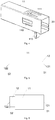
- An embodiment of the present invention provides a light homogenizing device. As shown in Fig. 1 , the light homogenizing device includes a shell 11 and a light stick 12.
- the shell 11 forms a holding chamber having openings at both ends thereof.
- the light stick 12 is located within the holding chamber, and an incident end and an emergent end of the light stick 12 correspond to the openings at both ends of the holding chamber, respectively.
- An elastic component 111 is provided on at least one surface of the shell 11. A first end of the elastic component 111 is connected to the shell 11, while a second end thereof extends into the interior of the holding chamber and presses against the light stick 12.
- the first end of the elastic component 111 is connected to the shell 11 in the embodiment may specifically means that the first end of the elastic component 111 is fixedly connected to the shell 11, or means that the first end of the elastic component 111 is in contact with the shell 11 but not fixedly connected to the shell 11.
- the second end of the elastic component 111 presses against the light stick 12 in the embodiment merely means that the second end of the elastic component 111 is in contact with the light stick 12, that is, the second end of the elastic component 111 is not fixedly connected to the light stick 12.
- the elastic component 111 in the embodiment may be specifically an elastic sheet, a spring or the like.
- the shell 11 in the embodiment of the present invention may be an integrated metal shell.
- the shell is made of copper, aluminum, alloy or other metals by a casting process.
- the shell 11 in the embodiment of the present invention may also be an integrated nonmetal shell.
- the shell is made of plastics, ceramic, rubber, resin or other nonmetals by an injection-molding process or other processes.
- the shell may also be made of a sheet.
- the sheet is a sheet metal, and the shell in the embodiment of the present invention is manufactured by a sheet metal process.
- the manufacturing process is specifically as follows: first, a rectangular sheet adapted to the size of the shell is obtained by a shearing process; then, the redundant sheet is removed by a punching process at a position where an elastic sheet is to be formed; subsequently, the reserved sheet for forming the elastic sheet is stamped to form an elastic component; and finally, the sheet is bent to form the shell in the embodiment of the present invention.
- manufacturing the shell from a sheet in the embodiment of the present invention has a simple process flow. Therefore, the shell in a preferred embodiment of the present invention is manufactured by a sheet.
- the shell 11 is manufactured by one or more sheets, the shell has joints for the sheets. Specifically, as shown in Fig. 2 , the shell 11 is manufactured by at least one sheet, and the sheet is lap-joined and fixed at a joint 20.
- Fig. 2 description is given by taking the shell manufactured by one sheet as an example. Accordingly, there is only one joint 20 on the shell 11. If the shell 11 is formed by splicing more than two sheets, there are more than two joints 20 on the shell 11.
- the sheets may be fixed at the joints 20 by adhering, welding, riveting or in other ways.
- the sheets are fixed by a spot-welding process. For example, edges on two ends of the sheets and the middle positions of the joints are spot-welded for three times by spot-welding.
- the elastic component 111 being an elastic sheet and the elastic sheet being merely provided on the top surface of the shell 11 as an example, but the embodiments of the present invention are not limited thereto.
- the shell 11 provided in an embodiment of the present invention includes only one elastic sheet, the elastic sheet may be located on any one of the top surface, bottom surface, left surface and right surface of the shell 11.
- the number of elastic sheets is not limited in the embodiments of the present invention.
- the shell 11 may also include any number of elastic sheets, for example, four elastic sheets which may be located on the top surface, bottom surface, left surface and right surface of the shell 11, respectively.
- the fixation between the shell 11 and the light stick 12 is more stable, but the manufacturing difficulty will increase with the increase of the number of the elastic sheets. Therefore, in practices, an appropriate number of elastic sheets may be provided according to the actual requirements.
- the light stick in the embodiment may be solid or hollow (in Fig. 1 , taking the light stick being hollow as an example).
- the light stick may be formed by cutting a transparent material (for example, glass, optical plastics, transparent inorganic ceramic or the like) according to a preset shape of the light stick; however, when the light stick is hollow, the shape of each surface of the light stick may be formed by cutting a reflective material (for example, a reflector, a reflecting mirror or the like), and then the surfaces formed by cutting are enclosed to form the light stick.
- a transparent material for example, glass, optical plastics, transparent inorganic ceramic or the like
- the shape of each surface of the light stick may be formed by cutting a reflective material (for example, a reflector, a reflecting mirror or the like), and then the surfaces formed by cutting are enclosed to form the light stick.
- the specific structure of the light stick is not limited.
- the light homogenizing device provided in the embodiment of the present invention includes a shell and a light stick, wherein the shell forms a holding chamber having openings at both ends thereof; the light stick is located within the holding chamber, and the openings at both ends of the holding chamber correspond to an incident end and an emergent end of the light stick, respectively; and, an elastic component is provided on at least one surface of the shell, with a first end of the elastic component being connected to the shell while a second end thereof extending into the interior of the holding chamber and pressing against the light stick. Since the incident end and the emergent end of the light stick correspond to the openings at both ends of the holding chamber formed by the shell, the incident end and the emergent end of the light stick may be prevented from being shielded.
- the elastic component may realize the fixation of the light stick, so that the light homogenizing device can operate normally. Furthermore, since the light stick is located inside the shell, an external force may act on the shell first when the external force is applied to the light homogenizing device, so that the fragile light stick is prevented from being damaged. Consequently, in this embodiment of the present invention, the light homogenizing device may be prevented from being damaged when pressed by an external force.
- an embodiment of the present invention further provides another light homogenizing device.
- a difference between the light homogenizing device provided in this embodiment and that provided in the above embodiment lies in that the shell 11 is adhered to the light stick 12.
- the volume of the holding chamber formed by the shell 11 is generally greater than the size of the light stick 12.
- the light stick 12 may be fixed by the elastic component 111, the light stick 12 might shake within the holding chamber formed by the shell 11, thereby influencing the utilization of light by the light homogenizing device. Therefore, it is also possible to further adhere the shell 11 to the light stick 12, so that the fixation of the light stick is more reliable.
- a window 112 is provided on at least one surface of the shell 11.
- the window 112 is configured to inject an adhesive between a side wall of the light stick 112 and an inner wall of the shell 11.
- the adhesive may be specifically photosensitive adhesive, glue, resin or the like.
- the window 112 may be configured to not only inject the photosensitive adhesive but also cure the injected photosensitive adhesive.
- the specific position and the number of the window 112 are not limited as long as the adhesive can be injected between the side wall of the light stick 12 and the inner wall of the shell 11.
- the photosensitive adhesive is injected between the side wall of the light stick 12 and the inner wall of the shell 11 through the window 112, so that a gap between the side wall of the light stick 21 and the inner wall of the shell 11 is filled by the photosensitive adhesive; and then, the photosensitive adhesive is cured by light irradiation at the window 212, at the openings at both ends of the shell 11, or at other positions.
- the difficulty of the process of adhering the shell 11 to the light stick 12 may be reduced, and the adhesive may be prevented from polluting the incident end and the emergent end of the light stick 12.
- an embodiment of the present invention further provides another light homogenizing device.
- another light homogenizing device Specifically, as shown in Fig. 4 , at least one protrusion 113 is provided on an outer surface of the shell 11. The protrusion 113 is configured to position the light homogenizing device when mounting the light homogenizing device.
- the position of the light homogenizing device as an optical component in a light path is preset. Therefore, after the light stick 12 is placed within the shell 11 to form the light homogenizing device, it is required to place the light homogenizing device at the preset position in the light path.
- the light homogenizing device may be positioned according to the position of the protrusion 13 in the mounting process of the light homogenizing device, so that the light homogenizing device is accurately placed at the preset position in the light path.
- protrusion 113 being provided on the outer bottom surface of the shell, but the embodiments of the present invention are not limited thereto. In the embodiments of the present invention, the protrusion 113 may also be provided at other positions of the shell 11. In addition, in the embodiments of the present invention, it is also possible to provide a plurality of (for example, two) protrusions 113 on the shell 11. By providing a plurality of protrusions 113, the positioning of the light homogenizing device in the mounting process is more accurate.
- an embodiment of the present invention further provides another light homogenizing device. Specifically, as shown in Fig. 5 , a distance between the end faces 51, 52 at both ends of the shell 11 is smaller than a distance between the incident end 121 and the emergent end 122 of the light stick 12.
- the light homogenizing device In the mounting process of the light homogenizing device, the light homogenizing device is positioned by reference to a certain component on the supporting pedestal. Therefore, the position of the light stick of the light homogenizing device can be ensured to be accurate only when the light homogenizing device is fitted to this component.
- the shell 11 is generally a sheet metal machined part, and the machining tolerance of the sheet metal machined part is generally greater than that of an optical device (i.e. the light stick). If the shell 11 and the light stick 12 are manufactured in a same size, the distance between the openings at both ends of the shell 11 may be greater than the distance between the incident end 121 and the emergent end 122 of the light stick 12.
- the shell 11 will influence the positioning of the light homogenizing device, so as to influence the positioning of the light stick 12. Therefore, optionally, the distance between the openings at both ends of the shell 11 should be smaller than the distance between the incident end 121 and the emergent end 122 of the light stick, in order to avoid the influence on the positioning of the light stick.
- an end face 51 of the opening at the first end of the shell 11 is aligned to the incident end 121 of the light stick 12, and an end face 52 of the opening at the second end of the shell 11 is located between a surface of the incident end 121 and a surface of the emergent end 122 of the light stick 12.
- the end face 52 of the opening at the second end of the shell 11 is aligned to emergent end 122 of the light stick 12, and the end face 51 of the opening at the first end of the shell 11 is located between a surface of the incident end 121 and a surface of the emergent end 122 of the light stick 12.
- the shell in the light homogenizing device provided in the above embodiment may prevent the light stick from being damaged by an external force in the mounting and adjustment process. Therefore, an adjustment structure for adjusting the position of the light stick may be further provided on the basis of the above embodiment. Therefore, optionally, the light homogenizing device provided in this embodiment of the present invention further includes an adjustment structure for adjusting the position of the shell. Since the shell and the light stick within the holding chamber formed by the shell are fixed relative to each other, when the light homogenizing device is adjusted, first, the position of the shell is adjusted by the adjustment structure, and then the light stick is driven to move by the shell.
- an embodiment of the present invention further provides an adjustment structure.
- the adjustment structure 80 forms an accommodating chamber having openings at both ends thereof.
- the shell 11 is located within the accommodating chamber, and the openings at both ends of the accommodating chamber correspond to the openings at both ends of the holding chamber formed by the shell 11, respectively.
- an incident end 121 and an emergent end 122 of the light stick 12 within the shell 11 correspond to the openings at both ends of the accommodating chamber, respectively.
- Adjustment holes 81 and adjustment protrusions 82 adapted to the adjustment holes 81 are formed on at least one surface of the adjustment structure 80, and the adjustment protrusions 82 pass through the adjustment holes 81 and press against the shell 11.
- Elastic support components 83 are provided on a surface opposite to the surface on which the adjustment holes 81 are formed. A first end of each of the elastic support components 83 is connected to the adjustment structure 80, while a second end thereof extends into the interior of the accommodating chamber and presses against the shell 11.
- the first end of each of the elastic support components 83 is connected to the adjustment structure 80 in this embodiment may specifically means that the first end of each of the elastic support components 83 is fixedly connected to the adjustment structure 80, or means that the first end of each of the elastic support components 83 is in contact with the adjustment structure 80 but not fixedly connected to the adjustment structure 80.
- the second end of each of the elastic support components 83 presses against the shell 11 in this embodiment merely means that the second end of each of the elastic support components 83 is in contact with the shell 11, that is, the second end of each of the elastic support components 83 is not fixedly connected to the shell 11.
- the adjustment holes 81 may be specifically threaded holes, unthreaded holes or the like
- the adjustment protrusions 82 may be specifically screws, bolts or the like
- the elastic support components 83 may be specifically elastic sheets, springs or the like.
- the adjustment structure in this embodiment of the present invention may be formed by enclosing a plurality of independent cover plates, for example, four independent cover plates, wherein adjustment holes 81 and adjustment protrusions 82 adapted to the adjustment holes 81 are formed on two of the cover plates, elastic support components 83 are formed on the other two of the cover plates, and the four independent cover plates are connected and fixed together by adhering, welding, fixing by adjustment screws or in other ways to form an accommodating chamber with openings at both ends thereof.
- the adjustment structure in this embodiment of the present invention may also be formed integrally.
- the differences between the integrated adjustment structure and the adjustment structure including a plurality of independent cover plates lie in that: for the adjustment structure including a plurality of independent cover plates, the light stick may be first placed within the accommodating chamber formed by the plurality of cover plates and then fixed, or, the plurality of cover plates may be fixed to form the accommodating chamber first and then the light stick is put into the accommodating chamber from an opening at one end where an included angle between the elastic support component and the accommodating chamber is an obtuse angle; in contrast, for the integrated adjustment structure, the light stick may be placed within the accommodating chamber formed by the adjustment chamber only in the latter way.
- the screw on the top of the adjustment structure may be rotated clockwise to push the screw toward the accommodating chamber so as to press against the shell 11, then the shell 12 presses against the elastic sheet on the bottom of the adjustment structure 80 to allow the elastic sheet to be deformed, and the shell 11 drives the light stick 12 therein to move downward; and, when the light stick 12 needs to be adjusted upward, the screw on the top of the adjustment structure 80 may be rotated counterclockwise to reduce the length of the screw extending into the accommodating chamber, and the shell 11 is moved upward under the action of the upward elastic force of the elastic sheet on the bottom of the adjustment structure 80 so as to drive the light stick 12 to move upward.
- the screw on the left side of the adjustment structure may be rotated clockwise; and, when the light stick 12 needs to be adjusted leftward, the screw on the left side of the adjustment structure 80 may be rotated counterclockwise.
- the light homogenizing device may realize the adjustment of the light stick in one direction; and, if adjustment holes and adjustment protrusions are formed on a plurality of surfaces of the adjustment structures, and elastic sheets are provided on surfaces opposite to these surfaces on which the adjustment holes are formed, the adjustment of the light stick in multiple directions may be realized.
- adjustment holes and adjustment protrusions are formed on two vertical surfaces of the adjustment structure, and elastic support components are provided on surfaces opposite to the surfaces on which the adjustment holes are formed, so that the adjustment of the light stick in the upper, lower, left and right directions may be realized by the two groups of the adjustment holes, the adjustment protrusions and the elastic support components.
- the adjustment holes and the adjustment protrusions are formed on two vertical surfaces of the adjustment structure and providing the elastic support components on surfaces opposite to the surfaces on which the adjustment holes are formed, the adjustment of the light stick in any direction other than the axial direction may be realized. Therefore, such a design may simplify the structure of the light homogenizing device, and thus simplify the process flow of manufacturing the light homogenizing device.
- the adjustment structure may also reduce the movement step length of the adjustment protrusions during adjustment and thus improve the accuracy of adjustment.
- the adjustment structure provided in this embodiment of the present invention forms an accommodating chamber having openings at both ends thereof; the shell is located within the accommodating chamber, and the openings at both ends of the accommodating chamber correspond to an incident end and an emergent end of the light stick, respectively; adjustment holes and adjustment protrusions adapted to the adjustment holes are formed on at least one surface of the adjustment structure, and the adjustment protrusions may pass through the adjustment holes and presses against the shell within the accommodating chamber; and, elastic support components are provided on a surface opposite to the surface on which the adjustment holes are formed, with a first end of each of the elastic support components being connected to the adjustment structure while a second end thereof extending into the interior of the accommodating chamber and pressing against the shell.
- the elastic support components may be allowed to be pushed toward the accommodating chamber so as to press against the shell within the accommodating chamber, so that the shell is moved in a direction away from the surface on which the adjustment holes are formed; similarly, by rotating the elastic support components in a reverse direction, the length of the elastic support components extending into the accommodating chamber is reduced, so that the elastic support components on a surface opposite to the surface on which the adjustment holes are formed make the light stick close to the surface on which the adjustment holes are formed. Consequently, the light homogenizing device provided in this embodiment of the present invention may realize the adjustment of the position of the light stick.
- both the acting force generated by the elastic support components and the acting force generated by the adjustment protrusions act on the shell during the adjustment process, and the light stick is driven to move by the shell, so that the shell may prevent an external force from directly acting on the light stick. Therefore, in this embodiment of the present invention, the shell may also prevent the light stick from being damaged by an external force during the adjustment process.
- the light homogenizing device provided in this embodiment may realize the adjustment of the position of the light stick, more incident light may be received by adjusting the incident end of the light stick, and/or the emergent light is projected to a designed position by adjusting the emergent end of the light stick. As can be seen, this embodiment of the present invention may also improve the utilization of light.
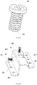
- An embodiment of the present invention further provides an improved structure of adjustment protrusions. Specifically, as shown in Fig. 9 , an end 90 of each of the adjustment protrusions 82 contacting with the shell 11 is hemispherical.
- each of the adjustment protrusions 82 which is in contact with the shell 11 being hemispherical, the contact of the shell with the adjustment protrusions 82 may be point contact. Consequently, the friction generated when rotating the adjustment screws may be reduced during the adjustment process, the adjustment becomes smoother, and the adjustment distance may be controlled more accurately.
- an anaerobic adhesive is coated on the surfaces of the adjustment protrusions 82.
- the anaerobic adhesive is a special engineering resin coated on screws, bolts or other structures, and is highly stable and resistant to acids, alkalis and other solvents.
- the adjustment structure 80 includes a first adjustment support 801 and a second adjustment support 802.
- Fig. 10 is a schematic structure diagram of the first adjustment support 801
- Fig. 11 is a schematic structure diagram of the second adjustment support 802.
- the first adjustment support 801 includes a first wallboard and a second wall board
- the second adjustment support 802 includes a third wallboard and a fourth wallboard.
- the first wallboard, the second wallboard, the third wallboard and the fourth wallboard are enclosed to form the accommodating chamber.
- Adjustment holes 81 and adjustment protrusions 82 adapted to the adjustment holes 81 are formed on both the first wallboard and the second wallboard, and elastic support components 83 are provided on the third wallboard and the fourth wallboard respectively.
- the adjustment structure 80 is formed by the first adjustment support 801 and the second adjustment support 802, the adjustment holes 81 and the adjustment protrusions 82 are formed on the first adjustment support, and the elastic support components 83 are formed on the second adjustment support. Therefore, it is possible to manufacture two adjustment holes 81 on an alloy sheet and then bend the alloy sheet to form the first adjustment support; similarly, it is possible to manufacture two elastic support components 83 on another alloy sheet and then bend the alloy sheet to form the second adjustment support, so that the adjustment structure is formed by enclosing the first adjustment support 801 and the second adjustment support 802. Accordingly, the manufacture process of the adjustment structure may be simplified, and it is suitable for batch production.
- the first adjustment support 801 and the second adjustment support 802 may be fixed by adhering, welding, fixing with screws or in other ways.
- bent portions 84 are formed on a left edge and a right edge of the first adjustment support 801, and through holes 841 are formed on the bent portions 84.
- bent portions 85 are formed on a left edge and a right edge of the second adjustment support 802, and through holes 851 are formed on the bent portions 85. Screws, bolts, pins or other fixing components are allowed to pass through the through holes formed on the bent portions of both the first adjustment support and the second adjustment support, and the first adjustment support 801 and the second adjustment support 802 are fixed by the fixing components. Fixing the first adjustment support 801 and the second adjustment support 802 by fixing components is advantageous for the disassembly and maintenance of the adjustment structure in the later stage.
- the light homogenizing device further includes a press-fitting component 86 connected to the first adjustment support 801; and a press 861 is provided on the press-fitting component 86, and a first end of the press 861 is fixed to the press-fitting component 86 while a second end thereof extends into the interior of the accommodating chamber and presses against the shell 11.
- the fixation of the light homogenizing device becomes firmer, and the pressure in each direction may be received by the light stick, so that the light stick is fixed at a preset position inside the accommodating chamber.
- the first adjustment support 801 and the press-fitting component 86 are formed integrally.
- the manufacture process of the light homogenizing device may be simplified.
- through holes 130 are formed on the press-fitting component 86 at positions corresponding to that on the first adjustment support 80, and the first adjustment support 801 and the press-fitting component 86 are fixed by screws.
- the first adjustment support 801 and the press-fitting component 86 are independent of each other and fixed by screws.
- the shell provided with the light stick may be first placed within the accommodating chamber formed by the adjustment structure, and the press-fitting component is then mounted, so that the mounting becomes simple.
- Fig. 14 is a schematic structure diagram after the first adjustment support 801, the second adjustment support 802, the press-fitting component, the shell 11 and the light stick 12 in the embodiment have been mounted.
- the light homogenizing device may allow the light stick 12 to be finely adjusted in each direction in order to enable the incident end of the light stick to receive more incident light and/or enable the emergent end of the light stick to project the emergent light onto a designed position.
- this embodiment of the present invention may adjust the light homogenizing device and thus improve the utilization of light.
- an embodiment not part of the present invention further provides another light homogenizing device.
- the light homogenizing device further includes a pedestal 15, a support 16, a locking component 17 and an elastic support component 18.
- Fig. 15 is a structure diagram of the light stick 12, the shell 11, the locking component 17 and the elastic support component 18 in the light homogenizing device
- Fig. 16 is a structure diagram of the pedestal 15, the support 16, the locking component 17 and the elastic support component 18 in the light homogenizing device
- Fig. 17 is an overall schematic structure diagram of the assembled light homogenizing device.
- the pedestal 15 includes a bottom plate 151, a first side plate 152 vertically connected to the bottom plate 151, and a second side plate 153 vertically connected to the bottom plate 151 and adjacent to the first side plate 152.
- a groove 1531 for exposing the first end of the shell 11 is provided on the second side plate 153.
- the first end of the shell 11 is fixed within the groove 1531.
- the second side plate 153 and the first side plate 152 may be connected fixedly to each other, or may be independent of each other. By fixedly connecting the second side plate 153 to the first side plate 152, the pedestal 15 may become more stable. Therefore, preferably, the second side plate 153 is fixedly connected to the first side plate 152.
- the support 16 is fixed to the pedestal 15, the locking component 17 is located on the support 16, and the elastic support component 18 is located on a surface of the pedestal 15 opposite to the locking component 17. Both the locking component 17 and the elastic support component 18 press against the surface of the shell 11 for fixing the position of the shell 11.
- all the pedestal, the support and the shell in this embodiment may be made of iron, copper, aluminum, alloy or other metals, or may be made of ceramic, plastics or other nonmetals. In comparison with the nonmetals, the metals have better heat conductivity, ductility and strength. Therefore, the pedestal, the support and the shell in this embodiment of the present invention are preferably made of metals.
- the pedestal 15 and the support 16 are formed integrally in this embodiment. Specifically, the pedestal 15 and the support 16 may be formed integrally by a casting process.
- the light homogenizing device includes a light stick, a shell, a pedestal, a support, a locking component and an elastic support component
- the pedestal is composed of a bottom plate, a first side plate and a second side plate, and a groove for exposing the first end of the shell is provided on the second side plate.
- the support is fixed to the pedestal, the locking component on the support and the elastic support component located on a surface of the pedestal opposite to the locking component press against the surface of the shell and may fix the position of the shell, so that the shell may be further prevented from shaking by the locking component and the elastic support component.
- the light homogenizing device provided in this embodiment of the present invention may accurately position the first end of the shell and may prevent the shell from shaking as a whole, the shell may be accurately positioned. Moreover, since the light stick is located within the holding chamber formed by the shell, the accurate positioning of the light stick may be realized in this embodiment of the present invention.
- an embodiment of the present invention further provides a specific structure of the locking component 17.
- the locking component 17 includes an adjustment hole 171 formed on the support 16 and an adjustment protrusion 172 adapted to the adjustment hole 171.
- the adjustment hole 171 may be a threaded hole, an unthreaded hole or the like, and the adjustment protrusion 172 may be a screw, a bolt or the like adapted to the adjustment hole 171.
- the elastic support component 18 may be a spring, an elastic sheet or the like, and the axis of the spring is vertical to a contact surface of the spring with the pedestal 15 when the elastic support component 18 is a spring.
- the elastic support component 18 is a spring, and the cross-sectional area of one end of the spring 18 in contact with the shell 11 is smaller than that of one end of the spring 18 in contact with the pedestal 15.
- the spring 18 By designing the spring 18 as a conical spring and making the cross-sectional area of one end of the spring 18 in contact with the shell 11 smaller than that of one end of the spring in contact with the pedestal 15, the contact surface of the shell 11 with the spring 18 may be reduced, and the adjustment distance may be accurately controlled. In addition, the contact area of the spring 18 with the pedestal 15 may also be increased, so that the spring 18 may be prevented from shifting due to an external force.
- the position of the shell 12 may be fixed, and the position of the light stick 12 may also be adjusted.
- the process of adjusting the position of the light stick 12 may be as follows: when the light stick 12 needs to be adjusted in a direction close to the bottom plate 151, the adjustment protrusion 172 may be pushed toward the direction close to the bottom plate 151 by rotating clockwise the adjustment protrusion 172; the shell 11 is pressed by the adjustment protrusion 172 and then presses the elastic support component 18 between the shell 12 and the bottom plate; and, the elastic support component 18 is compressed, and the shell 11 is moved in the direction close to the bottom plate 151, so that the light stick 12 within the shell 11 is driven to move in the direction close to the bottom plate 151.
- a contact point of the elastic support component 18 with the shell 11 may be allowed to leave gradually away from the bottom plate 151 by rotating counterclockwise the elastic support component 18 opposite to the bottom plate 151, and the stress generated by the elastic support component 18 between the shell 11 and the bottom plate 151 allows the shell 11 to move in the direction away from the bottom plate 151, so that the light stick 12 within the shell 11 is driven to move in the direction away from the bottom plate 151.
- the light homogenizing device may realize the adjustment of the light stick in one direction; and, if adjustment holes 171, adjustment protrusions 172 and elastic support components 18 are formed in multiple directions, the adjustment of the light stick in multiple directions may be realized. Therefore, it is preferably to form adjustment holes 171, adjustment protrusions 172 and elastic support components 18 in multiple directions. By forming adjustment holes 171, adjustment protrusions 172 and elastic support components 18 in multiple directions, the movement of the light stick in a plane of the cross-section in any direction may be realized. In other words, based on the direction shown in Fig. 18 , the upper, lower, left and right adjustment of the light stick may be realized.
- the support 16 includes a horizontal rib 161 parallel to the bottom plate 151 and a vertical rib 162 parallel to the first side plate 152, and the locking component 17 is provided on both the horizontal rib 161 and the vertical rib 162.
- adjustment holes 171, adjustment protrusions 172 and elastic support components 18 are formed on two vertical surfaces, the adjustment of the light stick 12 in the plane of the cross-section in any direction may be realized. Therefore, such a design may reduce the number of the adjustment holes 171, the adjustment protrusions 172 and the elastic support components 18 on the light homogenizing device, simplify the structure of the light homogenizing device, and thus simplify the manufacture process of the light homogenizing device.
- an embodiment of the present invention further provides a specific implementation of fixing the first end of the shell 11 within the groove 1531.
- a claw 190 is provided at the first end of the shell 11, and a first through hole 191 is provided on the claw 190; a second through 192 is provided on the second side plate 153 at a position corresponding to the first through hole 191; and, a fixing element passes through the first through hole 191 and the second through hole 192 to fix the first end of the shell within the groove.
- the fixing element may be specifically a screw, a bolt, a pin or the like.
- the direction of an acting force generated by the adjustment protrusion 172 and the direction of an acting force generated by the elastic support component 18 may not be on a straight line; and, if the direction of an acting force generated by the adjustment protrusion 172 and the direction of an acting force generated by the elastic support component 18 is not on a straight line, a torque will be generated, so that the shell 11 will drive the light stick 12 to rotate. Therefore, as shown in Fig. 15 , two claws 190 are provided at the first end of the shell, and the two claws 190 are corresponding to two sides of the groove 1531, respectively. By providing two claws 190 at the first end of the shell 11 and making the two claws 190 correspond to two sides of the groove 1531, respectively, the light stick may be prevented from rotating in the above case.
- an embodiment of the present invention further provides another improved structure of the shell 11.
- a positioning hole 193 is further formed on the claw 190, and a positioning column 194 is provided on the second side plate 153 at a position corresponding to the positioning hole 193.
- the shell 11 may be accurately placed at the preset position when in mounting, and the accurate positioning may be realized when the shell 11 and the second side plate 153 are fixed.
- a spacer is further provided between the claw 190 and the second side plate 153.
- the position of the light stick may be adjusted only in the plane of the cross-section of the light stick but cannot be adjusted in a direction vertical to the cross-section of the light stick; while in this embodiment of the present invention, by additionally providing a spacer between the claw 190 and the second side plate 153, the position of the light stick may be further adjusted in a direction vertical to the cross-section of the light stick by adjusting the thickness of the spacer.
- the adjustment of the light stick in the upper, lower, left, right, front and rear directions may be realized.
- Still another embodiment of the present invention provides a laser projection apparatus.
- the laser projection apparatus includes the light homogenizing devices provided in any one of the above embodiments.
- the laser projection apparatus may be a laser TV set, a projector or the like.
- the laser projection apparatus may include a laser light source 21, a light engine 22, a lens 23 and a slide screen 24.
- the laser light source 21 may include a laser device 211, a fluorescent wheel 212, a color filter wheel 213 or other components.
- the laser device 211 may be a monochromatic laser device, or may be a bichromatic laser device. At least one kind of fluorescent powder is provided on the fluorescent wheel 212, and laser light emitted by the laser device 211 can be mixed with exciting light generated by the fluorescent wheel to form white light.
- the color filter wheel 213 filters the mixed light in order to improve the purity of fluorescence.
- the light engine 22 includes a light homogenizing device 221, a light path device 222, a Digital Micro mirror Device (DMD) chip 223 or other components.
- the light homogenizing device is the light homogenizing device provided in any one of the above embodiments.
- Light beams sequentially output by the color filter wheel 213 enter the light homogenizing device 221 for homogenizing and/or for changing the divergent angle, so that the light beams meet the requirements of the DMD on the beam energy distribution and the incident angle.
- light is transmitted to the DMD chip by the light path device 222, and the DMD chip receives light of three primary colors and is rotated within a certain range under the driving of the current so as to adjust the amount of light entering the lens 23, so that different colors are presented on the lens.
- the lens 23 receives the light modulated by the DMD, and the light is eventually transmitted to the projection screen 24 by refraction, reflection or other processes by a plurality of optical lenses so as to form a projected image.
Landscapes
- Physics & Mathematics (AREA)
- General Physics & Mathematics (AREA)
- Optics & Photonics (AREA)
- Projection Apparatus (AREA)
- Non-Portable Lighting Devices Or Systems Thereof (AREA)
Description
- The present disclosure relates to the technical field of lasers, and in particular to a light homogenizing device and a laser projection apparatus.
- Due to its advantages of excellent monochromaticity, high directivity, high luminous flux and the like, at present, the laser light as excellent coherent light has been widely applied in various fields, such as industry, healthcare, science & research, information and military. In the display field, it is more and more common to use the laser light as a light source.
- Since the laser light is a high-energy light beam, small light spots are formed generally by beam shaping during the transmission thereof in a light path, so that the energy density of the laser becomes higher. If the energy density of the light spots is not uniform, it is likely to cause burns due to a too large local impact onto an optical lens, and meanwhile, non-uniform image brightness is caused after the light spots enter a lighting system of a light engine and are then projected. Therefore, it is expected that the utilized laser beam is a homogenized light beam. In the applications of the laser light, a light homogenizing component is a very important element, for example, a light stick, a diffuser film, a fly's-eye lens or the like. Wherein, the light stick is common, and is generally located at an output end of a light source and an input end of the lighting system of the light engine. The light stick can reflect light entering the interior of the light stick for multiple times so as to homogenize the light beam. Meanwhile, in accordance with the principle of constant etendue, the divergent angle of light can also be changed by adjusting the area of the incident end and the area of the emergent end of the light stick. However, since the light stick is generally made of glass and thus fragile, the light stick needs to be protected against breaking.
-
US2009/015802A1 is embodied in an adjusting mechanism for a rod module adapted to an optical engine. The adjusting mechanism utilizes two wedge-shaped blocks moving in perpendicular directions so as to convert the vertical adjustment of horizontal adjusting component into horizontal adjustment of an LIR module. Therefore, operators may adjust the horizontal and vertical position of the rod module from the same side of the projector, thus increasing the convenience in adjusting the position of the rod module. -
US6394611B1 discloses a solid rod dust-proof structure for projecting apparatuses. The solid rod includes an incident-beam surface and an outgoing-beam surface. The dust-proof structure includes: a housing provided with a first chamber and a second chamber connecting each other wherein the cross section of the second chamber is greater than that of the first chamber. The first chamber contains the solid rod, and a stopping portion is installed on the opposite end of the second chamber for stopping the solid rod; and a dust-proof plate being a transparent plate is contained in the second chamber to completely cover the outgoing-beam surface of the solid rod. Using the above structure, the outgoing-beam surface of the solid rod can be completely covered by the transparent dust-proof plate so that the structure is free from dust and the light transmitting through the outgoing-beam surface will not be blocked. -
US2006/227304A1 discloses an optical assembly for a projection system includes a light tunnel, a light tunnel holder that supports the light tunnel, an exterior casing that supports the light tunnel holder, a resilient member disposed between the light tunnel holder and the exterior casing to resiliently support the light tunnel holder, and an aligning unit that is disposed opposite the resilient member to align the light tunnel. The aligning unit can have at least one holder protrusion formed on an outer surface of the light tunnel holder, and a movable member that has a pressing protrusion for contact with the holder protrusion. The movable member slides on the outside of the light tunnel holder. -
CN101900925B provides an optical machine module and a projection device. The optical machine module comprises a casing, a screw and a light guide device, wherein the casing is provided with a screw hole; the screw is rotatably locked and attached to the screw hole along the first direction and is provided with an end part. The light guide device is provided with an inclined plane and is abutted against the end part of the screw towards the second direction, wherein the second direction is vertical to the first direction. When the screw rotates along the first direction, the inclined plane of the light guide device is pushed by the end part of the screw to move towards the opposite direction of the second direction.; The space of the optical machine module, which is positioned in the second direction of the light guide device, can be made away so as to increase the design elasticity of the space inside the projection device. -
CN101354463A provides an integral column adjustable device; the integral column adjustable device and an integral column are commonly arranged on a light engine shell which leads the integral column to carry out the position adjustment in the first direction and the second direction; the adjustable device comprises two elastic parts which respectively provide elastic recovery forces opposite to the first direction and the second direction, two top-pushing parts which are respectively arranged at the opposite sides of the integral columns corresponding to the elastic parts; the two top-pushing parts are respectively provided with a contact surface; two top-pushing parts can move along the same operation direction and respectively apply the positive forces which can lead the integral column to move in the first direction and the second direction;; the two top-pushing parts which can move in the same operation direction are matched with the two elastic parts so as to lead the integral column to move respectively in the first direction and the second direction, thus achieving the object that the two-dimensional position of the integral column can be adjusted by the same operation direction. - In the first aspect, an embodiment of the present invention provides a light homogenizing device, as defined in independent claim 1, including a shell and a light stick; wherein, the shell forms a holding chamber having openings at both ends thereof; the light stick is located within the holding chamber, and an incident end and an emergent end of the light stick correspond to the openings at both ends of the holding chamber, respectively; and, an elastic component is provided on at least one surface of the shell, with a first end of the elastic component being connected to the shell while a second end thereof extending into the interior of the holding chamber and pressing against the light stick.
- In an embodiment of the first aspect, the shell is made of at least one sheet, and the sheet is lap-jointed and fixed at a joint.
- Preferably, the shell is adhered to the light stick.
- Optionally, a window is provided on at least one surface of the shell and used for injecting an adhesive between a side wall of the light stick and an inner wall of the shell.
- Preferably, a distance between the openings at both ends of the shell is smaller than a distance between the incident end and the emergent end of the light stick.
- Optionally, at least one protrusion for positioning the light homogenizing device when mounting the light homogenizing device is provided on an outer surface of the shell.
- In the first aspect, the light homogenizing device further comprises an adjustment structure; and the adjustment structure is configured to adjust the position of the shell.
- Specifically, the adjustment structure forms an accommodating chamber having openings at both ends thereof; the shell is located within the accommodating chamber, and an incident end and an emergent end of the light stick correspond to the openings at both ends of the accommodating chamber; adjustment holes and adjustment protrusions adapted to the adjustment holes are formed on at least one surface of the adjustment structure, and the adjustment protrusions pass through the adjustment holes and press against the shell; and, elastic support components are provided on a surface opposite to the surface on which the adjustment holes are formed, with a first end of each of the elastic support components being connected to the adjustment structure while a second end thereof extending into the interior of the accommodating chamber and pressing against the shell.
- Preferably, an end of the adjustment protrusion pressing against the shell is hemispherical.
- Specifically, the adjustment structure comprises a first adjustment support and a second adjustment support; the first adjustment support comprises a first wallboard and a second wallboard, and the second adjustment support comprises a third wallboard and a fourth wallboard; the first wallboard, the second wallboard, the third wallboard and the fourth wallboard are enclosed to form the accommodating chamber; and, adjustment holes and adjustment protrusions adapted to the adjustment holes are formed on both the first wallboard and the second wallboard, and elastic support components are provided on the third wallboard and the fourth wallboard respectively.
- Further, the light homogenizing device may further comprises a press-fitting component connected to the first adjustment support; and a press is provided on the press-fitting component, with a first end of the press being fixed to the press-fitting component while a second end thereof extending into the interior of the accommodating chamber and pressing against the shell.
- In further embodiment of the first aspect, the light homogenizing device further comprises a pedestal, a support, a locking component and an elastic support component; the pedestal comprises a bottom plate, a first side plate vertically connected to the bottom plate, and a second side plate vertically connected to the bottom plate and adjacent to the first side plate, with a groove for exposing the first end of the shell being provided on the second side plate; the first end of the shell is fixed within the groove; the support is fixed to the pedestal, the locking component is located on the support, and the elastic support component is located on a surface of the pedestal opposite to the locking component; and, both the locking component and the elastic support component press against the surface of the shell for fixing the position of the shell.
- Optionally, the locking component comprises: an adjustment hole formed on the support and an adjustment protrusion adapted to the adjustment hole.
- Optionally, the support comprises a horizontal rib parallel to the bottom plate and a vertical rib parallel to the first side plate, and the locking component is provided on both the horizontal rib and the vertical rib.
- Further, a claw is provided at the first end of the shell, and a first through hole is provided on the claw; a second through hole is provided on the second side plate at a position corresponding to the first through hole; and, a fixing element passes through the first through hole and the second through hole to fix the first end of the shell within the groove.
- Furthermore, a spacer is further provided between the claw and the second side plate.
- Preferably, the elastic support component is a spring, and the cross-sectional area of one end of the spring in contact with the shell is smaller than that of one end of the spring in contact with the pedestal.
- In the second aspect, a laser projection apparatus, as defined in independent claim 9, is provided, including: a laser light source, a light engine and a lens, which are arranged successively, wherein the light engine includes a light homogenizing device which may be any one of the light homogenizing device provided in the above embodiments. Specifically, the light homogenizing device may include a shell and a light stick; the shell forms a holding chamber having openings at both ends thereof; the light stick is located within the holding chamber, and the openings at both ends of the holding chamber correspond to an incident end and an emergent end of the light stick, respectively; and, an elastic component is provided on at least one surface of the shell, with a first end of the elastic component being connected to the shell while a second end thereof extending into the interior of the holding chamber and pressing against the light stick.
- In the second aspect, the light homogenizing device further comprises an adjustment structure; the adjustment structure forms an accommodating chamber having openings at both ends thereof; the shell is located within the accommodating chamber, and an incident end and an emergent end of the light stick correspond to the openings at both ends of the accommodating chamber; adjustment holes and adjustment protrusions adapted to the adjustment holes are formed on at least one surface of the adjustment structure, and the adjustment protrusion pass through the adjustment holes and press against the shell; and, elastic support components are provided on a surface opposite to the surface on which the adjustment holes are formed, with a first end of each of the elastic support components being connected to the adjustment structure while a second end thereof extending into the interior of the accommodating chamber and pressing against the shell.
- In another embodiment, the light homogenizing device further comprises a pedestal, a support, a locking component and an elastic support component; the pedestal comprises a bottom plate, a first side plate vertically connected to the bottom plate, and a second side plate vertically connected to the bottom plate and adjacent to the first side plate, with a groove for exposing the first end of the shell being provided on the second side plate; the first end of the shell is fixed within the groove; the support is fixed to the pedestal, the locking component is located on the support, and the elastic support component is located on a surface of the pedestal opposite to the locking component; and, both the locking component and the elastic support component compress the surface of the shell for fixing the position of the shell.
- To describe the technical solutions in the embodiments of the present invention more clearly, the accompanying drawings to be used in the description of the embodiments will be briefly described below.
-
Fig. 1 is a first schematic structure diagram of a light homogenizing device according to an embodiment of the present invention; -
Fig. 2 is a first schematic structure diagram of a shell according to an embodiment of the present invention; -
Fig. 3 is a second schematic structure diagram of the shell according to an embodiment of the present invention; -
Fig. 4 is a third schematic structure diagram of the shell according to an embodiment of the present invention; -
Fig. 5 is a side view of a shell and a light stick according to an embodiment of the present invention; -
Fig. 6 is a side view of another shell and a light stick according to an embodiment of the present invention; -
Fig. 7 is a side view of still another shell and a light stick according to an embodiment of the present invention; -
Fig. 8 is a second schematic structure diagram of the light homogenizing device according to an embodiment of the present invention; -
Fig. 9 is a schematic structure diagram of an adjustment screw according to an embodiment of the present invention; -
Fig. 10 is a schematic structure diagram of a first adjustment support of the adjustment structure according to an embodiment of the present invention; -
Fig. 11 is a schematic structure diagram of a second adjustment support of the adjustment structure according to an embodiment of the present invention; -
Fig. 12 is a schematic structure diagram of a press-fitting component according to an embodiment of the present invention; -
Fig. 13 is a schematic structure diagram after the first adjustment support and the press-fitting component are mounted, according to an embodiment of the present invention; -
Fig. 14 is a third schematic structure diagram of the light homogenizing device according to an embodiment of the present invention; -
Fig. 15 is a first schematic breakdown diagram of the light homogenizing device according to an embodiment not part of the present invention; -
Fig. 16 is a second schematic breakdown diagram of the light homogenizing device according to an embodiment not part of the present invention; -
Fig. 17 is a fourth schematic structure diagram of the light homogenizing device according to an embodiment not part of the present invention; -
Fig. 18 is a fifth schematic structure diagram of the light homogenizing device according to an embodiment not part of the present invention; -
Fig. 19 is a sixth schematic structure diagram of the light homogenizing device according to an embodiment not part of the present invention; and -
Fig. 20 is a schematic structure diagram of a laser projection apparatus according to an embodiment of the present invention. -
- 11: shell; 12: light stick; 111: elastic component; 20: joint;
- 112: window; 113: protrusion;
- 51: end face of the opening at the first end of the shell;
- 52: end face of the opening at the second end of the shell;
- 121: incident end of the light stick; 122: emergent end of the light stick;
- 80: adjustment structure; 81: adjustment hole;
- 82: adjustment protrusion; 83: elastic support component;
- 90: end of the adjustment protrusion in contact with the shell;
- 801: first adjustment support; 802: second adjustment support;
- 84: bent portion of the first adjustment support;
- 85: bent portion of the second adjustment support;
- 841: through hole on the bent portion of the first adjustment support;
- 851: through hole on the bent portion of the second adjustment support;
- 86: press-fitting component; 861: press;
- 130: through hole of the first adjustment support;
- 15: pedestal; 16: support; 17: locking component;
- 18: elastic support component;
- 151: bottom plate; 152: first side plate; 153: second side plate;
- 1531: groove; 161: horizontal rib; 162: vertical rib;
- 171: adjustment hole; 172: adjustment protrusion;
- 190: claw; 191: first through hole; 192: second through hole;
- 193: positioning hole; 194: positioning column;
- 21: laser light source; 22: light engine; 23: lens; 24: slide screen;
- 211: laser device; 212: fluorescent wheel; 213: color filter wheel;
- 221: light homogenizing device; 222: light path device; and 223: DMD chip.
- It is to be noted that, the orientation or position relation indicated by terms "upper", "lower", "front", "rear", "left", "right", "top", "bottom", "inside", "outside" or the like is an orientation or position relation shown based on the accompanying drawings, merely for describing the present disclosure and simplifying the description but not for indicating or implying that the specified device or element must have a particular orientation or be constructed and operated in a particular orientation. Therefore, the terms cannot be interpreted as limiting the present disclosure.
- In addition, the phrase "A and/or B" in the embodiments of the present disclosure indicates three choices: 1) A; 2) B; and 3) both A and B. In other words, the phrase "and/or" can show the "and" relationship or the "or" relationship.
- Generally, a laser display device includes a laser light source, a light engine, a lens, a projection screen or other components. Wherein, the laser light source may include a laser device, a fluorescent wheel, a color filter wheel or other components. The laser device may be a monochromatic laser device or may also be a bichromatic laser device. At least one kind of fluorescent powder is provided on the fluorescent wheel, and laser light emitted by the laser device can be mixed with exciting light generated by the fluorescent wheel to form white light. The color filter wheel is configured to filter the mixed light in order to improve the purity of fluorescence. The light engine includes a light homogenizing device, a light path device, a Digital Micro mirror Device (DMD) chip or other components. Light beams sequentially output by the color filter wheel enter the light homogenizing device for homogenizing and/or for changing the divergent angle, so that the light beams meet the requirements of the DMD on the beam energy distribution and the incident angle. Then, light is transmitted to the DMD chip by the light path device, and the DMD chip receives light of three primary colors and is rotated within a certain range under the driving of the current so as to adjust the amount of light entering the lens, so that different colors are presented on the lens. The lens receives the light modulated by the DMD, and the light is eventually transmitted to the projection screen by refraction, reflection or other processes by a plurality of optical lenses so as to form a projected image. Wherein, the homogenizing device may be specifically a light stick, and a light beam is homogenized by reflecting light entering the interior of the light stick for multiple times. In addition, in accordance with the principle of constant etendue, the divergent angle of light can also be changed by adjusting the area of the incident end and the area of the emergent end of the light stick.
- An embodiment of the present invention provides a light homogenizing device. As shown in
Fig. 1 , the light homogenizing device includes ashell 11 and alight stick 12. - Wherein, the
shell 11 forms a holding chamber having openings at both ends thereof. Thelight stick 12 is located within the holding chamber, and an incident end and an emergent end of thelight stick 12 correspond to the openings at both ends of the holding chamber, respectively. Anelastic component 111 is provided on at least one surface of theshell 11. A first end of theelastic component 111 is connected to theshell 11, while a second end thereof extends into the interior of the holding chamber and presses against thelight stick 12. - "The first end of the
elastic component 111 is connected to theshell 11" in the embodiment may specifically means that the first end of theelastic component 111 is fixedly connected to theshell 11, or means that the first end of theelastic component 111 is in contact with theshell 11 but not fixedly connected to theshell 11. "The second end of theelastic component 111 presses against thelight stick 12" in the embodiment merely means that the second end of theelastic component 111 is in contact with thelight stick 12, that is, the second end of theelastic component 111 is not fixedly connected to thelight stick 12. - Exemplarily, the
elastic component 111 in the embodiment may be specifically an elastic sheet, a spring or the like. - It is to be noted that the
shell 11 in the embodiment of the present invention may be an integrated metal shell. For example, the shell is made of copper, aluminum, alloy or other metals by a casting process. In addition, theshell 11 in the embodiment of the present invention may also be an integrated nonmetal shell. For example, the shell is made of plastics, ceramic, rubber, resin or other nonmetals by an injection-molding process or other processes. Further, the shell may also be made of a sheet. Optionally, the sheet is a sheet metal, and the shell in the embodiment of the present invention is manufactured by a sheet metal process. The manufacturing process is specifically as follows: first, a rectangular sheet adapted to the size of the shell is obtained by a shearing process; then, the redundant sheet is removed by a punching process at a position where an elastic sheet is to be formed; subsequently, the reserved sheet for forming the elastic sheet is stamped to form an elastic component; and finally, the sheet is bent to form the shell in the embodiment of the present invention. In comparison with the integrated shell, manufacturing the shell from a sheet in the embodiment of the present invention has a simple process flow. Therefore, the shell in a preferred embodiment of the present invention is manufactured by a sheet. - If the
shell 11 is manufactured by one or more sheets, the shell has joints for the sheets. Specifically, as shown inFig. 2 , theshell 11 is manufactured by at least one sheet, and the sheet is lap-joined and fixed at a joint 20. - Wherein, in
Fig. 2 , description is given by taking the shell manufactured by one sheet as an example. Accordingly, there is only one joint 20 on theshell 11. If theshell 11 is formed by splicing more than two sheets, there are more than twojoints 20 on theshell 11. The sheets may be fixed at thejoints 20 by adhering, welding, riveting or in other ways. Optionally, the sheets are fixed by a spot-welding process. For example, edges on two ends of the sheets and the middle positions of the joints are spot-welded for three times by spot-welding. By lap-jointing and fixing the joints, when the shell is pressed by an external force, the force will extend and be buffered along the contact surface formed by lap-jointing, and the sheets on two sides of the joints are less likely to be mal-positioned and deformed, so that the light stick within the shell may be further prevented from being damaged by the external force. - It is also to be noted that, in an embodiment of the present invention, as in
Fig. 1 and Fig. 2 , description is given by taking theelastic component 111 being an elastic sheet and the elastic sheet being merely provided on the top surface of theshell 11 as an example, but the embodiments of the present invention are not limited thereto. When theshell 11 provided in an embodiment of the present invention includes only one elastic sheet, the elastic sheet may be located on any one of the top surface, bottom surface, left surface and right surface of theshell 11. In addition, the number of elastic sheets is not limited in the embodiments of the present invention. Theshell 11 may also include any number of elastic sheets, for example, four elastic sheets which may be located on the top surface, bottom surface, left surface and right surface of theshell 11, respectively. Apparently, if theshell 11 includes more elastic sheets, the fixation between theshell 11 and thelight stick 12 is more stable, but the manufacturing difficulty will increase with the increase of the number of the elastic sheets. Therefore, in practices, an appropriate number of elastic sheets may be provided according to the actual requirements. - Further, the light stick in the embodiment may be solid or hollow (in
Fig. 1 , taking the light stick being hollow as an example). When the light stick is solid, the light stick may be formed by cutting a transparent material (for example, glass, optical plastics, transparent inorganic ceramic or the like) according to a preset shape of the light stick; however, when the light stick is hollow, the shape of each surface of the light stick may be formed by cutting a reflective material (for example, a reflector, a reflecting mirror or the like), and then the surfaces formed by cutting are enclosed to form the light stick. In the embodiment of the present invention, the specific structure of the light stick is not limited. - The light homogenizing device provided in the embodiment of the present invention includes a shell and a light stick, wherein the shell forms a holding chamber having openings at both ends thereof; the light stick is located within the holding chamber, and the openings at both ends of the holding chamber correspond to an incident end and an emergent end of the light stick, respectively; and, an elastic component is provided on at least one surface of the shell, with a first end of the elastic component being connected to the shell while a second end thereof extending into the interior of the holding chamber and pressing against the light stick. Since the incident end and the emergent end of the light stick correspond to the openings at both ends of the holding chamber formed by the shell, the incident end and the emergent end of the light stick may be prevented from being shielded. Moreover, since an elastic component is provided on at least one surface of the shell, and one end of the elastic component is connected to the shell while the other end thereof presses against the light stick, the elastic component may realize the fixation of the light stick, so that the light homogenizing device can operate normally. Furthermore, since the light stick is located inside the shell, an external force may act on the shell first when the external force is applied to the light homogenizing device, so that the fragile light stick is prevented from being damaged. Consequently, in this embodiment of the present invention, the light homogenizing device may be prevented from being damaged when pressed by an external force.
- On the basis of the light homogenizing device provided in the above embodiment, an embodiment of the present invention further provides another light homogenizing device. A difference between the light homogenizing device provided in this embodiment and that provided in the above embodiment lies in that the
shell 11 is adhered to thelight stick 12. - Since the
light stick 12 needs to be placed within the holding chamber formed by the shell 1, the volume of the holding chamber formed by theshell 11 is generally greater than the size of thelight stick 12. Although thelight stick 12 may be fixed by theelastic component 111, thelight stick 12 might shake within the holding chamber formed by theshell 11, thereby influencing the utilization of light by the light homogenizing device. Therefore, it is also possible to further adhere theshell 11 to thelight stick 12, so that the fixation of the light stick is more reliable. - Further, as shown in
Fig. 3 , awindow 112 is provided on at least one surface of theshell 11. Thewindow 112 is configured to inject an adhesive between a side wall of thelight stick 112 and an inner wall of theshell 11. - Exemplarily, the adhesive may be specifically photosensitive adhesive, glue, resin or the like. In addition, when the adhesive is photosensitive adhesive, the
window 112 may be configured to not only inject the photosensitive adhesive but also cure the injected photosensitive adhesive. - In this embodiment of the present invention, the specific position and the number of the
window 112 are not limited as long as the adhesive can be injected between the side wall of thelight stick 12 and the inner wall of theshell 11. - A process of injecting the adhesive will be described below by taking the adhesive being photosensitive adhesive as an example. First, the photosensitive adhesive is injected between the side wall of the
light stick 12 and the inner wall of theshell 11 through thewindow 112, so that a gap between the side wall of thelight stick 21 and the inner wall of theshell 11 is filled by the photosensitive adhesive; and then, the photosensitive adhesive is cured by light irradiation at thewindow 212, at the openings at both ends of theshell 11, or at other positions. - By providing the
window 112 on theshell 11, the difficulty of the process of adhering theshell 11 to thelight stick 12 may be reduced, and the adhesive may be prevented from polluting the incident end and the emergent end of thelight stick 12. - On the basis of the light homogenizing device provided in the above embodiment, an embodiment of the present invention further provides another light homogenizing device. Specifically, as shown in
Fig. 4 , at least oneprotrusion 113 is provided on an outer surface of theshell 11. Theprotrusion 113 is configured to position the light homogenizing device when mounting the light homogenizing device. - The position of the light homogenizing device as an optical component in a light path is preset. Therefore, after the
light stick 12 is placed within theshell 11 to form the light homogenizing device, it is required to place the light homogenizing device at the preset position in the light path. By providing theprotrusion 113, the light homogenizing device may be positioned according to the position of the protrusion 13 in the mounting process of the light homogenizing device, so that the light homogenizing device is accurately placed at the preset position in the light path. - It is also to be noted that, in
Fig. 4 , description is given by taking theprotrusion 113 being provided on the outer bottom surface of the shell, but the embodiments of the present invention are not limited thereto. In the embodiments of the present invention, theprotrusion 113 may also be provided at other positions of theshell 11. In addition, in the embodiments of the present invention, it is also possible to provide a plurality of (for example, two)protrusions 113 on theshell 11. By providing a plurality ofprotrusions 113, the positioning of the light homogenizing device in the mounting process is more accurate. - On the basis of the light homogenizing device provided in the above embodiment, an embodiment of the present invention further provides another light homogenizing device. Specifically, as shown in
Fig. 5 , a distance between the end faces 51, 52 at both ends of theshell 11 is smaller than a distance between theincident end 121 and theemergent end 122 of thelight stick 12. - In the mounting process of the light homogenizing device, the light homogenizing device is positioned by reference to a certain component on the supporting pedestal. Therefore, the position of the light stick of the light homogenizing device can be ensured to be accurate only when the light homogenizing device is fitted to this component. However, in practices, the
shell 11 is generally a sheet metal machined part, and the machining tolerance of the sheet metal machined part is generally greater than that of an optical device (i.e. the light stick). If theshell 11 and thelight stick 12 are manufactured in a same size, the distance between the openings at both ends of theshell 11 may be greater than the distance between theincident end 121 and theemergent end 122 of thelight stick 12. Consequently, when the light homogenizing device is mounted and fixed, theshell 11 will influence the positioning of the light homogenizing device, so as to influence the positioning of thelight stick 12. Therefore, optionally, the distance between the openings at both ends of theshell 11 should be smaller than the distance between theincident end 121 and theemergent end 122 of the light stick, in order to avoid the influence on the positioning of the light stick. - Specifically, as shown in
Fig. 6 , anend face 51 of the opening at the first end of theshell 11 is aligned to theincident end 121 of thelight stick 12, and anend face 52 of the opening at the second end of theshell 11 is located between a surface of theincident end 121 and a surface of theemergent end 122 of thelight stick 12. Or, as shown inFig. 7 , theend face 52 of the opening at the second end of theshell 11 is aligned toemergent end 122 of thelight stick 12, and theend face 51 of the opening at the first end of theshell 11 is located between a surface of theincident end 121 and a surface of theemergent end 122 of thelight stick 12. - The shell in the light homogenizing device provided in the above embodiment may prevent the light stick from being damaged by an external force in the mounting and adjustment process. Therefore, an adjustment structure for adjusting the position of the light stick may be further provided on the basis of the above embodiment. Therefore, optionally, the light homogenizing device provided in this embodiment of the present invention further includes an adjustment structure for adjusting the position of the shell. Since the shell and the light stick within the holding chamber formed by the shell are fixed relative to each other, when the light homogenizing device is adjusted, first, the position of the shell is adjusted by the adjustment structure, and then the light stick is driven to move by the shell.
- Specifically, as shown in
Fig. 8 , an embodiment of the present invention further provides an adjustment structure. - The
adjustment structure 80 forms an accommodating chamber having openings at both ends thereof. Theshell 11 is located within the accommodating chamber, and the openings at both ends of the accommodating chamber correspond to the openings at both ends of the holding chamber formed by theshell 11, respectively. In other words, anincident end 121 and anemergent end 122 of thelight stick 12 within theshell 11 correspond to the openings at both ends of the accommodating chamber, respectively. Adjustment holes 81 andadjustment protrusions 82 adapted to the adjustment holes 81 are formed on at least one surface of theadjustment structure 80, and theadjustment protrusions 82 pass through the adjustment holes 81 and press against theshell 11.Elastic support components 83 are provided on a surface opposite to the surface on which the adjustment holes 81 are formed. A first end of each of theelastic support components 83 is connected to theadjustment structure 80, while a second end thereof extends into the interior of the accommodating chamber and presses against theshell 11. - Similarly, "the first end of each of the
elastic support components 83 is connected to theadjustment structure 80" in this embodiment may specifically means that the first end of each of theelastic support components 83 is fixedly connected to theadjustment structure 80, or means that the first end of each of theelastic support components 83 is in contact with theadjustment structure 80 but not fixedly connected to theadjustment structure 80. "The second end of each of theelastic support components 83 presses against theshell 11" in this embodiment merely means that the second end of each of theelastic support components 83 is in contact with theshell 11, that is, the second end of each of theelastic support components 83 is not fixedly connected to theshell 11. - Exemplarily, the adjustment holes 81 may be specifically threaded holes, unthreaded holes or the like, the
adjustment protrusions 82 may be specifically screws, bolts or the like, and theelastic support components 83 may be specifically elastic sheets, springs or the like. - It is to be noted that, the adjustment structure in this embodiment of the present invention may be formed by enclosing a plurality of independent cover plates, for example, four independent cover plates, wherein adjustment holes 81 and
adjustment protrusions 82 adapted to the adjustment holes 81 are formed on two of the cover plates,elastic support components 83 are formed on the other two of the cover plates, and the four independent cover plates are connected and fixed together by adhering, welding, fixing by adjustment screws or in other ways to form an accommodating chamber with openings at both ends thereof. In addition, the adjustment structure in this embodiment of the present invention may also be formed integrally. In the mounting process of the light stick, the differences between the integrated adjustment structure and the adjustment structure including a plurality of independent cover plates lie in that: for the adjustment structure including a plurality of independent cover plates, the light stick may be first placed within the accommodating chamber formed by the plurality of cover plates and then fixed, or, the plurality of cover plates may be fixed to form the accommodating chamber first and then the light stick is put into the accommodating chamber from an opening at one end where an included angle between the elastic support component and the accommodating chamber is an obtuse angle; in contrast, for the integrated adjustment structure, the light stick may be placed within the accommodating chamber formed by the adjustment chamber only in the latter way. - A specific adjustment method of the light homogenizing device will be described below in details by taking the adjustment holes 81 being threaded holes, the
adjustment protrusions 82 being screws and theelastic support components 83 being elastic sheets as an example. Based on the orientation shown inFig. 8 , when thelight stick 12 needs to be adjusted downward, the screw on the top of the adjustment structure may be rotated clockwise to push the screw toward the accommodating chamber so as to press against theshell 11, then theshell 12 presses against the elastic sheet on the bottom of theadjustment structure 80 to allow the elastic sheet to be deformed, and theshell 11 drives thelight stick 12 therein to move downward; and, when thelight stick 12 needs to be adjusted upward, the screw on the top of theadjustment structure 80 may be rotated counterclockwise to reduce the length of the screw extending into the accommodating chamber, and theshell 11 is moved upward under the action of the upward elastic force of the elastic sheet on the bottom of theadjustment structure 80 so as to drive thelight stick 12 to move upward. Similarly, when thelight stick 12 needs to be adjusted rightward, the screw on the left side of the adjustment structure may be rotated clockwise; and, when thelight stick 12 needs to be adjusted leftward, the screw on the left side of theadjustment structure 80 may be rotated counterclockwise. - Further, it can be seen from the adjustment process of the light stick that, if an adjustment hole and an adjustment protrusion adapted to the adjustment hole are formed on only one surface of the light homogenizing device, and an elastic support component is provided on a surface opposite to this surface, the light homogenizing device may realize the adjustment of the light stick in one direction; and, if adjustment holes and adjustment protrusions are formed on a plurality of surfaces of the adjustment structures, and elastic sheets are provided on surfaces opposite to these surfaces on which the adjustment holes are formed, the adjustment of the light stick in multiple directions may be realized. Therefore, optionally, adjustment holes and adjustment protrusions are formed on two vertical surfaces of the adjustment structure, and elastic support components are provided on surfaces opposite to the surfaces on which the adjustment holes are formed, so that the adjustment of the light stick in the upper, lower, left and right directions may be realized by the two groups of the adjustment holes, the adjustment protrusions and the elastic support components. By forming the adjustment holes and the adjustment protrusions on two vertical surfaces of the adjustment structure and providing the elastic support components on surfaces opposite to the surfaces on which the adjustment holes are formed, the adjustment of the light stick in any direction other than the axial direction may be realized. Therefore, such a design may simplify the structure of the light homogenizing device, and thus simplify the process flow of manufacturing the light homogenizing device.
- In addition, it is also to be noted that, since the acting force generated by the adjustment protrusions is opposite to that generated by the elastic support components, the adjustment structure may also reduce the movement step length of the adjustment protrusions during adjustment and thus improve the accuracy of adjustment.
- The adjustment structure provided in this embodiment of the present invention forms an accommodating chamber having openings at both ends thereof; the shell is located within the accommodating chamber, and the openings at both ends of the accommodating chamber correspond to an incident end and an emergent end of the light stick, respectively; adjustment holes and adjustment protrusions adapted to the adjustment holes are formed on at least one surface of the adjustment structure, and the adjustment protrusions may pass through the adjustment holes and presses against the shell within the accommodating chamber; and, elastic support components are provided on a surface opposite to the surface on which the adjustment holes are formed, with a first end of each of the elastic support components being connected to the adjustment structure while a second end thereof extending into the interior of the accommodating chamber and pressing against the shell. Therefore, by rotating the elastic support components in a forward direction, the elastic support components may be allowed to be pushed toward the accommodating chamber so as to press against the shell within the accommodating chamber, so that the shell is moved in a direction away from the surface on which the adjustment holes are formed; similarly, by rotating the elastic support components in a reverse direction, the length of the elastic support components extending into the accommodating chamber is reduced, so that the elastic support components on a surface opposite to the surface on which the adjustment holes are formed make the light stick close to the surface on which the adjustment holes are formed. Consequently, the light homogenizing device provided in this embodiment of the present invention may realize the adjustment of the position of the light stick. In addition, it can be seen from the adjustment process that, both the acting force generated by the elastic support components and the acting force generated by the adjustment protrusions act on the shell during the adjustment process, and the light stick is driven to move by the shell, so that the shell may prevent an external force from directly acting on the light stick. Therefore, in this embodiment of the present invention, the shell may also prevent the light stick from being damaged by an external force during the adjustment process.
- Further, since the light homogenizing device provided in this embodiment may realize the adjustment of the position of the light stick, more incident light may be received by adjusting the incident end of the light stick, and/or the emergent light is projected to a designed position by adjusting the emergent end of the light stick. As can be seen, this embodiment of the present invention may also improve the utilization of light.
- An embodiment of the present invention further provides an improved structure of adjustment protrusions. Specifically, as shown in
Fig. 9 , anend 90 of each of theadjustment protrusions 82 contacting with theshell 11 is hemispherical. - With the
end 90 of each of theadjustment protrusions 82 which is in contact with theshell 11 being hemispherical, the contact of the shell with theadjustment protrusions 82 may be point contact. Consequently, the friction generated when rotating the adjustment screws may be reduced during the adjustment process, the adjustment becomes smoother, and the adjustment distance may be controlled more accurately. - Optionally, an anaerobic adhesive is coated on the surfaces of the
adjustment protrusions 82. - Wherein, the anaerobic adhesive is a special engineering resin coated on screws, bolts or other structures, and is highly stable and resistant to acids, alkalis and other solvents. By coating the anaerobic adhesive on the surfaces of the adjustment protrusions 82, the contact between the
adjustment protrusions 82 and the adjustment holes 81 may be closer, and theadjustment protrusions 82 may be prevented from loosing and falling due to shocks in the long-term use process. - An embodiment of the present invention further provides another light homogenizing device. Specifically, as shown in
Figs. 10 and11 , theadjustment structure 80 includes afirst adjustment support 801 and asecond adjustment support 802. Wherein,Fig. 10 is a schematic structure diagram of thefirst adjustment support 801, andFig. 11 is a schematic structure diagram of thesecond adjustment support 802. - The
first adjustment support 801 includes a first wallboard and a second wall board, and thesecond adjustment support 802 includes a third wallboard and a fourth wallboard. The first wallboard, the second wallboard, the third wallboard and the fourth wallboard are enclosed to form the accommodating chamber. Adjustment holes 81 andadjustment protrusions 82 adapted to the adjustment holes 81 are formed on both the first wallboard and the second wallboard, andelastic support components 83 are provided on the third wallboard and the fourth wallboard respectively. - In other words, the
adjustment structure 80 is formed by thefirst adjustment support 801 and thesecond adjustment support 802, the adjustment holes 81 and theadjustment protrusions 82 are formed on the first adjustment support, and theelastic support components 83 are formed on the second adjustment support. Therefore, it is possible to manufacture two adjustment holes 81 on an alloy sheet and then bend the alloy sheet to form the first adjustment support; similarly, it is possible to manufacture twoelastic support components 83 on another alloy sheet and then bend the alloy sheet to form the second adjustment support, so that the adjustment structure is formed by enclosing thefirst adjustment support 801 and thesecond adjustment support 802. Accordingly, the manufacture process of the adjustment structure may be simplified, and it is suitable for batch production. - In this embodiment, the
first adjustment support 801 and thesecond adjustment support 802 may be fixed by adhering, welding, fixing with screws or in other ways. Optionally, as shown inFig. 10 ,bent portions 84 are formed on a left edge and a right edge of thefirst adjustment support 801, and throughholes 841 are formed on thebent portions 84. Meanwhile, as shown inFig. 11 ,bent portions 85 are formed on a left edge and a right edge of thesecond adjustment support 802, and throughholes 851 are formed on thebent portions 85. Screws, bolts, pins or other fixing components are allowed to pass through the through holes formed on the bent portions of both the first adjustment support and the second adjustment support, and thefirst adjustment support 801 and thesecond adjustment support 802 are fixed by the fixing components. Fixing thefirst adjustment support 801 and thesecond adjustment support 802 by fixing components is advantageous for the disassembly and maintenance of the adjustment structure in the later stage. - Optionally, as shown in
Fig. 12 , the light homogenizing device further includes a press-fittingcomponent 86 connected to thefirst adjustment support 801; and
apress 861 is provided on the press-fittingcomponent 86, and a first end of thepress 861 is fixed to the press-fittingcomponent 86 while a second end thereof extends into the interior of the accommodating chamber and presses against theshell 11. - By providing the press-fitting
component 86, the fixation of the light homogenizing device becomes firmer, and the pressure in each direction may be received by the light stick, so that the light stick is fixed at a preset position inside the accommodating chamber. - Optionally, the
first adjustment support 801 and the press-fittingcomponent 86 are formed integrally. By integrally forming thefirst adjustment support 801 and the press-fittingcomponent 86, the manufacture process of the light homogenizing device may be simplified. - Optionally, as shown in
Fig. 13 , throughholes 130 are formed on the press-fittingcomponent 86 at positions corresponding to that on thefirst adjustment support 80, and thefirst adjustment support 801 and the press-fittingcomponent 86 are fixed by screws. - The
first adjustment support 801 and the press-fittingcomponent 86 are independent of each other and fixed by screws. In the mounting process of the light homogenizing device, the shell provided with the light stick may be first placed within the accommodating chamber formed by the adjustment structure, and the press-fitting component is then mounted, so that the mounting becomes simple. - Further,
Fig. 14 is a schematic structure diagram after thefirst adjustment support 801, thesecond adjustment support 802, the press-fitting component, theshell 11 and thelight stick 12 in the embodiment have been mounted. As shown inFig. 14 , the light homogenizing device may allow thelight stick 12 to be finely adjusted in each direction in order to enable the incident end of the light stick to receive more incident light and/or enable the emergent end of the light stick to project the emergent light onto a designed position. As can be seen, this embodiment of the present invention may adjust the light homogenizing device and thus improve the utilization of light. - On the basis of the light homogenizing device provided in the above embodiment, an embodiment not part of the present invention further provides another light homogenizing device. Specifically, as shown in
Figs. 15, 16 and17 , the light homogenizing device further includes apedestal 15, asupport 16, alocking component 17 and anelastic support component 18. - Wherein,
Fig. 15 is a structure diagram of thelight stick 12, theshell 11, the lockingcomponent 17 and theelastic support component 18 in the light homogenizing device,Fig. 16 is a structure diagram of thepedestal 15, thesupport 16, the lockingcomponent 17 and theelastic support component 18 in the light homogenizing device, andFig. 17 is an overall schematic structure diagram of the assembled light homogenizing device. - The
pedestal 15 includes abottom plate 151, afirst side plate 152 vertically connected to thebottom plate 151, and asecond side plate 153 vertically connected to thebottom plate 151 and adjacent to thefirst side plate 152. Agroove 1531 for exposing the first end of theshell 11 is provided on thesecond side plate 153. - The first end of the
shell 11 is fixed within thegroove 1531. - Wherein, the
second side plate 153 and thefirst side plate 152 may be connected fixedly to each other, or may be independent of each other. By fixedly connecting thesecond side plate 153 to thefirst side plate 152, thepedestal 15 may become more stable. Therefore, preferably, thesecond side plate 153 is fixedly connected to thefirst side plate 152. - The
support 16 is fixed to thepedestal 15, the lockingcomponent 17 is located on thesupport 16, and theelastic support component 18 is located on a surface of thepedestal 15 opposite to thelocking component 17. Both thelocking component 17 and theelastic support component 18 press against the surface of theshell 11 for fixing the position of theshell 11. - It is also to be noted that, all the pedestal, the support and the shell in this embodiment may be made of iron, copper, aluminum, alloy or other metals, or may be made of ceramic, plastics or other nonmetals. In comparison with the nonmetals, the metals have better heat conductivity, ductility and strength. Therefore, the pedestal, the support and the shell in this embodiment of the present invention are preferably made of metals. In addition, in order to simplify the manufacture process of the light homogenizing device, the
pedestal 15 and thesupport 16 are formed integrally in this embodiment. Specifically, thepedestal 15 and thesupport 16 may be formed integrally by a casting process. - In this embodiment of the present invention, the light homogenizing device includes a light stick, a shell, a pedestal, a support, a locking component and an elastic support component, wherein the pedestal is composed of a bottom plate, a first side plate and a second side plate, and a groove for exposing the first end of the shell is provided on the second side plate. As the first end of the shell is fixed within the groove, the first end of the shell may be accurately positioned first in this embodiment of the present invention. Second, the support is fixed to the pedestal, the locking component on the support and the elastic support component located on a surface of the pedestal opposite to the locking component press against the surface of the shell and may fix the position of the shell, so that the shell may be further prevented from shaking by the locking component and the elastic support component. Since the light homogenizing device provided in this embodiment of the present invention may accurately position the first end of the shell and may prevent the shell from shaking as a whole, the shell may be accurately positioned. Moreover, since the light stick is located within the holding chamber formed by the shell, the accurate positioning of the light stick may be realized in this embodiment of the present invention.
- On the basis of the above embodiment, an embodiment of the present invention further provides a specific structure of the
locking component 17. - Specifically, as shown in
Fig. 18 , the lockingcomponent 17 includes anadjustment hole 171 formed on thesupport 16 and anadjustment protrusion 172 adapted to theadjustment hole 171. - Exemplarily, the
adjustment hole 171 may be a threaded hole, an unthreaded hole or the like, and theadjustment protrusion 172 may be a screw, a bolt or the like adapted to theadjustment hole 171. Theelastic support component 18 may be a spring, an elastic sheet or the like, and the axis of the spring is vertical to a contact surface of the spring with thepedestal 15 when theelastic support component 18 is a spring. - It is also to be noted that, based on the above embodiment, those skilled in the art may conceive of replacing the elastic support component in this embodiment of the present invention with any other device which may be deformed to generate a stress under the action of an external force and restored to the original shape after the external force is removed, and this belongs to the rational transformations made to the embodiment of the present invention by those skilled in the art. Therefore, these devices shall also fall into the protection scope of the present invention. In addition, in comparison with the elastic sheet or other devices, the spring can still maintain a large resilience force after multiple times of deformation. Therefore, the present invention is realized preferably by a spring.
- Optionally, the
elastic support component 18 is a spring, and the cross-sectional area of one end of thespring 18 in contact with theshell 11 is smaller than that of one end of thespring 18 in contact with thepedestal 15. - By designing the
spring 18 as a conical spring and making the cross-sectional area of one end of thespring 18 in contact with theshell 11 smaller than that of one end of the spring in contact with thepedestal 15, the contact surface of theshell 11 with thespring 18 may be reduced, and the adjustment distance may be accurately controlled. In addition, the contact area of thespring 18 with thepedestal 15 may also be increased, so that thespring 18 may be prevented from shifting due to an external force. - By the
locking component 17 and theelastic support component 18, the position of theshell 12 may be fixed, and the position of thelight stick 12 may also be adjusted. For example, the process of adjusting the position of thelight stick 12 may be as follows: when thelight stick 12 needs to be adjusted in a direction close to thebottom plate 151, theadjustment protrusion 172 may be pushed toward the direction close to thebottom plate 151 by rotating clockwise theadjustment protrusion 172; theshell 11 is pressed by theadjustment protrusion 172 and then presses theelastic support component 18 between theshell 12 and the bottom plate; and, theelastic support component 18 is compressed, and theshell 11 is moved in the direction close to thebottom plate 151, so that thelight stick 12 within theshell 11 is driven to move in the direction close to thebottom plate 151. When thelight stick 12 needs to be adjusted in a direction away from thebottom plate 151, a contact point of theelastic support component 18 with theshell 11 may be allowed to leave gradually away from thebottom plate 151 by rotating counterclockwise theelastic support component 18 opposite to thebottom plate 151, and the stress generated by theelastic support component 18 between theshell 11 and thebottom plate 151 allows theshell 11 to move in the direction away from thebottom plate 151, so that thelight stick 12 within theshell 11 is driven to move in the direction away from thebottom plate 151. - Further, it can be seen from the adjustment process of the light stick that, if the
adjustment hole 171, theadjustment protrusion 172 and theelastic support component 18 are formed on the light homogenizing device in only one direction, the light homogenizing device may realize the adjustment of the light stick in one direction; and, if adjustment holes 171,adjustment protrusions 172 andelastic support components 18 are formed in multiple directions, the adjustment of the light stick in multiple directions may be realized. Therefore, it is preferably to form adjustment holes 171,adjustment protrusions 172 andelastic support components 18 in multiple directions. By forming adjustment holes 171,adjustment protrusions 172 andelastic support components 18 in multiple directions, the movement of the light stick in a plane of the cross-section in any direction may be realized. In other words, based on the direction shown inFig. 18 , the upper, lower, left and right adjustment of the light stick may be realized. - Optionally, as shown in
Fig. 18 , thesupport 16 includes ahorizontal rib 161 parallel to thebottom plate 151 and avertical rib 162 parallel to thefirst side plate 152, and thelocking component 17 is provided on both thehorizontal rib 161 and thevertical rib 162. By forming adjustment holes 171,adjustment protrusions 172 andelastic support components 18 on two vertical surfaces, the adjustment of thelight stick 12 in the plane of the cross-section in any direction may be realized. Therefore, such a design may reduce the number of the adjustment holes 171, theadjustment protrusions 172 and theelastic support components 18 on the light homogenizing device, simplify the structure of the light homogenizing device, and thus simplify the manufacture process of the light homogenizing device. - On the basis of the above embodiment, an embodiment of the present invention further provides a specific implementation of fixing the first end of the
shell 11 within thegroove 1531. - Specifically, as shown in
Figs. 15 and 16 , aclaw 190 is provided at the first end of theshell 11, and a first throughhole 191 is provided on theclaw 190; a second through 192 is provided on thesecond side plate 153 at a position corresponding to the first throughhole 191; and, a fixing element passes through the first throughhole 191 and the second throughhole 192 to fix the first end of the shell within the groove. - Exemplarily, the fixing element may be specifically a screw, a bolt, a pin or the like.
- It is to be noted that, when the position of the
light stick 12 is adjusted in a certain direction, the direction of an acting force generated by theadjustment protrusion 172 and the direction of an acting force generated by theelastic support component 18 may not be on a straight line; and, if the direction of an acting force generated by theadjustment protrusion 172 and the direction of an acting force generated by theelastic support component 18 is not on a straight line, a torque will be generated, so that theshell 11 will drive thelight stick 12 to rotate. Therefore, as shown inFig. 15 , twoclaws 190 are provided at the first end of the shell, and the twoclaws 190 are corresponding to two sides of thegroove 1531, respectively. By providing twoclaws 190 at the first end of theshell 11 and making the twoclaws 190 correspond to two sides of thegroove 1531, respectively, the light stick may be prevented from rotating in the above case. - Further, an embodiment of the present invention further provides another improved structure of the
shell 11. - Specifically, as shown in
Fig. 19 , apositioning hole 193 is further formed on theclaw 190, and apositioning column 194 is provided on thesecond side plate 153 at a position corresponding to thepositioning hole 193. - Through the
positioning hole 193 on theclaw 190 and thepositioning column 194 on thesecond side plate 153, theshell 11 may be accurately placed at the preset position when in mounting, and the accurate positioning may be realized when theshell 11 and thesecond side plate 153 are fixed. - Furthermore, a spacer is further provided between the
claw 190 and thesecond side plate 153. - First, by providing a spacer between the
claw 190 and thesecond side plate 153, the machining tolerance of theshell 11 and thepedestal 15 in the production process may be eliminated, and the shell and the pedestal are connected more tightly. Second, it can be seen from the adjustment process of the light stick in the above embodiment that, in the above embodiment, the position of the light stick may be adjusted only in the plane of the cross-section of the light stick but cannot be adjusted in a direction vertical to the cross-section of the light stick; while in this embodiment of the present invention, by additionally providing a spacer between theclaw 190 and thesecond side plate 153, the position of the light stick may be further adjusted in a direction vertical to the cross-section of the light stick by adjusting the thickness of the spacer. In other words, in this embodiment of the present invention, the adjustment of the light stick in the upper, lower, left, right, front and rear directions may be realized. - Still another embodiment of the present invention provides a laser projection apparatus. The laser projection apparatus includes the light homogenizing devices provided in any one of the above embodiments. Exemplarily, the laser projection apparatus may be a laser TV set, a projector or the like.
- Specifically, as shown in
Fig. 20 , the laser projection apparatus may include alaser light source 21, alight engine 22, alens 23 and aslide screen 24. Wherein, thelaser light source 21 may include alaser device 211, afluorescent wheel 212, acolor filter wheel 213 or other components. Thelaser device 211 may be a monochromatic laser device, or may be a bichromatic laser device. At least one kind of fluorescent powder is provided on thefluorescent wheel 212, and laser light emitted by thelaser device 211 can be mixed with exciting light generated by the fluorescent wheel to form white light. Thecolor filter wheel 213 filters the mixed light in order to improve the purity of fluorescence. Thelight engine 22 includes alight homogenizing device 221, alight path device 222, a Digital Micro mirror Device (DMD)chip 223 or other components. Wherein, the light homogenizing device is the light homogenizing device provided in any one of the above embodiments. Light beams sequentially output by thecolor filter wheel 213 enter thelight homogenizing device 221 for homogenizing and/or for changing the divergent angle, so that the light beams meet the requirements of the DMD on the beam energy distribution and the incident angle. Then, light is transmitted to the DMD chip by thelight path device 222, and the DMD chip receives light of three primary colors and is rotated within a certain range under the driving of the current so as to adjust the amount of light entering thelens 23, so that different colors are presented on the lens. Thelens 23 receives the light modulated by the DMD, and the light is eventually transmitted to theprojection screen 24 by refraction, reflection or other processes by a plurality of optical lenses so as to form a projected image.
Claims (9)
- A light homogenizing device, comprising a shell (11), a light stick (12), an adjustment structure (80) and a press-fitting component (86);
the shell (11) forms a holding chamber having openings at both ends thereof; the light stick (12) is located within the holding chamber, and an incident end and an emergent end of the light stick (12) correspond to the openings at both ends of the holding chamber, respectively; and, an elastic component (111) is provided on at least one surface of the shell (11), with a first end of the elastic component (111) being connected to the shell (11) while a second end thereof extending into the interior of the holding chamber and pressing against the light stick (12);
the adjustment structure (80) forms an accommodating chamber having openings at both ends thereof; the shell (11) is located within the accommodating chamber, and an incident end (121) and an emergent end (122) of the light stick (12) correspond to the openings at both ends of the accommodating chamber;
adjustment holes (81) and adjustment protrusions (82) adapted to the adjustment holes (81) are formed on at least one surface of the adjustment structure (80), and the adjustment protrusions (82) pass through the adjustment holes (81) and press against a first end of the shell (11);
elastic support components (83) are provided on a surface opposite to the surface on which the adjustment holes (81) are formed, with a first end of each of the elastic support components (83) being connected to the adjustment structure (80) while a second end thereof extending into the interior of the accommodating chamber and pressing against a first end of the shell (11);
the press-fitting component (86) is connected to a surface where the adjustment hole (81) is located, a press (861) is provided on the press-fitting component (86), with a first end of the press (861) being fixed to the press-fitting component (86) while a second end thereof extending into the interior of the accommodating chamber and pressing against a second end of the shell (11). - The light homogenizing device according to claim 1, wherein the shell (11) is made of at least one sheet, and the sheet is lap-jointed and fixed at a joint (20).
- The light homogenizing device according to claims 1 or 2, wherein the shell (11) is adhered to the light stick (12).
- The light homogenizing device according to any one of claims 1 to 3, wherein a window (112) is provided on at least one surface of the shell (11) and used for injecting an adhesive between a side wall of the light stick (12) and an inner wall of the shell (11).
- The light homogenizing device according to any one of claims 1 to 4, wherein a distance between the openings at both ends of the shell (11) is smaller than a distance between the incident end (121) and the emergent end (122) of the light stick (12).
- The light homogenizing device according to any one of claims 1 to 5, wherein at least one protrusion (113) for positioning the light homogenizing device when mounting the light homogenizing device is provided on an outer surface of the shell (11).
- The light homogenizing device according to claim 1,
wherein an end (90) of the adjustment protrusion (82) pressing against the shell (11) is hemispherical. - The light homogenizing device according to claim 7, wherein the adjustment structure (80) comprises a first adjustment support (801) and a second adjustment support (802); the first adjustment support (801) comprises a first wallboard and a second wallboard, and the second adjustment support (802) comprises a third wallboard and a fourth wallboard; the first wallboard, the second wallboard, the third wallboard and the fourth wallboard are enclosed to form the accommodating chamber; and, adjustment holes (81) and adjustment protrusions (82) adapted to the adjustment holes (81) are formed on both the first wallboard and the second wallboard, and elastic support components (83) are provided on the third wallboard and the fourth wallboard respectively.
- A laser projection apparatus, comprising:a laser light source (21), a light engine (22) and a lens (23), which are arranged successively, wherein the light engine (22) comprises a light homogenizing device (221) comprising a shell (11) ,a light stick (12), an adjustment structure (80) and a press-fitting component (86);the shell (11) forms a holding chamber having openings at both ends thereof; the light stick (12) is located within the holding chamber, and an incident end and an emergent end of the light stick (12) correspond to the openings at both ends of the holding chamber, respectively; and, an elastic component (111) is provided on at least one surface of the shell (11), with a first end of the elastic component (111) being connected to the shell (11) while a second end thereof extending into the interior of the holding chamber and pressing against the light stick (12);the adjustment structure (80) forms an accommodating chamber having openings at both ends thereof; the shell (11) is located within the accommodating chamber, and an incident end (121) and an emergent end (122) of the light stick (12) correspond to the openings at both ends of the accommodating chamber;adjustment holes (81) and adjustment protrusions (82) adapted to the adjustment holes (81) are formed on at least one surface of the adjustment structure (80), and the adjustment protrusions (82) pass through the adjustment holes (81) and press against a first end of the shell (11);elastic support components (83) are provided on a surface opposite to the surface on which the adjustment holes (81) are formed, with a first end of each of the elastic support components (83) being connected to the adjustment structure (80) while a second end thereof extending into the interior of the accommodating chamber and pressing against a first end of the shell (11);the press-fitting component (86) is connected to a surface where the adjustment hole (81) is located, a press (861) is provided on the press-fitting component (86), with a first end of the press (861) being fixed to the press-fitting component (86) while a second end thereof extending into the interior of the accommodating chamber and pressing against a second end of the shell (11).
Applications Claiming Priority (4)
| Application Number | Priority Date | Filing Date | Title |
|---|---|---|---|
| CN201610160992.3A CN105629483B (en) | 2016-03-21 | 2016-03-21 | A kind of dodging device and laser projection device |
| CN201610160366.4A CN105629482A (en) | 2016-03-21 | 2016-03-21 | Light equalizing device and laser projection device |
| CN201620218578.9U CN205427332U (en) | 2016-03-21 | 2016-03-21 | Even light device and laser projection equipment |
| CN201610379966.XA CN107450186A (en) | 2016-05-31 | 2016-05-31 | A kind of dodging device and laser projection device |
Publications (2)
| Publication Number | Publication Date |
|---|---|
| EP3223071A1 EP3223071A1 (en) | 2017-09-27 |
| EP3223071B1 true EP3223071B1 (en) | 2020-05-06 |
Family
ID=57838105
Family Applications (1)
| Application Number | Title | Priority Date | Filing Date |
|---|---|---|---|
| EP16202976.3A Active EP3223071B1 (en) | 2016-03-21 | 2016-12-08 | Light homogenizing device and laser projection apparatus |
Country Status (3)
| Country | Link |
|---|---|
| US (1) | US10222687B2 (en) |
| EP (1) | EP3223071B1 (en) |
| WO (1) | WO2017161890A1 (en) |
Families Citing this family (3)
| Publication number | Priority date | Publication date | Assignee | Title |
|---|---|---|---|---|
| US10564473B2 (en) * | 2017-07-13 | 2020-02-18 | AGC Inc. | Display apparatus and manufacturing method of display apparatus |
| CN110737165B (en) * | 2019-09-28 | 2025-07-04 | 广东联大光电有限公司 | An easily adjustable integrating column structure for projectors |
| CN110955006A (en) * | 2019-12-18 | 2020-04-03 | 湖北航天技术研究院总体设计所 | Light beam emission lens cone protective cover |
Citations (2)
| Publication number | Priority date | Publication date | Assignee | Title |
|---|---|---|---|---|
| CN101354463A (en) * | 2007-07-23 | 2009-01-28 | 中强光电股份有限公司 | Integration column adjusting device |
| CN101900925B (en) * | 2010-07-19 | 2011-12-07 | 苏州佳世达光电有限公司 | Optical machine module and projection device |
Family Cites Families (25)
| Publication number | Priority date | Publication date | Assignee | Title |
|---|---|---|---|---|
| TW414327U (en) | 2000-03-17 | 2000-12-01 | Optoma Corp | Dust-free structure for integration pillar of projector |
| DE20019521U1 (en) | 2000-11-17 | 2001-02-08 | Optoma Corp., Hsinchu | Heat source shielding device for projection devices |
| JP3682961B2 (en) * | 2002-02-07 | 2005-08-17 | フジノン株式会社 | Rod integrator holder |
| CN1530737A (en) | 2003-03-17 | 2004-09-22 | 扬明光学股份有限公司 | Integrating column supporting device |
| US7182471B2 (en) | 2003-05-30 | 2007-02-27 | Funai Electric Co., Ltd. | Projection type display apparatus |
| TWM246605U (en) * | 2003-11-24 | 2004-10-11 | Benq Corp | Light pipe bracket |
| TWI280450B (en) * | 2004-10-29 | 2007-05-01 | Young Optics Inc | Device for fastening/adjusting position of integration rod of projection optical system |
| CN100465772C (en) | 2004-12-03 | 2009-03-04 | 扬明光学股份有限公司 | fixing/adjusting device |
| KR100692523B1 (en) | 2005-04-06 | 2007-03-09 | 삼성전자주식회사 | Optical Assemblies for Projection Systems |
| US20070091285A1 (en) | 2005-10-20 | 2007-04-26 | Taiwan Micro Display Corporation | LCOS optical engine illumination system |
| TWI274225B (en) * | 2005-11-11 | 2007-02-21 | Coretronic Corp | Projector and positioning structure for positioning the integration rod module in the projector |
| JP2007256337A (en) * | 2006-03-20 | 2007-10-04 | Funai Electric Co Ltd | Projector |
| TWI304895B (en) * | 2006-08-29 | 2009-01-01 | Coretronic Corp | Fine adjusting mechanism |
| TWI345125B (en) | 2007-07-09 | 2011-07-11 | Coretronic Corp | Adjusting mechanism for rod module, optical engine and projector having the same |
| TW200944924A (en) * | 2008-04-18 | 2009-11-01 | Coretronic Corp | Projector and module of integration rod |
| TW200951610A (en) * | 2008-06-03 | 2009-12-16 | Coretronic Corp | Positioning device for integrator rod |
| JP2011102904A (en) * | 2009-11-11 | 2011-05-26 | Victor Co Of Japan Ltd | Holding mechanism for light tunnel and image projecting apparatus |
| TWI439790B (en) | 2010-12-27 | 2014-06-01 | Young Optics Inc | Projector and light-uniforming element adjusting module |
| CN201965397U (en) * | 2011-03-23 | 2011-09-07 | 西安友米光电科技有限公司 | Trapezoid-shaped photoconductive tube component for light gathering, light uniform distribution and shaping of projector |
| CN202393959U (en) * | 2011-12-22 | 2012-08-22 | 深圳市光峰光电技术有限公司 | Clamping device and light emitting device |
| CN103323951B (en) | 2013-04-04 | 2015-06-24 | 深圳市绎立锐光科技开发有限公司 | Light distributing rod regulating device and light distributing system |
| JP6361333B2 (en) * | 2013-07-31 | 2018-07-25 | 日亜化学工業株式会社 | Light source device and optical engine |
| CN105629483B (en) * | 2016-03-21 | 2018-06-26 | 海信集团有限公司 | A kind of dodging device and laser projection device |
| CN205427332U (en) * | 2016-03-21 | 2016-08-03 | 海信集团有限公司 | Even light device and laser projection equipment |
| CN105629482A (en) * | 2016-03-21 | 2016-06-01 | 海信集团有限公司 | Light equalizing device and laser projection device |
-
2016
- 2016-11-02 WO PCT/CN2016/104386 patent/WO2017161890A1/en not_active Ceased
- 2016-11-02 US US15/310,526 patent/US10222687B2/en active Active
- 2016-12-08 EP EP16202976.3A patent/EP3223071B1/en active Active
Patent Citations (2)
| Publication number | Priority date | Publication date | Assignee | Title |
|---|---|---|---|---|
| CN101354463A (en) * | 2007-07-23 | 2009-01-28 | 中强光电股份有限公司 | Integration column adjusting device |
| CN101900925B (en) * | 2010-07-19 | 2011-12-07 | 苏州佳世达光电有限公司 | Optical machine module and projection device |
Also Published As
| Publication number | Publication date |
|---|---|
| EP3223071A1 (en) | 2017-09-27 |
| US20180067386A1 (en) | 2018-03-08 |
| WO2017161890A1 (en) | 2017-09-28 |
| US10222687B2 (en) | 2019-03-05 |
Similar Documents
| Publication | Publication Date | Title |
|---|---|---|
| CN105629483B (en) | A kind of dodging device and laser projection device | |
| CN208060922U (en) | Projection lens and projector | |
| EP2966494B1 (en) | Projector | |
| JP2011027821A (en) | Mechanism for holding image display element and image projection device | |
| CN100465686C (en) | Lens block, lens holder holding same, and projector using same | |
| US10222687B2 (en) | Light homogenizing device and laser projection apparatus | |
| CN107003496A (en) | Projection optical device and projector | |
| JP2010169915A (en) | Projection lens and method for manufacturing projection lens | |
| WO2021073533A1 (en) | Adjustment apparatus of spatial light modulator and projection apparatus thereof | |
| CN105824110B (en) | Projector optical apparatus and projecting apparatus | |
| KR100560901B1 (en) | Optical apparatus, and projector | |
| EP2725421B1 (en) | Illumination optical system and image projection device | |
| CN100555072C (en) | Projector | |
| CN205427332U (en) | Even light device and laser projection equipment | |
| CN103576429B (en) | The manufacture method of optical devices, projector and optical devices | |
| JP5194498B2 (en) | Optical device and projector | |
| CN223597986U (en) | Optical element driving mechanism | |
| JP3937349B2 (en) | Optical unit, method for manufacturing the same, and projection display device | |
| JP2010107702A (en) | Projection lens, projector, and method for manufacturing the projection lens | |
| CN112859496B (en) | Projection imaging system | |
| CN105629482A (en) | Light equalizing device and laser projection device | |
| KR20200076330A (en) | Pico size projector with the projection lens and focus control method | |
| US10539280B2 (en) | Light-source device | |
| JP2007183505A (en) | Lens unit and projector using the same | |
| CN108572501A (en) | Optical device, projector and manufacturing method |
Legal Events
| Date | Code | Title | Description |
|---|---|---|---|
| PUAI | Public reference made under article 153(3) epc to a published international application that has entered the european phase |
Free format text: ORIGINAL CODE: 0009012 |
|
| STAA | Information on the status of an ep patent application or granted ep patent |
Free format text: STATUS: REQUEST FOR EXAMINATION WAS MADE |
|
| 17P | Request for examination filed |
Effective date: 20161208 |
|
| AK | Designated contracting states |
Kind code of ref document: A1 Designated state(s): AL AT BE BG CH CY CZ DE DK EE ES FI FR GB GR HR HU IE IS IT LI LT LU LV MC MK MT NL NO PL PT RO RS SE SI SK SM TR |
|
| AX | Request for extension of the european patent |
Extension state: BA ME |
|
| STAA | Information on the status of an ep patent application or granted ep patent |
Free format text: STATUS: EXAMINATION IS IN PROGRESS |
|
| 17Q | First examination report despatched |
Effective date: 20180620 |
|
| GRAP | Despatch of communication of intention to grant a patent |
Free format text: ORIGINAL CODE: EPIDOSNIGR1 |
|
| STAA | Information on the status of an ep patent application or granted ep patent |
Free format text: STATUS: GRANT OF PATENT IS INTENDED |
|
| INTG | Intention to grant announced |
Effective date: 20200107 |
|
| RAP1 | Party data changed (applicant data changed or rights of an application transferred) |
Owner name: HISENSE INTERNATIONAL CO., LTD. Owner name: HISENSE CO., LTD. |
|
| GRAS | Grant fee paid |
Free format text: ORIGINAL CODE: EPIDOSNIGR3 |
|
| GRAA | (expected) grant |
Free format text: ORIGINAL CODE: 0009210 |
|
| STAA | Information on the status of an ep patent application or granted ep patent |
Free format text: STATUS: THE PATENT HAS BEEN GRANTED |
|
| AK | Designated contracting states |
Kind code of ref document: B1 Designated state(s): AL AT BE BG CH CY CZ DE DK EE ES FI FR GB GR HR HU IE IS IT LI LT LU LV MC MK MT NL NO PL PT RO RS SE SI SK SM TR |
|
| REG | Reference to a national code |
Ref country code: GB Ref legal event code: FG4D |
|
| REG | Reference to a national code |
Ref country code: AT Ref legal event code: REF Ref document number: 1267738 Country of ref document: AT Kind code of ref document: T Effective date: 20200515 Ref country code: CH Ref legal event code: EP |
|
| REG | Reference to a national code |
Ref country code: IE Ref legal event code: FG4D |
|
| REG | Reference to a national code |
Ref country code: DE Ref legal event code: R096 Ref document number: 602016035622 Country of ref document: DE |
|
| REG | Reference to a national code |
Ref country code: LT Ref legal event code: MG4D |
|
| REG | Reference to a national code |
Ref country code: NL Ref legal event code: MP Effective date: 20200506 Ref country code: GB Ref legal event code: 732E Free format text: REGISTERED BETWEEN 20200917 AND 20200923 |
|
| REG | Reference to a national code |
Ref country code: DE Ref legal event code: R081 Ref document number: 602016035622 Country of ref document: DE Owner name: HISENSE INTERNATIONAL CO., LTD., QINGDAO, CN Free format text: FORMER OWNERS: HISENSE CO., LTD., QINGDAO, SHANDONG, CN; HISENSE INTERNATIONAL CO., LTD., QINGDAO, SHANDONG, CN Ref country code: DE Ref legal event code: R081 Ref document number: 602016035622 Country of ref document: DE Owner name: HISENSE LASER DISPLAY CO., LTD., QINGDAO, CN Free format text: FORMER OWNERS: HISENSE CO., LTD., QINGDAO, SHANDONG, CN; HISENSE INTERNATIONAL CO., LTD., QINGDAO, SHANDONG, CN |
|
| PG25 | Lapsed in a contracting state [announced via postgrant information from national office to epo] |
Ref country code: IS Free format text: LAPSE BECAUSE OF FAILURE TO SUBMIT A TRANSLATION OF THE DESCRIPTION OR TO PAY THE FEE WITHIN THE PRESCRIBED TIME-LIMIT Effective date: 20200906 Ref country code: NO Free format text: LAPSE BECAUSE OF FAILURE TO SUBMIT A TRANSLATION OF THE DESCRIPTION OR TO PAY THE FEE WITHIN THE PRESCRIBED TIME-LIMIT Effective date: 20200806 Ref country code: FI Free format text: LAPSE BECAUSE OF FAILURE TO SUBMIT A TRANSLATION OF THE DESCRIPTION OR TO PAY THE FEE WITHIN THE PRESCRIBED TIME-LIMIT Effective date: 20200506 Ref country code: PT Free format text: LAPSE BECAUSE OF FAILURE TO SUBMIT A TRANSLATION OF THE DESCRIPTION OR TO PAY THE FEE WITHIN THE PRESCRIBED TIME-LIMIT Effective date: 20200907 Ref country code: SE Free format text: LAPSE BECAUSE OF FAILURE TO SUBMIT A TRANSLATION OF THE DESCRIPTION OR TO PAY THE FEE WITHIN THE PRESCRIBED TIME-LIMIT Effective date: 20200506 Ref country code: LT Free format text: LAPSE BECAUSE OF FAILURE TO SUBMIT A TRANSLATION OF THE DESCRIPTION OR TO PAY THE FEE WITHIN THE PRESCRIBED TIME-LIMIT Effective date: 20200506 Ref country code: GR Free format text: LAPSE BECAUSE OF FAILURE TO SUBMIT A TRANSLATION OF THE DESCRIPTION OR TO PAY THE FEE WITHIN THE PRESCRIBED TIME-LIMIT Effective date: 20200807 |
|
| PG25 | Lapsed in a contracting state [announced via postgrant information from national office to epo] |
Ref country code: LV Free format text: LAPSE BECAUSE OF FAILURE TO SUBMIT A TRANSLATION OF THE DESCRIPTION OR TO PAY THE FEE WITHIN THE PRESCRIBED TIME-LIMIT Effective date: 20200506 Ref country code: BG Free format text: LAPSE BECAUSE OF FAILURE TO SUBMIT A TRANSLATION OF THE DESCRIPTION OR TO PAY THE FEE WITHIN THE PRESCRIBED TIME-LIMIT Effective date: 20200806 Ref country code: RS Free format text: LAPSE BECAUSE OF FAILURE TO SUBMIT A TRANSLATION OF THE DESCRIPTION OR TO PAY THE FEE WITHIN THE PRESCRIBED TIME-LIMIT Effective date: 20200506 Ref country code: HR Free format text: LAPSE BECAUSE OF FAILURE TO SUBMIT A TRANSLATION OF THE DESCRIPTION OR TO PAY THE FEE WITHIN THE PRESCRIBED TIME-LIMIT Effective date: 20200506 |
|
| REG | Reference to a national code |
Ref country code: AT Ref legal event code: MK05 Ref document number: 1267738 Country of ref document: AT Kind code of ref document: T Effective date: 20200506 |
|
| PG25 | Lapsed in a contracting state [announced via postgrant information from national office to epo] |
Ref country code: NL Free format text: LAPSE BECAUSE OF FAILURE TO SUBMIT A TRANSLATION OF THE DESCRIPTION OR TO PAY THE FEE WITHIN THE PRESCRIBED TIME-LIMIT Effective date: 20200506 Ref country code: AL Free format text: LAPSE BECAUSE OF FAILURE TO SUBMIT A TRANSLATION OF THE DESCRIPTION OR TO PAY THE FEE WITHIN THE PRESCRIBED TIME-LIMIT Effective date: 20200506 |
|
| PG25 | Lapsed in a contracting state [announced via postgrant information from national office to epo] |
Ref country code: DK Free format text: LAPSE BECAUSE OF FAILURE TO SUBMIT A TRANSLATION OF THE DESCRIPTION OR TO PAY THE FEE WITHIN THE PRESCRIBED TIME-LIMIT Effective date: 20200506 Ref country code: IT Free format text: LAPSE BECAUSE OF FAILURE TO SUBMIT A TRANSLATION OF THE DESCRIPTION OR TO PAY THE FEE WITHIN THE PRESCRIBED TIME-LIMIT Effective date: 20200506 Ref country code: AT Free format text: LAPSE BECAUSE OF FAILURE TO SUBMIT A TRANSLATION OF THE DESCRIPTION OR TO PAY THE FEE WITHIN THE PRESCRIBED TIME-LIMIT Effective date: 20200506 Ref country code: EE Free format text: LAPSE BECAUSE OF FAILURE TO SUBMIT A TRANSLATION OF THE DESCRIPTION OR TO PAY THE FEE WITHIN THE PRESCRIBED TIME-LIMIT Effective date: 20200506 Ref country code: SM Free format text: LAPSE BECAUSE OF FAILURE TO SUBMIT A TRANSLATION OF THE DESCRIPTION OR TO PAY THE FEE WITHIN THE PRESCRIBED TIME-LIMIT Effective date: 20200506 Ref country code: CZ Free format text: LAPSE BECAUSE OF FAILURE TO SUBMIT A TRANSLATION OF THE DESCRIPTION OR TO PAY THE FEE WITHIN THE PRESCRIBED TIME-LIMIT Effective date: 20200506 Ref country code: ES Free format text: LAPSE BECAUSE OF FAILURE TO SUBMIT A TRANSLATION OF THE DESCRIPTION OR TO PAY THE FEE WITHIN THE PRESCRIBED TIME-LIMIT Effective date: 20200506 Ref country code: RO Free format text: LAPSE BECAUSE OF FAILURE TO SUBMIT A TRANSLATION OF THE DESCRIPTION OR TO PAY THE FEE WITHIN THE PRESCRIBED TIME-LIMIT Effective date: 20200506 |
|
| REG | Reference to a national code |
Ref country code: DE Ref legal event code: R097 Ref document number: 602016035622 Country of ref document: DE |
|
| PG25 | Lapsed in a contracting state [announced via postgrant information from national office to epo] |
Ref country code: PL Free format text: LAPSE BECAUSE OF FAILURE TO SUBMIT A TRANSLATION OF THE DESCRIPTION OR TO PAY THE FEE WITHIN THE PRESCRIBED TIME-LIMIT Effective date: 20200506 Ref country code: SK Free format text: LAPSE BECAUSE OF FAILURE TO SUBMIT A TRANSLATION OF THE DESCRIPTION OR TO PAY THE FEE WITHIN THE PRESCRIBED TIME-LIMIT Effective date: 20200506 |
|
| PLBE | No opposition filed within time limit |
Free format text: ORIGINAL CODE: 0009261 |
|
| STAA | Information on the status of an ep patent application or granted ep patent |
Free format text: STATUS: NO OPPOSITION FILED WITHIN TIME LIMIT |
|
| 26N | No opposition filed |
Effective date: 20210209 |
|
| PG25 | Lapsed in a contracting state [announced via postgrant information from national office to epo] |
Ref country code: SI Free format text: LAPSE BECAUSE OF FAILURE TO SUBMIT A TRANSLATION OF THE DESCRIPTION OR TO PAY THE FEE WITHIN THE PRESCRIBED TIME-LIMIT Effective date: 20200506 |
|
| REG | Reference to a national code |
Ref country code: CH Ref legal event code: PL |
|
| PG25 | Lapsed in a contracting state [announced via postgrant information from national office to epo] |
Ref country code: MC Free format text: LAPSE BECAUSE OF FAILURE TO SUBMIT A TRANSLATION OF THE DESCRIPTION OR TO PAY THE FEE WITHIN THE PRESCRIBED TIME-LIMIT Effective date: 20200506 |
|
| REG | Reference to a national code |
Ref country code: BE Ref legal event code: MM Effective date: 20201231 |
|
| PG25 | Lapsed in a contracting state [announced via postgrant information from national office to epo] |
Ref country code: IE Free format text: LAPSE BECAUSE OF NON-PAYMENT OF DUE FEES Effective date: 20201208 Ref country code: LU Free format text: LAPSE BECAUSE OF NON-PAYMENT OF DUE FEES Effective date: 20201208 |
|
| PG25 | Lapsed in a contracting state [announced via postgrant information from national office to epo] |
Ref country code: CH Free format text: LAPSE BECAUSE OF NON-PAYMENT OF DUE FEES Effective date: 20201231 Ref country code: LI Free format text: LAPSE BECAUSE OF NON-PAYMENT OF DUE FEES Effective date: 20201231 |
|
| PG25 | Lapsed in a contracting state [announced via postgrant information from national office to epo] |
Ref country code: TR Free format text: LAPSE BECAUSE OF FAILURE TO SUBMIT A TRANSLATION OF THE DESCRIPTION OR TO PAY THE FEE WITHIN THE PRESCRIBED TIME-LIMIT Effective date: 20200506 Ref country code: MT Free format text: LAPSE BECAUSE OF FAILURE TO SUBMIT A TRANSLATION OF THE DESCRIPTION OR TO PAY THE FEE WITHIN THE PRESCRIBED TIME-LIMIT Effective date: 20200506 Ref country code: CY Free format text: LAPSE BECAUSE OF FAILURE TO SUBMIT A TRANSLATION OF THE DESCRIPTION OR TO PAY THE FEE WITHIN THE PRESCRIBED TIME-LIMIT Effective date: 20200506 |
|
| PG25 | Lapsed in a contracting state [announced via postgrant information from national office to epo] |
Ref country code: MK Free format text: LAPSE BECAUSE OF FAILURE TO SUBMIT A TRANSLATION OF THE DESCRIPTION OR TO PAY THE FEE WITHIN THE PRESCRIBED TIME-LIMIT Effective date: 20200506 |
|
| PG25 | Lapsed in a contracting state [announced via postgrant information from national office to epo] |
Ref country code: BE Free format text: LAPSE BECAUSE OF NON-PAYMENT OF DUE FEES Effective date: 20201231 |
|
| PGFP | Annual fee paid to national office [announced via postgrant information from national office to epo] |
Ref country code: DE Payment date: 20251211 Year of fee payment: 10 |
|
| PGFP | Annual fee paid to national office [announced via postgrant information from national office to epo] |
Ref country code: GB Payment date: 20251219 Year of fee payment: 10 |
|
| PGFP | Annual fee paid to national office [announced via postgrant information from national office to epo] |
Ref country code: FR Payment date: 20251223 Year of fee payment: 10 |