EP3222929A1 - Boiler having check valve integrated with water pipe line - Google Patents
Boiler having check valve integrated with water pipe line Download PDFInfo
- Publication number
- EP3222929A1 EP3222929A1 EP15860937.0A EP15860937A EP3222929A1 EP 3222929 A1 EP3222929 A1 EP 3222929A1 EP 15860937 A EP15860937 A EP 15860937A EP 3222929 A1 EP3222929 A1 EP 3222929A1
- Authority
- EP
- European Patent Office
- Prior art keywords
- water
- pipe
- heating water
- heating
- heat exchanger
- Prior art date
- Legal status (The legal status is an assumption and is not a legal conclusion. Google has not performed a legal analysis and makes no representation as to the accuracy of the status listed.)
- Withdrawn
Links
Images





Classifications
-
- F—MECHANICAL ENGINEERING; LIGHTING; HEATING; WEAPONS; BLASTING
- F24—HEATING; RANGES; VENTILATING
- F24H—FLUID HEATERS, e.g. WATER OR AIR HEATERS, HAVING HEAT-GENERATING MEANS, e.g. HEAT PUMPS, IN GENERAL
- F24H9/00—Details
- F24H9/14—Arrangements for connecting different sections, e.g. in water heaters
- F24H9/142—Connecting hydraulic components
- F24H9/144—Valve seats, piping and heat exchanger connections integrated into a one-piece hydraulic unit
-
- F—MECHANICAL ENGINEERING; LIGHTING; HEATING; WEAPONS; BLASTING
- F24—HEATING; RANGES; VENTILATING
- F24H—FLUID HEATERS, e.g. WATER OR AIR HEATERS, HAVING HEAT-GENERATING MEANS, e.g. HEAT PUMPS, IN GENERAL
- F24H9/00—Details
- F24H9/20—Arrangement or mounting of control or safety devices
-
- F—MECHANICAL ENGINEERING; LIGHTING; HEATING; WEAPONS; BLASTING
- F24—HEATING; RANGES; VENTILATING
- F24D—DOMESTIC- OR SPACE-HEATING SYSTEMS, e.g. CENTRAL HEATING SYSTEMS; DOMESTIC HOT-WATER SUPPLY SYSTEMS; ELEMENTS OR COMPONENTS THEREFOR
- F24D3/00—Hot-water central heating systems
- F24D3/08—Hot-water central heating systems in combination with systems for domestic hot-water supply
-
- F—MECHANICAL ENGINEERING; LIGHTING; HEATING; WEAPONS; BLASTING
- F24—HEATING; RANGES; VENTILATING
- F24D—DOMESTIC- OR SPACE-HEATING SYSTEMS, e.g. CENTRAL HEATING SYSTEMS; DOMESTIC HOT-WATER SUPPLY SYSTEMS; ELEMENTS OR COMPONENTS THEREFOR
- F24D3/00—Hot-water central heating systems
- F24D3/10—Feed-line arrangements, e.g. providing for heat-accumulator tanks, expansion tanks ; Hydraulic components of a central heating system
- F24D3/105—Feed-line arrangements, e.g. providing for heat-accumulator tanks, expansion tanks ; Hydraulic components of a central heating system pumps combined with multiple way valves
-
- F—MECHANICAL ENGINEERING; LIGHTING; HEATING; WEAPONS; BLASTING
- F24—HEATING; RANGES; VENTILATING
- F24H—FLUID HEATERS, e.g. WATER OR AIR HEATERS, HAVING HEAT-GENERATING MEANS, e.g. HEAT PUMPS, IN GENERAL
- F24H9/00—Details
- F24H9/14—Arrangements for connecting different sections, e.g. in water heaters
- F24H9/146—Connecting elements of a heat exchanger
-
- F—MECHANICAL ENGINEERING; LIGHTING; HEATING; WEAPONS; BLASTING
- F24—HEATING; RANGES; VENTILATING
- F24D—DOMESTIC- OR SPACE-HEATING SYSTEMS, e.g. CENTRAL HEATING SYSTEMS; DOMESTIC HOT-WATER SUPPLY SYSTEMS; ELEMENTS OR COMPONENTS THEREFOR
- F24D2220/00—Components of central heating installations excluding heat sources
- F24D2220/02—Fluid distribution means
- F24D2220/0207—Pumps
-
- F—MECHANICAL ENGINEERING; LIGHTING; HEATING; WEAPONS; BLASTING
- F24—HEATING; RANGES; VENTILATING
- F24D—DOMESTIC- OR SPACE-HEATING SYSTEMS, e.g. CENTRAL HEATING SYSTEMS; DOMESTIC HOT-WATER SUPPLY SYSTEMS; ELEMENTS OR COMPONENTS THEREFOR
- F24D2220/00—Components of central heating installations excluding heat sources
- F24D2220/02—Fluid distribution means
- F24D2220/0228—Branched distribution conduits
-
- F—MECHANICAL ENGINEERING; LIGHTING; HEATING; WEAPONS; BLASTING
- F24—HEATING; RANGES; VENTILATING
- F24D—DOMESTIC- OR SPACE-HEATING SYSTEMS, e.g. CENTRAL HEATING SYSTEMS; DOMESTIC HOT-WATER SUPPLY SYSTEMS; ELEMENTS OR COMPONENTS THEREFOR
- F24D2220/00—Components of central heating installations excluding heat sources
- F24D2220/02—Fluid distribution means
- F24D2220/0235—Three-way-valves
-
- F—MECHANICAL ENGINEERING; LIGHTING; HEATING; WEAPONS; BLASTING
- F24—HEATING; RANGES; VENTILATING
- F24D—DOMESTIC- OR SPACE-HEATING SYSTEMS, e.g. CENTRAL HEATING SYSTEMS; DOMESTIC HOT-WATER SUPPLY SYSTEMS; ELEMENTS OR COMPONENTS THEREFOR
- F24D2220/00—Components of central heating installations excluding heat sources
- F24D2220/02—Fluid distribution means
- F24D2220/025—Check valves
-
- F—MECHANICAL ENGINEERING; LIGHTING; HEATING; WEAPONS; BLASTING
- F24—HEATING; RANGES; VENTILATING
- F24D—DOMESTIC- OR SPACE-HEATING SYSTEMS, e.g. CENTRAL HEATING SYSTEMS; DOMESTIC HOT-WATER SUPPLY SYSTEMS; ELEMENTS OR COMPONENTS THEREFOR
- F24D2220/00—Components of central heating installations excluding heat sources
- F24D2220/02—Fluid distribution means
- F24D2220/0278—Expansion vessels
-
- F—MECHANICAL ENGINEERING; LIGHTING; HEATING; WEAPONS; BLASTING
- F24—HEATING; RANGES; VENTILATING
- F24D—DOMESTIC- OR SPACE-HEATING SYSTEMS, e.g. CENTRAL HEATING SYSTEMS; DOMESTIC HOT-WATER SUPPLY SYSTEMS; ELEMENTS OR COMPONENTS THEREFOR
- F24D2220/00—Components of central heating installations excluding heat sources
- F24D2220/04—Sensors
- F24D2220/044—Flow sensors
Definitions
- the present disclosure relates to a boiler having a check valve integrated with a water pipe line, and more particularly, to a boiler having a check valve integrated with a water pipe line, which is capable of simplifying and miniaturizing a structure of a water pipe by integrally forming a bypass structure of heating water inside a water pipe module, wherein the bypass structure of heating water is able to prevent water pressure inside a heating pipe from rising exceeding a predetermined level.
- a boiler is a device which heats heating water by combustion heat of a burner, supplies the heated heating water to a place to be heated for the purpose of heating, and performs heat exchange between the heated heating water and direct water to supply warm water.
- a conventional typical boiler is configured to include a main heat exchanger configured to heat heating water by combustion heat of a burner, a circulating pump installed at a passage of heating water and configured to forcibly circulate the heating water, a three-way valve configured to change the passage of heating water and selectively supply the heating water, which is heated in the main heat exchanger, to a place to be heated and a hot water heat exchanger, the hot water heat exchanger configured to supply warm water through heat exchange between the heating water heated in the main heat exchanger and direct water, and an expansion tank configured to collect and store the heating water returning via the place to be heated and the heating water circulating via the hot water heat exchanger.
- the hot water heat exchanger may be classified into a fin-tube type heat exchanger configured in a form in which a plurality of tubes are inserted into a tank, and a plate-type heat exchanger which is configured such that a plurality plates are stacked and heating water and direct water alternately flow at every layer inside the stacked plates, thereby performing heat exchange between the heating water and the direct water.
- the plate-type heat exchanger of these heat exchangers has an advantage capable of being assembled in a simplified manner and increasing productivity by reducing the number of components and a volume compared to those of the fin-tube type heat exchanger.
- a general structure of such a plate-type heat exchanger in which the plurality of plates is stacked is disclosed in Korean Registered Patent No. 10-1151754 and Korean Patent Application Publication No. 10-2003-0071249 .
- a conventional typical plate-type heat exchanger has a configuration for increasing heat exchange efficiency, and thus it is configured such that a heating water inlet and a heating water outlet are respectively formed at a lower one side of a plate and an upper another side thereof and a direct water inlet and a warm water outlet are respectively formed at a lower another side of the plate and an upper one side thereof, thereby enabling heating water and direct water to flow as a counter flow and to perform heat exchange with each other.
- the conventional plate-type heat exchanger is configured such that a water pipe in which heating water flows and a water pipe in which direct water and/or warm water flow(s) are respectively formed at diagonal positions of a plate and thus are more spaced apart from each other, a water pipe connected to the heating water inlet and the heating water outlet and a water pipe connected to the direct water inlet and the warm water outlet are individually installed at positions, which are spaced apart from each other, so that there are problems in that a water pipe structure for heating water and a water pipe structure for direct water and/or warm water are complicated and occupy a large installation space to cause difficulty in miniaturization, and a pressure loss occurs due to an increase in length of a water pipe line to result in degradation of thermal efficiency.
- an object of the present disclosure is to provide a boiler having a check valve integrated with a water pipe line, which is capable of simplifying and miniaturizing a structure of a water pipe of heating water by integrally forming a bypass structure of heating water, which is able to prevent water pressure inside a heating pipe from rising exceeding a predetermined level, in a water pipe module.
- Another object of the present disclosure is to provide a boiler having a check valve integrated with a water pipe line, which is capable of improving productivity of a product by configuring each of functional articles of the water pipe of the boiler with a module unit to simplify an assembly structure of components of the water pipe.
- Still another object of the present disclosure is to provide a boiler having a check valve integrated with a water pipe line, which is capable of improving performance of heat exchange by shortening a pipeline connecting components of the water pipe to one another to minimize a pressure loss.
- a boiler having a check valve integrated with a water pipe line which is provided with a main heat exchanger 30 configured to heat heating water by combustion heat of a burner, and a hot water heat exchanger 100 configured to supply warm water through heat exchange between the heating water heated in the main heat exchanger 30 and direct water, includes a three-way valve 210 configured to change a passage of the heating water so as to selectively supply the heating water heated in the main heat exchanger 30 to a place to be heated and the hot water heat exchanger 100; a bypass pipe L8 configured to connect the three-way valve 210 to a heating water return pipe L3 that connects the place to be heated to the main heat exchanger 30; and a check valve 220 provided at a pipeline of the bypass pipe L8 and configured to enable fluid to flow in only one direction from the three-way valve 210 to the heating water return pipe L3 when overpressure is generated resulting from blocking of a heating pipe L2 connected to the place to be heated or a heating pipe L6 connected to
- the heating water heated in the main heat exchanger 30 may be supplied to the three-way valve 210, flow into the bypass pipe L8 communicating with one side of the three-way valve 210, pass the check valve 220, and then flow into an expansion tank 10, and heating water stored in the expansion tank 10 may circulate and flow to the main heat exchanger 30 by a circulating pump 20 such that overpressure may be prevented from being generated inside the heating pipe.
- the hot water heat exchanger 100 may be configured with a plate-type heat exchanger in which a heating water passage P1 and a direct water passage P2 are formed to be separated from each other by stacking a plurality of plates and thus the heating water and the direct water are able to alternately flow at every layer inside the stacked plates to thereby cause heat exchange between the heating water and the direct water, wherein a front plate 110, which is located at a front side among the plurality of plates, may be provided with a heating water discharge guide part 110c in which a heating water outlet pipe L7 is configured to be located close to a heating water inlet pipe L6 to form a passage of the heating water so as to enable the heating water to flow into the heating water inlet pipe L6, which is formed at a lower one side of the front plate 110, and to be discharged after passing the heating water passage P1, and a warm water discharge guide part 110d in which a warm water supply pipe L11 is configured to be located close to a direct water inlet pipe L10 to form a passage of the warm water
- a heating water inlet hole 111 connected to the heating water inlet pipe L6 may be formed at the lower one side of the front plate 110, a heating water outlet hole 112 connected to the heating water outlet pipe L7 may be formed at one side of the heating water inlet hole 111, and the heating water discharge guide part 110c may be formed to guide the heating water, which is discharged in a front direction toward an upper another side of the front plate 110, to the heating water outlet hole 112.
- a direct water inlet hole 113 connected to the direct water inlet pipe L10 may be formed at a lower another side of the front plate 110, a warm water outlet hole 114 may be formed at an upper portion of the front plate 110 and connected to the warm water supply pipe L11 at a position of a region, at which the heating water discharge guide part 110c is not formed, close to the direct water inlet hole 113, and the warm water discharge guide part 110d may be formed to guide the warm water, which is discharged in the front direction toward an upper one side of the front plate 110, to the warm water outlet hole 114.
- a flat plate 120 may be stacked in rear of the front plate 110, wherein a heating water inlet hole 121 may be formed at a lower one side of the flat plate 120, a heating water outlet hole 122 may be formed at an upper another side of the flat plate 120, a direct water inlet hole 123 may be formed at a lower another side of the flat plate 120, and a warm water outlet hole 124 may be formed at an upper one side of the flat plate 120, and a circumference of an edge of each of the heating water discharge guide part 110c and the warm water discharge guide part 100d may come into tight contact with the flat plate 120 and an inner part of the edge may protrude in the front direction to form a discharge passage of each of the heating water and the warm water.
- a plurality of first plates 130 and second plates 140 may be alternately stacked in rear of the flat plate 120, thereby alternately forming the heating water passage P1 and the direct water passage P2, and a plurality of first beads 135 and second beads 145, which are bent in opposite directions, may be respectively formed at the plurality of first plates 130 and second plates 140 to be configured to enable fluid to flow through overlapped gaps between the plurality of first beads 135 and second beads 145.
- a first passage changing plate 150 configured to change a passage of the direct water from the rear direction toward the front direction, and a second passage changing plate 160 configured to change a passage of the heating water from the rear direction toward the front direction may be sequentially stacked in rear of the second plate 140 that is stacked at a rearmost position.
- a heating water inlet hole 151 may be formed at a lower one side of the first passage changing plate 150, a heating water outlet hole 152 may be formed at an upper another side of the first passage changing plate 150, and a lower another side and an upper one side may be formed in a shape blocked in the front and rear directions, and an entire region of the second passage changing plate 150 may be configured in a shape blocked in the front and rear directions.
- the second water pipe module 300 may be provided with a flow rate sensor 310 configured to sense a flow of the direct water flowing into the direct water inlet pipe L10, a water supplement pipe L12 configured to receive the direct water to supplement the heating water when the heating water is insufficient, and a make-up water valve 320 provided at a pipeline of the water supplement pipe L12 and configured to suspend the flow of the direct water.
- a flow rate sensor 310 configured to sense a flow of the direct water flowing into the direct water inlet pipe L10
- a water supplement pipe L12 configured to receive the direct water to supplement the heating water when the heating water is insufficient
- a make-up water valve 320 provided at a pipeline of the water supplement pipe L12 and configured to suspend the flow of the direct water.
- a three-way valve configured to change a passage of heating water according to a heating mode and a warm water mode, heating water supply and circulating passages connected to the three-way valve, and both a bypass pipe and a check valve configured to prevent overpressure from being generated inside a heating pipe are integrally provided inside a first water pipe module such that a structure of the water pipe may be simplified, an installation space may be reduced, and at the same time damage to components, which results from the generation of overpressure, may be prevented in advance, thereby improving durability.
- a first water pipe module which is configured to provide a flow passage of heating water according to a heating mode or a warm water mode and a bypass passage of the heating water when overpressure is generated inside a heating pipe
- a second water pipe module which is configured to provide a flow passage of each of direct water and warm water and a supplement passage of the heating water in the warm water mode, are respectively configured with a module unit and configured to be detachable from a hot water heat exchanger such that an assembly structure of components of a water pipe may be simplified and the number of components may be reduced, thereby improving productivity.
- a heating water discharge guide part and a warm water discharge guide part are formed at a front plate of a hot water heat exchanger to locate a gap between a heating water inlet pipe and a heating water outlet pipe to be close to a gap between a direct water inlet pipe and a warm water supply pipe and thus a first water pipe module and a second water pipe module are configured to be detachable from the hot water heat exchanger such that the miniaturization of a boiler may be possible and further a connection passage of a water pipe may be shortened, thereby reducing a pressure loss according to pressure drop of fluid to improve performance of heat exchange.
- a boiler is configured to include an expansion tank 10 configured to store heating water returning via a place to be heated in a heating mode or heating water circulating inside the boiler in a warm water mode, a circulating pump 20 configured to forcibly transfer the heating water discharged from the expansion tank 10 in one direction, a main heat exchanger 30 configured to heat the heating water, which flows in via the circulating pump 20, by combustion heat of a burner, a hot water heat exchanger 100 configured to supply warm water through heat exchange between the heating water heated in the main heat exchanger 30 and direct water, a first water pipe module 200 configured to provide a passage through which the heating water supplied from the main heat exchanger 30 returns via the place to be heated or the hot water heat exchanger 100, and a bypass passage for preventing generation of overpressure inside a heating pipe, and a second water pipe module 300 configured to provide passages of direct water and warm water passing the hot water heat exchanger 100, and a supplement passage of the heating water.
- an expansion tank 10 configured to store heating water returning via a place to be heated in a heating
- a reference numeral 'L1' shown in FIG. 1 represents a heating water main supply pipe through which the heating water, which is heated in the main heat exchanger 30, is provided to a three-way valve 210
- a reference numeral 'L2' represents a heating water supply pipe through which the heating water is supplied from the three-way valve 210 to the place to be heated in a heating mode
- a reference numeral 'L3' represents a heating water return pipe through which heating water passing the place to be heated returns to the expansion tank 10
- a reference numeral 'L4' represents a heating water circulating inlet pipe through which the heating water discharged from the expansion tank 10 is supplied to the circulating pump 20
- a reference numeral 'L5' represents a heating water circulating outlet pipe through which the heating water being forcibly transferred from the circulating pump 20 is supplied to the main heat exchanger
- a reference numeral 'L6' represents a heating water inlet pipe through which the heating water is supplied from the three-way valve 210 to the
- the first water pipe module 200 and the second water pipe module 300 are respectively configured with module units and are detachably assembled into the hot water heat exchanger 100 so as to be configured to simplify a structure of each of a water pipe for the heating water and a water pipe for the direct water/warm water.
- the first water pipe module 200 is provided with the three-way valve 210 configured to change a passage of heating water so as to selectively supply the heating water, which is heated in the main heat exchanger 30 and then supplied through the heating water main supply pipe L1, to the place to be heated through the heating water supply pipe L2 and to the hot water heat exchanger 100 through the heating water inlet pipe L6, the bypass pipe L8 configured to connect the three-way valve 210 to the heating water return pipe L3, and a check valve 220 provided at the bypass pipe L8 and configured to enable fluid to flow in only one direction from the three-way valve 210 to the heating water return pipe L3 when a pipeline of the heating water supply pipe L2 connected to the place to be heated or a pipeline of the heating water inlet pipe L6 connected to the hot water heat exchanger 100 is blocked to cause generation of overpressure inside the heating pipe.
- the second water pipe module 300 is provided with the flow rate sensor 310 configured to sense a flow of direct water which flows in through the direct water supply pipe L9 in a warm water mode, the water supplement pipe L12 configured to receive direct water to supplement heating water when the heating water is insufficient, and a make-up water valve 320 provided at a pipeline of the water supplement pipe L12 and configured to suspend a flow of the direct water.
- the hot water heat exchanger 100 is configured with a plate-type heat exchanger in which a heating water passage P1 and a direct water passage P2 are formed to be separated from each other by stacking a plurality of plates 110, 120, 130-1, 140-1, 130-2, 140-2, 130-3, 140-3, 130-4, 140-4, 150, and 160 and thus heating water and direct water are able to alternately flow at every layer inside the stacked plates to thereby cause heat exchange between the heating water and the direct water.
- a solid line arrow represents a flow passage of the heating water
- a dotted line arrow represents a flow passage of each of the direct water and the warm water
- FIGS. 6 and 7 show that the heating water passage P1 and the direct water passage P2 are alternately formed at every layer to be spaced apart from each other.
- the plurality of plates 110, 120, 130-1, 140-1, 130-2, 140-2, 130-3, 140-3, 130-4, 140-4, 150, and 160 are stacked such that the flat plate 120 is stacked in rear of the front plate 110, and the first plate 130 (that is, 130-1, 130-2, 130-3, and 130-4) and the second plate 140 (that is, 140-1, 140-2, 140-3, and 140-4) are alternately stacked in rear of the flat plate 120. That is, the first plate 130-1, the second plate 140-1, the first plate 130-2, the second plate 140-2, the first plate 130-3, the second plate 140-3, the first plate 130-4, and the second plate 140-4 are sequentially stacked in rear of the flat plate 120.
- first plate 130 and the second plate 140 are configured with four pairs of plates
- the number of the first plate 130 and the second plate 140, which are to be stacked may be differently configured from the described above.
- first passage changing plate 150 configured to change a passage of the warm water from a rear direction toward a front direction
- second passage changing plate 160 configured to change a passage of the heating water from a rear direction toward a front direction are stacked in rear of the first plate 130 and the second plate 140.
- the plurality of plates 110, 120, 130-1, 140-1, 130-2, 140-2, 130-3, 140-3, 130-4, 140-4, 150, and 160 respectively include flat surface parts 110a, 120a, 130a, 140a, 150a, and 160a of a rectangular shape, and flange parts 110b, 120b, 130b, 140b, 150b, and 160b, each of which forwardly protrudes from an edge of each of the flat surface parts 110a, 120a, 130a, 140a, 150a, and 160a, and plates being adjacently stacked in the front and rear directions are welding-coupled between the flange parts 110b, 120b, 130b, 140b, 150b, and 160b and are spaced apart from one another at regular intervals such that the heating water passage P1 and the direct water passage P2 are formed and at the same time fluid flowing at the heating water passage P1 and the direct water passage P2 is blocked so as not to leak to the outside.
- a dual passage structure 110c and 110d that is, a heating water discharge guide part 110c and a warm water discharge guide part 110d, which respectively form a discharge passage of the heating water and a discharge passage of the warm water, are formed at the front plate 110 of the hot water heat exchanger 100.
- a heating water inlet hole 111 connected to the heating water inlet pipe L6 is formed at a lower one side of the front plate 110
- a heating water outlet hole 112 connected to the heating water outlet pipe L7 is formed at one side of the heating water inlet hole 111
- the heating water discharge guide part 110c is formed to guide heating water, which passes the heating water passage P1 and then is discharged in the front direction toward an upper another side of the front plate 110, to the heating water outlet hole 112.
- a direct water inlet hole 113 connected to the direct water inlet pipe L10 is formed at a lower another side of the front plate 110
- a warm water outlet hole 114 connected to the warm water supply pipe L11 is formed at a position of an upper portion of the front plate 110, which is in contiguity with the direct water inlet hole 113 among regions at which the heating water discharge guide part 110c is not formed
- the warm water discharge guide part 110d is formed to guide warm water, which passes the direct water passage P2 and then is discharged in the front direction toward an upper one side of the front plate 110, to the warm water outlet hole 114.
- a heating water inlet hole 121 is formed at a lower one side of the flat plate 120
- a heating water outlet hole 122 is formed at an upper another side of the flat plate 120
- a direct water inlet hole 123 is formed at a lower another side of the flat plate 120
- a warm water outlet hole 124 is formed at an upper one side of the flat plate 120.
- a heating water inlet hole 131 is formed at a lower one side of the first plate 130
- a heating water outlet hole 132 is formed at an upper another side of the first plate 130
- a direct water inlet hole 133 is formed at a lower another side of the first plate 130
- a warm water outlet hole 134 is formed at an upper one side of the first plate 130.
- boss parts 131a and 132a which forwardly protrude to respectively come into tight contact with edges of the heating water inlet hole 121 and the heating water outlet hole 122 of the flat plate 120, are respectively formed at edges of the heating water inlet hole 131 and the heating water outlet hole 132 of the first plate 130, and a plurality of first beads 135, each of which is bent to one side, are formed to protrude toward the front direction at the flat surface part 130a of the first plate 130.
- a heating water inlet hole 141 is formed at a lower one side of the second plate 140
- a heating water outlet hole 142 is formed at an upper another side of the second plate 140
- a direct water inlet hole 143 is formed at a lower another side of the second plate 140
- a warm water outlet hole 144 is formed at an upper one side of the second plate 140.
- boss parts 143a and 144a which forwardly protrude to respectively come into tight contact with edges of the direct water inlet hole 133 and the warm water outlet hole 134 of the first plate 130, are respectively formed at edges of the direct water inlet hole 143 and the warm water outlet hole 144 of the second plate 140, and a plurality of second beads 145, each of which is bent in a direction opposite to that of each of the first beads 135, are formed at the flat surface part 140a of the second plate 140.
- the heating water passage P1 and the direct water passage P2 may be alternately separately formed at every layer by the boss parts 131a and 132a formed at the first plate 130 and the boss parts 143a and 144a formed at the second plate 140. That is, the boss parts 131a and 132a formed at the first plate 130 enable the direct water to flow between the flat plate 120 and the first plate 130 and block the heating water from flowing therebetween such that the direct water passage P2 is formed, and the boss parts 143a and 144a formed at the second plate 140 enable the heating water to flow between the first plate 130 and the second plate 140 and block the direct water from flowing therebetween such that the heating water passage P1 is formed.
- first plate 130 and the second plate 140 are overlapped with each other, generation of turbulence is promoted to a flow of fluid passing and flowing through overlapped gaps between the first beads 135 formed at the first plate 130 and the second beads 145 formed at the second plate 140 such that heat exchange efficiency between the heating water and the direct water is improved.
- the first plate 130 and the second plate 140 are alternately overlapped in plural, a heating water inlet hole 151 is formed at a lower one side of the first passage changing plate 150, which is stacked in rear of the second plate 140-4 disposed at a rearmost position, a heating water outlet hole 152 is formed at an upper another side of the first passage changing plate 150, and a lower another side and an upper one side are configured in a shape blocked in the front and rear directions, such that a passage of the direct water is changed toward the front direction at the direct water passage P2 between the second plate 140-4 and the first passage changing plate 150. Further, a plurality of first beads 155, each of which is bent to one side and forwardly protrudes, are formed at the flat surface part 150a of the first passage changing plate 150.
- An entire region of the flat surface part 160a of the second passage changing plate 160, which is stacked in rear of the first passage changing plate 150, is configured in a shape blocked in the front and rear directions such that a passage of the heating water is changed toward the front direction at the heating water passage P1 between the first passage changing plate 150 and the second passage changing plate 160. Further, a plurality of second beads 165, each of which is bent to another side and forwardly protrudes, are formed at the flat surface part 160a of the second passage changing plate 160.
- the heating water passage P1 communicating from the lower one side to the upper another side and the direct water passage P2 communicating from the lower another side to the upper one side are alternately formed inside the plurality of stacked plates 110, 120, 130-1, 140-1, 130-2, 140-2, 130-3, 140-3, 130-4, 140-4, 150, and 160, and the generation of turbulence is promoted to the flow of fluid passing and flowing through the overlapped gaps between the first beads 135 and 155 and the second beads 145 and 165 such that heat exchange efficiency between the heating water and the direct water may be increased.
- the front plate 110 is provided with the heating water discharge guide part 110c configured to guide the heating water, which is discharged after passing the heating water passage P1, to the heating water outlet hole 112 formed to be close to one side of the heating water inlet hole 111, and the warm water discharge guide part 110d configured to guide the warm water, which is discharged after passing the direct water passage P2, to the warm water outlet hole 114 formed to be maximally close to the direct water inlet hole 113, so that the first water pipe module 200 and the second water pipe module 300, which are described above, may be configured to be easily attached to or detached from the hot water heat exchanger 100.
- a gap between the heating water inlet pipe L6 and the heating water outlet pipe L7, which are connected to the hot water heat exchanger 100, is formed to be narrow such that a size of the first water pipe module 200, which is connected to the heating water inlet pipe L6 and the heating water outlet pipe L7, may be miniaturized.
- a gap between the direct water inlet pipe L10 and the warm water supply pipe L11, which are connected to the hot water heat exchanger 100 is also formed to be narrow such that a size of the second water pipe module 300, which is connected to the direct water inlet pipe L10 and the warm water supply pipe L11, may also be miniaturized.
- the heating water inlet hole 111 and the heating water outlet hole 112 are formed at one side of the hot water heat exchanger 100, and the direct water inlet hole 113 and the warm water outlet hole 114 are formed at positions that are spaced apart from a region, at which the heating water inlet hole 111 and the heating water outlet hole 112 are formed, to another side thereof, so that the first water pipe module 200 and the second water pipe module 300 may be respectively coupled to both side parts of the hot water heat exchanger 100.
- the first water pipe module 200 is provided with the three-way valve 210 configured to selectively change a passage of the heating water, which flows from the heating water main supply pipe L1 connected to one side of a housing 201, to the heating water supply pipe L2 connected to a lower side of the housing 201, or to the heating water inlet pipe L6 connected to the other side of the housing 201, the bypass pipe L8 communicates with a lateral wall of the housing 201, which is located at one side of the three-way valve 210, and the check valve 220 is provided at a pipeline of the bypass pipe L8.
- pipelines connected to the heating water main supply pipe L1, the heating water supply pipe L2, the heating water inlet pipe L6, and the bypass pipe L8 are integrally formed at the housing 201 of the first water pipe module 200 such that a water pipe structure of the heating water may be compactly configured, and further a pipeline length of a water pipe may be shortened in comparison with a conventional structure in which water pipes are individually installed, and a pressure loss of the heating water may be reduced such that thermal efficiency of the boiler may be improved.
- the three-way valve 210 is configured to include a motor 211, a cam member 212 coupled to a rotating shaft of the motor 211, a shaft 213 having an upper end that is supported and raised by the cam member 212, a valve body 214 coupled to a lower outer circumferential surface of the shaft 213, an elastic member 215 configured to apply an upward elastic force to the shaft 213 to maintain a state in which the upper end of the shaft 213 comes into contact with a lower end of the cam member 212, and a valve seat 216 in which an upper hook protrusion 216a configured to hook an upper end of the valve body 214 and a lower hook protrusion 216b configured to hook a lower end of the valve body 214 according to rising of the shaft 213 are formed, and configured to selectively change a passage of the heating water, which flows inside the housing 201 through the heating water main supply pipe L1, to the heating water supply pipe L2 and the heating water inlet pipe L6.
- the bypass pipe L8 is formed to penetrate a lateral wall of the housing 201 in a region between the upper hook protrusion 216a and the lower hook protrusion 216b of the valve seat 216, thereby communicating with the heating water return pipe L3.
- the check valve 220 is configured to include a body part 221 at which an inlet 221a communicating with the bypass pipe L8, which is formed at the lateral wall of the housing 201, is formed, a valve body 222 configured with a shaft part 222a and a valve part 222b, which are inserted inside the body part 221, and configured to open and block a passage of the heating water flowing in through the inlet 221a, an elastic member 223 disposed at an outer circumference of the shaft part 222a and configured to provide an elastic force to the valve part 222b in a direction of blocking a passage of the heating water, and a coupler 224 in which an insertion recess 224a coupled to the shaft part 222a of the valve body 222 is formed, and coupled to the body part 221.
- the valve body 222 opens a passage of the heating water and thus the heating water passes the bypass pipe L8 to flow to the heating water return pipe L3, whereas, when the water pressure of the heating water acts as being equal to or less than the elastic force of the elastic member 223, the valve body 222 maintains a state of blocking the passage of the heating water.
- heating water heated in the main heat exchanger 30 is supplied to the three-way valve 210 along the heating water main supply pipe L1, and, in this case, the three-way valve 210 is set to be blocked to the heating water inlet pipe L6 and to be open to the heating water supply pipe L2, so that the heating water passing the three-way valve 210 is supplied to a place to be heated along the heating water supply pipe L2.
- the heating water which transfers heat while passing the place to be heated, flows into the expansion tank 10 through the heating water return pipe L3, and heating water, which is stored in the expansion tank 10, is supplied to the main heat exchanger 30 along the heating water circulating inlet pipe L4 and the heating water circulating outlet pipe L5 by an operation of the circulating pump 20, and circulates and flows after it is heated in the main heat exchanger 30.
- heating water heated in the main heat exchanger 30 is supplied to the three-way valve 210 along the heating water main supply pipe L1, and, in this case, the three-way valve 210 is set to be blocked to the heating water supply pipe L2 and to be open to the heating water inlet pipe L6, so that the heating water passing the three-way valve 210 is supplied to the hot water heat exchanger 100 along the heating water inlet pipe L6.
- the heating water which transfers heat to direct water in the hot water heat exchanger 100, flows into the expansion tank 10 along the heating water outlet pipe L7 and the heating water return pipe L3, and heating water, which is stored in the expansion tank 10, is supplied to the main heat exchanger 30 along the heating water circulating inlet pipe L4 and the heating water circulating outlet pipe L5 by an operation of the circulating pump 20, and circulates and flows after it is heated in the main heat exchanger 30.
- the direct water which flows in through the direct water supply pipe L9, is supplied to the hot water heat exchanger 100 through the direct water inlet pipe L10 via the flow rate sensor 310, and warm water, which is heated by receiving the heat transferred from the heating water while passing the hot water heat exchanger 100, is supplied to a place that requires warm water through the warm water supply pipe L11.
- the heating water supply pipe L2 which is connected from the three-way valve 210 to the place to be heated, is blocked in the heating mode, or the heating water inlet pipe L6, which is connected from the three-way valve 210 to the hot water heat exchanger 100, is blocked in the warm water mode and, when overpressure is generated inside the heating pipe, the check valve 220 provided at the pipeline of the bypass pipe L8 is open, and thus the heating water, which is supplied to the three-way valve 210 through the heating water main supply pipe L1, may flow into the expansion tank 10 through the bypass pipe L8 and the heating water return pipe L3, thereby releasing the overpressure generated inside the heating pipe. Therefore, damage to other components in addition to the circulating pump 20, which is caused when the overpressure is generated inside the heating pipe, may be prevented to improve durability.
- the hot water heat exchanger 100 may be applicable to a case in which heat exchange is performed between two different fluids in addition to water.
Landscapes
- Engineering & Computer Science (AREA)
- Physics & Mathematics (AREA)
- Thermal Sciences (AREA)
- Chemical & Material Sciences (AREA)
- Combustion & Propulsion (AREA)
- Mechanical Engineering (AREA)
- General Engineering & Computer Science (AREA)
- Water Supply & Treatment (AREA)
- Steam Or Hot-Water Central Heating Systems (AREA)
Abstract
Description
- The present disclosure relates to a boiler having a check valve integrated with a water pipe line, and more particularly, to a boiler having a check valve integrated with a water pipe line, which is capable of simplifying and miniaturizing a structure of a water pipe by integrally forming a bypass structure of heating water inside a water pipe module, wherein the bypass structure of heating water is able to prevent water pressure inside a heating pipe from rising exceeding a predetermined level.
- Generally, a boiler is a device which heats heating water by combustion heat of a burner, supplies the heated heating water to a place to be heated for the purpose of heating, and performs heat exchange between the heated heating water and direct water to supply warm water.
- A conventional typical boiler is configured to include a main heat exchanger configured to heat heating water by combustion heat of a burner, a circulating pump installed at a passage of heating water and configured to forcibly circulate the heating water, a three-way valve configured to change the passage of heating water and selectively supply the heating water, which is heated in the main heat exchanger, to a place to be heated and a hot water heat exchanger, the hot water heat exchanger configured to supply warm water through heat exchange between the heating water heated in the main heat exchanger and direct water, and an expansion tank configured to collect and store the heating water returning via the place to be heated and the heating water circulating via the hot water heat exchanger.
- When a user arbitrarily blocks a heating pipe or foreign materials are accumulated inside the heating pipe to cause an occlusion of the heating pipe while the boiler, which is configured as described above, is set and operated in a heating mode or a warm water mode, overpressure exceeding allowable pressure is generated inside the heating pipe such that damage to components of the boiler, which includes the circulating pump and the like, occurs. A configuration for preventing the generation of overpressure inside the heating pipe is disclosed in Korean Patent Application Publication No.
1998-016052 - With such a configuration, there is an advantage in which overpressure may be prevented from being generated inside the heating pipe, whereas, there are disadvantages in which, since the bypass pipe connecting the bidirectional circulating pump to the heating water return pipe is configured with a usually open structure through the bypass hole, a portion of the heating water, which is heated in the heating mode and the warm water mode, leaks to the heating water return pipe through the bypass pipe and thus heat exchange efficiency may be degraded, and further manufacturing costs may be increased due to employment of the bidirectional circulating pump that is high-priced.
- Meanwhile, the hot water heat exchanger may be classified into a fin-tube type heat exchanger configured in a form in which a plurality of tubes are inserted into a tank, and a plate-type heat exchanger which is configured such that a plurality plates are stacked and heating water and direct water alternately flow at every layer inside the stacked plates, thereby performing heat exchange between the heating water and the direct water. The plate-type heat exchanger of these heat exchangers has an advantage capable of being assembled in a simplified manner and increasing productivity by reducing the number of components and a volume compared to those of the fin-tube type heat exchanger.
- A general structure of such a plate-type heat exchanger in which the plurality of plates is stacked is disclosed in Korean Registered Patent No.
10-1151754 10-2003-0071249 - A conventional typical plate-type heat exchanger according to the related art has a configuration for increasing heat exchange efficiency, and thus it is configured such that a heating water inlet and a heating water outlet are respectively formed at a lower one side of a plate and an upper another side thereof and a direct water inlet and a warm water outlet are respectively formed at a lower another side of the plate and an upper one side thereof, thereby enabling heating water and direct water to flow as a counter flow and to perform heat exchange with each other. However, since the conventional plate-type heat exchanger is configured such that a water pipe in which heating water flows and a water pipe in which direct water and/or warm water flow(s) are respectively formed at diagonal positions of a plate and thus are more spaced apart from each other, a water pipe connected to the heating water inlet and the heating water outlet and a water pipe connected to the direct water inlet and the warm water outlet are individually installed at positions, which are spaced apart from each other, so that there are problems in that a water pipe structure for heating water and a water pipe structure for direct water and/or warm water are complicated and occupy a large installation space to cause difficulty in miniaturization, and a pressure loss occurs due to an increase in length of a water pipe line to result in degradation of thermal efficiency.
- To address the above described problems, an object of the present disclosure is to provide a boiler having a check valve integrated with a water pipe line, which is capable of simplifying and miniaturizing a structure of a water pipe of heating water by integrally forming a bypass structure of heating water, which is able to prevent water pressure inside a heating pipe from rising exceeding a predetermined level, in a water pipe module.
- Another object of the present disclosure is to provide a boiler having a check valve integrated with a water pipe line, which is capable of improving productivity of a product by configuring each of functional articles of the water pipe of the boiler with a module unit to simplify an assembly structure of components of the water pipe.
- Still another object of the present disclosure is to provide a boiler having a check valve integrated with a water pipe line, which is capable of improving performance of heat exchange by shortening a pipeline connecting components of the water pipe to one another to minimize a pressure loss.
- To realize the above described objects, a boiler having a check valve integrated with a water pipe line according to the present disclosure, which is provided with a
main heat exchanger 30 configured to heat heating water by combustion heat of a burner, and a hotwater heat exchanger 100 configured to supply warm water through heat exchange between the heating water heated in themain heat exchanger 30 and direct water, includes a three-way valve 210 configured to change a passage of the heating water so as to selectively supply the heating water heated in themain heat exchanger 30 to a place to be heated and the hotwater heat exchanger 100; a bypass pipe L8 configured to connect the three-way valve 210 to a heating water return pipe L3 that connects the place to be heated to themain heat exchanger 30; and acheck valve 220 provided at a pipeline of the bypass pipe L8 and configured to enable fluid to flow in only one direction from the three-way valve 210 to the heating water return pipe L3 when overpressure is generated resulting from blocking of a heating pipe L2 connected to the place to be heated or a heating pipe L6 connected to the hotwater heat exchanger 100, wherein the three-way valve 210, the bypass pipe L8, and thecheck valve 220 are integrally provided inside the same water pipe module. A circulatingpump 20 configured to forcibly transfer the heating water toward themain heat exchanger 30 in one direction may be provided at heating pipes L4 and L5 connected to the heating water return pipe L3. - When the overpressure is generated resulting from the blocking of the heating pipe L2 connected to the place to be heated or the heating pipe L6 connected to the hot
water heat exchanger 100, the heating water heated in themain heat exchanger 30 may be supplied to the three-way valve 210, flow into the bypass pipe L8 communicating with one side of the three-way valve 210, pass thecheck valve 220, and then flow into anexpansion tank 10, and heating water stored in theexpansion tank 10 may circulate and flow to themain heat exchanger 30 by a circulatingpump 20 such that overpressure may be prevented from being generated inside the heating pipe. - The hot
water heat exchanger 100 may be configured with a plate-type heat exchanger in which a heating water passage P1 and a direct water passage P2 are formed to be separated from each other by stacking a plurality of plates and thus the heating water and the direct water are able to alternately flow at every layer inside the stacked plates to thereby cause heat exchange between the heating water and the direct water, wherein afront plate 110, which is located at a front side among the plurality of plates, may be provided with a heating waterdischarge guide part 110c in which a heating water outlet pipe L7 is configured to be located close to a heating water inlet pipe L6 to form a passage of the heating water so as to enable the heating water to flow into the heating water inlet pipe L6, which is formed at a lower one side of thefront plate 110, and to be discharged after passing the heating water passage P1, and a warm water discharge guidepart 110d in which a warm water supply pipe L11 is configured to be located close to a direct water inlet pipe L10 to form a passage of the warm water so as to enable the direct water to flow into the direct water inlet pipe L10, which is formed at a lower another side of thefront plate 110, to be discharged after passing the direct water passage P2, and wherein the boiler may include a firstwater pipe module 200 having one side which is detachably assembled into the heating water inlet pipe L6 and the heating water outlet pipe L7 of the hotwater heat exchanger 100, provided with the three-way valve 210, the bypass pipe L8, and thecheck valve 220 which are integrated therewith, and configured to provide a passage through which the heating water, which is supplied from themain heat exchanger 30, returns via the place to be heated or the hotwater heat exchanger 100; and a secondwater pipe module 300 having one side which is detachably assembled into the direct water inlet pipe L10 and the warm water supply pipe L11, and configured to provide a passage through which each of the direct water and the warm water passes the hotwater heat exchanger 100. - A heating
water inlet hole 111 connected to the heating water inlet pipe L6 may be formed at the lower one side of thefront plate 110, a heatingwater outlet hole 112 connected to the heating water outlet pipe L7 may be formed at one side of the heatingwater inlet hole 111, and the heating waterdischarge guide part 110c may be formed to guide the heating water, which is discharged in a front direction toward an upper another side of thefront plate 110, to the heatingwater outlet hole 112. - A direct
water inlet hole 113 connected to the direct water inlet pipe L10 may be formed at a lower another side of thefront plate 110, a warmwater outlet hole 114 may be formed at an upper portion of thefront plate 110 and connected to the warm water supply pipe L11 at a position of a region, at which the heating waterdischarge guide part 110c is not formed, close to the directwater inlet hole 113, and the warm waterdischarge guide part 110d may be formed to guide the warm water, which is discharged in the front direction toward an upper one side of thefront plate 110, to the warmwater outlet hole 114. - A
flat plate 120 may be stacked in rear of thefront plate 110, wherein a heatingwater inlet hole 121 may be formed at a lower one side of theflat plate 120, a heatingwater outlet hole 122 may be formed at an upper another side of theflat plate 120, a directwater inlet hole 123 may be formed at a lower another side of theflat plate 120, and a warm water outlet hole 124 may be formed at an upper one side of theflat plate 120, and a circumference of an edge of each of the heating waterdischarge guide part 110c and the warm water discharge guide part 100d may come into tight contact with theflat plate 120 and an inner part of the edge may protrude in the front direction to form a discharge passage of each of the heating water and the warm water. - A plurality of
first plates 130 and second plates 140, each of which is formed to enable boss parts located in a diagonal direction to be intersected in front and rear directions, may be alternately stacked in rear of theflat plate 120, thereby alternately forming the heating water passage P1 and the direct water passage P2, and a plurality offirst beads 135 andsecond beads 145, which are bent in opposite directions, may be respectively formed at the plurality offirst plates 130 and second plates 140 to be configured to enable fluid to flow through overlapped gaps between the plurality offirst beads 135 andsecond beads 145. - A first
passage changing plate 150 configured to change a passage of the direct water from the rear direction toward the front direction, and a secondpassage changing plate 160 configured to change a passage of the heating water from the rear direction toward the front direction may be sequentially stacked in rear of the second plate 140 that is stacked at a rearmost position. - A heating
water inlet hole 151 may be formed at a lower one side of the firstpassage changing plate 150, a heatingwater outlet hole 152 may be formed at an upper another side of the firstpassage changing plate 150, and a lower another side and an upper one side may be formed in a shape blocked in the front and rear directions, and an entire region of the secondpassage changing plate 150 may be configured in a shape blocked in the front and rear directions. - The second
water pipe module 300 may be provided with aflow rate sensor 310 configured to sense a flow of the direct water flowing into the direct water inlet pipe L10, a water supplement pipe L12 configured to receive the direct water to supplement the heating water when the heating water is insufficient, and a make-up water valve 320 provided at a pipeline of the water supplement pipe L12 and configured to suspend the flow of the direct water. - In accordance with the boiler having a check valve integrated with a water pipe line according to the present disclosure, a three-way valve configured to change a passage of heating water according to a heating mode and a warm water mode, heating water supply and circulating passages connected to the three-way valve, and both a bypass pipe and a check valve configured to prevent overpressure from being generated inside a heating pipe are integrally provided inside a first water pipe module such that a structure of the water pipe may be simplified, an installation space may be reduced, and at the same time damage to components, which results from the generation of overpressure, may be prevented in advance, thereby improving durability.
- Also, a first water pipe module, which is configured to provide a flow passage of heating water according to a heating mode or a warm water mode and a bypass passage of the heating water when overpressure is generated inside a heating pipe, and a second water pipe module, which is configured to provide a flow passage of each of direct water and warm water and a supplement passage of the heating water in the warm water mode, are respectively configured with a module unit and configured to be detachable from a hot water heat exchanger such that an assembly structure of components of a water pipe may be simplified and the number of components may be reduced, thereby improving productivity.
- In addition, a heating water discharge guide part and a warm water discharge guide part are formed at a front plate of a hot water heat exchanger to locate a gap between a heating water inlet pipe and a heating water outlet pipe to be close to a gap between a direct water inlet pipe and a warm water supply pipe and thus a first water pipe module and a second water pipe module are configured to be detachable from the hot water heat exchanger such that the miniaturization of a boiler may be possible and further a connection passage of a water pipe may be shortened, thereby reducing a pressure loss according to pressure drop of fluid to improve performance of heat exchange.
-
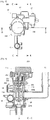
- FIG. 1
- is a schematic diagram illustrating a configuration of a boiler having a check valve integrated with a water pipe line according to the present disclosure.
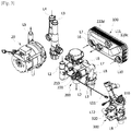
- FIG. 2
- is a perspective view in which major parts of the boiler according to the present disclosure are coupled.
- FIG. 3
- is a perspective view illustrating separated module units of
FIG. 2 . - FIG. 4
- is an exploded perspective view of a heat exchanger shown in
FIG. 3 . - FIG. 5
- is a front view of the heat exchanger.
- FIG. 6
- is a cross-sectional view taken along A-A line of
FIG. 5 . - FIG. 7
- is a cross-sectional view taken along B-B line of
FIG. 5 . - FIG. 8
- is a plan view of a first water pipe module shown in
FIG. 3 . - FIG. 9
- is a cross-sectional view taken along C-C line of
FIG. 8 . - FIG. 10
- is a cross-sectional view taken along D-D line of
FIG. 8 . - FIG. 11
- is a cross-sectional view taken along E-E line of
FIG. 8 . - FIG. 12
- is an exploded perspective view of a check valve shown in
FIG. 11 . - FIG. 13
- is a diagram illustrating a flow passage of heating water in a heating mode of the boiler according to the present disclosure.
- FIG. 14
- is a diagram illustrating flow passages of the heating water and direct water/warm water in a warm water mode of the boiler according to the present disclosure.
- FIG. 15
- is a diagram illustrating a flow passage in which heating water bypasses to prevent generation of overpressure when a heating pipe at a heating water supply or a hot water heat exchanger is blocked in the boiler of the present disclosure.
- Hereinafter, configurations and operations for preferred embodiments of the present disclosure will be described in detail with reference to the accompanying drawings.
- Referring to
FIGS. 1 to 3 , a boiler according to one embodiment of the present disclosure is configured to include anexpansion tank 10 configured to store heating water returning via a place to be heated in a heating mode or heating water circulating inside the boiler in a warm water mode, a circulatingpump 20 configured to forcibly transfer the heating water discharged from theexpansion tank 10 in one direction, amain heat exchanger 30 configured to heat the heating water, which flows in via the circulatingpump 20, by combustion heat of a burner, a hotwater heat exchanger 100 configured to supply warm water through heat exchange between the heating water heated in themain heat exchanger 30 and direct water, a firstwater pipe module 200 configured to provide a passage through which the heating water supplied from themain heat exchanger 30 returns via the place to be heated or the hotwater heat exchanger 100, and a bypass passage for preventing generation of overpressure inside a heating pipe, and a secondwater pipe module 300 configured to provide passages of direct water and warm water passing the hotwater heat exchanger 100, and a supplement passage of the heating water. - Further, a reference numeral 'L1' shown in
FIG. 1 represents a heating water main supply pipe through which the heating water, which is heated in the main heat exchanger 30, is provided to a three-way valve 210, a reference numeral 'L2' represents a heating water supply pipe through which the heating water is supplied from the three-way valve 210 to the place to be heated in a heating mode, a reference numeral 'L3' represents a heating water return pipe through which heating water passing the place to be heated returns to the expansion tank 10, a reference numeral 'L4' represents a heating water circulating inlet pipe through which the heating water discharged from the expansion tank 10 is supplied to the circulating pump 20, a reference numeral 'L5' represents a heating water circulating outlet pipe through which the heating water being forcibly transferred from the circulating pump 20 is supplied to the main heat exchanger 30, a reference numeral 'L6' represents a heating water inlet pipe through which the heating water is supplied from the three-way valve 210 to the hot water heat exchanger 100, a reference numeral 'L7' represents a heating water outlet pipe through which the heating water is connected from the hot water heat exchanger 100 to the heating water return pipe L3, a reference numeral 'L8' represents a bypass pipe through which the heating water is discharged from the three-way valve 210 to the heating water return pipe L3 so as to prevent an overpressure state inside the heating pipe, a reference numeral 'L9' represents a direct water supply pipe through which direct water flows inside the boiler, a reference numeral 'L10' represents a direct water inlet pipe through which the direct water flows from a flow rate sensor 310, which senses a flow of the direct water, to the hot water heat exchanger 100, a reference numeral 'L11' represents a warm water supply pipe through which warm water heated in the hot water heat exchanger 100 is supplied to the place to be heated, and a reference numeral 'L12 represents a water supplement pipe through which the direct water flowing into the direct water supply pipe L9 flows into the expansion tank 10. - As shown in
FIG. 3 , in the present disclosure, the firstwater pipe module 200 and the secondwater pipe module 300 are respectively configured with module units and are detachably assembled into the hotwater heat exchanger 100 so as to be configured to simplify a structure of each of a water pipe for the heating water and a water pipe for the direct water/warm water. As a configuration for the described above, the firstwater pipe module 200 is provided with the three-way valve 210 configured to change a passage of heating water so as to selectively supply the heating water, which is heated in themain heat exchanger 30 and then supplied through the heating water main supply pipe L1, to the place to be heated through the heating water supply pipe L2 and to the hotwater heat exchanger 100 through the heating water inlet pipe L6, the bypass pipe L8 configured to connect the three-way valve 210 to the heating water return pipe L3, and acheck valve 220 provided at the bypass pipe L8 and configured to enable fluid to flow in only one direction from the three-way valve 210 to the heating water return pipe L3 when a pipeline of the heating water supply pipe L2 connected to the place to be heated or a pipeline of the heating water inlet pipe L6 connected to the hotwater heat exchanger 100 is blocked to cause generation of overpressure inside the heating pipe. - The second
water pipe module 300 is provided with theflow rate sensor 310 configured to sense a flow of direct water which flows in through the direct water supply pipe L9 in a warm water mode, the water supplement pipe L12 configured to receive direct water to supplement heating water when the heating water is insufficient, and a make-upwater valve 320 provided at a pipeline of the water supplement pipe L12 and configured to suspend a flow of the direct water. - Referring to
FIGS. 4 to 7 , the hotwater heat exchanger 100 is configured with a plate-type heat exchanger in which a heating water passage P1 and a direct water passage P2 are formed to be separated from each other by stacking a plurality ofplates FIGS. 3 and4 , a solid line arrow represents a flow passage of the heating water, a dotted line arrow represents a flow passage of each of the direct water and the warm water, andFIGS. 6 and 7 show that the heating water passage P1 and the direct water passage P2 are alternately formed at every layer to be spaced apart from each other. - Referring to
FIG. 4 , the plurality ofplates flat plate 120 is stacked in rear of thefront plate 110, and the first plate 130 (that is, 130-1, 130-2, 130-3, and 130-4) and the second plate 140 (that is, 140-1, 140-2, 140-3, and 140-4) are alternately stacked in rear of theflat plate 120. That is, the first plate 130-1, the second plate 140-1, the first plate 130-2, the second plate 140-2, the first plate 130-3, the second plate 140-3, the first plate 130-4, and the second plate 140-4 are sequentially stacked in rear of theflat plate 120. However, in the present embodiment, a case in which thefirst plate 130 and the second plate 140 are configured with four pairs of plates is exemplified, but the number of thefirst plate 130 and the second plate 140, which are to be stacked, may be differently configured from the described above. - Further, the first
passage changing plate 150 configured to change a passage of the warm water from a rear direction toward a front direction, and the secondpassage changing plate 160 configured to change a passage of the heating water from a rear direction toward a front direction are stacked in rear of thefirst plate 130 and the second plate 140. - The plurality of
plates flat surface parts flange parts flat surface parts flange parts - To enable the hot
water heat exchanger 100 to be easily attached to or detached from the firstwater pipe module 200 and the secondwater pipe module 300, each of which is configured in a module unit, adual passage structure discharge guide part 110c and a warm waterdischarge guide part 110d, which respectively form a discharge passage of the heating water and a discharge passage of the warm water, are formed at thefront plate 110 of the hotwater heat exchanger 100. - As a configuration for the described above, a heating
water inlet hole 111 connected to the heating water inlet pipe L6 is formed at a lower one side of thefront plate 110, a heatingwater outlet hole 112 connected to the heating water outlet pipe L7 is formed at one side of the heatingwater inlet hole 111, and the heating waterdischarge guide part 110c is formed to guide heating water, which passes the heating water passage P1 and then is discharged in the front direction toward an upper another side of thefront plate 110, to the heatingwater outlet hole 112. - Further, a direct
water inlet hole 113 connected to the direct water inlet pipe L10 is formed at a lower another side of thefront plate 110, a warmwater outlet hole 114 connected to the warm water supply pipe L11 is formed at a position of an upper portion of thefront plate 110, which is in contiguity with the directwater inlet hole 113 among regions at which the heating waterdischarge guide part 110c is not formed, and the warm waterdischarge guide part 110d is formed to guide warm water, which passes the direct water passage P2 and then is discharged in the front direction toward an upper one side of thefront plate 110, to the warmwater outlet hole 114. - In the
flat plate 120 stacked in rear of thefront plate 110, a heatingwater inlet hole 121 is formed at a lower one side of theflat plate 120, a heatingwater outlet hole 122 is formed at an upper another side of theflat plate 120, a directwater inlet hole 123 is formed at a lower another side of theflat plate 120, and a warm water outlet hole 124 is formed at an upper one side of theflat plate 120. An edge of each of the heating waterdischarge guide part 110c and the warm water discharge guide part 100d is tightly welded to theflat surface part 120a of theflat plate 120, and an inner part of the edge of each of the heating waterdischarge guide part 110c and the warm water discharge guide part 100d forwardly protrudes to form discharge passages of the heating water and the warm water. - In the
first plate 130 stacked in rear of theflat plate 120, a heatingwater inlet hole 131 is formed at a lower one side of thefirst plate 130, a heatingwater outlet hole 132 is formed at an upper another side of thefirst plate 130, a directwater inlet hole 133 is formed at a lower another side of thefirst plate 130, and a warmwater outlet hole 134 is formed at an upper one side of thefirst plate 130. Further,boss parts 131a and 132a, which forwardly protrude to respectively come into tight contact with edges of the heatingwater inlet hole 121 and the heatingwater outlet hole 122 of theflat plate 120, are respectively formed at edges of the heatingwater inlet hole 131 and the heatingwater outlet hole 132 of thefirst plate 130, and a plurality offirst beads 135, each of which is bent to one side, are formed to protrude toward the front direction at theflat surface part 130a of thefirst plate 130. - In the second plate 140 stacked in rear of the
first plate 130, a heatingwater inlet hole 141 is formed at a lower one side of the second plate 140, a heatingwater outlet hole 142 is formed at an upper another side of the second plate 140, a directwater inlet hole 143 is formed at a lower another side of the second plate 140, and a warmwater outlet hole 144 is formed at an upper one side of the second plate 140. Further,boss parts water inlet hole 133 and the warmwater outlet hole 134 of thefirst plate 130, are respectively formed at edges of the directwater inlet hole 143 and the warmwater outlet hole 144 of the second plate 140, and a plurality ofsecond beads 145, each of which is bent in a direction opposite to that of each of thefirst beads 135, are formed at theflat surface part 140a of the second plate 140. - The heating water passage P1 and the direct water passage P2 may be alternately separately formed at every layer by the
boss parts 131a and 132a formed at thefirst plate 130 and theboss parts boss parts 131a and 132a formed at thefirst plate 130 enable the direct water to flow between theflat plate 120 and thefirst plate 130 and block the heating water from flowing therebetween such that the direct water passage P2 is formed, and theboss parts first plate 130 and the second plate 140 and block the direct water from flowing therebetween such that the heating water passage P1 is formed. - Further, when the
first plate 130 and the second plate 140 are overlapped with each other, generation of turbulence is promoted to a flow of fluid passing and flowing through overlapped gaps between thefirst beads 135 formed at thefirst plate 130 and thesecond beads 145 formed at the second plate 140 such that heat exchange efficiency between the heating water and the direct water is improved. - The
first plate 130 and the second plate 140 are alternately overlapped in plural, a heatingwater inlet hole 151 is formed at a lower one side of the firstpassage changing plate 150, which is stacked in rear of the second plate 140-4 disposed at a rearmost position, a heatingwater outlet hole 152 is formed at an upper another side of the firstpassage changing plate 150, and a lower another side and an upper one side are configured in a shape blocked in the front and rear directions, such that a passage of the direct water is changed toward the front direction at the direct water passage P2 between the second plate 140-4 and the firstpassage changing plate 150. Further, a plurality offirst beads 155, each of which is bent to one side and forwardly protrudes, are formed at theflat surface part 150a of the firstpassage changing plate 150. - An entire region of the
flat surface part 160a of the secondpassage changing plate 160, which is stacked in rear of the firstpassage changing plate 150, is configured in a shape blocked in the front and rear directions such that a passage of the heating water is changed toward the front direction at the heating water passage P1 between the firstpassage changing plate 150 and the secondpassage changing plate 160. Further, a plurality ofsecond beads 165, each of which is bent to another side and forwardly protrudes, are formed at theflat surface part 160a of the secondpassage changing plate 160. - In accordance with such a configuration of the hot
water heat exchanger 100, the heating water passage P1 communicating from the lower one side to the upper another side and the direct water passage P2 communicating from the lower another side to the upper one side are alternately formed inside the plurality of stackedplates first beads second beads - Further, the
front plate 110 is provided with the heating waterdischarge guide part 110c configured to guide the heating water, which is discharged after passing the heating water passage P1, to the heatingwater outlet hole 112 formed to be close to one side of the heatingwater inlet hole 111, and the warm waterdischarge guide part 110d configured to guide the warm water, which is discharged after passing the direct water passage P2, to the warmwater outlet hole 114 formed to be maximally close to the directwater inlet hole 113, so that the firstwater pipe module 200 and the secondwater pipe module 300, which are described above, may be configured to be easily attached to or detached from the hotwater heat exchanger 100. - Also, a gap between the heating water inlet pipe L6 and the heating water outlet pipe L7, which are connected to the hot
water heat exchanger 100, is formed to be narrow such that a size of the firstwater pipe module 200, which is connected to the heating water inlet pipe L6 and the heating water outlet pipe L7, may be miniaturized. - Similarly, a gap between the direct water inlet pipe L10 and the warm water supply pipe L11, which are connected to the hot
water heat exchanger 100, is also formed to be narrow such that a size of the secondwater pipe module 300, which is connected to the direct water inlet pipe L10 and the warm water supply pipe L11, may also be miniaturized. - In this case, the heating
water inlet hole 111 and the heatingwater outlet hole 112 are formed at one side of the hotwater heat exchanger 100, and the directwater inlet hole 113 and the warmwater outlet hole 114 are formed at positions that are spaced apart from a region, at which the heatingwater inlet hole 111 and the heatingwater outlet hole 112 are formed, to another side thereof, so that the firstwater pipe module 200 and the secondwater pipe module 300 may be respectively coupled to both side parts of the hotwater heat exchanger 100. - Hereinafter, a structure for a passage change and a bypass of the heating water, which is provided inside the first
water pipe module 200, will be described in more detail with reference toFIGS. 8 and12 . - The first
water pipe module 200 is provided with the three-way valve 210 configured to selectively change a passage of the heating water, which flows from the heating water main supply pipe L1 connected to one side of ahousing 201, to the heating water supply pipe L2 connected to a lower side of thehousing 201, or to the heating water inlet pipe L6 connected to the other side of thehousing 201, the bypass pipe L8 communicates with a lateral wall of thehousing 201, which is located at one side of the three-way valve 210, and thecheck valve 220 is provided at a pipeline of the bypass pipe L8. - As described above, pipelines connected to the heating water main supply pipe L1, the heating water supply pipe L2, the heating water inlet pipe L6, and the bypass pipe L8 are integrally formed at the
housing 201 of the firstwater pipe module 200 such that a water pipe structure of the heating water may be compactly configured, and further a pipeline length of a water pipe may be shortened in comparison with a conventional structure in which water pipes are individually installed, and a pressure loss of the heating water may be reduced such that thermal efficiency of the boiler may be improved. - The three-
way valve 210 is configured to include amotor 211, acam member 212 coupled to a rotating shaft of themotor 211, ashaft 213 having an upper end that is supported and raised by thecam member 212, avalve body 214 coupled to a lower outer circumferential surface of theshaft 213, anelastic member 215 configured to apply an upward elastic force to theshaft 213 to maintain a state in which the upper end of theshaft 213 comes into contact with a lower end of thecam member 212, and avalve seat 216 in which anupper hook protrusion 216a configured to hook an upper end of thevalve body 214 and alower hook protrusion 216b configured to hook a lower end of thevalve body 214 according to rising of theshaft 213 are formed, and configured to selectively change a passage of the heating water, which flows inside thehousing 201 through the heating water main supply pipe L1, to the heating water supply pipe L2 and the heating water inlet pipe L6. - The bypass pipe L8 is formed to penetrate a lateral wall of the
housing 201 in a region between theupper hook protrusion 216a and thelower hook protrusion 216b of thevalve seat 216, thereby communicating with the heating water return pipe L3. - Referring to
FIGS. 11 and12 , thecheck valve 220 is configured to include abody part 221 at which aninlet 221a communicating with the bypass pipe L8, which is formed at the lateral wall of thehousing 201, is formed, avalve body 222 configured with ashaft part 222a and avalve part 222b, which are inserted inside thebody part 221, and configured to open and block a passage of the heating water flowing in through theinlet 221a, anelastic member 223 disposed at an outer circumference of theshaft part 222a and configured to provide an elastic force to thevalve part 222b in a direction of blocking a passage of the heating water, and acoupler 224 in which aninsertion recess 224a coupled to theshaft part 222a of thevalve body 222 is formed, and coupled to thebody part 221. - In accordance with such a configuration of the
check valve 220, only when water pressure of the heating water flowing into theinlet 221a of thebody part 221 exceeds the elastic force of theelastic member 223 to cause generation of overpressure inside a heating pipe, thevalve body 222 opens a passage of the heating water and thus the heating water passes the bypass pipe L8 to flow to the heating water return pipe L3, whereas, when the water pressure of the heating water acts as being equal to or less than the elastic force of theelastic member 223, thevalve body 222 maintains a state of blocking the passage of the heating water. - Hereinafter, flow passages of the heating water and the warm water in a heating mode and a warm water mode of the boiler and when overpressure is generated will be described with reference to
FIGS. 13 to 15 . - Referring to
FIG. 13 , in a heating mode, heating water heated in themain heat exchanger 30 is supplied to the three-way valve 210 along the heating water main supply pipe L1, and, in this case, the three-way valve 210 is set to be blocked to the heating water inlet pipe L6 and to be open to the heating water supply pipe L2, so that the heating water passing the three-way valve 210 is supplied to a place to be heated along the heating water supply pipe L2. The heating water, which transfers heat while passing the place to be heated, flows into theexpansion tank 10 through the heating water return pipe L3, and heating water, which is stored in theexpansion tank 10, is supplied to themain heat exchanger 30 along the heating water circulating inlet pipe L4 and the heating water circulating outlet pipe L5 by an operation of the circulatingpump 20, and circulates and flows after it is heated in themain heat exchanger 30. - Referring to
FIG. 14 , in a warm water mode, heating water heated in themain heat exchanger 30 is supplied to the three-way valve 210 along the heating water main supply pipe L1, and, in this case, the three-way valve 210 is set to be blocked to the heating water supply pipe L2 and to be open to the heating water inlet pipe L6, so that the heating water passing the three-way valve 210 is supplied to the hotwater heat exchanger 100 along the heating water inlet pipe L6. The heating water, which transfers heat to direct water in the hotwater heat exchanger 100, flows into theexpansion tank 10 along the heating water outlet pipe L7 and the heating water return pipe L3, and heating water, which is stored in theexpansion tank 10, is supplied to themain heat exchanger 30 along the heating water circulating inlet pipe L4 and the heating water circulating outlet pipe L5 by an operation of the circulatingpump 20, and circulates and flows after it is heated in themain heat exchanger 30. - At the same time, the direct water, which flows in through the direct water supply pipe L9, is supplied to the hot
water heat exchanger 100 through the direct water inlet pipe L10 via theflow rate sensor 310, and warm water, which is heated by receiving the heat transferred from the heating water while passing the hotwater heat exchanger 100, is supplied to a place that requires warm water through the warm water supply pipe L11. - Referring to
FIG. 15 , the heating water supply pipe L2, which is connected from the three-way valve 210 to the place to be heated, is blocked in the heating mode, or the heating water inlet pipe L6, which is connected from the three-way valve 210 to the hotwater heat exchanger 100, is blocked in the warm water mode and, when overpressure is generated inside the heating pipe, thecheck valve 220 provided at the pipeline of the bypass pipe L8 is open, and thus the heating water, which is supplied to the three-way valve 210 through the heating water main supply pipe L1, may flow into theexpansion tank 10 through the bypass pipe L8 and the heating water return pipe L3, thereby releasing the overpressure generated inside the heating pipe. Therefore, damage to other components in addition to the circulatingpump 20, which is caused when the overpressure is generated inside the heating pipe, may be prevented to improve durability. - Although a case in which heat exchange between the heating water and the direct water is performed in the hot
water heat exchanger 100 is exemplified in the present disclosure, the hotwater heat exchanger 100 may be applicable to a case in which heat exchange is performed between two different fluids in addition to water. - As described above, the present disclosure is not limited to the above described embodiments, and modified implementations can be devised by those skilled in the art without departing from the technical spirit of the present disclosure as defined in the appended claims. Therefore, such modified implementations should be construed to fall within the scope of the present disclosure.
| 10: expansion tank | 20: circulating pump |
| 30: main heat exchanger | 100: hot water heat exchanger |
| 110: |
|
| 110a, 120a, 130a, 140a, 150a, and 160a: |
|
| 110b, 120b, 130b, 140b, 150b, and 160b: |
|
| 110c: heating water |
|
| 110d: warm water |
|
| 111, 121, 131, 141, and 151: heating |
|
| 131a, 132a, 143a, 144a, 151a, and 161a: |
|
| 112, 122, 132, 142, and 152: heating |
|
| 113, 123, 133, and 143: direct |
|
| 114, 124, 134, and 144: warm water outlet holes | |
| 120: flat plate | 130: |
| 135 and 155: |
145 and 165: second beads |
| 140: second plate | 150: first passage changing plate |
| 160: second passage changing plate | |
| 200: first water pipe module | |
| 201: housing | 210: three-way valve |
| 211: motor | 212: cam member |
| 213: shaft | 214: valve body |
| 215: elastic member | 216: |
| 216a and 216b: hook protrusions | 220: check valve |
| 221: body part | 222: valve body |
| 223: elastic member | 224: coupler |
| 300: second water pipe module | 310: flow rate sensor |
| 320: make-up water valve pipe | L1: heating water main supply |
| L2: heating water supply pipepipe | L3: heating water return |
| L4: heating water circulating inlet pipe | |
| L5: heating water circulating outlet pipe | |
| L6: heating water inlet pipepipe | L7: heating water outlet |
| L8: bypass pipe | L9: direct water supply pipe |
| L10: direct water inlet pipe | L11: warm water supply pipe |
| L12: water supplement pipe | P1: heating water passage |
| P2: direct water passage |
Claims (11)
- A boiler having a check valve integrated with a water pipe line, which is provided with a main heat exchanger (30) configured to heat heating water by combustion heat of a burner, and a hot water heat exchanger (100) configured to supply warm water through heat exchange between the heating water heated in the main heat exchanger (30) and direct water, comprising:a three-way valve (210) configured to change a passage of the heating water so as to selectively supply the heating water heated in the main heat exchanger (30) to a place to be heated and the hot water heat exchanger (100) ;a bypass pipe (L8) configured to connect the three-way valve (210) to a heating water return pipe (L3) that connects the place to be heated to the main heat exchanger (30); anda check valve (220) provided at a pipeline of the bypass pipe (L8) and configured to enable fluid to flow in only one direction from the three-way valve (210) to the heating water return pipe (L3) when overpressure is generated resulting from blocking of a heating pipe (L2) connected to the place to be heated or a heating pipe (L6) connected to the hot water heat exchanger (100),wherein the three-way valve (210), the bypass pipe (L8), and the check valve (220) are integrally provided inside the same water pipe module.
- The boiler of claim 1, wherein a circulating pump (20) configured to forcibly transfer the heating water toward the main heat exchanger (30) in one direction is provided at heating pipes (L4) and (L5) connected to the heating water return pipe (L3).
- The boiler of claim 1, wherein, when the overpressure is generated resulting from blocking of the heating pipe (L2) connected to the place to be heated or the heating pipe (L6) connected to the hot water heat exchanger (100), the heating water heated in the main heat exchanger (30) is supplied to the three-way valve (210), flows into the bypass pipe (L8) communicating with one side of the three-way valve (210), passes the check valve (220), and then flows into an expansion tank (10), and heating water stored in the expansion tank (10) circulates and flows to the main heat exchanger (30) by a circulating pump (20) such that overpressure is prevented from being generated inside the heating pipe.
- The boiler of claim 1, wherein the hot water heat exchanger (100) is configured with a plate-type heat exchanger in which a heating water passage (P1) and a direct water passage (P2) are formed to be separated from each other by stacking a plurality of plates and thus the heating water and the direct water are able to alternately flow at every layer inside the stacked plates to thereby cause heat exchange between the heating water and the direct water,wherein a front plate (110), which is located at a front side among the plurality of plates, is provided with a heating water discharge guide part (110c) in which a heating water outlet pipe (L7) is configured to be located close to a heating water inlet pipe (L6) to form a passage of the heating water so as to enable the heating water to flow into the heating water inlet pipe (L6), which is formed at a lower one side of the front plate (110), and to be discharged after passing the heating water passage (P1), anda warm water discharge guide part (110d) in which a warm water supply pipe (L11) is configured to be located close to a direct water inlet pipe (L10) to form a passage of the warm water so as to enable the direct water to flow into the direct water inlet pipe (L10), which is formed at a lower another side of the front plate (110), to be discharged after passing the direct water passage (P2), andwherein the boiler includes:a first water pipe module (200) having one side which is detachably assembled into the heating water inlet pipe (L6) and the heating water outlet pipe (L7) of the hot water heat exchanger (100), provided with the three-way valve (210), the bypass pipe (L8), and the check valve (220) which are integrated therewith, and configured to provide a passage through which the heating water, which is supplied from the main heat exchanger (30), returns via the place to be heated or the hot water heat exchanger (100); anda second water pipe module (300) having one side which is detachably assembled into the direct water inlet pipe (L10) and the warm water supply pipe (L11), and configured to provide a passage through which each of the direct water and the warm water passes the hot water heat exchanger (100).
- The boiler of claim 4, wherein a heating water inlet hole (111) connected to the heating water inlet pipe (L6) is formed at the lower one side of the front plate (110),a heating water outlet hole (112) connected to the heating water outlet pipe (L7) is formed at one side of the heating water inlet hole (111), andthe heating water discharge guide part (110c) is formed to guide the heating water, which is discharged in a front direction toward an upper another side of the front plate (110), to the heating water outlet hole (112).
- The boiler of claim 5, wherein a direct water inlet hole (113) connected to the direct water inlet pipe (L10) is formed at a lower another side of the front plate (110),a warm water outlet hole (114) is formed at an upper portion of the front plate (110) and connected to the warm water supply pipe (L11) at a position of a region, at which the heating water discharge guide part (110c) is not formed, close to the direct water inlet hole (113), andthe warm water discharge guide part (110d) is formed to guide the warm water, which is discharged in the front direction toward an upper one side of the front plate (110), to the warm water outlet hole (114).
- The boiler of claim 6, wherein a flat plate (120) is stacked in rear of the front plate (110), wherein a heating water inlet hole (121) is formed at a lower one side of the flat plate (120), a heating water outlet hole (122) is formed at an upper another side of the flat plate (120), a direct water inlet hole (123) is formed at a lower another side of the flat plate (120), and a warm water outlet hole (124) is formed at an upper one side of the flat plate (120), anda circumference of an edge of each of the heating water discharge guide part (110c) and the warm water discharge guide part (100d) comes into tight contact with the flat plate (120) and an inner part of the edge protrudes in the front direction to form a discharge passage of each of the heating water and the warm water.
- The boiler of claim 7, wherein a plurality of first plates (130) and second plates (140), each of which is formed to enable boss parts located in a diagonal direction to be intersected in front and rear directions, are alternately stacked in rear of the flat plate (120), thereby alternately forming the heating water passage (P1) and the direct water passage (P2), anda plurality of first beads (135) and second beads (145), which are bent in opposite directions, are respectively formed at the plurality of first plates (130) and second plates (140) to be configured to enable fluid to flow through overlapped gaps between the plurality of first beads (135) and second beads (145).
- The boiler of claim 8, wherein a first passage changing plate (150) configured to change a passage of the direct water from the rear direction toward the front direction, and a second passage changing plate (160) configured to change a passage of the heating water from the rear direction toward the front direction are sequentially stacked in rear of the second plate (140) that is stacked at a rearmost position.
- The boiler of claim 9, wherein a heating water inlet hole (151) is formed at a lower one side of the first passage changing plate (150), a heating water outlet hole (152) is formed at an upper another side of the first passage changing plate (150), and a lower another side and an upper one side are formed in a shape blocked in the front and rear directions, andan entire region of the second passage changing plate (150) is configured in a shape blocked in the front and rear directions.
- The boiler of claim 4, wherein the second water pipe module (300) is provided with a flow rate sensor (310) configured to sense a flow of the direct water flowing into the direct water inlet pipe (L10), a water supplement pipe (L12) configured to receive the direct water to supplement the heating water when the heating water is insufficient, and a make-up water valve (320) provided at a pipeline of the water supplement pipe (L12) and configured to suspend the flow of the direct water.
Applications Claiming Priority (2)
| Application Number | Priority Date | Filing Date | Title |
|---|---|---|---|
| KR1020140161462A KR101639188B1 (en) | 2014-11-19 | 2014-11-19 | Boiler having check valve integrated water pipe conduit |
| PCT/KR2015/012283 WO2016080715A1 (en) | 2014-11-19 | 2015-11-16 | Boiler having check valve integrated with water pipe line |
Publications (2)
| Publication Number | Publication Date |
|---|---|
| EP3222929A1 true EP3222929A1 (en) | 2017-09-27 |
| EP3222929A4 EP3222929A4 (en) | 2018-08-08 |
Family
ID=56014183
Family Applications (1)
| Application Number | Title | Priority Date | Filing Date |
|---|---|---|---|
| EP15860937.0A Withdrawn EP3222929A4 (en) | 2014-11-19 | 2015-11-16 | Boiler having check valve integrated with water pipe line |
Country Status (5)
| Country | Link |
|---|---|
| EP (1) | EP3222929A4 (en) |
| KR (1) | KR101639188B1 (en) |
| CN (1) | CN107076461B (en) |
| RU (1) | RU2676172C2 (en) |
| WO (1) | WO2016080715A1 (en) |
Families Citing this family (4)
| Publication number | Priority date | Publication date | Assignee | Title |
|---|---|---|---|---|
| KR101946630B1 (en) * | 2016-12-23 | 2019-02-11 | 주식회사 경동나비엔 | Valve capable of changing specifications and Boiler having the same |
| CN112483695B (en) * | 2020-11-12 | 2021-12-17 | 浙江春晖智能控制股份有限公司 | Self-positioning, high-sealing and large-flow three-way valve |
| CN115523531A (en) * | 2021-06-24 | 2022-12-27 | 丹佛斯有限公司 | One-piece heating station with bypass |
| KR102712805B1 (en) * | 2021-12-31 | 2024-10-02 | 오영한 | Electric boiler |
Family Cites Families (21)
| Publication number | Priority date | Publication date | Assignee | Title |
|---|---|---|---|---|
| AT398857B (en) * | 1991-10-31 | 1995-02-27 | Vaillant Gmbh | METHOD FOR CONTROLLING A HEATING DEVICE AND HEATING DEVICE FOR IMPLEMENTING THE METHOD |
| IT1284431B1 (en) * | 1996-03-22 | 1998-05-21 | Fugas Srl | HYDRAULIC UNIT WITH INTEGRATED PUMP FOR MIXED HEATING AND SANITARY WATER SYSTEMS |
| KR19980016052A (en) * | 1996-08-26 | 1998-05-25 | 배순훈 | Overpressure discharge structure in the case of heating piping closure of gas boiler using bidirectional circulation pump |
| EP0916901A1 (en) * | 1997-11-11 | 1999-05-19 | IABER S.p.A. | Scale reducing device for gas-fired boilers |
| KR100301105B1 (en) | 1998-08-18 | 2001-10-29 | 최성봉 | Boiler hot water supply device |
| EP0981031A3 (en) * | 1998-08-18 | 2002-07-31 | ALCO Corporation of Namdong Industrial Area 156BL/10LT | Heating water flow circulation and instantaneous hot sanitary water supply apparatus in a combi-boiler |
| KR20020070992A (en) * | 1999-12-14 | 2002-09-11 | 림 오스트레일리아 피티와이 리미티드 | Water heater and water heater component construction |
| FR2813950B1 (en) * | 2000-09-14 | 2002-11-15 | Chaffoteaux Et Maury | HYDRAULIC DISTRIBUTOR VALVE FOR A SYSTEM FOR PRODUCING HOT HEATING WATER AND DOMESTIC HOT WATER |
| KR100645734B1 (en) * | 2005-12-14 | 2006-11-15 | 주식회사 경동나비엔 | Heat exchanger of condensing boiler for heating / hot water |
| ITTO20060177A1 (en) * | 2006-03-09 | 2007-09-10 | Eltek Spa | HYDRAULIC DEVICE, HYDRAULIC EQUIPMENT, HYDRAULIC SYSTEM AND METHOD FOR ITS USE |
| PL1884720T3 (en) * | 2006-07-28 | 2016-08-31 | Grundfos Management As | Assembly for a compact heating installation |
| EP1884717B1 (en) * | 2006-07-28 | 2016-01-13 | Grundfos Management A/S | Heating system |
| JP4454038B2 (en) * | 2008-04-03 | 2010-04-21 | 株式会社テスク | Electric hot water circulation heating system |
| ITBO20080456A1 (en) * | 2008-07-21 | 2010-01-22 | O T M A S N C Di Spaggiari & C | HYDRAULIC VALVE GROUP FOR MURAL BOILERS |
| EP2397777B1 (en) * | 2010-06-19 | 2016-08-03 | Grundfos Management A/S | Housing unit for a heating system |
| JP2012009778A (en) * | 2010-06-28 | 2012-01-12 | Tdk Corp | Wiring structure and electronic component package |
| JP2012097787A (en) | 2010-10-29 | 2012-05-24 | Time Engineering Co Ltd | Drain valve with overpressure relief valve |
| JP2012141096A (en) * | 2010-12-28 | 2012-07-26 | Mitsubishi Heavy Ind Ltd | Method for manufacturing hot-water heater, and hot-water heater manufactured thereby |
| KR101370937B1 (en) * | 2011-07-04 | 2014-03-10 | 주식회사 경동나비엔 | Gas water heater and hot water supplier |
| CN202452702U (en) * | 2012-01-04 | 2012-09-26 | 陈群 | Waterway device used for fuel gas heating water furnace |
| KR101898018B1 (en) * | 2012-06-19 | 2018-09-12 | 한온시스템 주식회사 | Plate type heat exchanger |
-
2014
- 2014-11-19 KR KR1020140161462A patent/KR101639188B1/en active Active
-
2015
- 2015-11-16 RU RU2017121072A patent/RU2676172C2/en active
- 2015-11-16 EP EP15860937.0A patent/EP3222929A4/en not_active Withdrawn
- 2015-11-16 CN CN201580059743.9A patent/CN107076461B/en active Active
- 2015-11-16 WO PCT/KR2015/012283 patent/WO2016080715A1/en not_active Ceased
Also Published As
| Publication number | Publication date |
|---|---|
| RU2017121072A3 (en) | 2018-12-20 |
| RU2676172C2 (en) | 2018-12-26 |
| EP3222929A4 (en) | 2018-08-08 |
| CN107076461B (en) | 2020-01-31 |
| KR20160059678A (en) | 2016-05-27 |
| KR101639188B1 (en) | 2016-07-13 |
| RU2017121072A (en) | 2018-12-20 |
| WO2016080715A1 (en) | 2016-05-26 |
| CN107076461A (en) | 2017-08-18 |
Similar Documents
| Publication | Publication Date | Title |
|---|---|---|
| KR101283591B1 (en) | Heat exchanger for vehicle | |
| KR101526427B1 (en) | Heat exchanger for vehicle | |
| KR101339250B1 (en) | Heat exchanger for vehicle | |
| CN106288868B (en) | Heat exchanger | |
| CA2902679C (en) | Plate heat exchanger and method for constructing multiple passes in the plate heat exchanger | |
| US10302319B2 (en) | Storage tank with condenser | |
| EP2741041B1 (en) | Plate-type heat exchanger and heat pump device | |
| JPWO2012063355A1 (en) | Plate heat exchanger and heat pump device | |
| EP2672193A1 (en) | Boiler having integrated nitrogen tank and heat exchanger | |
| EP2650633A2 (en) | Plate-type heat exchanger, method of manufacturing the same, and heat pump device | |
| KR20130067099A (en) | Automotive combination heat exchanger | |
| CN107076461B (en) | Boiler with check valve integrated with water pipe | |
| CN106246955A (en) | Slidingtype reversal valve and refrigerating circulation system | |
| JP5819592B2 (en) | Plate heat exchanger and heat pump device | |
| EP4246075A3 (en) | Heat exchanger for heat pump applications | |
| KR101675739B1 (en) | Boiler having assembly structure of modularized water pipe parts | |
| JP5898124B2 (en) | Water dispenser | |
| US20200166282A1 (en) | Plate-type heat exchanger and heat source apparatus | |
| KR20200061715A (en) | Boiler with stable hot water supply | |
| JP5046748B2 (en) | Gas cooler for hot water system | |
| EP2045554A2 (en) | Radiator with radiating plate having high efficiency | |
| CN116817644A (en) | Plate heat exchanger | |
| KR102847150B1 (en) | A Plate Heat exchanger for heat pump | |
| KR200337486Y1 (en) | A boiler with the defference of hydraulic pressure type a 3-way valve | |
| KR20150125552A (en) | A heat exchanger |
Legal Events
| Date | Code | Title | Description |
|---|---|---|---|
| PUAI | Public reference made under article 153(3) epc to a published international application that has entered the european phase |
Free format text: ORIGINAL CODE: 0009012 |
|
| 17P | Request for examination filed |
Effective date: 20170615 |
|
| AK | Designated contracting states |
Kind code of ref document: A1 Designated state(s): AL AT BE BG CH CY CZ DE DK EE ES FI FR GB GR HR HU IE IS IT LI LT LU LV MC MK MT NL NO PL PT RO RS SE SI SK SM TR |
|
| AX | Request for extension of the european patent |
Extension state: BA ME |
|
| DAV | Request for validation of the european patent (deleted) | ||
| DAX | Request for extension of the european patent (deleted) | ||
| A4 | Supplementary search report drawn up and despatched |
Effective date: 20180709 |
|
| RIC1 | Information provided on ipc code assigned before grant |
Ipc: F24D 3/10 20060101ALI20180703BHEP Ipc: F24H 9/20 20060101AFI20180703BHEP Ipc: F24H 9/14 20060101ALI20180703BHEP Ipc: F24D 3/08 20060101ALI20180703BHEP |
|
| STAA | Information on the status of an ep patent application or granted ep patent |
Free format text: STATUS: THE APPLICATION HAS BEEN WITHDRAWN |
|
| 18W | Application withdrawn |
Effective date: 20190116 |