EP3222880A1 - Gear drive device - Google Patents
Gear drive device Download PDFInfo
- Publication number
- EP3222880A1 EP3222880A1 EP17162455.4A EP17162455A EP3222880A1 EP 3222880 A1 EP3222880 A1 EP 3222880A1 EP 17162455 A EP17162455 A EP 17162455A EP 3222880 A1 EP3222880 A1 EP 3222880A1
- Authority
- EP
- European Patent Office
- Prior art keywords
- gear
- guide portion
- drive device
- tooth
- installation
- Prior art date
- Legal status (The legal status is an assumption and is not a legal conclusion. Google has not performed a legal analysis and makes no representation as to the accuracy of the status listed.)
- Granted
Links
- 238000009434 installation Methods 0.000 claims abstract description 25
- 230000005540 biological transmission Effects 0.000 claims abstract description 4
- 229920006324 polyoxymethylene Polymers 0.000 description 6
- 229930040373 Paraformaldehyde Natural products 0.000 description 4
- 238000010586 diagram Methods 0.000 description 3
- 230000000694 effects Effects 0.000 description 3
- 239000011347 resin Substances 0.000 description 3
- 229920005989 resin Polymers 0.000 description 3
- 229930182556 Polyacetal Natural products 0.000 description 2
- -1 polyoxymethylene Polymers 0.000 description 2
- 229910001220 stainless steel Inorganic materials 0.000 description 2
- 239000010935 stainless steel Substances 0.000 description 2
- 229910000639 Spring steel Inorganic materials 0.000 description 1
- 229910000831 Steel Inorganic materials 0.000 description 1
- 230000013011 mating Effects 0.000 description 1
- 238000000034 method Methods 0.000 description 1
- 239000010959 steel Substances 0.000 description 1
Images


Classifications
-
- F—MECHANICAL ENGINEERING; LIGHTING; HEATING; WEAPONS; BLASTING
- F16—ENGINEERING ELEMENTS AND UNITS; GENERAL MEASURES FOR PRODUCING AND MAINTAINING EFFECTIVE FUNCTIONING OF MACHINES OR INSTALLATIONS; THERMAL INSULATION IN GENERAL
- F16H—GEARING
- F16H19/00—Gearings comprising essentially only toothed gears or friction members and not capable of conveying indefinitely-continuing rotary motion
- F16H19/001—Gearings comprising essentially only toothed gears or friction members and not capable of conveying indefinitely-continuing rotary motion for conveying reciprocating or limited rotary motion
-
- F—MECHANICAL ENGINEERING; LIGHTING; HEATING; WEAPONS; BLASTING
- F16—ENGINEERING ELEMENTS AND UNITS; GENERAL MEASURES FOR PRODUCING AND MAINTAINING EFFECTIVE FUNCTIONING OF MACHINES OR INSTALLATIONS; THERMAL INSULATION IN GENERAL
- F16H—GEARING
- F16H1/00—Toothed gearings for conveying rotary motion
- F16H1/02—Toothed gearings for conveying rotary motion without gears having orbital motion
- F16H1/04—Toothed gearings for conveying rotary motion without gears having orbital motion involving only two intermeshing members
-
- F—MECHANICAL ENGINEERING; LIGHTING; HEATING; WEAPONS; BLASTING
- F16—ENGINEERING ELEMENTS AND UNITS; GENERAL MEASURES FOR PRODUCING AND MAINTAINING EFFECTIVE FUNCTIONING OF MACHINES OR INSTALLATIONS; THERMAL INSULATION IN GENERAL
- F16H—GEARING
- F16H55/00—Elements with teeth or friction surfaces for conveying motion; Worms, pulleys or sheaves for gearing mechanisms
- F16H55/02—Toothed members; Worms
- F16H55/06—Use of materials; Use of treatments of toothed members or worms to affect their intrinsic material properties
-
- F—MECHANICAL ENGINEERING; LIGHTING; HEATING; WEAPONS; BLASTING
- F16—ENGINEERING ELEMENTS AND UNITS; GENERAL MEASURES FOR PRODUCING AND MAINTAINING EFFECTIVE FUNCTIONING OF MACHINES OR INSTALLATIONS; THERMAL INSULATION IN GENERAL
- F16H—GEARING
- F16H55/00—Elements with teeth or friction surfaces for conveying motion; Worms, pulleys or sheaves for gearing mechanisms
- F16H55/02—Toothed members; Worms
- F16H55/17—Toothed wheels
-
- F—MECHANICAL ENGINEERING; LIGHTING; HEATING; WEAPONS; BLASTING
- F16—ENGINEERING ELEMENTS AND UNITS; GENERAL MEASURES FOR PRODUCING AND MAINTAINING EFFECTIVE FUNCTIONING OF MACHINES OR INSTALLATIONS; THERMAL INSULATION IN GENERAL
- F16H—GEARING
- F16H57/00—General details of gearing
- F16H57/02—Gearboxes; Mounting gearing therein
- F16H57/023—Mounting or installation of gears or shafts in the gearboxes, e.g. methods or means for assembly
-
- F—MECHANICAL ENGINEERING; LIGHTING; HEATING; WEAPONS; BLASTING
- F16—ENGINEERING ELEMENTS AND UNITS; GENERAL MEASURES FOR PRODUCING AND MAINTAINING EFFECTIVE FUNCTIONING OF MACHINES OR INSTALLATIONS; THERMAL INSULATION IN GENERAL
- F16H—GEARING
- F16H19/00—Gearings comprising essentially only toothed gears or friction members and not capable of conveying indefinitely-continuing rotary motion
- F16H19/001—Gearings comprising essentially only toothed gears or friction members and not capable of conveying indefinitely-continuing rotary motion for conveying reciprocating or limited rotary motion
- F16H2019/008—Facilitating the engagement or stopping of gear sections
-
- F—MECHANICAL ENGINEERING; LIGHTING; HEATING; WEAPONS; BLASTING
- F16—ENGINEERING ELEMENTS AND UNITS; GENERAL MEASURES FOR PRODUCING AND MAINTAINING EFFECTIVE FUNCTIONING OF MACHINES OR INSTALLATIONS; THERMAL INSULATION IN GENERAL
- F16H—GEARING
- F16H57/00—General details of gearing
- F16H2057/0056—Mounting parts arranged in special position or by special sequence, e.g. for keeping particular parts in his position during assembly
Definitions
- the present invention relates to a gear drive device.
- Patent Document 1 Japanese Unexamined Patent Application Publication No. 2014-233452A
- the gear drive device in which the gears can be installed at any desired gear mesh position without their tooth tips coming into contact with one another.
- the first gear 10, as illustrated in FIGS. 1 and 2 is a spur gear and is made of resin, such as polyoxymethylene (POM) also called polyacetal, for example.
- the first gear 10, as illustrated in FIG. 2 is a fan-type gear that includes tooth portions (projecting portions of the teeth) 10a only around a predetermined range of a pitch circle PC 1.
Landscapes
- Engineering & Computer Science (AREA)
- General Engineering & Computer Science (AREA)
- Mechanical Engineering (AREA)
- Physics & Mathematics (AREA)
- Electromagnetism (AREA)
- Thermal Sciences (AREA)
- Gears, Cams (AREA)
- Gear Transmission (AREA)
- Transmission Devices (AREA)
Abstract
Description
- The present invention relates to a gear drive device.
- A gear drive device is known that enables improved workability of the positioning operation when the device is required to be installed with a meshing position of a second gear with a first gear at a predetermined phase (see for example Patent Document 1).
- The gear drive device described in
Patent Document 1 includes jigs extending beside and parallel to a first shaft and a second shaft of a back case. Inserting the jigs through positioning holes and the like and installing (supporting) the gears in order on the first shaft and the second shaft allows the rotational positions (phase, mesh position) of the gears to be fixed with respect to the back case. In other words, the jigs can be inserted at the same time as the first shaft and the second shaft are inserted through the gears, which makes it possible to perform installation and positioning operations at the same time, allowing workability to be improved. - Patent Document 1: Japanese Unexamined Patent Application Publication No.
2014-233452A - However, in the gear drive device of
Patent Document 1, the jig is required to be inserted in the positioning holes as the gears are installed in order and to be removed from the positioning holes after installation. Additionally, there is no method for positioning gears relative to other gears. As a result, the tooth tips of gears may come into contact with one another upon installation resulting in problematic cutting of the teeth and the like. - It is an object of the present invention to provide a gear drive device that allows the gears to be installed at a discretionary gear mesh position without tooth tips coming into contact with one another.
-
- [1] According to an embodiment of the invention, a gear drive device comprises:
- a first gear; and
- a second gear that meshes with the first gear to allow torque transmission,
- wherein at least one of the first gear and the second gear comprises a fan-type gear,
- wherein the first gear and the second gear each comprise a guide portion, and wherein the guide portion is configured to position the first gear and the second gear in a gear rotation direction upon installation thereof.
- [2] The gear drive device according to [1] may be configured such that the guide portion is disposed separately from a tooth portion of the first gear and the second gear.
- [3] The gear drive device according to [2] may be configured such that the guide portion contacts with one another at a position spaced apart from the tooth portion in a tooth width direction.
- [4] The gear drive device according to any one of [1] to [3] may be configured such that the guide portion of at least one of the first gear and the second gear protrudes from a tooth tip.
- [5] The gear drive device according to any one of [1] to [4] may be configured such that the guide portion functions to determine an initial position in the gear rotation direction of the first gear and the second gear after the installation.
- [6] The gear drive device according to [5] may be configured such that it further comprises an attachment base, wherein the initial position is determined by contacting the guide portion with a surface of the attachment base.
- [7] The gear drive device according to [6] may be configured such that it further comprises a spring that is configured to bias the first gear or the second gear in the gear rotation direction, wherein the guide portion is contacted with the surface of the attachment base by a biasing force of the spring.
- According to the present invention, provided is the gear drive device in which the gears can be installed at any desired gear mesh position without their tooth tips coming into contact with one another.
-
-
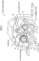
FIG. 1 is a three-dimensional schematic perspective view of a gear drive device according to an embodiment of the present invention. -
FIG. 2 is a front view of the gear drive device according to the embodiment of the present invention as seen from a gear rotation axis direction. -
FIG. 3 is a three-dimensional perspective view illustrating the positions of respective guide portions of a first gear and a second gear. -
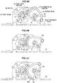
FIGS. 4A to 4C are diagrams illustrating the steps of installing the first gear and the second gear. -
FIG. 1 is a three-dimensional schematic perspective view of a gear drive device according to an embodiment of the present invention.FIG. 2 is a front view of the gear drive device according to the embodiment of the present invention as seen from a gear rotation axis direction. Below, preferred embodiments of the present invention are described in detail while referencing the drawings. - The
gear drive device 1 according to the present embodiment includes afirst gear 10 and asecond gear 20 in mesh with thefirst gear 10 to allow torque transmission. Thefirst gear 10 and/or thesecond gear 20 are a fan-type gear. Thefirst gear 10 and thesecond gear 20 includeguide portions - The
first gear 10, as illustrated inFIGS. 1 and2 is a spur gear and is made of resin, such as polyoxymethylene (POM) also called polyacetal, for example. Thefirst gear 10, as illustrated inFIG. 2 , is a fan-type gear that includes tooth portions (projecting portions of the teeth) 10a only around a predetermined range of a pitch circle PC 1. - An
attachment hole portion 11 is disposed in the rotation center of thefirst gear 10, and amotor shaft 51 of amotor 50 is attached to theattachment hole portion 11. Theattachment hole portion 11 and themating motor shaft 51 are integrally joined in a manner not allowing for rotation relative to one another. This configuration causes the rotation of themotor 50 to rotate thefirst gear 10. - The
second gear 20, as illustrated inFIGS. 1 and2 , is a spur gear and is made of resin such as polyoxymethylene (POM) also called polyacetal, for example. Thesecond gear 20, as illustrated inFIG. 2 , is a fan-type gear that includes tooth portions (projecting portions of the teeth) 20a only around a predetermined range of a pitch circle PC2. - An
attachment hole portion 21 is disposed in the rotation center of thesecond gear 20, and acentral shaft 70 projecting from anattachment base 30 is attached to theattachment hole portion 21. Theattachment hole portion 21 and thecentral shaft 70 mate together in a manner allowing for rotation. This configuration allows thesecond gear 20 to rotate about the center of the attachment hole portion 21 (central shaft 70). - The
first gear 10 and thesecond gear 20 have the same module for the tooth portions, and the distance between the central axes of thefirst gear 10 andsecond gear 20 is approximately the sum of d1/2 (half the pitch circle diameter d1) and d2/2 (half the pitch circle diameter d2), as illustrated inFIG. 2 . This configuration allows thefirst gear 10 and thesecond gear 20 to mesh, as illustrated inFIGS. 1 and2 , and transmit torque. - The
second gear 20 driven by thefirst gear 10 is provided with adrive pin 23 via which a drive target can be driven. - As illustrated in
FIG. 2 , thefirst gear 10 and thesecond gear 20 are a fan-type gear. Thus, thefirst gear 10 and thesecond gear 20 need to be installed so that their respective specific teeth are paired in the rotation direction. Because of this, thefirst gear 10 and thesecond gear 20 are provided with afirst guide portion 12 and asecond guide portion 22, respectively. Theguide portions first gear 10 and thesecond gear 20 in the gear rotation direction upon installation. -
FIG. 3 is a three-dimensional perspective view illustrating the positions of the respective guide portions (thefirst guide portion 12 and the second guide portion 22) of the first gear and the second gear. - As illustrated in
FIG. 3 , thefirst guide portion 12 of thefirst gear 10 is disposed separate from thetooth portions 10a of thefirst gear 10. In a similar manner, thesecond guide portion 22 of thesecond gear 20 is disposed separate from thetooth portions 20a of thesecond gear 20. - As illustrated in
FIG. 3 , thefirst guide portion 12 described above is disposed at a position spaced apart from thetooth portions 10a in the direction of tooth width W1. In a similar manner, thesecond guide portion 22 is disposed at a position spaced apart from thetooth portions 20a in the direction of tooth width W2. Accordingly, upon installation of thefirst gear 10 and thesecond gear 20, thefirst guide portion 12 and thesecond guide portion 22 come into contact with one another at a position spaced apart from thetooth portions - Additionally, as illustrated in
FIGS. 2 and3 , thefirst guide portion 12 protrudes from atooth tip 10b of thefirst gear 10. This configuration reliably prevents the tooth tips of thefirst gear 10 and thesecond gear 20 from coming into contact with one another upon installation. - The
attachment base 30, as illustrated inFIGS. 1 and2 , functions as the base of the unit constituted by thegear drive device 1 and supports thefirst gear 10 and thesecond gear 20 via themotor 50 and thecentral shaft 70. For example, stainless steel, treated steel, or the like is subjected to stamping to form theattachment base 30. - A
coil portion 41 of thetorsion spring 40, as illustrated inFIGS. 1 and2 , is attached to aboss portion 14 of thefirst gear 10 and applies a biasing force to thefirst gear 10 in a predetermined rotation direction (direction A). Thetorsion spring 40 is made of a spring steel, stainless steel for springs, or the like and includesarm portions coil portion 41. - As illustrated in
FIG. 1 , thearm portion 42, which is one of the arm portions of thetorsion spring 40, is locked to a lockingportion 61 of ablock member 60 fixed to theattachment base 30. Theother arm portion 43 is locked to aspring locking portion 13 which is a part of thefirst gear 10. This configuration biases thefirst gear 10 to rotate in the direction A. - The
motor 50, as illustrated inFIGS. 1 and2 , is fixed to theattachment base 30 viascrews motor shaft 51 protruding to the side on which thefirst gear 10 is located. Examples of motors that can be used for themotor 50 include a brush DC motor, a brushless DC motor, and the like. - As illustrated in
FIG. 1 , thecentral shaft 70 is inserted in anattachment hole portion 62 and aleg portion 63 is locked in anotch portion 31 of theattachment base 30, resulting in theblock member 60 being fixed to theattachment base 30. Theblock member 60 is made of resin or the like, for example. Theblock member 60 restricts movement of thesecond gear 20 in the axial direction of thecentral shaft 70, which prevents thesecond gear 20 from coming off thecentral shaft 70. Additionally, theblock member 60, as described above, is provided with the lockingportion 61 for locking thearm portion 42, which is one of the arm portions, of thetorsion spring 40. This configuration allows thefirst gear 10 to be biased via thetorsion spring 40 to rotate in the direction A from theattachment base 30 side. -
FIGS. 4A to 4C are diagrams illustrating the steps of installing the first gear and the second gear. -
FIG. 4A illustrates a state in which thefirst gear 10 and thesecond gear 20 are placed at initial positions for installation on themotor 50 attached to theattachment base 30 and thecentral shaft 70 projecting from theattachment base 30, respectively. Theattachment hole portion 11 of thefirst gear 10 is fitted on themotor shaft 51. Additionally, theattachment hole portion 21 of thesecond gear 20 is fitted on thecentral shaft 70. Note that in this state, thetorsion spring 40 has yet to be mounted. - At the initial positions prior to installation of the
first gear 10 and thesecond gear 20, as illustrated inFIG. 4A , thefirst guide portion 12 and thesecond guide portion 22 are in contact with one another. Note that the initial positions prior to installation of thefirst gear 10 and thesecond gear 20 may also be positions at which thefirst guide portion 12 and thesecond guide portion 22 are rotated opposite to the direction A and direction B illustrated inFIG. 4A , respectively, so as to be spaced apart from one another a predetermined distance. -
FIG. 4B is a diagram illustrating a state in which rotating thesecond gear 20 in the direction B in the state illustrated inFIG. 4A brings the respective specific teeth of thefirst gear 10 and thesecond gear 20 in mesh and rotates thefirst gear 10 in the direction A. In other words, in the state illustrated inFIG. 4A in which thefirst guide portion 12 and thesecond guide portion 22 are in contact with one another, the respective specific teeth portions (10a and 20a) of thefirst gear 10 and thesecond gear 20 are brought in mesh and thefirst gear 10 rotates in the direction A following the rotation of thesecond gear 20 in the direction B. -
FIG. 4C illustrates a state in which thesecond gear 20 rotates further in the direction B so that thesecond guide portion 22 comes into contact with aplate surface 30a of theattachment base 30. In other words, rotation of thefirst gear 10 and thesecond gear 20 is restricted at the positions illustrated inFIG. 4C . - As illustrated in
FIGS. 1 and2 , thetorsion spring 40 mounted to thefirst gear 10 biases thefirst gear 10 in the direction A. This makes thesecond gear 20 biased in the direction B. Accordingly, after installation in which thetorsion spring 40 is mounted to thefirst gear 10, a state in which thesecond guide portion 22 is in contact with theplate surface 30a of theattachment base 30 is the post installation state. - The
second guide portion 22 includes a positioning function to determine the initial position in the gear rotation direction of thefirst gear 10 or thesecond gear 20 after installation. Note that in another embodiment, thefirst guide portion 12 may include the positioning function to determine the initial position after installation. - A gear drive device according to embodiments of the present invention has the following effects.
- (1) The gear drive device according to the present embodiment includes the fan-type
first gear 10 andsecond gear 20. Thus, thefirst gear 10 andsecond gear 20 need to be installed so that their respective specific teeth are paired in the rotation direction. Because of this, thefirst gear 10 and thesecond gear 20 are provided with thefirst guide portion 12 and thesecond guide portion 22, respectively. Theguide portions first gear 10 and thesecond gear 20 in the gear rotation direction upon installation. This configuration allows thefirst gear 10 and thesecond gear 20 to be installed with any teeth paired and without tooth tips coming into contact. - (2) The
first guide portion 12, as illustrated inFIG. 3 , is disposed at a position spaced apart from thetooth portions 10a in the direction of tooth width W1. In a similar manner as illustrated inFIG. 3 , thesecond guide portion 22 is disposed at a position spaced apart from thetooth portions 20a in the direction of tooth width W2. Accordingly, upon installation of thefirst gear 10 and thesecond gear 20, thefirst guide portion 12 and thesecond guide portion 22 come into contact with one another at a position spaced apart from thetooth portions - (3) The
first guide portion 12 protrudes from thetooth tip 10b of thefirst gear 10. This configuration reliably prevents the tooth tips of thefirst gear 10 and thesecond gear 20 from coming into contact with one another upon installation. - (4) Accordingly, in the configuration described above, cutting of the teeth due to contact between the tooth tips of the gears upon installation can be suppressed.
- As made clear above, the invention according to the scope of the claims is not limited by the representative embodiments, modified examples, and illustrated examples according to the present invention described above. As such, it should be understood that all combinations of the features described in the embodiments, modified examples, and illustrated examples are not required parts of the means to solve the problem of the invention.
Claims (7)
- A gear drive device, comprising:a first gear; anda second gear that meshes with the first gear to allow torque transmission,wherein at least one of the first gear and the second gear comprises a fan-type gear,wherein the first gear and the second gear each comprise a guide portion, andwherein the guide portion is configured to position the first gear and the second gear in a gear rotation direction upon installation thereof.
- The gear drive device according to claim 1, wherein the guide portion is disposed separately from a tooth portion of the first gear and the second gear.
- The gear drive device according to claim 2, wherein the guide portion contacts with one another at a position spaced apart from the tooth portion in a tooth width direction.
- The gear drive device according to any one of claims 1 to 3, wherein the guide portion of at least one of the first gear and the second gear protrudes from a tooth tip.
- The gear drive device according to any one of claims 1 to 4, wherein the guide portion functions to determine an initial position in the gear rotation direction of the first gear and the second gear after the installation.
- The gear drive device according to claim 5, further comprising an attachment base,wherein the initial position is determined by contacting the guide portion with a surface of the attachment base.
- The gear drive device according to claim 6, further comprising a spring that is configured to bias the first gear or the second gear in the gear rotation direction,wherein the guide portion is contacted with the surface of the attachment base by a biasing force of the spring.
Applications Claiming Priority (1)
| Application Number | Priority Date | Filing Date | Title |
|---|---|---|---|
| JP2016058378A JP6218196B2 (en) | 2016-03-23 | 2016-03-23 | Gear drive |
Publications (2)
| Publication Number | Publication Date |
|---|---|
| EP3222880A1 true EP3222880A1 (en) | 2017-09-27 |
| EP3222880B1 EP3222880B1 (en) | 2020-07-29 |
Family
ID=58428089
Family Applications (1)
| Application Number | Title | Priority Date | Filing Date |
|---|---|---|---|
| EP17162455.4A Not-in-force EP3222880B1 (en) | 2016-03-23 | 2017-03-22 | Gear drive device |
Country Status (4)
| Country | Link |
|---|---|
| US (1) | US10012294B2 (en) |
| EP (1) | EP3222880B1 (en) |
| JP (1) | JP6218196B2 (en) |
| CN (1) | CN107448550B (en) |
Families Citing this family (1)
| Publication number | Priority date | Publication date | Assignee | Title |
|---|---|---|---|---|
| DE102018218054B4 (en) * | 2018-10-22 | 2020-10-08 | Audi Ag | Fluid power valve device and method for operating a fluid power valve device |
Citations (5)
| Publication number | Priority date | Publication date | Assignee | Title |
|---|---|---|---|---|
| US4722239A (en) * | 1984-08-01 | 1988-02-02 | U.S. Philips Corporation | Gear mechanism |
| DE102007016019B3 (en) * | 2007-04-03 | 2008-09-18 | Grammer Ag | Front wheel gear tooth system for use in vehicle, has front wheel connected with angular sensor for measuring rotational angle of wheel, where rotational angle is adjusted based on height displacement |
| JP2009002422A (en) * | 2007-06-21 | 2009-01-08 | Canon Inc | Power transmission mechanism |
| EP2302261A1 (en) * | 2009-09-25 | 2011-03-30 | Keihin Corporation | Driving force transmission mechanism |
| JP2014233452A (en) | 2013-05-31 | 2014-12-15 | 株式会社三洋物産 | Game machine |
Family Cites Families (14)
| Publication number | Priority date | Publication date | Assignee | Title |
|---|---|---|---|---|
| DE2826938A1 (en) * | 1978-06-20 | 1980-01-10 | Bernhard Mittelhaeuser | Folding wing mirror mounting - has inside edge of mirror housing formed with gear teeth meshing with fixed cam on support stalk |
| US4877185A (en) * | 1986-12-31 | 1989-10-31 | Western Industries Inc. | Oscillating sprinkler |
| US4911268A (en) * | 1988-12-28 | 1990-03-27 | Pitney Bowes Inc. | Torque or force linearizing device |
| JPH10211748A (en) * | 1997-01-30 | 1998-08-11 | Seiko Epson Corp | Platen gap adjustment device |
| US6315468B2 (en) | 1997-01-30 | 2001-11-13 | Seiko Epson Corporation | Ink jet recording apparatus with a platen gap regulator |
| EP1369564A1 (en) * | 2002-06-07 | 2003-12-10 | Siemens Aktiengesellschaft | Angular motion driving mechanism and gear wheel for use in such mechanism |
| US20080067029A1 (en) * | 2006-09-18 | 2008-03-20 | Garrick Robert D | Impact damper mechanism |
| CN202678805U (en) * | 2012-05-16 | 2013-01-16 | 江苏大全凯帆电器股份有限公司 | A three-position indicating mechanism of a drawer circuit breaker |
| JP6033696B2 (en) * | 2013-01-29 | 2016-11-30 | 株式会社東海理化電機製作所 | Tactile presentation device |
| JP2015045362A (en) * | 2013-08-28 | 2015-03-12 | 株式会社東海理化電機製作所 | Power transmission mechanism and input device equipped with the same |
| DE102014200844A1 (en) * | 2014-01-17 | 2015-07-23 | Volkswagen Aktiengesellschaft | Adjustment arrangement for a rotary valve |
| JP2016018414A (en) * | 2014-07-09 | 2016-02-01 | 株式会社東海理化電機製作所 | Input device |
| CN204136477U (en) * | 2014-09-27 | 2015-02-04 | 胡金花 | A kind of deflector roll pressure-regulating device |
| CN204871843U (en) * | 2015-09-07 | 2015-12-16 | 张军 | Cam positioner of labeller |
-
2016
- 2016-03-23 JP JP2016058378A patent/JP6218196B2/en active Active
-
2017
- 2017-03-15 US US15/459,710 patent/US10012294B2/en active Active
- 2017-03-15 CN CN201710152933.6A patent/CN107448550B/en active Active
- 2017-03-22 EP EP17162455.4A patent/EP3222880B1/en not_active Not-in-force
Patent Citations (5)
| Publication number | Priority date | Publication date | Assignee | Title |
|---|---|---|---|---|
| US4722239A (en) * | 1984-08-01 | 1988-02-02 | U.S. Philips Corporation | Gear mechanism |
| DE102007016019B3 (en) * | 2007-04-03 | 2008-09-18 | Grammer Ag | Front wheel gear tooth system for use in vehicle, has front wheel connected with angular sensor for measuring rotational angle of wheel, where rotational angle is adjusted based on height displacement |
| JP2009002422A (en) * | 2007-06-21 | 2009-01-08 | Canon Inc | Power transmission mechanism |
| EP2302261A1 (en) * | 2009-09-25 | 2011-03-30 | Keihin Corporation | Driving force transmission mechanism |
| JP2014233452A (en) | 2013-05-31 | 2014-12-15 | 株式会社三洋物産 | Game machine |
Also Published As
| Publication number | Publication date |
|---|---|
| EP3222880B1 (en) | 2020-07-29 |
| JP6218196B2 (en) | 2017-10-25 |
| US20170276218A1 (en) | 2017-09-28 |
| JP2017172666A (en) | 2017-09-28 |
| US10012294B2 (en) | 2018-07-03 |
| CN107448550A (en) | 2017-12-08 |
| CN107448550B (en) | 2020-04-17 |
Similar Documents
| Publication | Publication Date | Title |
|---|---|---|
| KR101581087B1 (en) | Geared motor | |
| WO2015113535A2 (en) | Electric motor with retainer disc and method for assembling same | |
| DE102015002562A1 (en) | Electric machine, in particular electric motor for a motor vehicle | |
| WO2010070014A1 (en) | Angle sensor | |
| US10816076B2 (en) | Plastic helical gear | |
| EP2365615A2 (en) | Rotary electrical machine | |
| EP1895277B1 (en) | Winkelkodierer mit Montagehilfe | |
| EP3300687B1 (en) | Electrically driven device | |
| US10012294B2 (en) | Gear drive device | |
| JP2010057298A (en) | Electric motor | |
| DE102020120250A1 (en) | Guide element for an electric motor | |
| JP2014502589A (en) | Roller conveyor with torque support | |
| EP3236107A1 (en) | Gear drive device | |
| JP2008109834A (en) | Brushless motor | |
| DE102010005854B4 (en) | actuator | |
| TWI682092B (en) | Cylinder lock | |
| DE102004056990B4 (en) | Electric machine, in particular brushless DC motor, and method for adjusting a sensor unit in an electric machine | |
| JP4657849B2 (en) | Fixed structure of motor with reducer of orthogonal axis type | |
| JP5053921B2 (en) | Motor and manufacturing method thereof | |
| JP2005304111A (en) | Resilient supporting structure of rotor shaft | |
| CN107450761B (en) | Operating device and method for producing same | |
| US20180062476A1 (en) | Motor and motor assembly device | |
| JP3249526B2 (en) | Metronome device | |
| US20120049670A1 (en) | Electric motor and method for its production | |
| JP4191148B2 (en) | Spiral cable device |
Legal Events
| Date | Code | Title | Description |
|---|---|---|---|
| PUAI | Public reference made under article 153(3) epc to a published international application that has entered the european phase |
Free format text: ORIGINAL CODE: 0009012 |
|
| STAA | Information on the status of an ep patent application or granted ep patent |
Free format text: STATUS: THE APPLICATION HAS BEEN PUBLISHED |
|
| AK | Designated contracting states |
Kind code of ref document: A1 Designated state(s): AL AT BE BG CH CY CZ DE DK EE ES FI FR GB GR HR HU IE IS IT LI LT LU LV MC MK MT NL NO PL PT RO RS SE SI SK SM TR |
|
| AX | Request for extension of the european patent |
Extension state: BA ME |
|
| STAA | Information on the status of an ep patent application or granted ep patent |
Free format text: STATUS: REQUEST FOR EXAMINATION WAS MADE |
|
| 17P | Request for examination filed |
Effective date: 20180327 |
|
| RBV | Designated contracting states (corrected) |
Designated state(s): AL AT BE BG CH CY CZ DE DK EE ES FI FR GB GR HR HU IE IS IT LI LT LU LV MC MK MT NL NO PL PT RO RS SE SI SK SM TR |
|
| STAA | Information on the status of an ep patent application or granted ep patent |
Free format text: STATUS: EXAMINATION IS IN PROGRESS |
|
| 17Q | First examination report despatched |
Effective date: 20180704 |
|
| GRAP | Despatch of communication of intention to grant a patent |
Free format text: ORIGINAL CODE: EPIDOSNIGR1 |
|
| STAA | Information on the status of an ep patent application or granted ep patent |
Free format text: STATUS: GRANT OF PATENT IS INTENDED |
|
| INTG | Intention to grant announced |
Effective date: 20200131 |
|
| GRAS | Grant fee paid |
Free format text: ORIGINAL CODE: EPIDOSNIGR3 |
|
| GRAA | (expected) grant |
Free format text: ORIGINAL CODE: 0009210 |
|
| STAA | Information on the status of an ep patent application or granted ep patent |
Free format text: STATUS: THE PATENT HAS BEEN GRANTED |
|
| AK | Designated contracting states |
Kind code of ref document: B1 Designated state(s): AL AT BE BG CH CY CZ DE DK EE ES FI FR GB GR HR HU IE IS IT LI LT LU LV MC MK MT NL NO PL PT RO RS SE SI SK SM TR |
|
| REG | Reference to a national code |
Ref country code: CH Ref legal event code: EP |
|
| REG | Reference to a national code |
Ref country code: AT Ref legal event code: REF Ref document number: 1296179 Country of ref document: AT Kind code of ref document: T Effective date: 20200815 |
|
| REG | Reference to a national code |
Ref country code: IE Ref legal event code: FG4D |
|
| REG | Reference to a national code |
Ref country code: DE Ref legal event code: R096 Ref document number: 602017020401 Country of ref document: DE |
|
| REG | Reference to a national code |
Ref country code: LT Ref legal event code: MG4D |
|
| REG | Reference to a national code |
Ref country code: NL Ref legal event code: MP Effective date: 20200729 |
|
| REG | Reference to a national code |
Ref country code: AT Ref legal event code: MK05 Ref document number: 1296179 Country of ref document: AT Kind code of ref document: T Effective date: 20200729 |
|
| PG25 | Lapsed in a contracting state [announced via postgrant information from national office to epo] |
Ref country code: ES Free format text: LAPSE BECAUSE OF FAILURE TO SUBMIT A TRANSLATION OF THE DESCRIPTION OR TO PAY THE FEE WITHIN THE PRESCRIBED TIME-LIMIT Effective date: 20200729 Ref country code: BG Free format text: LAPSE BECAUSE OF FAILURE TO SUBMIT A TRANSLATION OF THE DESCRIPTION OR TO PAY THE FEE WITHIN THE PRESCRIBED TIME-LIMIT Effective date: 20201029 Ref country code: SE Free format text: LAPSE BECAUSE OF FAILURE TO SUBMIT A TRANSLATION OF THE DESCRIPTION OR TO PAY THE FEE WITHIN THE PRESCRIBED TIME-LIMIT Effective date: 20200729 Ref country code: LT Free format text: LAPSE BECAUSE OF FAILURE TO SUBMIT A TRANSLATION OF THE DESCRIPTION OR TO PAY THE FEE WITHIN THE PRESCRIBED TIME-LIMIT Effective date: 20200729 Ref country code: HR Free format text: LAPSE BECAUSE OF FAILURE TO SUBMIT A TRANSLATION OF THE DESCRIPTION OR TO PAY THE FEE WITHIN THE PRESCRIBED TIME-LIMIT Effective date: 20200729 Ref country code: FI Free format text: LAPSE BECAUSE OF FAILURE TO SUBMIT A TRANSLATION OF THE DESCRIPTION OR TO PAY THE FEE WITHIN THE PRESCRIBED TIME-LIMIT Effective date: 20200729 Ref country code: GR Free format text: LAPSE BECAUSE OF FAILURE TO SUBMIT A TRANSLATION OF THE DESCRIPTION OR TO PAY THE FEE WITHIN THE PRESCRIBED TIME-LIMIT Effective date: 20201030 Ref country code: PT Free format text: LAPSE BECAUSE OF FAILURE TO SUBMIT A TRANSLATION OF THE DESCRIPTION OR TO PAY THE FEE WITHIN THE PRESCRIBED TIME-LIMIT Effective date: 20201130 Ref country code: NO Free format text: LAPSE BECAUSE OF FAILURE TO SUBMIT A TRANSLATION OF THE DESCRIPTION OR TO PAY THE FEE WITHIN THE PRESCRIBED TIME-LIMIT Effective date: 20201029 Ref country code: AT Free format text: LAPSE BECAUSE OF FAILURE TO SUBMIT A TRANSLATION OF THE DESCRIPTION OR TO PAY THE FEE WITHIN THE PRESCRIBED TIME-LIMIT Effective date: 20200729 |
|
| PG25 | Lapsed in a contracting state [announced via postgrant information from national office to epo] |
Ref country code: PL Free format text: LAPSE BECAUSE OF FAILURE TO SUBMIT A TRANSLATION OF THE DESCRIPTION OR TO PAY THE FEE WITHIN THE PRESCRIBED TIME-LIMIT Effective date: 20200729 Ref country code: RS Free format text: LAPSE BECAUSE OF FAILURE TO SUBMIT A TRANSLATION OF THE DESCRIPTION OR TO PAY THE FEE WITHIN THE PRESCRIBED TIME-LIMIT Effective date: 20200729 Ref country code: LV Free format text: LAPSE BECAUSE OF FAILURE TO SUBMIT A TRANSLATION OF THE DESCRIPTION OR TO PAY THE FEE WITHIN THE PRESCRIBED TIME-LIMIT Effective date: 20200729 Ref country code: IS Free format text: LAPSE BECAUSE OF FAILURE TO SUBMIT A TRANSLATION OF THE DESCRIPTION OR TO PAY THE FEE WITHIN THE PRESCRIBED TIME-LIMIT Effective date: 20201129 |
|
| PG25 | Lapsed in a contracting state [announced via postgrant information from national office to epo] |
Ref country code: NL Free format text: LAPSE BECAUSE OF FAILURE TO SUBMIT A TRANSLATION OF THE DESCRIPTION OR TO PAY THE FEE WITHIN THE PRESCRIBED TIME-LIMIT Effective date: 20200729 |
|
| PG25 | Lapsed in a contracting state [announced via postgrant information from national office to epo] |
Ref country code: SM Free format text: LAPSE BECAUSE OF FAILURE TO SUBMIT A TRANSLATION OF THE DESCRIPTION OR TO PAY THE FEE WITHIN THE PRESCRIBED TIME-LIMIT Effective date: 20200729 Ref country code: IT Free format text: LAPSE BECAUSE OF FAILURE TO SUBMIT A TRANSLATION OF THE DESCRIPTION OR TO PAY THE FEE WITHIN THE PRESCRIBED TIME-LIMIT Effective date: 20200729 Ref country code: EE Free format text: LAPSE BECAUSE OF FAILURE TO SUBMIT A TRANSLATION OF THE DESCRIPTION OR TO PAY THE FEE WITHIN THE PRESCRIBED TIME-LIMIT Effective date: 20200729 Ref country code: CZ Free format text: LAPSE BECAUSE OF FAILURE TO SUBMIT A TRANSLATION OF THE DESCRIPTION OR TO PAY THE FEE WITHIN THE PRESCRIBED TIME-LIMIT Effective date: 20200729 Ref country code: DK Free format text: LAPSE BECAUSE OF FAILURE TO SUBMIT A TRANSLATION OF THE DESCRIPTION OR TO PAY THE FEE WITHIN THE PRESCRIBED TIME-LIMIT Effective date: 20200729 Ref country code: RO Free format text: LAPSE BECAUSE OF FAILURE TO SUBMIT A TRANSLATION OF THE DESCRIPTION OR TO PAY THE FEE WITHIN THE PRESCRIBED TIME-LIMIT Effective date: 20200729 |
|
| REG | Reference to a national code |
Ref country code: DE Ref legal event code: R097 Ref document number: 602017020401 Country of ref document: DE |
|
| PG25 | Lapsed in a contracting state [announced via postgrant information from national office to epo] |
Ref country code: AL Free format text: LAPSE BECAUSE OF FAILURE TO SUBMIT A TRANSLATION OF THE DESCRIPTION OR TO PAY THE FEE WITHIN THE PRESCRIBED TIME-LIMIT Effective date: 20200729 |
|
| PLBE | No opposition filed within time limit |
Free format text: ORIGINAL CODE: 0009261 |
|
| STAA | Information on the status of an ep patent application or granted ep patent |
Free format text: STATUS: NO OPPOSITION FILED WITHIN TIME LIMIT |
|
| PG25 | Lapsed in a contracting state [announced via postgrant information from national office to epo] |
Ref country code: SK Free format text: LAPSE BECAUSE OF FAILURE TO SUBMIT A TRANSLATION OF THE DESCRIPTION OR TO PAY THE FEE WITHIN THE PRESCRIBED TIME-LIMIT Effective date: 20200729 |
|
| 26N | No opposition filed |
Effective date: 20210430 |
|
| PG25 | Lapsed in a contracting state [announced via postgrant information from national office to epo] |
Ref country code: SI Free format text: LAPSE BECAUSE OF FAILURE TO SUBMIT A TRANSLATION OF THE DESCRIPTION OR TO PAY THE FEE WITHIN THE PRESCRIBED TIME-LIMIT Effective date: 20200729 |
|
| PG25 | Lapsed in a contracting state [announced via postgrant information from national office to epo] |
Ref country code: MC Free format text: LAPSE BECAUSE OF FAILURE TO SUBMIT A TRANSLATION OF THE DESCRIPTION OR TO PAY THE FEE WITHIN THE PRESCRIBED TIME-LIMIT Effective date: 20200729 |
|
| REG | Reference to a national code |
Ref country code: CH Ref legal event code: PL |
|
| GBPC | Gb: european patent ceased through non-payment of renewal fee |
Effective date: 20210322 |
|
| REG | Reference to a national code |
Ref country code: BE Ref legal event code: MM Effective date: 20210331 |
|
| PG25 | Lapsed in a contracting state [announced via postgrant information from national office to epo] |
Ref country code: LU Free format text: LAPSE BECAUSE OF NON-PAYMENT OF DUE FEES Effective date: 20210322 Ref country code: LI Free format text: LAPSE BECAUSE OF NON-PAYMENT OF DUE FEES Effective date: 20210331 Ref country code: CH Free format text: LAPSE BECAUSE OF NON-PAYMENT OF DUE FEES Effective date: 20210331 Ref country code: FR Free format text: LAPSE BECAUSE OF NON-PAYMENT OF DUE FEES Effective date: 20210331 Ref country code: IE Free format text: LAPSE BECAUSE OF NON-PAYMENT OF DUE FEES Effective date: 20210322 Ref country code: GB Free format text: LAPSE BECAUSE OF NON-PAYMENT OF DUE FEES Effective date: 20210322 |
|
| PG25 | Lapsed in a contracting state [announced via postgrant information from national office to epo] |
Ref country code: BE Free format text: LAPSE BECAUSE OF NON-PAYMENT OF DUE FEES Effective date: 20210331 |
|
| PG25 | Lapsed in a contracting state [announced via postgrant information from national office to epo] |
Ref country code: HU Free format text: LAPSE BECAUSE OF FAILURE TO SUBMIT A TRANSLATION OF THE DESCRIPTION OR TO PAY THE FEE WITHIN THE PRESCRIBED TIME-LIMIT; INVALID AB INITIO Effective date: 20170322 |
|
| PGFP | Annual fee paid to national office [announced via postgrant information from national office to epo] |
Ref country code: DE Payment date: 20230131 Year of fee payment: 7 |
|
| PG25 | Lapsed in a contracting state [announced via postgrant information from national office to epo] |
Ref country code: CY Free format text: LAPSE BECAUSE OF FAILURE TO SUBMIT A TRANSLATION OF THE DESCRIPTION OR TO PAY THE FEE WITHIN THE PRESCRIBED TIME-LIMIT Effective date: 20200729 |
|
| PG25 | Lapsed in a contracting state [announced via postgrant information from national office to epo] |
Ref country code: MK Free format text: LAPSE BECAUSE OF FAILURE TO SUBMIT A TRANSLATION OF THE DESCRIPTION OR TO PAY THE FEE WITHIN THE PRESCRIBED TIME-LIMIT Effective date: 20200729 |
|
| PG25 | Lapsed in a contracting state [announced via postgrant information from national office to epo] |
Ref country code: TR Free format text: LAPSE BECAUSE OF FAILURE TO SUBMIT A TRANSLATION OF THE DESCRIPTION OR TO PAY THE FEE WITHIN THE PRESCRIBED TIME-LIMIT Effective date: 20200729 |
|
| PG25 | Lapsed in a contracting state [announced via postgrant information from national office to epo] |
Ref country code: MT Free format text: LAPSE BECAUSE OF FAILURE TO SUBMIT A TRANSLATION OF THE DESCRIPTION OR TO PAY THE FEE WITHIN THE PRESCRIBED TIME-LIMIT Effective date: 20200729 |
|
| REG | Reference to a national code |
Ref country code: DE Ref legal event code: R119 Ref document number: 602017020401 Country of ref document: DE |
|
| PG25 | Lapsed in a contracting state [announced via postgrant information from national office to epo] |
Ref country code: DE Free format text: LAPSE BECAUSE OF NON-PAYMENT OF DUE FEES Effective date: 20241001 |
|
| PG25 | Lapsed in a contracting state [announced via postgrant information from national office to epo] |
Ref country code: DE Free format text: LAPSE BECAUSE OF NON-PAYMENT OF DUE FEES Effective date: 20241001 |