EP3222829A1 - Oil separation device, in particular for a crankcase ventilating system of a combustion engine - Google Patents
Oil separation device, in particular for a crankcase ventilating system of a combustion engine Download PDFInfo
- Publication number
- EP3222829A1 EP3222829A1 EP17166276.0A EP17166276A EP3222829A1 EP 3222829 A1 EP3222829 A1 EP 3222829A1 EP 17166276 A EP17166276 A EP 17166276A EP 3222829 A1 EP3222829 A1 EP 3222829A1
- Authority
- EP
- European Patent Office
- Prior art keywords
- oil separation
- oil
- hollow body
- flow
- gas flow
- Prior art date
- Legal status (The legal status is an assumption and is not a legal conclusion. Google has not performed a legal analysis and makes no representation as to the accuracy of the status listed.)
- Withdrawn
Links
Images


Classifications
-
- F—MECHANICAL ENGINEERING; LIGHTING; HEATING; WEAPONS; BLASTING
- F01—MACHINES OR ENGINES IN GENERAL; ENGINE PLANTS IN GENERAL; STEAM ENGINES
- F01M—LUBRICATING OF MACHINES OR ENGINES IN GENERAL; LUBRICATING INTERNAL COMBUSTION ENGINES; CRANKCASE VENTILATING
- F01M13/00—Crankcase ventilating or breathing
- F01M13/04—Crankcase ventilating or breathing having means for purifying air before leaving crankcase, e.g. removing oil
-
- F—MECHANICAL ENGINEERING; LIGHTING; HEATING; WEAPONS; BLASTING
- F01—MACHINES OR ENGINES IN GENERAL; ENGINE PLANTS IN GENERAL; STEAM ENGINES
- F01L—CYCLICALLY OPERATING VALVES FOR MACHINES OR ENGINES
- F01L1/00—Valve-gear or valve arrangements, e.g. lift-valve gear
- F01L1/02—Valve drive
- F01L1/04—Valve drive by means of cams, camshafts, cam discs, eccentrics or the like
- F01L1/047—Camshafts
- F01L2001/0475—Hollow camshafts
-
- F—MECHANICAL ENGINEERING; LIGHTING; HEATING; WEAPONS; BLASTING
- F01—MACHINES OR ENGINES IN GENERAL; ENGINE PLANTS IN GENERAL; STEAM ENGINES
- F01M—LUBRICATING OF MACHINES OR ENGINES IN GENERAL; LUBRICATING INTERNAL COMBUSTION ENGINES; CRANKCASE VENTILATING
- F01M13/00—Crankcase ventilating or breathing
- F01M13/04—Crankcase ventilating or breathing having means for purifying air before leaving crankcase, e.g. removing oil
- F01M2013/0422—Separating oil and gas with a centrifuge device
-
- F—MECHANICAL ENGINEERING; LIGHTING; HEATING; WEAPONS; BLASTING
- F01—MACHINES OR ENGINES IN GENERAL; ENGINE PLANTS IN GENERAL; STEAM ENGINES
- F01M—LUBRICATING OF MACHINES OR ENGINES IN GENERAL; LUBRICATING INTERNAL COMBUSTION ENGINES; CRANKCASE VENTILATING
- F01M13/00—Crankcase ventilating or breathing
- F01M13/04—Crankcase ventilating or breathing having means for purifying air before leaving crankcase, e.g. removing oil
- F01M2013/0433—Crankcase ventilating or breathing having means for purifying air before leaving crankcase, e.g. removing oil with a deflection device, e.g. screen
-
- F—MECHANICAL ENGINEERING; LIGHTING; HEATING; WEAPONS; BLASTING
- F01—MACHINES OR ENGINES IN GENERAL; ENGINE PLANTS IN GENERAL; STEAM ENGINES
- F01M—LUBRICATING OF MACHINES OR ENGINES IN GENERAL; LUBRICATING INTERNAL COMBUSTION ENGINES; CRANKCASE VENTILATING
- F01M13/00—Crankcase ventilating or breathing
- F01M13/04—Crankcase ventilating or breathing having means for purifying air before leaving crankcase, e.g. removing oil
- F01M2013/0438—Crankcase ventilating or breathing having means for purifying air before leaving crankcase, e.g. removing oil with a filter
Definitions
- the present invention relates to an oil separation device, in particular for a crankcase ventilation of an internal combustion engine, having a hollow body axially extending in a longitudinal axis, which is flowed through by an oil-laden gas stream, wherein in the hollow body provided with an axial passage oil separation body is introduced by the gas flow can be flowed on.
- blow-by gas In internal combustion engines and piston compressors leakage losses are observed in practice, which are due to an incomplete seal, for example, the piston-cylinder or the valve guides in the cylinder head. Leakage losses are referred to as blow-by gas and contain a significant amount of oil. With reference to internal combustion engines, it is therefore customary to conduct the blowby gas accumulating during operation of the internal combustion engine back into the intake tract of the internal combustion engine. On the one hand to minimize the loss of oil by the blowby gas and on the other hand to ensure optimum combustion and a minimum environmental impact, it is known to supply the blowby gas to an oil separator and to lead the separated oil back into the oil circuit. There is a desire to design appropriate oil separation systems as simple as possible but still reliable and efficient.
- Another aspect of improving oil separation devices relates to a minimum flow resistance experienced by the gas flow as it flows through the oil separator.
- a high separation efficiency is required to minimize the entry of residual oil into the charge air tract, in particular to prevent oiling of air mass meters and turbochargers.
- the DE 10 2009 012 400 A1 shows an oil separator, which is suitable for crankcase ventilation of an internal combustion engine.
- the ⁇ labscheide realized a hollow body, which may be formed for example by a portion of a camshaft, or the hollow body is tubular and integrated in a cylinder head cover of an internal combustion engine.
- a swirl generator is arranged, and the hollow body has an end-side feed opening for introducing the Gas stream and a discharge opening for discharging the gas stream.
- the gas stream introduced into the hollow body may carry oil in the form of oil mist or spray droplets which are to be removed from the gas stream by the oil separation device.
- the cavity further comprises a discharge opening for the discharge of separated oil, which is carried out separately from the discharge of the liberated from the oil gas stream.
- the oil separator shown uses a swirl effect, which is particularly advantageous when the oil separator is incorporated in a rotating camshaft, which forms the hollow body of the oil separator.
- a swirl generator is provided with a plurality of spirally formed flow channels in the hollow body, through which a swirl is introduced into the oil-laden gas stream. Due to the concomitant change in the flow direction of the gas stream entrained oil droplets are deposited in the gas flow to the inner wall of the hollow body, and by the flow of the hollow body in the longitudinal direction, the oil droplets reach the outer region of the ⁇ labscheideringes, through which the gas flow in the central region of the hollow body of the oil flow in the wall portion of the hollow body is separated.
- the oil can be separated by the discharge opening for the oil from the discharge opening of the purified gas stream, which is subsequently fed to the intake tract of the internal combustion engine or, for example, also to a reciprocating compressor.
- this may be formed of a porous plastic or of a sintered material, wherein plastic or metal braids are advantageously used.
- Such braids form a plurality of cavities and labyrinths, whereby the separation of the oil from the gas stream is further supported.
- the swirl conveys the oil droplets radially outward with respect to the longitudinal axis of the hollow body, and the gas stream is passed through the central passage in the oil separation ring.
- the object of the invention is the development of a ⁇ labscheide worn especially for the crankcase ventilation of an internal combustion engine, which has a high separation efficiency of oil made possible from a gas stream and which is further developed in particular such that the lowest possible flow resistance of the gas stream is formed by the hollow body.
- the invention includes the technical teaching that in the region of the passage of the ⁇ labscheide endeavors a deflecting body is introduced into the hollow body, which is flowed by the gas stream substantially from the direction of the longitudinal axis with the gas stream and through which the gas flow radially outward against the inside of the ⁇ labscheide endeavors is distractible.
- the deflection body is arranged in the area of the passage of the oil separation body in operative influence with an intermediate element, wherein the intermediate element has radial gaps through which the gas flow reaches an inner side of the oil separation body.
- the invention is based on the idea of directing the oil-laden gas stream on the inside against the advantageously tubular or sleeve-shaped oil separation body.
- the oil from the gas stream can be deposited on the ⁇ labscheide endeavor from the gas stream, and the gas stream can pass through the oil separator body through the example central, axial passage cleaned of the oil, the separated oil between the outside of the ⁇ labscheide endeavors and the inner wall of the tubular body can be removed , Consequently, the ⁇ labscheide endeavor forms a barrier between the separated oil and the gas stream in the further course of the gas flow, wherein the oil can be removed after passing through the ⁇ labscheide endeavors from the hollow body and the oil circuit of the internal combustion engine can be fed again.
- the purified gas stream can be led out of the hollow body and fed to the charge air tract of the internal combustion engine.
- the radial gaps can already be separated from one another by fan-like lamellae which, in addition to the deflection body, already upstream of the deflection body effect a deflection of the gas flow in the direction of the inside of the oil separation body.
- the deflection of the gas stream is carried out in principle under application of a radial flow component, which superimposes the axial flow component of the gas stream in the direction of the longitudinal axis of the hollow body.
- the intermediate element or the holding body forms a kind of basket, which consists of openings for forming the radial gaps, and the basket-like intermediate element opens into the deflecting body, wherein the deflecting body and the intermediate element can be integrally formed, for example, from a plastic component.
- the oil separation body may extend approximately rotationally symmetrically about the longitudinal axis of the hollow body, and the oil separation body may be introduced into the hollow body such that substantially all of the gas flow passes through the passage in the oil separation body.
- the deflecting body can advantageously be introduced centrally in the passage of the oil separator body, and this can also extend rotationally symmetrically about the longitudinal axis. It is particularly advantageous if the deflecting viewed in the downstream, ie lying in the direction of flow, rear third of the ⁇ labscheide endeavors, whereby the gas flow is deflected so that it is directed substantially over the entire length of the ⁇ labscheide endeavors against the inside.
- the deflection body may comprise an outer diameter which is determined so that the purified gas stream can flow between the inner diameter of the ⁇ labscheide stresses and the outer diameter of the deflecting low pressure loss.
- the indication of the arrangement or orientation formed downstream in the sense of the present invention, represents only a directional indication which describes a direction which is oriented in or with a possible gas flow direction.
- the deflecting body and in particular the ⁇ labscheide endeavor be rotationally symmetrical, wherein the deflecting body may have a lying in the longitudinal axis flow tip or deflecting syringe with a preferably downstream hyperbola growing Umlenkkontur.
- the hyperbolic deflection contour results in a rotational body which forms a circumferential flow throat, so that the deflection of the flow takes place comparatively slowly in order to avoid that the oil entrained in the gas flow is already deposited on the surface of the deflection body.
- the deflection of the gas flow through the deflection body against the inside of the oil separation body takes place in such a way that the gas flow acts on the inside of the oil separation body approximately vertically in order to achieve a particular impactor effect. Due to the impactor effect, there is a strong subsequent deflection of the gas flow, which can not follow the mass drops of oil, and be absorbed by the oil separator body.
- the oil in the gas stream can be present in the form of oil mist or drops of oil that can pass through the oil separation body to continue this outside of the ⁇ labscheide emotionss between the ⁇ labscheide redesign and the inside of the hollow body downstream of the purified gas stream.
- the oil separation body is elongated in the direction of the longitudinal axis.
- the oil separation body is funnel-shaped in the direction of the longitudinal axis, wherein the funnel shape is aligned open against the flow direction of the gas stream. This has the effect that the gas flow through the deflection body does not have to be deflected, for example, by 90 °, as would be necessary in order to allow the gas flow to impinge approximately perpendicular to the inside of a hollow cylinder body.
- an inlet funnel is arranged upstream of the passage of the ⁇ labscheide endeavors upstream, through which the gas stream is accelerated into the passage of the ⁇ labscheide endeavors inside.
- the arrangement of the inlet funnel is achieved, in particular, that the gas stream laden with oil does not already impinge against the oil separation body on the front side.
- the gas stream is pre-accelerated by the inlet funnel in order to have a higher speed even before deflection through the deflecting body and through the radial gaps in the holding body. Subsequently, the gas stream can be further accelerated, since there is a further flow constriction through the radial gaps against the inside of the ⁇ labscheide emotionss.
- an opening funnel may be introduced in the hollow body, which forms a diffuser.
- the opening funnel is open in the outflow direction, that is, the opening funnel has a larger inner diameter with increasing distance from the ⁇ labscheide emotionss and can grow up to the inner diameter of the hollow body.
- the arrangement of the diffuser behind the ⁇ labscheide redesign can lead to a further reduction of the pressure loss of the gas flow in the opening funnel, whereby the flow resistance of the gas stream is further reduced when flowing through the ⁇ labscheide Anlagen.
- the inlet funnel for accelerating the gas flow can, for example, pass over in one piece into the holding body with the radial gaps, wherein the opening funnel on the side of the oil separation body can adjoin it.
- the smallest diameter of the opening funnel can correspond to the smallest diameter of the funnel-shaped oil separator body.
- the inlet funnel can protrude at least in the transition into the holding body in the funnel-shaped designed ⁇ labscheidelik, wherein the deflection in the Region and in particular can be arranged just before the region of the smallest flow cross-section, which is formed by the transition of the ⁇ labscheide emotionss in the opening funnel.
- the ⁇ labscheide endeavor may be at least partially formed of a nonwoven fabric.
- Other materials for forming the ⁇ labscheide endeavors may be porous plastics or sintered materials, with material braids of plastic or metal can be advantageously used.
- the ⁇ labscheide endeavor can be formed of a material that does not scoffed by the introduction of oil and other particles, in particular impurities, and the oil can pass through the material of the ⁇ labscheide endeavors, for example, to leave the ⁇ labscheide endeavor on the downstream side.
- the oil separation body and in particular the nonwoven fabric may have a gas permeability, which is determined such that the gas flow partially flows through the oil separation body.
- a gas permeability which is determined such that the gas flow partially flows through the oil separation body.
- a first part of the gas flow is deflected by utilizing an impactor on the inside of the ⁇ labscheide endeavors to finally leave the ⁇ labscheide endeavor through the passage.
- Another part of the gas stream can pass through the material of the ⁇ labscheide endeavors, and be continued on the outside of the opening funnel, in particular in the radial gap between the opening funnel and the inside of the hollow body, together with the separated oil.
- the radial gap formed between the outer side of the opening funnel and the inside of the hollow body thereby allows a guidance of the gas flow in such a way that the oil is separated from the gas flow by the enlarged wall contact in order likewise to achieve a cleaning effect.
- the oil is in droplet shape and can walk along the outside of the opening funnel or on the inside of the hollow body, to be finally fed to a separation opening.
- the hollow body may be formed by at least a portion of a camshaft of an internal combustion engine or the hollow body is formed component-uniformly with a cylinder head cover of an internal combustion engine.
- this rotates during operation of the internal combustion engine, so that the deflection of the gas stream is supported radially outward by the rotation of the hollow body.
- the deflecting body, the holding body, the inlet funnel and the opening funnel and in particular the ⁇ labscheide endeavor can co-rotate with the hollow body, so that a swirl is introduced into the gas stream, which promotes ejection of the oil to the outside.
- a disk-shaped oil separation ring may be disposed in front of the elongated oil separation body, wherein according to a still further embodiment, the disk-shaped oil separation ring may be preceded by a flow control body having a downstream growing flow contour.
- the flow guide body extends rotationally symmetrically about the longitudinal axis 10 of the hollow body and is held against the inside of the hollow body via corresponding retaining ribs. It is also conceivable within the scope of the invention that the oil separation ring has a rear-side support ring, against which the oil separation ring is supported.
- the oil separation ring is formed from a nonwoven fabric and forms a first separation stage.
- the oil separation device can identify two, for example, a nonwoven comprehensive oil separation body, which can be flowed through in the flow path of the gas flow in a row.
- the ⁇ labscheidering can, as well as the downstream Haupt ⁇ labscheide redesign, acted on a weak gas flow, for example, only superficially so that the gas stream does not completely flow through the nonwoven fabric.
- the gas stream passes through the ⁇ labscheidering through a central opening. If the gas flow is stronger, it can flow through the oil separation ring.
- the oil can be separated from the gas flow in such a way that it drains into the hollow body in droplet form on the inside.
- the impact of the gas stream on the oil separation ring of nonwoven fabric advantageously produces an impactor effect, so that droplets of the oil are already deposited by the impactor effect on the oil separation ring and travel downstream through appropriate recesses between the support ring and the inside of the hollow body on the inside, to then, for example, in To get a separation opening for leading out the oil from the hollow body.
- the deflecting body does not have to be rotationally symmetrical, and this deflecting body can also be elongated in a transverse direction.
- the ⁇ labscheideSh need not be rotationally symmetrical and this may also have a flat, elongated in a transverse direction extension.
- the deflecting body may have a transverse flow edge as an alternative to a flow peak.
- the oil separation body is thus elongated and in particular funnel-shaped in the direction of the longitudinal axis, wherein the funnel shape is designed to be open against the flow direction of the gas flow.
- the tubular oil separation body can again be made of a non-woven material and seat with a substantially constant outer diameter in a first section of the hollow body, which has a smaller diameter, so that no or only a very little between the ⁇ labscheide endeavor and the inside of the hollow body small radial circumferential gap is present.
- the inside of the hollow body forms a baffle surface for a gas stream which migrates through the oil separation body and for oil present in the latter at least in the front region on the flow side.
- the hollow body Downstream, can be designed with a second section with a larger diameter or with at least one lateral widening, so that the inside of the hollow body does not bear against the outside of the oil separation body and forms no baffle surface, whereby in this partial area, a flow through the ⁇ labscheide stresses with the gas stream can be improved.
- the abovementioned variants of the oil separation device are designed such that the gas flow is deflected only radially outward or partially inwards again, without a swirl or a flow component being introduced into the gas flow which would or would lead around the longitudinal axis of the oil separation device ,
- the swirl-free guidance of the gas flow through the oil separation device is based in particular on the design of the deflecting body as a rotational body or as a flat body in a transverse direction, which limits the deflection of the gas flow to radial and axial flow components.
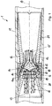
- the FIGS. 1 and 2 show in a respective sectional view of a ⁇ labscheide worn 1 with the features of the present invention.
- the oil separation device 1 has a hollow body 11 which extends along a longitudinal axis 10.
- the hollow body 11 may be formed for example by a portion of a camshaft which forms the hollow body 11 as a tubular support shaft.
- the hollow body 11 may be integrated in a cylinder head cover of an internal combustion engine. In this case, the hollow body 11 is executed according to the embodiment shown about the longitudinal axis 10 rotationally symmetrical.
- a gas stream 13 loaded with oil 12 can be introduced into the hollow body 11, and on the side of the gas inlet there is an inlet funnel 20, which reaches up to the inside of the hollow body 11.
- the gas stream 13 is thus completely introduced into the inlet funnel 20, whereby the gas stream 13 accelerates in the direction of the longitudinal axis 10.
- Adjoining the inlet funnel 20 is a holding body 18, and downstream of the holding body 18 there is a deflecting body 15 with a flow tip 16 pointing counter to the flow direction of the gas flow 13, which lies in the longitudinal axis 10.
- the deflecting body 15 extends rotationally symmetrically about the longitudinal axis 10, and the flow peak 16 is adjoined by a Umlenkkontur 17, which has an increasing diameter downstream, the increase in diameter exemplifies a hyperbolic Umlenkkontur 17 forms.
- the gas stream 13 accelerated through the inlet funnel 20 strikes the deflection body 15 with the deflection contour 17 and is deflected radially outward.
- an oil separation body 14 which is funnel-shaped, and the funnel shape opens opposite to the direction of the gas stream 13.
- the oil separation body 14 is located along the longitudinal axis 10 in such an axial Position, so that the deflecting body 15 is seated approximately in the rear third in ⁇ labscheide endeavor 14. Upstream adjoins the deflecting body 15 of the holding body 18, which is designed with radial gaps 19.
- the impinging on the deflecting body 15 gas stream 13 is passed through the radially outward deflection by the Umlenkkontur 17 through the radial column 19 of the holding body 18, and by the radial deflection of the gas stream 13, this strikes the inner side 14 a of the ⁇ labscheide emotionss 14, the off a nonwoven fabric is formed.
- An opening funnel 21 connects to the oil separation body 14, which acts as a diffuser and by which the pressure loss is minimized when flowing through the oil separation device 1 with the gas stream 13.
- FIGS. 1 and 2 show a separation of the oil 12 through the ⁇ labscheide Sciences 14, such that the oil 12 is discharged in the radial gap between the outside of the opening hopper 21 and the inside of the hollow body 11.
- the oil 12 is shown by way of example in drop form entrained with the gas stream 13, and the oil 12 may similarly be in the form of oil mist or spray oil.
- the oil 12 may be present in the gas stream 13 foreign particles in particulate form, which can also be separated by the oil separator 1 from the gas stream 13.
- FIG. 1 shows a flow through the oil separator 1 with a weaker and loaded with oil 12 gas stream 13.
- the gas stream 13 is through the Inlet hopper 20 accelerates and is deflected by the deflecting body 15 such that the gas stream 13 passes through the radial gaps 19 in the holding body 18. Subsequently, the gas flow 13 impinges on the inner side 14 a of the ⁇ labscheideMechs 14, whereby an impactor effect is achieved.
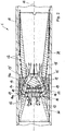
- FIG. 2 shows the ⁇ labscheide recognized 1 with a stronger gas flow 13, which enters the inlet hopper 20 loaded with oil 12.
- the gas flow 13 is deflected by the deflecting body 15 through the radial gaps 19 in the holding body 18 against the inner side 14 a of the ⁇ labscheideSchs 14, and through the stronger formation of the gas stream 13 undergoes a portion of the gas stream 13 has an impactor effect and is on the inner side 14 a of the ⁇ labscheide endeavors 14 only deflected, which is accompanied by a deposition of the teardrop-shaped oil 12.
- Another part of the gas stream 13 flows through the ⁇ labscheide endeavor 14 and exits together with the oil 12 on the outer side 14b of the ⁇ labscheide emotionss 14 again.
- the portion of the gas stream 13 flowing through the oil separation body 14 runs downstream between the inner wall of the hollow body 11 and the outer side of the opening funnel 21, whereby a separation of the gas flow 13 'from the oil 12 is also maintained in the outer region of the opening funnel. Subsequently, this purified gas stream 13 'can be recombined outside the opening funnel 21 with the purified gas stream 13' within the opening funnel 21.
- the oil 12 can be discharged in a manner not shown in detail by separating openings from the hollow body 11 and the oil circuit of the internal combustion engine are fed again.
- the purified gas stream 13 'can be supplied to the charge air tract of the internal combustion engine.
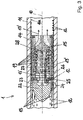
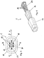
- FIG. 3 shows a further embodiment of a ⁇ labscheide driving 1, which is introduced in a hollow body 11.
- the ⁇ labscheide driving 1 has a flow guide 22, which is flown by a gas stream 13 which is loaded with droplets of oil 12.
- the flow guide 22 extends rotationally symmetrically about the longitudinal axis 10 of the hollow body 11 and is held against the inner side 11 a of the hollow body 11 via corresponding retaining ribs 23, of which a retaining rib 23 is shown on the upper side in section.
- a flow cross-sectional area 24 is formed which, regardless of the holding ribs 23, is formed essentially completely around the flow guide body 22.
- the gas stream 13 is accelerated into the flow cross-sectional area 24 by the flow guide body 22, and the accelerated gas stream 13 then strikes an oil separation ring 25, which is connected upstream of a subsequent further oil separation body 14.
- the oil separation ring 25 has a rear side support ring 26, against which the oil separation ring 25 is supported, wherein the oil separation ring 25 is formed of a nonwoven fabric and forms a first separation stage.
- the impact of the gas stream 13 on the oil separation ring 25 made of nonwoven fabric results in an impactor effect, so that droplets of the oil 12 are already deposited by the impactor effect on the oil separation ring 25.
- the separated oil 12 can migrate downstream through corresponding recesses between the carrier ring 26 and the inner side 11 a of the hollow body 11 on the inner side 11 a, in order subsequently to pass into a separation opening (not shown) for removing the oil 12 from the hollow body 11.
- the prepurified gas stream 13 then passes via an intermediate element 27 in operative influence with the deflection body 15, and the gas flow 13 'is deflected by the deflection body 15 against the oil separation body 14.
- the intermediate element 27 has radial gaps 19, through which the gas flow 13 'reaches the inside of the tubular or sleeve-shaped further oil separation body 14.
- the deflection of the gas flow 13 'radially outwards takes place through the deflecting body 15, which has a deflecting tip 28 on the front side, and the deflecting tip 28 follows an approximately hyperbolic body shape of the deflecting body 15 which extends rotationally symmetrically about the longitudinal axis 10 and which with the intermediate element 27 is formed in one piece.
- the further ⁇ labscheide endeavor 14 may also comprise a nonwoven fabric, and the pre-cleaned gas stream 13 may flow only against the inside of the ⁇ labscheide endeavors 14 or even flow through this even with at least a partial gas flow.
- the separated oil 12 can then be removed via a ⁇ labriosö réelle not shown.
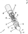
- FIG. 4 shows an exploded view of parts of the oil separator 1 according to the embodiment in FIG. 3 , wherein the hollow body 11 is not shown for clarity.
- the oil separation device 1 is flown from the arrow direction shown with the gas stream 13 and with this entrained oil 12, so that first the flow guide 22 comes into contact with the gas stream 13 and the droplets of oil 12 shown by way of example.
- the oil separation ring 25 connects, which is held by a support ring 26 back.
- the flow guide 22 can be clipped with simultaneous fixation of the oil separation ring 25 on the support ring 20, to which the holding ribs 23 are formed as snap hooks.
- the support ring 26 is exemplified in one piece with the intermediate member 27, and the intermediate member 27 has extending in the flow direction retaining walls 29, through which the further oil separation 14 can be held against the inner wall of the hollow body not shown in detail.
- a distance between the radial gaps 19 in the intermediate element 27 and the ⁇ labscheide endeavor 14 is maintained, so that the inside of the ⁇ labscheide endeavors 14 can be flowed through the gas stream 13.
- the nonwoven fabric of the oil separation body 14 need not necessarily contact the inner wall of the hollow body 11, but a gap between the outer peripheral surface of the nonwoven fabric and the inner peripheral surface of the hollow body 11 may be given to promote drainage of oil droplets.
- FIG. 5 shows a plan view of a further embodiment of an oil separator 1 from the direction of the longitudinal axis 10, wherein the oil separator 1 is not rotationally symmetrical and has a formed in a transverse direction Y elongated and thus flat extent. Visible in the plan view is also flat formed hollow body 11, in which a further embodiment of an intermediate element 27 is inserted, are introduced into the radial column 19, through which the gas flow can flow.
- the no flow peak as in FIG. 3 has, but by the elongate-flat design, the deflecting body 15 has a longitudinal flow edge 31 in the transverse direction Y.
- FIG. 6 shows a partial exploded view of the oil separator 1 according to the embodiment FIG. 5 are introduced into the radial gap 19 with the flat formed hollow body 11, the flat trained oil separator 14 and the intermediate member 27 through which the gas flow can pass and the oil separation body 14 can act on from the inside.
- FIG. 7 shows a cross-sectional view of the oil separator 1 according to the embodiment FIG. 5 in the section plane A - A and FIG. 8 shows a cross-sectional view of the oil separator 1 according to the embodiment FIG. 5 in the section plane B - B.
- the embodiment of the flat oil separator 1 has a structure and a function, as this or this already in connection with the embodiment of FIGS. 1 and 2 described above.
- a loaded with oil 12 gas stream 13 can be initiated.
- the gas stream 13 flows into the intermediate element 27, which is seated in the oil separation body 14 and forms on the front side essentially an inlet funnel 20, as in connection with FIGS FIGS. 1 and 2 described above.
- a deflecting body 15 is introduced, through which the gas stream 13 is passed through radial gaps 19 on the inside of the oil separator 14.
- the ⁇ labscheide redesign 14 is funnel-shaped, and the funnel shape opens against the direction of the gas stream 13 and tapers downstream.
- the oil separation body 14 is located along the longitudinal axis 10 in an axial position in front of the deflecting body 15, so that it is behind the ⁇ labscheidelik 14 and upstream of the diverting body 15, the gas stream 13 is passed through this through the radial gaps 19 on or through the ⁇ labscheideoasa 14.
- the separation of the oil 12 takes place for a weak and for a strong flow of the gas stream 13 as in connection with the FIGS. 1 and 2 already described.
- FIG. 7 and FIG. 8 show that the radial deflection of the gas stream 13 loaded with oil 12 takes place even in a non-rotationally symmetric deflecting body 15 in the same manner without swirling as in a rotationally symmetric deflecting body 15, because the gas stream 13 experiences no twist in the flow through the oil separator 1.
- the flat design of Oil separation device 1 with an extension in a transverse direction Y can for example be adapted to an installation situation of the device.
- the oil 12 is separated from the gas flow 13 either by an impactor effect upon impact and rebounding or by a filter action with a flow through the oil separation body 14.
- FIG. 9 shows a modified embodiment with a ⁇ labscheide sensory 1, which is constructed of a separately designed inlet funnel 20, in which the gas stream 12 loaded with oil 12 flows and to which an intermediate element 27 integrally connects.
- the intermediate element 27 is designed in the manner of a basket and has radial gaps 19 through which the gas flow 13 flows and flows against the oil separation body 14 on the inside. Depending on the flow velocity, the gas stream 13 can then impinge on or pass through only the inner surface of the oil separation body 14 until the gas stream 13 'cleaned by the oil 12 leaves the oil separation device 1 again.
- a deflecting body 15 is internally provided in the intermediate element 27, which is flowed by the gas flow 13 from the direction of the longitudinal axis 10 and by the gas flow 13 is deflected radially outwardly to flow through the radial gaps 19.
- the tubular ⁇ labscheide endeavor 14 is made of a non-woven material and is seated with a substantially constant outer diameter in a portion 11 'of the hollow body 11, which has a smaller diameter, so that between the ⁇ labscheide endeavor 14 and the inside of the hollow body 11 no or only a very small radially circumferential gap is present.
- the inside of the hollow body 11 forms a baffle surface for a gas flow through the oil separation body 14 13 and for existing in this oil 12th
Abstract
Die vorliegende Erfindung betrifft eine Ölabscheideeinrichtung (1), insbesondere für eine Kurbelgehäuseentlüftung einer Brennkraftmaschine, mit einem sich in einer Längsachse (10) axial erstreckenden Hohlkörper (11), der von einem mit Öl (12) beladenen Gasstrom (13) durchströmbar ist, wobei im Hohlkörper (11) ein mit einem axialen Durchgang versehener Ölabscheidekörper (14) eingebracht ist, der vom Gasstrom (12) anströmbar ist. Erfindungsgemäß ist im Bereich des Durchgangs des Ölabscheidekörpers (14) ein Umlenkkörper (15) in den Hohlkörper (11) eingebracht, der vom Gasstrom (13) im Wesentlichen aus Richtung der Längsachse (10) mit dem Gasstrom (13) anströmbar ist und durch den der Gasstrom (13) radial nach außen gegen die Innenseite (14a) des Ölabscheidekörpers (14) ablenkbar ist. Der Umlenkkörper (15) ist im Bereich des Durchgangs des Ölabscheidekörpers (14) in Wirkeinfluss mit einem Zwischenelement (27) angeordnet, wobei das Zwischenelement (27) Radialspalte (19) aufweist, durch die der Gasstrom (13) gegen eine Innenseite des Ölabscheidekörpers (14) gelangt.The invention relates to an oil separation device (1), in particular for crankcase ventilation of an internal combustion engine, having a hollow body (11) extending axially in a longitudinal axis (10) and permeable by a gas flow (13) laden with oil (12) in the hollow body (11) provided with an axial passage Ölabscheidekörper (14) is introduced, which is flowed by the gas stream (12). According to the invention, in the region of the passage of the oil separation body (14), a deflection body (15) is introduced into the hollow body (11), which can be flowed by the gas flow (13) substantially from the direction of the longitudinal axis (10) to the gas flow (13) and through the the gas flow (13) can be deflected radially outward against the inside (14a) of the oil separation body (14). The deflection body (15) is arranged in the region of the passage of the oil separation body (14) in operative influence with an intermediate element (27), wherein the intermediate element (27) radial gap (19) through which the gas flow (13) against an inner side of the Ölabscheidekörpers ( 14).
Description
Die vorliegende Erfindung betrifft eine Ölabscheideeinrichtung, insbesondere für eine Kurbelgehäuseentlüftung einer Brennkraftmaschine, mit einem sich in einer Längsachse axial erstreckenden Hohlkörper, der von einem mit Öl beladenen Gasstrom durchströmbar ist, wobei im Hohlkörper ein mit einem axialen Durchgang versehener Ölabscheidekörper eingebracht ist, der vom Gasstrom anströmbar ist.The present invention relates to an oil separation device, in particular for a crankcase ventilation of an internal combustion engine, having a hollow body axially extending in a longitudinal axis, which is flowed through by an oil-laden gas stream, wherein in the hollow body provided with an axial passage oil separation body is introduced by the gas flow can be flowed on.
Bei Verbrennungsmotoren und Kolbenverdichtern werden in der Praxis Leckageverluste beobachtet, die auf eine nicht vollständige Abdichtung beispielsweise des Kolben-Zylinderlaufes oder der Ventilführungen im Zylinderkopf zurückzuführen sind. Die Leckageverluste werden als Blowby-Gas bezeichnet und enthalten einen erheblichen Anteil an Öl. Bezogen auf Verbrennungsmotoren ist es deshalb üblich, das im Betrieb der Brennkraftmaschine anfallende Blowby-Gas zurück in den Ansaugtrakt des Verbrennungsmotors zu leiten. Um einerseits den Ölverlust durch das Blowby-Gas zu minimieren und andererseits eine optimale Verbrennung und eine minimale Umweltbelastung zu gewährleisten, ist es bekannt, das Blowby-Gas einer Ölabscheideeinrichtung zuzuführen und das abgeschiedene Öl zurück in den Ölkreislauf zu führen. Dabei besteht das Bestreben, entsprechende Ölabscheidesysteme möglichst einfach aber dennoch zuverlässig und effizient auszugestalten. Ein weiterer Aspekt zur Verbesserung von Ölabscheideeinrichtungen betrifft einen minimalen Strömungswiderstand, den der Gasstrom beim Durchströmen der Ölabscheideeinrichtung erfährt. Eine hohe Abscheideleistung ist jedoch erforderlich, um den Eintrag von Restöl in den Ladelufttrakt zu minimieren, insbesondere um ein Verölen von Luftmassenmessern und Turboladern zu verhindern.In internal combustion engines and piston compressors leakage losses are observed in practice, which are due to an incomplete seal, for example, the piston-cylinder or the valve guides in the cylinder head. Leakage losses are referred to as blow-by gas and contain a significant amount of oil. With reference to internal combustion engines, it is therefore customary to conduct the blowby gas accumulating during operation of the internal combustion engine back into the intake tract of the internal combustion engine. On the one hand to minimize the loss of oil by the blowby gas and on the other hand to ensure optimum combustion and a minimum environmental impact, it is known to supply the blowby gas to an oil separator and to lead the separated oil back into the oil circuit. There is a desire to design appropriate oil separation systems as simple as possible but still reliable and efficient. Another aspect of improving oil separation devices relates to a minimum flow resistance experienced by the gas flow as it flows through the oil separator. However, a high separation efficiency is required to minimize the entry of residual oil into the charge air tract, in particular to prevent oiling of air mass meters and turbochargers.
Die
Die gezeigte Ölabscheideeinrichtung nutzt einen Dralleffekt aus, der insbesondere dann vorteilhaft einsetzbar ist, wenn die Ölabscheideeinrichtung in einer rotierenden Nockenwelle eingebracht ist, die den Hohlkörper der Ölabscheideeinrichtung bildet. Hierfür ist ein Drallerzeuger mit mehreren spiralförmig ausgebildeten Strömungskanälen im Hohlkörper vorgesehen, durch die ein Drall in den mit Öl beladenen Gasstrom eingebracht wird. Durch die damit einhergehende Änderung der Strömungsrichtung des Gasstromes werden im Gasstrom mitgeführte Öltröpfchen an die Innenwand des Hohlkörpers abgeschieden, und durch die Durchströmung des Hohlkörpers in Längsrichtung gelangen die Öltröpfchen in den Außenbereich des Ölabscheideringes, durch den der Gasstrom im mittigen Bereich des Hohlkörpers vom Ölfluss in den Wandbereich des Hohlkörpers getrennt wird. Schließlich kann nach Anordnung des Ölabscheideringes das Öl durch die Ausleitöffnung für das Öl getrennt werden von der Ausströmöffnung des gereinigten Gasstromes, der anschließend dem Aussaugtrakt des Verbrennungsmotors oder beispielsweise auch eines Kolbenverdichters zugeführt wird. Zur Bildung des Ölabscheideringes ist angegeben, dass dieser aus einem porösen Kunststoff oder aus einem Sinterwerkstoff ausgebildet sein kann, wobei auch Kunststoff- oder Metallgeflechte vorteilhaft einsetzbar sind. Derartige Geflechte bilden eine Vielzahl von Hohlräumen und Labyrinthen, wodurch das Abtrennen des Öls aus dem Gasstrom weiter unterstützt wird. Durch den Drall werden die Öltröpfchen in Bezug auf die Längsachse des Hohlkörpers radial nach außen befördert, und der Gasstrom wird durch den zentralen Durchgang im Ölabscheidering hindurchgeführt.The oil separator shown uses a swirl effect, which is particularly advantageous when the oil separator is incorporated in a rotating camshaft, which forms the hollow body of the oil separator. For this purpose, a swirl generator is provided with a plurality of spirally formed flow channels in the hollow body, through which a swirl is introduced into the oil-laden gas stream. Due to the concomitant change in the flow direction of the gas stream entrained oil droplets are deposited in the gas flow to the inner wall of the hollow body, and by the flow of the hollow body in the longitudinal direction, the oil droplets reach the outer region of the Ölabscheideringes, through which the gas flow in the central region of the hollow body of the oil flow in the wall portion of the hollow body is separated. Finally, after the arrangement of the oil separation ring, the oil can be separated by the discharge opening for the oil from the discharge opening of the purified gas stream, which is subsequently fed to the intake tract of the internal combustion engine or, for example, also to a reciprocating compressor. For the formation of the oil separation ring is stated that this may be formed of a porous plastic or of a sintered material, wherein plastic or metal braids are advantageously used. Such braids form a plurality of cavities and labyrinths, whereby the separation of the oil from the gas stream is further supported. The swirl conveys the oil droplets radially outward with respect to the longitudinal axis of the hollow body, and the gas stream is passed through the central passage in the oil separation ring.
Durch die Rotationsbewegung, die durch den Drallerzeuger in den Gasstrom eingeleitet wird, entsteht beim Durchströmen der Ölabscheideeinrichtung ein nicht unerheblicher Strömungswiderstand im Gasstrom, durch den die Abscheideleistung durch geringere Durchströmraten durch die Ölabscheideeinrichtung wieder reduziert wird.As a result of the rotational movement which is introduced into the gas flow by the swirl generator, a considerable flow resistance in the gas flow, as a result of which the separation efficiency is reduced again by lower flow rates through the oil separation device, is produced during the flow through the oil separation device.
Aufgabe der Erfindung ist die Weiterbildung einer Ölabscheideeinrichtung insbesondere für die Kurbelgehäuseentlüftung einer Brennkraftmaschine, die eine hohe Abscheideleistung von Öl aus einem Gasstrom ermöglicht und die insbesondere derart weitergebildet ist, dass ein möglichst geringer Strömungswiderstand des Gasstromes durch den Hohlkörper entsteht.The object of the invention is the development of a Ölabscheideeinrichtung especially for the crankcase ventilation of an internal combustion engine, which has a high separation efficiency of oil made possible from a gas stream and which is further developed in particular such that the lowest possible flow resistance of the gas stream is formed by the hollow body.
Diese Aufgabe wird ausgehend von einer Ölabscheideeinrichtung gemäß dem Oberbegriff des Anspruchs 1 in Verbindung mit den kennzeichnenden Merkmalen gelöst. Vorteilhafte Weiterbildungen der Erfindung sind in den abhängigen Ansprüchen angegeben.This object is achieved on the basis of an oil separator according to the preamble of
Die Erfindung schließt die technische Lehre ein, dass im Bereich des Durchgangs des Ölabscheidekörpers ein Umlenkkörper in den Hohlkörper eingebracht ist, der vom Gasstrom im Wesentlichen aus Richtung der Längsachse mit dem Gasstrom anströmbar ist und durch den der Gasstrom radial nach außen gegen die Innenseite des Ölabscheidekörpers ablenkbar ist. Erfindungsgemäß ist der Umlenkkörper dabei im Bereich des Durchgangs des Ölabscheidekörpers in Wirkeinfluss mit einem Zwischenelement angeordnet, wobei das Zwischenelement Radialspalte aufweist, durch die der Gasstrom gegen eine Innenseite des Ölabscheidekörpers gelangt.
Die Erfindung geht von dem Gedanken aus, den mit Öl beladenen Gasstrom innenseitig gegen den vorteilhaft rohrförmig oder hülsenförmig ausgebildeten Ölabscheidekörper zu lenken. Das Öl aus dem Gasstrom kann dabei am Ölabscheidekörper aus dem Gasstrom abgeschieden werden, und der Gasstrom kann bereinigt vom Öl den Ölabscheidekörper durch den beispielsweise mittigen, axialen Durchgang durchströmen, wobei das abgeschiedene Öl zwischen der Außenseite des Ölabscheidekörpers und der Innenwand des Rohrkörpers abgeführt werden kann. Folglich bildet der Ölabscheidekörper im weiteren Verlauf des Gasstromes eine Barriere zwischen dem abgeschiedenen Öl und dem Gasstrom, wobei das Öl nach Durchlauf des Ölabscheidekörpers aus dem Hohlkörper abgeführt und dem Ölkreislauf der Brennkraftmaschine wieder zugeführt werden kann. Der gereinigte Gasstrom kann aus dem Hohlkörper herausgeführt und dem Ladelufttrakt der Brennkraftmaschine zugeführt werden. Die Radialspalte können bereits durch fächerartige Lamellen voneinander getrennt sein, die zusätzlich zum Umlenkkörper bereits stromaufwärts vor dem Umlenkkörper eine Umlenkung des Gasstromes in Richtung zur Innenseite des Ölabscheidekörpers bewirken. Die Umlenkung des Gasstromes erfolgt dabei grundsätzlich unter Aufbringung einer radialen Strömungskomponente, die die axiale Strömungskomponente des Gasstromes in Richtung der Längsachse des Hohlkörpers überlagert. Dadurch bildet das Zwischenelement bzw. der Haltekörper eine Art Korb, der aus Öffnungen zur Bildung der Radialspalte besteht, und das korbartige Zwischenelement mündet in den Umlenkkörper, wobei der Umlenkkörper und das Zwischenelement einteilig beispielsweise aus einem Kunststoffbauteil ausgebildet sein können.The invention includes the technical teaching that in the region of the passage of the Ölabscheidekörpers a deflecting body is introduced into the hollow body, which is flowed by the gas stream substantially from the direction of the longitudinal axis with the gas stream and through which the gas flow radially outward against the inside of the Ölabscheidekörpers is distractible. According to the invention, the deflection body is arranged in the area of the passage of the oil separation body in operative influence with an intermediate element, wherein the intermediate element has radial gaps through which the gas flow reaches an inner side of the oil separation body.
The invention is based on the idea of directing the oil-laden gas stream on the inside against the advantageously tubular or sleeve-shaped oil separation body. The oil from the gas stream can be deposited on the Ölabscheidekörper from the gas stream, and the gas stream can pass through the oil separator body through the example central, axial passage cleaned of the oil, the separated oil between the outside of the Ölabscheidekörpers and the inner wall of the tubular body can be removed , Consequently, the Ölabscheidekörper forms a barrier between the separated oil and the gas stream in the further course of the gas flow, wherein the oil can be removed after passing through the Ölabscheidekörpers from the hollow body and the oil circuit of the internal combustion engine can be fed again. The purified gas stream can be led out of the hollow body and fed to the charge air tract of the internal combustion engine. The radial gaps can already be separated from one another by fan-like lamellae which, in addition to the deflection body, already upstream of the deflection body effect a deflection of the gas flow in the direction of the inside of the oil separation body. The deflection of the gas stream is carried out in principle under application of a radial flow component, which superimposes the axial flow component of the gas stream in the direction of the longitudinal axis of the hollow body. As a result, the intermediate element or the holding body forms a kind of basket, which consists of openings for forming the radial gaps, and the basket-like intermediate element opens into the deflecting body, wherein the deflecting body and the intermediate element can be integrally formed, for example, from a plastic component.
Der Ölabscheidekörper kann sich etwa rotationssymmetrisch um die Längsachse des Hohlkörpers herum erstrecken, und der Ölabscheidekörper kann in den Hohlkörper so eingebracht sein, dass im Wesentlichen der gesamte Gasstrom durch den Durchgang im Ölabscheidekörper hindurchläuft. Der Umlenkkörper kann mit Vorteil zentrisch im Durchgang des Ölabscheidekörpers eingebracht sein, und dieser kann sich ebenfalls rotationssymmetrisch um die Längsachse herum erstrecken. Dabei ist es besonders vorteilhaft, wenn sich der Umlenkkörper im stromabwärts betrachtet, also in Strömungsrichtung liegend, hinteren Drittel des Ölabscheidekörpers befindet, wodurch der Gasstrom so umgelenkt wird, dass dieser im Wesentlichen über der gesamten Länge des Ölabscheidekörpers gegen dessen Innenseite gelenkt wird. Dabei kann der Umlenkkörper einen Außendurchmesser umfassen, der so bestimmt ist, dass der gereinigte Gasstrom zwischen dem Innendurchmesser des Ölabscheidekörpers und dem Außendurchmesser des Umlenkkörpers druckverlustarm hindurchströmen kann. Die Angabe der stromabwärts ausgebildeten Anordnung oder Ausrichtung gibt im Sinne der vorliegenden Erfindung nur eine Richtungsangabe wieder, die eine Richtung beschreibt, die in oder mit einer möglichen Gasströmungsrichtung ausgerichtet ist.The oil separation body may extend approximately rotationally symmetrically about the longitudinal axis of the hollow body, and the oil separation body may be introduced into the hollow body such that substantially all of the gas flow passes through the passage in the oil separation body. The deflecting body can advantageously be introduced centrally in the passage of the oil separator body, and this can also extend rotationally symmetrically about the longitudinal axis. It is particularly advantageous if the deflecting viewed in the downstream, ie lying in the direction of flow, rear third of the Ölabscheidekörpers, whereby the gas flow is deflected so that it is directed substantially over the entire length of the Ölabscheidekörpers against the inside. In this case, the deflection body may comprise an outer diameter which is determined so that the purified gas stream can flow between the inner diameter of the Ölabscheidekörpers and the outer diameter of the deflecting low pressure loss. The indication of the arrangement or orientation formed downstream, in the sense of the present invention, represents only a directional indication which describes a direction which is oriented in or with a possible gas flow direction.
Mit besonderem Vorteil kann der Umlenkkörper und insbesondere der Ölabscheidekörper rotationssymmetrisch ausgebildet sein, wobei der Umlenkkörper eine in der Längsachse liegende Strömungsspitze bzw. Umlenkspritze mit einer stromabwärts vorzugsweise hyperbelförmig anwachsenden Umlenkkontur aufweisen kann. Durch die hyperbelförmige Umlenkkontur entsteht ein Rotationskörper, der eine umlaufende Strömungskehle bildet, sodass die Umlenkung der Strömung vergleichsweise langsam erfolgt, um zu vermeiden, dass das im Gasstrom mitgeführte Öl bereits auf der Oberfläche des Umlenkkörpers abgeschieden wird. Die Ablenkung des Gasstromes durch den Umlenkkörper gegen die Innenseite des Ölabscheidekörpers erfolgt dabei derart, dass der Gasstrom die Innenseite des Ölabscheidekörpers etwa vertikal beaufschlagt, um eine besondere Impaktorwirkung zu erzielen. Durch die Impaktorwirkung erfolgt eine starke anschließende Umlenkung des Gasstromes, der die massebehafteten Tropfen aus Öl nicht folgen können, und vom Ölabscheidekörper aufgenommen werden. Das Öl im Gasstrom kann dabei in Form von Ölnebel oder Öltropfen vorliegen, die den Ölabscheidekörper durchwandern können, um dieses schließlich außenseitig des Ölabscheidekörpers zwischen dem Ölabscheidekörper und der Innenseite des Hohlkörpers stromabwärts getrennt vom gereinigten Gasstrom weiterzuführen.With particular advantage, the deflecting body and in particular the Ölabscheidekörper be rotationally symmetrical, wherein the deflecting body may have a lying in the longitudinal axis flow tip or deflecting syringe with a preferably downstream hyperbola growing Umlenkkontur. The hyperbolic deflection contour results in a rotational body which forms a circumferential flow throat, so that the deflection of the flow takes place comparatively slowly in order to avoid that the oil entrained in the gas flow is already deposited on the surface of the deflection body. The deflection of the gas flow through the deflection body against the inside of the oil separation body takes place in such a way that the gas flow acts on the inside of the oil separation body approximately vertically in order to achieve a particular impactor effect. Due to the impactor effect, there is a strong subsequent deflection of the gas flow, which can not follow the mass drops of oil, and be absorbed by the oil separator body. The oil in the gas stream can be present in the form of oil mist or drops of oil that can pass through the oil separation body to continue this outside of the Ölabscheidekörpers between the Ölabscheidekörper and the inside of the hollow body downstream of the purified gas stream.
Es ist von besonderem Vorteil, dass der Ölabscheidekörper in Richtung der Längsachse länglich ausgebildet ist. Vorteilhaft ist es denkbar, dass der Ölabscheidekörper in Richtung der Längsachse trichterförmig ausgebildet ist, wobei die Trichterform entgegen der Strömungsrichtung des Gasstromes geöffnet ausgerichtet ist. Dadurch wird bewirkt, dass der Gasstrom durch den Umlenkkörper nicht beispielsweise um 90° umgelenkt werden muss, wie dies erforderlich wäre, um den Gasstrom etwa senkrecht auf die Innenseite eines Hohlzylinderkörpers auftreffen zu lassen. Durch die Trichterform wird vielmehr erreicht, dass die Umlenkung des Gasstromes beispielsweise etwa nur um 45° bis 60° erfolgen muss, um bereits etwa senkrecht auf die Innenseite des trichterförmigen Ölabscheidekörpers aufzutreffen und um eine entsprechende Impaktorwirkung zu erzielen.It is of particular advantage that the oil separation body is elongated in the direction of the longitudinal axis. Advantageously, it is conceivable that the oil separation body is funnel-shaped in the direction of the longitudinal axis, wherein the funnel shape is aligned open against the flow direction of the gas stream. This has the effect that the gas flow through the deflection body does not have to be deflected, for example, by 90 °, as would be necessary in order to allow the gas flow to impinge approximately perpendicular to the inside of a hollow cylinder body. By the funnel shape is rather achieved that the deflection of the gas flow, for example, must be done only about 45 ° to 60 ° to impinge already approximately perpendicular to the inside of the funnel-shaped Ölabscheidekörpers and to achieve a corresponding Impaktorwirkung.
Mit weiterem Vorteil kann vorgesehen sein, dass stromaufwärts vor dem Durchgang des Ölabscheidekörpers ein Einlasstrichter angeordnet ist, durch den der Gasstrom in den Durchgang des Ölabscheidekörpers hinein beschleunigbar ist. Durch die Anordnung des Einlasstrichters wird insbesondere erreicht, dass der mit Öl beladene Gasstrom nicht bereits stirnseitig gegen den Ölabscheidekörper auftrifft. Durch den Einlasstrichter wird der Gasstrom vorbeschleunigt, um bereits vor Umlenkung durch den Umlenkkörper und durch die Radialspalte im Haltekörper eine höhere Geschwindigkeit zu besitzen. Anschließend kann der Gasstrom weiter beschleunigt werden, da sich durch die Radialspalte gegen die Innenseite des Ölabscheidekörpers eine weitere Strömungsverengung ergibt.With further advantage it can be provided that an inlet funnel is arranged upstream of the passage of the Ölabscheidekörpers upstream, through which the gas stream is accelerated into the passage of the Ölabscheidekörpers inside. The arrangement of the inlet funnel is achieved, in particular, that the gas stream laden with oil does not already impinge against the oil separation body on the front side. The gas stream is pre-accelerated by the inlet funnel in order to have a higher speed even before deflection through the deflecting body and through the radial gaps in the holding body. Subsequently, the gas stream can be further accelerated, since there is a further flow constriction through the radial gaps against the inside of the Ölabscheidekörpers.
Um das Verhalten des Gasstromes nach Durchströmen des Ölabscheidekörpers vorteilhaft zu beeinflussen, kann stromabwärts des Ölabscheidekörpers ein Öffnungstrichter im Hohlkörper eingebracht sein, welcher einen Diffusor bildet. Der Öffnungstrichter ist in Abströmrichtung geöffnet, das heißt, der Öffnungstrichter weist mit zunehmendem Abstand vom Ölabscheidekörper einen größeren Innendurchmesser auf und kann bis zum Innendurchmesser des Hohlkörpers anwachsen. Die Anordnung des Diffusors hinter dem Ölabscheidekörper kann zu einer weiteren Senkung des Druckverlustes der Gasströmung im Öffnungstrichter führen, wodurch der Strömungswiderstand des Gasstromes bei Durchströmung der Ölabscheideeinrichtung weiter verringert wird. Der Einlasstrichter zur Beschleunigung des Gasstromes kann in den Haltekörper mit den Radialspalten beispielsweise einteilig übergehen, wobei der Öffnungstrichter auf der Seite des Ölabscheidekörpers an diesen angrenzen kann. Dabei kann der kleinste Durchmesser des Öffnungstrichters etwas dem kleinsten Durchmesser des trichterförmig ausgestalteten Ölabscheidekörpers entsprechen. Der Einlasstrichter kann dabei wenigstens im Übergang in den Haltekörper in den trichterförmig ausgestalteten Ölabscheidekörper hineinragen, wobei der Umlenkkörper im Bereich und insbesondere kurz vor dem Bereich des kleinsten Strömungsquerschnittes angeordnet sein kann, der durch den Übergang des Ölabscheidekörpers in den Öffnungstrichter gebildet ist.In order to advantageously influence the behavior of the gas flow after flowing through the oil separation body, downstream of the oil separation body, an opening funnel may be introduced in the hollow body, which forms a diffuser. The opening funnel is open in the outflow direction, that is, the opening funnel has a larger inner diameter with increasing distance from the Ölabscheidekörpers and can grow up to the inner diameter of the hollow body. The arrangement of the diffuser behind the Ölabscheidekörper can lead to a further reduction of the pressure loss of the gas flow in the opening funnel, whereby the flow resistance of the gas stream is further reduced when flowing through the Ölabscheideeinrichtung. The inlet funnel for accelerating the gas flow can, for example, pass over in one piece into the holding body with the radial gaps, wherein the opening funnel on the side of the oil separation body can adjoin it. In this case, the smallest diameter of the opening funnel can correspond to the smallest diameter of the funnel-shaped oil separator body. The inlet funnel can protrude at least in the transition into the holding body in the funnel-shaped designed Ölabscheidekörper, wherein the deflection in the Region and in particular can be arranged just before the region of the smallest flow cross-section, which is formed by the transition of the Ölabscheidekörpers in the opening funnel.
Der Ölabscheidekörper kann wenigstens teilweise aus einem Vliesstoff gebildet sein. Weitere Materialien zur Bildung des Ölabscheidekörpers können poröse Kunststoffe oder Sinterwerkstoffe sein, wobei auch Materialgeflechte aus Kunststoff oder Metall vorteilhaft eingesetzt werden können. Insbesondere kann der Ölabscheidekörper aus einem Werkstoff ausgebildet sein, der durch das Einbringen von Öl und weiteren Partikeln, insbesondere Verunreinigungen, nicht versottet, und das Öl kann das Material des Ölabscheidekörpers durchlaufen, um beispielsweise den Ölabscheidekörper an der strömungsabgewandten Seite wieder zu verlassen.The Ölabscheidekörper may be at least partially formed of a nonwoven fabric. Other materials for forming the Ölabscheidekörpers may be porous plastics or sintered materials, with material braids of plastic or metal can be advantageously used. In particular, the Ölabscheidekörper can be formed of a material that does not scoffed by the introduction of oil and other particles, in particular impurities, and the oil can pass through the material of the Ölabscheidekörpers, for example, to leave the Ölabscheidekörper on the downstream side.
Gemäß einem weiteren vorteilhaften Aspekt der vorliegenden Erfindung kann der Ölabscheidekörper und insbesondere der Vliesstoff eine Gasdurchlässigkeit aufweisen, die derart bestimmt ist, dass der Gasstrom teilweise den Ölabscheidekörper durchströmt. Insbesondere dann, wenn der Gasstrom, der durch die Ölabscheideeinrichtung geführt wird, stärker wird, kann durch den Ölabscheidekörper sowohl eine Impaktorwirkung als auch eine Filterwirkung erzielt werden, wenn wenigstens ein Teil des Gasstromes durch den Ölabscheidekörper hindurchtritt.According to a further advantageous aspect of the present invention, the oil separation body and in particular the nonwoven fabric may have a gas permeability, which is determined such that the gas flow partially flows through the oil separation body. In particular, when the gas flow passing through the oil separation device becomes stronger, both an impactor effect and a filtering effect can be obtained by the oil separation body when at least a part of the gas flow passes through the oil separation body.
Es ist des Weiteren denkbar, dass ein erster Teil des Gasstromes unter Ausnutzung einer Impaktorwirkung an der Innenseite des Ölabscheidekörpers umgelenkt wird, um schließlich den Ölabscheidekörper durch dessen Durchgang zu verlassen. Ein weiterer Teil des Gasstromes kann durch das Material des Ölabscheidekörpers hindurchtreten, und auf der Außenseite des Öffnungstrichters, insbesondere im radialen Spalt zwischen dem Öffnungstrichter und der Innenseite des Hohlkörpers, gemeinsam mit dem abgeschiedenen Öl weitergeführt werden. Der zwischen der Außenseite des Öffnungstrichters und der Innenseite des Hohlkörpers gebildete radiale Spalt ermöglicht dabei eine Führung des Gasstromes derart, dass durch den vergrößerten Wandkontakt das Öl aus dem Gasstrom abgeschieden wird, um ebenfalls eine Reinigungswirkung zu erzielen. Insbesondere nach Hindurchtreten des Gases durch den Ölabscheidekörper liegt das Öl in Tropfenform vor und kann an der Außenseite des Öffnungstrichters oder an der Innenseite des Hohlkörpers entlangwandern, um schließlich eine Abscheideöffnung zugeführt zu werden.It is also conceivable that a first part of the gas flow is deflected by utilizing an impactor on the inside of the Ölabscheidekörpers to finally leave the Ölabscheidekörper through the passage. Another part of the gas stream can pass through the material of the Ölabscheidekörpers, and be continued on the outside of the opening funnel, in particular in the radial gap between the opening funnel and the inside of the hollow body, together with the separated oil. The radial gap formed between the outer side of the opening funnel and the inside of the hollow body thereby allows a guidance of the gas flow in such a way that the oil is separated from the gas flow by the enlarged wall contact in order likewise to achieve a cleaning effect. In particular, after passage of the gas through the Ölabscheidekörper the oil is in droplet shape and can walk along the outside of the opening funnel or on the inside of the hollow body, to be finally fed to a separation opening.
Mit besonderem Vorteil kann der Hohlkörper durch wenigstens einen Abschnitt einer Nockenwelle einer Brennkraftmaschine gebildet sein oder der Hohlkörper ist bauteileinheitlich mit einer Zylinderkopfhaube einer Brennkraftmaschine ausgebildet. Insbesondere dann, wenn der Hohlkörper einen Abschnitt einer Nockenwelle bildet, rotiert dieser im Betrieb der Brennkraftmaschine, sodass die Umlenkung des Gasstromes radial nach außen durch die Rotation des Hohlkörpers unterstützt wird. Der Umlenkkörper, der Haltekörper, der Einlasstrichter und der Öffnungstrichter sowie insbesondere der Ölabscheidekörper können dabei mit dem Hohlkörper mitrotieren, sodass ein Drall in den Gasstrom eingebracht wird, der ein Ausschleudern des Öls nach außen unterstützt. Folglich wird durch die Anströmung des Ölabscheidekörpers das Öl verstärkt gegen die Innenseite des Ölabscheidekörpers geführt, sodass die Ablenkung des Gasstromes durch den Umlenkkörper mit der Rotation des Hohlkörpers eine sich verstärkende Wirkung zur Abscheidung des Öls am Ölabscheidekörper ermöglicht.With particular advantage, the hollow body may be formed by at least a portion of a camshaft of an internal combustion engine or the hollow body is formed component-uniformly with a cylinder head cover of an internal combustion engine. In particular, when the hollow body forms a portion of a camshaft, this rotates during operation of the internal combustion engine, so that the deflection of the gas stream is supported radially outward by the rotation of the hollow body. The deflecting body, the holding body, the inlet funnel and the opening funnel and in particular the Ölabscheidekörper can co-rotate with the hollow body, so that a swirl is introduced into the gas stream, which promotes ejection of the oil to the outside. Consequently, the oil is increasingly guided by the flow of the Ölabscheidekörpers against the inside of the Ölabscheidekörpers, so that the deflection of the gas flow through the deflecting with the rotation of the hollow body allows a reinforcing effect for the separation of the oil on Ölabscheidekörper.
Durch die erfindungsgemäße Ausgestaltung der Ölabscheideeinrichtung wird ein sehr geringer Druckverlust des Gasstromes bei Durchströmen der Ölabscheideeinrichtung erreicht. Insbesondere werden sehr enge Strömungsquerschnitte vermieden, wie diese bei Düsenöffnungen zur Anströmung eines Ölabscheidekörpers Verwendung finden. Die Strömungsquerschnitte zum Hindurchströmen des Gasstromes werden lediglich geringfügig vermindert und durch die Strömungskontur des Umlenkkörpers nach Art eines hälftigen Rotationshyperboloids entsteht eine weiche Umlenkung des Gasstromes gegen die Innenseite des trichterförmigen Ölabscheidekörpers, ohne dass sich dadurch wesentliche Druckverluste ergeben.
Gemäß einer weiteren Ausführungsform kann dem länglich ausgeführten Ölabscheidekörper ein scheibenförmiger Ölabscheidering vorgelagert sein, wobei gemäß einer noch weiteren Ausführungsform dem scheibenförmigen Ölabscheidering ein Strömungsleitkörper mit einer stromabwärts anwachsenden Strömungskontur vorgelagert sein kann. Vorteilhaft erstreckt sich der Strömungsleitkörper rotationssymmetrisch um die Längsachse 10 des Hohlkörpers und ist gegen die Innenseite des Hohlkörpers über entsprechende Halterippen gehalten. Es ist im Rahmen der Erfindung des Weiteren denkbar, dass der Ölabscheidering einen hinterseitigen Trägerring aufweist, gegen den der Ölabscheidering abgestützt ist. Vorteilhaft ist der Ölabscheidering aus einem Vliesstoff gebildet und bildet eine erste Abscheidestufe. Dadurch kann die Ölabscheideeinrichtung zwei z.B. jeweils einen Vliesstoff umfassende Ölabscheidekörper ausweisen, die im Strömungspfad des Gasstromes hintereinander durchströmt werden können. Der Ölabscheidering kann, wie auch der nachgelagerte HauptÖlabscheidekörper, bei einem schwachen Gasstrom z.B. nur oberflächlich beaufschlagt werden, sodass der Gasstrom den Vliesstoff nicht vollständig durchströmt. Der Gasstrom passiert dabei den Ölabscheidering durch eine Mittenöffnung. Ist der Gasstrom stärker, so kann dieser den Ölabscheidering durchströmen. Das Öl kann dabei bei beiden Varianten vom Gasstrom so getrennt werden, dass dieses innenseitig an am Hohlkörper in Tröpfchenform abläuft. Durch das Auftreffen des Gasstromes auf den Ölabscheidering aus Vliesstoff entsteht vorteilhaft eine Impaktorwirkung, sodass Tröpfchen des Öls bereits durch die Impaktorwirkung am Ölabscheidering abgeschieden werden und durch entsprechende Aussparungen zwischen dem Trägerring und der Innenseite des Hohlkörpers an der Innenseite stromabwärts entlang wandern, um anschließend beispielsweise in eine Abscheideöffnung zum Herausführen des Öls aus dem Hohlkörper zu gelangen.Due to the inventive design of the oil separator a very low pressure drop of the gas stream is achieved in flowing through the Ölabscheideeinrichtung. In particular, very narrow flow cross sections are avoided, as they are used in nozzle openings for the flow of an oil separator body. The flow cross sections for the passage of the gas stream are only slightly reduced and the flow contour of the deflecting in the manner of a halved Rotationshyperboloids creates a soft deflection of the gas stream against the inside of the funnel-shaped Ölabscheidekörpers, without resulting in significant pressure losses.
According to a further embodiment, a disk-shaped oil separation ring may be disposed in front of the elongated oil separation body, wherein according to a still further embodiment, the disk-shaped oil separation ring may be preceded by a flow control body having a downstream growing flow contour. Advantageously, the flow guide body extends rotationally symmetrically about the
Gemäß einer weiteren Variante muss der Umlenkkörper nicht rotationsymmetrisch ausgebildet sein, und dieser kann auch in einer Querrichtung länglich ausgeführt sein. Insbesondere der Ölabscheidekörper muss nicht rotationssymmetrisch ausgebildet sein und dieser kann ebenfalls eine flache, in einer Querrichtung längliche Erstreckung aufweisen. Der Umlenkkörper kann dabei alternativ zu einer Strömungsspitze eine in Querrichtung liegende Strömungskante aufweisen. Der Ölabscheidekörper ist somit in Richtung der Längsachse länglich und insbesondere trichterförmig ausgebildet, wobei die Trichterform entgegen der Strömungsrichtung des Gasstromes geöffnet ausgeführt ist.According to a further variant, the deflecting body does not have to be rotationally symmetrical, and this deflecting body can also be elongated in a transverse direction. In particular, the Ölabscheidekörper need not be rotationally symmetrical and this may also have a flat, elongated in a transverse direction extension. The deflecting body may have a transverse flow edge as an alternative to a flow peak. The oil separation body is thus elongated and in particular funnel-shaped in the direction of the longitudinal axis, wherein the funnel shape is designed to be open against the flow direction of the gas flow.
Der rohrförmige Ölabscheidekörper kann nach einer noch weiteren Variante wiederrum aus einem Vliesmaterial ausgeführt sein und mit einem im Wesentlichen konstanten Außendurchmesser in einem ersten Abschnitt des Hohlkörpers einsitzen, der einen kleineren Durchmesser aufweist, sodass zwischen dem Ölabscheidekörper und der Innenseite des Hohlkörpers kein oder nur ein sehr kleiner radial umlaufender Spalt vorhanden ist. Damit bildet die Innenseite des Hohlkörpers eine Prallfläche für einen den Ölabscheidekörper durchwandernden Gasstrom und für in diesem vorhandenes Öl wenigstens im strömungsseitig vorderen Bereich.According to yet another variant, the tubular oil separation body can again be made of a non-woven material and seat with a substantially constant outer diameter in a first section of the hollow body, which has a smaller diameter, so that no or only a very little between the Ölabscheidekörper and the inside of the hollow body small radial circumferential gap is present. Thus, the inside of the hollow body forms a baffle surface for a gas stream which migrates through the oil separation body and for oil present in the latter at least in the front region on the flow side.
Stromabwärts kann dabei der Hohlkörper mit einem zweiten Abschnitt mit einem größeren Durchmesser oder mit wenigstens einer seitlichen Aufweitung ausgeführt sein, sodass die Innenseite des Hohlkörpers nicht an der Außenseite des Ölabscheidekörpers anliegt und keine Prallfläche bildet, wodurch in diesem Teilbereich ein Durchströmen des Ölabscheidekörpers mit dem Gasstrom verbessert werden kann.Downstream, the hollow body can be designed with a second section with a larger diameter or with at least one lateral widening, so that the inside of the hollow body does not bear against the outside of the oil separation body and forms no baffle surface, whereby in this partial area, a flow through the Ölabscheidekörpers with the gas stream can be improved.
Die vorstehend aufgeführten Varianten der Ölabscheideeinrichtung sind so ausgeführt, dass der Gasstrom nur radial nach außen bzw. teilweise auch wieder nach innen abgelenkt wird, ohne dass in den Gasstrom ein Drall oder eine Strömungskomponente eingeleitet wird, der oder die um die Längsachse der Ölabscheideeinrichtung führen würde. Dadurch entsteht der Vorteil, dass der Gasstrom bei Durchströmung der Ölabscheideeinrichtung einen kleineren Druckabfall erfährt als bei der Einleitung eines Dralles in den Gasstrom, wie aus dem Stand der Technik bekannt. Die drallfreie Führung des Gasstromes durch die Ölabscheideeinrichtung beruht insbesondere auf der Ausgestaltung des Umlenkkörpers als Rotationskörper oder als in einer Querrichtung flacher Körper, der die Umlenkung des Gasstromes auf radiale und axiale Strömungskomponenten beschränkt.The abovementioned variants of the oil separation device are designed such that the gas flow is deflected only radially outward or partially inwards again, without a swirl or a flow component being introduced into the gas flow which would or would lead around the longitudinal axis of the oil separation device , This results in the advantage that the gas flow experiences a smaller pressure drop when flowing through the oil separation device than when introducing a swirl into the gas flow, as known from the prior art. The swirl-free guidance of the gas flow through the oil separation device is based in particular on the design of the deflecting body as a rotational body or as a flat body in a transverse direction, which limits the deflection of the gas flow to radial and axial flow components.
Ausführungsbeispiele der erfindungsgemäßen Ölabscheideeinrichtung werden nachstehend anhand der Figuren näher dargestellt. Es zeigt:
- Fig. 1
- ein Ausführungsbeispiel einer Ölabscheideeinrichtung mit den Merkmalen der vorliegenden Erfindung, wobei der Gasstrom beispielhaft als schwach ausgebildeter Gasstrom dargestellt ist,
- Fig. 2
- das
Ausführungsbeispiel gemäß Figur 1 , wobei der Gasstrom beispielhaft als stark ausgebildeter Gasstrom dargestellt ist, - Fig. 3
- ein weiteres Ausführungsbeispiel einer Ölabscheideeinrichtung, die einen dem Ölabscheidekörper vorgelagerten Ölabscheidering und einen Strömungsleitkörper mit einer stromabwärts anwachsenden Strömungskontur aufweist,
- Fig. 4
- das Ausführungsbeispiel der Ölabscheideeinrichtung gemäß
Fig. 3 in einer fliegenden Ansicht, - Fig. 5
- eine Draufsicht auf ein weiteres Ausführungsbeispiel einer Ölabscheideeinrichtung, die nicht rotationssymmetrisch ausgeführt ist und eine in einer Querrichtung ausgebildete längliche Erstreckung aufweist,
- Fig. 6
- eine teilweise Explosionsdarstellung der Ölabscheideeinrichtung gemäß dem Ausführungsbeispiel aus
Fig. 5 , - Fig. 7
- eine Schnittdarstellung des Ausführungsbeispiels der Ölabscheideeinrichtung gemäß der Schnittlinie A - A, wie in
Fig. 5 gezeigt, - Fig. 8
- eine Schnittdarstellung des Ausführungsbeispiels der Ölabscheideeinrichtung gemäß der Schnittlinie B - B, wie in
Fig. 5 gezeigt und - Fig. 9
- ein Ausführungsbeispiel einer Ölabscheideeinrichtung mit einem Umlenkkörper, der an einem Zwischenelement angeordnet ist und wobei der Hohlkörper im Aufnahmeabschnitt des Ölabscheidekörpers eine Aufweitung aufweist.
- Fig. 1
- An embodiment of an oil separator with the features of the present invention, wherein the gas stream is exemplified as a weakly formed gas stream,
- Fig. 2
- the embodiment according to
FIG. 1 , wherein the gas stream is shown by way of example as a highly developed gas stream, - Fig. 3
- a further embodiment of an oil separation device, which has an oil separation ring upstream of the oil separation body and a flow guide body with a downstream increasing flow contour,
- Fig. 4
- the embodiment of the oil separator according to
Fig. 3 in a flying view, - Fig. 5
- a top view of another embodiment of a Ölabscheideeinrichtung which is not rotationally symmetrical and has an elongated extent formed in a transverse direction,
- Fig. 6
- a partial exploded view of the Ölabscheideeinrichtung according to the embodiment of
Fig. 5 . - Fig. 7
- a sectional view of the embodiment of the Ölabscheideeinrichtung according to the section line A - A, as in
Fig. 5 shown, - Fig. 8
- a sectional view of the embodiment of the Ölabscheideeinrichtung according to the section line B - B, as in
Fig. 5 shown and - Fig. 9
- An embodiment of an oil separation device with a deflecting body, which is arranged on an intermediate element and wherein the hollow body has a widening in the receiving portion of the Ölabscheidekörpers.
Die
Auf einer ersten Seite kann ein mit Öl 12 beladener Gasstrom 13 in den Hohlkörper 11 eingeleitet werden, und auf der Seite der Gaseinleitung befindet sich ein Einlasstrichter 20, der bis an die Innenseite des Hohlkörpers 11 heranreicht. Der Gasstrom 13 wird so vollständig in den Einlasstrichter 20 eingeleitet, wodurch der Gasstrom 13 in Richtung zur Längsachse 10 beschleunigt. An den Einlasstrichter 20 schließt sich ein Haltekörper 18 an, und stromabwärts des Haltekörpers 18 befindet sich ein Umlenkkörper 15 mit einer entgegen der Strömungsrichtung des Gasstroms 13 weisenden Strömungsspitze 16, welche in der Längsachse 10 liegt. Der Umlenkkörper 15 erstreckt sich dabei rotationssymmetrisch um die Längsachse 10, und an die Strömungsspitze 16 schließt sich eine Umlenkkontur 17 an, die stromabwärts einen anwachsenden Durchmesser aufweist, wobei der Anstieg des Durchmessers beispielhaft eine hyperbelförmige Umlenkkontur 17 bildet. Der durch den Einlasstrichter 20 beschleunigte Gasstrom 13 trifft dabei auf den Umlenkkörper 15 mit der Umlenkkontur 17 auf und wird radial nach außen abgelenkt.On a first side, a
Weiterhin befindet sich im Hohlkörper 11 ein Ölabscheidekörper 14, welcher trichterförmig ausgeführt ist, und die Trichterform öffnet sich entgegen der Richtung des Gasstromes 13. Der Ölabscheidekörper 14 befindet sich dabei entlang der Längsachse 10 in einer solchen axialen Position, sodass der Umlenkkörper 15 etwa im hinteren Drittel im Ölabscheidekörper 14 einsitzt. Stromaufwärts schließt sich an den Umlenkkörper 15 der Haltekörper 18 an, welcher mit Radialspalten 19 ausgeführt ist. Der auf den Umlenkkörper 15 auftreffende Gasstrom 13 wird durch die radial nach außen gerichtete Ablenkung durch die Umlenkkontur 17 durch die Radialspalte 19 des Haltekörpers 18 hindurchgeführt, und durch die radiale Ablenkung des Gasstroms 13 trifft dieser auf die Innenseite 14a des Ölabscheidekörpers 14 auf, der aus einem Vliesstoff gebildet ist.Furthermore, located in the
Zwischen dem Haltekörper 18 und der Innenseite 14a des Ölabscheidekörpers 14 erstreckt sich ein umlaufender radialer Spalt, sodass der Gasstrom 13 den Umlenkkörper 15 umströmen kann, und durch den mittigen Durchgang durch den Ölabscheidekörper 14 stromabwärts weiterfließen kann.Between the holding
An den Ölabscheidekörper 14 schließt sich ein Öffnungstrichter 21 an, welcher als Diffusor wirkt und durch den der Druckverlust bei Durchströmung der Ölabscheideeinrichtung 1 mit dem Gasstrom 13 minimiert wird. Nach einem Durchlauf des Gasstromes 13 durch den Haltekörper 18, nach einer Umströmung des Umlenkkörpers 15 und nach Auftreffen auf die Innenseite 14a des Ölabscheidekörpers 14 ist der Gasstrom 13 im weiteren Verlauf durch den Öffnungstrichter 21 vom Öl 12 gereinigt, sodass der gereinigte Gasstrom 13' dem Luftansaugtrakt der Brennkraftmaschine zugeführt werden kann. Das abgeschiedene Öl 12 kann anschließend über nicht gezeigte Abscheideöffnungen im Hohlkörper 11 dem Ölkreislauf der Brennkraftmaschine wieder zugeführt werden.An
Die Ansichten der
Zwischen der Außenseite des Strömungsleitkörpers 22 und der Innenseite 11a des Hohlkörpers 11 wird ein Strömungsquerschnittsbereich 24 gebildet, der ungeachtet der Halterippen 23 im Wesentlichen vollumfänglich um den Strömungsleitkörper 22 herum ausgebildet ist. Der Gasstrom 13 wird durch den Strömungsleitkörper 22 in den Strömungsquerschnittsbereich 24 hinein beschleunigt, und der beschleunigte Gasstrom 13 trifft anschließend auf einen Ölabscheidering 25, der einem nachfolgenden weiteren Ölabscheidekörper 14 vorgeschaltet ist. Der Ölabscheidering 25 weist einen hinterseitigen Trägerring 26 auf, gegen den der Ölabscheidering 25 abgestützt ist, wobei der Ölabscheidering 25 aus einem Vliesstoff gebildet ist und eine erste Abscheidestufe bildet.Between the outside of the
Durch das Auftreffen des Gasstromes 13 auf den Ölabscheidering 25 aus Vliesstoff entsteht eine Impaktorwirkung, sodass Tröpfchen des Öls 12 bereits durch die Impaktorwirkung am Ölabscheidering 25 abgeschieden werden. Das abgeschiedene Öl 12 kann durch entsprechende Aussparungen zwischen dem Trägerring 26 und der Innenseite 11a des Hohlkörpers 11 an der Innenseite 11a stromabwärts entlang wandern, um anschließend in eine Abscheideöffnung (nicht gezeigt) zum Herausführen des Öls 12 aus dem Hohlkörper 11 zu gelangen.
Der durch die Impaktorwirkung umgelenkte Gasstrom 13' durchläuft den Ölabscheidering 14 durch einen inneren Durchgang, wobei der Gasstrom 13' bereits vorgereinigt ist. Der vorgereinigte Gasstrom 13 gelangt anschließend über ein Zwischenelement 27 in Wirkeinfluss mit dem Umlenkkörper 15, und der Gasstrom 13' wird durch den Umlenkkörper 15 gegen den Ölabscheidekörper 14 abgelenkt. Das Zwischenelement 27 weist Radialspalte 19 auf, durch die der Gasstrom 13' gegen die Innenseite des rohrförmig oder hülsenförmig ausgebildeten weiteren Ölabscheidekörpers 14 gelangt. Die Ablenkung des Gasstromes 13' radial nach außen erfolgt durch den Umlenkkörper 15, der vorderseitig eine Umlenkspitze 28 aufweist, und der Umlenkspitze 28 folgt eine etwa hyperbolische Körperform des Umlenkkörpers 15, der sich rotationssymmetrisch um die Längsachse 10 herum erstreckt und der mit dem Zwischenelement 27 einteilig ausgebildet ist.The impact of the
The deflected by the Impaktorwirkung gas stream 13 'passes through the
Der gegen die Innenseite des Ölabscheidekörpers 14 gelangende Gasstrom 13' erfährt eine weitere Impaktorwirkung, wodurch eine zusätzliche Abscheidewirkung von tröpfchenförmigem Öl 12 erreicht wird, sodass schließlich der auf der rechten Seite die Ölabscheideeinrichtung 1 abströmende Gasstrom 13' in besonderer Weise gereinigt ist.The reaching against the inside of the
Der weitere Ölabscheidekörper 14 kann ebenfalls einen Vliesstoff umfassen, und der vorgereinigte Gasstrom 13 kann lediglich gegen die Innenseite des Ölabscheidekörpers 14 anströmen oder diesen sogar wenigstens mit einem Teilgasstrom auch durchströmen. Das abgeschiedene Öl 12 kann anschließend über eine nicht gezeigte Ölabführöffnung abgeführt werden.The
Der Trägerring 26 ist beispielhaft einteilig mit dem Zwischenelement 27 ausgeführt, und das Zwischenelement 27 weist sich in Strömungsrichtung erstreckende Haltewände 29 auf, durch die der weitere Ölabscheidekörper 14 gegen die Innenwand des nicht näher gezeigten Hohlkörpers gehalten werden kann. Somit wird ein Abstand zwischen den Radialspalten 19 im Zwischenelement 27 und dem Ölabscheidekörper 14 gewahrt, sodass die Innenseite des Ölabscheidekörpers 14 durch den Gasstrom 13 angeströmt werden kann.The
Außenseitig am Trägerring 26 sind Aussparungen 30 gezeigt, durch die Öl 12, das bereits durch den ersten Ölabscheidering 25 aus dem Gasstrom 13 abgeschieden wurde, an der Außenseite des Ölabscheidekörpers 14 weitergeleitet werden kann.On the outside of the
Der Vliesstoff des Ölabscheidekörpers 14 muss nicht zwingend die Innenwand des Hohlkörpers 11 berühren, sondern ein Spalt zwischen Außenumfangsfläche des Vliesstoffes und der Innenumfangsfläche des Hohlkörpers 11 kann gegeben sein, um ein Ablaufen von Öltröpfchen zu begünstigen.The nonwoven fabric of the
Innenseitig im Zwischenelement 27 ist der Umlenkkörper 15 ausgebildet, der keine Strömungsspitze wie in
Das Ausführungsbeispiel der flach ausgeführten Ölabscheideeinrichtung 1 weist einen Aufbau und eine Funktion auf, wie dieser bzw. diese bereits in Zusammenhang mit dem Ausführungsbeispiel der
Der Ölabscheidekörper 14 befindet sich dabei entlang der Längsachse 10 in einer axialen Position vor dem Umlenkkörper 15, sodass dieser hinter dem Ölabscheidekörper 14 einsitzt und stromaufwärts vor dem Umlenkkörper 15 wird der Gasstrom 13 durch diesen durch die Radialspalte 19 an oder durch den Ölabscheidekörper 14 geleitet. Die Abscheidung des Öls 12 erfolgt für eine schwache und für eine starke Strömung des Gasstromes 13 so wie in Zusammenhang mit den
Die Ansichten der
Zur Umlenkung des Gasstroms 13 ist innenseitig im Zwischenelement 27 ein Umlenkkörper 15 eingebracht, der vom Gasstrom 13 aus der Richtung der Längsachse 10 angeströmt wird und durch den der Gasstrom 13 radial nach außen umgelenkt wird, um die Radialspalte 19 zu durchströmen.For deflection of the
Der rohrförmige Ölabscheidekörper 14 ist aus einem Vliesmaterial ausgeführt und sitzt mit einem im Wesentlichen konstanten Außendurchmesser in einem Abschnitt 11' des Hohlkörpers 11 ein, der einen kleineren Durchmesser aufweist, sodass zwischen dem Ölabscheidekörper 14 und der Innenseite des Hohlkörpers 11 kein oder nur ein sehr kleiner radial umlaufender Spalt vorhanden ist. Damit bildet die Innenseite des Hohlkörpers 11 eine Prallfläche für einen den Ölabscheidekörper 14 durchwandernden Gasstrom 13 und für in diesem vorhandenes Öl 12.The
Stromabwärts ist der Hohlkörper 11 mit einem Abschnitt 11" mit einem größeren Durchmesser oder mit wenigstens einer seitlichen Aufweitung ausgeführt, sodass die Innenseite des Holkörpers 11 nicht an der Außenseite des Ölabscheidekörpers 14 anliegt und keine Prallfläche bildet, wodurch in diesem Teilbereich ein Durchströmen des Ölabscheidekörpers 14 mit dem Gasstrom 13 verbessert werden kann.Downstream of the
Die Erfindung beschränkt sich in ihrer Ausführung nicht auf das vorstehend angegebene bevorzugte Ausführungsbeispiel. Vielmehr ist eine Anzahl von Varianten denkbar, welche von der dargestellten Lösung auch bei grundsätzlich anders gearteten Ausführungen Gebrauch macht. Sämtliche aus den Ansprüchen, der Beschreibung oder den Zeichnungen hervorgehenden Merkmale und/oder Vorteile, einschließlich konstruktiver Einzelheiten oder räumlicher Anordnungen, können sowohl für sich als auch in den verschiedensten Kombinationen erfindungswesentlich sein.The invention is not limited in its execution to the above-mentioned preferred embodiment. Rather, a number of variants is conceivable, which makes use of the illustrated solution even with fundamentally different types of use. All of the claims, the description or the drawings resulting features and / or advantages, including structural details or spatial arrangements may be essential to the invention both in itself and in various combinations.
- 11
- Ölabscheideeinrichtungoil separator
- 1010
- Längsachselongitudinal axis
- 1111
- Hohlkörperhollow body
- 11'11 '
- Abschnitt mit kleinem DurchmesserSmall diameter section
- 11'11 '
- Abschnitt mit großem DurchmesserLarge diameter section
- 11a11a
- Innenseiteinside
- 1212
- Öloil
- 1313
- Gasstromgas flow
- 13'13 '
- gereinigter Gasstrompurified gas stream
- 1414
- ÖlabscheidekörperÖlabscheidekörper
- 14a14a
- Innenseite des ÖlabscheidekörpersInside of the oil separator body
- 14b14b
- Außenseite des ÖlabscheidekörpersOutside of Ölabscheidekörpers
- 1515
- Umlenkkörperdeflecting
- 1616
- Strömungsspitzeflow peak
- 1717
- Umlenkkonturdeflection contour
- 1818
- Haltekörperholding body
- 1919
- Radialspaltradial gap
- 2020
- Einlasstrichterinlet funnel
- 2121
- Öffnungstrichteropening horn
- 2222
- Strömungsleitkörperflow guide
- 2323
- Halterippeholding rib
- 2424
- StrömungsquerschnittsbereichFlow area
- 2525
- ÖlabscheideringÖlabscheidering
- 2626
- Trägerringsupport ring
- 2727
- Zwischenelementintermediate element
- 2828
- Umlenkspitzedeflecting tip
- 2929
- Haltewandretaining wall
- 3030
- Aussparungrecess
- 3131
- Strömungskanteflow edge
- YY
- Querrichtungtransversely
Claims (13)
dadurch gekennzeichnet, dass im Bereich des Durchgangs des Ölabscheidekörpers (14) ein Umlenkkörper (15) in den Hohlkörper (11) eingebracht ist, der vom Gasstrom (13) im Wesentlichen aus Richtung der Längsachse (10) mit dem Gasstrom (13) anströmbar ist und durch den der Gasstrom (13) radial nach außen gegen die Innenseite (14a) des Ölabscheidekörpers (14) ablenkbar ist, wobei der Umlenkkörper (15) im Bereich des Durchgangs des Ölabscheidekörpers (14) in Wirkeinfluss mit einem Zwischenelement (27) angeordnet ist, wobei das Zwischenelement (27) Radialspalte (19) aufweist, durch die der Gasstrom (13) gegen eine Innenseite des Ölabscheidekörpers (14) gelangt.Oil separation device (1), in particular for crankcase ventilation of an internal combustion engine, having a hollow body (11) extending axially in a longitudinal axis (10) and permeable by a gas flow (13) laden with oil (12), wherein in the hollow body (11) an oil separation body (14) provided with an axial passage is introduced, which can be flowed by the gas flow (12),
characterized in that in the region of the passage of the Ölabscheidekörpers (14) a deflecting body (15) is introduced into the hollow body (11) of the gas stream (13) substantially from the direction of the longitudinal axis (10) with the gas stream (13) can be flowed and by which the gas flow (13) can be deflected radially outwards against the inside (14a) of the oil separation body (14), wherein the deflection body (15) is arranged in the region of the passage of the oil separation body (14) in operative influence with an intermediate element (27) wherein the intermediate element (27) has radial gaps (19) through which the gas flow (13) passes against an inner side of the oil separation body (14).
Applications Claiming Priority (2)
| Application Number | Priority Date | Filing Date | Title |
|---|---|---|---|
| DE102013106334.9A DE102013106334A1 (en) | 2013-06-18 | 2013-06-18 | Oil separation device, in particular for a crankcase ventilation of an internal combustion engine |
| EP14732088.1A EP3011150B1 (en) | 2013-06-18 | 2014-06-17 | Oil separator, in particular for the crankcase ventilation of an engine |
Related Parent Applications (2)
| Application Number | Title | Priority Date | Filing Date |
|---|---|---|---|
| EP14732088.1A Division EP3011150B1 (en) | 2013-06-18 | 2014-06-17 | Oil separator, in particular for the crankcase ventilation of an engine |
| EP14732088.1A Division-Into EP3011150B1 (en) | 2013-06-18 | 2014-06-17 | Oil separator, in particular for the crankcase ventilation of an engine |
Publications (1)
| Publication Number | Publication Date |
|---|---|
| EP3222829A1 true EP3222829A1 (en) | 2017-09-27 |
Family
ID=50981463
Family Applications (2)
| Application Number | Title | Priority Date | Filing Date |
|---|---|---|---|
| EP17166276.0A Withdrawn EP3222829A1 (en) | 2013-06-18 | 2014-06-17 | Oil separation device, in particular for a crankcase ventilating system of a combustion engine |
| EP14732088.1A Active EP3011150B1 (en) | 2013-06-18 | 2014-06-17 | Oil separator, in particular for the crankcase ventilation of an engine |
Family Applications After (1)
| Application Number | Title | Priority Date | Filing Date |
|---|---|---|---|
| EP14732088.1A Active EP3011150B1 (en) | 2013-06-18 | 2014-06-17 | Oil separator, in particular for the crankcase ventilation of an engine |
Country Status (9)
| Country | Link |
|---|---|
| US (1) | US9957860B2 (en) |
| EP (2) | EP3222829A1 (en) |
| JP (1) | JP6404337B2 (en) |
| KR (1) | KR20160019925A (en) |
| CN (2) | CN105339613B (en) |
| BR (1) | BR112015024444A2 (en) |
| DE (1) | DE102013106334A1 (en) |
| MX (1) | MX2015017513A (en) |
| WO (1) | WO2014202209A1 (en) |
Families Citing this family (7)
| Publication number | Priority date | Publication date | Assignee | Title |
|---|---|---|---|---|
| DE102015117013A1 (en) | 2015-10-06 | 2017-04-06 | Thyssenkrupp Presta Teccenter Ag | separating |
| FR3064672B1 (en) * | 2017-03-28 | 2021-03-05 | Sogefi Filtration Spa | ROTATING DEVICE FOR SEPARATING THE OIL FROM THE CRANKCASE GASES OF AN INTERNAL COMBUSTION ENGINE |
| DE102017114646B4 (en) * | 2017-06-30 | 2023-08-03 | Thyssenkrupp Ag | Conveyor and compressor element, hollow shaft, internal combustion engine and method for cleaning blow-by gases |
| DE102017114907A1 (en) * | 2017-07-04 | 2019-01-10 | Thyssenkrupp Ag | Component, hollow shaft and method for producing a hollow shaft |
| DE102018211300A1 (en) * | 2017-07-18 | 2019-01-24 | Mahle International Gmbh | condensate |
| RU2020112769A (en) * | 2017-09-29 | 2021-10-29 | Фишер Контролз Интернешнел Ллс | A DEVICE FOR REGULATING THE FLUID FLOW WITH A PARTICLE COLLECTOR |
| US11739754B2 (en) * | 2018-08-24 | 2023-08-29 | Brose Fahrzeugtelle SE & Co. Kommanditgesellschaft | Compressor module having oil separator and electric-powered refrigerant compressor having the same |
Citations (6)
| Publication number | Priority date | Publication date | Assignee | Title |
|---|---|---|---|---|
| US3641745A (en) * | 1969-01-31 | 1972-02-15 | Lester P Moore | Gas liquid separator |
| DE102008044857A1 (en) * | 2008-05-09 | 2010-08-05 | Montaplast Gmbh | Separating device for separating oil particles from aerosol discharged from crankcase of internal-combustion engine, has deflection controller with lateral surface and outer edge, where controller and wall together form nozzle |
| WO2010102687A1 (en) * | 2009-03-10 | 2010-09-16 | Thyssenkrupp Presta Teccenter Ag | Hollow body comprising an integrated oil separator unit |
| DE102009019643A1 (en) * | 2009-04-30 | 2010-11-11 | Reinz-Dichtungs-Gmbh | Liquid separator for use as oil separator in venting system of combustion engine for separating liquids or surfactants from gases, has housing with gas inlet and gas outlet, where distribution chamber is separated within housing by wall |
| DE202012002218U1 (en) * | 2012-03-02 | 2013-03-07 | Reinz-Dichtungs-Gmbh | oil separator |
| EP2597277A1 (en) * | 2011-11-25 | 2013-05-29 | MAHLE International GmbH | Oilseparator |
Family Cites Families (13)
| Publication number | Priority date | Publication date | Assignee | Title |
|---|---|---|---|---|
| US3915679A (en) * | 1973-04-16 | 1975-10-28 | Pall Corp | Vortex air cleaner array |
| CA1069001A (en) * | 1976-09-03 | 1980-01-01 | Frederick E. Schuler | Air cleaner with integral louvered precleaner |
| JPS60173614U (en) * | 1984-04-27 | 1985-11-18 | 日産ディーゼル工業株式会社 | engine oil separator |
| JP2001073742A (en) * | 1999-06-29 | 2001-03-21 | Sumitomo Electric Ind Ltd | Particulate trap for diesel engine |
| US6319402B1 (en) * | 1999-12-17 | 2001-11-20 | Nelson Industries, Inc. | Extended life dual full-flow and bypass filter |
| DE10051307B4 (en) * | 2000-10-17 | 2008-07-31 | Robert Bosch Gmbh | Apparatus for separating gas and liquid solid particles from a gas-liquid-solid particle mixture flowing in a conduit and methods for separating same |
| AT6652U1 (en) * | 2002-10-17 | 2004-01-26 | Avl List Gmbh | CRANKCASE VENTILATION SYSTEM OF AN INTERNAL COMBUSTION ENGINE |
| DE102004011177B4 (en) * | 2004-03-08 | 2014-07-31 | Reinz-Dichtungs-Gmbh | Cylinder head cover with oil separator |
| DE102005042286A1 (en) * | 2005-09-06 | 2007-04-12 | Mahle International Gmbh | Device for separating a gas-liquid mixture |
| US20080264018A1 (en) * | 2007-04-26 | 2008-10-30 | Herman Peter K | Inertial gas-liquid separator with slot nozzle |
| DE102007062098A1 (en) * | 2007-12-21 | 2009-06-25 | Mahle International Gmbh | Oil Mist Separators |
| JP2011094507A (en) * | 2009-10-28 | 2011-05-12 | Toyota Boshoku Corp | Oil mist separator |
| DE102010015838A1 (en) | 2010-04-20 | 2011-10-20 | Mann + Hummel Gmbh | Oil separator for crank case ventilation system to separate aerosol coming from crank case of combustion engine of motor car from oil, has impeller comprising cavity, where aerosol in cavity is accelerated with impeller |
-
2013
- 2013-06-18 DE DE102013106334.9A patent/DE102013106334A1/en not_active Withdrawn
-
2014
- 2014-06-17 JP JP2016520310A patent/JP6404337B2/en not_active Expired - Fee Related
- 2014-06-17 CN CN201480034997.0A patent/CN105339613B/en active Active
- 2014-06-17 US US14/898,362 patent/US9957860B2/en active Active
- 2014-06-17 BR BR112015024444A patent/BR112015024444A2/en not_active Application Discontinuation
- 2014-06-17 EP EP17166276.0A patent/EP3222829A1/en not_active Withdrawn
- 2014-06-17 MX MX2015017513A patent/MX2015017513A/en unknown
- 2014-06-17 EP EP14732088.1A patent/EP3011150B1/en active Active
- 2014-06-17 WO PCT/EP2014/001645 patent/WO2014202209A1/en active Application Filing
- 2014-06-17 CN CN201710995116.7A patent/CN107762589A/en active Pending
- 2014-06-17 KR KR1020167000490A patent/KR20160019925A/en not_active Application Discontinuation
Patent Citations (7)
| Publication number | Priority date | Publication date | Assignee | Title |
|---|---|---|---|---|
| US3641745A (en) * | 1969-01-31 | 1972-02-15 | Lester P Moore | Gas liquid separator |
| DE102008044857A1 (en) * | 2008-05-09 | 2010-08-05 | Montaplast Gmbh | Separating device for separating oil particles from aerosol discharged from crankcase of internal-combustion engine, has deflection controller with lateral surface and outer edge, where controller and wall together form nozzle |
| WO2010102687A1 (en) * | 2009-03-10 | 2010-09-16 | Thyssenkrupp Presta Teccenter Ag | Hollow body comprising an integrated oil separator unit |
| DE102009012400A1 (en) | 2009-03-10 | 2010-09-23 | Thyssenkrupp Presta Teccenter Ag | Hollow body with integrated oil separator |
| DE102009019643A1 (en) * | 2009-04-30 | 2010-11-11 | Reinz-Dichtungs-Gmbh | Liquid separator for use as oil separator in venting system of combustion engine for separating liquids or surfactants from gases, has housing with gas inlet and gas outlet, where distribution chamber is separated within housing by wall |
| EP2597277A1 (en) * | 2011-11-25 | 2013-05-29 | MAHLE International GmbH | Oilseparator |
| DE202012002218U1 (en) * | 2012-03-02 | 2013-03-07 | Reinz-Dichtungs-Gmbh | oil separator |
Also Published As
| Publication number | Publication date |
|---|---|
| JP6404337B2 (en) | 2018-10-10 |
| BR112015024444A2 (en) | 2017-07-18 |
| US9957860B2 (en) | 2018-05-01 |
| KR20160019925A (en) | 2016-02-22 |
| WO2014202209A1 (en) | 2014-12-24 |
| JP2016523337A (en) | 2016-08-08 |
| MX2015017513A (en) | 2016-04-15 |
| DE102013106334A1 (en) | 2014-12-18 |
| EP3011150A1 (en) | 2016-04-27 |
| CN105339613A (en) | 2016-02-17 |
| US20160138446A1 (en) | 2016-05-19 |
| EP3011150B1 (en) | 2019-01-02 |
| CN107762589A (en) | 2018-03-06 |
| CN105339613B (en) | 2018-12-18 |
Similar Documents
| Publication | Publication Date | Title |
|---|---|---|
| EP3011150B1 (en) | Oil separator, in particular for the crankcase ventilation of an engine | |
| EP3011149B1 (en) | Oil separating device, in particular for crankcase venting in an internal combustion engine | |
| DE2656151C2 (en) | Device for separating solid impurities from a gas stream | |
| EP2935812B1 (en) | Separation device for an aerosol stream | |
| DE102008044857B4 (en) | Device for separating oil particles from the crankcase ventilation gas of an internal combustion engine | |
| DE10330296A1 (en) | separating | |
| DE102011110499A1 (en) | Oil mist separator for separating aerosolized oil from an oil-laden gas | |
| EP3341109A1 (en) | Separating device | |
| DE102014106583A1 (en) | Device of an aircraft engine for separating oil from an air-oil volume flow | |
| WO2009138384A1 (en) | Separator for crank housing ventilation of an internal combustion engine | |
| DE202006015231U1 (en) | Device for separating particles from a gas stream | |
| DE102018211300A1 (en) | condensate | |
| DE202017007184U1 (en) | Separating | |
| DE102013104645A1 (en) | Apparatus and method for separating foreign particles from a gas stream | |
| DE19642218C2 (en) | Oil separator | |
| EP1839722B1 (en) | Separating device for separating particles | |
| DE102018124654B4 (en) | Device for separating particles from a gas flow, particle separator and crankcase ventilation system | |
| DE102015112461B4 (en) | Oil separation device for venting a crankcase of an internal combustion engine | |
| DE10230881A1 (en) | Water separator for air conditioning units in especially aircraft has separating chamber located around housing for collecting of water deposited on inner wall of housing and running into separating sump | |
| DE102015003754B4 (en) | cyclone separator | |
| DE102017220701A1 (en) | Centrifugal separator with centric feed of the air to be cleaned | |
| DE102004033677B4 (en) | Combination of a pressure control valve and an oil separator for venting gases of a crankcase | |
| EP3743190B1 (en) | Filter element, in particular for gas filtration | |
| EP2130577A1 (en) | Air treatment device, in particular of a pressurised air brake assembly with a separator for fluid liquids | |
| DE202013101966U1 (en) | Device for separating foreign particles from a gas stream |
Legal Events
| Date | Code | Title | Description |
|---|---|---|---|
| PUAI | Public reference made under article 153(3) epc to a published international application that has entered the european phase |
Free format text: ORIGINAL CODE: 0009012 |
|
| AC | Divisional application: reference to earlier application |
Ref document number: 3011150 Country of ref document: EP Kind code of ref document: P |
|
| AK | Designated contracting states |
Kind code of ref document: A1 Designated state(s): AL AT BE BG CH CY CZ DE DK EE ES FI FR GB GR HR HU IE IS IT LI LT LU LV MC MK MT NL NO PL PT RO RS SE SI SK SM TR |
|
| 17P | Request for examination filed |
Effective date: 20171017 |
|
| RBV | Designated contracting states (corrected) |
Designated state(s): AL AT BE BG CH CY CZ DE DK EE ES FI FR GB GR HR HU IE IS IT LI LT LU LV MC MK MT NL NO PL PT RO RS SE SI SK SM TR |
|
| 17Q | First examination report despatched |
Effective date: 20180306 |
|
| RIN1 | Information on inventor provided before grant (corrected) |
Inventor name: REICHELT, ROBERT Inventor name: MEUSEL, JUERGEN Inventor name: MUELLER, ULF |
|
| GRAP | Despatch of communication of intention to grant a patent |
Free format text: ORIGINAL CODE: EPIDOSNIGR1 |
|
| INTG | Intention to grant announced |
Effective date: 20190509 |
|
| STAA | Information on the status of an ep patent application or granted ep patent |
Free format text: STATUS: THE APPLICATION IS DEEMED TO BE WITHDRAWN |
|
| 18D | Application deemed to be withdrawn |
Effective date: 20190920 |