EP3222479A1 - Siebelement einer druckluftaufbereitungsanlage für ein fahrzeug - Google Patents
Siebelement einer druckluftaufbereitungsanlage für ein fahrzeug Download PDFInfo
- Publication number
- EP3222479A1 EP3222479A1 EP17165141.7A EP17165141A EP3222479A1 EP 3222479 A1 EP3222479 A1 EP 3222479A1 EP 17165141 A EP17165141 A EP 17165141A EP 3222479 A1 EP3222479 A1 EP 3222479A1
- Authority
- EP
- European Patent Office
- Prior art keywords
- compressed air
- insertion channel
- sieve
- screen
- screen element
- Prior art date
- Legal status (The legal status is an assumption and is not a legal conclusion. Google has not performed a legal analysis and makes no representation as to the accuracy of the status listed.)
- Granted
Links
Images



Classifications
-
- B—PERFORMING OPERATIONS; TRANSPORTING
- B60—VEHICLES IN GENERAL
- B60T—VEHICLE BRAKE CONTROL SYSTEMS OR PARTS THEREOF; BRAKE CONTROL SYSTEMS OR PARTS THEREOF, IN GENERAL; ARRANGEMENT OF BRAKING ELEMENTS ON VEHICLES IN GENERAL; PORTABLE DEVICES FOR PREVENTING UNWANTED MOVEMENT OF VEHICLES; VEHICLE MODIFICATIONS TO FACILITATE COOLING OF BRAKES
- B60T17/00—Component parts, details, or accessories of power brake systems not covered by groups B60T8/00, B60T13/00 or B60T15/00, or presenting other characteristic features
- B60T17/002—Air treatment devices
- B60T17/004—Draining and drying devices
-
- F—MECHANICAL ENGINEERING; LIGHTING; HEATING; WEAPONS; BLASTING
- F15—FLUID-PRESSURE ACTUATORS; HYDRAULICS OR PNEUMATICS IN GENERAL
- F15B—SYSTEMS ACTING BY MEANS OF FLUIDS IN GENERAL; FLUID-PRESSURE ACTUATORS, e.g. SERVOMOTORS; DETAILS OF FLUID-PRESSURE SYSTEMS, NOT OTHERWISE PROVIDED FOR
- F15B21/00—Common features of fluid actuator systems; Fluid-pressure actuator systems or details thereof, not covered by any other group of this subclass
- F15B21/04—Special measures taken in connection with the properties of the fluid
- F15B21/048—Arrangements for compressed air preparation, e.g. comprising air driers, air condensers, filters, lubricators or pressure regulators
Definitions
- the present invention relates to a sieve element for insertion into a push-in channel of a vent line of a compressed air treatment plant for a vehicle according to claim 1.
- the present invention further relates to a compressed air treatment system for a vehicle, in particular for a commercial vehicle, with a slide-in channel extending in an axial direction in a housing of the compressed air treatment plant, wherein such a sieve is inserted in the axial direction in the insertion channel, according to claim 11th
- Compressed air preparation systems are a central component of the compressed air supply systems of vehicles, especially commercial vehicles, such as trucks and rail vehicles. Such vehicles have subsystems which are operated with compressed air. These subsystems may include, for example, the brakes of the vehicle.
- the compressed air is typically generated by an oil-lubricated compressor that draws and compresses ambient air. Part of the oil used for compressor lubrication is absorbed by the compressed air during compressor operation and passes through the compressor outlet into the downstream piping system.
- a compressed air treatment plant between the compressor and the individual compressed air consumers is arranged, which cleans the compressed air provided by the compressor of oil and other dirt particles and restrains the moisture contained in it.
- an air dryer cartridge can be provided, both oil and Contains dirt particles as well as with the help of a desiccant the compressed air extracts moisture.
- the present invention is therefore based on the object to protect a compressed air treatment plant and in particular its drain valve from such charring and dirt.
- the invention provides a screen element for insertion into a slide-in channel of a vent line of a compressed air conditioning system for a vehicle, in particular for a commercial vehicle, which comprises at least the following: a frame, a passage surface arranged in the frame comprising a screen grid, wherein openings within the screen grid have a diameter between 0.5 mm and 1.5 mm.
- grid webs lying between the openings of the screen grid have a width between 0.5 mm and 0.9 mm. This measure also contributes to a reliable retention of harmful particles and soiling at.
- the sieve element comprises a head surface which, together with the passage surface, separates an outflow side of the sieve element from an inflow side of the sieve element.
- the top surface also acts as a further passage area to further increase the total existing passage area.
- a web can be arranged perpendicular to the passage surface on the downstream side of the screen.
- the web prevents a concern of the passage surface to the wall of the insertion channel in the assembled state under varying pressure conditions.
- the web further increases the stability of the passage area against bending during assembly.
- a part of the inflow side of the sieve element can be concealed by a molded part which has a settling surface on its side facing the passage surface, wherein a basket-like recess for collecting oil and dirt particles is formed.
- the sieve element comprises a settling surface.
- the settling surface which rests at least partially on the wall of the insertion channel, for example when the sieve element is mounted in the insertion channel, likewise protects, for example, a shut-off valve of the compressed air treatment plant from harmful charring.
- the settling surface is exchanged, so that the new sieve element is inserted or screwed into an insertion channel which is substantially free of charring. It is therefore avoided to move charcoal behind the new screen element when installing a new screen element.
- a in installation position the sifting element in the insertion channel be widened lower edge of the frame on the upstream side.
- an edge of the frame is pulled up to form a bag.
- the sieve element comprises a mounting element in the form of a retaining clip which protrudes from the insertion channel in a state of the sieve element inserted into the insertion channel.
- the bracket may be elastic.
- the mounting element is therefore preferably designed as a simple headband, which may protrude beyond the housing. In this way, a particularly simple access to the sieve element is possible, since the sieve element can be easily pulled out of the insertion channel or unscrewed by the gripping of the holding element.
- the holding element can be designed to be flexible, in order to allow a closure of the insertion channel or the housing, if the mounting element projects beyond the housing.
- the sieve element can be rigidly or flexibly coupled to an air dryer cartridge of the compressed air treatment plant.
- coupling that is, the connection of air dryer cartridge and screen element, in particular the assembly of the screen element can be facilitated because the screen element is then mounted together with the air dryer cartridge without further additional assembly steps would be necessary.
- a uniform maintenance of the compressed air treatment plant can be ensured, since the replacement of the air dryer cartridge inevitably takes place simultaneously with the replacement of the screen element.
- the screen element itself can also simplify the assembly of the air dryer cartridge, for example, by using the screen element as a guide pin, which facilitates the merging of air dryer cartridge and housing.
- the shape of the sieve element be that only suitable air dryer cartridges are mounted on the housing of the air treatment plant.
- the invention also provides a compressed air treatment plant for a vehicle, in particular for a commercial vehicle, with a drawer channel extending in an axial direction in a housing of the compressed air treatment plant, wherein a sieve element according to at least one of the preceding claims in the axial direction in the insertion channel is inserted.
- the compressed air preparation system may comprise: a compressed air inlet, an air dryer cartridge which is coupled to the compressed air inlet via a compressed air delivery line, and a drain valve disposed in a vent line branching from a compressed air delivery line at a branch point, wherein a sieve element described above is arranged between the branch point and the drain valve in the vent line, which is at least partially designed as the insertion channel.
- the vent line is at least partially designed as a slide-in channel extending in an axial direction in a housing of the compressed air treatment plant, wherein a sieve element described above in the axial direction in the insertion channel is inserted or inserted.
- the insertability of the sieve element allows easy accessibility of the sieve element, which is a prerequisite for easy assembly and disassembly. Under insertable can be understood both a simple rectilinear movement, that is, an insertion, in the axial direction and a screwing movement about the axial direction.
- the axial direction may preferably parallel to a mounting direction of the air dryer cartridge, but in principle any other orientation of the axial direction relative to the mounting direction is conceivable.
- the insertion channel is accessible from the outside of the housing to ensure a mounting access.
- the passage area divides, for example, the insertion channel in the axial direction in a downstream side and an upstream side.
- unprocessed compressed air from a compressor port which can be identified with or connected to the compressed air inlet, is delivered into the housing, rises there in the plug channel on the upstream side up to an air dryer cartridge port and from there further into the interior the compressed air treatment plant.
- the flow direction is reversed and already processed compressed air used to regenerate the air dryer cartridge flows downwardly from the air dryer cartridge port on the upstream side through the insertion channel at the passageway surface.
- the air can not get to the downstream side without passing through the passage area, since a cross-sectional area of the insertion channel is suitably partially blocked.
- the laden with oil and dirt particles and moisture regeneration air passes through the passage surface on the downstream side, wherein the coarse dirt particles are retained at the passage surface.
- the sieve element comprises, as described above, a frame in which the passage surface is arranged.
- the passage area comprises a screen grid, wherein the openings within the grid have a diameter of between about 0.5 and 1.5 millimeters, preferably about 1.0 millimeters, and the grid bars therebetween have a width between about 0.5 millimeters and 0.9 millimeters , preferably about 0.7 millimeters.
- a web is arranged perpendicular to the passage area in the screen surface, which prevents a concern of the passage area to the wall of the insertion channel in the assembled state under varying pressure conditions. The web further increases the stability of the passage area against bending during assembly.
- the sieve element In the upper region of the sieve element preferably a head surface, together with the passage surface, divides the downstream side from the inflow side in the insertion channel.
- the mounting element can be designed in the form of a bracket which can be designed to be elastic.
- the screen element can have a settling surface which protects the inner wall of the insertion channel from contamination.
- a large part of the inflow side of the sieve element is concealed, for example, by a shaped part which, in the mounted state, can rest on a wall of the insertion channel and on its side facing the passage surface provides the sedimentation surface.
- the molded part thus preferably forms a basket-like depression in which oil and dirt particles can collect.
- the lower edge of the frame can be widened on the inflow side, so that oil and dirt particles falling down on the inflow side can accumulate on the frame. This can be assisted by pulling an edge of the frame up to form a pocket.
- the invention provides, in particular, for a screen element described above to be arranged at least partially between the branch point and the discharge valve in the vent line.
- a screen element described above By providing the screen element, the undesirable large solid particles that could interfere with the functioning of the drain valve are retained, while smaller solid particles, which are not critical to the drain valve, can pass through the drain valve unhindered.
- the phrase "at least partially is arranged between the branch point and the drain valve in the vent line is to be understood that a part or the entire screen element is positioned in the vent line upstream of the drain valve and the air dryer cartridge protrudes, possibly forming or even protruding over the branch point, but this need not be the case, then the screen element may lie completely between the bifurcation point and the drain valve.
- a passage surface of the sieve element is perpendicular to a cross-sectional area of the insertion channel.
- the cross-sectional area usually denotes the area in the plane perpendicular to the axial direction of extension of the insertion channel.
- the passage surface refers to the active screen surface through which the air to be filtered flows during the sieving. Due to the special orientation of the passage area, the area of the screen, which actively acts during screening, can be increased in relation to the cross-sectional area of the insertion channel, so that the dynamic pressure of the screen element is reduced by loading the sieve element with screened-out particles. Depending on requirements, a different orientation of the passage area relative to the cross-sectional area may be selected, for example to reduce back pressure within the system or to influence the deposition of the screened particles.
- the air dryer cartridge fixes the sieve element in the insertion channel.
- the correct positioning of the sieve element in the insertion channel can be permanently ensured, especially during operation of the compressed air treatment plant usually driving more or less strong Vibrations goes along, which could otherwise cause a slipping of the screen element.
- the fixation can consist in the exercise of a holding force on the screen element, for example, by a flush closing the mounted air dryer cartridge with the screen element, or via an elastic element, for example, the mounting element which can clamp the screen element in its mounting position with mounted air dryer cartridge when the air dryer cartridge pushes the mounting element into the insertion channel.
- Fig.1 shows a section of a compressed air treatment plant shown schematically.
- the only partially represented compressed air treatment plant 10 has a compressed air inlet 12 to which usually a compressor is connected.
- the compressed air preparation system 10 comprises a foreign filling connection 76 via which compressed air can also be supplied from an external compressed air source to the compressed air preparation system 10, for example for service purposes in a workshop.
- a data bus connection 78 is provided, via which the compressed air treatment system 10 can communicate with other subsystems of the commercial vehicle, for example a motor control.
- the compressed air preparation system 10 comprises a compressed air delivery line 16, which connects the compressed air inlet 12 with an air dryer cartridge 14.
- the air dryer cartridge 14 cleans the extracted compressed air from oil and dirt particles and removes moisture.
- the air dryer cartridge 14 usually comprises coalescing filters or other filtering means for removing the oil and dirt particles and a hygroscopic desiccant.
- the processed compressed air is passed downstream of the air dryer cartridge 14 via a check valve 46.
- a multi-circuit protection valve connection 70 is indicated, wherein the multi-circuit protection valve, which is no longer shown, can be a component that is separate from the compressed air treatment system 10 or integrated into the compressed air treatment system 10.
- treated compressed air can bypass the check valve 46 via a regeneration line 58, another check valve 48 and a throttle 50 regenerate the air dryer cartridge 14, reversing the flow direction.
- a drain valve 18 is arranged, which may be designed for example as a 2/2-way valve.
- a screen element 24 is furthermore arranged, which retains coarse dirt particles.
- the regeneration cycle may be controlled via a regeneration solenoid valve 56 disposed in the regeneration conduit 58 and may be configured, for example, as a 3/2-way valve.
- a closing spring 92 of the shut-off valve 18 can be biased via a control line 52, which rises from the regeneration line 58 at a branch point 54, to adjust the pneumatic opening pressure of the shut-off valve 18, for example between an opening pressure of about 9.5 to 10 bar when the Control line 52 is depressurized, and an opening pressure of about 16 to 17 bar when the control line 52 is pressurized.
- the shut-off valve 18 can be pneumatically controlled via a further control line 60 in which, for example, a 3/2-way valve designed solenoid valve 62 is arranged.
- both the regeneration solenoid valve 56 and the solenoid valve 62 can be controlled simultaneously, so that the regeneration air via the strainer 24 and the shut-off valve 18 to the vent 80 to exit the system.
- the further control line 60 may have a further branch point 94, via which a further valve device 74 may be activated, which in turn put a compressor, not shown, which provides the compressed air at the compressed air inlet 12 in an energy-saving operating state can.
- the valve device 74 can enable a particularly rapid venting of the further control line 60 in order to change the operating state of the compressor more quickly.
- the shut-off valve 18 is simultaneously activated, so that a usually reduced compressed air flow rate of the compressor exits directly from the compressed air inlet via the screen element 24 and the shut-off valve 18 through the vent 80 from the system.
- a reduced amount of compressed air may be about 20 percent of the volume of compressed air normally delivered.
- the vent 80 may, as in Fig.1 indicated to be coupled with other not shown components of the compressed air treatment system 10 via a further vent line 72. These components may also utilize the vent 80 to exhaust compressed air from the system.
- the vents indicated at the regeneration solenoid valve 56 and the solenoid valve 62 may also be coupled to the vent 80, wherein the explicit representation of corresponding connecting lines for better clarity has been dispensed with.
- the compressed air treatment system 10 includes a control unit 64, which can control the regeneration solenoid valve 56 and the solenoid valve 62 and can be coupled via the data bus connection 78 with other subsystems of the commercial vehicle. Also indicated are a heater 68 and a pressure sensor 66, which is controlled by the control unit 64, or via which the control unit 64 receives information about the pressure levels prevailing in the compressed air treatment system 10.
- the heater 68 can be used in particular to avoid the Zufrierens of pressure lines.
- the pressure sensor 66 is to be understood only as an example for a whole number of pressure sensors, which can measure the pressure in the compressed air treatment system 10 at various points.
- pressure sensors may be arranged in front of and behind the screen element 24 in the vent line 22 in order to determine a back pressure dropping on the screen element 24 when the outlet valve 18 is open. This way you can a blockage of the screen element 24 are detected, which would hinder the escape of compressed air during a regeneration cycle, which blockage may represent a change criterion.
- the drain valve 18 also serves as a safety valve to prevent a dangerous increase in pressure in the compressed air treatment system 10.
- a control line 96 is provided, via which the drain valve is opened when an adjustable safety pressure is exceeded.
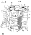
- Fig.2 shows a three-dimensional sectional view of a housing of a compressed air treatment plant with a mounted screen element.
- the illustrated housing 30 has, in particular, an air dryer cartridge connection 82 on the upper side of the housing 30.
- an insertion channel 26 extends from above into the housing 30, wherein the insertion channel 26 is freely accessible from above, as long as the air dryer cartridge 14, not shown, is not mounted on the housing 30.
- the sieve element 24 is shown, wherein of the sieve element 24 is substantially a passage surface 32, that is, the surface of the actual sieve or the sieve surface, visible.
- a mounting member 42 is further shown, which is designed as a bracket which is pressed during assembly of the air dryer cartridge on the housing 30 down into the insertion channel 26, whereby the screen element 24 in the position shown within the Insertion channel 26 can be clamped.
- the illustrated insertion channel 26 extends in the axial direction 28 in the housing 30, wherein the axial direction 28 coincides with a mounting direction of the air dryer cartridge, not shown.
- the axial direction 28 in which the insertion channel 26 extends in the housing 30 does not coincide with the mounting direction of the air dryer cartridge.
- an access opening be provided for the insertion channel 26, which is not covered with mounted air dryer cartridge of this, but has its own cover. In this way, an exchange of the screen element 24 can be made without having to dismantle the air dryer cartridge.
- the mounting element 42 is optional.
- the passage area 32 of the screen element 24 can extend up to the height of the air dryer cartridge connection 82, so that when the air dryer cartridge is mounted, the screen element 24 rests flush with the air dryer cartridge without the intermediary of a mounting element 42 and is fixed in the insertion channel 26 in this manner.
- the screen element 24 is fixedly coupled to the air dryer cartridge, not shown.
- the assembly process can be simplified, since during assembly of the air dryer cartridge automatically the screen element 24 is mounted.
- the coupling of the air dryer cartridge with the screen element 24 can be fixed, that is rigid, or flexible, that is movable, done.
- the mounting member 42 may be connected to a bottom plate, not shown, of the air dryer cartridge.
- the design of the coupling between the air dryer cartridge and the screen element is adapted to the possibility of connecting the air dryer cartridge to the housing 30.
- Figure 3 shows a further three-dimensional sectional view of a housing of a compressed air treatment plant with a mounted screen element.
- the arranged inside the housing 30 screen member 24 is seen only from the side, so that the Fig.2 already known passage surface 32 is substantially as a parallel to the axial direction 28 occidentalrekkende line emerges.
- the passage surface 32 divides the insertion channel 26 in the axial direction 28 in a downstream side 38 and an inflow side 40.
- unprocessed compressed air from a compressor port 84 which can be identified with the compressed air inlet 12 or connected thereto, in the housing 30th promoted there, rises there in the insertion channel 26 on the inflow side 40 along up to the air dryer cartridge port 82 and from there into the interior of the compressed air treatment plant 10.
- the flow direction is reversed and already processed compressed air
- the regeneration the air dryer cartridge flows from the air dryer cartridge port 82 on the upstream side 40 down through the insertion channel at the passage surface 32 along.
- the air can not reach the downstream side 38 without passing through the passage surface 32, since a cross-sectional area 34 of the insertion channel 26 is suitably partially blocked.
- This embodiment of the screening element 24 is in the FIGS. 4 and 5 even more clearly visible.
- the laden with oil and dirt particles and moisture regeneration air passes through the passage surface 32 on the downstream side 38, wherein the coarse dirt particles are retained at the passage surface 32.
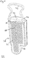
- FIG. 4 shows a three-dimensional view of a sieve element.
- the illustrated sieve element 24 comprises a frame 86, in which the passage surface 32 is arranged.
- the passage area 32 comprises a screen grid, wherein the openings within the grid have a diameter of between about 0.5 and 1.5 millimeters, preferably about 1.0 millimeters, and the intermediate grid bars have a width between about 0.5 millimeters and 0.9 Millimeters, preferably about 0.7 millimeters.
- Shown is the downstream side 38 of the screen element 24, on which a web 88 is arranged perpendicular to the passage surface 32 in the screen surface, which prevents a concern of the passage surface 32 against the wall of the insertion channel in the mounted state under varying pressure conditions.
- the web 88 further increases the stability of the passage surface 32 against bending during assembly.
- the cross-sectional area 34 of the insertion channel 26 can be seen, this being subdivided into a head surface 36 which, together with the passage surface 28, separates the downstream side 38 from the inflow side 40 in the insertion channel 26.
- the mounting member 42 in the form of a stirrup, which can be designed to be elastic and a Absetz phenomenon 44, which protects the inner wall of the insertion channel from dirt, visible.
- Figure 5 shows a further three-dimensional view of a sieve element.
- This in Figure 5 A large part of the inflow side 40 is covered by a molded part 90, which may rest in the mounted state on a wall of the insertion channel and on its the passage surface 32 side facing out of Figure 4 provides known settling surface 44.
- the molded part 90 thus forms a basket-like depression in which oil and dirt particles can collect.
- the lower edge of the frame 86 may be as in FIG Figure 5 be shown widened on the inflow side 40, so that 40 falling oil and dirt particles can accumulate on the frame 86 on the inflow side. This can be assisted by pulling an edge of the frame 86 up to form a pocket.
Landscapes
- Engineering & Computer Science (AREA)
- Mechanical Engineering (AREA)
- Transportation (AREA)
- Chemical & Material Sciences (AREA)
- Analytical Chemistry (AREA)
- Physics & Mathematics (AREA)
- Fluid Mechanics (AREA)
- General Engineering & Computer Science (AREA)
- Valves And Accessory Devices For Braking Systems (AREA)
- Cooling, Air Intake And Gas Exhaust, And Fuel Tank Arrangements In Propulsion Units (AREA)
- Compressor (AREA)
- Drying Of Gases (AREA)
Abstract
Description
- Die vorliegende Erfindung betrifft ein Siebelement zum Einschieben in einen Einschubkanal einer Entlüftungsleitung einer Druckluftaufbereitungsanlage für ein Fahrzeug gemäß Anspruch 1.
- Die vorliegende Erfindung betrifft weiterhin auch eine Druckluftaufbereitungsanlage für ein Fahrzeug, insbesondere für ein Nutzfahrzeug, mit einem Einschubkanal, der sich in einer axialen Richtung in einem Gehäuse der Druckluftaufbereitungsanlage erstreckt, wobei ein solches Siebelement in der axialen Richtung in den Einschubkanal eingeschoben ist, gemäß Anspruch 11.
- Druckluftaufbereitungsanlagen sind ein zentraler Bestandteil der Druckluftversorgungsanlagen von Fahrzeugen, insbesondere Nutzfahrzeugen, wie beispielsweise Lastkraftwagen und Schienenfahrzeuge. Derartige Fahrzeuge weisen Teilsysteme auf, welche mit Druckluft betrieben werden. Zu diesen Teilsystemen können beispielsweise die Bremsen des Fahrzeugs gehören. Die verdichtete Druckluft wird in der Regel mithilfe eines ölgeschmierten Kompressors erzeugt, der Umgebungsluft ansaugt und verdichtet. Ein Teil des zur Kompressorschmierung verwendeten Öls wird während des Kompressorbetriebs von der verdichteten Luft aufgenommen und gelangt über den Kompressorausgang in das nachgeordnete Leitungssystem. Um eine Kontaminierung des gesamten nachgeordneten Druckluftsystems mit schädlichen Öl- und Schmutzpartikeln und der in der Druckluft vorhandenen Luftfeuchtigkeit zu verhindern, ist üblicherweise eine Druckluftaufbereitungsanlage zwischen dem Kompressor und den einzelnen Druckluftverbrauchern angeordnet, die die vom Kompressor bereitgestellte Druckluft von Öl- und sonstigen Schmutzpartikeln reinigt und die in ihr enthaltene Feuchtigkeit zurückhält. Zu diesem Zweck kann eine Lufttrocknerpatrone vorgesehen sein, die sowohl Öl- und Schmutzpartikel zurückhält als auch mithilfe eines Trockenmittels der Druckluft Feuchtigkeit entzieht.
- Um die Lebensdauer dieser Lufttrocknerpatrone zu erhöhen und um den Energieverbrauch der Druckluftversorgungsanlage insgesamt zu reduzieren, ist es bekannt, bereits aufbereitete Druckluft in umgekehrter Strömungsrichtung durch die Lufttrocknerpatrone strömen zu lassen, um diese zu regenerieren. Die hierfür verwendete Regenerationsluft wird über eine Entlüftung aus dem System abgeführt, welche an die Druckluftförderleitung, das heißt die Verbindungsleitung zwischen dem Kompressor und der Luftfilterpatrone, abgeschlossen ist. Um einen dauerhaften Druckverlust über diese Entlüftung zu verhindern, wird eine Ventileinrichtung in Form eines Absperrventils vorgesehen, die den Druckluftpfad zur Entlüftung im Normalbetrieb verschließt. Aufgrund der Positionierung des Absperrventils "vor" der Lufttrocknerpatrone steht dieses Absperrventil ständig in Kontakt mit nicht aufbereiteter Druckluft, so dass erhöhte Anforderungen an das Absperrventil gestellt werden müssen, insbesondere hinsichtlich der Robustheit.
- Aufgrund von stetig steigenden Betriebsdrücken der verwendeten Druckluftanlagen mit höheren Temperaturen im Motorraum steigt gleichzeitig auch die Temperatur der komprimierten Luft in dem Kompressor am Ende eines Verdichtungstaktes an. Steigende Temperaturen der schmutzbehafteten verdichteten Luft verursachen jedoch verstärkt eine Verkohlung der aufgenommenen Ölund Schmutzpartikel, die sich im Inneren der Anlage niederschlagen und ansammeln können und nur schwer aus dem System entfernbar sind. Diese Verkohlungen stellen kleine Feststoffpartikel dar, die insbesondere bei einer Aggregation zu größeren Partikeln die Funktionsfähigkeit des Absperrventils beeinträchtigen können. Das kann zu einem Verklemmen oder zu einem nicht mehr vollständig schließenden Absperrventil führen.
- Der vorliegenden Erfindung liegt daher die Aufgabe zugrunde, eine Druckluftaufbereitungsanlage und insbesondere deren Ablassventil vor derartigen Verkohlungen und Verschmutzungen zu schützen.
- Diese Aufgabe wird mit den Merkmalen der unabhängigen Ansprüche gelöst.
- Die Erfindung stellt ein Siebelement zum Einschieben in einen Einschubkanal einer Entlüftungsleitung einer Druckluftaufbe-reitungsanlage für ein Fahrzeug, insbesondere für ein Nutzfahrzeug zur Verfügung, welches wenigstens Folgendes beinhaltet: Einen Rahmen, eine in dem Rahmen angeordnete Durchtrittsfläche umfassend ein Siebgitter, wobei Öffnungen innerhalb des Siebgitters einen Durchmesser zwischen 0,5 mm und 1,5 mm aufweisen.
- Mit einem solchen Siebelement ist eine zuverlässiges Zurückhalten von schädlichen Partikeln und Verschmutzungen möglich, wie sie in Ihrer Größe gerade in Druckluftaufbereitungsanlagen kursieren. Insbesondere können bei einer geeigneten Positionierung des Siebelements in der Druckluftaufbereitungsanlage Teile der Druckluftaufbereitungsanlage vor Verschmutzung oder Beschädigung geschützt werden.
- Vorteilhafte Ausführungsformen der Erfindung sind in den abhängigen Ansprüchen angegeben.
- Bevorzugt weisen zwischen den Öffnungen des Siebgitters liegende Gitterstege eine Breite zwischen 0,5 mm und 0,9 mm auf. Diese Maßnahme trägt ebenfalls zu einem zuverlässigen Zurückhalten von schädlichen Partikeln und Verschmutzungen bei.
- Gemäß einer Weiterbildung umfasst das Siebelement eine Kopffläche, die zusammen mit der Durchtrittsfläche eine Abströmseite des Siebelements von einer Anströmseite des Siebelements trennt. Es ist allerdings auch denkbar, dass die Kopffläche ebenfalls als eine weitere Durchtrittsfläche wirkt, um die insgesamt vorhandene Durchtrittsfläche weiter zu vergrößern.
- Bevorzugt kann auf der Abströmseite des Siebelements ein Steg senkrecht zur Durchtrittsfläche angeordnet sein. Der Steg verhindert ein Anliegen der Durchtrittsfläche an die Wandung des Einschubkanals im montierten Zustand bei wechselnden Druckverhältnissen. Der Steg erhöht weiterhin die Stabilität der Durchtrittsfläche gegenüber Verbiegen bei der Montage.
- Besonders bevorzugt kann auch ein Teil der Anströmseite des Siebelements durch ein Formteil verdeckt sein, welches auf seiner der Durchtrittsfläche zugewandten Seite eine Absetzfläche aufweist, wobei eine korbartige Vertiefung zum Sammeln von Öl- und Schmutzpartikeln ausgebildet wird. Vorteilhafterweise kann daher vorgesehen sein, dass das Siebelement eine Absetzfläche umfasst. Die Absetzfläche, die beispielsweise bei montiertem Siebelement in dem Einschubkanal zumindest teilweise an der Wand des Einschubkanals anliegt, schützt ebenfalls beispielsweise ein Absperrventil der Druckluftaufbereitungsanlage vor schädlichen Verkohlungen. Bei einer Demontage wird die Absetzfläche mitgetauscht, so dass das neue Siebelement in einen von Verkohlungen im Wesentlichen freien Einschubkanal eingeschoben oder eingeschraubt wird. Es wird daher vermieden, bei der Montage eines neuen Siebelementes Verkohlungen hinter das neue Siebelement zu verschieben.
- Gemäß einer weiterhin zu bevorzugenden Maßnahme kann ein in Einbaulage des Siebelements in dem Einschubkanal unterer Rand des Rahmens auf der Anströmseite verbreitert sein. Dabei ist insbesondere eine Kante des Rahmens nach oben gezogen, um eine Tasche auszubilden.
- Besonders bevorzugt umfasst das Siebelement ein Montageelement in Form eines Haltebügels, welcher in einem in den Einschubkanal eingeschobenen Zustand des Siebelements aus dem Einschubkanal herausragt. Insbesondere kann der Bügel elastisch ausgebildet sein. Das Montageelement ist daher bevorzugt als einfacher Haltebügel ausgeführt, welcher über das Gehäuse hinausragen kann. Auf diese Weise ist ein besonders einfacher Zugriff auf das Siebelement möglich, da durch das Greifen des Halteelementes das Siebelement in einfacher Weise aus dem Einschubkanal herausgezogen beziehungsweise herausgeschraubt werden kann. Das Halteelement kann flexibel ausgebildet sein, um ein Verschließen des Einschubkanals beziehungsweise des Gehäuses zu ermöglichen, falls das Montageelement über das Gehäuse hinausragt.
- Gemäß einer Weiterbildung kann das Siebelement mit einer Lufttrocknerpatrone der Druckluftaufbereitungsanlage starr oder flexibel gekoppelt sein. Durch das Koppeln, das heißt das Verbinden von Lufttrocknerpatrone und Siebelement kann insbesondere die Montage des Siebelementes erleichtert werden, da das Siebelement dann gemeinsam mit der Lufttrocknerpatrone montierbar ist, ohne dass weitere zusätzliche Montageschritte notwendig wären. Darüber hinaus kann eine gleichmäßige Wartung der Druckluftaufbereitungsanlage gewährleistet werden, da der Tausch der Lufttrocknerpatrone zwangsläufig gleichzeitig mit dem Tausch des Siebelementes erfolgt.
- Das Siebelement selbst kann zudem die Montage der Lufttrocknerpatrone vereinfachen, beispielsweise durch Verwendung des Siebelements als Führungszapfen, der das Zusammenführen von Lufttrocknerpatrone und Gehäuse erleichtert. Darüber hinaus kann über die Form des Siebelementes zugleich sichergestellt werden, dass nur geeignete Lufttrocknerpatronen auf dem Gehäuse der Luftaufbereitungsanlage montierbar sind.
- Die Erfindung stellt auch eine Druckluftaufbereitungsanlage für ein Fahrzeug, insbesondere für ein Nutzfahrzeug zur Verfügung, mit einem Einschubkanal, der sich in einer axialen Richtung in einem Gehäuse der Druckluftaufbereitungsanlage erstreckt, wobei ein Siebelement nach wenigstens einem der vorhergehenden Ansprüche in der axialen Richtung in den Einschubkanal eingeschoben ist.
- Gemäß einer Weiterbildung kann die Druckluftaufbereitungsanlage Folgendes umfassen: Einen Drucklufteingang, eine Lufttrocknerpatrone, die über eine Druckluftförderleitung mit dem Drucklufteingang gekoppelt ist, und ein Ablassventil, das in einer an einem Verzweigungspunkt von einer Druckluftförderleitung abzweigenden Entlüftungsleitung ange- ordnet ist, wobei ein oben beschriebenes Siebelement zwischen dem Verzweigungspunkt und dem Ablassventil in der Entlüftungsleitung angeordnet ist, welche zumindest teilweise als der Einschubkanal ausgeführt ist.
- Nützlicherweise ist daher vorgesehen, dass die Entlüftungsleitung zumindest teilweise als ein Einschubkanal ausgeführt ist, der sich in einer axialen Richtung in einem Gehäuse der Druckluftaufbereitungsanlage erstreckt, wobei ein oben beschriebenes Siebelement in der axialen Richtung in den Einschubkanal einschiebbar oder eingeschoben ist. Die Einschiebbarkeit des Siebelementes erlaubt eine leichte Zugänglichkeit des Siebelementes, die eine Voraussetzung für eine einfache Montage und Demontage darstellt. Unter einschiebbar kann dabei sowohl eine einfache geradlinige Bewegung, das heißt ein Einschieben, in der axialen Richtung als auch eine Schraubbewegung um die axiale Richtung verstanden werden. Die axiale Richtung kann vorzugsweise parallel zu einer Montagerichtung der Lufttrocknerpatrone liegen, prinzipiell ist jedoch auch jede andere Orientierung der axialen Richtung relativ zu der Montagerichtung denkbar. Der Einschubkanal ist dabei von der Gehäuseaußenseite zugänglich, um einen Montagezugriff zu gewährleisten.
- Die Durchtrittsfläche unterteilt beispielsweise den Einschubkanal in der axialen Richtung in eine Abströmseite und eine Anströmseite. Im Betrieb wird nicht aufbereitete Druckluft von einem Kompressoranschluss, der mit dem Drucklufteingang identifiziert werden kann oder mit diesem verbunden ist, in das Gehäuse gefördert, steigt dort in dem Einschubkanal an der Anströmseite entlang nach oben zu einem Lufttrocknerpatronenanschluss und gelangt von dort weiter in das Innere der Druckluftaufbereitungsanlage. Während eines Regenerationsbetriebs wird die Strömungsrichtung umgekehrt und bereits aufbereitete Druckluft, die zur Regeneration der Lufttrocknerpatrone verwendet wurde, strömt von dem Lufttrocknerpatronenanschluss auf der Anströmseite nach unten durch den Einschubkanal an der Durchtrittsfläche entlang. Die Luft kann nicht auf die Abströmseite gelangen, ohne durch die Durchtrittsfläche hindurchzutreten, da eine Querschnittsfläche des Einschubkanals in geeigneter Weise teilweise blockiert ist. Die mit Öl- und Schmutzpartikeln und Feuchtigkeit beladene Regenerationsluft tritt durch die Durchtrittsfläche auf die Abströmseite über, wobei die groben Schmutzpartikel an der Durchtrittsfläche zurückgehalten werden.
- Das Siebelement umfasst, wie oben beschrieben einen Rahmen, in dem die Durchtrittsfläche angeordnet ist. Die Durchtrittsfläche umfasst ein Siebgitter, wobei die Öffnungen innerhalb des Gitters einen Durchmesser zwischen etwa 0,5 und 1,5 Millimeter, vorzugsweise etwa 1,0 Millimeter aufweisen und die dazwischen liegenden Gitterstege eine Breite zwischen etwa 0,5 Millimeter und 0,9 Millimeter, vorzugsweise etwa 0,7 Millimeter aufweisen. Auf der Abströmseite des Siebelementes ist beispielsweise ein Steg senkrecht zu der Durchtrittsfläche in der Siebfläche angeordnet, der ein Anliegen der Durchtrittsfläche an die Wandung des Einschubkanals im montierten Zustand bei wechselnden Druckverhältnissen verhindert. Der Steg erhöht weiterhin die Stabilität der Durchtrittsfläche gegenüber Verbiegen bei der Montage. Im oberen Bereich des Siebelementes unterteilt bevorzugt eine Kopffläche gemeinsam mit der Durchtrittsfläche die Abströmseite von der Anströmseite im Einschubkanal. Das Montageelement kann in Form eines Bügels ausgeführt werden, der elastisch ausführt sein kann, Weiterhin kann das Siebelement eine Absetzfläche aufweisen, die die Innenwand des Einschubkanals vor Verschmutzungen schützt.
- Ein großer Teil der Anströmseite des Siebelements ist beispielsweise durch ein Formteil verdeckt, welches im montierten Zustand an einer Wandung des Einschubkanals anliegen kann und auf seiner der Durchtrittsfläche zugewandten Seite die Absetzfläche bereitstellt. Das Formteil bildet somit bevorzugt eine korbartige Vertiefung aus, in der sich Öl- und Schmutzpartikel sammeln können. Der untere Rand des Rahmens kann auf der Anströmseite verbreitert sein, so dass sich an der Anströmseite herunterfallende Öl- und Schmutzpartikel auf dem Rahmen ansammeln können. Dies kann dadurch unterstützt werden, dass eine Kante des Rahmens nach oben gezogen wird, um eine Tasche auszubilden.
- Die Erfindung sieht insbesondere vor, dass ein oben beschriebenes Siebelement zumindest teilweise zwischen dem Verzweigungspunkt und dem Ablassventil in der Entlüftungsleitung angeordnet ist. Durch das Vorsehen des Siebelementes werden die unerwünschten großen Feststoffpartikel, die die Funktionsfähigkeit des Ablassventils stören könnten, zurückgehalten, während kleinere Feststoffpartikel, die für das Ablaufventil unkritisch sind, ungehindert durch das Ablassventil hindurchtreten können. Die Formulierung "zumindest teilweise zwischen dem Verzweigungspunkt und dem Ablassventil in der Entlüftungsleitung angeordnet" ist so zu verstehen, dass ein Teil oder das gesamte Siebelement in der Entlüftungsleitung in Strömungsrichtung vor dem Ablassventil positioniert ist. Es ist dabei denkbar, dass ein Teil des Siebelementes in die Druckluftförderleitung zwischen dem Kompressor und der Lufttrocknerpatrone hineinragt und dabei eventuell den Verzweigungspunkt bildet oder über diesen sogar hinausragt. Das muss allerdings nicht der Fall sein. Dann kann das Siebelement vollständig zwischen dem Verzweigungspunkt und dem Ablassventil liegen.
- Vorteilhafterweise kann vorgesehen sein, dass eine Durchtrittsfläche des Siebelements senkrecht zu einer Querschnittsfläche des Einschubkanals liegt. Die Querschnittsfläche bezeichnet in üblicher Weise die Fläche in der Ebene senkrecht zu der axialen Erstreckungsrichtung des Einschubkanals. Die Durchtrittsfläche bezeichnet die aktive Siebfläche, durch die die zu siebende Luft während des Siebens strömt. Durch die besondere Orientierung der Durchtrittsfläche kann die Fläche des Siebes, die aktiv während des Siebens wirkt, im Verhältnis zu der Querschnittsflä- che des Einschubkanals vergrößert werden, so dass der Staudruck des Siebele- mentes durch Beladung des Siebelementes mit ausgesiebten Partikeln reduziert wird. Je nach Bedarf kann auch eine andere Orientierung der Durchtrittsfläche relativ zu der Querschnittsfläche gewählt werden, beispielsweise um Staudrücke innerhalb des Systems zu reduzieren oder um das Ablagern der ausgesiebten Partikel zu beeinflussen.
- Vorteilhafterweise kann auch vorgesehen sein, dass die Lufttrocknerpatrone das Siebelement in dem Einschubkanal fixiert. Auf diese Weise kann die korrekte Positionierung des Siebelementes in dem Einschubkanal dauerhaft gewährleistet werden, insbesondere auch während des Betriebs der Druckluftaufbereitungsanlage der üblicherweise fahrbedingt mit mehr oder weniger starken Vibrationen einher- geht, die ansonsten ein Verrutschen des Siebelementes verursachen könnten. Die Fixierung kann dabei in der Ausübung einer Haltekraft auf das Siebelement bestehen, beispielsweise durch ein bündiges Abschließen der montierten Lufttrockner- patrone mit dem Siebelement, oder über ein elastisches Element erfolgen, beispielsweise das Montageelement, welches bei montierter Lufttrocknerpatrone das Siebelement in seiner Montageposition verspannen kann, wenn die Lufttrockner- patrone das Montageelement in den Einschubkanal drückt.
- Die Erfindung wird nun mit Bezug auf die begleitenden Zeichnungen anhand bevorzugter Ausführungsformen beispielhaft erläutert.
- Es zeigen:
-
Fig.1 einen Ausschnitt aus einer schematisch dargestellten Druckluftaufbereitungsanlage; -
Fig.2 ein dreidimensionales Schnittbild eines Gehäuses einer Druckluftaufbereitungsanlage mit einem montierten Siebelement; -
Fig.3 ein weiteres dreidimensionales Schnittbild eines Gehäuses einer Druckluftaufbereitungsanlage mit einem montierten Siebelement; -
Fig.4 eine dreidimensionale Ansicht eines Siebelementes; und -
Fig.5 eine weitere dreidimensionale Ansicht eines Siebelementes. - In der folgenden Beschreibung von Ausführungsbeispielen bezeichnen gleiche Bezugszeichen gleiche oder gleichartige Teile.
-
Fig.1 zeigt einen Ausschnitt einer schematisch dargestellten Druckluftaufbereitungsanlage. Die nur teilweise dargestellte Druckluftaufbereitungsanlage 10 weist einen Drucklufteingang 12 auf, an dem üblicherweise ein Kompressor angeschlossen ist. Darüber hinaus umfasst die Druckluftaufbereitungsanlage 10 einen Fremd- befüllungsanschluss 76 über den ebenfalls Druckluft aus einer externen Druckluft- quelle der Druckluftaufbereitungsanlage 10 zugeführt werden kann, beispielsweise zu Servicezwecken in einer Werkstatt. Weiterhin ist ein Datenbusanschluss 78 vorgesehen, über den die Druckluftaufbereitungsanlage 10 mit anderen Teilsystemen des Nutzfahrzeugs, beispielsweise einer Motorsteuerung, kommunizieren kann. Die Druckluftaufbereitungsanlage 10 umfasst eine Druckluftförderleitung 16, die den Drucklufteingang 12 mit einer Lufttrocknerpatrone 14 verbindet. Die Lufttrocknerpatrone 14 reinigt die geförderte Druckluft von Öl- und Schmutzpartikeln und entzieht ihr Feuchtigkeit. Zu diesem Zweck umfasst die Lufttrocknerpatrone 14 üblicherweise Koaleszenzfilter oder sonstige Filtereinrichtungen zum Entfernen der Öl- und Schmutzpartikel und ein hygroskopisches Trockenmittel. Die aufbereitete Druckluft wird stromabwärts der Lufttrocknerpatrone 14 über ein Rückschlagventil 46 weitergeleitet. Angedeutet ist ein Mehrkreisschutzventilanschluss 70, wobei das nicht mehr dargestellte Mehrkreisschutzventil eine von der Druckluftaufbereitungsanlage 10 getrennte oder eine in die Druckluftaufbereitungsanlage 10 integrierte Komponente sein kann. Wenn die Kapazität des Trockenmittels der Lufttrocknerpatrone 14 erschöpft ist, kann aufbereitete Druckluft unter Umgehung des Rück- schlagventils 46 über eine Regenerationsleitung 58, ein weiteres Rückschlagventil 48 und eine Drossel 50 die Lufttrocknerpatrone 14 unter Umkehrung der Strömungsrichtung regenerieren. Dabei werden in der Lufttrocknerpatrone 14 gesammelte Öl- und Schmutzpartikel sowie in dem Trockenmittel gespeicherte Feuchtig- keit aus der Lufttrocknerpatrone 14 ausgespült. Die Regenerationsluft strömt weiter rückwärts durch die Druckluftförderleitung 16 bis zu einem Verzweigungspunkt 20 und von dort über eine Entlüftungsleitung 22 zu einer Entlüftung 80. In der Entlüftungsleitung 22 ist ein Ablassventil 18 angeordnet, das beispielsweise als 2/2-Wegeventil ausgeführt sein kann. Zwischen dem Verzweigungspunkt 20 und dem Ablassventil 18 ist weiterhin ein Siebelement 24 angeordnet, das grobe Schmutz- partikel zurückhält. Der Regenerationszyklus kann über ein Regenerationsmagnetventil 56, das in der Regenerationsleitung 58 angeordnet ist und beispielsweise als 3/2-Wegeventil ausgeführt sein kann, gesteuert werden. Über eine Steuerleitung 52, die von der Regenerationsleitung 58 an einem Abzweigpunkt 54 entspringt, kann eine Schließfeder 92 des Absperrventils 18 vorgespannt werden, um den pneumatischen Öffnungsdruck des Absperrventils 18 anzupassen, beispielsweise zwischen einem Öffnungsdruck von etwa 9,5 bis 10 bar, wenn die Steuerleitung 52 drucklos ist, und einem Öffnungsdruck von etwa 16 bis 17 bar, wenn die Steuerleitung 52 mit Druck beaufschlagt ist. Das Absperrventil 18 kann über eine weitere Steuerleitung 60 in der ein beispielsweise als 3/2-Wegeventil ausgeführtes Magnetventil 62 angeordnet ist, pneumatisch angesteuert werden. Um die Regenerationsluft über die Entlüftung 80 abzulassen, können sowohl das Regenerationsmagnetventil 56 als auch das Magnetventil 62 gleichzeitig angesteuert werden, so dass die Regenerationsluft über das Siebelement 24 und das Absperrventil 18 zu der Entlüftung 80 gelangt, um dort aus dem System auszutreten. Die weitere Steuerleitung 60 kann einen weiteren Abzweigpunkt 94 aufweisen, über den eine weitere Ventileinrichtung 74 angesteuert sein kann, welche wiederum einen nicht dargestellten Kompressor, der die Druckluft an dem Drucklufteingang 12 bereitstellt, in einen energiesparenden Betriebszustand versetzen kann. Die Ventileinrichtung 74 kann insbesondere eine besonders schnelle Entlüftung der weiteren Steuerleitung 60 ermöglichen, um den Betriebszustand des Kompressors schneller zu ändern. In einem solchen energiesparenden Zustand ist gleichzeitig das Absperrventil 18 angesteuert, so dass eine üblicherweise reduzierte Druckluftfördermenge des Kompressors direkt von dem Drucklufteingang über das Siebelement 24 und das Absperrventil 18 durch die Entlüftung 80 aus dem System austritt. Eine reduzierte Druckluftfördermenge kann beispielsweise etwa 20 Prozent des normalerweise geförderten Druckluftvolumens betragen. Die Entlüftung 80 kann, wie inFig.1 angedeutet, mit weiteren nicht dargestellten Komponenten der Druckluftaufbereitungsanlage 10 über eine weitere Entlüftungsleitung 72 gekoppelt sein. Diese Komponenten können ebenfalls die Entlüftung 80 zum Ausstoß von Druckluft aus dem System nutzen. Weiterhin kön- nen die an dem Regenerationsmagnetventil 56 und dem Magnetventil 62 angedeu- teten Entlüftungen auch mit der Entlüftung 80 gekoppelt sein, wobei auf die explizite Darstellung entsprechender Verbindungsleitungen zur besseren Übersicht verzichtet wurde. Die Druckluftaufbereitungsanlage 10 umfasst ein Steuergerät 64, welches das Regenerationsmagnetventil 56 und das Magnetventil 62 ansteuern kann und über den Datenbusanschluss 78 mit weiteren Teilsystemen des Nutzfahrzeugs gekoppelt sein kann. Angedeutet sind weiterhin eine Heizung 68 und ein Drucksensor 66, die von dem Steuergerät 64 gesteuert wird, beziehungsweise über die das Steuergerät 64 Informationen über die in der Druckluftaufbereitungsanlage 10 herrschenden Druckniveaus erhält. Die Heizung 68 kann insbesondere zur Vermei- dung des Zufrierens von Druckleitungen genutzt werden. Der Drucksensor 66 ist nur exemplarisch für eine ganze Anzahl von Drucksensoren zu verstehen, die den Druck in der Druckluftaufbereitungsanlage 10 an den verschiedensten Stellen messen können. Insbesondere können vor und hinter dem Siebelement 24 in der Entlüftungsleitung 22 Drucksensoren angeordnet sein, um einen an dem Siebelement 24 abfallenden Staudruck zu bestimmen, wenn das Ablassventil 18 geöffnet ist. Auf diese Weise kann eine Verstopfung des Siebelementes 24 erkannt werden, die das Entweichen der Druckluft während eines Regenerationszyklus behindern würde, wobei diese Verstopfung ein Wechselkriterium darstellen kann. Das Ablassventil 18 dient weiterhin als Sicherheitsventil, um einen gefährlichen Druckanstieg in der Druckluftaufbereitungsanlage 10 zu verhindern. Zu diesem Zweck ist eine Steuerleitung 96 vorgesehen, über die das Ablassventil bei Überschreiten eines einstellbaren Sicherheitsdrucks geöffnet wird. -
Fig.2 zeigt ein dreidimensionales Schnittbild eines Gehäuses einer Druckluftaufbereitungsanlage mit einem montierten Siebelement. Das dargestellte Gehäuse 30 weist insbesondere einen Lufttrocknerpatronenanschluss 82 auf der Oberseite des Gehäuses 30 auf. In einer axialen Richtung 28 reicht ein Einschubkanal 26 von oben in das Gehäuse 30 hinein, wobei der Einschubkanal 26 von oben frei zugänglich ist, solange die nicht dargestellte Lufttrocknerpatrone 14 nicht an dem Gehäuse 30 montiert ist. In dem Einschubkanal 26 ist das Siebelement 24 dargestellt, wobei von dem Siebelement 24 im Wesentlichen eine Durchtrittsfläche 32, das heißt die Fläche des eigentlichen Siebs beziehungsweise die Siebfläche, sichtbar ist. Nach oben aus dem Einschubkanal 26 ragend ist weiterhin ein Montageelement 42 dargestellt, das als ein Bügel ausgeführt ist, welcher bei der Montage der Lufttrocknerpatrone an dem Gehäuse 30 nach unten in den Einschubkanal 26 gedrückt wird, wodurch das Siebelement 24 in der dargestellten Position innerhalb des Einschubkanals 26 verspannt werden kann. Der dargestellte Einschubkanal 26 erstreckt sich in der axialen Richtung 28 in dem Gehäuse 30, wobei die axiale Richtung 28 mit einer Montagerichtung der nicht dargestellten Lufttrocknerpatrone zusammenfällt. - Es ist jedoch auch denkbar, dass die axiale Richtung 28 in der sich der Einschubkanal 26 in dem Gehäuse 30 erstreckt nicht mit der Montagerichtung der Lufttrocknerpatrone zusammenfällt. Insbesondere kann eine Zugangsöffnung für den Einschubkanal 26 vorgesehen sein, die bei montierter Lufttrocknerpatrone nicht von dieser abgedeckt wird, sondern über eine eigene Abdeckung verfügt. Auf diese Weise kann ein Austausch des Siebelementes 24 vorgenommen werden, ohne die Lufttrocknerpatrone demontieren zu müssen. Das Montageelement 42 ist optional.
- Beispielsweise kann auch die Durchtrittsfläche 32 des Siebelementes 24 bis auf die Höhe des Lufttrocknerpatronenanschlusses 82 hinaufreichen, so dass bei montierter Lufttrocknerpatrone das Siebelement 24 bündig, ohne Vermittlung eines Montageelementes 42 an der Lufttrocknerpatrone ansteht und auf diese Weise in dem Einschubkanal 26 fixiert ist.
- Es ist weiterhin denkbar, dass das Siebelement 24 fest mit der nicht dargestellten Lufttrocknerpatrone gekoppelt ist. Auf diese Weise kann insbesondere der Montagevorgang vereinfacht werden, da bei einer Montage der Lufttrocknerpatrone automatisch das Siebelement 24 montiert wird. Die Kopplung der Lufttrocknerpatrone mit dem Siebelement 24 kann dabei fest, das heißt starr, oder flexibel, das heißt beweglich, erfolgen. Beispielsweise kann das Montageelement 42 mit einer nicht dargestellten Bodenplatte der Lufttrocknerpatrone verbunden sein. Die Ausführung der Kopplung zwischen der Lufttrocknerpatrone und dem Siebelement ist an die Anschlussmöglichkeit der Lufttrocknerpatrone an das Gehäuse 30 anzupassen.
- Verfügt der Lufttrocknerpatronenanschluss über eine Bajonettkopplung, das heißt, dass die Lufttrocknerpatrone ohne Drehbewegung auf das Gehäuse 30 aufgesetzt und verriegelt werden kann, so ist eine starre Kopplung zwischen dem Siebelement 24 und der Lufttrocknerpatrone besonders leicht möglich, wobei im Falle einer starren Kopplung das Siebelement 24 beispielsweise als eine Verdrehsicherung gegenüber dem Gehäuse bei der Montage der Lufttrocknerpatrone genutzt werden kann.
-
Fig.3 zeigt ein weiteres dreidimensionales Schnittbild eines Gehäuses einer Druckluftaufbereitungsanlage mit einem montierten Siebelement. Das im Inneren des Gehäuses 30 angeordnete Siebelement 24 ist lediglich von der Seite zu sehen, so dass sich die ausFig.2 bereits bekannte Durchtrittsfläche 32 sich im Wesentlichen als eine parallel zu der axialen Richtung 28 erstrekkende Linie abzeichnet. Die Durchtrittsfläche 32 unterteilt den Einschubkanal 26 in der axialen Richtung 28 in eine Abströmseite 38 und eine Anströmseite 40. Im Betrieb wird nicht aufbereitete Druckluft von einem Kompressoranschluss 84, der mit dem Drucklufteingang 12 identifiziert werden kann oder mit diesem verbunden ist, in das Gehäuse 30 geför- dert, steigt dort in dem Einschubkanal 26 an der Anströmseite 40 entlang nach oben zu dem Lufttrocknerpatronenanschluss 82 und gelangt von dort weiter in das Innere der Druckluftaufbereitungsanlage 10. Während eines Regenerationsbetriebs wird die Strömungsrichtung umgekehrt und bereits aufbereitete Druckluft, die zur Rege- neration der nicht dargestellten Lufttrocknerpatrone verwendet wurde, strömt von dem Lufttrocknerpatronenanschluss 82 auf der Anströmseite 40 nach unten durch den Einschubkanal an der Durchtrittsfläche 32 entlang. Die Luft kann nicht auf die Abströmseite 38 gelangen, ohne durch die Durchtrittsfläche 32 hindurchzutreten, da eine Querschnittsfläche 34 des Einschubkanals 26 in geeigneter Weise teilweise blockiert ist. Diese Ausgestaltung des Siebelementes 24 wird in denFiguren 4 und5 noch genauer ersichtlich. Die mit Öl- und Schmutzpartikeln und Feuchtigkeit beladene Regenerationsluft tritt durch die Durchtrittsfläche 32 auf die Abströmseite 38 über, wobei die groben Schmutzpartikel an der Durchtrittsfläche 32 zurückgehalten werden. -
Fig.4 zeigt eine dreidimensionale Ansicht eines Siebelementes. Das dargestellte Siebelement 24 umfasst einen Rahmen 86, in dem die Durchtrittsfläche 32 angeordnet ist. Die Durchtrittsfläche 32 umfasst ein Siebgitter, wobei die Öffnungen innerhalb des Gitters einen Durchmesser zwischen etwa 0,5 und 1,5 Millimeter, vorzugsweise etwa 1,0 Millimeter aufweisen und die dazwischen liegenden Gitterstege eine Breite zwischen etwa 0,5 Millimeter und 0,9 Millimeter, vorzugsweise etwa 0,7 Millimeter aufweisen. Dargestellt ist die Abströmseite 38 des Siebelementes 24, auf der ein Steg 88 senkrecht zu der Durchtrittsfläche 32 in der Siebfläche angeordnet ist, der ein Anliegen der Durchtrittsfläche 32 an die Wandung des Einschubkanals im montierten Zustand bei wechselnden Druckverhältnissen verhindert. Der Steg 88 erhöht weiterhin die Stabilität der Durchtrittsfläche 32 gegenüber Verbiegen bei der Montage. Im oberen Bereich des Siebelementes 24 ist die Querschnittsfläche 34 des Einschubkanals 26 erkennbar, wobei diese unterteilt ist in eine Kopffläche 36, die gemeinsam mit der Durchtrittsfläche 28 die Abströmseite 38 von der Anströmseite 40 im Einschubkanal 26 trennt. Weiterhin sind das Montageelement 42 in Form eines Bügels, der elastisch ausführt sein kann und eine Absetzfläche 44, die die Innenwand des Einschubkanals vor Verschmutzungen schützt, sichtbar. -
Fig.5 zeigt eine weitere dreidimensionale Ansicht eines Siebelementes. Das inFig.5 dargestellte Siebelement 24 zeigt die Anströmseite 40 des Siebelementes 24. Ein großer Teil der Anströmseite 40 ist durch ein Formteil 90 verdeckt, welches im montierten Zustand an einer Wandung des Einschubkanals anliegen kann und auf seiner der Durchtrittsfläche 32 zugewandten Seite die ausFig.4 bekannte Absetzfläche 44 bereitstellt. Das Formteil 90 bildet somit eine korbartige Vertiefung aus, in der sich Öl- und Schmutzpartikel sammeln können. Der untere Rand des Rahmens 86 kann wie inFig.5 dargestellt auf der Anströmseite 40 verbreitert sein, so dass sich an der Anströmseite 40 herunterfallende Öl- und Schmutzpartikel auf dem Rahmen 86 ansammeln können. Dies kann dadurch unterstützt werden, dass eine Kante des Rahmens 86 nach oben gezogen wird, um eine Tasche auszubilden. - Die in der vorstehenden Beschreibung, in den Zeichnungen sowie in den Ansprüchen offenbarten Merkmale der Erfindung können sowohl einzeln als auch in beliebiger Kombination für die Verwirklichung der Erfindung wesentlich sein.
-
- 10
- Druckluftaufbereitungsanlagege
- 12
- Drucklufteingang
- 14
- Lufttrocknerpatrone
- 16
- Druckluftförderleitung
- 18
- Ablassventil
- 20
- Verzweigungspunkt
- 22
- Entlüftungsleitung
- 24
- Siebelement
- 26
- Einschubkanal
- 28
- axiale Richtung
- 30
- Gehäuse
- 32
- Durchtrittsfläche
- 34
- Querschnittsfläche
- 36
- Kopffläche
- 38
- Abströmseite
- 40
- Anströmseite
- 42
- Montageelement
- 44
- Absetzfläche
- 46
- Rückschlagventil
- 48
- weiteres Rückschlagventil
- 50
- Drossel
- 52
- Steuerleitung
- 54
- Abzweigpunkt
- 56
- Regenerationsmagnetventil
- 58
- Regenerationsleitung
- 60
- weitere Steuerleitung
- 62
- Magnetventil
- 64
- Steuergerät
- 66
- Drucksensor
- 68
- Heizung
- 70
- Mehrkreisschutzventilanschluss
- 72
- weitere Entlüftungsleitung
- 74
- Ventileinrichtung
- 76
- Fremdbefüllungsanschluss
- 78
- Datenbusanschluss
- 80
- Entlüftung
- 82
- Lufttrocknerpatronenanschluss
- 84
- Kompressoranschluss
- 86
- Rahmen
- 88
- Steg
- 90
- Formteil
- 92
- Schließfeder
- 94
- weiterer Abzweigpunkt
- 96
- Steuerleitung
Claims (12)
- Siebelement (24) zum Einschieben in einen Einschubkanal (26) einer Entlüftungsleitung (22) einer Druckluftaufbereitungsanlage (10) für ein Fahrzeug, insbesondere für ein Nutzfahrzeug, welches wenigstens Folgendes beinhaltet:a) Einen Rahmen (86),b) eine in dem Rahmen (86) angeordnete Durchtrittsfläche (32) umfassend ein Siebgitter, wobeic) Öffnungen innerhalb des Siebgitters einen Durchmesser zwischen 0,5 mm und 1,5 mm aufweisen.
- Siebelement (24) nach Anspruch 1, dadurch gekennzeichnet, dass zwischen den Öffnungen des Siebgitters liegende Gitterstege eine Breite zwischen 0,5 mm und 0,9 mm aufweisen.
- Siebelement (24) nach einem der vorhergehenden Ansprüche, dadurch gekennzeichnet, dass das Siebelement (24) eine Kopffläche (36) umfasst, die zusammen mit der Durchtrittsfläche (32) eine Abströmseite (38) des Siebelements (24) von einer Anströmseite (40) des Siebelements (24) trennt.
- Siebelement (24) nach Anspruch 3, dadurch gekennzeichnet, dass auf der Abströmseite (38) des Siebelements (24) ein Steg (88) senkrecht zur Durchtrittsfläche (32) angeordnet ist.
- Siebelement (24) nach Anspruch 3 oder 4, dadurch gekennzeichnet, dass ein Teil der Anströmseite (40) des Siebelements (24) durch ein Formteil (90) verdeckt ist, welches auf seiner der Durchtrittsfläche (32) zugewandten Seite eine Absetzfläche (44) aufweist, wobei eine korbartige Vertiefung zum Sammeln von Öl- und Schmutzpartikeln ausgebildet wird.
- Siebelement (24) nach einem der Ansprüche 2 bis 5, dadurch gekennzeichnet, dass ein in Einbaulage des Siebelements (24) in dem Einschubkanal (26) unterer Rand des Rahmens (86) auf der Anströmseite (40) verbreitert ist.
- Siebelement (24) nach Anspruch 6, dadurch gekennzeichnet, das eine Kante des Rahmens (86) nach oben gezogen ist, um eine Tasche auszubilden.
- Siebelement (24) nach einem der vorhergehenden Ansprüche, dadurch gekennzeichnet, dass es ein Montageelement (42) in Form eines Haltebügels umfasst, welcher in einem in den Einschubkanal (26) eingeschobenen Zustand des Siebelements (24) aus dem Einschubkanal (26) herausragt.
- Siebelement (24) nach Anspruch 8, dadurch gekennzeichnet, dass der Bügel elastisch ausgebildet ist.
- Siebelement (24) nach einem der vorhergehenden Ansprüche, dadurch gekennzeichnet, dass es mit einer Lufttrocknerpatrone (14) der Druckluftaufbereitungsanlage (10) starr oder flexibel gekoppelt ist.
- Druckluftaufbereitungsanlage (10) für ein Fahrzeug, insbesondere für einNutzfahrzeug, mit einem Einschubkanal (26), der sich in einer axialen Richtung (28) in einem Gehäuse (30) der Druckluftaufbereitungsanlage (10) erstreckt, wobei ein Siebelement (24) nach wenigstens einem der vorhergehenden Ansprüche in der axialen Richtung (28) in den Einschubkanal (26) eingeschoben ist.
- Druckluftaufbereitungsanlage (10) nach Anspruch 11, dadurch gekennzeichnet, dass sie Folgendes umfasst:a) einen Drucklufteingang (12),b) eine Lufttrocknerpatrone (14), die über eine Druckluftförderleitung (16) mit dem Drucklufteingang (12) gekoppelt ist, undc) ein Ablassventil (18), das in einer an einem Verzweigungspunkt (20) von einer Druckluftförderleitung (16) abzweigenden Entlüftungsleitung (22) angeordnet ist, wobeid) ein Siebelement (24) nach wenigstens einem der Ansprüche 1 bis 11 zwischen dem Verzweigungspunkt (20) und dem Ablassventil (18) in der Entlüftungsleitung (22) angeordnet ist, welche zumindest teilweise als der Einschubkanal (26) ausgeführt ist.
Applications Claiming Priority (2)
| Application Number | Priority Date | Filing Date | Title |
|---|---|---|---|
| DE102011012031A DE102011012031B4 (de) | 2011-02-22 | 2011-02-22 | Druckluftaufbereitungsanlage und Verfahren zur Herstellung einer Druckluftaufbereitungsanlage |
| EP12156150.0A EP2505444B1 (de) | 2011-02-22 | 2012-02-20 | Druckluftaufbereitungsanlage und Verfahren zur Herstellung einer Druckluftaufbereitungsanlage |
Related Parent Applications (2)
| Application Number | Title | Priority Date | Filing Date |
|---|---|---|---|
| EP12156150.0A Division-Into EP2505444B1 (de) | 2011-02-22 | 2012-02-20 | Druckluftaufbereitungsanlage und Verfahren zur Herstellung einer Druckluftaufbereitungsanlage |
| EP12156150.0A Division EP2505444B1 (de) | 2011-02-22 | 2012-02-20 | Druckluftaufbereitungsanlage und Verfahren zur Herstellung einer Druckluftaufbereitungsanlage |
Publications (2)
| Publication Number | Publication Date |
|---|---|
| EP3222479A1 true EP3222479A1 (de) | 2017-09-27 |
| EP3222479B1 EP3222479B1 (de) | 2018-12-12 |
Family
ID=45656167
Family Applications (2)
| Application Number | Title | Priority Date | Filing Date |
|---|---|---|---|
| EP17165141.7A Active EP3222479B1 (de) | 2011-02-22 | 2012-02-20 | Siebelement einer druckluftaufbereitungsanlage für ein fahrzeug |
| EP12156150.0A Active EP2505444B1 (de) | 2011-02-22 | 2012-02-20 | Druckluftaufbereitungsanlage und Verfahren zur Herstellung einer Druckluftaufbereitungsanlage |
Family Applications After (1)
| Application Number | Title | Priority Date | Filing Date |
|---|---|---|---|
| EP12156150.0A Active EP2505444B1 (de) | 2011-02-22 | 2012-02-20 | Druckluftaufbereitungsanlage und Verfahren zur Herstellung einer Druckluftaufbereitungsanlage |
Country Status (3)
| Country | Link |
|---|---|
| EP (2) | EP3222479B1 (de) |
| DE (1) | DE102011012031B4 (de) |
| TR (2) | TR201902678T4 (de) |
Families Citing this family (5)
| Publication number | Priority date | Publication date | Assignee | Title |
|---|---|---|---|---|
| DE102013006860A1 (de) | 2013-04-19 | 2014-10-23 | Knorr-Bremse Systeme für Nutzfahrzeuge GmbH | Pneumatisches System |
| DE102013007086A1 (de) * | 2013-04-24 | 2014-10-30 | Wabco Gmbh | Verfahren zum Steuern der Druckluftanlage eines mit Druckluft fremdbefüllten Kraftfahrzeugs |
| DE102013015157A1 (de) * | 2013-09-11 | 2015-03-12 | Wabco Gmbh | Luftaufbereitungsanlage für die Druckluftversorgung von Nutzkraftfahrzeugen |
| EP3666611B1 (de) | 2018-12-12 | 2023-05-17 | ZF CV Systems Europe BV | Gehäuse mit filter für spülventilschutz |
| EP3789101A1 (de) | 2019-09-06 | 2021-03-10 | KNORR-BREMSE Systeme für Nutzfahrzeuge GmbH | Lufttrocknungsvorrichtung und siebelement |
Citations (6)
| Publication number | Priority date | Publication date | Assignee | Title |
|---|---|---|---|---|
| DE8602560U1 (de) * | 1986-01-31 | 1986-03-27 | Knorr-Bremse AG, 8000 München | Trocknungspatrone für Lufttrocknungsanlagen, insbesondere für Druckluftbremsanlagen von Fahrzeugen |
| DE19535972A1 (de) * | 1994-09-28 | 1996-04-11 | Aisin Seiki | Druckluftsteuerungsvorrichtung |
| EP1527974A2 (de) * | 2003-10-31 | 2005-05-04 | KNORR-BREMSE SYSTEME FÜR NUTZFAHRZEUGE GmbH | Luftaufbereitungsanlage und Verfahren zum Versorgen einer Nutzkraftfahrzeugbremsanlage mit Druckluft |
| JP2005279594A (ja) * | 2004-03-30 | 2005-10-13 | Nippon Muki Co Ltd | エアフィルタろ材及びそれを用いたエアフィルタ |
| EP2130595A2 (de) * | 2008-05-20 | 2009-12-09 | Ibiden Co., Ltd. | Wabenstruktur |
| DE102008053996A1 (de) * | 2008-10-30 | 2010-05-06 | Knorr-Bremse Systeme für Nutzfahrzeuge GmbH | Verfahren zum Betreiben einer Druckluftversorgungsanlage für ein Kraftfahrzeug |
Family Cites Families (2)
| Publication number | Priority date | Publication date | Assignee | Title |
|---|---|---|---|---|
| DE3324477A1 (de) * | 1983-03-05 | 1984-09-06 | Robert Bosch Gmbh, 7000 Stuttgart | Druckluftanlage von fahrzeugen, insbesondere druckluftbremsanlage |
| DE102008026103A1 (de) * | 2008-05-30 | 2009-12-03 | Knorr-Bremse Systeme für Nutzfahrzeuge GmbH | Lufttrockner mit integrierter Regenerationssteuerung und Verfahren zum Betreiben eines Lufttrockners |
-
2011
- 2011-02-22 DE DE102011012031A patent/DE102011012031B4/de active Active
-
2012
- 2012-02-20 TR TR2019/02678T patent/TR201902678T4/tr unknown
- 2012-02-20 TR TR2019/01417T patent/TR201901417T4/tr unknown
- 2012-02-20 EP EP17165141.7A patent/EP3222479B1/de active Active
- 2012-02-20 EP EP12156150.0A patent/EP2505444B1/de active Active
Patent Citations (6)
| Publication number | Priority date | Publication date | Assignee | Title |
|---|---|---|---|---|
| DE8602560U1 (de) * | 1986-01-31 | 1986-03-27 | Knorr-Bremse AG, 8000 München | Trocknungspatrone für Lufttrocknungsanlagen, insbesondere für Druckluftbremsanlagen von Fahrzeugen |
| DE19535972A1 (de) * | 1994-09-28 | 1996-04-11 | Aisin Seiki | Druckluftsteuerungsvorrichtung |
| EP1527974A2 (de) * | 2003-10-31 | 2005-05-04 | KNORR-BREMSE SYSTEME FÜR NUTZFAHRZEUGE GmbH | Luftaufbereitungsanlage und Verfahren zum Versorgen einer Nutzkraftfahrzeugbremsanlage mit Druckluft |
| JP2005279594A (ja) * | 2004-03-30 | 2005-10-13 | Nippon Muki Co Ltd | エアフィルタろ材及びそれを用いたエアフィルタ |
| EP2130595A2 (de) * | 2008-05-20 | 2009-12-09 | Ibiden Co., Ltd. | Wabenstruktur |
| DE102008053996A1 (de) * | 2008-10-30 | 2010-05-06 | Knorr-Bremse Systeme für Nutzfahrzeuge GmbH | Verfahren zum Betreiben einer Druckluftversorgungsanlage für ein Kraftfahrzeug |
Also Published As
| Publication number | Publication date |
|---|---|
| TR201902678T4 (tr) | 2019-03-21 |
| DE102011012031B4 (de) | 2012-12-06 |
| DE102011012031A1 (de) | 2012-08-23 |
| TR201901417T4 (tr) | 2019-02-21 |
| EP2505444A2 (de) | 2012-10-03 |
| EP2505444A3 (de) | 2017-08-02 |
| EP2505444B1 (de) | 2018-11-14 |
| EP3222479B1 (de) | 2018-12-12 |
Similar Documents
| Publication | Publication Date | Title |
|---|---|---|
| EP2768598B1 (de) | Luftfilterpatrone zur druckluftaufbereitung für eine druckluftaufbereitungsanlage | |
| EP2544933B1 (de) | Lufttrocknerpatrone und verfahren zum betreiben einer lufttrocknerpatrone | |
| EP2192971B1 (de) | Luftfilterpatrone für eine druckluftaufbereitungsanlage mit entnehmbarer trockenmittelbox | |
| EP2582560B2 (de) | Einrichtung, verfahren und system zur druckluftsteuerung und druckluftversorgung | |
| EP2435160B1 (de) | Verfahren zur aufbereitung von druckluft, druckluftaufbereitungseinrichtung sowie kraftfahrzeug mit derartiger einrichtung | |
| EP3222479B1 (de) | Siebelement einer druckluftaufbereitungsanlage für ein fahrzeug | |
| DE102007039661A1 (de) | Kraftstofffilter | |
| DE112010002173B4 (de) | Filteranordnung | |
| DE102009030897A1 (de) | Lufttrocknerpatrone für eine Druckluftaufbereitungsanlage eines Fahrzeugs und Verfahren zur Herstellung einer Lufttrocknerpatrone | |
| DE112014000994T5 (de) | Ölabscheider | |
| DE102007011246B4 (de) | Druckluftversorgungseinrichtung und Ventilgehäuse | |
| DE102014016300B4 (de) | Filter sowie Verwendung eines Hohlfilterelements in diesem Filter | |
| DE102013103066A1 (de) | Luftfilterpatrone mit integriertem Koaleszenzfilter/Grobschmutzfilter und Trockenmittelfüllung | |
| DE10329401B4 (de) | Lufttrockner | |
| DE102013204827A1 (de) | Feinfilter für strömende Flüssigkeiten und damit ausgestatteter Vorratsbehälter | |
| DE102005033083B3 (de) | Verfahren zur Luftaufbereitung und Luftaufbereitungsanlage | |
| DE102011101398B4 (de) | Druckluft-Wartungseinheit | |
| EP1640232B1 (de) | Druckluft-Versorgungseinrichtung für eine Druckluftanlage in einem Nutzfahrzeug | |
| EP3332861A1 (de) | Trockenluftsystem für granulattrockner | |
| DE112014003414T5 (de) | Ölabscheider | |
| DE102015117283A1 (de) | Trockenmittelpatrone mit verbesserter Trocknung und Regeneration | |
| EP2385913B1 (de) | Druckluftversorgungseinrichtung | |
| EP2141055A2 (de) | Sicherheitsventil für eine pneumatische Getriebesteuerung | |
| DE102021132038A1 (de) | Klimatisierungseinrichtung, insbesondere für ein Kraftfahrzeug |
Legal Events
| Date | Code | Title | Description |
|---|---|---|---|
| PUAI | Public reference made under article 153(3) epc to a published international application that has entered the european phase |
Free format text: ORIGINAL CODE: 0009012 |
|
| STAA | Information on the status of an ep patent application or granted ep patent |
Free format text: STATUS: THE APPLICATION HAS BEEN PUBLISHED |
|
| AC | Divisional application: reference to earlier application |
Ref document number: 2505444 Country of ref document: EP Kind code of ref document: P |
|
| AK | Designated contracting states |
Kind code of ref document: A1 Designated state(s): AL AT BE BG CH CY CZ DE DK EE ES FI FR GB GR HR HU IE IS IT LI LT LU LV MC MK MT NL NO PL PT RO RS SE SI SK SM TR |
|
| AX | Request for extension of the european patent |
Extension state: BA ME |
|
| STAA | Information on the status of an ep patent application or granted ep patent |
Free format text: STATUS: REQUEST FOR EXAMINATION WAS MADE |
|
| 17P | Request for examination filed |
Effective date: 20180327 |
|
| RBV | Designated contracting states (corrected) |
Designated state(s): AL AT BE BG CH CY CZ DE DK EE ES FI FR GB GR HR HU IE IS IT LI LT LU LV MC MK MT NL NO PL PT RO RS SE SI SK SM TR |
|
| GRAP | Despatch of communication of intention to grant a patent |
Free format text: ORIGINAL CODE: EPIDOSNIGR1 |
|
| STAA | Information on the status of an ep patent application or granted ep patent |
Free format text: STATUS: GRANT OF PATENT IS INTENDED |
|
| RIC1 | Information provided on ipc code assigned before grant |
Ipc: B60T 17/00 20060101AFI20180622BHEP |
|
| INTG | Intention to grant announced |
Effective date: 20180727 |
|
| GRAS | Grant fee paid |
Free format text: ORIGINAL CODE: EPIDOSNIGR3 |
|
| GRAA | (expected) grant |
Free format text: ORIGINAL CODE: 0009210 |
|
| STAA | Information on the status of an ep patent application or granted ep patent |
Free format text: STATUS: THE PATENT HAS BEEN GRANTED |
|
| AC | Divisional application: reference to earlier application |
Ref document number: 2505444 Country of ref document: EP Kind code of ref document: P |
|
| AK | Designated contracting states |
Kind code of ref document: B1 Designated state(s): AL AT BE BG CH CY CZ DE DK EE ES FI FR GB GR HR HU IE IS IT LI LT LU LV MC MK MT NL NO PL PT RO RS SE SI SK SM TR |
|
| REG | Reference to a national code |
Ref country code: GB Ref legal event code: FG4D Free format text: NOT ENGLISH |
|
| REG | Reference to a national code |
Ref country code: CH Ref legal event code: EP |
|
| REG | Reference to a national code |
Ref country code: AT Ref legal event code: REF Ref document number: 1075543 Country of ref document: AT Kind code of ref document: T Effective date: 20181215 |
|
| REG | Reference to a national code |
Ref country code: DE Ref legal event code: R096 Ref document number: 502012013988 Country of ref document: DE |
|
| REG | Reference to a national code |
Ref country code: IE Ref legal event code: FG4D Free format text: LANGUAGE OF EP DOCUMENT: GERMAN |
|
| REG | Reference to a national code |
Ref country code: SE Ref legal event code: TRGR |
|
| REG | Reference to a national code |
Ref country code: NL Ref legal event code: FP |
|
| REG | Reference to a national code |
Ref country code: LT Ref legal event code: MG4D |
|
| PG25 | Lapsed in a contracting state [announced via postgrant information from national office to epo] |
Ref country code: ES Free format text: LAPSE BECAUSE OF FAILURE TO SUBMIT A TRANSLATION OF THE DESCRIPTION OR TO PAY THE FEE WITHIN THE PRESCRIBED TIME-LIMIT Effective date: 20181212 Ref country code: LV Free format text: LAPSE BECAUSE OF FAILURE TO SUBMIT A TRANSLATION OF THE DESCRIPTION OR TO PAY THE FEE WITHIN THE PRESCRIBED TIME-LIMIT Effective date: 20181212 Ref country code: BG Free format text: LAPSE BECAUSE OF FAILURE TO SUBMIT A TRANSLATION OF THE DESCRIPTION OR TO PAY THE FEE WITHIN THE PRESCRIBED TIME-LIMIT Effective date: 20190312 Ref country code: HR Free format text: LAPSE BECAUSE OF FAILURE TO SUBMIT A TRANSLATION OF THE DESCRIPTION OR TO PAY THE FEE WITHIN THE PRESCRIBED TIME-LIMIT Effective date: 20181212 Ref country code: FI Free format text: LAPSE BECAUSE OF FAILURE TO SUBMIT A TRANSLATION OF THE DESCRIPTION OR TO PAY THE FEE WITHIN THE PRESCRIBED TIME-LIMIT Effective date: 20181212 Ref country code: LT Free format text: LAPSE BECAUSE OF FAILURE TO SUBMIT A TRANSLATION OF THE DESCRIPTION OR TO PAY THE FEE WITHIN THE PRESCRIBED TIME-LIMIT Effective date: 20181212 Ref country code: NO Free format text: LAPSE BECAUSE OF FAILURE TO SUBMIT A TRANSLATION OF THE DESCRIPTION OR TO PAY THE FEE WITHIN THE PRESCRIBED TIME-LIMIT Effective date: 20190312 |
|
| PG25 | Lapsed in a contracting state [announced via postgrant information from national office to epo] |
Ref country code: RS Free format text: LAPSE BECAUSE OF FAILURE TO SUBMIT A TRANSLATION OF THE DESCRIPTION OR TO PAY THE FEE WITHIN THE PRESCRIBED TIME-LIMIT Effective date: 20181212 Ref country code: GR Free format text: LAPSE BECAUSE OF FAILURE TO SUBMIT A TRANSLATION OF THE DESCRIPTION OR TO PAY THE FEE WITHIN THE PRESCRIBED TIME-LIMIT Effective date: 20190313 Ref country code: AL Free format text: LAPSE BECAUSE OF FAILURE TO SUBMIT A TRANSLATION OF THE DESCRIPTION OR TO PAY THE FEE WITHIN THE PRESCRIBED TIME-LIMIT Effective date: 20181212 |
|
| PG25 | Lapsed in a contracting state [announced via postgrant information from national office to epo] |
Ref country code: PT Free format text: LAPSE BECAUSE OF FAILURE TO SUBMIT A TRANSLATION OF THE DESCRIPTION OR TO PAY THE FEE WITHIN THE PRESCRIBED TIME-LIMIT Effective date: 20190412 Ref country code: CZ Free format text: LAPSE BECAUSE OF FAILURE TO SUBMIT A TRANSLATION OF THE DESCRIPTION OR TO PAY THE FEE WITHIN THE PRESCRIBED TIME-LIMIT Effective date: 20181212 Ref country code: PL Free format text: LAPSE BECAUSE OF FAILURE TO SUBMIT A TRANSLATION OF THE DESCRIPTION OR TO PAY THE FEE WITHIN THE PRESCRIBED TIME-LIMIT Effective date: 20181212 |
|
| PG25 | Lapsed in a contracting state [announced via postgrant information from national office to epo] |
Ref country code: SK Free format text: LAPSE BECAUSE OF FAILURE TO SUBMIT A TRANSLATION OF THE DESCRIPTION OR TO PAY THE FEE WITHIN THE PRESCRIBED TIME-LIMIT Effective date: 20181212 Ref country code: IS Free format text: LAPSE BECAUSE OF FAILURE TO SUBMIT A TRANSLATION OF THE DESCRIPTION OR TO PAY THE FEE WITHIN THE PRESCRIBED TIME-LIMIT Effective date: 20190412 Ref country code: RO Free format text: LAPSE BECAUSE OF FAILURE TO SUBMIT A TRANSLATION OF THE DESCRIPTION OR TO PAY THE FEE WITHIN THE PRESCRIBED TIME-LIMIT Effective date: 20181212 Ref country code: SM Free format text: LAPSE BECAUSE OF FAILURE TO SUBMIT A TRANSLATION OF THE DESCRIPTION OR TO PAY THE FEE WITHIN THE PRESCRIBED TIME-LIMIT Effective date: 20181212 Ref country code: EE Free format text: LAPSE BECAUSE OF FAILURE TO SUBMIT A TRANSLATION OF THE DESCRIPTION OR TO PAY THE FEE WITHIN THE PRESCRIBED TIME-LIMIT Effective date: 20181212 |
|
| REG | Reference to a national code |
Ref country code: DE Ref legal event code: R097 Ref document number: 502012013988 Country of ref document: DE |
|
| REG | Reference to a national code |
Ref country code: CH Ref legal event code: PL |
|
| PLBE | No opposition filed within time limit |
Free format text: ORIGINAL CODE: 0009261 |
|
| STAA | Information on the status of an ep patent application or granted ep patent |
Free format text: STATUS: NO OPPOSITION FILED WITHIN TIME LIMIT |
|
| PG25 | Lapsed in a contracting state [announced via postgrant information from national office to epo] |
Ref country code: SI Free format text: LAPSE BECAUSE OF FAILURE TO SUBMIT A TRANSLATION OF THE DESCRIPTION OR TO PAY THE FEE WITHIN THE PRESCRIBED TIME-LIMIT Effective date: 20181212 Ref country code: LU Free format text: LAPSE BECAUSE OF NON-PAYMENT OF DUE FEES Effective date: 20190220 Ref country code: DK Free format text: LAPSE BECAUSE OF FAILURE TO SUBMIT A TRANSLATION OF THE DESCRIPTION OR TO PAY THE FEE WITHIN THE PRESCRIBED TIME-LIMIT Effective date: 20181212 Ref country code: MC Free format text: LAPSE BECAUSE OF FAILURE TO SUBMIT A TRANSLATION OF THE DESCRIPTION OR TO PAY THE FEE WITHIN THE PRESCRIBED TIME-LIMIT Effective date: 20181212 |
|
| 26N | No opposition filed |
Effective date: 20190913 |
|
| REG | Reference to a national code |
Ref country code: BE Ref legal event code: MM Effective date: 20190228 |
|
| REG | Reference to a national code |
Ref country code: IE Ref legal event code: MM4A |
|
| PG25 | Lapsed in a contracting state [announced via postgrant information from national office to epo] |
Ref country code: LI Free format text: LAPSE BECAUSE OF NON-PAYMENT OF DUE FEES Effective date: 20190228 Ref country code: CH Free format text: LAPSE BECAUSE OF NON-PAYMENT OF DUE FEES Effective date: 20190228 |
|
| PG25 | Lapsed in a contracting state [announced via postgrant information from national office to epo] |
Ref country code: IE Free format text: LAPSE BECAUSE OF NON-PAYMENT OF DUE FEES Effective date: 20190220 |
|
| PG25 | Lapsed in a contracting state [announced via postgrant information from national office to epo] |
Ref country code: BE Free format text: LAPSE BECAUSE OF NON-PAYMENT OF DUE FEES Effective date: 20190228 |
|
| REG | Reference to a national code |
Ref country code: AT Ref legal event code: MM01 Ref document number: 1075543 Country of ref document: AT Kind code of ref document: T Effective date: 20190220 |
|
| PG25 | Lapsed in a contracting state [announced via postgrant information from national office to epo] |
Ref country code: AT Free format text: LAPSE BECAUSE OF NON-PAYMENT OF DUE FEES Effective date: 20190220 |
|
| PG25 | Lapsed in a contracting state [announced via postgrant information from national office to epo] |
Ref country code: MT Free format text: LAPSE BECAUSE OF FAILURE TO SUBMIT A TRANSLATION OF THE DESCRIPTION OR TO PAY THE FEE WITHIN THE PRESCRIBED TIME-LIMIT Effective date: 20181212 |
|
| PG25 | Lapsed in a contracting state [announced via postgrant information from national office to epo] |
Ref country code: CY Free format text: LAPSE BECAUSE OF FAILURE TO SUBMIT A TRANSLATION OF THE DESCRIPTION OR TO PAY THE FEE WITHIN THE PRESCRIBED TIME-LIMIT Effective date: 20181212 |
|
| PG25 | Lapsed in a contracting state [announced via postgrant information from national office to epo] |
Ref country code: HU Free format text: LAPSE BECAUSE OF FAILURE TO SUBMIT A TRANSLATION OF THE DESCRIPTION OR TO PAY THE FEE WITHIN THE PRESCRIBED TIME-LIMIT; INVALID AB INITIO Effective date: 20120220 |
|
| PG25 | Lapsed in a contracting state [announced via postgrant information from national office to epo] |
Ref country code: MK Free format text: LAPSE BECAUSE OF FAILURE TO SUBMIT A TRANSLATION OF THE DESCRIPTION OR TO PAY THE FEE WITHIN THE PRESCRIBED TIME-LIMIT Effective date: 20181212 |
|
| PGFP | Annual fee paid to national office [announced via postgrant information from national office to epo] |
Ref country code: NL Payment date: 20230220 Year of fee payment: 12 |
|
| PGFP | Annual fee paid to national office [announced via postgrant information from national office to epo] |
Ref country code: IT Payment date: 20230228 Year of fee payment: 12 |
|
| P01 | Opt-out of the competence of the unified patent court (upc) registered |
Effective date: 20230607 |
|
| REG | Reference to a national code |
Ref country code: NL Ref legal event code: MM Effective date: 20240301 |
|
| PG25 | Lapsed in a contracting state [announced via postgrant information from national office to epo] |
Ref country code: NL Free format text: LAPSE BECAUSE OF NON-PAYMENT OF DUE FEES Effective date: 20240301 |
|
| PG25 | Lapsed in a contracting state [announced via postgrant information from national office to epo] |
Ref country code: NL Free format text: LAPSE BECAUSE OF NON-PAYMENT OF DUE FEES Effective date: 20240301 |
|
| PG25 | Lapsed in a contracting state [announced via postgrant information from national office to epo] |
Ref country code: IT Free format text: LAPSE BECAUSE OF NON-PAYMENT OF DUE FEES Effective date: 20240220 |
|
| PGFP | Annual fee paid to national office [announced via postgrant information from national office to epo] |
Ref country code: SE Payment date: 20260223 Year of fee payment: 15 |
|
| PGFP | Annual fee paid to national office [announced via postgrant information from national office to epo] |
Ref country code: GB Payment date: 20260223 Year of fee payment: 15 |
|
| PGFP | Annual fee paid to national office [announced via postgrant information from national office to epo] |
Ref country code: DE Payment date: 20260220 Year of fee payment: 15 |
|
| PGFP | Annual fee paid to national office [announced via postgrant information from national office to epo] |
Ref country code: FR Payment date: 20260224 Year of fee payment: 15 |
|
| PGFP | Annual fee paid to national office [announced via postgrant information from national office to epo] |
Ref country code: TR Payment date: 20260203 Year of fee payment: 15 |