EP3222451A1 - Window plate for vehicle - Google Patents
Window plate for vehicle Download PDFInfo
- Publication number
- EP3222451A1 EP3222451A1 EP17160761.7A EP17160761A EP3222451A1 EP 3222451 A1 EP3222451 A1 EP 3222451A1 EP 17160761 A EP17160761 A EP 17160761A EP 3222451 A1 EP3222451 A1 EP 3222451A1
- Authority
- EP
- European Patent Office
- Prior art keywords
- window plate
- metallic member
- viscoelastic
- vehicle
- window
- Prior art date
- Legal status (The legal status is an assumption and is not a legal conclusion. Google has not performed a legal analysis and makes no representation as to the accuracy of the status listed.)
- Granted
Links
Images


Classifications
-
- B—PERFORMING OPERATIONS; TRANSPORTING
- B60—VEHICLES IN GENERAL
- B60J—WINDOWS, WINDSCREENS, NON-FIXED ROOFS, DOORS, OR SIMILAR DEVICES FOR VEHICLES; REMOVABLE EXTERNAL PROTECTIVE COVERINGS SPECIALLY ADAPTED FOR VEHICLES
- B60J1/00—Windows; Windscreens; Accessories therefor
- B60J1/20—Accessories, e.g. wind deflectors, blinds
- B60J1/2097—Accessories, e.g. wind deflectors, blinds means to prevent rattling of vehicle windows
-
- B—PERFORMING OPERATIONS; TRANSPORTING
- B32—LAYERED PRODUCTS
- B32B—LAYERED PRODUCTS, i.e. PRODUCTS BUILT-UP OF STRATA OF FLAT OR NON-FLAT, e.g. CELLULAR OR HONEYCOMB, FORM
- B32B15/00—Layered products comprising a layer of metal
- B32B15/04—Layered products comprising a layer of metal comprising metal as the main or only constituent of a layer, which is next to another layer of the same or of a different material
-
- B—PERFORMING OPERATIONS; TRANSPORTING
- B32—LAYERED PRODUCTS
- B32B—LAYERED PRODUCTS, i.e. PRODUCTS BUILT-UP OF STRATA OF FLAT OR NON-FLAT, e.g. CELLULAR OR HONEYCOMB, FORM
- B32B17/00—Layered products essentially comprising sheet glass, or glass, slag, or like fibres
- B32B17/06—Layered products essentially comprising sheet glass, or glass, slag, or like fibres comprising glass as the main or only constituent of a layer, next to another layer of a specific material
-
- B—PERFORMING OPERATIONS; TRANSPORTING
- B32—LAYERED PRODUCTS
- B32B—LAYERED PRODUCTS, i.e. PRODUCTS BUILT-UP OF STRATA OF FLAT OR NON-FLAT, e.g. CELLULAR OR HONEYCOMB, FORM
- B32B3/00—Layered products comprising a layer with external or internal discontinuities or unevennesses, or a layer of non-planar shape; Layered products comprising a layer having particular features of form
- B32B3/26—Layered products comprising a layer with external or internal discontinuities or unevennesses, or a layer of non-planar shape; Layered products comprising a layer having particular features of form characterised by a particular shape of the outline of the cross-section of a continuous layer; characterised by a layer with cavities or internal voids ; characterised by an apertured layer
- B32B3/30—Layered products comprising a layer with external or internal discontinuities or unevennesses, or a layer of non-planar shape; Layered products comprising a layer having particular features of form characterised by a particular shape of the outline of the cross-section of a continuous layer; characterised by a layer with cavities or internal voids ; characterised by an apertured layer characterised by a layer formed with recesses or projections, e.g. hollows, grooves, protuberances, ribs
-
- B—PERFORMING OPERATIONS; TRANSPORTING
- B60—VEHICLES IN GENERAL
- B60J—WINDOWS, WINDSCREENS, NON-FIXED ROOFS, DOORS, OR SIMILAR DEVICES FOR VEHICLES; REMOVABLE EXTERNAL PROTECTIVE COVERINGS SPECIALLY ADAPTED FOR VEHICLES
- B60J1/00—Windows; Windscreens; Accessories therefor
- B60J1/08—Windows; Windscreens; Accessories therefor arranged at vehicle sides
- B60J1/12—Windows; Windscreens; Accessories therefor arranged at vehicle sides adjustable
- B60J1/16—Windows; Windscreens; Accessories therefor arranged at vehicle sides adjustable slidable
-
- G—PHYSICS
- G10—MUSICAL INSTRUMENTS; ACOUSTICS
- G10K—SOUND-PRODUCING DEVICES; METHODS OR DEVICES FOR PROTECTING AGAINST, OR FOR DAMPING, NOISE OR OTHER ACOUSTIC WAVES IN GENERAL; ACOUSTICS NOT OTHERWISE PROVIDED FOR
- G10K11/00—Methods or devices for transmitting, conducting or directing sound in general; Methods or devices for protecting against, or for damping, noise or other acoustic waves in general
- G10K11/16—Methods or devices for protecting against, or for damping, noise or other acoustic waves in general
-
- B—PERFORMING OPERATIONS; TRANSPORTING
- B32—LAYERED PRODUCTS
- B32B—LAYERED PRODUCTS, i.e. PRODUCTS BUILT-UP OF STRATA OF FLAT OR NON-FLAT, e.g. CELLULAR OR HONEYCOMB, FORM
- B32B2307/00—Properties of the layers or laminate
- B32B2307/10—Properties of the layers or laminate having particular acoustical properties
-
- B—PERFORMING OPERATIONS; TRANSPORTING
- B32—LAYERED PRODUCTS
- B32B—LAYERED PRODUCTS, i.e. PRODUCTS BUILT-UP OF STRATA OF FLAT OR NON-FLAT, e.g. CELLULAR OR HONEYCOMB, FORM
- B32B2307/00—Properties of the layers or laminate
- B32B2307/20—Properties of the layers or laminate having particular electrical or magnetic properties, e.g. piezoelectric
- B32B2307/202—Conductive
-
- B—PERFORMING OPERATIONS; TRANSPORTING
- B32—LAYERED PRODUCTS
- B32B—LAYERED PRODUCTS, i.e. PRODUCTS BUILT-UP OF STRATA OF FLAT OR NON-FLAT, e.g. CELLULAR OR HONEYCOMB, FORM
- B32B2605/00—Vehicles
- B32B2605/006—Transparent parts other than made from inorganic glass, e.g. polycarbonate glazings
Definitions
- the disclosure herein generally relates to a window plate for vehicle.
- a door glass structure for vehicle having a lifting mechanism for glass window has been disclosed (See for example, Japanese Unexamined Patent Application Publication No. 2002-321526 ).
- a damping member is provided independently from a member for connecting the glass window with the lifting mechanism, and is attached to a lower side of the glass window.
- the present invention provides a window plate for vehicle including a metallic member joined via a viscoelastic member on a surface of the window plate.
- the metallic member and the window plate are electrically connected.
- the window plate for vehicle is a window plate.
- the present invention is not limited to this.
- the window plate for vehicle may be a transparent dielectric plate, such as a resin plate.
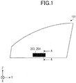
- FIG. 1 is a plan view of a window plate for vehicle according to an embodiment.
- FIG. 2 is a cross-sectional diagram of the window plate cut along a line A-A in FIG. 1 according to the embodiment.
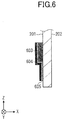
- FIGs. 3 to 6 are cross-sectional diagrams illustrating first to fourth variations of the embodiment.
- FIGs. 1 and 2 illustrate a window plate 101 that is a window plate for vehicle.
- a metallic member 204 is provided via a viscoelastic member 203.
- the window plate 101 includes a first surface 201, a second surface 202 opposing the first surface 201, and an end surface 209 that connects the first surface 201 with the second surface 202.
- the window plate 101 is provided with a member such as a holder at a lower side, and may be coupled to a lifting apparatus (not illustrated) and arranged so as to perform a lifting movement. Moreover, the lifting apparatus may not be provided, and the window plate 101 may be arranged so as to be fitted or engaged by a body flange.
- the metallic member 204 and the window plate 101 are electrically connected.
- the viscoelastic member 203 has conductivity, and thereby the electrical coupling of the metallic member 204 with the window plate 101 is enabled.
- the metallic member 204 can be used as a member for inhibiting vibration of the window plate 101, and at the same time, also can be used as a ground. Therefore, a window plate, in which electrostatic charges do not accumulate easily and noise is inhibited, can be provided.
- the viscoelastic member 203 and the metallic member 204 are arranged only in an inner region of the window plate 101.
- the inner region represents a region that does not include the end surface 209.
- the inner region is assumed to be a region that does not include the polished surface.
- other members required for lifting the window plate 101 may be arranged. Because the viscoelastic member 203 and the metallic member 204 are arranged only in the inner region, the end surface 209 allows for space savings.
- Elasticity of the viscoelastic member 203 is preferably 0.01 GPa or more but 1 GPa or less at a frequency of 100 Hz and temperature of 20 °C.
- the frequency of vibration of the window plate 101 and the frequency of vibration of the metallic member can be made different from each other, and noise can be inhibited effectively.
- Elasticity of the metallic member 204 is preferably 60 MPa or more but 80 MPa or less at a frequency of 100 Hz, and temperature of 20 °C. The vibration of the window plate 101 can be inhibited effectively.
- a thickness of the viscoelastic member 203 is preferably 0.5 mm or more but 3.0 mm or less, more preferably 0.7 mm or more but 2.8 mm or less, and further preferably 1 mm or more but 2.5 mm or less.
- the thickness is 0.5 mm or more, the vibration of the window plate 101 can be inhibited effectively.
- the thickness is 3.0 mm or less, accumulated electrostatic charges on the window plate 101 can be easily transferred to the metallic member 204.
- the "thickness" indicates a distance in the X-direction in the drawings.
- An area of the metallic member 204 is preferably 1000 mm 2 or more, and further preferably 2000 mm 2 or more. When the area is 1000 mm 2 or more, the metallic member 204 can sufficiently act as a ground for accumulated electrostatic charges on the window plate 101.
- a weight of the metallic member 204 is preferably 0.1 g or more, and more preferably 0.5 g or more. When the weight is 0.1 g or more, the metallic member 204 can inhibit the vibration of the window plate 101 effectively.
- FIG. 3 illustrates a first variation of the embodiment of the present invention.
- a viscoelastic member 303 and a metallic member 304 cover at least a part of an end portion of the window plate 101.
- the end portion of the window plate 101 includes a part of the first surface 201 near the end surface 209, a part of the second surface 202 near the end surface 209, and the end surface 209.
- the viscoelastic member 303 can contact the window plate 101 on the three surfaces.
- the vibration of the window plate 101 can be inhibited effectively.
- the viscoelastic member 303 and the metallic member 304 may be formed so as to cover the end portion of the window plate 101 with respect to at least a part of either of the sides of the window plate 101.
- a width of a part (gap) of the viscoelastic member 303 and the metallic member 304 that sandwiches the window plate 101 is preferably less than the thickness of the window plate 101. According to the above-described configuration, the viscoelastic member 303 is compressed when the window plate 101 is inserted, and thereby the vibration of the window plate 101 can be inhibited effectively.
- FIG. 4 illustrates a second variation of the embodiment of the present invention.
- a metallic member 404 covers at least a part of an end surface of a viscoelastic member 403, and contacts the window plate 101.
- the metallic member 404 and the window plate 101 are electrically connected, and thereby accumulated electrostatic charges on the window plate 101 become easily removed.
- the viscoelastic member 403 may not have conductivity. Therefore, for the viscoelastic member 403, the most suitable material for inhibiting the vibration of the window plate 101 can be used, and the material design becomes easier.
- the metallic member 404 has a form of covering the end surface of the viscoelastic member 403, because the structure is simple, it is easy to manufacture the window plate for vehicle.
- the metallic member 404 has a U-shape.
- the shape of the metallic member 404 is not limited to this, and may have, for example, an L-shape.
- the metallic member 404 may be provided with a protruding portion that protrudes in the thickness direction of the viscoelastic member 403 and contacts the window plate 101.
- An area of contact between the metallic member 404 the window plate 101 is preferably less than an area of contact between the viscoelastic member 403 the window plate 101.
- the contact area of the metallic member 404 is more preferably a half of the contact area of the viscoelastic member 403 or less, and further preferably one third of the contact area of the viscoelastic member 403 or less. According to the above-described configuration, a stable adhesion force between the viscoelastic member 403 and the window plate 101 can be ensured.
- the periphery of the region of contact between the metallic member 404 and the window plate 101 is preferably arranged relative to the area of contact between the viscoelastic member 403 and the window plate 101. Generation of noise by friction of the metallic member 404 with the window plate 101 can be inhibited.
- the term "periphery" represents one third or more of a perimeter of the region where the metallic member 404 contacts the window plate 101.
- FIG. 5 illustrates a third variation of the embodiment of the present invention.
- a metallic member 504 is joined to the window plate 101 via a conductive adhesion layer 505.
- the metallic member 504 and the window plate 101 are electrically connected, and thereby accumulated electrostatic charges on the window plate 101 become easily removed.
- the viscoelastic member 503 may not have conductivity. Therefore, for the viscoelastic member 503, the most suitable material for inhibiting the vibration of the window plate 101 can be used, and the material design becomes easier.
- an elasticity fraction defined by dividing the elasticity of the conductive adhesion layer 505 at a frequency of 100 Hz and at temperature of 20 °C by the elasticity of the viscoelastic member 503 at a frequency of 100 Hz and at temperature of 20 °C, is preferably 1.0 or more but 5.0 or less. According to the above-described configuration, the conductive adhesion layer 505 does not easily hinder the effect of inhibiting the vibration of the window plate 101.
- an area of adhesion between the conductive adhesion layer 505 and the window plate 101 is preferably less than an area of contact between the viscoelastic member 503 contacts the window plate 101.
- the contact area of the conductive adhesion layer 505 is more preferably a half of the contact area of the viscoelastic member 503 or less, and further preferably one third of the contact area of the viscoelastic member 503 or less. According to the above-described configuration, the conductive adhesion layer 505 does not easily hinder the effect of inhibiting the vibration of the window plate 101.
- FIG. 6 illustrates a fourth variation of the embodiment of the present invention.
- a region where a metallic member 604 is arranged on the window plate 101 via an elastic member 603 and a conductive adhesion layer 605, and a region where the metallic member 604 is arranged on the window plate 101 only via the conductive adhesion layer 605 are present.
- the region for inhibiting the vibration of the window plate 101 and the region for removing the electrostatic charge accumulated on the window plate 101 may be separately provided.
- Electrostatic charges may accumulate on a window plate due to friction against wind during the vehicle travelling, or friction against the lifting mechanism (sash part) during lifting.
- minute dirt particles such as sandy dust, easily adhere to the window plate, and the window plate easily becomes dirty.
- such a problem is not limited to a window plate, but the same problem arises in a resin plate that is a dielectric body.
- a window plate for vehicle in which electrostatic charges do not accumulate easily and which reduces noises, can be provided.
- the present invention can be preferably used as a window plate for vehicle, especially a window plate arranged in a window opening of a vehicle.
Landscapes
- Engineering & Computer Science (AREA)
- Mechanical Engineering (AREA)
- Physics & Mathematics (AREA)
- Acoustics & Sound (AREA)
- Multimedia (AREA)
- Window Of Vehicle (AREA)
Abstract
Description
- The disclosure herein generally relates to a window plate for vehicle.
- Conventionally, in order to reduce noise caused by vibration of a glass window during a vehicle travelling or the like, a door glass structure for vehicle having a lifting mechanism for glass window has been disclosed (See for example,
Japanese Unexamined Patent Application Publication No. 2002-321526 - It is a general object of at least one embodiment of the present invention to provide a window plate for vehicle that substantially obviates one or more problems caused by the limitations and disadvantages of the related art.
- In order to achieve the above-described purpose, the present invention provides a window plate for vehicle including a metallic member joined via a viscoelastic member on a surface of the window plate. The metallic member and the window plate are electrically connected.
- Other objects and further features of embodiments will become apparent from the following detailed description when read in conjunction with the accompanying drawings, in which:
-
FIG. 1 is a plan view depicting an example of a window plate for vehicle according to an embodiment; -
FIG. 2 is a cross-sectional diagram depicting an example of the window plate cut along a line A-A inFIG. 1 according to the embodiment; -
FIG. 3 is a cross-sectional diagram depicting an example of a window plate according to a first variation of the embodiment; -
FIG. 4 is a cross-sectional diagram depicting an example of a window plate according to a second variation of the embodiment; -
FIG. 5 is a cross-sectional diagram depicting an example of a window plate according to a third variation of the embodiment; and -
FIG. 6 is a cross-sectional diagram depicting an example of a window plate according to a fourth variation of the embodiment. - In the following, a window plate according to embodiments of the present invention will be described with reference to the accompanying drawings.
- Moreover, in the drawings for explaining configurations, coordinates are defined by arrows in the lower left part in each drawing. An explanation will be provided by using the coordinates as necessary. Moreover, in the specification, "X-direction" is assumed to indicate not only a direction from the tail of the arrow representing X-coordinates to the tip, but also a direction inverted by 180 degrees, from the tip to the tail. "Y-direction" and "Z-direction" are also assumed to indicate not only directions from the tails of the arrow representing Y-coordinates and Z-coordinates, respectively, to the tips, but also directions inverted by 180 degrees, respectively, from the tips to the tails. In the specification, the Z-direction and the Y-direction are also referred to as planar directions, and the X-direction is also referred to as a thickness direction.
- Moreover, in the specification, technical terms, such as "parallel" or "orthogonal", allow deviations sufficient keep the effect of the present invention. For example, errors of about ±5° are allowed from parallel or orthogonal positional relationships in a strict sense.
- Moreover, in the following, as an embodiment of the present invention, a case where the window plate for vehicle is a window plate will be described. However, the present invention is not limited to this. For example, the window plate for vehicle may be a transparent dielectric plate, such as a resin plate.
-
FIG. 1 is a plan view of a window plate for vehicle according to an embodiment.FIG. 2 is a cross-sectional diagram of the window plate cut along a line A-A inFIG. 1 according to the embodiment.FIGs. 3 to 6 are cross-sectional diagrams illustrating first to fourth variations of the embodiment. -
FIGs. 1 and2 illustrate awindow plate 101 that is a window plate for vehicle. On a surface of thewindow plate 101, ametallic member 204 is provided via aviscoelastic member 203. - The
window plate 101 includes afirst surface 201, asecond surface 202 opposing thefirst surface 201, and anend surface 209 that connects thefirst surface 201 with thesecond surface 202. - The
window plate 101 is provided with a member such as a holder at a lower side, and may be coupled to a lifting apparatus (not illustrated) and arranged so as to perform a lifting movement. Moreover, the lifting apparatus may not be provided, and thewindow plate 101 may be arranged so as to be fitted or engaged by a body flange. - The
metallic member 204 and thewindow plate 101 are electrically connected. In the embodiment illustrated inFIG. 2 , theviscoelastic member 203 has conductivity, and thereby the electrical coupling of themetallic member 204 with thewindow plate 101 is enabled. - According to the above-described configuration, the
metallic member 204 can be used as a member for inhibiting vibration of thewindow plate 101, and at the same time, also can be used as a ground. Therefore, a window plate, in which electrostatic charges do not accumulate easily and noise is inhibited, can be provided. - Moreover, the
viscoelastic member 203 and themetallic member 204 are arranged only in an inner region of thewindow plate 101. The inner region represents a region that does not include theend surface 209. When theend surface 209 is polished, the inner region is assumed to be a region that does not include the polished surface. On theend surface 209, other members required for lifting thewindow plate 101 may be arranged. Because theviscoelastic member 203 and themetallic member 204 are arranged only in the inner region, theend surface 209 allows for space savings. - Elasticity of the
viscoelastic member 203 is preferably 0.01 GPa or more but 1 GPa or less at a frequency of 100 Hz and temperature of 20 °C. The frequency of vibration of thewindow plate 101 and the frequency of vibration of the metallic member can be made different from each other, and noise can be inhibited effectively. - Elasticity of the
metallic member 204 is preferably 60 MPa or more but 80 MPa or less at a frequency of 100 Hz, and temperature of 20 °C. The vibration of thewindow plate 101 can be inhibited effectively. - A thickness of the
viscoelastic member 203 is preferably 0.5 mm or more but 3.0 mm or less, more preferably 0.7 mm or more but 2.8 mm or less, and further preferably 1 mm or more but 2.5 mm or less. When the thickness is 0.5 mm or more, the vibration of thewindow plate 101 can be inhibited effectively. Moreover, when the thickness is 3.0 mm or less, accumulated electrostatic charges on thewindow plate 101 can be easily transferred to themetallic member 204. Here, the "thickness" indicates a distance in the X-direction in the drawings. - An area of the
metallic member 204 is preferably 1000 mm2 or more, and further preferably 2000 mm2 or more. When the area is 1000 mm2 or more, themetallic member 204 can sufficiently act as a ground for accumulated electrostatic charges on thewindow plate 101. - A weight of the
metallic member 204 is preferably 0.1 g or more, and more preferably 0.5 g or more. When the weight is 0.1 g or more, themetallic member 204 can inhibit the vibration of thewindow plate 101 effectively. -
FIG. 3 illustrates a first variation of the embodiment of the present invention. InFIG. 3 , aviscoelastic member 303 and ametallic member 304 cover at least a part of an end portion of thewindow plate 101. - The end portion of the
window plate 101 includes a part of thefirst surface 201 near theend surface 209, a part of thesecond surface 202 near theend surface 209, and theend surface 209. - In this way, the
viscoelastic member 303 can contact thewindow plate 101 on the three surfaces. Thus, the vibration of thewindow plate 101 can be inhibited effectively. - The
viscoelastic member 303 and themetallic member 304 may be formed so as to cover the end portion of thewindow plate 101 with respect to at least a part of either of the sides of thewindow plate 101. - Moreover, in a state before the
window plate 101 is sandwiched by theviscoelastic member 303 and themetallic member 304, a width of a part (gap) of theviscoelastic member 303 and themetallic member 304 that sandwiches thewindow plate 101 is preferably less than the thickness of thewindow plate 101. According to the above-described configuration, theviscoelastic member 303 is compressed when thewindow plate 101 is inserted, and thereby the vibration of thewindow plate 101 can be inhibited effectively. -
FIG. 4 illustrates a second variation of the embodiment of the present invention. InFIG. 4 , ametallic member 404 covers at least a part of an end surface of aviscoelastic member 403, and contacts thewindow plate 101. - According to the above-described configuration, the
metallic member 404 and thewindow plate 101 are electrically connected, and thereby accumulated electrostatic charges on thewindow plate 101 become easily removed. Moreover, inFIG. 4 , theviscoelastic member 403 may not have conductivity. Therefore, for theviscoelastic member 403, the most suitable material for inhibiting the vibration of thewindow plate 101 can be used, and the material design becomes easier. - Moreover, when the
metallic member 404 has a form of covering the end surface of theviscoelastic member 403, because the structure is simple, it is easy to manufacture the window plate for vehicle. - In
FIG. 4 , themetallic member 404 has a U-shape. However, the shape of themetallic member 404 is not limited to this, and may have, for example, an L-shape. In this case, themetallic member 404 may be provided with a protruding portion that protrudes in the thickness direction of theviscoelastic member 403 and contacts thewindow plate 101. - An area of contact between the
metallic member 404 thewindow plate 101 is preferably less than an area of contact between theviscoelastic member 403 thewindow plate 101. The contact area of themetallic member 404 is more preferably a half of the contact area of theviscoelastic member 403 or less, and further preferably one third of the contact area of theviscoelastic member 403 or less. According to the above-described configuration, a stable adhesion force between theviscoelastic member 403 and thewindow plate 101 can be ensured. - Moreover, the periphery of the region of contact between the
metallic member 404 and thewindow plate 101 is preferably arranged relative to the area of contact between theviscoelastic member 403 and thewindow plate 101. Generation of noise by friction of themetallic member 404 with thewindow plate 101 can be inhibited. Here, the term "periphery" represents one third or more of a perimeter of the region where themetallic member 404 contacts thewindow plate 101. -
FIG. 5 illustrates a third variation of the embodiment of the present invention. InFIG. 5 , at least a part of ametallic member 504 is joined to thewindow plate 101 via aconductive adhesion layer 505. - According to the above-described configuration, the
metallic member 504 and thewindow plate 101 are electrically connected, and thereby accumulated electrostatic charges on thewindow plate 101 become easily removed. Moreover, inFIG. 5 , theviscoelastic member 503 may not have conductivity. Therefore, for theviscoelastic member 503, the most suitable material for inhibiting the vibration of thewindow plate 101 can be used, and the material design becomes easier. - Moreover, an elasticity fraction, defined by dividing the elasticity of the
conductive adhesion layer 505 at a frequency of 100 Hz and at temperature of 20 °C by the elasticity of theviscoelastic member 503 at a frequency of 100 Hz and at temperature of 20 °C, is preferably 1.0 or more but 5.0 or less. According to the above-described configuration, theconductive adhesion layer 505 does not easily hinder the effect of inhibiting the vibration of thewindow plate 101. - Moreover, an area of adhesion between the
conductive adhesion layer 505 and thewindow plate 101 is preferably less than an area of contact between theviscoelastic member 503 contacts thewindow plate 101. The contact area of theconductive adhesion layer 505 is more preferably a half of the contact area of theviscoelastic member 503 or less, and further preferably one third of the contact area of theviscoelastic member 503 or less. According to the above-described configuration, theconductive adhesion layer 505 does not easily hinder the effect of inhibiting the vibration of thewindow plate 101. -
FIG. 6 illustrates a fourth variation of the embodiment of the present invention. InFIG. 6 , a region where ametallic member 604 is arranged on thewindow plate 101 via anelastic member 603 and aconductive adhesion layer 605, and a region where themetallic member 604 is arranged on thewindow plate 101 only via theconductive adhesion layer 605 are present. In this way, the region for inhibiting the vibration of thewindow plate 101 and the region for removing the electrostatic charge accumulated on thewindow plate 101 may be separately provided. - Electrostatic charges may accumulate on a window plate due to friction against wind during the vehicle travelling, or friction against the lifting mechanism (sash part) during lifting. When electrostatic charges accumulate on the window plate, minute dirt particles, such as sandy dust, easily adhere to the window plate, and the window plate easily becomes dirty.
- Therefore, there has been a problem to reduce noise while solving the above-described problem. However, the door glass structure for vehicle disclosed in
Japanese Unexamined Patent Application Publication No. 2002-321526 - In addition, such a problem is not limited to a window plate, but the same problem arises in a resin plate that is a dielectric body.
- According to the present invention, a window plate for vehicle, in which electrostatic charges do not accumulate easily and which reduces noises, can be provided.
- Further, the present invention is not limited to these examples, but various variations and modifications may be made without deviating from the scope of the present invention.
- The present invention can be preferably used as a window plate for vehicle, especially a window plate arranged in a window opening of a vehicle.
- The present application is based on and claims the benefit of priority of
Japanese Priority Application No. 2016-058194 filed on March 23, 2016
Claims (8)
- A window plate for vehicle comprising:a metallic member joined via a viscoelastic member on a surface of the window plate, the metallic member and the window plate are electrically connected.
- The window plate for vehicle according to claim 1,
wherein the viscoelastic member has a conductivity. - The window plate for vehicle according to claim 1 or 2,
wherein the viscoelastic member and the metallic member cover at least a part of an end portion of the window plate. - The window plate for vehicle according to claim 1 or 2,
wherein the viscoelastic member and the metallic member are arranged only in an inner region of the window plate. - The window plate for vehicle according to any one of the preceding claims,
wherein the metallic member is provided with a protruding portion that protrudes from the metallic member in a thickness direction of the viscoelastic member, and
wherein the protruding portion contacts the window plate. - The window plate for vehicle according to any one of the preceding claims,
wherein the metallic member covers at least a part of an end portion of the viscoelastic member, and contacts the window plate. - The window plate for vehicle according to any one of the preceding claims,
wherein at least a part of the metallic member is joined to the window plate via a conductive adhesion layer. - The window plate for vehicle according to claim 7,
wherein an elasticity fraction, defined by dividing elasticity of the conductive adhesion layer at a frequency of 100 Hz and at temperature of 20 °C by elasticity of the viscoelastic member at a frequency of 100 Hz and at temperature of 20 °C, is 1.0 or more but 5.0 or less.
Applications Claiming Priority (1)
| Application Number | Priority Date | Filing Date | Title |
|---|---|---|---|
| JP2016058194A JP6665618B2 (en) | 2016-03-23 | 2016-03-23 | Vehicle window boards |
Publications (2)
| Publication Number | Publication Date |
|---|---|
| EP3222451A1 true EP3222451A1 (en) | 2017-09-27 |
| EP3222451B1 EP3222451B1 (en) | 2019-03-06 |
Family
ID=58358368
Family Applications (1)
| Application Number | Title | Priority Date | Filing Date |
|---|---|---|---|
| EP17160761.7A Active EP3222451B1 (en) | 2016-03-23 | 2017-03-14 | Window plate for vehicle |
Country Status (4)
| Country | Link |
|---|---|
| US (1) | US20170274740A1 (en) |
| EP (1) | EP3222451B1 (en) |
| JP (1) | JP6665618B2 (en) |
| CN (1) | CN107225939A (en) |
Families Citing this family (3)
| Publication number | Priority date | Publication date | Assignee | Title |
|---|---|---|---|---|
| JP7058068B2 (en) * | 2016-06-03 | 2022-04-21 | Agc株式会社 | Car door |
| DE112017005054T5 (en) * | 2016-10-05 | 2019-06-19 | AGC Inc. | Sound-absorbing structure of a belt line part of a vehicle and vehicle window pane |
| WO2019009156A1 (en) * | 2017-07-03 | 2019-01-10 | Agc株式会社 | Automobile belt line part sound insulation structure and automobile door glass |
Citations (2)
| Publication number | Priority date | Publication date | Assignee | Title |
|---|---|---|---|---|
| JP2002321526A (en) | 2001-04-26 | 2002-11-05 | Nippon Sheet Glass Co Ltd | Door glass structure for vehicle |
| DE102009020351A1 (en) * | 2009-05-07 | 2010-11-11 | Dr. Ing. H.C. F. Porsche Aktiengesellschaft | Windowpane, particularly height-adjustable side windowpane for motor vehicle, has vibration-reducing element which is formed as aluminum-butyl foil applied on vehicle windowpane |
Family Cites Families (7)
| Publication number | Priority date | Publication date | Assignee | Title |
|---|---|---|---|---|
| US4864786A (en) * | 1987-12-28 | 1989-09-12 | Ford Motor Company | Tolerance compensating clip |
| CN2322965Y (en) * | 1998-05-14 | 1999-06-09 | 王斌 | Electronic secrecy glass for window type shield room |
| US6748638B2 (en) * | 2002-04-15 | 2004-06-15 | Dura Global Technologies, Inc. | Apparatus and method for locating a vehicle window panel |
| FR2877881B1 (en) * | 2004-11-16 | 2009-10-02 | Renault Sas | VEHICLE COMPRISING A GLASS FITTED TO THE BODY |
| FR2914589B1 (en) * | 2007-04-06 | 2009-09-04 | Saint Gobain | GLAZING WITH IMPROVED VIBRO-ACOUSTIC DAMPENING, METHOD FOR PRODUCING SUCH GLAZING AND METHOD FOR ACOUSTIC PROTECTION IN VEHICLE CABINET |
| DE102007046320A1 (en) * | 2007-09-27 | 2009-04-02 | Robert Bosch Gmbh | Contacting arrangement and contacting method for tracks of heaters and antennas in vehicle windows |
| JPWO2016190119A1 (en) * | 2015-05-26 | 2018-03-15 | 旭硝子株式会社 | Window plate with damping member and damping member |
-
2016
- 2016-03-23 JP JP2016058194A patent/JP6665618B2/en active Active
-
2017
- 2017-03-07 US US15/452,216 patent/US20170274740A1/en not_active Abandoned
- 2017-03-14 EP EP17160761.7A patent/EP3222451B1/en active Active
- 2017-03-21 CN CN201710168995.6A patent/CN107225939A/en active Pending
Patent Citations (2)
| Publication number | Priority date | Publication date | Assignee | Title |
|---|---|---|---|---|
| JP2002321526A (en) | 2001-04-26 | 2002-11-05 | Nippon Sheet Glass Co Ltd | Door glass structure for vehicle |
| DE102009020351A1 (en) * | 2009-05-07 | 2010-11-11 | Dr. Ing. H.C. F. Porsche Aktiengesellschaft | Windowpane, particularly height-adjustable side windowpane for motor vehicle, has vibration-reducing element which is formed as aluminum-butyl foil applied on vehicle windowpane |
Also Published As
| Publication number | Publication date |
|---|---|
| US20170274740A1 (en) | 2017-09-28 |
| EP3222451B1 (en) | 2019-03-06 |
| JP6665618B2 (en) | 2020-03-13 |
| JP2017171072A (en) | 2017-09-28 |
| CN107225939A (en) | 2017-10-03 |
Similar Documents
| Publication | Publication Date | Title |
|---|---|---|
| KR102089489B1 (en) | Folding terminal | |
| EP3222451A1 (en) | Window plate for vehicle | |
| US10461478B2 (en) | Connector having shell and connector device | |
| US10522950B2 (en) | Connector including shell having lock mechanism and connector device | |
| EP2706429A3 (en) | Dock with compliant connector mount | |
| US10165672B2 (en) | Shielding clip and electronic device | |
| EP3108547A1 (en) | Contact element comprising a looped spring portion | |
| JP2015023140A (en) | Lid structure and electronic equipment | |
| EP2795735B1 (en) | Electrical connector, its assembly and its method of manufacture | |
| CN204180435U (en) | Electronic equipment | |
| CN107148707B (en) | Electric connection box | |
| CN210779068U (en) | Floating bus connecting assembly | |
| EP3018666A2 (en) | Holder and noise current absorber | |
| TWI598021B (en) | Electronic device and hinge assembly thereof | |
| US9291482B2 (en) | Linear encoder | |
| JP6681549B2 (en) | Electronic device including a battery and a battery mounting portion | |
| KR19990016398A (en) | Electronic Gasket Device | |
| CN208994355U (en) | A container door assembly and a container including the same | |
| JPWO2017146082A1 (en) | Power supply system | |
| JPH0278296A (en) | Electromagnetic shielding device of electronic equipment casing | |
| CN209813914U (en) | A position-limiting structure and a safety belt fastening device | |
| CN219134330U (en) | Charging port cover for vehicle and vehicle | |
| JP5953594B2 (en) | Conductive spacer | |
| CN211592994U (en) | Base station for mooring unmanned aerial vehicle with clamping assembly and unmanned aerial vehicle system | |
| CN210668819U (en) | connection interface |
Legal Events
| Date | Code | Title | Description |
|---|---|---|---|
| PUAI | Public reference made under article 153(3) epc to a published international application that has entered the european phase |
Free format text: ORIGINAL CODE: 0009012 |
|
| STAA | Information on the status of an ep patent application or granted ep patent |
Free format text: STATUS: THE APPLICATION HAS BEEN PUBLISHED |
|
| AK | Designated contracting states |
Kind code of ref document: A1 Designated state(s): AL AT BE BG CH CY CZ DE DK EE ES FI FR GB GR HR HU IE IS IT LI LT LU LV MC MK MT NL NO PL PT RO RS SE SI SK SM TR |
|
| AX | Request for extension of the european patent |
Extension state: BA ME |
|
| STAA | Information on the status of an ep patent application or granted ep patent |
Free format text: STATUS: REQUEST FOR EXAMINATION WAS MADE |
|
| 17P | Request for examination filed |
Effective date: 20171123 |
|
| RBV | Designated contracting states (corrected) |
Designated state(s): AL AT BE BG CH CY CZ DE DK EE ES FI FR GB GR HR HU IE IS IT LI LT LU LV MC MK MT NL NO PL PT RO RS SE SI SK SM TR |
|
| RIC1 | Information provided on ipc code assigned before grant |
Ipc: B32B 17/06 20060101ALI20180103BHEP Ipc: B60J 1/20 20060101AFI20180103BHEP |
|
| STAA | Information on the status of an ep patent application or granted ep patent |
Free format text: STATUS: EXAMINATION IS IN PROGRESS |
|
| 17Q | First examination report despatched |
Effective date: 20180226 |
|
| RAP1 | Party data changed (applicant data changed or rights of an application transferred) |
Owner name: AGC INC. |
|
| GRAP | Despatch of communication of intention to grant a patent |
Free format text: ORIGINAL CODE: EPIDOSNIGR1 |
|
| STAA | Information on the status of an ep patent application or granted ep patent |
Free format text: STATUS: GRANT OF PATENT IS INTENDED |
|
| INTG | Intention to grant announced |
Effective date: 20181018 |
|
| GRAS | Grant fee paid |
Free format text: ORIGINAL CODE: EPIDOSNIGR3 |
|
| GRAA | (expected) grant |
Free format text: ORIGINAL CODE: 0009210 |
|
| STAA | Information on the status of an ep patent application or granted ep patent |
Free format text: STATUS: THE PATENT HAS BEEN GRANTED |
|
| AK | Designated contracting states |
Kind code of ref document: B1 Designated state(s): AL AT BE BG CH CY CZ DE DK EE ES FI FR GB GR HR HU IE IS IT LI LT LU LV MC MK MT NL NO PL PT RO RS SE SI SK SM TR |
|
| REG | Reference to a national code |
Ref country code: GB Ref legal event code: FG4D |
|
| REG | Reference to a national code |
Ref country code: CH Ref legal event code: EP Ref country code: AT Ref legal event code: REF Ref document number: 1104057 Country of ref document: AT Kind code of ref document: T Effective date: 20190315 |
|
| REG | Reference to a national code |
Ref country code: DE Ref legal event code: R096 Ref document number: 602017002425 Country of ref document: DE |
|
| REG | Reference to a national code |
Ref country code: IE Ref legal event code: FG4D |
|
| REG | Reference to a national code |
Ref country code: NL Ref legal event code: MP Effective date: 20190306 |
|
| REG | Reference to a national code |
Ref country code: LT Ref legal event code: MG4D |
|
| PG25 | Lapsed in a contracting state [announced via postgrant information from national office to epo] |
Ref country code: SE Free format text: LAPSE BECAUSE OF FAILURE TO SUBMIT A TRANSLATION OF THE DESCRIPTION OR TO PAY THE FEE WITHIN THE PRESCRIBED TIME-LIMIT Effective date: 20190306 Ref country code: ES Free format text: LAPSE BECAUSE OF FAILURE TO SUBMIT A TRANSLATION OF THE DESCRIPTION OR TO PAY THE FEE WITHIN THE PRESCRIBED TIME-LIMIT Effective date: 20190306 Ref country code: LT Free format text: LAPSE BECAUSE OF FAILURE TO SUBMIT A TRANSLATION OF THE DESCRIPTION OR TO PAY THE FEE WITHIN THE PRESCRIBED TIME-LIMIT Effective date: 20190306 Ref country code: NO Free format text: LAPSE BECAUSE OF FAILURE TO SUBMIT A TRANSLATION OF THE DESCRIPTION OR TO PAY THE FEE WITHIN THE PRESCRIBED TIME-LIMIT Effective date: 20190606 Ref country code: FI Free format text: LAPSE BECAUSE OF FAILURE TO SUBMIT A TRANSLATION OF THE DESCRIPTION OR TO PAY THE FEE WITHIN THE PRESCRIBED TIME-LIMIT Effective date: 20190306 |
|
| PG25 | Lapsed in a contracting state [announced via postgrant information from national office to epo] |
Ref country code: BG Free format text: LAPSE BECAUSE OF FAILURE TO SUBMIT A TRANSLATION OF THE DESCRIPTION OR TO PAY THE FEE WITHIN THE PRESCRIBED TIME-LIMIT Effective date: 20190606 Ref country code: LV Free format text: LAPSE BECAUSE OF FAILURE TO SUBMIT A TRANSLATION OF THE DESCRIPTION OR TO PAY THE FEE WITHIN THE PRESCRIBED TIME-LIMIT Effective date: 20190306 Ref country code: RS Free format text: LAPSE BECAUSE OF FAILURE TO SUBMIT A TRANSLATION OF THE DESCRIPTION OR TO PAY THE FEE WITHIN THE PRESCRIBED TIME-LIMIT Effective date: 20190306 Ref country code: HR Free format text: LAPSE BECAUSE OF FAILURE TO SUBMIT A TRANSLATION OF THE DESCRIPTION OR TO PAY THE FEE WITHIN THE PRESCRIBED TIME-LIMIT Effective date: 20190306 Ref country code: GR Free format text: LAPSE BECAUSE OF FAILURE TO SUBMIT A TRANSLATION OF THE DESCRIPTION OR TO PAY THE FEE WITHIN THE PRESCRIBED TIME-LIMIT Effective date: 20190607 Ref country code: NL Free format text: LAPSE BECAUSE OF FAILURE TO SUBMIT A TRANSLATION OF THE DESCRIPTION OR TO PAY THE FEE WITHIN THE PRESCRIBED TIME-LIMIT Effective date: 20190306 |
|
| REG | Reference to a national code |
Ref country code: AT Ref legal event code: MK05 Ref document number: 1104057 Country of ref document: AT Kind code of ref document: T Effective date: 20190306 |
|
| PG25 | Lapsed in a contracting state [announced via postgrant information from national office to epo] |
Ref country code: PT Free format text: LAPSE BECAUSE OF FAILURE TO SUBMIT A TRANSLATION OF THE DESCRIPTION OR TO PAY THE FEE WITHIN THE PRESCRIBED TIME-LIMIT Effective date: 20190706 Ref country code: AL Free format text: LAPSE BECAUSE OF FAILURE TO SUBMIT A TRANSLATION OF THE DESCRIPTION OR TO PAY THE FEE WITHIN THE PRESCRIBED TIME-LIMIT Effective date: 20190306 Ref country code: SK Free format text: LAPSE BECAUSE OF FAILURE TO SUBMIT A TRANSLATION OF THE DESCRIPTION OR TO PAY THE FEE WITHIN THE PRESCRIBED TIME-LIMIT Effective date: 20190306 Ref country code: IT Free format text: LAPSE BECAUSE OF FAILURE TO SUBMIT A TRANSLATION OF THE DESCRIPTION OR TO PAY THE FEE WITHIN THE PRESCRIBED TIME-LIMIT Effective date: 20190306 Ref country code: CZ Free format text: LAPSE BECAUSE OF FAILURE TO SUBMIT A TRANSLATION OF THE DESCRIPTION OR TO PAY THE FEE WITHIN THE PRESCRIBED TIME-LIMIT Effective date: 20190306 Ref country code: RO Free format text: LAPSE BECAUSE OF FAILURE TO SUBMIT A TRANSLATION OF THE DESCRIPTION OR TO PAY THE FEE WITHIN THE PRESCRIBED TIME-LIMIT Effective date: 20190306 Ref country code: EE Free format text: LAPSE BECAUSE OF FAILURE TO SUBMIT A TRANSLATION OF THE DESCRIPTION OR TO PAY THE FEE WITHIN THE PRESCRIBED TIME-LIMIT Effective date: 20190306 |
|
| PG25 | Lapsed in a contracting state [announced via postgrant information from national office to epo] |
Ref country code: PL Free format text: LAPSE BECAUSE OF FAILURE TO SUBMIT A TRANSLATION OF THE DESCRIPTION OR TO PAY THE FEE WITHIN THE PRESCRIBED TIME-LIMIT Effective date: 20190306 Ref country code: LU Free format text: LAPSE BECAUSE OF NON-PAYMENT OF DUE FEES Effective date: 20190314 Ref country code: SM Free format text: LAPSE BECAUSE OF FAILURE TO SUBMIT A TRANSLATION OF THE DESCRIPTION OR TO PAY THE FEE WITHIN THE PRESCRIBED TIME-LIMIT Effective date: 20190306 |
|
| REG | Reference to a national code |
Ref country code: DE Ref legal event code: R097 Ref document number: 602017002425 Country of ref document: DE |
|
| REG | Reference to a national code |
Ref country code: BE Ref legal event code: MM Effective date: 20190331 |
|
| PG25 | Lapsed in a contracting state [announced via postgrant information from national office to epo] |
Ref country code: IS Free format text: LAPSE BECAUSE OF FAILURE TO SUBMIT A TRANSLATION OF THE DESCRIPTION OR TO PAY THE FEE WITHIN THE PRESCRIBED TIME-LIMIT Effective date: 20190706 Ref country code: AT Free format text: LAPSE BECAUSE OF FAILURE TO SUBMIT A TRANSLATION OF THE DESCRIPTION OR TO PAY THE FEE WITHIN THE PRESCRIBED TIME-LIMIT Effective date: 20190306 |
|
| PLBE | No opposition filed within time limit |
Free format text: ORIGINAL CODE: 0009261 |
|
| STAA | Information on the status of an ep patent application or granted ep patent |
Free format text: STATUS: NO OPPOSITION FILED WITHIN TIME LIMIT |
|
| PG25 | Lapsed in a contracting state [announced via postgrant information from national office to epo] |
Ref country code: MC Free format text: LAPSE BECAUSE OF FAILURE TO SUBMIT A TRANSLATION OF THE DESCRIPTION OR TO PAY THE FEE WITHIN THE PRESCRIBED TIME-LIMIT Effective date: 20190306 Ref country code: DK Free format text: LAPSE BECAUSE OF FAILURE TO SUBMIT A TRANSLATION OF THE DESCRIPTION OR TO PAY THE FEE WITHIN THE PRESCRIBED TIME-LIMIT Effective date: 20190306 Ref country code: IE Free format text: LAPSE BECAUSE OF NON-PAYMENT OF DUE FEES Effective date: 20190314 |
|
| 26N | No opposition filed |
Effective date: 20191209 |
|
| PG25 | Lapsed in a contracting state [announced via postgrant information from national office to epo] |
Ref country code: SI Free format text: LAPSE BECAUSE OF FAILURE TO SUBMIT A TRANSLATION OF THE DESCRIPTION OR TO PAY THE FEE WITHIN THE PRESCRIBED TIME-LIMIT Effective date: 20190306 Ref country code: BE Free format text: LAPSE BECAUSE OF NON-PAYMENT OF DUE FEES Effective date: 20190331 |
|
| PG25 | Lapsed in a contracting state [announced via postgrant information from national office to epo] |
Ref country code: TR Free format text: LAPSE BECAUSE OF FAILURE TO SUBMIT A TRANSLATION OF THE DESCRIPTION OR TO PAY THE FEE WITHIN THE PRESCRIBED TIME-LIMIT Effective date: 20190306 |
|
| PG25 | Lapsed in a contracting state [announced via postgrant information from national office to epo] |
Ref country code: MT Free format text: LAPSE BECAUSE OF NON-PAYMENT OF DUE FEES Effective date: 20190314 Ref country code: FR Free format text: LAPSE BECAUSE OF NON-PAYMENT OF DUE FEES Effective date: 20190506 |
|
| REG | Reference to a national code |
Ref country code: CH Ref legal event code: PL |
|
| PG25 | Lapsed in a contracting state [announced via postgrant information from national office to epo] |
Ref country code: CH Free format text: LAPSE BECAUSE OF NON-PAYMENT OF DUE FEES Effective date: 20200331 Ref country code: LI Free format text: LAPSE BECAUSE OF NON-PAYMENT OF DUE FEES Effective date: 20200331 |
|
| PG25 | Lapsed in a contracting state [announced via postgrant information from national office to epo] |
Ref country code: CY Free format text: LAPSE BECAUSE OF FAILURE TO SUBMIT A TRANSLATION OF THE DESCRIPTION OR TO PAY THE FEE WITHIN THE PRESCRIBED TIME-LIMIT Effective date: 20190306 |
|
| PG25 | Lapsed in a contracting state [announced via postgrant information from national office to epo] |
Ref country code: HU Free format text: LAPSE BECAUSE OF FAILURE TO SUBMIT A TRANSLATION OF THE DESCRIPTION OR TO PAY THE FEE WITHIN THE PRESCRIBED TIME-LIMIT; INVALID AB INITIO Effective date: 20170314 |
|
| GBPC | Gb: european patent ceased through non-payment of renewal fee |
Effective date: 20210314 |
|
| PG25 | Lapsed in a contracting state [announced via postgrant information from national office to epo] |
Ref country code: GB Free format text: LAPSE BECAUSE OF NON-PAYMENT OF DUE FEES Effective date: 20210314 |
|
| PG25 | Lapsed in a contracting state [announced via postgrant information from national office to epo] |
Ref country code: MK Free format text: LAPSE BECAUSE OF FAILURE TO SUBMIT A TRANSLATION OF THE DESCRIPTION OR TO PAY THE FEE WITHIN THE PRESCRIBED TIME-LIMIT Effective date: 20190306 |
|
| PGFP | Annual fee paid to national office [announced via postgrant information from national office to epo] |
Ref country code: DE Payment date: 20260319 Year of fee payment: 10 |