EP3222441A1 - Stud and studdable tire - Google Patents
Stud and studdable tire Download PDFInfo
- Publication number
- EP3222441A1 EP3222441A1 EP15860521.2A EP15860521A EP3222441A1 EP 3222441 A1 EP3222441 A1 EP 3222441A1 EP 15860521 A EP15860521 A EP 15860521A EP 3222441 A1 EP3222441 A1 EP 3222441A1
- Authority
- EP
- European Patent Office
- Prior art keywords
- stud
- central axis
- section
- curved
- portions
- Prior art date
- Legal status (The legal status is an assumption and is not a legal conclusion. Google has not performed a legal analysis and makes no representation as to the accuracy of the status listed.)
- Granted
Links
- 230000002093 peripheral effect Effects 0.000 claims abstract description 105
- 230000001133 acceleration Effects 0.000 abstract description 28
- 230000000694 effects Effects 0.000 abstract description 25
- 230000001976 improved effect Effects 0.000 description 22
- 238000005096 rolling process Methods 0.000 description 7
- 230000009466 transformation Effects 0.000 description 5
- 239000011324 bead Substances 0.000 description 4
- 230000001419 dependent effect Effects 0.000 description 4
- 238000005336 cracking Methods 0.000 description 3
- 230000000994 depressogenic effect Effects 0.000 description 2
- 239000000835 fiber Substances 0.000 description 2
- 239000000843 powder Substances 0.000 description 2
- 229910000831 Steel Inorganic materials 0.000 description 1
- 238000009825 accumulation Methods 0.000 description 1
- 230000007423 decrease Effects 0.000 description 1
- 230000003247 decreasing effect Effects 0.000 description 1
- 238000006748 scratching Methods 0.000 description 1
- 230000002393 scratching effect Effects 0.000 description 1
- 239000010959 steel Substances 0.000 description 1
Images





Classifications
-
- B—PERFORMING OPERATIONS; TRANSPORTING
- B60—VEHICLES IN GENERAL
- B60C—VEHICLE TYRES; TYRE INFLATION; TYRE CHANGING; CONNECTING VALVES TO INFLATABLE ELASTIC BODIES IN GENERAL; DEVICES OR ARRANGEMENTS RELATED TO TYRES
- B60C11/00—Tyre tread bands; Tread patterns; Anti-skid inserts
- B60C11/14—Anti-skid inserts, e.g. vulcanised into the tread band
- B60C11/16—Anti-skid inserts, e.g. vulcanised into the tread band of plug form, e.g. made from metal, textile
-
- B—PERFORMING OPERATIONS; TRANSPORTING
- B60—VEHICLES IN GENERAL
- B60C—VEHICLE TYRES; TYRE INFLATION; TYRE CHANGING; CONNECTING VALVES TO INFLATABLE ELASTIC BODIES IN GENERAL; DEVICES OR ARRANGEMENTS RELATED TO TYRES
- B60C11/00—Tyre tread bands; Tread patterns; Anti-skid inserts
- B60C11/14—Anti-skid inserts, e.g. vulcanised into the tread band
- B60C11/16—Anti-skid inserts, e.g. vulcanised into the tread band of plug form, e.g. made from metal, textile
- B60C11/1675—Anti-skid inserts, e.g. vulcanised into the tread band of plug form, e.g. made from metal, textile with special shape of the plug- tip
Definitions
- the present invention relates to a stud for a studdable tire (hereinafter referred to simply as "stud") and a studdable tire having the studs fitted thereon.
- stud a studdable tire
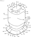
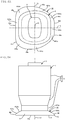
- a stud 100 is formed into a columnar body along a central axis 100C, with a body section 120, a pin section 130 disposed on one end of the body section along the central axis 100C, and a flange section 140 disposed on the other end of the body section along the central axis 100C.
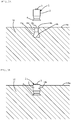
- the stud 100 is embedded in the tread surface of a tire with the flange section 140 first fitted into a stud recess (hole) formed in the tread surface in such a manner that the pin section 130 protrudes from the tread surface 140 (see FIG. 14 ).
- the stud 100 known in the art has the body section 120, the pin section 130, and the flange section 140, and is formed such that the sectional shape orthogonal to the central axis 100C is circular.
- the central axis 100C refers to the axis of rotation center of the pin section, the body section, and the flange section of a stud embedded in the direction of tire radius (depth direction), that is, the axis of the median point in the cross section orthogonal to the tire radial direction.
- the stud 100 is formed in a cylindrical shape with the body section 120 and the pin section 130 extending in the direction along the central axis 100C. And formed on one end (end surface) of the pin section 130 are grooves 132 in a cross shape in planar view extending in directions orthogonal to the central axis 100C.
- FIG. 14 shows how a stud 100 fitted in the stud recess formed in the tread surface of a studdable tire falls off from a worn tread surface at a sudden starting or acceleration of the vehicle.
- W stands for the direction of the rolling motion of the studdable tire 150
- F the leading-end side where the studdable tire 150 in the rolling motion first touches the ground
- R the trailing-end side where the studdable tire 150 in the rolling motion touches the ground later.
- the studdable tire 150 is required of having the durability performance of the pin section 130, the edge performance of the pin section 130 to scratch the ice on the road surface, and the anti-stud-loss performance to resist the falling out of the studs 100.
- a stud 100 formed in an elliptical cylinder shape (see Patent Document 1) .
- the stud consists of a body section, a pin section disposed on one end of the body section along the central axis of the body section, and a flange section disposed on the other end of the body section along the central axis.
- the stud is embedded in the tread surface of a tire with the flange section first fitted into a stud recess formed in the tread surface in such a manner that the pin section protrudes from the tread surface.
- Patent Document 1 Japanese Patent No. 4088055
- the stud disclosed in Patent Document 1 has an elliptically shaped peripheral edge at the end of the pin section.
- the stud is prone to damage to the pin section at the time of braking or acceleration due to the insufficient strength in the end portions of the major axis of the elliptical shape.
- the use of simply circular or elliptical shape has not ensured sufficient edge effect or anti-stud-loss performance.
- the present invention aims to provide a stud featuring excellent braking and acceleration performance due to high edge effect, improved anti-stud-loss performance, and high durability of the pin section having strength to resist damage thereto, and a studdable tire fitted with such studs.
- a stud including a body section in a columnar shape, a pin section disposed on one end of the body section along the central axis thereof, and a flange section disposed on the other end of the body section along the central axis thereof.
- the pin section of the stud has a pair of straight edge portions defined by the peripheral edges at one end thereof along the central axis, or the peripheral profile lines in the cross section orthogonal to the central axis, opposite each other with the central axis therebetween, a pair of curved edge portions extending from the ends of the pair of straight edge portions and outwardly bulging away from each other with the central axis therebetween, and curved border edge portions between the straight edge portions and the curved edge portions outwardly bulging away from the central axis.
- a stud 1 which is comprised of a body section 2, a pin section 3 disposed on one end of the body section 2 along the central axis of the body section 2, and a flange section 4 disposed on the other end along the central axis of the body section 2, is a columnar member extending along the central axis of the body section 2.
- the stud 1 according to the first embodiment is formed with the central axis of the body section 2 in line (continuous straight line) with the central axis of the pin section 3 and the central axis of the flange section 4. And the continuous straight line constitutes the central axis 1C of the stud 1 (hereinafter referred to simply as "central axis 1C").
- the central axis 1C refers to the axis of rotation center of the pin section, the body section, and the flange section of a stud embedded in the direction of tire radius (depth direction), that is, the axis of the median point in the cross section orthogonal to the tire radial direction.
- the central axis 1C is the central axis extending in the direction of extension of the stud 1 positioned at the median point in the cross section orthogonal to the direction of extension of the stud 1 embedded in a tire.
- the stud 1 is embedded in the surface 14a side of the tread 14 of a tire with the flange section 4 first fitted into a stud recess 14b (see FIG. 3 ) formed in the tread surface 14a.
- a studdable tire (studded tire) 10 is formed with the pin section 3, which is one end of the stud 1, protruding from the surface 14a side of the tread 14.
- the body section 2 has an upper part 2A located on one end along the central axis 1C, a lower part 2B located on the other end along the central axis 1C, and a middle part 2C connecting the upper part 2A and the lower part 2B.
- the upper part 2A is formed in a columnar body in the same shape in cross section orthogonal to the central axis 1C for the whole length along the central axis 1C.
- the lower part 2B is formed in a columnar body in the same shape in cross section orthogonal to the central axis 1C for the whole length along the central axis 1C.
- sectional diameter (axis length) of the upper part 2A and the sectional diameter of the lower part 2B are in a relationship of "sectional diameter of the upper part 2A > sectional diameter of the lower part 2B".
- the middle part 2C is formed in a cone-shaped columnar body whose sectional diameter orthogonal to the central axis 1C reduces gradually from the upper part 2A side to the lower part 2B side.
- the outer periphery of the body section 2 consists of a pair of flat surface portions 21A, 22A opposite each other with the central axis 1C therebetween, a pair of curved surface portions 23A, 24A extending from the ends of the pair of flat surface portions 21A, 22A and outwardly bulging opposite each other with the central axis 1C therebetween, and curved border surface portions 25A, 26A, 27A, 28A, which are border portions between the flat surface portions 21A, 22A and the curved surface portions 23A, 24A outwardly bulging away from the central axis 1C.
- the outer periphery of the body section 2 is formed with one end of the curved surface portion 23A, which is one of the pair of curved surface portions 23A, 24A, connected with one end of the flat surface portion 21A, which is one of the pair of flat surface portions 21A, 22A, via the curved border surface portion 25A, the other end of one curved surface portion 23A connected with one end of the other flat surface portion 22A via the curved border surface portion 26A, one end of the other curved surface portion 24A connected with the other end of one flat surface portion 21A via the curved border surface portion 27A, and the other end of the other curved surface portion 24A connected with the other end of the other flat surface portion 22A via the curved border surface portion 28A.
- the curved border surface portions are each connected with a flat surface portion at one end and with a curved surface portion at the other end.
- the curved surface portions 23A, 24A may each be of a constitution combining a curved surface portion and a flat surface portion.
- the outer periphery of the body section 2 refers to the peripheral side surfaces extending in the same direction as the central axis 1C.
- the outer periphery of the body section 2 is the surface extending along the central axis 1C and surrounding the central axis.
- the body section 2 is the most preferably of a constitution having a pair of straight edge portions 21, 22 defined by peripheral profile lines of the cross section orthogonal to the central axis 1C and the peripheral edges (edges) at one end along the central axis 1C (hereinafter referred to as "end surface 2t") opposite each other with the central axis 1C therebetween, a pair of curved edge portions 23, 24 extending from the ends of the pair of straight edge portions 21, 22 and outwardly bulging opposite each other with the central axis 1C therebetween, and curved border edge portions 25, 26, 27, 28, which are border portions between the straight edge portions 21, 22 and the curved edge portions 23, 24 outwardly bulging away from the central axis 1C.
- the curved border edge portions are each connected to a straight edge portion at one end and to a curved edge portion at the other end.
- curved edge portions 23, 24 may each be configured by a combination of a curved edge portion and a straight edge portion.
- the end surface 2t of the body section 2 is formed into a flat surface orthogonal to the central axis 1C or a curved surface bulging toward one end thereof along the central axis 1C or a curved surface depressed toward the other end thereof along the central axis 1C, for instance.
- the pair of flat surface portions 21A, 22A constituting the outer periphery of the upper part 2A are formed by parallel flat surfaces opposite each other with the central axis 1C therebetween.
- the pair of curved surface portions 23A, 24A constituting the outer periphery of the upper part 2A are formed by curved surfaces having the same curvature and the same distance to the central axis 1C.
- the length of the pair of flat surface portions 21A, 22A constituting the outer periphery of the upper part 2A in the plane orthogonal to the central axis 1C (that is, the length of the straight line intersecting the plane orthogonal to the central axis 1C on the pair of flat surface portions 21A, 22A of the upper part 2A (hereinafter referred to as "width length")) is the same as the length of each of the straight edge portions 21, 22.
- the length of the pair of curved surface portions 23A, 24A of the upper part 2A in the plane orthogonal to the central axis 1C (that is, the length of the curved line intersecting the plane orthogonal to the central axis 1C on the pair of curved surface portions 23A, 24A of the upper part 2A (hereinafter referred to as "width length")) is the same as the length of each of the curved edge portions 23, 24.
- the shape of the peripheral edges (edges) of the end surface 2t of the upper part 2A is congruent to the shape of the peripheral profile lines of the cross section of the upper part 2A orthogonal to the central axis 1C.
- the pair of flat surface portions 21A, 22A constituting the outer periphery of the lower part 2B are formed by parallel flat surfaces opposite each other with the central axis 1C therebetween.
- the pair of curved surface portions 23A, 24A constituting the outer periphery of the lower part 2B are formed by curved surfaces having the same curvature and the same distance to the central axis 1C.
- the width length of the pair of flat surface portions 21A, 22A of the lower part 2B is the same as the length of each of the straight edge portions 21, 22.
- the width length of the pair of curved surface portions 23A, 24A of the lower part 2B is the same as the length of each of the curved edge portions 23, 24.
- the pair of flat surface portions 21A, 22A constituting the outer periphery of the middle part 2C are formed by flat surfaces opposite each other with the central axis 1C therebetween with reducing distance between the opposite surfaces from the upper part 2A side to the lower part 2B side.
- the pair of curved surface portions 23A, 24A constituting the outer periphery of the middle part 2C are formed by curved surfaces having the same curvature and the same distance to the central axis 1C.
- the width length of the pair of flat surface portions 21A, 22A of the middle part 2C is the same as the length of each of the straight edge portions 21, 22.
- the width length of the pair of curved surface portions 23A, 24A of the middle part 2C is the same as the length of each of the curved edge portions 23, 24.
- the shape of the peripheral edges of the end surface 2t of the upper part 2A (end surface 2t of the body section 2), the shape of the peripheral profile lines of the cross section orthogonal to the central axis 1C of the upper part 2A, the shape of the peripheral profile lines of the cross section orthogonal to the central axis 1C of the lower part 2A, and the shape of the peripheral profile lines of the cross section orthogonal to the central axis 1C of the middle part 2C are formed into a 180-degree rotational symmetry with the central axis 1C at the center of rotation.
- the 180-degree rotational symmetry is a shape formed by the four corners of a square rounded by the curved border edge portions 25, 26, 27, 28 and a pair of curved sides opposite each other of the square.
- the shape of the peripheral edges of the end surface 2t of the body section 2 and the shape of the peripheral profile lines of the body section 2 are in a 180-degree rotational symmetry constituted by a pair of straight edge portions 21, 22 opposite each other with the central axis 1C therebetween, a pair of curved edge portions 23, 24 extending from the ends of the pair of straight edge portions 21, 22 and outwardly bulging opposite each other with the central axis 1C therebetween, and the curved border edge portions 25, 26, 27, 28, which are border portions between the straight edge portions 21, 22 and curved edge portions 23, 24 outwardly bulging away from the central axis 1C.
- the sectional shape of the body section 2 orthogonal to the central axis 1C and the shape of the end surface 2t have a long axis 1L and a short axis 1S passing through the central axis 1C and orthogonal to each other in the cross section orthogonal to the central axis 1C. And they are symmetrical with respect to the long axis 1L or the short axis 1S as the axis of symmetry.
- the direction along the long axis 1L is hereinafter referred to as the longer direction of the stud 1, and the direction along the short axis 1S as the shorter direction of the stud 1.
- the maximum distance between the curved edge portions 23 and 24 intersecting with the long axis 1L is defined as the major axis dimension, and the distance between the straight edge portions 21 and 22 intersecting with the short axis 1S as the minor axis dimension.
- the relationship between the major axis dimension a, which is the maximum distance between the pair of curved surface portions 23A, 24A, and the minor axis dimension b, which is the maximum distance between the pair of flat surface portions 21A, 22A, in the cross section orthogonal to the central axis 1C is a > b.
- the flat surface portions 21A, 22A of the upper part 2A, the lower part 2B, and the middle part 2C are flat surface portions extending along the central axis 1C and the above-mentioned long axis 1L.
- the curved surface portions 23A, 24A of the upper part 2A, the lower part 2B, and the middle part 2C are curved surface portions extending along the central axis 1C and the above-mentioned short axis 1S.
- the length of the arc of the curved surface portions 23A, 24A of the upper part 2A, the lower part 2B, and the middle part 2C is shorter than 1/2 of the circumference of the circle having the curvature radius of the curved surface portions 23A, 24A, or the half circumference of the circle.
- the sectional shape of the body section 2 orthogonal to the central axis 1C and the shape of the end surface 2t are not oval or elliptical.
- the pin section 3 is formed into a columnar body having an equal sectional shape orthogonal to the central axis 1C for the whole length along the central axis 1C.
- the outer periphery of the pin section 3 consists of a pair of flat surface portions 31A, 32A opposite each other with the central axis 1C therebetween, a pair of curved surface portions 33A, 34A extending from the ends of the pair of flat surface portions 31A, 32A and outwardly bulging opposite each other with the central axis 1C therebetween, and curved border surface portions 35A, 36A, 37A, 38A, which are border portions between the flat surface portions 31A, 32A and the curved surface portions 33A, 34A outwardly bulging away from the central axis 1C.
- the curved border surface portions are each connected to the flat surface portion at one end and to the curved surface portion at the other end.
- curved surface portions 33A, 34A may each be configured by a combination of a curved surface portion and a flat surface portion.
- the outer periphery of the pin section 3 is formed with one end of the curved surface portion 33A, which is one of the pair of curved surface portions 33A, 34A, connected with one end of the flat surface portion 31A, which is one of the pair of flat surface portions 31A, 32A, via the curved border surface portion 35A, the other end of one curved surface portion 33A connected with one end of the other flat surface portion 32A via the curved border surface portion 36A, one end of the other curved surface portion 34A connected with the other end of one flat surface portion 31A via the curved border surface portion 37A, and the other end of the other curved surface portion 34A connected with the other end of the other flat surface portion 32A via the curved border surface portion 38A.
- the outer periphery of the pin section 3 refers to the peripheral side surfaces extending in the same direction as the central axis 1C.
- the outer periphery of the pin section 3 is the surfaces extending along the central axis 1C and surrounding the central axis 1C.
- the pin section 3 is the most preferably of a constitution having a pair of straight edge portions 31, 32 defined by peripheral profile lines of the cross section orthogonal to the central axis 1C and the peripheral edges (edges) at one end along the central axis 1C (hereinafter referred to as "end surface 3t") opposite each other with the central axis 1C therebetween, a pair of curved edge portions 33, 34 extending from the ends of the pair of straight portions 31, 32 and outwardly bulging opposite each other with the central axis 1C therebetween, and curved border edge portions 35, 36, 37, 38, which are border portions between the straight edge portions 31, 32 and the curved edge portions 33, 34 outwardly bulging away from the central axis 1C.
- the curved border edge portions are each connected to a straight edge portion at one end and to a curved edge portion at the other end.
- curved edge portions 33, 34 may each be configured by a combination of a curved edge portion and a straight edge portion.
- the end surface 3t of the pin section 3 is formed into a flat surface orthogonal to the central axis 1C or a curved surface bulging toward one end thereof along the central axis 1C or a curved surface depressed toward the other end thereof along the central axis 1C, for instance.
- the pair of flat surface portions 31A, 32A constituting the outer periphery of the pin section 3 are formed by parallel flat surfaces opposite each other with the central axis 1C therebetween.
- the pair of curved surface portions 33A, 34A constituting the outer periphery of the pin section 3 are formed by curved surfaces having the same curvature and the same distance from the central axis 1C.
- the length of the pair of flat surface portions 31A, 32A of the pin section 3 in the plane orthogonal to the central axis 1C (hereinafter referred to as "width length") is the same as the length of each of the straight edge portions 31, 32.
- width length is the same as the length of each of the curved edge portions 33, 34.
- shape of the peripheral edges (edges) of the end surface 3t of the pin section 3 is congruent to the shape of the peripheral profile lines of the cross section of the pin section 3 orthogonal to the central axis 1C.
- the shape of the peripheral edges of the end surface 3t of the pin section 3 and the shape of the peripheral profile lines of the cross section orthogonal to the central axis 1C of the pin section 3 are formed into a 180-degree rotational symmetry with the central axis 1C at the center of rotation.
- the 180-degree rotational symmetry is a shape formed by the four corners of a square rounded by the curved border edge portions 35, 36, 37, 38 and a pair of curved sides opposite each other of the square.
- the shape of the 180-degree rotational symmetry is, so to speak, a shape such that the curved surfaces located on both end sides of the major axis of an ellipse are replaced by straight lines orthogonal to the major axis (shape of a rugby ball with straight line portions made by cutting off the both end sides of the major axis in planar view).
- the shape of the peripheral edges of the pin section 3 and the shape of the peripheral profile lines thereof are in a 180-degree rotational symmetry constituted by a pair of straight edge portions 31, 32 opposite each other with the central axis 1C therebetween, a pair of curved edge portions 33, 34 extending from the ends of the pair of straight edge portions 31, 32 and outwardly bulging opposite each other with the central axis 1C therebetween, and the curved border edge portions 35, 36, 37, 38, which are border portions between the straight edge portions 31, 32 and curved edge portions 33, 34 outwardly bulging away from the central axis 1C.
- the length of the arc of the curved surface portions 33A, 34A of the pin section 3 (length extending along the long axis 1L) is shorter than 1/2 of the circumference of the circle having the curvature radius of the curved surface portions 33A, 34A, or the length of the half circumference of the circle.
- the sectional shape of the pin section 3 orthogonal to the central axis 1C and the shape of the end surface 3t are not oval or elliptical.
- the sectional shape of the pin section 3 orthogonal to the central axis 1C has a long axis 1L and a short axis 1S passing through the central axis 1C and orthogonal to each other in the cross section orthogonal to the central axis 1C. And it is symmetrical with respect to the long axis 1L or the short axis 1S as the axis of symmetry.
- the distance between the straight edge portions 31 and 32 intersecting with the long axis 1L is defined as the major axis dimension
- the distance between the curved edge portions 33 and 34 intersecting with the short axis 1S is defined as the minor axis dimension.
- the flange section 4 is formed such that the diameter (axis length) of the peripheral surface 4F increases from one end to the other end thereof along the central axis 1C. And the maximum peripheral diameter position 4M of the peripheral surface 4F of the flange section 4 is located closer to the other end surface 4E of the flange section 4 than to the 1/2 position in the thickness direction of the flange section along the central axis 1C.
- the sectional shape in parallel with the central axis 1C of the flange section 4 is such that the diameter (axis length) of the cross section orthogonal to the central axis 1C increases gradually from the side of the lower part 2B of the body section 2 to the maximum peripheral diameter position 4M of the flange section 4 and decreases gradually from the maximum peripheral diameter position 4M of the flange section 4 toward the other end surface 4E of the flange section 4.
- the maximum peripheral diameter position 4M is formed into a curved surface, and at the same time the border portion between the maximum peripheral diameter position 4M of the peripheral surface 4F and the other end surface 4E of the flange section 4 is formed into a curved surface 4G outwardly bulging away from the central axis 1C.
- the flange section 4 has a curved border portion with the peripheral surface 4F and the other end surface 4E outwardly bulging away from the central axis 1C, and the curved border portion is connected to the peripheral surface 4F at one end and to the other end surface 4E at the other end.
- the outer periphery 4F of the flange section 4 is configured by a pair of straight surface portions 41A, 42A opposite each other with the central axis 1C therebetween, a pair of curved surface portions 43A, 44A extending from one edge in the radial direction (central axis direction) of the pair of straight surface portions 41A, 42A and outwardly bulging opposite each other with the central axis 1C therebetween, and curved border surface portions 45A, 46A, 47A, 48A, which are border portions between the straight surface portions 41A, 42A and the curved surface portions 43A, 44A outwardly bulging away from the central axis 1C. And it is so arranged that the curvature radius of the curved surface portions and the curvature radius of the curved border surface portions are different from each other.
- the outer periphery 4F of the flange section 4 is formed with one end of the curved surface portion 43A, which is one of the pair of curved surface portions 43A, 44A, connected with one end of the flat surface portion 41A, which is one of the pair of flat surface portions 41A, 42A, via the curved border surface portion 45A (see FIG.
- the outer periphery 4F of the flange section 4 refers to the peripheral side surfaces along the central axis 1C. That is, the outer periphery 4F of the flange section 4 is the surfaces extending along the central axis 1C and surrounding the central axis 1C.
- the flange section 4 has a peripheral profile line of the cross section orthogonal to the central axis 1C, configured by a pair of straight portions 41, 42 opposite each other with the central axis 1C therebetween, a pair of curved portions 43, 44 extending from the ends of the pair of straight portions 41, 42 and border portions between the straight portions 41, 42 and the curved portions 43, 44.
- the border portions are formed of curved border portions 45, 46, 47, 48 outwardly bulging opposite each other with the central axis 1C therebetween, and the radius of curvature of the curved portion is different from the radius of curvature of the curved border portion.
- the curved border portions are each connected to a straight portion at one end and to a curved portion at the other end.
- the curved portions 43, 44 may each be configured by combining a curved portion and a straight portion.
- the other end surface 4E of the flange section 4 is formed into a flat surface orthogonal to the central axis 1C, for instance.
- the pair of straight portions 41A, 42A constituting the outer periphery 4F of the flange section 4 are formed by flat surfaces opposite each other with the central axis 1C therebetween with the distance therebetween increasing from the lower part 2B side of the body section 2 toward the maximum peripheral diameter position 4M of the flange section 4.
- the pair of curved portions 43A, 44A constituting the outer periphery 4F of the flange section 4 are formed by curved surfaces opposite each other with the central axis 1C therebetween and having the same curvature about the central axis 1C, with the distance therebetween increasing from the lower part 2B side of the body section 2 toward the maximum peripheral diameter position 4M of the flange section 4.
- width length The length of the pair of straight surface portions 41A, 42A of the flange section 4 in the plane orthogonal to the central axis 1C (hereinafter referred to as "width length") is the same as the length of each of the straight portions 41, 42.
- width length the length of the pair of curved surface portions 43A, 44A of the flange section 4 in the plane orthogonal to the central axis 1C (hereinafter referred to as "width length" is the same as the length of each of the curved portions 43, 44.
- the shape of the peripheral edges (edges) of the other end surface 4E of the flange section 4 is similar to, about the central axis 1C, the shape of the peripheral profile lines of the cross section of the flange section 4 orthogonal to the central axis 1C.
- the shape of the peripheral edges of the other end surface 4E of the flange section 4 and the shape of the peripheral profile lines of the cross section orthogonal to the central axis 1C of the flange section 4 are formed into a 180-degree rotational symmetry with the central axis 1C as the center of rotation.
- the 180-degree rotational symmetry is a shape formed by the four corners of a square rounded by the curved border portions 45, 46, 47, 48 and a pair of curved sides opposite each other of the square.
- the shape of the peripheral edges of the other end surface 4E of the flange section 4 and the shape of the peripheral profile lines are in a 180-degree rotational symmetry constituted by a pair of straight portions 41, 42 opposite each other with the central axis 1C therebetween, a pair of curved portions 43, 44 extending from the ends of the pair of straight portions 41, 42 and outwardly bulging opposite each other with the central axis 1C therebetween, and the curved border portions 45, 46, 47, 48, which are border portions between the straight portions 41, 42 and the curved portions 43, 44 outwardly bulging away from the central axis 1C.
- the length of the arc of the curved surface portions 43A, 44A of the flange section 4 is shorter than 1/2 of the circumference of the circle having the curvature radius of the curved surface portions 43A, 44A, or the length of the half circumference of the circle. That is, the sectional shape of the flange section 4 orthogonal to the central axis 1C and the shape of the other end surface 4E thereof are not oval or elliptical.
- the sectional shape of the flange section 4 orthogonal to the central axis 1C has a long axis 1L and a short axis 1S passing through the central axis 1C and orthogonal to each other in the cross section orthogonal to the central axis 1C. And it is symmetrical with respect to the long axis 1L or the short axis 1S as the axis of symmetry.
- the maximum distance between the curved portions 43 and 44 intersecting with the long axis 1L is defined as the major axis dimension, and the distance between the straight portions 41 and 42 intersecting with the short axis 1S as the minor axis dimension.
- the stud 1 is formed with the long axis 1L of the pin section 3, the long axis 1L of the body section 2, and the long axis 1L of the flange section 4 aligned with each other and the short axis 1S of the pin section 3, the short axis 1S of the body section 2, and the short axis 1S of the flange section 4 aligned with each other.
- the stud 1, in the planar view of FIG. 1A is formed such that the straight edge portions 31, 32 of the pin section 3 face the curved edge portions 23, 24 of the body section 2 and the curved portions 43, 44 of the flange section 4, and the curved edge portions 33, 34 of the pin section 3 face the straight edge portions 21, 22 of the body section 2 and the straight portions 41, 42 of the flange section 4.
- the body section 2 is so structured that the peripheral profile lines of the cross section thereof orthogonal to the central axis 1C are comprised of the straight edge portions 21, 22 as a pair of long sides opposite each other with the central axis 1C therebetween extending in the longer direction orthogonal to the central axis 1C and the curved edge portions 23, 24 as a pair of short sides opposite each other with the central axis 1C therebetween extending in the shorter direction orthogonal to the longer direction.
- the flange section 4 is so structured that the peripheral profile lines of the cross section thereof orthogonal to the central axis 1C are comprised of the straight edge portions 41, 42 as a pair of long sides opposite each other with the central axis 1C therebetween extending in the longer direction orthogonal to the central axis 1C and the curved edge portions 43, 44 as a pair of short sides opposite each other with the central axis 1C therebetween extending in the shorter direction orthogonal to the longer direction.
- the pin section 3 is most preferably structured such that the peripheral edges of one end surface thereof along the central axis 1C and the peripheral profile lines of the cross section thereof orthogonal to the central axis 1C are comprised of the curved edge portions 33, 34 as a pair of longer sides opposite each other with the central axis 1C therebetween extending in the longer direction orthogonal to the central axis 1C and the straight edge portions 31, 32 as a pair of shorter sides opposite each other with the central axis 1C therebetween extending in the shorter direction orthogonal to the longer direction.
- the stud 1 is formed with the longer direction of the pin section 3, the longer direction of the flange section 4, and the longer direction of the body section 2 aligned with each other and the shorter direction of the pin section 3, the shorter direction of the flange section 4, and the shorter direction of the body section 2 aligned with each other.
- alignment in the longer direction and alignment in the shorter direction as meant herein include not only cases where the long axes 1L or the short axes 1S are in complete alignment with each other, but also cases where the long axes 1L or the short axes 1S are in approximate alignment with each other within about ⁇ 10 degrees about the central axis 1C.
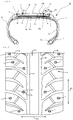
- the studdable tire 10 includes bead regions 11, bead cores 11C, a carcass layer 12, belt layers 13a, 13b, a tread 14, side treads 15, and studs 1.
- the carcass layer 12 is a framework member of the studdable tire 10 in a toroidal shape astride a pair of bead cores 11C disposed in the bead regions 11. Disposed on the radially outer side of the crown region of the carcass layer 12 are the inner belt layer 13a and the outer belt layer 13b.
- the belt layers 13a, 13b are each steel cord or cord of organic fiber strand crisscrossed at angles of 20 to 70 degrees with respect to the equatorial direction of the tire.
- the extension direction of the cords of the belt layer 13a disposed on the radially inner side and the extension direction of the cords of the belt layer 13b disposed on the radially outer side intersect with each other.
- the tread 14 is a rubber member (tread rubber) disposed on the radially outer side of the belt layers 13a, 13b.
- a plurality of main grooves 16 extending in the tire circumferential direction 10Y (see FIG. 5 ), and a plurality of land portions (blocks) 17A, 17B, 18 are defined by the main grooves 16.
- the land portion 17A is the middle land portion located in the tire center
- the land portions 17B are the outer land portions located on each outer side in the tire axial direction 10X of the middle land portion 17A (see FIG. 5 )
- the land portions 18 are the shoulder land portions located on each outer side in the tire axial direction 10X of the outer land portions 17B.
- sipes 19 Formed in the surfaces of the land portions 17A, 17B, 18 are a plurality of sipes 19.
- the side treads 15 are rubber members extending from the end of the tread 14 to the side region of the tire and covering the carcass layer 12.
- the belt protection layer 13c is Provided between the tread 14 and the outer belt layer 13b is a belt protection layer 13c which protects the outer belt layer 13b from getting pierced by the studs 1 due to the collapse of the rubber under them (radially inside rubber).
- the belt protection layer 13c has cords of organic fiber or the like.
- stud recesses 14b Formed in the surface of the tread 14 are stud recesses 14b and the studs 1 are fitted into the stud recesses 14b.
- the stud recesses 14b are provided in the shoulder land portions 18 and the outer land portions 17B, for instance.
- the stud recess (hole) 14b is formed into a cylindrical bottomed hole extending from the surface 14a of the tread 14 of the studdable tire 10 toward the center of the tire, for instance.
- the stud recess 14b has, for instance, an entry portion 14c, a bottom portion 14e, and an intermediate portion 14d which connects the entry portion 14c and the bottom portion 14e.
- the entry portion 14c, the bottom portion 14e, and the intermediate portion 14d are formed coaxial about the central axis of the stud recess 14b.
- the intermediate portion 14d is a cylindrical hole with a constant diameter.
- the entry portion 14c is a funnel-shaped hole surrounded by a conical surface (conical surface about the center line of the stud recess 14b) with the diameter increasing from the circular entry side of the intermediate portion 14d toward the surface 14a of the tread 14.
- the bottom portion 14e is a bottomed hole portion surrounded by a plane forming the bottom surface 14k by being increased from the circular bottom end of the intermediate portion 14d toward the circle center of the tire and then decreased to form the bottom surface 14k.
- the shape of the bottom surface 14k of the bottom portion 14e is preferably a shape corresponding to the shape of the flange section 4 of the stud 1.
- the stud 1 is driven into the stud recess 14b with the flange section 4 thereof first by a not-shown driving machine, so that the stud 1 is fitted in the stud recess 14b.
- the stud 1 is formed such that the height dimension thereof is greater than the depth dimension of the stud recess 14b.
- the studs 1 are fitted in the stud recesses 14b with the one-end side of the pin section 3 and body section 2 protruding from the surface 14a, for instance.
- the studs 1 according to the first embodiment are fitted in the stud recesses 14b such that the long axis 1L thereof extends in parallel with the tire axial direction 10X and the short axis 1S thereof in parallel with the tire circumferential direction 10Y.
- the studs 1 may also be fitted in the stud recesses 14b such that the long axis 1L thereof extends in parallel with the tire circumferential direction 10Y and the short axis 1S thereof in parallel with the tire axial direction X.
- the body section 2 is shaped with a pair of flat surface portions 21A, 22A opposite each other with the central axis 1C therebetween and a pair of curved surface portions 23A, 24A extending from the ends of the pair of flat surface portions 21A, 22A and outwardly bulging opposite each other with the central axis 1C therebetween.
- the body section 2 is shaped with the curved border surface portions 25A, 26A, 27A, 28A, which are the border portions between the flat surface portions 21A, 22A and the curved surface portions 23A, 24A outwardly bulging away from the central axis 1C.
- the curved border surface portions 25A, 26A, 27A, 28A are the border portions between the flat surface portions 21A, 22A and the curved surface portions 23A, 24A outwardly bulging away from the central axis 1C.
- the stud loss tends to occur with the progress of wear in the tread 14 of the tire. It is a phenomenon that often takes place at the sudden starting or acceleration of a vehicle and at the trailing end of the contact patch of the tire rolling on the road surface. Hence, it is more effectively resisted if the area of the trailing-end side outer periphery of the body section 2 is made larger that is in contact with the inside wall surface (rubber surface) of the stud recess 14b the longest before the stud loss.
- the length of the flat surface portions 21A, 22A (width length along the long axis 1L) will be too short. This will make the contact force between the flat surface portions 21A, 22A and the inside wall surface of the stud recess 14b smaller than the contact force between the curved surface portions 23A, 24A and the inside wall surface of the stud recess 14b. As a result, there will be increased chances of tumbling deformation of the studs 1 at braking and acceleration start, thus reducing the anti-stud-loss performance.
- the elliplicity of the sectional shape of the body section 2 is made smaller than 0, then the difference (clearance) between the major axis of the pin section 3 and the major axis of the upper part 2A of the body section 2 will be too small. This will reduce protection against damage to the pin section 3 by the thickness of the upper part 2A (approximately the robustness against external inputs other than road contact during ordinary travel of a vehicle) . And consequently there will be more troubles, such as damage to or loss of the pin section 3.
- the ellipticity defined by the major axis dimension and the minor axis dimension in the sectional shape orthogonal to the central axis 1C of the body section 2 is made larger than 0 and 0.2 or smaller.
- a studdable tire may also have the studs 1 fitted in the stud recesses formed in the surface of the tread thereof in such a manner that the longer direction of the body section 2 extends in the tire circumferential direction and the shorter direction thereof extends in the tire axial direction.
- peripheral edges (edges) of the end surface 3t of the pin section 3 have a pair of curved edge portions 33, 34 extending from the ends of the pair of straight edge portions 31, 32 and outwardly bulging opposite each other with the central axis 1C therebetween. Therefore, the length of the peripheral edges, or the length of the pin edges can be made longer to improve the pin edge performance for scratching the frozen road surface.
- the peripheral edges of the end surface 3t of the pin section 3 have a pair of straight edge portions 31, 32 and both end portions of the long axis 1L of the pin section 3 are not curved away from the central axis 1C. That is, the both end portions of the long axis 1L of the pin section 3 are not shaped with a bulge.
- the member thickness along the straight edge portions 31, 32 can be thickened, and the strength along the straight edge portions 31, 32 of the pin section 3 can be increased.
- the length of the pin edges in the dragging direction at braking can be made longer, which may lead to improved braking performance.
- the strength of the pin section 3 can be increased, which will provide a studdable tire 10 capable of reducing damage to the pin section 3, such as broken pin in the initial phase of vehicular travel due to insufficient strength in the fore-aft direction of the pin at braking or acceleration start.
- the peripheral edges of the end surface 3t of the pin section 3 has curved border edge portions 35, 36, 37, 38, which are border portions between the straight edge portions 31, 32 and the curved edge portions 33, 34 outwardly bulging away from the central axis 1C.
- the border portions are shaped angular, there will be less stress concentration at the border portions, which can reduce wear and damage to the pin section 3.
- the sectional shape is not so different from a circle, with the result that no improvement can be expected in the braking and acceleration performance compared with the pin section having a circular cross section.
- the minor axis of the pin section 3 becomes too short in comparison with the major axis thereof, which can cause broken pins in the initial phase of vehicular travel due to insufficient fore-aft strength of the pin section 3 at braking or acceleration start.
- the ellipticity defined by the maj or axis dimension a and the minor axis dimension b in shape of the end surface 3t of the pin section 3 and the sectional shape orthogonal to the central axis 1C of the pin section 3 is made 0.3 or larger and 0.6 or smaller.
- the length of the pin edges can be made longer, which may result in improved braking and acceleration performance.
- the strength in the fore-aft direction of the pin at braking or acceleration start can be increased, which will provide a studdable tire 10 capable of reducing damage to the pin section 3, such as broken pin in the initial phase of vehicular travel.
- a studdable tire may also have the studs 1 fitted in the stud recesses formed in the surface of the tread thereof in such a manner that the longer direction of the pin section 3 extends in the tire circumferential direction and the shorter direction thereof extends in the tire axial direction.
- the flange section 2 the shape of the peripheral profile lines of the cross section orthogonal to the central axis 1C is formed with a pair of straight portions 41, 42 opposite each other with the central axis 1C therebetween and a pair of curved portions 43, 44 extending from the ends of the pair of straight portions 41, 42 and outwardly bulging opposite each other with the central axis 1C therebetween.
- the flange section 4 is formed with curved border portions 45, 46, 47, 48, which are border portions between the straight portions 41, 42 and the curved portions 43, 44 outwardly bulging away from the central axis 1C.
- the peripheral surface 4F of the flange section 4 which prevents cracking from occurring in the inside wall surface of the stud recess 14b resulting if any edged corner comes in contact with the inside wall surface of the stud recess 14b.
- the tumbling deformation of the studs 1 at braking or acceleration start can be prevented, which will provide a studdable tire 10 with improved anti-stud-loss performance.
- the width length of the straight portions 41, 42 along the long axis 1L will be too short. This will make the contact force between the straight portions 41, 42 and the inside wall surface of the stud recess 14b relatively small in comparison with the contact force between the curved portions 43, 44 and the inside wall surface of the stud recess 14b. As a result, there will be increased chances of tumbling deformation of the studs 1 at braking or acceleration start, thus reducing the anti-stud-loss performance.
- the elliplicity of the flange section 4 is made smaller than 0.1, then the difference (clearance) between the minor axis of the pin section 3 and the minor axis of the flange section 4 will be too small. As a result, there will be increased chances of tumbling deformation of the studs 1 at braking or acceleration start, thus reducing the anti-stud-loss performance.
- the ellipticity defined by the maj or axis dimension a and the minor axis dimension b in the sectional shape orthogonal to the central axis 1C of the flange section 4 is made 0.1 or larger and 0.25 or smaller.
- a studdable tire may also have the studs 1 fitted in the stud recesses formed in the surface of the tread thereof in such a manner that the longer direction of the flange section 4 extends in the tire circumferential direction and the shorter direction thereof extends in the tire axial direction.
- the flange section 4 is formed such that the diameter (axis length) of the peripheral surface 4F increases from one end to the other end thereof along the central axis 1C. And the maximum peripheral diameter position 4M of the peripheral surface 4F of the flange section 4 is located closer to the other end surface 4E of the flange section 4 than to the 1/2 position of the thickness dimension of the flange section along the central axis 1C. Hence, when the stud 1 is driven into the stud recess 14b, the maximum peripheral diameter position 4M of the flange section 4 is located at a position closer to the belt layers 13a, 13b of the tire.
- the maximum peripheral diameter position 4M of the flange section 4 be located at a position as close to the other end surface 4E of the flange section 4 as practicable.
- the flange section 4 is formed such that the maximum peripheral diameter position 4M is formed into a curved surface, and at the same time the border portion between the maximum peripheral diameter position 4M of the peripheral surface 4F and the other end surface 4E of the flange section 4 is formed into a curved surface 4G outwardly bulging away from the central axis 1C.
- the peripheral surface 4F and the border between the other end surface 4E and the peripheral surface 4F which prevents cracking from occurring in the inside wall surface of the stud recess 14b resulting if any edged corner comes in contact with the inside wall surface of the stud recess 14b.
- the tumbling deformation of the studs 1 at braking or acceleration start can be prevented, thus improving the anti-stud-loss performance.
- the longer direction of the pin section 3, the longer direction of the flange section 4, and the longer direction of the body section 2 are aligned with each other, and the shorter direction of the pin section 3, the shorter direction of the flange section 4, and the shorter direction of the body section 2 are aligned with each other.
- the body section 2 and the flange section 4 are formed such that the pin section 3 displays adequate edge effects in the necessary directions.
- the stud according to the first embodiment is so constituted that the straight edge portions provide edge effects and the curved edge portions provide pin durability and satisfy the weight limit.
- a studdable tire 10 has the studs 1 fitted in the stud recesses 14b provided therein such that the longer direction of the pin section 3, the flange section 4, and the body section 2 extends in the tire axial direction 10X and shorter direction of the pin section 3, the flange section 4, and the body section 2 extends in the tire circumferential direction 10Y.
- the studdable tire 10 can feature improved anti-stud-loss performance.
- the anti-stud-loss performance can be improved by making the difference between the diameter of the flange section 4 and the diameter of the upper part 2A small. Therefore, the shape of the stud is satisfactory if at least the longer direction of the pin section 3 and the longer direction of the flange section 4 are aligned with each other and the shorter direction of the pin section 3 and the shorter direction of the flange section 4 are aligned with each other.
- the arrangement may also be such that the studdable tire 10 has the studs 1 fitted in the stud recesses 14b provided therein with the longer direction of the pin section 3, the flange section 4, and the body section 2 extending in the tire circumferential direction 10Y and the shorter direction of the pin section 3, the flange section 4, and the body section 2 extending in the tire axial direction 10X.
- the stud 1 has the upper part 2A and the flange part 4 whose diameter (length) along the short axis 1S thereof is the same or nearly the same, so that the difference between the diameter of the flange part 4 and the diameter of the upper part 2A along the short axis 1S thereof is as small as practicable.
- the studdable tire 10 has the studs 1 fitted in the stud recesses 14b provided therein with the short axis 1S thereof extending in the tire circumferential direction 10Y and the long axis 1L thereof extending in the tire axial direction 10X.
- the studdable tire 10 features improved anti-stud-loss performance.
- the stud 1 may have a body section 2X which has peripheral profile lines of the cross section orthogonal to the central axis 1C such that there is a difference in the length between the pair of straight edge portions constituting the peripheral edges (edges) of the end surface 2t, or in the width length (length along the long axis 1L) of the pair of flat surface portions constituting the peripheral surface.
- the stud 1 according to the third embodiment is a stud 1 having a body section 2X whose peripheral surfaces are comprised of a pair of flat surface portions 21Aa, 22Aa, having different width lengths, opposite each other with the central axis 1C therebetween, a pair of curved surface portions 23Aa, 24Aa extending from the ends of the pair of flat surface portions 21Aa, 22Aa and outwardly bulging opposite each other with the central axis 1C therebetween, and curved border surface portions 25Aa, 26Aa, 27Aa, 28Aa, which are border portions between the flat surface portions 21Aa, 22Aa and the curved surface portions 23Aa, 24Aa outwardly bulging away from the central axis 1C.
- the body section 2X has a pair of straight edge portions 21a, 22a, having the peripheral profile lines of the cross section orthogonal to the central axis 1C and the peripheral edges (edges) of the end surface 2t of different lengths, opposite each other with the central axis 1C therebetween, a pair of curved edge portions 23a, 24a extending from the ends of the pair of straight edge portions 21a, 22a and outwardly bulging opposite each other with the central axis 1C therebetween, and curved border edge portions 25a, 26a, 27a, 28a, which are border portions between the straight edge portions 21a, 22a and the curved edge portions 23a, 24a outwardly bulging away from the central axis 1C.
- the body section 2X is formed such that the peripheral profile lines of the cross section orthogonal to the central axis 1C and the peripheral edges (edges) of the end surface 2t are symmetrical in shape with respect to the short axis 1S.
- the stud loss tends to occur with the progress of wear in the tread of the tire. It is a phenomenon that often takes place at the sudden starting or sudden acceleration of a vehicle and at the trailing end of the contact patch of the tire rolling on the road surface. Hence, it is more effectively resisted if the area of the trailing-end side outer periphery of the body section (upper part 2A) is made larger that comes in contact with the inside wall surface (rubber surface) of the stud recess the longest before the stud loss.
- the stud 1 according to the third embodiment is fitted in the stud recess 14b in such a manner that the shorter straight edge portion 22a, which is the flat surface portion 22A with a shorter width length, is located on the leading-end side, and the longer straight edge portion 21a, which is the flat surface portion 21A with a longer width length, is located on the trailing-end side.
- the tumbling deformation of the studs 1 at braking or acceleration start can be prevented, which will provide a studdable tire 10 with improved anti-stud-loss performance.
- location of the shorter straight edge portion 22a of the upper part 2A on the leading-end side of the block and location of the longer straight edge portion 21a on the trailing-end side of the block are in consideration of a certain limiting condition on weight per stud. That is, when the studs 1 are fitted in the tire with the shorter straight edge portion 22a of the upper part 2A located on the leading-end side of the block and the longer straight edge portion 21a on the trailing-end side of the block, an improvement in the edge effect, durability, and anti-stud-loss performance can be expected under the limiting condition of the same weight.
- the stud 1 may have a pin section 3X which has peripheral profile lines of the cross section orthogonal to the central axis 1C and the pair of curved edge portions constituting the peripheral edges (edges) of the end surface 3t having different curvatures from each other.
- the stud 1 according to the fourth embodiment is a stud 1 having a pin section 3X whose peripheral surfaces are comprised of a pair of flat surface portions 31Aa, 32Aa opposite each other with the central axis 1C therebetween, a pair of curved surface portions 33Aa, 34Aa, having different curvatures from each other, extending from the ends of the pair of flat surface portions 31Aa, 32Aa and outwardly bulging opposite each other with the central axis 1C therebetween, and curved border surface portions 35Aa, 36Aa, 37Aa, 38Aa, which are border portions between the flat surface portions 31Aa, 32Aa and the curved surface portions 33Aa, 34Aa outwardly bulging away from the central axis 1C.
- the pin section 3X has a pair of straight edge portions 31a, 32a, having the peripheral profile lines of the cross section orthogonal to the central axis 1C and the peripheral edges (edges) of the end surface 3t opposite each other with the central axis 1C therebetween, a pair of curved edge portions 33a, 34a extending from the ends of the pair of straight edge portions 31a, 32a and outwardly bulging opposite each other with the central axis 1C therebetween, and curved border edge portions 35a, 36a, 37a, 38a, which are border portions between the straight edge portions 31a, 32a and the curved edge portions 33a, 34a outwardly bulging away from the central axis 1C.
- the studs 1 are fitted in the stud recesses 14b in such a manner that the curved edge portion 34a with a smaller curvature radius of the pin section 3X is located on the leading-end side and the curved edge portion 33a with a larger curvature radius of the pin section 3X is located on the trailing-end side.
- the scratch effect of the pin section 3X at the time of tire engagement with the ground is reduced with the curved edge portion 34a with a smaller curvature radius located on the leading-end side of tire rolling. This will improve the anti-stud-loss performance.
- location of the curved edge portion 34a with a smaller curvature radius of the pin section 3X on the leading-end side of the block and the curved edge portion 33a with a larger curvature radius of the pin section 3X on the trailing-end side of the block is in consideration of the certain limiting condition on weight per stud. That is, when the studs 1 are fitted in the tire with the curved edge portion 34a with a smaller curvature radius located on the leading-end side of the block and the curved edge portion 33a with a larger curvature radius of the pin section 3X on the trailing-end side of the block, an improvement in the edge effect, durability, and anti-stud-loss performance can be expected under the limiting condition of the same weight.
- the stud 1 may have a flange section 4X which has peripheral profile lines of the cross section orthogonal to the central axis 1C and a pair of straight portions constituting the peripheral edges (edges) of the other end surface 4E having different lengths from each other.
- the stud 1 according to the fifth embodiment is a stud 1 having a flange section 4X whose peripheral surfaces are comprised of a pair of straight surface portions 41Aa, 42Aa, having different width lengths from each other, opposite each other with the central axis 1C therebetween, a pair of curved surface portions 43Aa, 44Aa extending from the ends of the pair of straight surface portions 41Aa, 42Aa and outwardly bulging opposite each other with the central axis 1C therebetween, and curved border surface portions 45Aa, 46Aa, 47Aa, 48Aa, which are border portions between the straight surface portions 41Aa, 42Aa and the curved surface portions 43Aa, 44Aa outwardly bulging away from the central axis 1C.
- the flange section 4X has a pair of straight portions 21a, 22a, having the peripheral profile lines of the cross section orthogonal to the central axis 1C of different lengths, opposite each other with the central axis 1C therebetween, a pair of curved portions 43a, 44a extending from the ends of the pair of straight portions 41a, 42a and outwardly bulging opposite each other with the central axis 1C therebetween, and curved border portions 45a, 46a, 47a, 48a, which are border portions between the straight portions 41a, 42a and the curved portions 43a, 44a outwardly bulging away from the central axis 1C.
- the stud loss tends to occur with the progress of wear in the tread of the tire. It is a phenomenon that often takes place at the sudden starting or sudden acceleration of a vehicle. Hence, it is more effectively resisted if the contact area of the trailing-end side of the flange section is made larger that is in contact the longest before the stud loss.
- the studs 1 according to the fifth embodiment are fitted in the stud recesses 14b in such a manner that the shorter straight portion 42a, which is the straight surface portion 42Aa with a shorter width length, is located on the leading-end side, and the longer straight portion 41a, which is the straight surface portion 41Aa with a longer width length, is located on the trailing-end side.
- the tumbling deformation of the studs 1 at braking or acceleration start can be prevented, which will provide a studdable tire 10 with improved anti-stud-loss performance.
- location of the shorter straight portion 42a of the flange section 4 on the leading-end side of the block and the longer straight portion 41a on the trailing-end side of the block is in consideration of the certain limiting condition on weight per stud. That is, when the studs 1 are fitted in the tire with the shorter straight portion 42a of the flange section 4 located on the leading-end side of the block and the longer straight portion 41a on the trailing-end side of the block, an improvement in the edge effect, durability, and anti-stud-loss performance can be expected under the limiting condition of the same weight.
- the stud 1 is so configured as to have a body section 2X according to the third embodiment, a pin section 3X according to the fourth embodiment, and a flange section 4X according to the fifth embodiment.
- the studs 1 are fitted in the stud recesses 14b with the shorter flat surface portion 22a of the body 2X, the curved surface portion 34a with a smaller curvature radius of the pin section 3X, and the shorter straight surface portion 42a of the flange section 4X located on the leading-end side.
- This will provide a studdable tire 10 featuring the effects as described in the third to fifth embodiments.
- location of the shorter flat surface portion 22a of the body 2X, the curved surface portion 34a with a smaller curvature radius of the pin section 3X, and the shorter straight surface portion 42a of the flange section 4X on the leading-end side of the block is in consideration of the certain limiting condition on weight per stud. That is, when the studs 1 are fitted in the tire with the shorter flat surface portion 22a of the body 2X, the curved surface portion 34a with a smaller curvature radius of the pin section 3X, and the shorter straight surface portion 42a of the flange section 4X located on the leading-end side of the block, an improvement in the edge effect, durability, and anti-stud-loss performance can be expected under the limiting condition of the same weight.
- the stud 1 has the central axis 4Z of the flange section 4X as described in the sixth embodiment, the central axis 3Z of the pin section 3X, and the central axis 2Z of the body section 2X staggered from each other.
- the stud 1 is so configured that the central axis 3Z of the pin section 3X and the central axis 2Z of the body section 2X are located on the side closer to the longer straight surface portion 41a of the flange section 4X of the central axis 4Z of the flange section 4X.
- the studs 1 are fitted in the stud recesses 14b in such a manner that the shorter flat surface 22a of the body section 2X, the curved surface portion 34a with a smaller curvature radius of the pin section 3X, and the shorter straight surface 0portion 42a of the flange section 4X are located on the leading-end side.
- the studdqble tire 10 has the studs 1 whose central axis 3Z of the pin section 3X and central axis 2Z of the body section 2X are offset to the trailing-end side from the central axis 4Z of the flange section 4X
- the trailing-end diameter (axis length) are smaller than the leading-end diameter differences therebetween. This will work to restrict the rotational deformation of the stud 1 on the trailing-end side where the stud 1 is in contact the longest before it falls out, thus improving the anti-stud-loss performance.
- the stud is preferably structured such that, as in the above-described sixth embodiment (see FIG. 9 ) and the seventh embodiment (see FIG. 10 ), the peripheral profile lines and peripheral edges of the body section have a pair of flat surface portions 21a, 22a of different lengths, the peripheral profile lines and peripheral edges of the pin section have a pair of curved surface portions 33a, 34a of different curvature radii, the peripheral profile lines of the flange section have a pair of straight surface portions 41a, 42a of different lengths, and at the same time the shorter flat surface portion 22a, the curved surface portion 34a of a smaller curvature radius, and the shorter straight surface portion 42a are all located on the same side.
- a studdable tire is preferably structured using the studs fitted thereon in such a manner that the shorter flat surface portion 22a of the body section 2X, the curved surface portion 34a of a smaller curvature radius of the pin section 3X, and the shorter straight surface portion 42a of the flange section 4X are located on the leading-end side or the trailing-end side of tire blocks.
- the shorter flat surface portion 22a, the curved surface portion 34a of a smaller curvature radius, and the shorter straight surface portion 42a being all located on the same side means that the short axis 1S passes through the middle point of the shorter flat surface portion 22a, the middle point of the curved surface portion 34a of a smaller curvature radius, and the middle point of the shorter straight surface portion 42a and the shorter flat surface portion 22a, the curved surface portion 34a of a smaller curvature radius, and the shorter straight surface portion 42a are located on one side of the long axis 1L.
- the stud may be so structured that the short axis 1S passes through the middle point of the shorter flat surface portion 22a, the middle point of the curved surface portion 34a of a smaller curvature radius, and the middle point of the shorter straight surface portion 42a, and the shorter flat surface portion 22a of the body section and the curved surface portion 34a of a smaller curvature radius of the pin section are located on one side of the long axis 1L and the shorter straight surface portion 42a of the flange section is located on the other side of the long axis 1L.
- the stud may be so structured that the shorter straight surface portion 42a of the flange section is located on the opposite side of the shorter straight surface portion 22a of the body section 2X and the curved surface portion 34a of a smaller curvature radius of the pin section 3X, with the long axis 1L as the boundary.
- the stud 1 may have a pin section 3Y, instead of the pin section as described in the foregoing embodiments, such that the pin section 3Y has a height dimension at one end in the pin diameter direction orthogonal to the central axis 1C (length dimension along the central axis 1C) different from the height dimension at the other end in the pin diameter direction.
- one end and the other end in the pin diameter direction are at the respective end positions on the shortest pin diameter (axis length) line passing through the central axis, that is, the above-described short axis 1S (see FIG. 1 ).
- the pin section 3Y may be so formed that at one of the ends in the diameter direction of the pin section 3Y intersecting with the short axis 1S, the border portion 3s between the end surface 3t of the pin section 3Y and the periphery surface 3r of the pin section 3Y is constituted by a curved border surface portion outwardly bulging away from the central axis 1C.
- one curved edge portion 33 which is one of the pair of the curved edge portions 33, 34 constituting the peripheral edges (edges) of the end surface 3t of the pin section 3 as described in the first embodiment, may be constituted by the above-mentioned curved border surface portion.
- r1 is the curvature radius of the border portion 3s between the end surface 3t of the pin section 3Y and the peripheral surface 3r at one of the pair of the curved edge portions 33, 34
- r2 is the curvature radius of the border portion 3e between the end surface 3t of the pin section 3Y and the peripheral surface 3r of the pin section 3Y at the other of the pair of the curved edge portions 33, 34.
- the curvature radius in the vertical cross section of the border portion 3s between the leading-end end surface (end surface 3t) of the pin section 3Y and the peripheral surface 3r is larger (rounded pin edge). This can reduce the scratch effect of the leading-end side of the pin section 3Y which first comes in contact with the ground at acceleration start, thus improving the anti-stud-loss performance.
- the curvature radius in the vertical cross section of the border portion 3e between the trailing-end end surface 3t of the pin section 3Y and the peripheral surface 3r is smaller (sharp pin edge). This can increase the scratch effect of the trailing-end side of the pin section 3Y which becomes dragging front at the time of braking, thus improving the braking performance.
- the border portion 3s may, for instance, be an oblique plane (bevel) instead of a curved surface.
- the stud is allowable if it has a pin section having a height dimension at one end in the pin diameter direction different from the height dimension at the other end in the pin diameter direction. This will work to combine the anti-stud-loss performance and the braking performance, which are otherwise mutually warring performances.
- the stud 1 may have a body section 2Y having a lower part 2B1 with a cone-shaped outer periphery formed such that the diameter (axis length) in the cross section orthogonal to the central axis 1C gradually increases from the middle part 2C side toward the flange section 4 and the lower part 2B1 connects to the peripheral surface of the flange section 4.
- the angle ⁇ of the oblique plane (bevel), constituting the peripheral surface of the lower part 2B1 from the cross section orthogonal to the central axis 1C of the lower part 2B1 is preferably 20 deg ⁇ ⁇ ⁇ 60 deg.
- peripheral surfaces are surfaces in parallel with the central axis 1C as with the lower part 2B already described, the peripheral surfaces do not easily come in contact with the inner peripheral surface of the stud recess 14b, presenting less resistance to the tumbling deformation of the stud 1.
- the peripheral surfaces are formed in sloping surfaces gradually larger from the middle part 2C to the flange section 4 as those of the lower part 2B1 of the ninth embodiment, then there will be easier contact between the sloping surfaces and the rubber of the inner peripheral surface of the stud recess 14b, presenting greater friction therebetween. This will increase the resistance to the tumbling deformation of the stud 1, thus improving the anti-stud-loss performance.
- the stud may have the end surface of the pin section as described in the foregoing embodiments having grooves as already explained with reference to FIG. 13 .
- the grooves may be cross shaped as shown in FIG. 13 or in a straight line.
- These grooves are desirable because they can help the removal therethrough of ice powder having been scraped and shaved off by the pin section 3, thus preventing the accumulation of ice powder on one end surface of the pin section 3.
- the stud according to one aspect of the present invention is comprised of a columnar body section, a pin section disposed at one end along the central axis of the body section, and a flange section disposed at the other end along the central axis of the body section.
- the pin section has a pair of straight edge portions whose peripheral edges at one end surface along the central axis, or the peripheral profile lines of the cross section orthogonal to the central axis, opposite each other with the central axis therebetween, a pair of curved edge portions extending from the ends of the pair of straight edge portions and outwardly bulging away from each other with the central axis therebetween, and curved border edge portions between the straight edge portions and the curved edge portions outwardly bulging away from the central axis.
- the stud thus provided displays great edge effect and excellent braking and acceleration performance.
- the stud features improved anti-stud-loss performance and high durability of the pin section which has greater strength capable of reducing damage thereto.
- other embodiments feature a difference in curvature between one curved edge portion and the other curved edge portion of the pair of curved edge portion.
- the stud thus provided displays great edge effect and excellent braking and acceleration performance.
- the stud features improved anti-stud-loss performance and high durability of the pin section having greater strength capable of reducing damage thereto.
- the studdable tire according to one aspect of the present invention has the studs fitted in the stud recesses in such a manner that the longer direction of the pin section intersecting with the pair of straight edge portions orthogonal to the central axis extends in the tire axial direction and the shorter direction of the pin section orthogonal to the longer direction extends in the tire circumferential direction.
- the stud thus provided displays great edge effect and excellent braking and acceleration performance.
- the stud features improved anti-stud-loss performance and high durability of the pin section having greater strength capable of reducing damage thereto.
- the studdable tire according to another aspect of the present invention has the studs fitted in the stud recesses in such a manner that the longer direction of the pin section intersecting with the pair of straight edge portions orthogonal to the central axis extends in the tire circumferential direction and the shorter direction of the pin section orthogonal to the longer direction extends in the tire axial direction.
- the stud displayed great edge effect and excellent braking and acceleration performance.
- the stud features improved anti-stud-loss performance and high durability of the pin section with greater strength capable of reducing damage thereto.
Landscapes
- Engineering & Computer Science (AREA)
- Mechanical Engineering (AREA)
- Tires In General (AREA)
Abstract

Description
- The present invention relates to a stud for a studdable tire (hereinafter referred to simply as "stud") and a studdable tire having the studs fitted thereon.
- Conventionally, as shown in
FIG. 13 , astud 100 is formed into a columnar body along acentral axis 100C, with abody section 120, apin section 130 disposed on one end of the body section along thecentral axis 100C, and aflange section 140 disposed on the other end of the body section along thecentral axis 100C. And thestud 100 is embedded in the tread surface of a tire with theflange section 140 first fitted into a stud recess (hole) formed in the tread surface in such a manner that thepin section 130 protrudes from the tread surface 140 (seeFIG. 14 ). And thestud 100 known in the art has thebody section 120, thepin section 130, and theflange section 140, and is formed such that the sectional shape orthogonal to thecentral axis 100C is circular. - Here, the
central axis 100C refers to the axis of rotation center of the pin section, the body section, and the flange section of a stud embedded in the direction of tire radius (depth direction), that is, the axis of the median point in the cross section orthogonal to the tire radial direction. - That is, the
stud 100 is formed in a cylindrical shape with thebody section 120 and thepin section 130 extending in the direction along thecentral axis 100C. And formed on one end (end surface) of thepin section 130 aregrooves 132 in a cross shape in planar view extending in directions orthogonal to thecentral axis 100C. -
FIG. 14 shows how astud 100 fitted in the stud recess formed in the tread surface of a studdable tire falls off from a worn tread surface at a sudden starting or acceleration of the vehicle. InFIG. 14 , W stands for the direction of the rolling motion of thestuddable tire 150, F the leading-end side where thestuddable tire 150 in the rolling motion first touches the ground, and R the trailing-end side where thestuddable tire 150 in the rolling motion touches the ground later. - The
studdable tire 150 is required of having the durability performance of thepin section 130, the edge performance of thepin section 130 to scratch the ice on the road surface, and the anti-stud-loss performance to resist the falling out of thestuds 100. - Also known is a
stud 100 formed in an elliptical cylinder shape (see Patent Document 1) . The stud consists of a body section, a pin section disposed on one end of the body section along the central axis of the body section, and a flange section disposed on the other end of the body section along the central axis. And the stud is embedded in the tread surface of a tire with the flange section first fitted into a stud recess formed in the tread surface in such a manner that the pin section protrudes from the tread surface. - Patent Document 1: Japanese Patent No.
4088055 - However, the stud disclosed in
Patent Document 1 has an elliptically shaped peripheral edge at the end of the pin section. As a result, the stud is prone to damage to the pin section at the time of braking or acceleration due to the insufficient strength in the end portions of the major axis of the elliptical shape. Furthermore, the use of simply circular or elliptical shape has not ensured sufficient edge effect or anti-stud-loss performance. - The present invention aims to provide a stud featuring excellent braking and acceleration performance due to high edge effect, improved anti-stud-loss performance, and high durability of the pin section having strength to resist damage thereto, and a studdable tire fitted with such studs.
- According to one aspect of the present invention, there is provided a stud including a body section in a columnar shape, a pin section disposed on one end of the body section along the central axis thereof, and a flange section disposed on the other end of the body section along the central axis thereof. And the pin section of the stud has a pair of straight edge portions defined by the peripheral edges at one end thereof along the central axis, or the peripheral profile lines in the cross section orthogonal to the central axis, opposite each other with the central axis therebetween, a pair of curved edge portions extending from the ends of the pair of straight edge portions and outwardly bulging away from each other with the central axis therebetween, and curved border edge portions between the straight edge portions and the curved edge portions outwardly bulging away from the central axis.
-
-
FIG. 1A is a plan view of a stud (first embodiment), andFIG. 1B a front view of a stud (first embodiment). -
FIG. 2 is a perspective view of a stud (first embodiment). -
FIG. 3 shows how to fit a stud in a stud recess (first embodiment). -
FIG. 4 is a cross section of a studdable tire (first embodiment). -
FIG. 5 is an illustration showing a tread surface of a studdable tire (first embodiment). -
FIG. 6A is a plan view of a stud (third embodiment), andFIG. 6B a front view of a stud (third embodiment). -
FIG. 7A is a plan view of a stud (fourth embodiment), andFIG. 7B a front view of a stud (fourth embodiment). -
FIG. 8A is a plan view of a stud (fifth embodiment), andFIG. 8B a front view of a stud (fifth embodiment). -
FIG. 9A is a plan view of a stud (sixth embodiment), andFIG. 9B a front view of a stud (sixth embodiment). -
FIG. 10A is a plan view of a stud (seventh embodiment), andFIG. 10B a front view of a stud (seventh embodiment). -
FIG. 11 is a front view of a stud (eighth embodiment). -
FIG. 12 is a front view of a stud (ninth embodiment). -
FIG. 13A is a plan view of a stud (conventional example), andFIG. 13B a front view of a stud (conventional example). -
FIG. 14 is an illustration showing how a stud falls out from a worn block of a tire. - With reference to
FIGS. 1 to 5 , a description is given of a stud according to the first embodiment of the invention to be embedded in the tread surface of a studdable tire (studded tire). - As shown in
FIG. 1 andFIG. 2 , astud 1, which is comprised of abody section 2, apin section 3 disposed on one end of thebody section 2 along the central axis of thebody section 2, and aflange section 4 disposed on the other end along the central axis of thebody section 2, is a columnar member extending along the central axis of thebody section 2. - The
stud 1 according to the first embodiment is formed with the central axis of thebody section 2 in line (continuous straight line) with the central axis of thepin section 3 and the central axis of theflange section 4. And the continuous straight line constitutes thecentral axis 1C of the stud 1 (hereinafter referred to simply as "central axis 1C"). - It is to be noted that the
central axis 1C refers to the axis of rotation center of the pin section, the body section, and the flange section of a stud embedded in the direction of tire radius (depth direction), that is, the axis of the median point in the cross section orthogonal to the tire radial direction. In other words, thecentral axis 1C is the central axis extending in the direction of extension of thestud 1 positioned at the median point in the cross section orthogonal to the direction of extension of thestud 1 embedded in a tire. - As shown in
FIG. 3 andFIG. 4 , thestud 1 is embedded in thesurface 14a side of thetread 14 of a tire with theflange section 4 first fitted into astud recess 14b (seeFIG. 3 ) formed in thetread surface 14a. Thus, a studdable tire (studded tire) 10 (seeFIG. 4 ) is formed with thepin section 3, which is one end of thestud 1, protruding from thesurface 14a side of thetread 14. - As shown in
FIG. 1 andFIG. 2 , thebody section 2 has anupper part 2A located on one end along thecentral axis 1C, alower part 2B located on the other end along thecentral axis 1C, and amiddle part 2C connecting theupper part 2A and thelower part 2B. - The
upper part 2A is formed in a columnar body in the same shape in cross section orthogonal to thecentral axis 1C for the whole length along thecentral axis 1C. - The
lower part 2B is formed in a columnar body in the same shape in cross section orthogonal to thecentral axis 1C for the whole length along thecentral axis 1C. - The sectional diameter (axis length) of the
upper part 2A and the sectional diameter of thelower part 2B are in a relationship of "sectional diameter of theupper part 2A > sectional diameter of thelower part 2B". - The
middle part 2C is formed in a cone-shaped columnar body whose sectional diameter orthogonal to thecentral axis 1C reduces gradually from theupper part 2A side to thelower part 2B side. - The outer periphery of the
body section 2 consists of a pair offlat surface portions central axis 1C therebetween, a pair ofcurved surface portions flat surface portions central axis 1C therebetween, and curvedborder surface portions flat surface portions curved surface portions central axis 1C. - That is, the outer periphery of the
body section 2 is formed with one end of thecurved surface portion 23A, which is one of the pair ofcurved surface portions flat surface portion 21A, which is one of the pair offlat surface portions border surface portion 25A, the other end of onecurved surface portion 23A connected with one end of the otherflat surface portion 22A via the curvedborder surface portion 26A, one end of the othercurved surface portion 24A connected with the other end of oneflat surface portion 21A via the curvedborder surface portion 27A, and the other end of the othercurved surface portion 24A connected with the other end of the otherflat surface portion 22A via the curvedborder surface portion 28A. The curved border surface portions are each connected with a flat surface portion at one end and with a curved surface portion at the other end. - It is to be noted that the
curved surface portions - Also, the outer periphery of the
body section 2 refers to the peripheral side surfaces extending in the same direction as thecentral axis 1C. In other words, the outer periphery of thebody section 2 is the surface extending along thecentral axis 1C and surrounding the central axis. - Also, as shown in
FIG. 1A , thebody section 2 is the most preferably of a constitution having a pair ofstraight edge portions central axis 1C and the peripheral edges (edges) at one end along thecentral axis 1C (hereinafter referred to as "end surface 2t") opposite each other with thecentral axis 1C therebetween, a pair ofcurved edge portions straight edge portions central axis 1C therebetween, and curvedborder edge portions straight edge portions curved edge portions central axis 1C. The curved border edge portions are each connected to a straight edge portion at one end and to a curved edge portion at the other end. - It is to be noted that the
curved edge portions - The
end surface 2t of thebody section 2 is formed into a flat surface orthogonal to thecentral axis 1C or a curved surface bulging toward one end thereof along thecentral axis 1C or a curved surface depressed toward the other end thereof along thecentral axis 1C, for instance. - The pair of
flat surface portions upper part 2A are formed by parallel flat surfaces opposite each other with thecentral axis 1C therebetween. The pair ofcurved surface portions upper part 2A are formed by curved surfaces having the same curvature and the same distance to thecentral axis 1C. The length of the pair offlat surface portions upper part 2A in the plane orthogonal to thecentral axis 1C (that is, the length of the straight line intersecting the plane orthogonal to thecentral axis 1C on the pair offlat surface portions upper part 2A (hereinafter referred to as "width length")) is the same as the length of each of thestraight edge portions curved surface portions upper part 2A in the plane orthogonal to thecentral axis 1C (that is, the length of the curved line intersecting the plane orthogonal to thecentral axis 1C on the pair ofcurved surface portions upper part 2A (hereinafter referred to as "width length")) is the same as the length of each of thecurved edge portions end surface 2t of theupper part 2A is congruent to the shape of the peripheral profile lines of the cross section of theupper part 2A orthogonal to thecentral axis 1C. - The pair of
flat surface portions lower part 2B are formed by parallel flat surfaces opposite each other with thecentral axis 1C therebetween. The pair ofcurved surface portions lower part 2B are formed by curved surfaces having the same curvature and the same distance to thecentral axis 1C. The width length of the pair offlat surface portions lower part 2B is the same as the length of each of thestraight edge portions curved surface portions lower part 2B is the same as the length of each of thecurved edge portions - The pair of
flat surface portions middle part 2C are formed by flat surfaces opposite each other with thecentral axis 1C therebetween with reducing distance between the opposite surfaces from theupper part 2A side to thelower part 2B side. The pair ofcurved surface portions middle part 2C are formed by curved surfaces having the same curvature and the same distance to thecentral axis 1C. The width length of the pair offlat surface portions middle part 2C is the same as the length of each of thestraight edge portions curved surface portions middle part 2C is the same as the length of each of thecurved edge portions - The shape of the peripheral edges of the
end surface 2t of theupper part 2A (endsurface 2t of the body section 2), the shape of the peripheral profile lines of the cross section orthogonal to thecentral axis 1C of theupper part 2A, the shape of the peripheral profile lines of the cross section orthogonal to thecentral axis 1C of thelower part 2A, and the shape of the peripheral profile lines of the cross section orthogonal to thecentral axis 1C of themiddle part 2C are formed into a 180-degree rotational symmetry with thecentral axis 1C at the center of rotation. - The 180-degree rotational symmetry is a shape formed by the four corners of a square rounded by the curved
border edge portions - That is, the shape of the peripheral edges of the
end surface 2t of thebody section 2 and the shape of the peripheral profile lines of thebody section 2 are in a 180-degree rotational symmetry constituted by a pair ofstraight edge portions central axis 1C therebetween, a pair ofcurved edge portions straight edge portions central axis 1C therebetween, and the curvedborder edge portions straight edge portions curved edge portions central axis 1C. - In other words, the sectional shape of the
body section 2 orthogonal to thecentral axis 1C and the shape of theend surface 2t have along axis 1L and ashort axis 1S passing through thecentral axis 1C and orthogonal to each other in the cross section orthogonal to thecentral axis 1C. And they are symmetrical with respect to thelong axis 1L or theshort axis 1S as the axis of symmetry. It is to be noted that the direction along thelong axis 1L is hereinafter referred to as the longer direction of thestud 1, and the direction along theshort axis 1S as the shorter direction of thestud 1. - And the maximum distance between the
curved edge portions long axis 1L is defined as the major axis dimension, and the distance between thestraight edge portions short axis 1S as the minor axis dimension. In this case, the ellipticity of the sectional shape of thebody section 2 defined by the major axis dimension and the minor axis dimension is greater than 0 and equal to or less than 0.2.
- a: major axis dimension
- b: minor axis dimension
- That is, the relationship between the major axis dimension a, which is the maximum distance between the pair of
curved surface portions flat surface portions central axis 1C is a > b. - The
flat surface portions upper part 2A, thelower part 2B, and themiddle part 2C are flat surface portions extending along thecentral axis 1C and the above-mentionedlong axis 1L. - The
curved surface portions upper part 2A, thelower part 2B, and themiddle part 2C are curved surface portions extending along thecentral axis 1C and the above-mentionedshort axis 1S. - The length of the arc of the
curved surface portions upper part 2A, thelower part 2B, and themiddle part 2C (length extending along theshort axis 1S) is shorter than 1/2 of the circumference of the circle having the curvature radius of thecurved surface portions body section 2 orthogonal to thecentral axis 1C and the shape of theend surface 2t are not oval or elliptical. - The
pin section 3 is formed into a columnar body having an equal sectional shape orthogonal to thecentral axis 1C for the whole length along thecentral axis 1C. - As shown in
FIG. 2 , the outer periphery of thepin section 3 consists of a pair offlat surface portions central axis 1C therebetween, a pair ofcurved surface portions flat surface portions central axis 1C therebetween, and curvedborder surface portions flat surface portions curved surface portions central axis 1C. The curved border surface portions are each connected to the flat surface portion at one end and to the curved surface portion at the other end. - It is to be noted that the
curved surface portions - That is, the outer periphery of the
pin section 3 is formed with one end of thecurved surface portion 33A, which is one of the pair ofcurved surface portions flat surface portion 31A, which is one of the pair offlat surface portions border surface portion 35A, the other end of onecurved surface portion 33A connected with one end of the otherflat surface portion 32A via the curvedborder surface portion 36A, one end of the othercurved surface portion 34A connected with the other end of oneflat surface portion 31A via the curvedborder surface portion 37A, and the other end of the othercurved surface portion 34A connected with the other end of the otherflat surface portion 32A via the curvedborder surface portion 38A. - It is to be noted that the outer periphery of the
pin section 3 refers to the peripheral side surfaces extending in the same direction as thecentral axis 1C. In other words, the outer periphery of thepin section 3 is the surfaces extending along thecentral axis 1C and surrounding thecentral axis 1C. - Also, as shown in
FIG. 1A , thepin section 3 is the most preferably of a constitution having a pair ofstraight edge portions 31, 32 defined by peripheral profile lines of the cross section orthogonal to thecentral axis 1C and the peripheral edges (edges) at one end along thecentral axis 1C (hereinafter referred to as "end surface 3t") opposite each other with thecentral axis 1C therebetween, a pair ofcurved edge portions straight portions 31, 32 and outwardly bulging opposite each other with thecentral axis 1C therebetween, and curvedborder edge portions straight edge portions 31, 32 and thecurved edge portions central axis 1C. The curved border edge portions are each connected to a straight edge portion at one end and to a curved edge portion at the other end. - It is to be noted that the
curved edge portions - The
end surface 3t of thepin section 3 is formed into a flat surface orthogonal to thecentral axis 1C or a curved surface bulging toward one end thereof along thecentral axis 1C or a curved surface depressed toward the other end thereof along thecentral axis 1C, for instance. - The pair of
flat surface portions pin section 3 are formed by parallel flat surfaces opposite each other with thecentral axis 1C therebetween. The pair ofcurved surface portions pin section 3 are formed by curved surfaces having the same curvature and the same distance from thecentral axis 1C. The length of the pair offlat surface portions pin section 3 in the plane orthogonal to thecentral axis 1C (hereinafter referred to as "width length") is the same as the length of each of thestraight edge portions 31, 32. And the length of the pair ofcurved surface portions pin section 3 in the plane orthogonal to thecentral axis 1C (hereinafter referred to as "width length") is the same as the length of each of thecurved edge portions end surface 3t of thepin section 3 is congruent to the shape of the peripheral profile lines of the cross section of thepin section 3 orthogonal to thecentral axis 1C. - The shape of the peripheral edges of the
end surface 3t of thepin section 3 and the shape of the peripheral profile lines of the cross section orthogonal to thecentral axis 1C of thepin section 3 are formed into a 180-degree rotational symmetry with thecentral axis 1C at the center of rotation. - The 180-degree rotational symmetry is a shape formed by the four corners of a square rounded by the curved
border edge portions - That is, the shape of the peripheral edges of the
pin section 3 and the shape of the peripheral profile lines thereof are in a 180-degree rotational symmetry constituted by a pair ofstraight edge portions 31, 32 opposite each other with thecentral axis 1C therebetween, a pair ofcurved edge portions straight edge portions 31, 32 and outwardly bulging opposite each other with thecentral axis 1C therebetween, and the curvedborder edge portions straight edge portions 31, 32 andcurved edge portions central axis 1C. - Also, the length of the arc of the
curved surface portions long axis 1L) is shorter than 1/2 of the circumference of the circle having the curvature radius of thecurved surface portions pin section 3 orthogonal to thecentral axis 1C and the shape of theend surface 3t are not oval or elliptical. - In other words, the sectional shape of the
pin section 3 orthogonal to thecentral axis 1C has along axis 1L and ashort axis 1S passing through thecentral axis 1C and orthogonal to each other in the cross section orthogonal to thecentral axis 1C. And it is symmetrical with respect to thelong axis 1L or theshort axis 1S as the axis of symmetry. - And the distance between the
straight edge portions 31 and 32 intersecting with thelong axis 1L is defined as the major axis dimension, and the distance between thecurved edge portions short axis 1S as the minor axis dimension. Then the ellipticity of the sectional shape of thepin section 3 defined by the major axis dimension and the minor axis dimension is 0.3 or more and 0.6 or less.
- a: major axis dimension
- b: minor axis dimension
- The
flange section 4 is formed such that the diameter (axis length) of theperipheral surface 4F increases from one end to the other end thereof along thecentral axis 1C. And the maximumperipheral diameter position 4M of theperipheral surface 4F of theflange section 4 is located closer to theother end surface 4E of theflange section 4 than to the 1/2 position in the thickness direction of the flange section along thecentral axis 1C. - That is, the sectional shape in parallel with the
central axis 1C of theflange section 4 is such that the diameter (axis length) of the cross section orthogonal to thecentral axis 1C increases gradually from the side of thelower part 2B of thebody section 2 to the maximumperipheral diameter position 4M of theflange section 4 and decreases gradually from the maximumperipheral diameter position 4M of theflange section 4 toward theother end surface 4E of theflange section 4. - And the maximum
peripheral diameter position 4M is formed into a curved surface, and at the same time the border portion between the maximumperipheral diameter position 4M of theperipheral surface 4F and theother end surface 4E of theflange section 4 is formed into acurved surface 4G outwardly bulging away from thecentral axis 1C. - It is to be noted that the
flange section 4 has a curved border portion with theperipheral surface 4F and theother end surface 4E outwardly bulging away from thecentral axis 1C, and the curved border portion is connected to theperipheral surface 4F at one end and to theother end surface 4E at the other end. - As shown in
FIG. 1 andFIG. 2 , theouter periphery 4F of theflange section 4 is configured by a pair ofstraight surface portions central axis 1C therebetween, a pair ofcurved surface portions straight surface portions central axis 1C therebetween, and curvedborder surface portions straight surface portions curved surface portions central axis 1C. And it is so arranged that the curvature radius of the curved surface portions and the curvature radius of the curved border surface portions are different from each other. - That is, the
outer periphery 4F of theflange section 4 is formed with one end of thecurved surface portion 43A, which is one of the pair ofcurved surface portions flat surface portion 41A, which is one of the pair offlat surface portions border surface portion 45A (seeFIG. 1A ), the other end of onecurved surface portion 43A connected with one end of the otherflat surface portion 42A via the curvedborder surface portion 46A, one end of the othercurved surface portion 44A connected with the other end of oneflat surface portion 41A via the curvedborder surface portion 47A, and the other end of the othercurved surface portion 44A connected with the other end of the otherflat surface portion 42A via the curvedborder surface portion 48A. - It is to be noted that the
outer periphery 4F of theflange section 4 refers to the peripheral side surfaces along thecentral axis 1C. That is, theouter periphery 4F of theflange section 4 is the surfaces extending along thecentral axis 1C and surrounding thecentral axis 1C. - In other words, as shown in
FIG. 1A , theflange section 4 has a peripheral profile line of the cross section orthogonal to thecentral axis 1C, configured by a pair ofstraight portions central axis 1C therebetween, a pair ofcurved portions straight portions straight portions curved portions curved border portions central axis 1C therebetween, and the radius of curvature of the curved portion is different from the radius of curvature of the curved border portion. The curved border portions are each connected to a straight portion at one end and to a curved portion at the other end. - It is to be noted that the
curved portions - The
other end surface 4E of theflange section 4 is formed into a flat surface orthogonal to thecentral axis 1C, for instance. - The pair of
straight portions outer periphery 4F of theflange section 4 are formed by flat surfaces opposite each other with thecentral axis 1C therebetween with the distance therebetween increasing from thelower part 2B side of thebody section 2 toward the maximumperipheral diameter position 4M of theflange section 4. The pair ofcurved portions outer periphery 4F of theflange section 4 are formed by curved surfaces opposite each other with thecentral axis 1C therebetween and having the same curvature about thecentral axis 1C, with the distance therebetween increasing from thelower part 2B side of thebody section 2 toward the maximumperipheral diameter position 4M of theflange section 4. The length of the pair ofstraight surface portions flange section 4 in the plane orthogonal to thecentral axis 1C (hereinafter referred to as "width length") is the same as the length of each of thestraight portions curved surface portions flange section 4 in the plane orthogonal to thecentral axis 1C (hereinafter referred to as "width length") is the same as the length of each of thecurved portions - In other words, the shape of the peripheral edges (edges) of the
other end surface 4E of theflange section 4 is similar to, about thecentral axis 1C, the shape of the peripheral profile lines of the cross section of theflange section 4 orthogonal to thecentral axis 1C. - The shape of the peripheral edges of the
other end surface 4E of theflange section 4 and the shape of the peripheral profile lines of the cross section orthogonal to thecentral axis 1C of theflange section 4 are formed into a 180-degree rotational symmetry with thecentral axis 1C as the center of rotation. - The 180-degree rotational symmetry is a shape formed by the four corners of a square rounded by the
curved border portions - That is, the shape of the peripheral edges of the
other end surface 4E of theflange section 4 and the shape of the peripheral profile lines are in a 180-degree rotational symmetry constituted by a pair ofstraight portions central axis 1C therebetween, a pair ofcurved portions straight portions central axis 1C therebetween, and thecurved border portions straight portions curved portions central axis 1C. - Also, the length of the arc of the
curved surface portions short axis 1S) is shorter than 1/2 of the circumference of the circle having the curvature radius of thecurved surface portions flange section 4 orthogonal to thecentral axis 1C and the shape of theother end surface 4E thereof are not oval or elliptical. - In other words, the sectional shape of the
flange section 4 orthogonal to thecentral axis 1C has along axis 1L and ashort axis 1S passing through thecentral axis 1C and orthogonal to each other in the cross section orthogonal to thecentral axis 1C. And it is symmetrical with respect to thelong axis 1L or theshort axis 1S as the axis of symmetry. - And the maximum distance between the
curved portions long axis 1L is defined as the major axis dimension, and the distance between thestraight portions short axis 1S as the minor axis dimension. Then the ellipticity of the sectional shape of theflange section 4 defined by the major axis dimension and the minor axis dimension is 0.1 or more and 0.25 or less.
- a: major axis dimension
- b: minor axis dimension
- The
stud 1 is formed with thelong axis 1L of thepin section 3, thelong axis 1L of thebody section 2, and thelong axis 1L of theflange section 4 aligned with each other and theshort axis 1S of thepin section 3, theshort axis 1S of thebody section 2, and theshort axis 1S of theflange section 4 aligned with each other. - That is, the
stud 1, in the planar view ofFIG. 1A , is formed such that thestraight edge portions 31, 32 of thepin section 3 face thecurved edge portions body section 2 and thecurved portions flange section 4, and thecurved edge portions pin section 3 face thestraight edge portions body section 2 and thestraight portions flange section 4. - That is, the
body section 2 is so structured that the peripheral profile lines of the cross section thereof orthogonal to thecentral axis 1C are comprised of thestraight edge portions central axis 1C therebetween extending in the longer direction orthogonal to thecentral axis 1C and thecurved edge portions central axis 1C therebetween extending in the shorter direction orthogonal to the longer direction. - Also, the
flange section 4 is so structured that the peripheral profile lines of the cross section thereof orthogonal to thecentral axis 1C are comprised of thestraight edge portions central axis 1C therebetween extending in the longer direction orthogonal to thecentral axis 1C and thecurved edge portions central axis 1C therebetween extending in the shorter direction orthogonal to the longer direction. - Also, the
pin section 3 is most preferably structured such that the peripheral edges of one end surface thereof along thecentral axis 1C and the peripheral profile lines of the cross section thereof orthogonal to thecentral axis 1C are comprised of thecurved edge portions central axis 1C therebetween extending in the longer direction orthogonal to thecentral axis 1C and thestraight edge portions 31, 32 as a pair of shorter sides opposite each other with thecentral axis 1C therebetween extending in the shorter direction orthogonal to the longer direction. - And the
stud 1 is formed with the longer direction of thepin section 3, the longer direction of theflange section 4, and the longer direction of thebody section 2 aligned with each other and the shorter direction of thepin section 3, the shorter direction of theflange section 4, and the shorter direction of thebody section 2 aligned with each other. - It is to be noted that alignment in the longer direction and alignment in the shorter direction as meant herein include not only cases where the
long axes 1L or theshort axes 1S are in complete alignment with each other, but also cases where thelong axes 1L or theshort axes 1S are in approximate alignment with each other within about ±10 degrees about thecentral axis 1C. - With reference to
FIG. 4 , a description is given of astuddable tire 10 withstuds 1 fitted instud recesses 14b formed in thetread 14. - The
studdable tire 10 includesbead regions 11,bead cores 11C, acarcass layer 12,belt layers tread 14, side treads 15, andstuds 1. - The
carcass layer 12 is a framework member of thestuddable tire 10 in a toroidal shape astride a pair ofbead cores 11C disposed in thebead regions 11. Disposed on the radially outer side of the crown region of thecarcass layer 12 are theinner belt layer 13a and theouter belt layer 13b. The belt layers 13a, 13b are each steel cord or cord of organic fiber strand crisscrossed at angles of 20 to 70 degrees with respect to the equatorial direction of the tire. The extension direction of the cords of thebelt layer 13a disposed on the radially inner side and the extension direction of the cords of thebelt layer 13b disposed on the radially outer side intersect with each other. - The
tread 14 is a rubber member (tread rubber) disposed on the radially outer side of the belt layers 13a, 13b. Formed in thesurface 14a of thetread 14 are a plurality ofmain grooves 16 extending in the tirecircumferential direction 10Y (seeFIG. 5 ), and a plurality of land portions (blocks) 17A, 17B, 18 are defined by themain grooves 16. Theland portion 17A is the middle land portion located in the tire center, theland portions 17B are the outer land portions located on each outer side in the tireaxial direction 10X of themiddle land portion 17A (seeFIG. 5 ), and theland portions 18 are the shoulder land portions located on each outer side in the tireaxial direction 10X of theouter land portions 17B. - Formed in the surfaces of the
land portions sipes 19. - The side treads 15 are rubber members extending from the end of the
tread 14 to the side region of the tire and covering thecarcass layer 12. - Provided between the
tread 14 and theouter belt layer 13b is abelt protection layer 13c which protects theouter belt layer 13b from getting pierced by thestuds 1 due to the collapse of the rubber under them (radially inside rubber). Thebelt protection layer 13c has cords of organic fiber or the like. - Formed in the surface of the
tread 14 arestud recesses 14b and thestuds 1 are fitted into the stud recesses 14b. The stud recesses 14b are provided in theshoulder land portions 18 and theouter land portions 17B, for instance. - As shown in
FIG. 3A , the stud recess (hole) 14b is formed into a cylindrical bottomed hole extending from thesurface 14a of thetread 14 of thestuddable tire 10 toward the center of the tire, for instance. Thestud recess 14b has, for instance, anentry portion 14c, abottom portion 14e, and anintermediate portion 14d which connects theentry portion 14c and thebottom portion 14e. Theentry portion 14c, thebottom portion 14e, and theintermediate portion 14d are formed coaxial about the central axis of thestud recess 14b. Theintermediate portion 14d is a cylindrical hole with a constant diameter. Theentry portion 14c is a funnel-shaped hole surrounded by a conical surface (conical surface about the center line of thestud recess 14b) with the diameter increasing from the circular entry side of theintermediate portion 14d toward thesurface 14a of thetread 14. Thebottom portion 14e is a bottomed hole portion surrounded by a plane forming thebottom surface 14k by being increased from the circular bottom end of theintermediate portion 14d toward the circle center of the tire and then decreased to form thebottom surface 14k. - It is to be noted that to improve the anti-stud-loss performance, the shape of the
bottom surface 14k of thebottom portion 14e is preferably a shape corresponding to the shape of theflange section 4 of thestud 1. - As shown in
FIG. 3B , thestud 1 is driven into thestud recess 14b with theflange section 4 thereof first by a not-shown driving machine, so that thestud 1 is fitted in thestud recess 14b. - The
stud 1 is formed such that the height dimension thereof is greater than the depth dimension of thestud recess 14b. Thus, thestuds 1 are fitted in the stud recesses 14b with the one-end side of thepin section 3 andbody section 2 protruding from thesurface 14a, for instance. - The
studs 1 according to the first embodiment are fitted in the stud recesses 14b such that thelong axis 1L thereof extends in parallel with the tireaxial direction 10X and theshort axis 1S thereof in parallel with the tirecircumferential direction 10Y. - It is to be noted that the
studs 1 may also be fitted in the stud recesses 14b such that thelong axis 1L thereof extends in parallel with the tirecircumferential direction 10Y and theshort axis 1S thereof in parallel with the tire axial direction X. - With the
stud 1 according to the first embodiment, thebody section 2 is shaped with a pair offlat surface portions central axis 1C therebetween and a pair ofcurved surface portions flat surface portions central axis 1C therebetween. As a result, when thestud 1 is fitted in thestud recess 14b, there results a difference between the contact mode between the inside wall surface (rubber surface) of thestud recess 14b and theflat surface portions stud recess 14b and thecurved surface portions studs 1, thus improving the anti-stud-loss performance. - Also, the
body section 2 is shaped with the curvedborder surface portions flat surface portions curved surface portions central axis 1C. Thus, there are no corners in the peripheral surface of thecolumnar body section 2, which prevents cracking from occurring in the inside wall surface of thestud recess 14b resulting if any edged corner comes in contact with the inside wall surface of thestud recess 14b. Hence, the tumbling deformation of thestuds 1 can be prevented, thus improving the anti-stud-loss performance. - The stud loss tends to occur with the progress of wear in the
tread 14 of the tire. It is a phenomenon that often takes place at the sudden starting or acceleration of a vehicle and at the trailing end of the contact patch of the tire rolling on the road surface. Hence, it is more effectively resisted if the area of the trailing-end side outer periphery of thebody section 2 is made larger that is in contact with the inside wall surface (rubber surface) of thestud recess 14b the longest before the stud loss. - Also, if the already-mentioned elliplicity is made greater than 0.2, then the length of the
flat surface portions long axis 1L) will be too short. This will make the contact force between theflat surface portions stud recess 14b smaller than the contact force between thecurved surface portions stud recess 14b. As a result, there will be increased chances of tumbling deformation of thestuds 1 at braking and acceleration start, thus reducing the anti-stud-loss performance. - Also, if the elliplicity of the sectional shape of the
body section 2 is made smaller than 0, then the difference (clearance) between the major axis of thepin section 3 and the major axis of theupper part 2A of thebody section 2 will be too small. This will reduce protection against damage to thepin section 3 by the thickness of theupper part 2A (approximately the robustness against external inputs other than road contact during ordinary travel of a vehicle) . And consequently there will be more troubles, such as damage to or loss of thepin section 3. - With the
stud 1 according to the first embodiment, therefore, the ellipticity defined by the major axis dimension and the minor axis dimension in the sectional shape orthogonal to thecentral axis 1C of thebody section 2 is made larger than 0 and 0.2 or smaller. As a result, when thestud 1 is fitted in thestud recess 14b in such a manner that the longer direction orthogonal to thecentral axis 1C and intersecting with the pair ofcurved surface portions axial direction 10X and the shorter direction orthogonal to the longer direction extends in the tirecircumferential direction 10Y, the area of the trailing-end side outer periphery of thebody section 2 coming in contact with the inside wall surface of thestud recess 14b will be made large, and at the same time the contact force between theflat surface portions axial direction 10X and the inside wall surfaces of thestud recess 14b will be maintained satisfactory. And this will provide astuddable tire 10 with improved anti-stud-loss performance and improved protection against damage to thepin section 3. - It is to be noted that a studdable tire may also have the
studs 1 fitted in the stud recesses formed in the surface of the tread thereof in such a manner that the longer direction of thebody section 2 extends in the tire circumferential direction and the shorter direction thereof extends in the tire axial direction. - The peripheral edges (edges) of the
end surface 3t of thepin section 3 have a pair ofcurved edge portions straight edge portions 31, 32 and outwardly bulging opposite each other with thecentral axis 1C therebetween. Therefore, the length of the peripheral edges, or the length of the pin edges can be made longer to improve the pin edge performance for scratching the frozen road surface. - The peripheral edges of the
end surface 3t of thepin section 3 have a pair ofstraight edge portions 31, 32 and both end portions of thelong axis 1L of thepin section 3 are not curved away from thecentral axis 1C. That is, the both end portions of thelong axis 1L of thepin section 3 are not shaped with a bulge. Thus it is possible to thicken the member thickness along theshort axis 1S at the both end portions of thelong axis 1L of thepin section 3 and accordingly increase the strength along theshort axis 1S of thepin section 3. That is, the member thickness along thestraight edge portions 31, 32 can be thickened, and the strength along thestraight edge portions 31, 32 of thepin section 3 can be increased. - Accordingly, when the
studs 1 are fitted in the stud recesses 14b in such a manner that thelong axis 1L of theend surface 3t of thepin section 3 extends in the tireaxial direction 10X and theshort axis 1S of theend surface 3t of thepin section 3 extends in the tirecircumferential direction 10Y as shown inFIG. 5 , the length of the pin edges in the dragging direction at braking can be made longer, which may lead to improved braking performance. At the same time, the strength of thepin section 3 can be increased, which will provide astuddable tire 10 capable of reducing damage to thepin section 3, such as broken pin in the initial phase of vehicular travel due to insufficient strength in the fore-aft direction of the pin at braking or acceleration start. - Also, the peripheral edges of the
end surface 3t of thepin section 3 has curvedborder edge portions straight edge portions 31, 32 and thecurved edge portions central axis 1C. As a result, compared with the case where the border portions are shaped angular, there will be less stress concentration at the border portions, which can reduce wear and damage to thepin section 3. - Also, if the above-mentioned ellipticity of the
pin section 3 is smaller than 0.3, the sectional shape is not so different from a circle, with the result that no improvement can be expected in the braking and acceleration performance compared with the pin section having a circular cross section. - Also, if the ellipticity of the
pin section 3 is larger than 0.6, the minor axis of thepin section 3 becomes too short in comparison with the major axis thereof, which can cause broken pins in the initial phase of vehicular travel due to insufficient fore-aft strength of thepin section 3 at braking or acceleration start. - With the
stud 1 according to the first embodiment, therefore, the ellipticity defined by the maj or axis dimension a and the minor axis dimension b in shape of theend surface 3t of thepin section 3 and the sectional shape orthogonal to thecentral axis 1C of thepin section 3 is made 0.3 or larger and 0.6 or smaller. As a result, when thestuds 1 are fitted in the stud recesses 14b in such a manner that the longer direction orthogonal to thecentral axis 1C and intersecting with the pair ofstraight edge portions 31, 32 extends in the tireaxial direction 10X and the shorter direction orthogonal to the longer direction extends in the tirecircumferential direction 10Y, the length of the pin edges can be made longer, which may result in improved braking and acceleration performance. At the same time, the strength in the fore-aft direction of the pin at braking or acceleration start can be increased, which will provide astuddable tire 10 capable of reducing damage to thepin section 3, such as broken pin in the initial phase of vehicular travel. - It is to be noted that a studdable tire may also have the
studs 1 fitted in the stud recesses formed in the surface of the tread thereof in such a manner that the longer direction of thepin section 3 extends in the tire circumferential direction and the shorter direction thereof extends in the tire axial direction. - With the
stud 1 according to the first embodiment, theflange section 2, the shape of the peripheral profile lines of the cross section orthogonal to thecentral axis 1C is formed with a pair ofstraight portions central axis 1C therebetween and a pair ofcurved portions straight portions central axis 1C therebetween. As a result, when thestud 1 is fitted in thestud recess 14b, there results a difference between the mode of contact between the inside wall surface (rubber surface) of thestud recess 14b and thestraight portions stud recess 14b and thecurved portions studs 1 at braking or acceleration start can be prevented, which will provide astuddable tire 10 with improved anti-stud-loss performance. - Also, the
flange section 4 is formed withcurved border portions straight portions curved portions central axis 1C. Thus, there are no corners in theperipheral surface 4F of theflange section 4, which prevents cracking from occurring in the inside wall surface of thestud recess 14b resulting if any edged corner comes in contact with the inside wall surface of thestud recess 14b. Hence, the tumbling deformation of thestuds 1 at braking or acceleration start can be prevented, which will provide astuddable tire 10 with improved anti-stud-loss performance. - Also, if the already-mentioned elliplicity of the
flange section 4 is made larger than 0.25, then the width length of thestraight portions long axis 1L will be too short. This will make the contact force between thestraight portions stud recess 14b relatively small in comparison with the contact force between thecurved portions stud recess 14b. As a result, there will be increased chances of tumbling deformation of thestuds 1 at braking or acceleration start, thus reducing the anti-stud-loss performance. - Also, if the elliplicity of the
flange section 4 is made smaller than 0.1, then the difference (clearance) between the minor axis of thepin section 3 and the minor axis of theflange section 4 will be too small. As a result, there will be increased chances of tumbling deformation of thestuds 1 at braking or acceleration start, thus reducing the anti-stud-loss performance. - With the
stud 1 according to the first embodiment, therefore, the ellipticity defined by the maj or axis dimension a and the minor axis dimension b in the sectional shape orthogonal to thecentral axis 1C of theflange section 4 is made 0.1 or larger and 0.25 or smaller. As a result, when thestuds 1 are fitted in the stud recesses 14b in such a manner that the longer direction orthogonal to thecentral axis 1C and intersecting with the pair ofcurved portions axial direction 10X and the shorter direction orthogonal to the longer direction extends in the tirecircumferential direction 10Y, the tumbling deformation of thestuds 1 at braking or acceleration start can be prevented, which will provide astuddable tire 10 with improved anti-stud-loss performance. - It is to be noted that a studdable tire may also have the
studs 1 fitted in the stud recesses formed in the surface of the tread thereof in such a manner that the longer direction of theflange section 4 extends in the tire circumferential direction and the shorter direction thereof extends in the tire axial direction. - With the
stud 1 according to the first embodiment, theflange section 4 is formed such that the diameter (axis length) of theperipheral surface 4F increases from one end to the other end thereof along thecentral axis 1C. And the maximumperipheral diameter position 4M of theperipheral surface 4F of theflange section 4 is located closer to theother end surface 4E of theflange section 4 than to the 1/2 position of the thickness dimension of the flange section along thecentral axis 1C. Hence, when thestud 1 is driven into thestud recess 14b, the maximumperipheral diameter position 4M of theflange section 4 is located at a position closer to the belt layers 13a, 13b of the tire. As a result, there will be increased residual stress which pulls the rubber around thestud 1 fitted in thestud recess 14b inward (toward the stud 1) . And this will work to prevent thestud 1 from falling out, thus improving the anti-stud-loss performance. - It is to be noted that the closer the maximum
peripheral diameter position 4M of theflange section 4 is located to the belt layers 13a, 13b of the tire when thestud 1 is driven into thestud recess 14b, the greater the residual stress pulling the rubber around thestud 1 fitted in thestud recess 14b inward (toward the stud 1) will be, which will work to prevent thestud 1 from falling out. Therefore, it is desirable that the maximumperipheral diameter position 4M of theflange section 4 be located at a position as close to theother end surface 4E of theflange section 4 as practicable. - Also, the
flange section 4 is formed such that the maximumperipheral diameter position 4M is formed into a curved surface, and at the same time the border portion between the maximumperipheral diameter position 4M of theperipheral surface 4F and theother end surface 4E of theflange section 4 is formed into acurved surface 4G outwardly bulging away from thecentral axis 1C. Thus, there are no corners on theperipheral surface 4F and the border between the other end surface 4E and theperipheral surface 4F, which prevents cracking from occurring in the inside wall surface of thestud recess 14b resulting if any edged corner comes in contact with the inside wall surface of thestud recess 14b. Hence, the tumbling deformation of thestuds 1 at braking or acceleration start can be prevented, thus improving the anti-stud-loss performance. - When a
stud 1 falls out of a worn land portion (block) of the tire at sudden starting or sudden acceleration, thestud 1 rolls off the land portion (see the states C and D inFIG. 14 ) as theend surface 3t side of thepin section 3 and theend surface 2t side of theupper part 2A get caught on the road surface. The major factors determining easiness of the rotation of thestud 1 are the resistance by theflange section 4 and the resistance by the end portion of theupper part 2A. When one of the resistances is large and the other small, thestud 1 is more liable to rotational deformation. And when the two resistances are the same, thestud 1 is less likely to fall out because the translatory deformation becomes dominant over the rotational deformation. - These resistances are considered approximately proportional to the sizes of the diameter (axis length) of the
flange section 4 and the diameter (axis length) of theupper part 2A. Thus it is considered that the closer to zero the difference between the diameter of theflange section 4 and the diameter of theupper part 2A is, the better the anti-stud-loss performance will be. - With the
stud 1 according to the first embodiment, the longer direction of thepin section 3, the longer direction of theflange section 4, and the longer direction of thebody section 2 are aligned with each other, and the shorter direction of thepin section 3, the shorter direction of theflange section 4, and the shorter direction of thebody section 2 are aligned with each other. This makes it possible to make the difference between the diameter of theflange section 4 and the diameter of theupper part 2A small, which improves the anti-stud-loss performance. - That is, according to the first embodiment, the
body section 2 and theflange section 4 are formed such that thepin section 3 displays adequate edge effects in the necessary directions. - Also, the stud according to the first embodiment is so constituted that the straight edge portions provide edge effects and the curved edge portions provide pin durability and satisfy the weight limit.
- And most preferably, a
studdable tire 10 has thestuds 1 fitted in the stud recesses 14b provided therein such that the longer direction of thepin section 3, theflange section 4, and thebody section 2 extends in the tireaxial direction 10X and shorter direction of thepin section 3, theflange section 4, and thebody section 2 extends in the tirecircumferential direction 10Y. Thus thestuddable tire 10 can feature improved anti-stud-loss performance. - It is to be noted that the anti-stud-loss performance can be improved by making the difference between the diameter of the
flange section 4 and the diameter of theupper part 2A small. Therefore, the shape of the stud is satisfactory if at least the longer direction of thepin section 3 and the longer direction of theflange section 4 are aligned with each other and the shorter direction of thepin section 3 and the shorter direction of theflange section 4 are aligned with each other. - Also, the arrangement may also be such that the
studdable tire 10 has thestuds 1 fitted in the stud recesses 14b provided therein with the longer direction of thepin section 3, theflange section 4, and thebody section 2 extending in the tirecircumferential direction 10Y and the shorter direction of thepin section 3, theflange section 4, and thebody section 2 extending in the tireaxial direction 10X. - In the second embodiment, the
stud 1 has theupper part 2A and theflange part 4 whose diameter (length) along theshort axis 1S thereof is the same or nearly the same, so that the difference between the diameter of theflange part 4 and the diameter of theupper part 2A along theshort axis 1S thereof is as small as practicable. And thestuddable tire 10 has thestuds 1 fitted in the stud recesses 14b provided therein with theshort axis 1S thereof extending in the tirecircumferential direction 10Y and thelong axis 1L thereof extending in the tireaxial direction 10X. Thus thestuddable tire 10 features improved anti-stud-loss performance. - As shown in
FIG. 6 , thestud 1 may have abody section 2X which has peripheral profile lines of the cross section orthogonal to thecentral axis 1C such that there is a difference in the length between the pair of straight edge portions constituting the peripheral edges (edges) of theend surface 2t, or in the width length (length along thelong axis 1L) of the pair of flat surface portions constituting the peripheral surface. - That is, the
stud 1 according to the third embodiment is astud 1 having abody section 2X whose peripheral surfaces are comprised of a pair of flat surface portions 21Aa, 22Aa, having different width lengths, opposite each other with thecentral axis 1C therebetween, a pair of curved surface portions 23Aa, 24Aa extending from the ends of the pair of flat surface portions 21Aa, 22Aa and outwardly bulging opposite each other with thecentral axis 1C therebetween, and curved border surface portions 25Aa, 26Aa, 27Aa, 28Aa, which are border portions between the flat surface portions 21Aa, 22Aa and the curved surface portions 23Aa, 24Aa outwardly bulging away from thecentral axis 1C. - Also, the
body section 2X has a pair ofstraight edge portions central axis 1C and the peripheral edges (edges) of theend surface 2t of different lengths, opposite each other with thecentral axis 1C therebetween, a pair ofcurved edge portions straight edge portions central axis 1C therebetween, and curvedborder edge portions straight edge portions curved edge portions central axis 1C. Also, thebody section 2X is formed such that the peripheral profile lines of the cross section orthogonal to thecentral axis 1C and the peripheral edges (edges) of theend surface 2t are symmetrical in shape with respect to theshort axis 1S. - The stud loss tends to occur with the progress of wear in the tread of the tire. It is a phenomenon that often takes place at the sudden starting or sudden acceleration of a vehicle and at the trailing end of the contact patch of the tire rolling on the road surface. Hence, it is more effectively resisted if the area of the trailing-end side outer periphery of the body section (
upper part 2A) is made larger that comes in contact with the inside wall surface (rubber surface) of the stud recess the longest before the stud loss. - Accordingly, the
stud 1 according to the third embodiment is fitted in thestud recess 14b in such a manner that the shorterstraight edge portion 22a, which is theflat surface portion 22A with a shorter width length, is located on the leading-end side, and the longerstraight edge portion 21a, which is theflat surface portion 21A with a longer width length, is located on the trailing-end side. As a result, the tumbling deformation of thestuds 1 at braking or acceleration start can be prevented, which will provide astuddable tire 10 with improved anti-stud-loss performance. - It is to be noted here that location of the shorter
straight edge portion 22a of theupper part 2A on the leading-end side of the block and location of the longerstraight edge portion 21a on the trailing-end side of the block are in consideration of a certain limiting condition on weight per stud. That is, when thestuds 1 are fitted in the tire with the shorterstraight edge portion 22a of theupper part 2A located on the leading-end side of the block and the longerstraight edge portion 21a on the trailing-end side of the block, an improvement in the edge effect, durability, and anti-stud-loss performance can be expected under the limiting condition of the same weight. - It is to be noted that even when the
studs 1 are fitted in the tire with the shorterstraight edge portion 22a of theupper part 2A located on the trailing-end side of the block and the longerstraight edge portion 21a on the leading-end side of the block, there is an improvement in the anti-stud-loss performance when comparing with the shape of the body section which is not dependent on the direction of tire rotation as inFIG. 1 with the volume (weight) thereof fixed. This is because in a stud loss phenomenon (seeFIG. 14 ), there is an improved effect of the body end on the leading-end side, which first falls out of the trailing-end block, getting caught in the stud recess. - As shown in
FIG. 7 , thestud 1 may have apin section 3X which has peripheral profile lines of the cross section orthogonal to thecentral axis 1C and the pair of curved edge portions constituting the peripheral edges (edges) of theend surface 3t having different curvatures from each other. - That is, the
stud 1 according to the fourth embodiment is astud 1 having apin section 3X whose peripheral surfaces are comprised of a pair of flat surface portions 31Aa, 32Aa opposite each other with thecentral axis 1C therebetween, a pair of curved surface portions 33Aa, 34Aa, having different curvatures from each other, extending from the ends of the pair of flat surface portions 31Aa, 32Aa and outwardly bulging opposite each other with thecentral axis 1C therebetween, and curved border surface portions 35Aa, 36Aa, 37Aa, 38Aa, which are border portions between the flat surface portions 31Aa, 32Aa and the curved surface portions 33Aa, 34Aa outwardly bulging away from thecentral axis 1C. - Also, the
pin section 3X has a pair ofstraight edge portions central axis 1C and the peripheral edges (edges) of theend surface 3t opposite each other with thecentral axis 1C therebetween, a pair ofcurved edge portions straight edge portions central axis 1C therebetween, and curvedborder edge portions straight edge portions curved edge portions central axis 1C. - To improve the anti-stud-loss performance, it is considered effective to reduce the scratch effect of the leading-end side of the pin section that first comes in contact with the road surface at acceleration start. On the other hand, to improve the braking performance, it is considered effective to increase the scratch effect of the trailing-end side of the pin section which becomes the dragging front at the time of braking.
- Accordingly, in the fourth embodiment, the
studs 1 are fitted in the stud recesses 14b in such a manner that thecurved edge portion 34a with a smaller curvature radius of thepin section 3X is located on the leading-end side and thecurved edge portion 33a with a larger curvature radius of thepin section 3X is located on the trailing-end side. As a result, the scratch effect of thepin section 3X at the time of tire engagement with the ground is reduced with thecurved edge portion 34a with a smaller curvature radius located on the leading-end side of tire rolling. This will improve the anti-stud-loss performance. Furthermore, the scratch effect of thepin section 3X at the time of tire disengagement from the ground is increased with thecurved edge portion 33a with a larger curvature radius located on the trailing-end side of tire rolling. This will provide astuddable tire 10 with improved braking performance. - It is to be noted here that location of the
curved edge portion 34a with a smaller curvature radius of thepin section 3X on the leading-end side of the block and thecurved edge portion 33a with a larger curvature radius of thepin section 3X on the trailing-end side of the block is in consideration of the certain limiting condition on weight per stud. That is, when thestuds 1 are fitted in the tire with thecurved edge portion 34a with a smaller curvature radius located on the leading-end side of the block and thecurved edge portion 33a with a larger curvature radius of thepin section 3X on the trailing-end side of the block, an improvement in the edge effect, durability, and anti-stud-loss performance can be expected under the limiting condition of the same weight. - It is to be noted that even when the
studs 1 are fitted in the tire with thecurved edge portion 34a with a smaller curvature radius of thepin section 3X located on the trailing-end side of the block and thecurved edge portion 33a with a larger curvature radius of thepin section 3X on the leading-end side of the block, there is an improvement in the anti-stud-loss performance when comparing with the shape of the pin section which is not dependent on the direction of tire rotation as inFIG. 1 with the volume (weight) thereof fixed. This is because in a stud loss phenomenon (seeFIG. 14 ), there is an improved effect of the pin end on the leading-end side, which first falls out of the trailing-end block, getting caught in the stud recess. - As shown in
FIG. 8 , thestud 1 may have aflange section 4X which has peripheral profile lines of the cross section orthogonal to thecentral axis 1C and a pair of straight portions constituting the peripheral edges (edges) of theother end surface 4E having different lengths from each other. - That is, the
stud 1 according to the fifth embodiment is astud 1 having aflange section 4X whose peripheral surfaces are comprised of a pair of straight surface portions 41Aa, 42Aa, having different width lengths from each other, opposite each other with thecentral axis 1C therebetween, a pair of curved surface portions 43Aa, 44Aa extending from the ends of the pair of straight surface portions 41Aa, 42Aa and outwardly bulging opposite each other with thecentral axis 1C therebetween, and curved border surface portions 45Aa, 46Aa, 47Aa, 48Aa, which are border portions between the straight surface portions 41Aa, 42Aa and the curved surface portions 43Aa, 44Aa outwardly bulging away from thecentral axis 1C. - Also, the
flange section 4X has a pair ofstraight portions central axis 1C of different lengths, opposite each other with thecentral axis 1C therebetween, a pair ofcurved portions straight portions central axis 1C therebetween, andcurved border portions straight portions curved portions central axis 1C. - The stud loss tends to occur with the progress of wear in the tread of the tire. It is a phenomenon that often takes place at the sudden starting or sudden acceleration of a vehicle. Hence, it is more effectively resisted if the contact area of the trailing-end side of the flange section is made larger that is in contact the longest before the stud loss.
- Accordingly, the
studs 1 according to the fifth embodiment are fitted in the stud recesses 14b in such a manner that the shorterstraight portion 42a, which is the straight surface portion 42Aa with a shorter width length, is located on the leading-end side, and the longerstraight portion 41a, which is the straight surface portion 41Aa with a longer width length, is located on the trailing-end side. As a result, the tumbling deformation of thestuds 1 at braking or acceleration start can be prevented, which will provide astuddable tire 10 with improved anti-stud-loss performance. - It is to be noted here that location of the shorter
straight portion 42a of theflange section 4 on the leading-end side of the block and the longerstraight portion 41a on the trailing-end side of the block is in consideration of the certain limiting condition on weight per stud. That is, when thestuds 1 are fitted in the tire with the shorterstraight portion 42a of theflange section 4 located on the leading-end side of the block and the longerstraight portion 41a on the trailing-end side of the block, an improvement in the edge effect, durability, and anti-stud-loss performance can be expected under the limiting condition of the same weight. - It is to be noted that even when the
studs 1 are fitted in the tire with the shorterstraight portion 42a of theflange section 4 located on the trailing-end side of the block and the longerstraight portion 41a on the leading-end side of the block, there is also an improvement in the anti-stud-loss performance when comparing with the shape of the flange section which is not dependent on the direction of tire rotation as inFIG. 1 with the volume (weight) thereof fixed. This is because in a stud loss phenomenon (seeFIG. 14 ), there is an improved effect of the flange end on the leading-end side, which first falls out of the trailing-end block, getting caught in the stud recess. - As shown in
FIG. 9 , thestud 1 is so configured as to have abody section 2X according to the third embodiment, apin section 3X according to the fourth embodiment, and aflange section 4X according to the fifth embodiment. And thestuds 1 are fitted in the stud recesses 14b with the shorterflat surface portion 22a of thebody 2X, thecurved surface portion 34a with a smaller curvature radius of thepin section 3X, and the shorterstraight surface portion 42a of theflange section 4X located on the leading-end side. This will provide astuddable tire 10 featuring the effects as described in the third to fifth embodiments. - It is to be noted here that location of the shorter
flat surface portion 22a of thebody 2X, thecurved surface portion 34a with a smaller curvature radius of thepin section 3X, and the shorterstraight surface portion 42a of theflange section 4X on the leading-end side of the block is in consideration of the certain limiting condition on weight per stud. That is, when thestuds 1 are fitted in the tire with the shorterflat surface portion 22a of thebody 2X, thecurved surface portion 34a with a smaller curvature radius of thepin section 3X, and the shorterstraight surface portion 42a of theflange section 4X located on the leading-end side of the block, an improvement in the edge effect, durability, and anti-stud-loss performance can be expected under the limiting condition of the same weight. - It is to be noted that even when the
studs 1 are fitted in the tire with the shorterflat surface portion 22a of thebody 2X, thecurved surface portion 34a with a smaller curvature radius of thepin section 3X, and the shorterstraight surface portion 42a of theflange section 4X on the trailing-end side of the block, there is also an improvement in the anti-stud-loss performance when comparing with the shape of the flange section which is not dependent on the direction of tire rotation as inFIG. 1 with the volume (weight) thereof fixed. This is because in a stud loss phenomenon (seeFIG. 14 ), there is an improved effect of the flange end on the leading-end side, which first falls out of the trailing-end block, getting caught in the stud recess. - As shown in
FIG. 10 , thestud 1 has the central axis 4Z of theflange section 4X as described in the sixth embodiment, the central axis 3Z of thepin section 3X, and the central axis 2Z of thebody section 2X staggered from each other. In this case, thestud 1 is so configured that the central axis 3Z of thepin section 3X and the central axis 2Z of thebody section 2X are located on the side closer to the longerstraight surface portion 41a of theflange section 4X of the central axis 4Z of theflange section 4X. And thestuds 1 are fitted in the stud recesses 14b in such a manner that the shorterflat surface 22a of thebody section 2X, thecurved surface portion 34a with a smaller curvature radius of thepin section 3X, and the shorterstraight surface 0portion 42a of theflange section 4X are located on the leading-end side. As a result, thestuddqble tire 10 has thestuds 1 whose central axis 3Z of thepin section 3X and central axis 2Z of thebody section 2X are offset to the trailing-end side from the central axis 4Z of theflange section 4X - According to this
studdable tire 10, in the tire circumferential direction theupper part 2A of thebody section 2X, theflange section 4X, and thepin section 3X, the trailing-end diameter (axis length) are smaller than the leading-end diameter differences therebetween. This will work to restrict the rotational deformation of thestud 1 on the trailing-end side where thestud 1 is in contact the longest before it falls out, thus improving the anti-stud-loss performance. - According to the present invention, the stud is preferably structured such that, as in the above-described sixth embodiment (see
FIG. 9 ) and the seventh embodiment (seeFIG. 10 ), the peripheral profile lines and peripheral edges of the body section have a pair offlat surface portions curved surface portions straight surface portions flat surface portion 22a, thecurved surface portion 34a of a smaller curvature radius, and the shorterstraight surface portion 42a are all located on the same side. And a studdable tire is preferably structured using the studs fitted thereon in such a manner that the shorterflat surface portion 22a of thebody section 2X, thecurved surface portion 34a of a smaller curvature radius of thepin section 3X, and the shorterstraight surface portion 42a of theflange section 4X are located on the leading-end side or the trailing-end side of tire blocks. - The shorter
flat surface portion 22a, thecurved surface portion 34a of a smaller curvature radius, and the shorterstraight surface portion 42a being all located on the same side means that theshort axis 1S passes through the middle point of the shorterflat surface portion 22a, the middle point of thecurved surface portion 34a of a smaller curvature radius, and the middle point of the shorterstraight surface portion 42a and the shorterflat surface portion 22a, thecurved surface portion 34a of a smaller curvature radius, and the shorterstraight surface portion 42a are located on one side of thelong axis 1L. - It is to be noted that the stud may be so structured that the
short axis 1S passes through the middle point of the shorterflat surface portion 22a, the middle point of thecurved surface portion 34a of a smaller curvature radius, and the middle point of the shorterstraight surface portion 42a, and the shorterflat surface portion 22a of the body section and thecurved surface portion 34a of a smaller curvature radius of the pin section are located on one side of thelong axis 1L and the shorterstraight surface portion 42a of the flange section is located on the other side of thelong axis 1L. That is, the stud may be so structured that the shorterstraight surface portion 42a of the flange section is located on the opposite side of the shorterstraight surface portion 22a of thebody section 2X and thecurved surface portion 34a of a smaller curvature radius of thepin section 3X, with thelong axis 1L as the boundary. - The
stud 1 may have apin section 3Y, instead of the pin section as described in the foregoing embodiments, such that thepin section 3Y has a height dimension at one end in the pin diameter direction orthogonal to thecentral axis 1C (length dimension along thecentral axis 1C) different from the height dimension at the other end in the pin diameter direction. - For example, one end and the other end in the pin diameter direction are at the respective end positions on the shortest pin diameter (axis length) line passing through the central axis, that is, the above-described
short axis 1S (seeFIG. 1 ). - For example, the
pin section 3Y may be so formed that at one of the ends in the diameter direction of thepin section 3Y intersecting with theshort axis 1S, theborder portion 3s between theend surface 3t of thepin section 3Y and theperiphery surface 3r of thepin section 3Y is constituted by a curved border surface portion outwardly bulging away from thecentral axis 1C. - More specifically, one
curved edge portion 33, which is one of the pair of thecurved edge portions end surface 3t of thepin section 3 as described in the first embodiment, may be constituted by the above-mentioned curved border surface portion. - That is, r1 > r2 where r1 is the curvature radius of the
border portion 3s between theend surface 3t of thepin section 3Y and theperipheral surface 3r at one of the pair of thecurved edge portions border portion 3e between theend surface 3t of thepin section 3Y and theperipheral surface 3r of thepin section 3Y at the other of the pair of thecurved edge portions - Then
studdable tires 10 having thestuds 1 fitted in the stud recesses 14b therein are fitted on a vehicle in such a manner that theborder portion 3s of the curved border surface portions is located on the leading-end side. - According to the eighth embodiment, the curvature radius in the vertical cross section of the
border portion 3s between the leading-end end surface (endsurface 3t) of thepin section 3Y and theperipheral surface 3r is larger (rounded pin edge). This can reduce the scratch effect of the leading-end side of thepin section 3Y which first comes in contact with the ground at acceleration start, thus improving the anti-stud-loss performance. At the same time, the curvature radius in the vertical cross section of theborder portion 3e between the trailing-end end surface 3t of thepin section 3Y and theperipheral surface 3r is smaller (sharp pin edge). This can increase the scratch effect of the trailing-end side of thepin section 3Y which becomes dragging front at the time of braking, thus improving the braking performance. - It is to be noted that the
border portion 3s may, for instance, be an oblique plane (bevel) instead of a curved surface. The point is that the stud is allowable if it has a pin section having a height dimension at one end in the pin diameter direction different from the height dimension at the other end in the pin diameter direction. This will work to combine the anti-stud-loss performance and the braking performance, which are otherwise mutually warring performances. - As shown in
FIG. 12 , thestud 1 may have a body section 2Y having a lower part 2B1 with a cone-shaped outer periphery formed such that the diameter (axis length) in the cross section orthogonal to thecentral axis 1C gradually increases from themiddle part 2C side toward theflange section 4 and the lower part 2B1 connects to the peripheral surface of theflange section 4. - The angle α of the oblique plane (bevel), constituting the peripheral surface of the lower part 2B1 from the cross section orthogonal to the
central axis 1C of the lower part 2B1 is preferably 20 deg ≦ α ≦ 60 deg. - When the peripheral surfaces are surfaces in parallel with the
central axis 1C as with thelower part 2B already described, the peripheral surfaces do not easily come in contact with the inner peripheral surface of thestud recess 14b, presenting less resistance to the tumbling deformation of thestud 1. However, if the peripheral surfaces are formed in sloping surfaces gradually larger from themiddle part 2C to theflange section 4 as those of the lower part 2B1 of the ninth embodiment, then there will be easier contact between the sloping surfaces and the rubber of the inner peripheral surface of thestud recess 14b, presenting greater friction therebetween. This will increase the resistance to the tumbling deformation of thestud 1, thus improving the anti-stud-loss performance. - The stud may have the end surface of the pin section as described in the foregoing embodiments having grooves as already explained with reference to
FIG. 13 . The grooves may be cross shaped as shown inFIG. 13 or in a straight line. - These grooves, if provided, are desirable because they can help the removal therethrough of ice powder having been scraped and shaved off by the
pin section 3, thus preventing the accumulation of ice powder on one end surface of thepin section 3. - The stud according to one aspect of the present invention is comprised of a columnar body section, a pin section disposed at one end along the central axis of the body section, and a flange section disposed at the other end along the central axis of the body section. And the pin section has a pair of straight edge portions whose peripheral edges at one end surface along the central axis, or the peripheral profile lines of the cross section orthogonal to the central axis, opposite each other with the central axis therebetween, a pair of curved edge portions extending from the ends of the pair of straight edge portions and outwardly bulging away from each other with the central axis therebetween, and curved border edge portions between the straight edge portions and the curved edge portions outwardly bulging away from the central axis. The stud thus provided displays great edge effect and excellent braking and acceleration performance. At the same time, the stud features improved anti-stud-loss performance and high durability of the pin section which has greater strength capable of reducing damage thereto.
- Also, other embodiments feature a difference in curvature between one curved edge portion and the other curved edge portion of the pair of curved edge portion. The stud thus provided displays great edge effect and excellent braking and acceleration performance. At the same time, the stud features improved anti-stud-loss performance and high durability of the pin section having greater strength capable of reducing damage thereto.
- The studdable tire according to one aspect of the present invention has the studs fitted in the stud recesses in such a manner that the longer direction of the pin section intersecting with the pair of straight edge portions orthogonal to the central axis extends in the tire axial direction and the shorter direction of the pin section orthogonal to the longer direction extends in the tire circumferential direction. The stud thus provided displays great edge effect and excellent braking and acceleration performance. At the same time, the stud features improved anti-stud-loss performance and high durability of the pin section having greater strength capable of reducing damage thereto.
- The studdable tire according to another aspect of the present invention has the studs fitted in the stud recesses in such a manner that the longer direction of the pin section intersecting with the pair of straight edge portions orthogonal to the central axis extends in the tire circumferential direction and the shorter direction of the pin section orthogonal to the longer direction extends in the tire axial direction. Thus the stud provided displays great edge effect and excellent braking and acceleration performance. At the same time, the stud features improved anti-stud-loss performance and high durability of the pin section with greater strength capable of reducing damage thereto.
-
- 1
- stud
- 1C
- central axis
- 2
- body section
- 3
- pin section
- 4
- flange section
- 10
- studdable tire
- 14
- tread
- 14a
- tread surface
- 14b
- stud recess (hole)
- 31, 32
- a pair of straight edge portions
- 33, 34
- a pair of curved edge portions
- 35, 36, 37, 38
- curved border edge portions
Claims (4)
- A stud comprising:a body section in a columnar shape;a pin section disposed on one end of the body section along the central axis thereof; anda flange section disposed on the other end of the body section along the central axis thereof,wherein the pin section further comprises a pair of straight edge portions defined by peripheral edges of one end surface along the central axis, or peripheral profile lines in the cross section orthogonal to the central axis, opposite each other with the central axis therebetween, a pair of curved edge portions extending from the ends of the pair of straight edge portions and outwardly bulging away from each other with the central axis therebetween, and curved border edge portions between the straight edge portions and the curved edge portions outwardly bulging away from the central axis.
- The stud according to claim 1, wherein the pair of curved edge portions have different curvatures between one curved edge portion and the other curved edge portion.
- A studdable tire having studs fitted in stud recesses formed in the tread surface thereof, each stud fitted in such orientation that the longer direction of the pin section orthogonal to the central axis and intersecting with the pair of straight edge portions thereof extends in the tire axial direction, and the shorter direction of the pin section orthogonal to the longer direction extends in the tire circumferential direction.
- A studdable tire having studs fitted in stud recesses formed in the tread surface thereof, each stud fitted in such orientation that the longer direction of the pin section orthogonal to the central axis and intersecting with the pair of straight edge portions thereof extends in the tire circumferential direction, and the shorter direction of the pin section orthogonal to the longer direction extends in the tire axial direction.
Applications Claiming Priority (2)
| Application Number | Priority Date | Filing Date | Title |
|---|---|---|---|
| JP2014236903A JP6393163B2 (en) | 2014-11-21 | 2014-11-21 | Stud and studded tire |
| PCT/JP2015/081926 WO2016080292A1 (en) | 2014-11-21 | 2015-11-13 | Stud and studdable tire |
Publications (3)
| Publication Number | Publication Date |
|---|---|
| EP3222441A1 true EP3222441A1 (en) | 2017-09-27 |
| EP3222441A4 EP3222441A4 (en) | 2017-11-29 |
| EP3222441B1 EP3222441B1 (en) | 2019-06-26 |
Family
ID=56013833
Family Applications (1)
| Application Number | Title | Priority Date | Filing Date |
|---|---|---|---|
| EP15860521.2A Not-in-force EP3222441B1 (en) | 2014-11-21 | 2015-11-13 | Stud and studdable tire |
Country Status (4)
| Country | Link |
|---|---|
| EP (1) | EP3222441B1 (en) |
| JP (1) | JP6393163B2 (en) |
| CN (1) | CN107000501B (en) |
| WO (1) | WO2016080292A1 (en) |
Cited By (4)
| Publication number | Priority date | Publication date | Assignee | Title |
|---|---|---|---|---|
| EP3308983A4 (en) * | 2015-06-15 | 2018-07-11 | Bridgestone Corporation | Stud and tire |
| WO2019174810A1 (en) * | 2018-03-15 | 2019-09-19 | Sitek-Spikes Gmbh & Co. Kg | Studded tyre |
| EP3698984A1 (en) * | 2019-02-20 | 2020-08-26 | Sumitomo Rubber Industries, Ltd. | Studdable tire |
| RU2804373C2 (en) * | 2019-02-20 | 2023-09-28 | Сумитомо Раббер Индастриз, Лтд. | Studded tire |
Families Citing this family (1)
| Publication number | Priority date | Publication date | Assignee | Title |
|---|---|---|---|---|
| DE102016212279A1 (en) * | 2016-07-06 | 2018-01-11 | Continental Reifen Deutschland Gmbh | vehicle tires |
Family Cites Families (8)
| Publication number | Priority date | Publication date | Assignee | Title |
|---|---|---|---|---|
| WO1999056976A1 (en) * | 1998-04-30 | 1999-11-11 | Otkrytoe Aktsionernoe Obschestvo 'nizhnekamskshina' | Antiskid spike for vehicle tyres |
| ATE381448T1 (en) * | 2000-10-18 | 2008-01-15 | Continental Ag | SPIKE FOR VEHICLE TIRES |
| SE530047C2 (en) * | 2007-03-19 | 2008-02-12 | Nokian Renkaat Oyj | Skid protection stud and car tire provided with it, has firm construction and is fitted in stud hole pre-prepared in tire wear layer |
| FI20105780A7 (en) * | 2010-07-08 | 2012-01-09 | Sancus Oy | Improved vehicle skid resistance |
| JP2012120517A (en) * | 2010-12-07 | 2012-06-28 | Kiyoshi Inao | Portable ready-to-assemble greening panel |
| DE102011000563A1 (en) * | 2011-02-08 | 2012-08-09 | Continental Reifen Deutschland Gmbh | Spike and pneumatic vehicle tire with spikes |
| US20130000807A1 (en) * | 2011-06-28 | 2013-01-03 | Frederic Michel-Jean Pons | Anti-skid stud for insertion into the tread of a vehicle tire and pneumatic tire comprising such anti-skid studs |
| JP5702817B2 (en) * | 2013-03-19 | 2015-04-15 | 株式会社ブリヂストン | Stud pin and tire using the same |
-
2014
- 2014-11-21 JP JP2014236903A patent/JP6393163B2/en not_active Expired - Fee Related
-
2015
- 2015-11-13 EP EP15860521.2A patent/EP3222441B1/en not_active Not-in-force
- 2015-11-13 CN CN201580063455.0A patent/CN107000501B/en not_active Expired - Fee Related
- 2015-11-13 WO PCT/JP2015/081926 patent/WO2016080292A1/en not_active Ceased
Cited By (4)
| Publication number | Priority date | Publication date | Assignee | Title |
|---|---|---|---|---|
| EP3308983A4 (en) * | 2015-06-15 | 2018-07-11 | Bridgestone Corporation | Stud and tire |
| WO2019174810A1 (en) * | 2018-03-15 | 2019-09-19 | Sitek-Spikes Gmbh & Co. Kg | Studded tyre |
| EP3698984A1 (en) * | 2019-02-20 | 2020-08-26 | Sumitomo Rubber Industries, Ltd. | Studdable tire |
| RU2804373C2 (en) * | 2019-02-20 | 2023-09-28 | Сумитомо Раббер Индастриз, Лтд. | Studded tire |
Also Published As
| Publication number | Publication date |
|---|---|
| JP2016097829A (en) | 2016-05-30 |
| EP3222441B1 (en) | 2019-06-26 |
| EP3222441A4 (en) | 2017-11-29 |
| WO2016080292A1 (en) | 2016-05-26 |
| JP6393163B2 (en) | 2018-09-19 |
| CN107000501B (en) | 2019-06-21 |
| CN107000501A (en) | 2017-08-01 |
Similar Documents
| Publication | Publication Date | Title |
|---|---|---|
| EP3069900B1 (en) | Heavy duty tire | |
| US10369846B2 (en) | Tread for heavy vehicle tire | |
| JP6014092B2 (en) | Pneumatic tire | |
| EP3023269A1 (en) | Heavy duty pneumatic tire | |
| EP3222441B1 (en) | Stud and studdable tire | |
| WO2015146823A1 (en) | Pneumatic tire | |
| JP2016097836A (en) | Stud and studdable tire | |
| RU2662584C1 (en) | Pneumatic tyre | |
| EP3287301B1 (en) | Stud and tire | |
| JPWO2015114813A1 (en) | Stud pin and pneumatic tire | |
| US10875363B2 (en) | Stud pin and studded tire | |
| JP5923057B2 (en) | Heavy duty tire | |
| JP2015136942A (en) | Stud pin and pneumatic tire | |
| JP2013147115A (en) | Pneumatic tire | |
| EP2905149B1 (en) | Pneumatic tire | |
| WO2015170478A1 (en) | Pneumatic radial tire for passenger cars | |
| US10882361B2 (en) | Tire with variable width grooves | |
| EP2987652A2 (en) | Pneumatic tire | |
| JP5841580B2 (en) | Heavy duty tire | |
| EP3173256A1 (en) | Stud pin and pneumatic tire | |
| WO2017061316A1 (en) | Pneumatic tire and stud pin | |
| EP3308983B1 (en) | Stud and tire | |
| WO2016080294A1 (en) | Stud and studdable tire | |
| JP2016097832A (en) | Stud and studdable tire | |
| JP2016097830A (en) | Stud and studdable tire |
Legal Events
| Date | Code | Title | Description |
|---|---|---|---|
| STAA | Information on the status of an ep patent application or granted ep patent |
Free format text: STATUS: THE INTERNATIONAL PUBLICATION HAS BEEN MADE |
|
| PUAI | Public reference made under article 153(3) epc to a published international application that has entered the european phase |
Free format text: ORIGINAL CODE: 0009012 |
|
| STAA | Information on the status of an ep patent application or granted ep patent |
Free format text: STATUS: REQUEST FOR EXAMINATION WAS MADE |
|
| 17P | Request for examination filed |
Effective date: 20170606 |
|
| AK | Designated contracting states |
Kind code of ref document: A1 Designated state(s): AL AT BE BG CH CY CZ DE DK EE ES FI FR GB GR HR HU IE IS IT LI LT LU LV MC MK MT NL NO PL PT RO RS SE SI SK SM TR |
|
| AX | Request for extension of the european patent |
Extension state: BA ME |
|
| A4 | Supplementary search report drawn up and despatched |
Effective date: 20171103 |
|
| RIC1 | Information provided on ipc code assigned before grant |
Ipc: B60C 11/16 20060101AFI20171026BHEP |
|
| DAV | Request for validation of the european patent (deleted) | ||
| DAX | Request for extension of the european patent (deleted) | ||
| STAA | Information on the status of an ep patent application or granted ep patent |
Free format text: STATUS: EXAMINATION IS IN PROGRESS |
|
| 17Q | First examination report despatched |
Effective date: 20180822 |
|
| GRAP | Despatch of communication of intention to grant a patent |
Free format text: ORIGINAL CODE: EPIDOSNIGR1 |
|
| STAA | Information on the status of an ep patent application or granted ep patent |
Free format text: STATUS: GRANT OF PATENT IS INTENDED |
|
| INTG | Intention to grant announced |
Effective date: 20190116 |
|
| GRAS | Grant fee paid |
Free format text: ORIGINAL CODE: EPIDOSNIGR3 |
|
| GRAA | (expected) grant |
Free format text: ORIGINAL CODE: 0009210 |
|
| STAA | Information on the status of an ep patent application or granted ep patent |
Free format text: STATUS: THE PATENT HAS BEEN GRANTED |
|
| AK | Designated contracting states |
Kind code of ref document: B1 Designated state(s): AL AT BE BG CH CY CZ DE DK EE ES FI FR GB GR HR HU IE IS IT LI LT LU LV MC MK MT NL NO PL PT RO RS SE SI SK SM TR |
|
| REG | Reference to a national code |
Ref country code: GB Ref legal event code: FG4D |
|
| REG | Reference to a national code |
Ref country code: CH Ref legal event code: EP |
|
| REG | Reference to a national code |
Ref country code: AT Ref legal event code: REF Ref document number: 1147850 Country of ref document: AT Kind code of ref document: T Effective date: 20190715 |
|
| REG | Reference to a national code |
Ref country code: DE Ref legal event code: R096 Ref document number: 602015032903 Country of ref document: DE |
|
| REG | Reference to a national code |
Ref country code: IE Ref legal event code: FG4D |
|
| REG | Reference to a national code |
Ref country code: NL Ref legal event code: MP Effective date: 20190626 |
|
| PG25 | Lapsed in a contracting state [announced via postgrant information from national office to epo] |
Ref country code: FI Free format text: LAPSE BECAUSE OF FAILURE TO SUBMIT A TRANSLATION OF THE DESCRIPTION OR TO PAY THE FEE WITHIN THE PRESCRIBED TIME-LIMIT Effective date: 20190626 Ref country code: NO Free format text: LAPSE BECAUSE OF FAILURE TO SUBMIT A TRANSLATION OF THE DESCRIPTION OR TO PAY THE FEE WITHIN THE PRESCRIBED TIME-LIMIT Effective date: 20190926 Ref country code: HR Free format text: LAPSE BECAUSE OF FAILURE TO SUBMIT A TRANSLATION OF THE DESCRIPTION OR TO PAY THE FEE WITHIN THE PRESCRIBED TIME-LIMIT Effective date: 20190626 Ref country code: SE Free format text: LAPSE BECAUSE OF FAILURE TO SUBMIT A TRANSLATION OF THE DESCRIPTION OR TO PAY THE FEE WITHIN THE PRESCRIBED TIME-LIMIT Effective date: 20190626 Ref country code: AL Free format text: LAPSE BECAUSE OF FAILURE TO SUBMIT A TRANSLATION OF THE DESCRIPTION OR TO PAY THE FEE WITHIN THE PRESCRIBED TIME-LIMIT Effective date: 20190626 Ref country code: LT Free format text: LAPSE BECAUSE OF FAILURE TO SUBMIT A TRANSLATION OF THE DESCRIPTION OR TO PAY THE FEE WITHIN THE PRESCRIBED TIME-LIMIT Effective date: 20190626 |
|
| REG | Reference to a national code |
Ref country code: LT Ref legal event code: MG4D |
|
| PG25 | Lapsed in a contracting state [announced via postgrant information from national office to epo] |
Ref country code: BG Free format text: LAPSE BECAUSE OF FAILURE TO SUBMIT A TRANSLATION OF THE DESCRIPTION OR TO PAY THE FEE WITHIN THE PRESCRIBED TIME-LIMIT Effective date: 20190926 Ref country code: RS Free format text: LAPSE BECAUSE OF FAILURE TO SUBMIT A TRANSLATION OF THE DESCRIPTION OR TO PAY THE FEE WITHIN THE PRESCRIBED TIME-LIMIT Effective date: 20190626 Ref country code: GR Free format text: LAPSE BECAUSE OF FAILURE TO SUBMIT A TRANSLATION OF THE DESCRIPTION OR TO PAY THE FEE WITHIN THE PRESCRIBED TIME-LIMIT Effective date: 20190927 Ref country code: LV Free format text: LAPSE BECAUSE OF FAILURE TO SUBMIT A TRANSLATION OF THE DESCRIPTION OR TO PAY THE FEE WITHIN THE PRESCRIBED TIME-LIMIT Effective date: 20190626 |
|
| REG | Reference to a national code |
Ref country code: AT Ref legal event code: MK05 Ref document number: 1147850 Country of ref document: AT Kind code of ref document: T Effective date: 20190626 |
|
| PG25 | Lapsed in a contracting state [announced via postgrant information from national office to epo] |
Ref country code: SK Free format text: LAPSE BECAUSE OF FAILURE TO SUBMIT A TRANSLATION OF THE DESCRIPTION OR TO PAY THE FEE WITHIN THE PRESCRIBED TIME-LIMIT Effective date: 20190626 Ref country code: RO Free format text: LAPSE BECAUSE OF FAILURE TO SUBMIT A TRANSLATION OF THE DESCRIPTION OR TO PAY THE FEE WITHIN THE PRESCRIBED TIME-LIMIT Effective date: 20190626 Ref country code: EE Free format text: LAPSE BECAUSE OF FAILURE TO SUBMIT A TRANSLATION OF THE DESCRIPTION OR TO PAY THE FEE WITHIN THE PRESCRIBED TIME-LIMIT Effective date: 20190626 Ref country code: AT Free format text: LAPSE BECAUSE OF FAILURE TO SUBMIT A TRANSLATION OF THE DESCRIPTION OR TO PAY THE FEE WITHIN THE PRESCRIBED TIME-LIMIT Effective date: 20190626 Ref country code: NL Free format text: LAPSE BECAUSE OF FAILURE TO SUBMIT A TRANSLATION OF THE DESCRIPTION OR TO PAY THE FEE WITHIN THE PRESCRIBED TIME-LIMIT Effective date: 20190626 Ref country code: PT Free format text: LAPSE BECAUSE OF FAILURE TO SUBMIT A TRANSLATION OF THE DESCRIPTION OR TO PAY THE FEE WITHIN THE PRESCRIBED TIME-LIMIT Effective date: 20191028 Ref country code: CZ Free format text: LAPSE BECAUSE OF FAILURE TO SUBMIT A TRANSLATION OF THE DESCRIPTION OR TO PAY THE FEE WITHIN THE PRESCRIBED TIME-LIMIT Effective date: 20190626 |
|
| PG25 | Lapsed in a contracting state [announced via postgrant information from national office to epo] |
Ref country code: SM Free format text: LAPSE BECAUSE OF FAILURE TO SUBMIT A TRANSLATION OF THE DESCRIPTION OR TO PAY THE FEE WITHIN THE PRESCRIBED TIME-LIMIT Effective date: 20190626 Ref country code: IT Free format text: LAPSE BECAUSE OF FAILURE TO SUBMIT A TRANSLATION OF THE DESCRIPTION OR TO PAY THE FEE WITHIN THE PRESCRIBED TIME-LIMIT Effective date: 20190626 Ref country code: IS Free format text: LAPSE BECAUSE OF FAILURE TO SUBMIT A TRANSLATION OF THE DESCRIPTION OR TO PAY THE FEE WITHIN THE PRESCRIBED TIME-LIMIT Effective date: 20191026 |
|
| PG25 | Lapsed in a contracting state [announced via postgrant information from national office to epo] |
Ref country code: TR Free format text: LAPSE BECAUSE OF FAILURE TO SUBMIT A TRANSLATION OF THE DESCRIPTION OR TO PAY THE FEE WITHIN THE PRESCRIBED TIME-LIMIT Effective date: 20190626 |
|
| PG25 | Lapsed in a contracting state [announced via postgrant information from national office to epo] |
Ref country code: PL Free format text: LAPSE BECAUSE OF FAILURE TO SUBMIT A TRANSLATION OF THE DESCRIPTION OR TO PAY THE FEE WITHIN THE PRESCRIBED TIME-LIMIT Effective date: 20190626 Ref country code: DK Free format text: LAPSE BECAUSE OF FAILURE TO SUBMIT A TRANSLATION OF THE DESCRIPTION OR TO PAY THE FEE WITHIN THE PRESCRIBED TIME-LIMIT Effective date: 20190626 |
|
| PG25 | Lapsed in a contracting state [announced via postgrant information from national office to epo] |
Ref country code: IS Free format text: LAPSE BECAUSE OF FAILURE TO SUBMIT A TRANSLATION OF THE DESCRIPTION OR TO PAY THE FEE WITHIN THE PRESCRIBED TIME-LIMIT Effective date: 20200224 |
|
| REG | Reference to a national code |
Ref country code: DE Ref legal event code: R097 Ref document number: 602015032903 Country of ref document: DE |
|
| REG | Reference to a national code |
Ref country code: CH Ref legal event code: PL |
|
| PLBE | No opposition filed within time limit |
Free format text: ORIGINAL CODE: 0009261 |
|
| STAA | Information on the status of an ep patent application or granted ep patent |
Free format text: STATUS: NO OPPOSITION FILED WITHIN TIME LIMIT |
|
| PG2D | Information on lapse in contracting state deleted |
Ref country code: IS |
|
| PG25 | Lapsed in a contracting state [announced via postgrant information from national office to epo] |
Ref country code: MC Free format text: LAPSE BECAUSE OF FAILURE TO SUBMIT A TRANSLATION OF THE DESCRIPTION OR TO PAY THE FEE WITHIN THE PRESCRIBED TIME-LIMIT Effective date: 20190626 Ref country code: LU Free format text: LAPSE BECAUSE OF NON-PAYMENT OF DUE FEES Effective date: 20191113 Ref country code: LI Free format text: LAPSE BECAUSE OF NON-PAYMENT OF DUE FEES Effective date: 20191130 Ref country code: CH Free format text: LAPSE BECAUSE OF NON-PAYMENT OF DUE FEES Effective date: 20191130 |
|
| 26N | No opposition filed |
Effective date: 20200603 |
|
| REG | Reference to a national code |
Ref country code: BE Ref legal event code: MM Effective date: 20191130 |
|
| PG25 | Lapsed in a contracting state [announced via postgrant information from national office to epo] |
Ref country code: SI Free format text: LAPSE BECAUSE OF FAILURE TO SUBMIT A TRANSLATION OF THE DESCRIPTION OR TO PAY THE FEE WITHIN THE PRESCRIBED TIME-LIMIT Effective date: 20190626 |
|
| GBPC | Gb: european patent ceased through non-payment of renewal fee |
Effective date: 20191113 |
|
| PG25 | Lapsed in a contracting state [announced via postgrant information from national office to epo] |
Ref country code: IE Free format text: LAPSE BECAUSE OF NON-PAYMENT OF DUE FEES Effective date: 20191113 Ref country code: GB Free format text: LAPSE BECAUSE OF NON-PAYMENT OF DUE FEES Effective date: 20191113 Ref country code: ES Free format text: LAPSE BECAUSE OF FAILURE TO SUBMIT A TRANSLATION OF THE DESCRIPTION OR TO PAY THE FEE WITHIN THE PRESCRIBED TIME-LIMIT Effective date: 20190626 |
|
| PG25 | Lapsed in a contracting state [announced via postgrant information from national office to epo] |
Ref country code: BE Free format text: LAPSE BECAUSE OF NON-PAYMENT OF DUE FEES Effective date: 20191130 |
|
| PG25 | Lapsed in a contracting state [announced via postgrant information from national office to epo] |
Ref country code: CY Free format text: LAPSE BECAUSE OF FAILURE TO SUBMIT A TRANSLATION OF THE DESCRIPTION OR TO PAY THE FEE WITHIN THE PRESCRIBED TIME-LIMIT Effective date: 20190626 |
|
| PG25 | Lapsed in a contracting state [announced via postgrant information from national office to epo] |
Ref country code: HU Free format text: LAPSE BECAUSE OF FAILURE TO SUBMIT A TRANSLATION OF THE DESCRIPTION OR TO PAY THE FEE WITHIN THE PRESCRIBED TIME-LIMIT; INVALID AB INITIO Effective date: 20151113 Ref country code: MT Free format text: LAPSE BECAUSE OF FAILURE TO SUBMIT A TRANSLATION OF THE DESCRIPTION OR TO PAY THE FEE WITHIN THE PRESCRIBED TIME-LIMIT Effective date: 20190626 |
|
| PGFP | Annual fee paid to national office [announced via postgrant information from national office to epo] |
Ref country code: FR Payment date: 20211122 Year of fee payment: 7 Ref country code: DE Payment date: 20211118 Year of fee payment: 7 |
|
| PG25 | Lapsed in a contracting state [announced via postgrant information from national office to epo] |
Ref country code: MK Free format text: LAPSE BECAUSE OF FAILURE TO SUBMIT A TRANSLATION OF THE DESCRIPTION OR TO PAY THE FEE WITHIN THE PRESCRIBED TIME-LIMIT Effective date: 20190626 |
|
| REG | Reference to a national code |
Ref country code: DE Ref legal event code: R119 Ref document number: 602015032903 Country of ref document: DE |
|
| PG25 | Lapsed in a contracting state [announced via postgrant information from national office to epo] |
Ref country code: DE Free format text: LAPSE BECAUSE OF NON-PAYMENT OF DUE FEES Effective date: 20230601 |
|
| PG25 | Lapsed in a contracting state [announced via postgrant information from national office to epo] |
Ref country code: FR Free format text: LAPSE BECAUSE OF NON-PAYMENT OF DUE FEES Effective date: 20221130 |