EP3222339A1 - Dehumidifying device and lamp - Google Patents
Dehumidifying device and lamp Download PDFInfo
- Publication number
- EP3222339A1 EP3222339A1 EP15860261.5A EP15860261A EP3222339A1 EP 3222339 A1 EP3222339 A1 EP 3222339A1 EP 15860261 A EP15860261 A EP 15860261A EP 3222339 A1 EP3222339 A1 EP 3222339A1
- Authority
- EP
- European Patent Office
- Prior art keywords
- vehicle lamp
- ventilating
- dehumidifying
- unit
- inside space
- Prior art date
- Legal status (The legal status is an assumption and is not a legal conclusion. Google has not performed a legal analysis and makes no representation as to the accuracy of the status listed.)
- Granted
Links
Images



Classifications
-
- F—MECHANICAL ENGINEERING; LIGHTING; HEATING; WEAPONS; BLASTING
- F21—LIGHTING
- F21V—FUNCTIONAL FEATURES OR DETAILS OF LIGHTING DEVICES OR SYSTEMS THEREOF; STRUCTURAL COMBINATIONS OF LIGHTING DEVICES WITH OTHER ARTICLES, NOT OTHERWISE PROVIDED FOR
- F21V31/00—Gas-tight or water-tight arrangements
- F21V31/03—Gas-tight or water-tight arrangements with provision for venting
-
- B—PERFORMING OPERATIONS; TRANSPORTING
- B01—PHYSICAL OR CHEMICAL PROCESSES OR APPARATUS IN GENERAL
- B01D—SEPARATION
- B01D53/00—Separation of gases or vapours; Recovering vapours of volatile solvents from gases; Chemical or biological purification of waste gases, e.g. engine exhaust gases, smoke, fumes, flue gases, aerosols
- B01D53/26—Drying gases or vapours
-
- F—MECHANICAL ENGINEERING; LIGHTING; HEATING; WEAPONS; BLASTING
- F21—LIGHTING
- F21S—NON-PORTABLE LIGHTING DEVICES; SYSTEMS THEREOF; VEHICLE LIGHTING DEVICES SPECIALLY ADAPTED FOR VEHICLE EXTERIORS
- F21S41/00—Illuminating devices specially adapted for vehicle exteriors, e.g. headlamps
-
- F—MECHANICAL ENGINEERING; LIGHTING; HEATING; WEAPONS; BLASTING
- F21—LIGHTING
- F21S—NON-PORTABLE LIGHTING DEVICES; SYSTEMS THEREOF; VEHICLE LIGHTING DEVICES SPECIALLY ADAPTED FOR VEHICLE EXTERIORS
- F21S41/00—Illuminating devices specially adapted for vehicle exteriors, e.g. headlamps
- F21S41/20—Illuminating devices specially adapted for vehicle exteriors, e.g. headlamps characterised by refractors, transparent cover plates, light guides or filters
- F21S41/25—Projection lenses
-
- F—MECHANICAL ENGINEERING; LIGHTING; HEATING; WEAPONS; BLASTING
- F21—LIGHTING
- F21S—NON-PORTABLE LIGHTING DEVICES; SYSTEMS THEREOF; VEHICLE LIGHTING DEVICES SPECIALLY ADAPTED FOR VEHICLE EXTERIORS
- F21S41/00—Illuminating devices specially adapted for vehicle exteriors, e.g. headlamps
- F21S41/20—Illuminating devices specially adapted for vehicle exteriors, e.g. headlamps characterised by refractors, transparent cover plates, light guides or filters
- F21S41/25—Projection lenses
- F21S41/255—Lenses with a front view of circular or truncated circular outline
-
- F—MECHANICAL ENGINEERING; LIGHTING; HEATING; WEAPONS; BLASTING
- F21—LIGHTING
- F21S—NON-PORTABLE LIGHTING DEVICES; SYSTEMS THEREOF; VEHICLE LIGHTING DEVICES SPECIALLY ADAPTED FOR VEHICLE EXTERIORS
- F21S41/00—Illuminating devices specially adapted for vehicle exteriors, e.g. headlamps
- F21S41/20—Illuminating devices specially adapted for vehicle exteriors, e.g. headlamps characterised by refractors, transparent cover plates, light guides or filters
- F21S41/28—Cover glass
-
- F—MECHANICAL ENGINEERING; LIGHTING; HEATING; WEAPONS; BLASTING
- F21—LIGHTING
- F21S—NON-PORTABLE LIGHTING DEVICES; SYSTEMS THEREOF; VEHICLE LIGHTING DEVICES SPECIALLY ADAPTED FOR VEHICLE EXTERIORS
- F21S41/00—Illuminating devices specially adapted for vehicle exteriors, e.g. headlamps
- F21S41/30—Illuminating devices specially adapted for vehicle exteriors, e.g. headlamps characterised by reflectors
- F21S41/32—Optical layout thereof
- F21S41/321—Optical layout thereof the reflector being a surface of revolution or a planar surface, e.g. truncated
-
- F—MECHANICAL ENGINEERING; LIGHTING; HEATING; WEAPONS; BLASTING
- F21—LIGHTING
- F21S—NON-PORTABLE LIGHTING DEVICES; SYSTEMS THEREOF; VEHICLE LIGHTING DEVICES SPECIALLY ADAPTED FOR VEHICLE EXTERIORS
- F21S45/00—Arrangements within vehicle lighting devices specially adapted for vehicle exteriors, for purposes other than emission or distribution of light
- F21S45/10—Protection of lighting devices
-
- F—MECHANICAL ENGINEERING; LIGHTING; HEATING; WEAPONS; BLASTING
- F21—LIGHTING
- F21S—NON-PORTABLE LIGHTING DEVICES; SYSTEMS THEREOF; VEHICLE LIGHTING DEVICES SPECIALLY ADAPTED FOR VEHICLE EXTERIORS
- F21S45/00—Arrangements within vehicle lighting devices specially adapted for vehicle exteriors, for purposes other than emission or distribution of light
- F21S45/20—Promoting gas flow in lighting devices, e.g. directing flow toward the cover glass for demisting
-
- F—MECHANICAL ENGINEERING; LIGHTING; HEATING; WEAPONS; BLASTING
- F21—LIGHTING
- F21S—NON-PORTABLE LIGHTING DEVICES; SYSTEMS THEREOF; VEHICLE LIGHTING DEVICES SPECIALLY ADAPTED FOR VEHICLE EXTERIORS
- F21S45/00—Arrangements within vehicle lighting devices specially adapted for vehicle exteriors, for purposes other than emission or distribution of light
- F21S45/30—Ventilation or drainage of lighting devices
-
- F—MECHANICAL ENGINEERING; LIGHTING; HEATING; WEAPONS; BLASTING
- F21—LIGHTING
- F21S—NON-PORTABLE LIGHTING DEVICES; SYSTEMS THEREOF; VEHICLE LIGHTING DEVICES SPECIALLY ADAPTED FOR VEHICLE EXTERIORS
- F21S45/00—Arrangements within vehicle lighting devices specially adapted for vehicle exteriors, for purposes other than emission or distribution of light
- F21S45/30—Ventilation or drainage of lighting devices
- F21S45/33—Ventilation or drainage of lighting devices specially adapted for headlamps
-
- F—MECHANICAL ENGINEERING; LIGHTING; HEATING; WEAPONS; BLASTING
- F21—LIGHTING
- F21S—NON-PORTABLE LIGHTING DEVICES; SYSTEMS THEREOF; VEHICLE LIGHTING DEVICES SPECIALLY ADAPTED FOR VEHICLE EXTERIORS
- F21S41/00—Illuminating devices specially adapted for vehicle exteriors, e.g. headlamps
- F21S41/10—Illuminating devices specially adapted for vehicle exteriors, e.g. headlamps characterised by the light source
- F21S41/14—Illuminating devices specially adapted for vehicle exteriors, e.g. headlamps characterised by the light source characterised by the type of light source
- F21S41/141—Light emitting diodes [LED]
- F21S41/147—Light emitting diodes [LED] the main emission direction of the LED being angled to the optical axis of the illuminating device
- F21S41/148—Light emitting diodes [LED] the main emission direction of the LED being angled to the optical axis of the illuminating device the main emission direction of the LED being perpendicular to the optical axis
-
- F—MECHANICAL ENGINEERING; LIGHTING; HEATING; WEAPONS; BLASTING
- F21—LIGHTING
- F21Y—INDEXING SCHEME ASSOCIATED WITH SUBCLASSES F21K, F21L, F21S and F21V, RELATING TO THE FORM OR THE KIND OF THE LIGHT SOURCES OR OF THE COLOUR OF THE LIGHT EMITTED
- F21Y2115/00—Light-generating elements of semiconductor light sources
- F21Y2115/10—Light-emitting diodes [LED]
Definitions
- the present invention relates to a dehumidifying device and a lamp.
- Patent Document 1 there is disclosed a technique in which a casing is provided with multiple ventilation holes for preventing condensation in the inside of the housing in a vehicle lamp, to thereby perform ventilation in the inside of the housing by air convection generated in the inside of the housing.
- Patent Document 1 National Publication of International Patent Application No. 2011-519136
- An object of the present invention is to provide a dehumidifying device and a lamp capable of rapidly discharging water vapor that has entered inside of a housing to an outside of the housing.
- the present invention provides a dehumidifying device (1) including: a ventilating member (11) that is provided at a first position (2a) of a housing (2, 3) that is closed, the ventilating member preventing a liquid and a solid from entering inside (S) of the housing and circulating a gas between the inside and outside of the housing; and an electrolysis dehumidifying element (30) that is provided at a second position (2b) of the housing different from the first position, the electrolysis dehumidifying element discharging water vapor inside of the housing to the outside of the housing by electrolysis.
- the electrolysis dehumidifying element (30) is provided on a flow path of a gas entered the inside (S) of the housing (2, 3) from the ventilating member (11).
- the dehumidifying device further includes a guiding unit (9) that guides a gas entered the inside (S) of the housing (2, 3) through the ventilating member (11) to the electrolysis dehumidifying element (30).
- the electrolysis dehumidifying element (30) is provided on a vertically lower side in the housing (2, 3).
- the present invention provides a lamp (1) including: a light source (4); a housing (2) that contains the light source; a lens (3) that outputs light from the light source to outside of the housing; a ventilating member (11) that is provided at a first position (2a) of the housing that is closed, the ventilating member preventing a liquid and a solid from entering inside (S) of the housing and circulating a gas between the inside and outside of the housing; and an electrolysis dehumidifying element (30) that is provided at a second position (2b) of the housing different from the first position, the electrolysis dehumidifying element discharging water vapor inside of the housing to the outside of the housing by electrolysis.
- the ventilating member (11) is provided at a position that allows most of the gas entered from the ventilating member to reach the electrolysis dehumidifying element (30) before reaching the lens (3).
- the electrolysis dehumidifying element (30) is provided on a vertically lower side than the light source (4).
- the present invention it is possible to provide a dehumidifying device and a lamp capable of rapidly discharging water vapor that has entered inside of a housing to an outside of the housing.
- FIG. 1 is a diagram showing an overall configuration of a vehicle lamp 1 to which the exemplary embodiment is applied.
- the vehicle lamp 1 to which the exemplary embodiment is applied is used as a head lamp, a rear lamp, a brake lamp, a fog lamp, a direction indicator lamp, a taxing lamp, a parking lamp, etc., of various kinds of vehicles typified by, for example, automobiles.
- a head lamp is shown as an example of these lamps.
- FIG. 1 is a cross-sectional view in which the vehicle lamp 1 is cut along a traveling direction of a vehicle, and the left side in FIG. 1 corresponds to a front side of the vehicle and the right side corresponds to a rear side of the vehicle.
- the vehicle lamp 1 shown in FIG. 1 includes a case 2 that contains and protects components, such as an LED 4 to be described later, and a cover lens 3 that is attached to the case 2 and irradiates the outside of the vehicle lamp 1 with light from the LED 4.
- a case 2 that contains and protects components, such as an LED 4 to be described later
- a cover lens 3 that is attached to the case 2 and irradiates the outside of the vehicle lamp 1 with light from the LED 4.
- an inside space S which is closed off from the outside, is formed by the case 2 and the cover lens 3. This increases the waterproofing property and dust-proofing property for each component contained in the case 2.
- a housing of the vehicle lamp 1 is configured with the case 2 and the cover lens 3.
- the vehicle lamp 1 includes a ventilating unit 10 that performs ventilation between the inside space S and the outside of the vehicle lamp 1. Further, the vehicle lamp 1 includes a dehumidifying unit 20 that discharges water vapor or the like in the inside space S to the outside of the vehicle lamp 1, to thereby dehumidify the inside space S.
- a first opening 2a and a second opening 2b which are opened from the inside space S toward the outside of the vehicle lamp 1, are formed.
- the first opening 2a and the second opening 2b are formed at different positions of the case 2.
- the first opening 2a is formed at a position in a vertically lower portion and on the side closer to the rear side of the vehicle in the case 2.
- the second opening 2b is formed at a position in a vertically lower portion and on the side, as compared to the first opening 2a, closer to the front side of the vehicle in the case 2.
- the position where the first opening 2a is formed corresponds to a first position
- the position where the second opening 2b is formed corresponds to a second position.
- the ventilating unit 10 is attached to the first opening 2a of the case 2.
- the dehumidifying unit 20 is attached to the second opening 2b of the case 2.
- the ventilating unit 10 and the dehumidifying unit 20 are attached to the positions on the case 2 that are different from each other.
- the vehicle lamp 1 includes the LED (Light Emitting Diode) 4, as an example of a light source, that emits light, and a support member 5 that supports the LED 4 and diffuses heat generated in the LED 4. Moreover, the vehicle lamp 1 includes a projector lens 6 that projects the light emitted from the LED 4 toward the front and a reflecting mirror 7 that reflects the light emitted from the LED 4 toward the projector lens 6. Then, in the vehicle lamp 1, the LED 4, the support member 5, the projector lens 6 and the reflecting mirror 7 are provided in the inside space S. Moreover, in the vehicle lamp 1, a gap is formed between the support member 5 and the case 2, as shown in FIG. 1 .
- the LED Light Emitting Diode
- the LED 4 emits light toward the front of the vehicle. Then, the light emitted from the LED 4 passes through the projector lens 6, and thereafter, the light is emitted toward the outside of the vehicle lamp 1 via the cover lens 3.
- the vehicle lamp 1 includes a guide plate 9, as an example of a guide unit, that guides air entered the inside space S through the ventilating unit 10.
- the guide plate 9 has a flat-plate shape, and is provided in the inside space S to extend from the support member 5 toward the cover lens 3.
- one of surfaces of the guide plate 9 faces the dehumidifying unit 20 attached to the case 2.
- a dehumidifying operation by the dehumidifying unit 20, and the like are performed based on control by a control part 60.
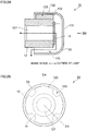
- FIGS. 2A and 2B are diagrams for illustrating a configuration of the ventilating unit 10 to which the exemplary embodiment is applied.
- FIG. 2A is a cross-sectional view in which the ventilating unit 10 is cut along a ventilating direction in a ventilating path 121, which will be described later, and corresponds to the IIA-IIA cross sectional view in FIG. 2B .
- FIG. 2B is a view as viewing FIG. 2A from the IIB direction.
- the ventilating unit 10 of the exemplary embodiment includes a ventilating film 11 in a film shape that performs ventilation between the inside space S and the outside of the vehicle lamp 1. Moreover, the ventilating unit 10 includes a ventilation attachment part 12 in a cylinder shape that holds the ventilating film 11 and is attached to the first opening 2a of the case 2, and a covering part 13 in a bottomed cylinder shape that covers the ventilating film 11 and the ventilation attachment part 12.
- the ventilating film 11 of the exemplary embodiment is a film that prevents liquids, such as water, or solids, such as dust, from entering the inside space S, and allows flow of gases, such as air or water vapor.
- the ventilating film 11 can be configured with a porous film or the like having multiple holes formed by a stretching method, an extraction method or the like.
- a polytetrafluoroethylene (PTFE) porous film can be provided as the porous film used for the ventilating film 11.
- the PTFE porous film is preferable in terms of maintaining a ventilating property even with a small area and having high capability of preventing water, dust or the like from passing through.
- an average pore diameter of the holes formed in the porous film is normally in a range from 0.01 ⁇ m or more to 100 ⁇ m or less, preferably in a range from 0.1 ⁇ m or more to 50 ⁇ m or less, and more preferably in a range from 0.5 ⁇ m or more to 10 ⁇ m or less.
- the average pore diameter of the porous film used as the ventilating film 11 is less than 0.01 ⁇ m, the air is less likely to pass through the ventilating film 11. In this case, for example, when the temperature in the inside space S becomes high and the air in the inside space S expands due to heat generation in the LED 4, the case 2, the cover lens 3 or the like is likely to be broken. On the other hand, when the average pore diameter of the porous film used as the ventilating film 11 exceeds 100 ⁇ m, dust or the like is likely to intrude into the inside space S through the ventilating film 11.
- the thickness of the ventilating film 11 is not particularly limited; however, for example, the thickness can be set in a range from 10 ⁇ m or more to 1000 ⁇ m or less.
- the ventilating unit 10 is likely to be large-sized.
- liquid repellent treatment such as water repellent treatment or oil repellent treatment
- the surface of the ventilating film 11 in particular, the surface facing the outside of the vehicle lamp 1 when the ventilating unit 10 is attached to the first opening 2a of the case 2).
- the liquid repellent treatment for the ventilating film 11 can be performed by coating the surface of the ventilating film 11 with a liquid repellent agent, which has, for example, a compound including a hydrocarbon group saturated with fluoride (perfluoro-alkyl group) in a side chain and has a main chain of acrylic series, methacrylic series, silicone series or the like as a component.
- a liquid repellent agent which has, for example, a compound including a hydrocarbon group saturated with fluoride (perfluoro-alkyl group) in a side chain and has a main chain of acrylic series, methacrylic series, silicone series or the like as a component.
- the method of coating the surface of the ventilating film 11 is not particularly limited; however, for example, gravure coating, spray coating, kiss coating, dipping or the like can be adopted.
- the ventilation attaching part 12 has a cylindrical shape as a whole, and the ventilating path 121 in a columnar shape, through which the air having passed the ventilating film 11 or the air to be discharged from the inside space S passes, is formed inside thereof.
- the ventilating path 121 is, in a state where the ventilating unit 10 is attached to the case 2 (refer to FIG. 1 ) of the vehicle lamp 1 (refer to FIG. 1 ), extending in a direction heading from the outside of the vehicle lamp 1 toward the inside space S. More specifically, of the ventilating path 121, an end portion closer to the inside space S faces toward the dehumidifying unit 20 attached to the case 2 of the vehicle lamp 1.
- the ventilation attaching part 12 includes multiple (in this example, four) protruding parts 122 that protrude from an outer circumferential surface. Each protruding part 122 is provided with the gap 123 with an adjacent protruding part 122.
- the ventilating film 11 is attached to the ventilation attaching part 12 so that, of the ventilating path 121, one end portion positioned closer to the outside of the vehicle lamp 1 is closed.
- the method of attaching the ventilating film 11 to the ventilation attaching part 12 is not particularly limited; however, for example, methods such as thermal fusion bonding, ultrasonic welding, and bonding using a bonding agent, an adhesive agent or the like can be provided.
- the covering part 13 includes a space in a columnar shape formed inside thereof and, as described above, has a bottomed cylindrical shape as a whole. Specifically, the covering part 13 includes a bottom surface 131 in a circular shape and a side surface 132 in a cylindrical shape extending from an outer edge of the bottom surface 131.
- the covering part 13 is attached to an outer circumference of the ventilation attaching part 12 to cover the ventilating film 11 attached to the ventilation attaching part 12.
- adhesion of contamination or the like to the surface of the ventilating film 11 is suppressed, and also, breakage of the ventilating film 11 is suppressed.
- the side surface 132 of the covering part 13 is configured to contact the protruding parts 122 of the ventilation attaching part 12. This causes, in the ventilating unit 10, the covering part 13 to be positioned with respect to the ventilation attaching part 12. Then, in the ventilating unit 10, a predetermined gap is formed between the ventilating film 11 and the bottom surface 131 of the covering part 13.
- the ventilation attaching part 12 and the covering part 13 are configured with, for example, a thermoplastic elastomer, a thermoplastic resin or the like. Note that the ventilation attaching part 12 and the covering part 13 may be configured with the same material, or materials different from each other.
- the ventilating unit 10 of the exemplary embodiment is mounted to the vehicle lamp 1 (refer to FIG. 1 ) by attaching the ventilation attaching part 12 to the first opening 2a (refer to FIG. 1 ) of the case 2 (refer to FIG. 1 ).
- the method of attaching the ventilation attaching part 12 to the first opening 2a of the case 2 is not particularly limited; however, for example, an attaching method that performs thread cutting to the first opening 2a and the ventilation attaching part 12, to thereby screw the ventilation attaching part 12 into the first opening 2a, a method of press fitting the ventilation attaching part 12 into the first opening 2a, or the like can be appropriately adopted.
- the gas flows from the outside of the vehicle lamp 1 toward the inside space S, as indicated by a broken line in FIG. 2A , the gas enters the inside of the ventilating unit 10 through the gap 123 formed between the ventilation attaching part 12 and the covering part 13. Then, the gas entered the ventilating unit 10 passes through the ventilating film 11 from the right toward the left in the figure, and enters the inside space S through the ventilating path 121 formed in the ventilation attaching part 12.
- the ventilating unit 10 of the exemplary embodiment has a function as an internal pressure adjusting member that suppresses pressure fluctuations in the inside space S in the vehicle lamp 1.
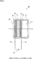
- FIG. 3 is a diagram for illustrating a configuration of the dehumidifying unit 20 to which the exemplary embodiment is applied, and is a cross-sectional view in which the dehumidifying unit 20 is cut along the thickness direction of the electrolysis dehumidifying element 30, which will be described later. Note that FIG. 3 shows the dehumidifying unit 20 shown in FIG. 1 in the state being rotated 90 degrees in the counterclockwise direction.
- the dehumidifying unit 20 of the exemplary embodiment includes the electrolysis dehumidifying element 30 that dehumidifies the inside space S by electrolyzing water vapor or others in the inside space S. Moreover, the dehumidifying unit 20 includes a dehumidification attachment part 21 that holds the electrolysis dehumidifying element 30 and is attached to the second opening 2b of the case 2.
- the dehumidification attachment part 21 a hole 211 extending from the inside space S to the outside of the vehicle lamp 1 is formed, and the electrolysis dehumidifying element 30 is held in the hole 211.
- the dehumidification attachment part 21 is configured with, for example, a thermoplastic elastomer, a thermoplastic resin or the like. Then, the dehumidifying unit 20 of the exemplary embodiment is mounted to the vehicle lamp 1 (refer to FIG. 1 ) by attaching the dehumidification attachment part 21 to the second opening 2b (refer to FIG. 1 ) of the case 2 (refer to FIG. 1 ).
- the method of attaching the dehumidification attachment part 21 to the second opening 2b of the case 2 is not particularly limited; however, for example, an attaching method that performs thread cutting to the second opening 2b and the dehumidification attachment part 21, to thereby screw the dehumidification attachment part 21 into the second opening 2b, a method of press fitting the dehumidification attachment part 21 into the second opening 2b, or the like can be appropriately adopted.
- the dehumidifying unit 20 includes a first conductor wire 25 connected to a first electrode layer 32, which will be described later, of the electrolysis dehumidifying element 30 and a second conductor wire 26 connected to a second electrode layer 33.
- the first conductor wire 25 and the second conductor wire 26 are connected to an external power supply 50 provided outside of the dehumidifying unit 20.
- the dehumidifying unit 20 of the exemplary embodiment performs dehumidification of the inside space S of the vehicle lamp 1 based on the control by the control part 60.
- the electrolysis dehumidifying element 30 of the exemplary embodiment includes an electrolyte layer 31 made of electrolytes, the first electrode layer 32 laminated on one of surfaces of the electrolyte layer 31
- the electrolysis dehumidifying element 30 of the exemplary embodiment includes a configuration in which the first electrode 32, the electrolyte layer 31 and the second electrode layer 32 are laminated in order from the inside space S side.
- the electrolyte layer 31 of the exemplary embodiment has a film-like or plate-like shape.
- the electrolyte layer 31 is configured with electrolytes having protonic conductivity.
- electrolytes constituting the electrolyte layer 31 for example, a fluorine-based proton conducting electrolyte, such as perfluoroalkyl sulfonic acid resin, or a polymer electrolyte resin that introduces a proton conducting group, such as a sulfonic acid group or a phosphoric acid group, into polyether ketone, polyether ether ketone, polyether sulfone or the like can be used.
- the electrolyte layer 31 has a property to adsorb moisture contained in the air (water vapor). Moreover, the electrolyte layer 31 has a property not to allow gases to permeate.
- catalytic layers 311 for promoting an electrolysis reaction in the electrolyte layer 31 are formed on the surfaces of the electrolyte layer 31 (surfaces facing the first electrode layer 32 and the second electrode layer 33).
- the catalytic layer 31 elemental metals of elements of the platinum group, such as Pt, Ru, Rh, Ir, Os or Pd, or alloys containing these elements of the platinum group can be provided. Among them, it is preferable to use Pt having high catalytic activity.
- electrolysis of water in the electrolyte layer 31 is more likely to be facilitated by forming the catalytic layers 311 on the surfaces of the electrolyte layer 31, and therefore, dehumidification of the inside space S is performed more rapidly.
- the first electrode layer 32 and the second electrode layer 33 are used for applying a predetermined voltage to the electrolyte layer 31.
- the first electrode layer 32 is electrically connected to one of the surfaces, which faces toward the inside space S, of the electrolyte layer 31 and operates as an anode.
- the second electrode layer 33 is electrically connected to the other surface (the surface opposite to the one surface to which the first electrode layer 32 is connected) of the electrolyte layer 31 and operates as a cathode.
- the first electrode layer 32 and the second electrode layer 33 are configured with a material having conductivity.
- a metal material in a mesh shape or a fiber shape can be used as the first electrode layer 32.
- moisture (water vapor) in the inside space S is likely to be adsorbed by the electrolyte layer 31 through the first electrode layer 32.
- the metal material in the mesh shape or the fiber shape as the second electrode layer 33 hydrogen, water vapor or others generated by a reduction reaction in the second electrode layer 33, which will be described later, are likely to be discharged to the outside of the vehicle lamp 1 through the second electrode layer 33.
- first electrode layer 32 and the second electrode layer 33 may be configured with metal plates having multiple small holes formed thereon. In this case, by the small holes formed on the metal plates, the ventilating properties of the first electrode layer 32 and the second electrode layer 33 are secured.
- first electrode layer 32 and the second electrode layer 33 may be configured with a porous material having conductivity and ventilating property.
- a porous material for example, a porous carbon sheet holding metal particles can be provided.
- the electrolysis dehumidifying element 30 is attached to the dehumidification attachment part 21 with no gap being created. Moreover, as described above, the electrolysis dehumidifying element 30 of the exemplary embodiment has a property not to allow water vapor, air or others to permeate in a non-energization state. Therefore, the dehumidifying unit 20 of the exemplary embodiment has airtightness between the inside space S and the outside of the vehicle lamp 1 in the non-energization state.
- the vehicle lamp 1 of the exemplary embodiment is configured not to allow gases, such as water vapor or air, to enter the inside space S through the dehumidifying unit 20.
- a DC voltage is applied to the electrolysis dehumidifying element 30 by the external power supply 50 at predetermined timing. Specifically, by the external power supply 50, the DC voltage is applied continuously or intermittently between the first electrode layer 32 and the second electrode layer 33 of the electrolysis dehumidifying element 30 via the first conductor wire 25 and the second conductor wire 26.
- Oxygen generated in the first electrode layer 32 is released from the surface of the first electrode layer 32 to the inside space S.
- proton (hydrogen ion) generated in the first electrode layer 32 moves within the electrolyte layer 31 and reaches the second electrode layer 33.
- water (water vapor) or hydrogen generated in the second electrode layer 33 is released from the surface of the second electrode layer 33 to the outside of the vehicle lamp 1 through the hole 211 in the dehumidification attachment part 21.
- the ventilating unit 10 and the dehumidifying unit 20 are provided at the different positions on the case 2.
- the ventilating unit 10, the LED 4, the dehumidifying unit 20 and the cover lens 3 are arranged in order from an upstream side toward a downstream side in the emission direction of light.
- the ventilating unit 10 and the dehumidifying unit 20 are provided on a vertically lower side of the case 2.
- the vehicle lamp 1 is normally provided with a ventilating means, such as the ventilating unit 10, that performs ventilation between the inside space S and the outside of the vehicle lamp 1.
- a ventilating means such as the ventilating unit 10
- a light source such as the LED 4 provided to the vehicle lamp 1 generates heat and has high temperature when being lighted up. Therefore, when the LED 4 is lighted up in the vehicle lamp 1, the air in the inside space S of the vehicle lamp 1 is warmed.
- an infrared component is normally not contained in the light emitted from the LED 4 and water droplets or the like attached to the cover lens 3 are less likely to be heated, and accordingly, condensation or fogging occurred on the cover lens 3 is less likely to be eliminated.
- a method that discharges the water vapor through the ventilating unit 10 by use of air convection occurring in the inside space S, or the like, can be provided.
- the ventilating unit 10 and the dehumidifying unit 20 attached to different positions of the case 2 the water vapor entered the inside space S is rapidly discharged to the outside of the vehicle lamp 1, and thereby condensation or fogging on the cover lens 3 is suppressed.
- the dehumidifying unit 20 is energized by the external power supply 50 at predetermined timing based on the control by the control part 60, to thereby perform dehumidification of the inside space S.
- a description will be given of a case in which the dehumidifying operation is performed at timing of lighting down the LED 4 as the predetermined timing in the vehicle lamp 1.
- FIG. 4 is a diagram showing a state in which the dehumidifying operation is performed in the vehicle lamp 1 to which the exemplary embodiment is applied.
- a DC voltage is applied to the electrolysis dehumidifying element 30 of the dehumidifying unit 20 by the external power supply 50 (refer to FIG. 3 ) based on the control by the control part 60 (refer to FIG. 1 ) on the timing of lighting down the LED 4.
- the temperature in the inside space S is decreased and the air in the inside space S is contracted, and accordingly, the pressure in the inside space S becomes low as compared to the outside of the vehicle lamp 1. Then, due to the pressure difference between the inside space S and the outside of the vehicle lamp 1, as shown in FIG. 4 , the air of the outside of the vehicle lamp 1 enters the inside space S through the above-described ventilating film 11 (refer to FIG. 2 ) of the ventilating unit 10.
- the ventilating unit 10 is provided on the vertically lower side of the inside space S as compared to the LED 4.
- the air of low temperature entered the inside space S from the ventilating unit 10 moves in the vertically lower side of the inside space S from the rear side to the front side of the vehicle, as shown in FIG. 4 , due to difference in density with the air existed in the inside space S.
- the gap is formed between the support member 5 and the case 2. Consequently, the air entered the inside space S from the ventilating unit 10 moves between the support member 5 and the case 2 from the rear side to the front side of the vehicle.
- a flow path for the air entered the inside space S from the ventilating unit 10 is formed between the support member 5 and the case 2 in the vertically lower portion of the inside space S.
- the dehumidifying unit 20 is mounted to the second opening 2b formed in the vertically lower portion of the case 2, the second opening 2b being closer to the front side of the vehicle than the first opening 2a to which the ventilating unit 10 is mounted.
- the dehumidifying unit 20 is provided on the flow path of the air entered the inside space S from the ventilating unit 10.
- the air entered the inside space S from the ventilating unit 10 moves in the vertically lower portion of the inside space S toward a position facing the dehumidifying unit 20. Then, the water vapor contained in the air entered the inside space S from the ventilating unit 10 is adsorbed by the electrolysis dehumidifying element 30 (refer to FIG. 3 ) of the dehumidifying unit 20.
- the dehumidifying unit 20 is provided on a side close to the rear side of the vehicle and close to the ventilating unit 10 as compared to the cover lens 3.
- the vehicle lamp 1 of the exemplary embodiment includes a guide plate 9 that guides the air entered the inside space S from the ventilating unit 10 toward the dehumidifying unit 20.
- the air entered the inside space S in the vehicle lamp 1 changes the traveling direction thereof by butting against the guide plate 9, and is guided toward the dehumidifying unit 20. Consequently, the water vapor contained in the air becomes more likely to be adsorbed by the electrolysis dehumidifying element 30 of the dehumidifying unit 20, and becomes more likely to be discharged to the outside of the vehicle lamp 1 by the dehumidifying unit 20.
- the guide plate 9 which is a separate body from the support member 5 or the case 2, was provided; however, it may be possible to have a configuration that guides the air entered the inside space S from the ventilating unit 10 toward the dehumidifying unit 20 by, for example, changing the shape of the support member 5 or the case 2. In this case, it is unnecessary to separately provide the guide plate 9; therefore, it becomes possible to reduce the number of components of the vehicle lamp 1, and manufacturing of the vehicle lamp 1 becomes simplified.
- FIGS. 5A and 5B are diagrams showing other examples of the vehicle lamp 1 including the ventilating unit 10 and the dehumidifying unit 20.
- the ventilating unit 10 is provided on a vertically upper side of the case 2, and the dehumidifying unit 20 is provided at a position facing a vertically lower side of the ventilating unit 10 in the case 2.
- the air of low temperature having entered the inside space S from the outside of the vehicle lamp 1 through the ventilating unit 10 moves to the vertically lower side to head for the dehumidifying unit 20.
- the dehumidifying unit 20 is provided on the flow path of the air entered the inside space S through the ventilating unit 10.
- the ventilating unit 10 and the dehumidifying unit 20 as shown in FIG. 5A , the water vapor contained in the air entered the inside space S from the ventilating unit 10 becomes likely to be discharged to the outside of the vehicle lamp 1 through the dehumidifying unit 20. As a result, condensation or fogging on the cover lens 3 is suppressed.
- both ventilating unit 10 and dehumidifying unit 20 are provided on the vertically lower side of the case 2.
- the ventilating unit 10 is provided close to the front side of the vehicle (that is, close to the cover lens 3) as compared to the dehumidifying unit 20.
- the guide plate 9 extending from the front side to the rear side of the vehicle is provided to interrupt between the ventilating unit 10 and the cover lens 3.
- the traveling direction of the air entered the inside space S from the outside of the vehicle lamp 1 through the ventilating unit 10 is changed by the guide plate 9, and thereby the air moves toward the dehumidifying unit 20.
- the dehumidifying unit 20 is provided on the flow path of the air entered the inside space S through the ventilating unit 10.
- the ventilating unit 10 and the dehumidifying unit 20 as shown in FIG. 5B , the air entered from the ventilating unit 10 becomes likely to be reached to the dehumidifying unit 20 before reaching the cover lens 3. Consequently, the water vapor contained in the air entered the inside space S from the ventilating unit 10 becomes likely to be discharged to the outside of the vehicle lamp 1 by the dehumidifying unit 20. As a result, condensation or fogging on the cover lens 3 is suppressed.
- the ventilating unit 10 of the exemplary embodiment is provided to suppresses pressure fluctuations in the inside space S in the vehicle lamp 1.
- the water vapor entered the inside space S is discharged to the outside of the vehicle lamp 1 by the dehumidifying unit 20, and accordingly, it is unnecessary to discharge the water vapor by the ventilating unit 10.
- the ventilating unit 10 may have at least a size that allows air for eliminating a pressure difference to pass through when the pressure difference occurs between the inside space S and the outside of the vehicle lamp 1. In the vehicle lamp 1 of the exemplary embodiment, this makes it possible to downsize the ventilating unit 10, as compared to a case in which the water vapor is discharged by the ventilating unit 10.
- the ventilating unit 10 of the exemplary embodiment has a configuration that attach the ventilating film 11 to the case 2 of the vehicle lamp 1 via the ventilation attaching part 12.
- the configuration of the ventilating unit 10 is not particularly limited.
- the configuration of the dehumidifying unit 20 is also not particularly limited, and it may be possible to configure the dehumidifying unit 20 by directly attaching the electrolysis dehumidifying element 30 to the second opening 2b of the case 2. Still further, in the dehumidifying unit 20, it may be possible to provide a protecting member or others for protecting the electrolysis dehumidifying element 30 on the surface of the electrolysis dehumidifying element 30.
- the dehumidifying operations may be constantly performed in the vehicle lamp 1 by, for example, energizing the dehumidifying unit 20 at all times. In this case, regardless of the environment in which the vehicle lamp 1 is placed or the status of the vehicle, the inside space S is always dehumidified, and condensation or fogging on the cover lens 3 is suppressed.
- the dehumidifying operations in the inside space S may be performed by energizing the dehumidifying unit 20 at, for example, a predetermined time, such as early morning, based on the time measured by a timer or others.
- the dehumidifying operations may be performed by energizing the dehumidifying unit 20 when a predetermined operation, such as an operation of opening a door, is carried out in the vehicle to which the vehicle lamp 1 is mounted.
- the vehicle lamp 1 it may be possible to provide a detection sensor that detects humidity in the inside space S in the vehicle lamp 1 or humidity of the outside of the vehicle lamp 1, and energize the dehumidifying unit 20 to perform the dehumidifying operations when the humidity detected by the detection sensor exceeds a predetermined value.
- the vehicle lamp 1 it may be possible to provide a raindrop sensor to the vehicle to which the vehicle lamp 1 is mounted, and energize the dehumidifying unit 20 to perform the dehumidifying operations when rainfall is detected.
- the vehicle lamp 1 has been taken as an example of the dehumidifying device that dehumidifies the inside space S by the ventilating unit 10 and the dehumidifying unit 20; however, an object to which the present invention is applied is not limited to the vehicle lamp 1.
- the present invention can be applied to an optical appliance, such as a monitoring camera, with which condensation or fogging on a lens is likely to become problematic.
Landscapes
- Engineering & Computer Science (AREA)
- General Engineering & Computer Science (AREA)
- Chemical & Material Sciences (AREA)
- Analytical Chemistry (AREA)
- General Chemical & Material Sciences (AREA)
- Oil, Petroleum & Natural Gas (AREA)
- Chemical Kinetics & Catalysis (AREA)
- Arrangement Of Elements, Cooling, Sealing, Or The Like Of Lighting Devices (AREA)
- Non-Portable Lighting Devices Or Systems Thereof (AREA)
- Drying Of Gases (AREA)
- Physics & Mathematics (AREA)
- Microelectronics & Electronic Packaging (AREA)
- Optics & Photonics (AREA)
Abstract
Description
- The present invention relates to a dehumidifying device and a lamp.
- Conventionally, in lamps, such as vehicle lamps, or optical appliances, such as monitoring cameras, condensation of moisture in the inside of a housing containing components, such as a light source, and fogging of a lens associated with the condensation have been a problem.
- In
Patent Document 1, there is disclosed a technique in which a casing is provided with multiple ventilation holes for preventing condensation in the inside of the housing in a vehicle lamp, to thereby perform ventilation in the inside of the housing by air convection generated in the inside of the housing. - Patent Document 1: National Publication of International Patent Application No.
2011-519136 - An object of the present invention is to provide a dehumidifying device and a lamp capable of rapidly discharging water vapor that has entered inside of a housing to an outside of the housing.
- Under such an object, the present invention provides a dehumidifying device (1) including: a ventilating member (11) that is provided at a first position (2a) of a housing (2, 3) that is closed, the ventilating member preventing a liquid and a solid from entering inside (S) of the housing and circulating a gas between the inside and outside of the housing; and an electrolysis dehumidifying element (30) that is provided at a second position (2b) of the housing different from the first position, the electrolysis dehumidifying element discharging water vapor inside of the housing to the outside of the housing by electrolysis.
- Here, the electrolysis dehumidifying element (30) is provided on a flow path of a gas entered the inside (S) of the housing (2, 3) from the ventilating member (11).
- Moreover, the dehumidifying device further includes a guiding unit (9) that guides a gas entered the inside (S) of the housing (2, 3) through the ventilating member (11) to the electrolysis dehumidifying element (30).
- Further, the electrolysis dehumidifying element (30) is provided on a vertically lower side in the housing (2, 3).
- Further, from another standpoint, the present invention provides a lamp (1) including: a light source (4); a housing (2) that contains the light source; a lens (3) that outputs light from the light source to outside of the housing; a ventilating member (11) that is provided at a first position (2a) of the housing that is closed, the ventilating member preventing a liquid and a solid from entering inside (S) of the housing and circulating a gas between the inside and outside of the housing; and an electrolysis dehumidifying element (30) that is provided at a second position (2b) of the housing different from the first position, the electrolysis dehumidifying element discharging water vapor inside of the housing to the outside of the housing by electrolysis.
- Here, the ventilating member (11) is provided at a position that allows most of the gas entered from the ventilating member to reach the electrolysis dehumidifying element (30) before reaching the lens (3).
- Moreover, the electrolysis dehumidifying element (30) is provided on a vertically lower side than the light source (4).
- Note that the above signs in this section are provided for exemplification in describing the present invention, and the present invention is not subjected to limited interpretation by these signs.
- According to the present invention, it is possible to provide a dehumidifying device and a lamp capable of rapidly discharging water vapor that has entered inside of a housing to an outside of the housing.
-
-
FIG. 1 is a diagram showing an overall configuration of a vehicle lamp to which an exemplary embodiment is applied; -
FIGS. 2A and 2B are diagrams for illustrating a configuration of a ventilating unit to which the exemplary embodiment is applied; -
FIG. 3 is a diagram for illustrating a configuration of a dehumidifying unit to which the exemplary embodiment is applied; -
FIG. 4 is a diagram showing a state in which a dehumidifying operation is performed in the vehicle lamp to which the exemplary embodiment is applied; and -
FIGS. 5A and 5B are diagrams showing other examples of a vehicle lamp including a ventilating unit and a dehumidifying unit. - Hereinafter, an exemplary embodiment according to the present invention will be described in detail with reference to attached drawings.
-
FIG. 1 is a diagram showing an overall configuration of avehicle lamp 1 to which the exemplary embodiment is applied. - The
vehicle lamp 1 to which the exemplary embodiment is applied is used as a head lamp, a rear lamp, a brake lamp, a fog lamp, a direction indicator lamp, a taxing lamp, a parking lamp, etc., of various kinds of vehicles typified by, for example, automobiles. InFIG. 1 , a head lamp is shown as an example of these lamps. Here,FIG. 1 is a cross-sectional view in which thevehicle lamp 1 is cut along a traveling direction of a vehicle, and the left side inFIG. 1 corresponds to a front side of the vehicle and the right side corresponds to a rear side of the vehicle. - The
vehicle lamp 1 shown inFIG. 1 includes acase 2 that contains and protects components, such as anLED 4 to be described later, and acover lens 3 that is attached to thecase 2 and irradiates the outside of thevehicle lamp 1 with light from theLED 4. In thevehicle lamp 1, an inside space S, which is closed off from the outside, is formed by thecase 2 and thecover lens 3. This increases the waterproofing property and dust-proofing property for each component contained in thecase 2. Moreover, in the exemplary embodiment, a housing of thevehicle lamp 1 is configured with thecase 2 and thecover lens 3. - In addition, the
vehicle lamp 1 includes aventilating unit 10 that performs ventilation between the inside space S and the outside of thevehicle lamp 1. Further, thevehicle lamp 1 includes a dehumidifyingunit 20 that discharges water vapor or the like in the inside space S to the outside of thevehicle lamp 1, to thereby dehumidify the inside space S. - In the
case 2, a first opening 2a and a second opening 2b, which are opened from the inside space S toward the outside of thevehicle lamp 1, are formed. - Here, the first opening 2a and the second opening 2b are formed at different positions of the
case 2. Specifically, thefirst opening 2a is formed at a position in a vertically lower portion and on the side closer to the rear side of the vehicle in thecase 2. On the other hand, the second opening 2b is formed at a position in a vertically lower portion and on the side, as compared to thefirst opening 2a, closer to the front side of the vehicle in thecase 2. In this example, the position where thefirst opening 2a is formed corresponds to a first position, and the position where thesecond opening 2b is formed corresponds to a second position. - Then, in the
vehicle lamp 1 of the exemplary embodiment, theventilating unit 10 is attached to thefirst opening 2a of thecase 2. Moreover, thedehumidifying unit 20 is attached to the second opening 2b of thecase 2. To additionally describe, in thevehicle lamp 1 of the exemplary embodiment, theventilating unit 10 and thedehumidifying unit 20 are attached to the positions on thecase 2 that are different from each other. - Further, the
vehicle lamp 1 includes the LED (Light Emitting Diode) 4, as an example of a light source, that emits light, and asupport member 5 that supports theLED 4 and diffuses heat generated in theLED 4. Moreover, thevehicle lamp 1 includes aprojector lens 6 that projects the light emitted from theLED 4 toward the front and a reflectingmirror 7 that reflects the light emitted from theLED 4 toward theprojector lens 6. Then, in thevehicle lamp 1, theLED 4, thesupport member 5, theprojector lens 6 and the reflectingmirror 7 are provided in the inside space S. Moreover, in thevehicle lamp 1, a gap is formed between thesupport member 5 and thecase 2, as shown inFIG. 1 . - In the
vehicle lamp 1 shown inFIG. 1 , theLED 4 emits light toward the front of the vehicle. Then, the light emitted from theLED 4 passes through theprojector lens 6, and thereafter, the light is emitted toward the outside of thevehicle lamp 1 via thecover lens 3. - Still further, the
vehicle lamp 1 includes aguide plate 9, as an example of a guide unit, that guides air entered the inside space S through theventilating unit 10. As shown inFIG. 1 , theguide plate 9 has a flat-plate shape, and is provided in the inside space S to extend from thesupport member 5 toward thecover lens 3. Moreover, as shown inFIG. 1 , one of surfaces of theguide plate 9 faces thedehumidifying unit 20 attached to thecase 2. - Note that guidance of the air by the
guide plate 9 will be described in detail at a later stage. - Moreover, in the
vehicle lamp 1 of the exemplary embodiment, lighting up and lighting down of theLED 4, a dehumidifying operation by thedehumidifying unit 20, and the like are performed based on control by acontrol part 60. - Subsequently, the
ventilating unit 10 of the exemplary embodiment will be described.FIGS. 2A and 2B are diagrams for illustrating a configuration of theventilating unit 10 to which the exemplary embodiment is applied.FIG. 2A is a cross-sectional view in which theventilating unit 10 is cut along a ventilating direction in aventilating path 121, which will be described later, and corresponds to the IIA-IIA cross sectional view inFIG. 2B . Moreover,FIG. 2B is a view as viewingFIG. 2A from the IIB direction. - As shown in
FIG. 2A and the above-describedFIG. 1 , the ventilatingunit 10 of the exemplary embodiment includes a ventilatingfilm 11 in a film shape that performs ventilation between the inside space S and the outside of thevehicle lamp 1. Moreover, the ventilatingunit 10 includes aventilation attachment part 12 in a cylinder shape that holds the ventilatingfilm 11 and is attached to thefirst opening 2a of thecase 2, and a coveringpart 13 in a bottomed cylinder shape that covers the ventilatingfilm 11 and theventilation attachment part 12. - The ventilating
film 11 of the exemplary embodiment is a film that prevents liquids, such as water, or solids, such as dust, from entering the inside space S, and allows flow of gases, such as air or water vapor. The ventilatingfilm 11 can be configured with a porous film or the like having multiple holes formed by a stretching method, an extraction method or the like. As the porous film used for the ventilatingfilm 11, for example, a polytetrafluoroethylene (PTFE) porous film can be provided. The PTFE porous film is preferable in terms of maintaining a ventilating property even with a small area and having high capability of preventing water, dust or the like from passing through. - Moreover, when the porous film is used as the ventilating
film 11 of the exemplary embodiment, an average pore diameter of the holes formed in the porous film is normally in a range from 0.01 µm or more to 100 µm or less, preferably in a range from 0.1 µm or more to 50 µm or less, and more preferably in a range from 0.5 µm or more to 10 µm or less. - When the average pore diameter of the porous film used as the ventilating
film 11 is less than 0.01 µm, the air is less likely to pass through the ventilatingfilm 11. In this case, for example, when the temperature in the inside space S becomes high and the air in the inside space S expands due to heat generation in theLED 4, thecase 2, thecover lens 3 or the like is likely to be broken. On the other hand, when the average pore diameter of the porous film used as the ventilatingfilm 11 exceeds 100 µm, dust or the like is likely to intrude into the inside space S through the ventilatingfilm 11. - The thickness of the ventilating
film 11 is not particularly limited; however, for example, the thickness can be set in a range from 10 µm or more to 1000 µm or less. - When the thickness of the ventilating
film 11 is extremely small, strength of the ventilatingfilm 11 is likely to be reduced. Moreover, when the thickness of the ventilatingfilm 11 is extremely large, the ventilatingunit 10 is likely to be large-sized. - Moreover, it is preferable to apply liquid repellent treatment, such as water repellent treatment or oil repellent treatment to the surface of the ventilating film 11 (in particular, the surface facing the outside of the
vehicle lamp 1 when the ventilatingunit 10 is attached to thefirst opening 2a of the case 2). By applying the liquid repellent treatment to the ventilatingfilm 11, adhesion of contamination or the like to the ventilatingfilm 11 is suppressed. As a result, clogging of the ventilatingfilm 11 is suppressed, and accordingly, deterioration of ventilating property caused by the ventilatingunit 10 is suppressed. - Note that the liquid repellent treatment for the ventilating
film 11 can be performed by coating the surface of the ventilatingfilm 11 with a liquid repellent agent, which has, for example, a compound including a hydrocarbon group saturated with fluoride (perfluoro-alkyl group) in a side chain and has a main chain of acrylic series, methacrylic series, silicone series or the like as a component. The method of coating the surface of the ventilatingfilm 11 is not particularly limited; however, for example, gravure coating, spray coating, kiss coating, dipping or the like can be adopted. - The
ventilation attaching part 12 has a cylindrical shape as a whole, and theventilating path 121 in a columnar shape, through which the air having passed theventilating film 11 or the air to be discharged from the inside space S passes, is formed inside thereof. The ventilatingpath 121 is, in a state where the ventilatingunit 10 is attached to the case 2 (refer toFIG. 1 ) of the vehicle lamp 1 (refer toFIG. 1 ), extending in a direction heading from the outside of thevehicle lamp 1 toward the inside space S. More specifically, of theventilating path 121, an end portion closer to the inside space S faces toward thedehumidifying unit 20 attached to thecase 2 of thevehicle lamp 1. - Moreover, the
ventilation attaching part 12 includes multiple (in this example, four) protrudingparts 122 that protrude from an outer circumferential surface. Each protrudingpart 122 is provided with thegap 123 with an adjacent protrudingpart 122. - Then, the ventilating
film 11 is attached to theventilation attaching part 12 so that, of theventilating path 121, one end portion positioned closer to the outside of thevehicle lamp 1 is closed. The method of attaching the ventilatingfilm 11 to theventilation attaching part 12 is not particularly limited; however, for example, methods such as thermal fusion bonding, ultrasonic welding, and bonding using a bonding agent, an adhesive agent or the like can be provided. - The covering
part 13 includes a space in a columnar shape formed inside thereof and, as described above, has a bottomed cylindrical shape as a whole. Specifically, the coveringpart 13 includes abottom surface 131 in a circular shape and aside surface 132 in a cylindrical shape extending from an outer edge of thebottom surface 131. - The covering
part 13 is attached to an outer circumference of theventilation attaching part 12 to cover theventilating film 11 attached to theventilation attaching part 12. By the coveringpart 13, adhesion of contamination or the like to the surface of the ventilatingfilm 11 is suppressed, and also, breakage of the ventilatingfilm 11 is suppressed. - In the ventilating
unit 10, theside surface 132 of the coveringpart 13 is configured to contact the protrudingparts 122 of theventilation attaching part 12. This causes, in the ventilatingunit 10, the coveringpart 13 to be positioned with respect to theventilation attaching part 12. Then, in the ventilatingunit 10, a predetermined gap is formed between the ventilatingfilm 11 and thebottom surface 131 of the coveringpart 13. - The
ventilation attaching part 12 and the coveringpart 13 are configured with, for example, a thermoplastic elastomer, a thermoplastic resin or the like. Note that theventilation attaching part 12 and the coveringpart 13 may be configured with the same material, or materials different from each other. - Then, the ventilating
unit 10 of the exemplary embodiment is mounted to the vehicle lamp 1 (refer toFIG. 1 ) by attaching theventilation attaching part 12 to thefirst opening 2a (refer toFIG. 1 ) of the case 2 (refer toFIG. 1 ). Note that the method of attaching theventilation attaching part 12 to thefirst opening 2a of thecase 2 is not particularly limited; however, for example, an attaching method that performs thread cutting to thefirst opening 2a and theventilation attaching part 12, to thereby screw theventilation attaching part 12 into thefirst opening 2a, a method of press fitting theventilation attaching part 12 into thefirst opening 2a, or the like can be appropriately adopted. - Subsequently, operations of the ventilating
unit 10 will be described. In the exemplary embodiment, when a pressure difference occurs between the outside of thevehicle lamp 1 and the inside space S of thevehicle lamp 1, a gas flows through the ventilatingunit 10 from the outside of thevehicle lamp 1 toward the inside space S, or, from the inside space S toward the outside of thevehicle lamp 1. - For example, when a gas flows from the outside of the
vehicle lamp 1 toward the inside space S, as indicated by a broken line inFIG. 2A , the gas enters the inside of the ventilatingunit 10 through thegap 123 formed between theventilation attaching part 12 and the coveringpart 13. Then, the gas entered the ventilatingunit 10 passes through the ventilatingfilm 11 from the right toward the left in the figure, and enters the inside space S through the ventilatingpath 121 formed in theventilation attaching part 12. - On the other hand, when a gas flows from the inside space S toward the outside of the
vehicle lamp 1, as indicated by the broken line inFIG. 2A , the gas moves through the ventilatingpath 121 formed in theventilation attaching part 12, and thereafter, passes through the ventilatingfilm 11 from the left toward the right in the figure. Then, the gas passed through the ventilatingfilm 11 passes thegap 123 formed between theventilation attaching part 12 and the coveringpart 13, to be discharged to the outside of thevehicle lamp 1. - This eliminates the pressure difference occurred between the outside of the
vehicle lamp 1 and the inside space S, and thereby breakage of thecase 2 or thecover lens 3 of thevehicle lamp 1 is suppressed. To put it another way, the ventilatingunit 10 of the exemplary embodiment has a function as an internal pressure adjusting member that suppresses pressure fluctuations in the inside space S in thevehicle lamp 1. - Subsequently, the
dehumidifying unit 20 of the exemplary embodiment will be described.FIG. 3 is a diagram for illustrating a configuration of thedehumidifying unit 20 to which the exemplary embodiment is applied, and is a cross-sectional view in which thedehumidifying unit 20 is cut along the thickness direction of theelectrolysis dehumidifying element 30, which will be described later. Note thatFIG. 3 shows thedehumidifying unit 20 shown inFIG. 1 in the state being rotated 90 degrees in the counterclockwise direction. - The
dehumidifying unit 20 of the exemplary embodiment includes theelectrolysis dehumidifying element 30 that dehumidifies the inside space S by electrolyzing water vapor or others in the inside space S. Moreover, thedehumidifying unit 20 includes adehumidification attachment part 21 that holds theelectrolysis dehumidifying element 30 and is attached to thesecond opening 2b of thecase 2. - In the
dehumidification attachment part 21, ahole 211 extending from the inside space S to the outside of thevehicle lamp 1 is formed, and theelectrolysis dehumidifying element 30 is held in thehole 211. Moreover, thedehumidification attachment part 21 is configured with, for example, a thermoplastic elastomer, a thermoplastic resin or the like. Then, thedehumidifying unit 20 of the exemplary embodiment is mounted to the vehicle lamp 1 (refer toFIG. 1 ) by attaching thedehumidification attachment part 21 to thesecond opening 2b (refer toFIG. 1 ) of the case 2 (refer toFIG. 1 ). Note that the method of attaching thedehumidification attachment part 21 to thesecond opening 2b of thecase 2 is not particularly limited; however, for example, an attaching method that performs thread cutting to thesecond opening 2b and thedehumidification attachment part 21, to thereby screw thedehumidification attachment part 21 into thesecond opening 2b, a method of press fitting thedehumidification attachment part 21 into thesecond opening 2b, or the like can be appropriately adopted. - Still further, the
dehumidifying unit 20 includes afirst conductor wire 25 connected to afirst electrode layer 32, which will be described later, of theelectrolysis dehumidifying element 30 and asecond conductor wire 26 connected to asecond electrode layer 33. Thefirst conductor wire 25 and thesecond conductor wire 26 are connected to anexternal power supply 50 provided outside of thedehumidifying unit 20. - Then, the
dehumidifying unit 20 of the exemplary embodiment performs dehumidification of the inside space S of thevehicle lamp 1 based on the control by thecontrol part 60. - The
electrolysis dehumidifying element 30 of the exemplary embodiment includes anelectrolyte layer 31 made of electrolytes, thefirst electrode layer 32 laminated on one of surfaces of theelectrolyte layer 31 - (the surface facing toward the inside space S when the
dehumidifying unit 20 is attached to thesecond opening 2b of the case 2), and thesecond electrode layer 33 laminated on the other surface of the electrolyte layer 31 (the surface opposite to the one of surfaces). This brings theelectrolyte layer 31 into a state being sandwiched by thefirst electrode layer 32 and thesecond electrode layer 33. To put it another way, theelectrolysis dehumidifying element 30 of the exemplary embodiment includes a configuration in which thefirst electrode 32, theelectrolyte layer 31 and thesecond electrode layer 32 are laminated in order from the inside space S side. - The
electrolyte layer 31 of the exemplary embodiment has a film-like or plate-like shape. - Moreover, the
electrolyte layer 31 is configured with electrolytes having protonic conductivity. As the electrolytes constituting theelectrolyte layer 31, for example, a fluorine-based proton conducting electrolyte, such as perfluoroalkyl sulfonic acid resin, or a polymer electrolyte resin that introduces a proton conducting group, such as a sulfonic acid group or a phosphoric acid group, into polyether ketone, polyether ether ketone, polyether sulfone or the like can be used. - The
electrolyte layer 31 has a property to adsorb moisture contained in the air (water vapor). Moreover, theelectrolyte layer 31 has a property not to allow gases to permeate. - Further, on the surfaces of the electrolyte layer 31 (surfaces facing the
first electrode layer 32 and the second electrode layer 33),catalytic layers 311 for promoting an electrolysis reaction in theelectrolyte layer 31 are formed. As thecatalytic layer 311, elemental metals of elements of the platinum group, such as Pt, Ru, Rh, Ir, Os or Pd, or alloys containing these elements of the platinum group can be provided. Among them, it is preferable to use Pt having high catalytic activity. - In the
electrolysis dehumidifying element 30 of the exemplary embodiment, electrolysis of water in theelectrolyte layer 31 is more likely to be facilitated by forming thecatalytic layers 311 on the surfaces of theelectrolyte layer 31, and therefore, dehumidification of the inside space S is performed more rapidly. - The
first electrode layer 32 and thesecond electrode layer 33 are used for applying a predetermined voltage to theelectrolyte layer 31. In theelectrolysis dehumidifying element 30 of the exemplary embodiment, thefirst electrode layer 32 is electrically connected to one of the surfaces, which faces toward the inside space S, of theelectrolyte layer 31 and operates as an anode. Moreover, thesecond electrode layer 33 is electrically connected to the other surface (the surface opposite to the one surface to which thefirst electrode layer 32 is connected) of theelectrolyte layer 31 and operates as a cathode. - The
first electrode layer 32 and thesecond electrode layer 33 are configured with a material having conductivity. As thefirst electrode layer 32 and thesecond electrode layer 33, for example, a metal material in a mesh shape or a fiber shape can be used. By adopting the metal material in the mesh shape or the fiber shape as thefirst electrode layer 32, moisture (water vapor) in the inside space S is likely to be adsorbed by theelectrolyte layer 31 through thefirst electrode layer 32. Moreover, by adopting the metal material in the mesh shape or the fiber shape as thesecond electrode layer 33, hydrogen, water vapor or others generated by a reduction reaction in thesecond electrode layer 33, which will be described later, are likely to be discharged to the outside of thevehicle lamp 1 through thesecond electrode layer 33. - Moreover, the
first electrode layer 32 and thesecond electrode layer 33 may be configured with metal plates having multiple small holes formed thereon. In this case, by the small holes formed on the metal plates, the ventilating properties of thefirst electrode layer 32 and thesecond electrode layer 33 are secured. - Further, the
first electrode layer 32 and thesecond electrode layer 33 may be configured with a porous material having conductivity and ventilating property. As such a porous material, for example, a porous carbon sheet holding metal particles can be provided. - Here, in the
dehumidifying unit 20 of the exemplary embodiment, theelectrolysis dehumidifying element 30 is attached to thedehumidification attachment part 21 with no gap being created. Moreover, as described above, theelectrolysis dehumidifying element 30 of the exemplary embodiment has a property not to allow water vapor, air or others to permeate in a non-energization state. Therefore, thedehumidifying unit 20 of the exemplary embodiment has airtightness between the inside space S and the outside of thevehicle lamp 1 in the non-energization state. - To put it another way, the
vehicle lamp 1 of the exemplary embodiment is configured not to allow gases, such as water vapor or air, to enter the inside space S through thedehumidifying unit 20. - Subsequently, operations of the
dehumidifying unit 20 will be described. In thedehumidifying unit 20 of the exemplary embodiment, based on the control by the control part 60 (refer toFIG. 1 ), a DC voltage is applied to theelectrolysis dehumidifying element 30 by theexternal power supply 50 at predetermined timing. Specifically, by theexternal power supply 50, the DC voltage is applied continuously or intermittently between thefirst electrode layer 32 and thesecond electrode layer 33 of theelectrolysis dehumidifying element 30 via thefirst conductor wire 25 and thesecond conductor wire 26. - Consequently, in the
first electrode layer 32 operating as the anode, water supplied from the inside space S or the like is electrolyzed as shown in the following reaction formula (1). In other words, in thefirst electrode layer 32, water (H2O) is electrolyzed to generate proton (hydrogen ion H+) and oxygen (O2).
- Oxygen generated in the
first electrode layer 32 is released from the surface of thefirst electrode layer 32 to the inside space S. - Moreover, proton (hydrogen ion) generated in the
first electrode layer 32 moves within theelectrolyte layer 31 and reaches thesecond electrode layer 33. - In the
second electrode layer 33 operating as the cathode, proton (hydrogen ion) supplied from thefirst electrode layer 32 through theelectrolyte layer 31 is subjected to the reduction reaction with oxygen contained in air, and thereby water (water vapor) is generated as shown in the reaction formula (2).
- Moreover, in the
second electrode layer 33, proton (hydrogen ion) supplied from thefirst electrode layer 32 through theelectrolyte layer 31 is directly reduced, and thereby hydrogen is generated in some cases as shown in the reaction formula (3).
- Then, water (water vapor) or hydrogen generated in the
second electrode layer 33 is released from the surface of thesecond electrode layer 33 to the outside of thevehicle lamp 1 through thehole 211 in thedehumidification attachment part 21. - As described above, in the
vehicle lamp 1 of the exemplary embodiment, the ventilatingunit 10 and thedehumidifying unit 20 are provided at the different positions on thecase 2. - Moreover, in terms of the emission direction of light from the
LED 4 of thevehicle lamp 1, in the exemplary embodiment, the ventilatingunit 10, theLED 4, thedehumidifying unit 20 and thecover lens 3 are arranged in order from an upstream side toward a downstream side in the emission direction of light. - Further, in the state where the
vehicle lamp 1 is mounted to the vehicle, in thevehicle lamp 1 of the exemplary embodiment, the ventilatingunit 10 and thedehumidifying unit 20 are provided on a vertically lower side of thecase 2. - By the way, conventionally, in the
vehicle lamp 1, such as a head lamp, condensation or fogging of the cover lens 3 (a phenomenon in which thecover lens 3 becomes white and cloudy due to attachment of minute water droplets) caused by increase of humidity in the inside space S has been a problem. As the method of suppressing increase of humidity in the inside space S of thevehicle lamp 1, sealing of the inside space S of thevehicle lamp 1 with thecase 2 and thecover lens 3 is most effective. However, since plastic or others constituting thecase 2 or thecover lens 3 have hygroscopicity, it is impossible to completely suppress entry of moisture to the inside space S. - Moreover, in the case where the inside space S is sealed by the
case 2 and thecover lens 3 in thevehicle lamp 1, when the pressure in the inside space S is sharply increased due to expansion of the air in the inside space S or the pressure in the inside space S is sharply decreased due to contraction of the air in the inside space S, there is a possibility that thecase 2 or thecover lens 3 is broken. - Consequently, for suppressing rapid fluctuations of pressure in the inside space S, the
vehicle lamp 1 is normally provided with a ventilating means, such as the ventilatingunit 10, that performs ventilation between the inside space S and the outside of thevehicle lamp 1. - By the way, in general, a light source, such as the
LED 4, provided to thevehicle lamp 1 generates heat and has high temperature when being lighted up. Therefore, when theLED 4 is lighted up in thevehicle lamp 1, the air in the inside space S of thevehicle lamp 1 is warmed. - Thereafter, when the
LED 4 is lighted down, heat generation in theLED 4 is stopped, and the warmed air in the inside space S is cooled and contracted. With this, the pressure in the inside space S becomes temporarily low as compared to the outside of thevehicle lamp 1. As a result, in thevehicle lamp 1 including the ventilatingunit 10, in response to the pressure difference between the outside of thevehicle lamp 1 and the inside space S, the air enters the inside space S from the outside of thevehicle lamp 1 through the ventilatingunit 10. - Here, when the humidity of the outside of the
vehicle lamp 1, humid air containing water vapor enters the inside space S through the ventilatingunit 10. Then, when the temperature in the inside space S falls below the dew point, condensation or fogging occurs on thecover lens 3. - In particular, for example, when the
cover lens 3 is cooled from the outside by raindrops in rainy weather, or, when thevehicle lamp 1 is left under a low-temperature condition for a long time, since the water vapor entered the inside space S is cooled by contacting thecover lens 3, condensation or fogging is more likely to occur on thecover lens 3. - Moreover, when the
LED 4 is used as the light source, an infrared component is normally not contained in the light emitted from theLED 4 and water droplets or the like attached to thecover lens 3 are less likely to be heated, and accordingly, condensation or fogging occurred on thecover lens 3 is less likely to be eliminated. - To suppress condensation or fogging on the
cover lens 3, it is desirable to rapidly discharge the water vapor entered the inside space S to the outside of thevehicle lamp 1. - As the method of discharging the water vapor entered the inside space S to the outside of the
vehicle lamp 1, for example, a method that discharges the water vapor through the ventilatingunit 10 by use of air convection occurring in the inside space S, or the like, can be provided. - However, in the method that discharges the water vapor through the ventilating
unit 10 by use of the air convection, there is a possibility that difficulty is created in discharging the water vapor sufficiently depending on, for example, relations of pressure and temperature between the inside space S and the outside of thevehicle lamp 1, the amount of water vapor entered the inside space S, or others. In this case, condensation or fogging is likely to occur on thecover lens 3. - For this, in the
vehicle lamp 1 of the exemplary embodiment, by the ventilatingunit 10 and thedehumidifying unit 20 attached to different positions of thecase 2, the water vapor entered the inside space S is rapidly discharged to the outside of thevehicle lamp 1, and thereby condensation or fogging on thecover lens 3 is suppressed. - Subsequently, dehumidifying operations in the
vehicle lamp 1 of the exemplary embodiment will be described. - In the
vehicle lamp 1 of the exemplary embodiment, thedehumidifying unit 20 is energized by theexternal power supply 50 at predetermined timing based on the control by thecontrol part 60, to thereby perform dehumidification of the inside space S. Here, a description will be given of a case in which the dehumidifying operation is performed at timing of lighting down theLED 4 as the predetermined timing in thevehicle lamp 1.FIG. 4 is a diagram showing a state in which the dehumidifying operation is performed in thevehicle lamp 1 to which the exemplary embodiment is applied. - In the
vehicle lamp 1 of the exemplary embodiment, a DC voltage is applied to theelectrolysis dehumidifying element 30 of thedehumidifying unit 20 by the external power supply 50 (refer toFIG. 3 ) based on the control by the control part 60 (refer toFIG. 1 ) on the timing of lighting down theLED 4. - Moreover, when the
LED 4 is lighted down in thevehicle lamp 1, as described above, the temperature in the inside space S is decreased and the air in the inside space S is contracted, and accordingly, the pressure in the inside space S becomes low as compared to the outside of thevehicle lamp 1. Then, due to the pressure difference between the inside space S and the outside of thevehicle lamp 1, as shown inFIG. 4 , the air of the outside of thevehicle lamp 1 enters the inside space S through the above-described ventilating film 11 (refer toFIG. 2 ) of the ventilatingunit 10. - Here, in the
vehicle lamp 1, until theLED 4 is lighted down, the air in the inside space S is heated by heat generation of theLED 4. Therefore, at the timing of lighting down theLED 4, the temperature of the air in the inside space S is high as compared to the air of the outside of thevehicle lamp 1. Moreover, in thevehicle lamp 1 of the exemplary embodiment, the ventilatingunit 10 is provided on the vertically lower side of the inside space S as compared to theLED 4. - Consequently, the air of low temperature entered the inside space S from the ventilating
unit 10 moves in the vertically lower side of the inside space S from the rear side to the front side of the vehicle, as shown inFIG. 4 , due to difference in density with the air existed in the inside space S. Here, as described above, in thevehicle lamp 1 of the exemplary embodiment, the gap is formed between thesupport member 5 and thecase 2. Consequently, the air entered the inside space S from the ventilatingunit 10 moves between thesupport member 5 and thecase 2 from the rear side to the front side of the vehicle. In other words, in thevehicle lamp 1 of the exemplary embodiment, a flow path for the air entered the inside space S from the ventilatingunit 10 is formed between thesupport member 5 and thecase 2 in the vertically lower portion of the inside space S. - In the
vehicle lamp 1 of the exemplary embodiment, as described above, thedehumidifying unit 20 is mounted to thesecond opening 2b formed in the vertically lower portion of thecase 2, thesecond opening 2b being closer to the front side of the vehicle than thefirst opening 2a to which theventilating unit 10 is mounted. To put it another way, in thevehicle lamp 1, thedehumidifying unit 20 is provided on the flow path of the air entered the inside space S from the ventilatingunit 10. - Consequently, the air entered the inside space S from the ventilating
unit 10 moves in the vertically lower portion of the inside space S toward a position facing thedehumidifying unit 20. Then, the water vapor contained in the air entered the inside space S from the ventilatingunit 10 is adsorbed by the electrolysis dehumidifying element 30 (refer toFIG. 3 ) of thedehumidifying unit 20. - In the
electrolysis dehumidifying element 30, as described above, a decomposition reaction of the adsorbed water vapor by applying a DC voltage to thefirst electrode layer 32 and the second electrode layer 33 (both refer toFIG. 3 ). Consequently, the water vapor contained in the air entered the inside space S from the ventilatingunit 10 is discharged to the outside of thevehicle lamp 1 through thedehumidifying unit 20. - In the
vehicle lamp 1 of the exemplary embodiment, thedehumidifying unit 20 is provided on a side close to the rear side of the vehicle and close to the ventilatingunit 10 as compared to thecover lens 3. - Consequently, most of the air entered the inside space S from the ventilating
unit 10 reaches thedehumidifying unit 20 before reaching thecover lens 3. As a result, the water vapor contained in the air entered the inside space S from the ventilatingunit 10 is prevented from attaching to thecover lens 3 to become water droplets, and thereby occurrence of condensation or fogging on thecover lens 3 is suppressed. - Further, the
vehicle lamp 1 of the exemplary embodiment includes aguide plate 9 that guides the air entered the inside space S from the ventilatingunit 10 toward thedehumidifying unit 20. - As shown in
FIG. 4 , the air entered the inside space S in thevehicle lamp 1 changes the traveling direction thereof by butting against theguide plate 9, and is guided toward thedehumidifying unit 20. Consequently, the water vapor contained in the air becomes more likely to be adsorbed by theelectrolysis dehumidifying element 30 of thedehumidifying unit 20, and becomes more likely to be discharged to the outside of thevehicle lamp 1 by thedehumidifying unit 20. - Moreover, due to the air entered the inside space S being guided by the
guide plate 9 toward thedehumidifying unit 20, the water vapor contained in the air entered the inside space S from the ventilatingunit 10 is prevented from heading for thecover lens 3. This further suppresses occurrence of condensation or fogging on thecover lens 3. - Note that, in the
vehicle lamp 1 of the exemplary embodiment, theguide plate 9, which is a separate body from thesupport member 5 or thecase 2, was provided; however, it may be possible to have a configuration that guides the air entered the inside space S from the ventilatingunit 10 toward thedehumidifying unit 20 by, for example, changing the shape of thesupport member 5 or thecase 2. In this case, it is unnecessary to separately provide theguide plate 9; therefore, it becomes possible to reduce the number of components of thevehicle lamp 1, and manufacturing of thevehicle lamp 1 becomes simplified. - Arrangement of the ventilating
unit 10 and thedehumidifying unit 20 in thecase 2 of thevehicle lamp 1 is not limited to the one shown inFIG. 1 .FIGS. 5A and 5B are diagrams showing other examples of thevehicle lamp 1 including the ventilatingunit 10 and thedehumidifying unit 20. - In the
vehicle lamp 1 shown inFIG. 5A , the ventilatingunit 10 is provided on a vertically upper side of thecase 2, and thedehumidifying unit 20 is provided at a position facing a vertically lower side of the ventilatingunit 10 in thecase 2. As described above, the air of low temperature having entered the inside space S from the outside of thevehicle lamp 1 through the ventilatingunit 10 moves to the vertically lower side to head for thedehumidifying unit 20. In other words, also in the example shown inFIG. 5A , it can be said that thedehumidifying unit 20 is provided on the flow path of the air entered the inside space S through the ventilatingunit 10. - Then, by arranging the ventilating
unit 10 and thedehumidifying unit 20 as shown inFIG. 5A , the water vapor contained in the air entered the inside space S from the ventilatingunit 10 becomes likely to be discharged to the outside of thevehicle lamp 1 through thedehumidifying unit 20. As a result, condensation or fogging on thecover lens 3 is suppressed. - Moreover, in the
vehicle lamp 1 shown inFIG. 5B , both ventilatingunit 10 anddehumidifying unit 20 are provided on the vertically lower side of thecase 2. Moreover, in thevehicle lamp 1 shown inFIG. 5B , different from the example shown inFIG. 1 , the ventilatingunit 10 is provided close to the front side of the vehicle (that is, close to the cover lens 3) as compared to thedehumidifying unit 20. Further, in thevehicle lamp 1 shown inFIG. 5B , theguide plate 9 extending from the front side to the rear side of the vehicle is provided to interrupt between the ventilatingunit 10 and thecover lens 3. - Then, as shown in
FIG. 5B , the traveling direction of the air entered the inside space S from the outside of thevehicle lamp 1 through the ventilatingunit 10 is changed by theguide plate 9, and thereby the air moves toward thedehumidifying unit 20. In other words, also in the example shown inFIG. 5B , it can be said that thedehumidifying unit 20 is provided on the flow path of the air entered the inside space S through the ventilatingunit 10. - Then, by arranging the ventilating
unit 10 and thedehumidifying unit 20 as shown inFIG. 5B , the air entered from the ventilatingunit 10 becomes likely to be reached to thedehumidifying unit 20 before reaching thecover lens 3. Consequently, the water vapor contained in the air entered the inside space S from the ventilatingunit 10 becomes likely to be discharged to the outside of thevehicle lamp 1 by thedehumidifying unit 20. As a result, condensation or fogging on thecover lens 3 is suppressed. - Note that, as described above, the ventilating
unit 10 of the exemplary embodiment is provided to suppresses pressure fluctuations in the inside space S in thevehicle lamp 1. To put it another way, in thevehicle lamp 1 of the exemplary embodiment, the water vapor entered the inside space S is discharged to the outside of thevehicle lamp 1 by thedehumidifying unit 20, and accordingly, it is unnecessary to discharge the water vapor by the ventilatingunit 10. Consequently, the ventilatingunit 10 may have at least a size that allows air for eliminating a pressure difference to pass through when the pressure difference occurs between the inside space S and the outside of thevehicle lamp 1. In thevehicle lamp 1 of the exemplary embodiment, this makes it possible to downsize the ventilatingunit 10, as compared to a case in which the water vapor is discharged by the ventilatingunit 10. - Moreover, the ventilating
unit 10 of the exemplary embodiment has a configuration that attach the ventilatingfilm 11 to thecase 2 of thevehicle lamp 1 via theventilation attaching part 12. However, the configuration of the ventilatingunit 10 is not particularly limited. For example, it may be possible to configure the ventilatingunit 10 by directly attaching the ventilatingfilm 11 to thefirst opening 2a of thecase 2, or to configure the ventilatingunit 10 by attaching a ventilating member made of a molded item, instead of the ventilatingfilm 11, to thefirst opening 2a of thecase 2. - Further, the configuration of the
dehumidifying unit 20 is also not particularly limited, and it may be possible to configure thedehumidifying unit 20 by directly attaching theelectrolysis dehumidifying element 30 to thesecond opening 2b of thecase 2. Still further, in thedehumidifying unit 20, it may be possible to provide a protecting member or others for protecting theelectrolysis dehumidifying element 30 on the surface of theelectrolysis dehumidifying element 30. - Subsequently, timing of performing dehumidifying operations in the
vehicle lamp 1 will be described. InFIG. 4 , the description has been given of the case in which, when theLED 4 is lighted down in thevehicle lamp 1, the dehumidifying operation is performed by applying a DC voltage to the dehumidifying unit 20 (the electrolysis dehumidifying element 30) based on the control by thecontrol part 60. However, the timing of performing the dehumidifying operations in thevehicle lamp 1 is not limited thereto. - In the exemplary embodiment, the dehumidifying operations may be constantly performed in the
vehicle lamp 1 by, for example, energizing thedehumidifying unit 20 at all times. In this case, regardless of the environment in which thevehicle lamp 1 is placed or the status of the vehicle, the inside space S is always dehumidified, and condensation or fogging on thecover lens 3 is suppressed. - Moreover, in the
vehicle lamp 1, the dehumidifying operations in the inside space S may be performed by energizing thedehumidifying unit 20 at, for example, a predetermined time, such as early morning, based on the time measured by a timer or others. - Further, in the
vehicle lamp 1, the dehumidifying operations may be performed by energizing thedehumidifying unit 20 when a predetermined operation, such as an operation of opening a door, is carried out in the vehicle to which thevehicle lamp 1 is mounted. - Still further, in the
vehicle lamp 1, it may be possible to provide a detection sensor that detects humidity in the inside space S in thevehicle lamp 1 or humidity of the outside of thevehicle lamp 1, and energize thedehumidifying unit 20 to perform the dehumidifying operations when the humidity detected by the detection sensor exceeds a predetermined value. - Further, in the
vehicle lamp 1, it may be possible to provide a raindrop sensor to the vehicle to which thevehicle lamp 1 is mounted, and energize thedehumidifying unit 20 to perform the dehumidifying operations when rainfall is detected. - Moreover, in the exemplary embodiment, the
vehicle lamp 1 has been taken as an example of the dehumidifying device that dehumidifies the inside space S by the ventilatingunit 10 and thedehumidifying unit 20; however, an object to which the present invention is applied is not limited to thevehicle lamp 1. In other words, other than thevehicle lamp 1, the present invention can be applied to an optical appliance, such as a monitoring camera, with which condensation or fogging on a lens is likely to become problematic. -
- 1 Vehicle lamp
- 2 Case
- 3 Cover lens
- 4 LED
- 9 Guide plate
- 10 Ventilating unit
- 11 Ventilating film
- 12 Ventilation attaching part
- 20 Dehumidifying unit
- 21 Dehumidification attachment part
- 30 Electrolysis dehumidifying element
- 31 Electrolyte layer
- 32 First electrode layer
- 33 Second electrode layer
- 50 External power supply
- 60 Control part
Claims (7)
- A dehumidifying device comprising:a ventilating member that is provided at a first position of a housing that is closed, the ventilating member preventing a liquid and a solid from entering inside of the housing and circulating a gas between the inside and outside of the housing; andan electrolysis dehumidifying element that is provided at a second position of the housing different from the first position, the electrolysis dehumidifying element discharging water vapor inside of the housing to the outside of the housing by electrolysis.
- The dehumidifying device according to claim 1, wherein the electrolysis dehumidifying element is provided on a flow path of the gas entered the inside of the housing from the ventilating member.
- The dehumidifying device according to claim 1, further comprising:a guiding unit that guides the gas entered the inside of the housing through the ventilating member to the electrolysis dehumidifying element.
- The dehumidifying device according to claim 1, wherein the electrolysis dehumidifying element is provided on a vertically lower side in the housing.
- A lamp comprising:a light source;a housing that contains the light source;a lens that outputs light from the light source to outside of the housing;a ventilating member that is provided at a first position of the housing that is closed, the ventilating member preventing a liquid and a solid from entering inside of the housing and circulating a gas between the inside and the outside of the housing; andan electrolysis dehumidifying element that is provided at a second position of the housing different from the first position, the electrolysis dehumidifying element discharging water vapor inside of the housing to the outside of the housing by electrolysis.
- The lamp according to claim 5, wherein the ventilating member is provided at a position that allows most of the gas entered from the ventilating member to reach the electrolysis dehumidifying element before reaching the lens.
- The lamp according to claim 5, wherein the electrolysis dehumidifying element is provided on a vertically lower side than the light source.
Applications Claiming Priority (2)
| Application Number | Priority Date | Filing Date | Title |
|---|---|---|---|
| JP2014234874A JP6803130B2 (en) | 2014-11-19 | 2014-11-19 | lamp |
| PCT/JP2015/082566 WO2016080492A1 (en) | 2014-11-19 | 2015-11-19 | Dehumidifying device and lamp |
Publications (3)
| Publication Number | Publication Date |
|---|---|
| EP3222339A1 true EP3222339A1 (en) | 2017-09-27 |
| EP3222339A4 EP3222339A4 (en) | 2018-06-27 |
| EP3222339B1 EP3222339B1 (en) | 2019-08-07 |
Family
ID=56014024
Family Applications (1)
| Application Number | Title | Priority Date | Filing Date |
|---|---|---|---|
| EP15860261.5A Active EP3222339B1 (en) | 2014-11-19 | 2015-11-19 | Lamp with dehumidifying device |
Country Status (6)
| Country | Link |
|---|---|
| US (1) | US10386059B2 (en) |
| EP (1) | EP3222339B1 (en) |
| JP (1) | JP6803130B2 (en) |
| KR (1) | KR102452726B1 (en) |
| CN (1) | CN107106974B (en) |
| WO (1) | WO2016080492A1 (en) |
Cited By (3)
| Publication number | Priority date | Publication date | Assignee | Title |
|---|---|---|---|---|
| US20150050877A1 (en) * | 2012-03-30 | 2015-02-19 | Nitto Denko Corporation | Ventilation system |
| EP3581848A1 (en) * | 2018-06-13 | 2019-12-18 | Valeo Iluminacion | Automotive lighting device |
| WO2020126958A1 (en) * | 2018-12-19 | 2020-06-25 | Valeo Vision | Lighting device with dehumidification device |
Families Citing this family (22)
| Publication number | Priority date | Publication date | Assignee | Title |
|---|---|---|---|---|
| JP6859020B2 (en) * | 2015-07-29 | 2021-04-14 | 日東電工株式会社 | Dehumidifying equipment |
| US20190120456A1 (en) * | 2016-05-16 | 2019-04-25 | Mitsubishi Electric Corporation | Vehicle-mounted lamp fitting |
| JP2018006136A (en) * | 2016-06-30 | 2018-01-11 | ウシオ電機株式会社 | Floodlight device |
| US10760766B2 (en) | 2016-06-30 | 2020-09-01 | Ushio Denki Kabushiki Kaisha | Floodlight device with two optical systems that condense and collimate laser light |
| KR101856353B1 (en) * | 2016-09-09 | 2018-05-10 | 현대자동차주식회사 | M0isture electrolysis apparatus for headlamp |
| KR101878074B1 (en) * | 2016-11-09 | 2018-07-16 | 현대자동차주식회사 | M0isture electrolysis apparatus for headlamp |
| KR102651939B1 (en) * | 2016-12-14 | 2024-03-28 | 현대자동차주식회사 | M0isture electrolysis apparatus for lamp |
| KR102651962B1 (en) * | 2016-12-14 | 2024-03-28 | 현대자동차주식회사 | M0isture electrolysis apparatus for headlamp |
| CN108916817A (en) * | 2017-03-21 | 2018-11-30 | 嘉兴海拉灯具有限公司 | A kind of lamp body |
| CN108916821A (en) * | 2017-03-21 | 2018-11-30 | 嘉兴海拉灯具有限公司 | A kind of lamp body, the vehicle with the lamp body and car light defogging method |
| EP3403934B1 (en) * | 2017-05-19 | 2021-01-27 | Goodrich Lighting Systems GmbH | Drain valve, exterior aircraft light unit and power supply box |
| US12311892B2 (en) * | 2018-05-18 | 2025-05-27 | Koito Manufacturing Co., Ltd. | Image capturing device and lamp device |
| EP3626629B1 (en) * | 2018-09-21 | 2021-07-21 | Goodrich Lighting Systems GmbH | Exterior aircraft light and aircraft comprising the same |
| CN109210496A (en) * | 2018-10-16 | 2019-01-15 | 北京汽车研究总院有限公司 | A kind of lamps and lanterns with special antifog structure and the vehicle with it |
| CN110052054B (en) * | 2019-04-04 | 2023-07-04 | 深圳英飞拓仁用信息有限公司 | Dehumidifying device and precision instrument |
| CN110242926B (en) * | 2019-07-18 | 2024-01-30 | 上汽大众汽车有限公司 | Self-circulation defogging's car lamps and lanterns |
| CN110671685B (en) * | 2019-10-28 | 2020-12-18 | 嘉兴觅特电子商务有限公司 | A lighting apparatus that is used for wisdom piping lane having a cooling function |
| CN111664419A (en) * | 2019-12-13 | 2020-09-15 | 摩登汽车有限公司 | Automobile lamp and automobile |
| US11137130B1 (en) * | 2020-09-01 | 2021-10-05 | Ford Global Technologies, Llc | Vehicle lighting assembly condensation management system and method |
| JP2023177597A (en) * | 2022-06-02 | 2023-12-14 | 日東電工株式会社 | Ventilation method of lamp unit and lamp main body housing |
| CN117319532A (en) * | 2022-06-24 | 2023-12-29 | 北京小米移动软件有限公司 | Electronic equipment and control methods |
| CN119146388B (en) * | 2024-11-11 | 2025-10-17 | 浙江嘉利(丽水)工业股份有限公司 | Antifog car light and air current transformation control system based on intake air current transformation |
Family Cites Families (10)
| Publication number | Priority date | Publication date | Assignee | Title |
|---|---|---|---|---|
| JPH05103941A (en) * | 1991-10-17 | 1993-04-27 | Mitsubishi Electric Corp | Article storage and preservation device, electronic meter, integrating wattmeter and enclosed switch board |
| JP3245099B2 (en) | 1997-09-04 | 2002-01-07 | 株式会社小糸製作所 | Vehicle lighting |
| JP2001269230A (en) * | 2000-03-23 | 2001-10-02 | Daiken Trade & Ind Co Ltd | Dehumidification storage |
| JP2006216157A (en) | 2005-02-03 | 2006-08-17 | Hitachi Global Storage Technologies Netherlands Bv | Magnetic disk unit |
| JP5122347B2 (en) | 2008-04-04 | 2013-01-16 | 日東電工株式会社 | Ventilation member |
| US20090268475A1 (en) | 2008-04-24 | 2009-10-29 | Earl Ball | Ventilation system for lamp enclosures |
| CN104334406B (en) | 2012-05-24 | 2017-08-11 | 三菱电机株式会社 | Dehydrating unit, vehicle-mounted light fixture and light source igniting device |
| JP2014127381A (en) * | 2012-12-27 | 2014-07-07 | Koito Mfg Co Ltd | Lamp fitting for vehicle |
| JP5853970B2 (en) * | 2013-02-22 | 2016-02-09 | 三菱電機株式会社 | Equipment dehumidifier and in-vehicle headlamp |
| JP6137920B2 (en) | 2013-04-15 | 2017-05-31 | 三菱電機株式会社 | Dehumidifying element deterioration detection device and dehumidifying element deterioration detection method |
-
2014
- 2014-11-19 JP JP2014234874A patent/JP6803130B2/en active Active
-
2015
- 2015-11-19 WO PCT/JP2015/082566 patent/WO2016080492A1/en not_active Ceased
- 2015-11-19 KR KR1020177013086A patent/KR102452726B1/en active Active
- 2015-11-19 EP EP15860261.5A patent/EP3222339B1/en active Active
- 2015-11-19 CN CN201580062135.3A patent/CN107106974B/en active Active
- 2015-11-19 US US15/528,371 patent/US10386059B2/en active Active
Cited By (4)
| Publication number | Priority date | Publication date | Assignee | Title |
|---|---|---|---|---|
| US20150050877A1 (en) * | 2012-03-30 | 2015-02-19 | Nitto Denko Corporation | Ventilation system |
| EP3581848A1 (en) * | 2018-06-13 | 2019-12-18 | Valeo Iluminacion | Automotive lighting device |
| WO2020126958A1 (en) * | 2018-12-19 | 2020-06-25 | Valeo Vision | Lighting device with dehumidification device |
| FR3090819A1 (en) * | 2018-12-19 | 2020-06-26 | Valeo Vision | LIGHT DEVICE WITH DEHUMIDIFYING DEVICE |
Also Published As
| Publication number | Publication date |
|---|---|
| JP6803130B2 (en) | 2020-12-23 |
| KR20170089844A (en) | 2017-08-04 |
| EP3222339B1 (en) | 2019-08-07 |
| CN107106974B (en) | 2020-07-31 |
| US10386059B2 (en) | 2019-08-20 |
| US20170363278A1 (en) | 2017-12-21 |
| JP2016097339A (en) | 2016-05-30 |
| EP3222339A4 (en) | 2018-06-27 |
| WO2016080492A1 (en) | 2016-05-26 |
| CN107106974A (en) | 2017-08-29 |
| KR102452726B1 (en) | 2022-10-06 |
Similar Documents
| Publication | Publication Date | Title |
|---|---|---|
| EP3222339B1 (en) | Lamp with dehumidifying device | |
| EP3393219A1 (en) | Ventilation and humidity-conditioning unit, and equipment | |
| JP5705377B2 (en) | Dehumidifier, in-vehicle lamp and light source lighting device | |
| US11187670B2 (en) | Method for decreasing baseline under high temperature of gas sensor | |
| CA2774452C (en) | Electrochemical sensors including electrodes with diffusion barriers | |
| JP6580257B2 (en) | In-vehicle lamp | |
| JP5853970B2 (en) | Equipment dehumidifier and in-vehicle headlamp | |
| EP4235164A1 (en) | Electrochemical gas sensor for detecting hydrogen cyanide gas | |
| JP6678466B2 (en) | Vehicle lighting | |
| US20210096097A1 (en) | Controlled potential electrolysis gas sensor | |
| US20160152397A1 (en) | Ventilation member, method for producing ventilation member, and ventilation container | |
| JP2017029891A (en) | Dehumidifying equipment and equipment | |
| CN108375049B (en) | Dehumidifier for headlights | |
| JP6859020B2 (en) | Dehumidifying equipment | |
| JP5193733B2 (en) | Ion-conducting electrolyte membrane and method for inspecting joined body of ion-conducting electrolyte membrane and hydrogen electrode | |
| CN108302501B (en) | Moisture electrolysis device for headlamps | |
| WO2017022812A1 (en) | Constant potential electrolytic gas sensor | |
| US20240302320A1 (en) | Electrochemical device, sensor, and sensor system | |
| JP4607025B2 (en) | Ventilation structure | |
| CN108613133B (en) | Water electrolysis device for headlamp | |
| US20180127884A1 (en) | Moisture removing apparatus using electric discharge | |
| CN108613096B (en) | Water electrolysis device for lamp | |
| WO2021157317A1 (en) | Dehumidifier, method for attaching dehumidifier, and method for manufacturing dehumidifier |
Legal Events
| Date | Code | Title | Description |
|---|---|---|---|
| STAA | Information on the status of an ep patent application or granted ep patent |
Free format text: STATUS: THE INTERNATIONAL PUBLICATION HAS BEEN MADE |
|
| PUAI | Public reference made under article 153(3) epc to a published international application that has entered the european phase |
Free format text: ORIGINAL CODE: 0009012 |
|
| STAA | Information on the status of an ep patent application or granted ep patent |
Free format text: STATUS: REQUEST FOR EXAMINATION WAS MADE |
|
| 17P | Request for examination filed |
Effective date: 20170517 |
|
| AK | Designated contracting states |
Kind code of ref document: A1 Designated state(s): AL AT BE BG CH CY CZ DE DK EE ES FI FR GB GR HR HU IE IS IT LI LT LU LV MC MK MT NL NO PL PT RO RS SE SI SK SM TR |
|
| AX | Request for extension of the european patent |
Extension state: BA ME |
|
| DAV | Request for validation of the european patent (deleted) | ||
| DAX | Request for extension of the european patent (deleted) | ||
| A4 | Supplementary search report drawn up and despatched |
Effective date: 20180528 |
|
| RIC1 | Information provided on ipc code assigned before grant |
Ipc: B01D 53/26 20060101AFI20180522BHEP Ipc: F21S 45/33 20180101ALI20180522BHEP Ipc: F21Y 115/10 20160101ALI20180522BHEP Ipc: F21V 31/03 20060101ALI20180522BHEP |
|
| GRAP | Despatch of communication of intention to grant a patent |
Free format text: ORIGINAL CODE: EPIDOSNIGR1 |
|
| STAA | Information on the status of an ep patent application or granted ep patent |
Free format text: STATUS: GRANT OF PATENT IS INTENDED |
|
| INTG | Intention to grant announced |
Effective date: 20190321 |
|
| GRAS | Grant fee paid |
Free format text: ORIGINAL CODE: EPIDOSNIGR3 |
|
| GRAA | (expected) grant |
Free format text: ORIGINAL CODE: 0009210 |
|
| STAA | Information on the status of an ep patent application or granted ep patent |
Free format text: STATUS: THE PATENT HAS BEEN GRANTED |
|
| AK | Designated contracting states |
Kind code of ref document: B1 Designated state(s): AL AT BE BG CH CY CZ DE DK EE ES FI FR GB GR HR HU IE IS IT LI LT LU LV MC MK MT NL NO PL PT RO RS SE SI SK SM TR |
|
| REG | Reference to a national code |
Ref country code: GB Ref legal event code: FG4D |
|
| REG | Reference to a national code |
Ref country code: CH Ref legal event code: EP Ref country code: AT Ref legal event code: REF Ref document number: 1162967 Country of ref document: AT Kind code of ref document: T Effective date: 20190815 |
|
| REG | Reference to a national code |
Ref country code: DE Ref legal event code: R096 Ref document number: 602015035576 Country of ref document: DE |
|
| REG | Reference to a national code |
Ref country code: IE Ref legal event code: FG4D |
|
| REG | Reference to a national code |
Ref country code: NL Ref legal event code: MP Effective date: 20190807 |
|
| REG | Reference to a national code |
Ref country code: LT Ref legal event code: MG4D |
|
| PG25 | Lapsed in a contracting state [announced via postgrant information from national office to epo] |
Ref country code: LT Free format text: LAPSE BECAUSE OF FAILURE TO SUBMIT A TRANSLATION OF THE DESCRIPTION OR TO PAY THE FEE WITHIN THE PRESCRIBED TIME-LIMIT Effective date: 20190807 Ref country code: HR Free format text: LAPSE BECAUSE OF FAILURE TO SUBMIT A TRANSLATION OF THE DESCRIPTION OR TO PAY THE FEE WITHIN THE PRESCRIBED TIME-LIMIT Effective date: 20190807 Ref country code: FI Free format text: LAPSE BECAUSE OF FAILURE TO SUBMIT A TRANSLATION OF THE DESCRIPTION OR TO PAY THE FEE WITHIN THE PRESCRIBED TIME-LIMIT Effective date: 20190807 Ref country code: SE Free format text: LAPSE BECAUSE OF FAILURE TO SUBMIT A TRANSLATION OF THE DESCRIPTION OR TO PAY THE FEE WITHIN THE PRESCRIBED TIME-LIMIT Effective date: 20190807 Ref country code: PT Free format text: LAPSE BECAUSE OF FAILURE TO SUBMIT A TRANSLATION OF THE DESCRIPTION OR TO PAY THE FEE WITHIN THE PRESCRIBED TIME-LIMIT Effective date: 20191209 Ref country code: NO Free format text: LAPSE BECAUSE OF FAILURE TO SUBMIT A TRANSLATION OF THE DESCRIPTION OR TO PAY THE FEE WITHIN THE PRESCRIBED TIME-LIMIT Effective date: 20191107 Ref country code: BG Free format text: LAPSE BECAUSE OF FAILURE TO SUBMIT A TRANSLATION OF THE DESCRIPTION OR TO PAY THE FEE WITHIN THE PRESCRIBED TIME-LIMIT Effective date: 20191107 Ref country code: NL Free format text: LAPSE BECAUSE OF FAILURE TO SUBMIT A TRANSLATION OF THE DESCRIPTION OR TO PAY THE FEE WITHIN THE PRESCRIBED TIME-LIMIT Effective date: 20190807 |
|
| REG | Reference to a national code |
Ref country code: AT Ref legal event code: MK05 Ref document number: 1162967 Country of ref document: AT Kind code of ref document: T Effective date: 20190807 |
|
| PG25 | Lapsed in a contracting state [announced via postgrant information from national office to epo] |
Ref country code: RS Free format text: LAPSE BECAUSE OF FAILURE TO SUBMIT A TRANSLATION OF THE DESCRIPTION OR TO PAY THE FEE WITHIN THE PRESCRIBED TIME-LIMIT Effective date: 20190807 Ref country code: LV Free format text: LAPSE BECAUSE OF FAILURE TO SUBMIT A TRANSLATION OF THE DESCRIPTION OR TO PAY THE FEE WITHIN THE PRESCRIBED TIME-LIMIT Effective date: 20190807 Ref country code: AL Free format text: LAPSE BECAUSE OF FAILURE TO SUBMIT A TRANSLATION OF THE DESCRIPTION OR TO PAY THE FEE WITHIN THE PRESCRIBED TIME-LIMIT Effective date: 20190807 Ref country code: GR Free format text: LAPSE BECAUSE OF FAILURE TO SUBMIT A TRANSLATION OF THE DESCRIPTION OR TO PAY THE FEE WITHIN THE PRESCRIBED TIME-LIMIT Effective date: 20191108 Ref country code: IS Free format text: LAPSE BECAUSE OF FAILURE TO SUBMIT A TRANSLATION OF THE DESCRIPTION OR TO PAY THE FEE WITHIN THE PRESCRIBED TIME-LIMIT Effective date: 20191207 |
|
| PG25 | Lapsed in a contracting state [announced via postgrant information from national office to epo] |
Ref country code: TR Free format text: LAPSE BECAUSE OF FAILURE TO SUBMIT A TRANSLATION OF THE DESCRIPTION OR TO PAY THE FEE WITHIN THE PRESCRIBED TIME-LIMIT Effective date: 20190807 |
|
| PG25 | Lapsed in a contracting state [announced via postgrant information from national office to epo] |
Ref country code: DK Free format text: LAPSE BECAUSE OF FAILURE TO SUBMIT A TRANSLATION OF THE DESCRIPTION OR TO PAY THE FEE WITHIN THE PRESCRIBED TIME-LIMIT Effective date: 20190807 Ref country code: AT Free format text: LAPSE BECAUSE OF FAILURE TO SUBMIT A TRANSLATION OF THE DESCRIPTION OR TO PAY THE FEE WITHIN THE PRESCRIBED TIME-LIMIT Effective date: 20190807 Ref country code: PL Free format text: LAPSE BECAUSE OF FAILURE TO SUBMIT A TRANSLATION OF THE DESCRIPTION OR TO PAY THE FEE WITHIN THE PRESCRIBED TIME-LIMIT Effective date: 20190807 Ref country code: EE Free format text: LAPSE BECAUSE OF FAILURE TO SUBMIT A TRANSLATION OF THE DESCRIPTION OR TO PAY THE FEE WITHIN THE PRESCRIBED TIME-LIMIT Effective date: 20190807 Ref country code: RO Free format text: LAPSE BECAUSE OF FAILURE TO SUBMIT A TRANSLATION OF THE DESCRIPTION OR TO PAY THE FEE WITHIN THE PRESCRIBED TIME-LIMIT Effective date: 20190807 |
|
| PG25 | Lapsed in a contracting state [announced via postgrant information from national office to epo] |
Ref country code: SM Free format text: LAPSE BECAUSE OF FAILURE TO SUBMIT A TRANSLATION OF THE DESCRIPTION OR TO PAY THE FEE WITHIN THE PRESCRIBED TIME-LIMIT Effective date: 20190807 Ref country code: IS Free format text: LAPSE BECAUSE OF FAILURE TO SUBMIT A TRANSLATION OF THE DESCRIPTION OR TO PAY THE FEE WITHIN THE PRESCRIBED TIME-LIMIT Effective date: 20200224 Ref country code: CZ Free format text: LAPSE BECAUSE OF FAILURE TO SUBMIT A TRANSLATION OF THE DESCRIPTION OR TO PAY THE FEE WITHIN THE PRESCRIBED TIME-LIMIT Effective date: 20190807 Ref country code: SK Free format text: LAPSE BECAUSE OF FAILURE TO SUBMIT A TRANSLATION OF THE DESCRIPTION OR TO PAY THE FEE WITHIN THE PRESCRIBED TIME-LIMIT Effective date: 20190807 |
|
| REG | Reference to a national code |
Ref country code: DE Ref legal event code: R097 Ref document number: 602015035576 Country of ref document: DE |
|
| REG | Reference to a national code |
Ref country code: CH Ref legal event code: PL |
|
| PLBE | No opposition filed within time limit |
Free format text: ORIGINAL CODE: 0009261 |
|
| STAA | Information on the status of an ep patent application or granted ep patent |
Free format text: STATUS: NO OPPOSITION FILED WITHIN TIME LIMIT |
|
| PG2D | Information on lapse in contracting state deleted |
Ref country code: IS |
|
| PG25 | Lapsed in a contracting state [announced via postgrant information from national office to epo] |
Ref country code: CH Free format text: LAPSE BECAUSE OF NON-PAYMENT OF DUE FEES Effective date: 20191130 Ref country code: MC Free format text: LAPSE BECAUSE OF FAILURE TO SUBMIT A TRANSLATION OF THE DESCRIPTION OR TO PAY THE FEE WITHIN THE PRESCRIBED TIME-LIMIT Effective date: 20190807 Ref country code: LU Free format text: LAPSE BECAUSE OF NON-PAYMENT OF DUE FEES Effective date: 20191119 Ref country code: LI Free format text: LAPSE BECAUSE OF NON-PAYMENT OF DUE FEES Effective date: 20191130 |
|
| 26N | No opposition filed |
Effective date: 20200603 |
|
| REG | Reference to a national code |
Ref country code: BE Ref legal event code: MM Effective date: 20191130 |
|
| PG25 | Lapsed in a contracting state [announced via postgrant information from national office to epo] |
Ref country code: SI Free format text: LAPSE BECAUSE OF FAILURE TO SUBMIT A TRANSLATION OF THE DESCRIPTION OR TO PAY THE FEE WITHIN THE PRESCRIBED TIME-LIMIT Effective date: 20190807 |
|
| GBPC | Gb: european patent ceased through non-payment of renewal fee |
Effective date: 20191119 |
|
| PG25 | Lapsed in a contracting state [announced via postgrant information from national office to epo] |
Ref country code: GB Free format text: LAPSE BECAUSE OF NON-PAYMENT OF DUE FEES Effective date: 20191119 Ref country code: ES Free format text: LAPSE BECAUSE OF FAILURE TO SUBMIT A TRANSLATION OF THE DESCRIPTION OR TO PAY THE FEE WITHIN THE PRESCRIBED TIME-LIMIT Effective date: 20190807 Ref country code: IE Free format text: LAPSE BECAUSE OF NON-PAYMENT OF DUE FEES Effective date: 20191119 |
|
| PG25 | Lapsed in a contracting state [announced via postgrant information from national office to epo] |
Ref country code: BE Free format text: LAPSE BECAUSE OF NON-PAYMENT OF DUE FEES Effective date: 20191130 |
|
| PGFP | Annual fee paid to national office [announced via postgrant information from national office to epo] |
Ref country code: FR Payment date: 20201013 Year of fee payment: 6 |
|
| PG25 | Lapsed in a contracting state [announced via postgrant information from national office to epo] |
Ref country code: CY Free format text: LAPSE BECAUSE OF FAILURE TO SUBMIT A TRANSLATION OF THE DESCRIPTION OR TO PAY THE FEE WITHIN THE PRESCRIBED TIME-LIMIT Effective date: 20190807 |
|
| PG25 | Lapsed in a contracting state [announced via postgrant information from national office to epo] |
Ref country code: HU Free format text: LAPSE BECAUSE OF FAILURE TO SUBMIT A TRANSLATION OF THE DESCRIPTION OR TO PAY THE FEE WITHIN THE PRESCRIBED TIME-LIMIT; INVALID AB INITIO Effective date: 20151119 Ref country code: MT Free format text: LAPSE BECAUSE OF FAILURE TO SUBMIT A TRANSLATION OF THE DESCRIPTION OR TO PAY THE FEE WITHIN THE PRESCRIBED TIME-LIMIT Effective date: 20190807 |
|
| PGFP | Annual fee paid to national office [announced via postgrant information from national office to epo] |
Ref country code: IT Payment date: 20211012 Year of fee payment: 7 |
|
| PG25 | Lapsed in a contracting state [announced via postgrant information from national office to epo] |
Ref country code: MK Free format text: LAPSE BECAUSE OF FAILURE TO SUBMIT A TRANSLATION OF THE DESCRIPTION OR TO PAY THE FEE WITHIN THE PRESCRIBED TIME-LIMIT Effective date: 20190807 |
|
| PG25 | Lapsed in a contracting state [announced via postgrant information from national office to epo] |
Ref country code: FR Free format text: LAPSE BECAUSE OF NON-PAYMENT OF DUE FEES Effective date: 20211130 |
|
| PG25 | Lapsed in a contracting state [announced via postgrant information from national office to epo] |
Ref country code: IT Free format text: LAPSE BECAUSE OF NON-PAYMENT OF DUE FEES Effective date: 20221119 |
|
| PGFP | Annual fee paid to national office [announced via postgrant information from national office to epo] |
Ref country code: DE Payment date: 20250930 Year of fee payment: 11 |