EP3222176B2 - Machine and system for the preparation of liquid products using capsules - Google Patents
Machine and system for the preparation of liquid products using capsules Download PDFInfo
- Publication number
- EP3222176B2 EP3222176B2 EP17166633.2A EP17166633A EP3222176B2 EP 3222176 B2 EP3222176 B2 EP 3222176B2 EP 17166633 A EP17166633 A EP 17166633A EP 3222176 B2 EP3222176 B2 EP 3222176B2
- Authority
- EP
- European Patent Office
- Prior art keywords
- capsule
- machine
- optical sensor
- sensor device
- insertion guide
- Prior art date
- Legal status (The legal status is an assumption and is not a legal conclusion. Google has not performed a legal analysis and makes no representation as to the accuracy of the status listed.)
- Active
Links
Images


Classifications
-
- A—HUMAN NECESSITIES
- A47—FURNITURE; DOMESTIC ARTICLES OR APPLIANCES; COFFEE MILLS; SPICE MILLS; SUCTION CLEANERS IN GENERAL
- A47J—KITCHEN EQUIPMENT; COFFEE MILLS; SPICE MILLS; APPARATUS FOR MAKING BEVERAGES
- A47J31/00—Apparatus for making beverages
- A47J31/44—Parts or details or accessories of beverage-making apparatus
- A47J31/4492—Means to read code provided on ingredient pod or cartridge
-
- B—PERFORMING OPERATIONS; TRANSPORTING
- B65—CONVEYING; PACKING; STORING; HANDLING THIN OR FILAMENTARY MATERIAL
- B65D—CONTAINERS FOR STORAGE OR TRANSPORT OF ARTICLES OR MATERIALS, e.g. BAGS, BARRELS, BOTTLES, BOXES, CANS, CARTONS, CRATES, DRUMS, JARS, TANKS, HOPPERS, FORWARDING CONTAINERS; ACCESSORIES, CLOSURES, OR FITTINGS THEREFOR; PACKAGING ELEMENTS; PACKAGES
- B65D85/00—Containers, packaging elements or packages, specially adapted for particular articles or materials
- B65D85/70—Containers, packaging elements or packages, specially adapted for particular articles or materials for materials not otherwise provided for
- B65D85/804—Disposable containers or packages with contents which are mixed, infused or dissolved in situ, i.e. without having been previously removed from the package
- B65D85/8043—Packages adapted to allow liquid to pass through the contents
Definitions
- the present invention relates to machines, systems, and methods for the preparation, by means of capsules, of beverages and liquid food products in general.
- the invention has been developed with particular reference to a machine provided with a control system including an optical sensor device, for detecting graphic information associated to the body of a capsule and controlling an operating mode of the machine accordingly.
- a machine of the type referred to configured for preparing liquid products using capsules, which have a substantially cup-shaped body that houses ingredients that are able to form a liquid product together with a preparation fluid, such as for example water.
- the aforesaid machine has a dispensing assembly comprising an injector of the preparation fluid and a capsule-holder, which can be brought into a close position, where they define an infusion chamber between them that enables injection of the fluid into the capsule and subsequent delivery of the product.
- the known machine has a loading arrangement that includes an insertion guide, defining a first part of a path of displacement of the capsule within the machine.
- This guide is configured for enabling introduction therein of the capsule with a predetermined orientation and for determining a direction of movement thereof by gravity towards a predefined loading position, in which the capsule itself is set substantially coaxial to the capsule-holder, within the latter.
- the machine moreover has an actuation system, which is operable to bring about relative displacements of the injector and the capsule-holder between a spaced-apart position, in which the capsule can reach the aforesaid loading position, and the aforesaid close position, in which injection of the preparation fluid into the capsule and delivery of the liquid product are enabled.
- the machine has a control system, including processing means, memory means, and an optical sensor device, for detecting characteristic information of the capsule, encoded by means of a dedicated graphic code appearing on the front sealing foil of the capsule itself.
- the processing means are provided for controlling an operating mode of the machine from among a plurality of possible operating modes, on the basis of appropriate programs contained in its memory means and on the basis of parameters assumed each time via the optical sensor device.
- the graphic code read via the optical sensor is a two-dimensional barcode, which by its nature enables encoding of a significant amount of data, including the type of liquid product associated to the capsule, and its optimal preparation parameters, such as the temperature of the water to be injected or that of the product to be delivered, the pressure of the water, the amount of water, and so forth.
- the control system of the machine is able to recognize automatically the type of capsule and acquire therefrom the optimal parameters for preparing the corresponding liquid product.
- An advantage of the known solution which is inherent in a two-dimensional barcode (for example, a Datamatrix code or a QR code), is that reading and interpretation of the graphic code does not presuppose a predefined angular positioning of the front of the capsule, i.e., of its sealing foil.
- the machine known from the document No. WO 2011/089048 is very complicated.
- the optical sensor is mounted stationary in an intermediate position of a second part of the path of displacement of the capsule in the machine, with the detection active part of the sensor set facing downwards.
- the guide for insertion of the capsule is configured for receiving the capsule itself with its front sealing foil set substantially vertical or modestly inclined, or else in such a way that the capsule is substantially set horizontal, and in any case in such a way that the capsule displaces along the guide by gravity and then drops into the capsule-holder.
- the latter is mounted in the assembly with the opening of the corresponding housing facing upwards, in such a way that the capsule, after reaching by gravity the inside of the capsule-holder, will have its sealing foil substantially horizontal and facing upwards.
- the actuation system comprises a transfer arrangement, for translating the capsule-holder along the aforesaid second part of the displacement path, i.e., in a direction transverse with respect to the direction of insertion by gravity of the capsule.
- a transfer arrangement which includes an electric motor and a corresponding belt transmission, the capsule-holder is shifted horizontally from its position for loading of the capsule into a position where it is set underneath the injector. Operation of the transfer arrangement is temporarily arrested when the capsule-holder is located underneath the sensor device, thereby enabling reading of the barcode. Once reading is through, the transfer arrangement is started off again, until the capsule-holder is brought into substantial alignment with respect to the injector, underneath it.
- the actuation system further includes an arrangement of approach, via which a relative vertical movement is produced between the injector and the capsule-holder in order to bring them into the respective close position, which enables injection of the fluid and delivery of the liquid product.
- approach and transfer arrangements After delivery, for the purposes of preparation of a new product, the approach and transfer arrangements must be actuated in the direction opposite to the previous one in order to bring the capsule-holder back into its initial position for loading of a new capsule, underneath the insertion guide.
- the known solution is very complex, cumbersome, costly, and subject to malfunctioning, in particular if it is considered that the optical sensor device, the transfer arrangement and the arrangement of approach must be housed within the dispensing assembly, i.e., in an environment that is by its very nature subject to significantly high temperatures and severe conditions of humidity.
- WO 2011/089048 mentions that reading of the two-dimensional barcode can be carried out without interrupting transfer of the capsule-holder from the loading position to the position where it is set underneath the injector using a photographic camera of a flutter-shutter type, i.e., a photographic camera that is able to capture images of a moving object, with a very short exposure time (some tens of milliseconds), or else a scanner mounted in a movable way, or again envisaging an external portable optical reader.
- a photographic camera of a flutter-shutter type i.e., a photographic camera that is able to capture images of a moving object, with a very short exposure time (some tens of milliseconds), or else a scanner mounted in a movable way, or again envisaging an external portable optical reader.
- WO20131042042 A upon which the preamble of claim 1 is based, discloses an infusion device for making beverages, which comprises an infusion unit including one part able to move between a home position and an operating position, a first standby zone for a cartridge being formed when the mobile part is in the home position, first retaining means for a cartridge in the first standby zone, a motor for moving the mobile part, and at least one control unit.
- the device also includes second retaining means positioned between a cartridge insertion section and the first standby zone, to selectively retain a cartridge at a second standby zone, the control unit being programmed to cause the dispensing of two beverages, one after another, using two cartridges.
- FR2874164 A discloses a device for the production of beverages by infusing a substance that is to be infused and which is contained in disposable packaging.
- the device includes an infusion chamber having a configuration which can vary between an open position and a closed position for the infusion, and means for guiding the packaging from an introduction area towards the infusion chamber.
- the guiding means including a slide which can cooperate with the periphery of the packaging, as well a detection means for detecting an identification marking on the packaging, the detection means being formed in the slide.
- the detection means can allow several colours to be recognized, so that infusion parameters can be adapted to the type of packaging.
- the present invention basically proposes to provide a machine of the type referred to that presents a compact structure, is simple from the constructional and functional standpoint, is convenient to use and is distinguished by a high reliability.
- An auxiliary aim of the invention is to provide such a machine that is able to function with a wide range of capsules, also coming from different manufacturers.
- one or more of the above aims are achieved thanks to a machine for the preparation of beverages and liquid products in general having the characteristics recalled in Claim 1.
- the invention likewise relates to a system and a method for the preparation of beverages that uses the machine according to Claim 1.
- Advantageous developments of the invention form the subject of the sub-claims.
- the claims form an integral part of the technical teaching provided herein in relation to the invention.
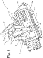
- FIGs 1-6 designated as a whole by 1 is the dispensing assembly of a machine according to one embodiment of the invention, which in this case extends as a whole according to a horizontal axis, designated by A in Figures 4 and 5 .
- the assembly 1 has a supporting structure, which in the figures is exemplified in the form of a casing 2 having an approximately cylindrical shape. Located within the casing 2 are a first part and a second part of an infusion chamber, at least one of which is movable with respect to the other.
- the first part includes a capsule-holder 3, designed to house at least partially a capsule and to deliver the liquid product obtained therefrom.
- the capsule-holder 3 which substantially shares the axis A, comprises a body 4 that is mounted movable with respect to the casing 2 and defines a housing 4a that is able to receive part of a capsule.
- the second part of the infusion chamber comprises an injector device, referred to hereinafter for simplicity as "injector", designated by 5, designed to introduce into a capsule water and/or steam under pressure, supplied through a suitable duct.
- the injector 5 substantially shares the axis A and preferably, but not necessarily, is mounted in a stationary position with respect to the casing 2.
- the injector 5 may be movable in order to obtain an approach between the injector itself and the capsule-holder 5. It is to be noted that, in possible variant embodiments (not illustrated), the function of injection of the fluid into the capsule can be obtained in the first part 3 of the infusion chamber, and the function of delivery of the liquid product can be obtained in the second part 5 of the infusion chamber.
- the guide 7 is stationary, rises from the upper part of the casing 2 and has at least a respective substantially tubular portion that extends axially, thereby defining a passage 8 for introduction and guiding of the capsules.
- the cross section of the guide 7 has a profile substantially corresponding to the cross section of the capsules so as to enable guided introduction thereof with relative precision into the assembly 1.
- the guide 7 defines two guide cavities 7a, which are vertical and opposed to one another and between which the flange of a capsule 30 can be received.
- the body of the guide 7 has at least one discontinuity 7b, where an optical sensor device 9 is positioned, belonging to the control system of the machine according to the invention.
- the optical sensor 9 is preferably a video camera or a photographic camera, designed for acquisition of an image of at least one portion of one of the end faces of the body of a capsule, in particular the face 34 including a sealing foil, as may be seen in Figure 1 .
- the discontinuity 7b is an opening present in the side of the guide 7 facing the optical sensor 9, this opening having dimensions such that a substantial part of the aforesaid sealing foil 34 of the capsule 30 is exposed to an active image-acquisition part 9a of the optical sensor 9.
- the opening 7b has a generally circular profile, through which the most part of the sealing foil of the capsule is exposed to the optical sensor 9, but this is not strictly necessary, since acquisition of a central area of the aforesaid foil is also sufficient.
- the discontinuity 7b may be constituted, instead of by an opening, by a transparent stretch of the wall of the guide 7 that faces the optical sensor 9, in which case the aforesaid transparent part may possibly be configured for performing functions of lens.
- the entire body of the guide 7 may be made of a transparent plastic material.
- the guide 7, instead of having a structure at least in part tubular may include two generally parallel upright elements, each of which defines a respective guide cavity 7a. In this case, the discontinuity that enables exposure of the sealing foil 34 of the capsule to the optical sensor 9 is represented by the free space between the aforesaid two upright elements.
- the optical sensor 9 is preferentially supported by a corresponding support 10 that rises from the upper part of the casing 2, generally parallel to the guide 7.
- the sensor is mounted laterally with respect to the guide 7, preferably on the outside of the casing 2 of the assembly 1.
- a displaceable element is provided, here represented by a hatch 11, hinged for turning according to a substantially horizontal axis, preferably a normally closed monostable hatch.
- the assembly 1 is practically completely housed within a casing (not represented) of the machine for preparing beverages, with the upper mouth of the guide 7 that projects at least slightly on the outside of the casing, or that is substantially flush with an opening of the casing of the machine.
- the hatch 11 may thus be hinged to the body of the guide 7, as in the case exemplified, or else on the outside of the casing of the machine, at the upper inlet of the guide 7.
- the hatch 11 is mounted movable between an open position and a closed position, in which access to the mouth of the guide 7 is prevented or allowed, respectively; in the figures, for simplicity, the hatch 11 is represented in an intermediate position.
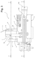
- an electrical control means such as a switch, designated by 12 in Figures 3 and 4 , preferably a micro-switch.
- the switch 12 can be switched between two different conditions, one of which corresponding to an open position of the hatch 11 such as to enable introduction of a capsule 30 into the guide 7.
- the switch 12 may be of a normally open type, which is able to switch into the position of closing of an electrical circuit when the hatch 11 reaches the aforesaid open position.
- the function of the switch 12 associated to the hatch 11 is to start off or enable, via the control system of the machine, a step of acquisition by the optical sensor 9 of an image associated to the body of a capsule 30 that is introduced into the assembly 1.
- the control system of the machine comprises a second sensor device 13, configured for detecting the presence of a capsule 30 after it has been introduced into the guide 7.
- the presence sensor 13 is mounted laterally with respect to the guide 7, preferably but not necessarily on a support 13a, on the side of the guide 7 opposite to the one that the optical sensor 9 faces.
- the sensor 13 may be of any type designed to detect the presence of a capsule in an intermediate position of the path of displacement of the capsule towards its loading position, described hereinafter, and in any case in a position such that the presence of a capsule can be detected before the latter passes beyond the area of image acquisition by the sensor 9, here identified by the opening 7b of the guide 7.
- the active part of the sensor 13 faces a corresponding discontinuity 7c of the guide 7, such as an opening or a transparent part or just a free space.
- the function of the presence sensor 13 is to activate a step of detection by the sensor 9.
- preferentially activation of the sensor 9 depends upon a detection made by the sensor 13, activation of which in turn depends upon the condition of switching of the switch 12.
- the presence sensor 13 may itself be a micro-switch, with a corresponding feeler that drives closing of the circuit when it comes into contact with the body of a capsule.
- the sensor 13 is a sensor that does not come into physical contact with the capsule, for example a proximity sensor or a sensor including an emitter and a receiver of electromagnetic radiation, such as an emitter diode and a phototransistor, possibly integrated in one and the same opto-electronic component available on the market: in the latter case, very schematically, via the emitter electromagnetic radiation is emitted with a predefined wavelength or with a predefined range of wavelengths, for example infrared radiation, the beam impinging on the outer surface of the bottom wall of the capsule at a certain angle, and being then reflected at least in part onto the receiver, thereby enabling determination of the presence of the capsule; in the case of absence of the capsule, the radiation is not instead reflected onto the receiver.
- the sensor 13 may include a photoelectric-cell system, with the emitter and the receiver set in opposite positions on the passage 8 defined by the guide 7 so that a beam of radiation from the emitter to the receiver is interrupted when a capsule is set between them.
- the presence sensor may be positioned also to interact with a peripheral wall of the capsule, instead of with an end wall thereof. It will also be appreciated that, in principle, there is nothing to rule out positioning the sensor 13 on the same side of the guide 7 as where the sensor 9 is located.
- the loading arrangement of the machine includes means for retention of a capsule after it has been inserted into the guide 7.
- a retaining device is provided prearranged so as to define both an intermediate position of retention of a capsule, in which the capsule itself is kept in a static condition and exposes at least a part of its own sealing foil 34 to the optical sensor 9, and the aforementioned loading position, in which the capsule is substantially coaxial to at least one of the capsule-holder 3 and the injector 5.
- the retaining device comprises two opposed elements, here defined as “jaws”, designated by 14.
- the jaws 14 are set substantially symmetrically on opposite sides of the axis A, in one and the same transverse plane and are mounted so that they can oscillate according to respective axes generally transverse to the direction of displacement of the capsule along the guide 7.
- each jaw 14 has a respective vertical groove 14a (see Figure 1 ) that extends at least in part underneath a corresponding cavity 7a of the guide 7, as far as within the assembly 1, in an intermediate position between the injector and the capsule holder (see Figure 4 ).
- the jaws 14 hence extend in length substantially perpendicular to the axis A and are articulated via at least one pin 14b, here substantially parallel to the axis A, coupled to the casing 2.
- the jaws 14 may be provided with springs or similar elastic means 14c (partially visible in Figures 6 , 15 , and 17 ), provided for pushing the jaws themselves towards a position of equilibrium or where they are set close together.
- the aforesaid position is obtained without the aid of dedicated springs, and the intrinsic elasticity of the material constituting the jaws 14 - for example, a plastic material - is exploited to enable divarication thereof, without rotation pins.
- the jaws 14 are articulated in a generally lower region thereof, but obviously the point of articulation may be different.
- the jaws 14 are configured for defining two different positions of retention, and precisely an intermediate position of retention and a final position of retention, downstream of the previous one, corresponding to the loading position of the capsule.
- Figure 7 illustrates, via a merely schematic cross section, a possible embodiment of the opposed jaws 14, with the simultaneous artificial presence of two capsules 30 between them
- Figures 8 and 9 illustrate a jaw 14 in front elevation and in perspective view, respectively
- Figure 10 illustrates in perspective view a portion of the assembly 1 of Figure 1 , in the absence of a capsule in the guide 7.
- first retaining means or elements 15 for example formed by projections of the body of a jaw 14 towards the inside of the corresponding groove 14a.
- the upper part of the jaws 14 extends on the outside of the guide 7, and the retaining elements 15 are located at respective interruptions of the cavities 7a of the insertion guide 7.
- the retaining elements 15 are in relative positions such that, when the jaws 14 are in the position of equilibrium where they are set close to one another, they arrest the movement by gravity of the capsule 30 along the cavities 7a and the grooves 14a, i.e., they constitute a hindrance to sliding of the flange of the capsule, as represented schematically in the case of the capsule 30 shown in the top position in Figure 7 .
- the retaining elements 15 move away and thereby enable prosecution of the movement of the capsule 30 downwards, by gravity, along the cavities 7a and then along the grooves 14a.
- the release of the capsule from the first retaining elements 15 is obtained following upon application on the capsule of a force of thrust in its direction of movement, for example a manual thrust, such as to cause divarication of the jaws 14 that brings the elements 15 out of interference with the peripheral profile of the flange of the capsule.
- two second retaining means or elements 16 here formed by generally converging lower portions of the two jaws 14 or in any case shaped in such a way that the lower ends of the grooves 14a are closer to one another than are the retaining elements 15, when these are in the corresponding position of release.
- the jaws 14 divaricate, but the presence of the second elements 16 in any case arrests the downward travel of the capsule 30 that has in the meantime been freed from the first elements 15, even in the case where the jaws 14 had not yet returned elastically to the position of equilibrium.
- This second retaining condition is highlighted by the capsule 30 represented in the bottom position in Figure 7 .
- the position defined by the second retaining elements 16 corresponds, in one embodiment, to the loading position of the capsule, in which it is axially aligned to the capsule-holder 3.
- each jaw 14 is shaped - in particular in a part thereof internal to the casing 2 - so as to interact or interfere with parts or elements of the capsule-holder 3 in order to bring about divarication of the jaws themselves in the course of the relative movement between the injector 5 and the capsule-holder 3, in such a way that the capsule is released from the second retaining elements 16 here represented by the lower portions of the jaws 14.
- the body of the jaws 14 may be provided with corresponding lead-ins or inclined planes, or present projections designed to co-operate with corresponding parts present on the capsule-holder, such as lead-ins or inclined planes.
- lead-ins are designated by 14d.
- the first retaining elements and the second retaining elements do not necessarily have to be integrated in one and the same device including two jaws and could hence also have a conformation different from the one exemplified here, albeit preserving the general function of identifying two positions of retention of a capsule, one downstream of the other, during its displacement in the direction and according to the orientation determined by the guide 7.
- the first retaining elements can themselves include two opposed jaws, above two other jaws that form the second retaining elements; or again, the first retaining elements may comprise one or more elastic tabs or elements set in a retractile way along the guide 7, with the second retaining means constituted by underlying jaws.
- the position of retention defined by the second retaining means 16, i.e., the position of loading of the capsule, does not necessarily mean that the capsule shares the axis A.
- the axis of a capsule could also be parallel or slightly inclined with respect to the axis A: in such an embodiment the conicity of the peripheral wall of the capsule and of the housing defined by the capsule-holder can be exploited to obtain a relative movement of centring between the elements in question, during advance of the capsule-holder, as clarified hereinafter.
- a linear guide defined on each of the two opposite sides of the casing 2 is a linear guide, designated by 17.
- respective lateral guide elements visible for example in Figure 6 , where they are designated by 3a) of the capsule-holder 3 are engaged.
- the capsule-holder 3 then has parts or elements configured to bring about divarication of the jaws 14 as it advances towards the injector 5, these parts possibly comprising, for example, front elements and/or a leading edge of the capsule-holder 3 which define an inclined plane, designed to interact with corresponding lead-ins or inclined planes defined on each jaw 14, such as the lead-ins 14d of Figures 8-9 .
- the cup-shaped body 4 of the capsule-holder 3 defines the corresponding housing 4a.
- the body 4 has a side or peripheral wall, which defines an inner surface of the housing 4a that is substantially frustoconical, or has some other shape congruent with that of the side wall of the capsules used.
- the body 4 has a bottom wall with a corresponding passage (not indicated), which sets the inside of the housing 4a in fluid communication with a duct 18 for delivery of the liquid product that can be obtained using the capsule.
- a perforating device 19 comprising one or more tips or reliefs.
- the arrangement is such that the liquid that flows out of the capsule, which is torn at the bottom by the aforesaid tips, can reach the delivery duct 18.
- the latter may be connected, for example via a flexible tube or a rigid coupling with a number of mating profiles, to a nozzle for delivery of the liquid product.
- the invention may be applied also to the case of dispensing assemblies for capsules that have a pre-perforated bottom wall, in which case it is not necessary to provide a perforating device inside the capsule-holder.
- the assembly comprises ejector means, designed to push a capsule towards the outside of the housing 4a according to a relative displacement between the injector 5 and the capsule-holder 3 from the close position to the spaced-apart position.
- ejector means preferably comprise a longitudinally extended ejector member, which is movable with respect to the capsule-holder 3.
- the bottom wall of the capsule-holder 4 is traversed by a passage which substantially shares the axis A, in which the ejector member is slidably mounted.
- the ejector member is configured as rod or stem 20, having a cross section preferably at least in part cylindrical.
- the stem 20 also passes through a central passage of the supporting wall of the perforating device 19 inside the capsule-holder, when such a perforating device is provided.
- operatively set between the capsule-holder 3 and the stem 20 is a spring, for forcing the stem itself towards a retracted position within the chamber.
- the stem 20 has a longitudinal cavity, represented for example in Figure 14 , in which a guide projection 4b of the body 4 of the capsule-holder is located, and set between the aforesaid projection 4b and a contrast element 20a at the distal end of the aforesaid longitudinal cavity is the above spring, designated by 20b.
- the housing 4a In its mouth part, the housing 4a is limited by a leading annular edge, and the capsule-holder 3 has coupling members 21, which project at the front beyond the aforesaid leading edge.
- three coupling members 21 are provided, set at approximately 120° apart, at least one of which is preferably positioned in the lower area of the capsule-holder 4, as may be seen, for example, in Figure 4 .
- the members 21 form part of a system aimed at facilitating separation of a capsule from the injector 5, in a step of discharge of the spent capsule in the cycle of use of the assembly 1.
- the members 21 may be pivoted to the body 4 of the capsule-holder 3 and forced elastically into a position of closing towards the axis A, for example by means of a spring or other accumulator of mechanical energy.
- the aforesaid closing position is obtained without the aid of dedicated means, and the intrinsic elasticity of the material constituting the members 21 - for example, a plastic material - is exploited to enable divarication thereof.
- the members 21 may be formed integral with the body 4 and/or provided so that the position of closing thereof is obtained in the absence of elastic loading: in such a case, the presence of possible elastic means and/or the intrinsic elasticity of the constitutive material is exploited for enabling opening or divarication of the members 21 and subsequent return thereof to the closed position.
- the coupling members 21 have, in the respective front region, a respective tooth, where the aforesaid front region projects at the front beyond the leading edge of the capsule-holder 3.
- the machine has an actuation system 22, which can be operated to bring about relative movements of the injector and the capsule-holder between a spaced-apart position, in which the capsule can reach its loading position, and a close position, in which the injector and the capsule-holder define between them the infusion chamber, for enabling injection of the fluid into the capsule.
- the spaced-apart position is visible in Figures 4 and 6
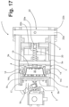
- the close position is visible in Figures 16 and 17 .
- the actuation system 22 comprises a substantially toggle or connecting-rod/rocker mechanism, which may for example be governed manually by a user via a lever.
- the actuation mechanism may include gears.
- the aforesaid mechanism preferably includes a shaft 22a that extends between the two opposite sides of the casing 2 and that is able to turn about an axis substantially perpendicular to the direction of displacement of the capsule-holder 3, here substantially coinciding with the axis A.
- the casing 2 defines for this purpose passages - with possibly associated bearing members or the like - for the end regions of the shaft 22a, which project outside the casing itself, as may be seen, for example, in Figure 1 ; to these projecting ends of the shaft 22a there may be constrained a lever 22b, represented only partially, for manual actuation.
- the mechanism may then comprise a system of rockers and connecting rods according to known technique.
- the actuation system 22 is designed to cause relative movements of the injector 5 and the capsule-holder 3 between the aforesaid spaced-apart position and the aforesaid close position, in a direction of displacement that is generally transverse to the direction of movement of a capsule determined by the insertion guide 7.
- the actuation system 22 is driven to cause - for example, with the lever 22b - a counter-clockwise rotation of the shaft 22a.
- This rotation can be obtained also in an assisted way, for example by equipping the assembly with a controllable electric actuator, in which case the lever 22b is not indispensable.
- This rotation brings about actuation of the mechanism such as to cause a thrust forward of the capsule-holder 3 towards the injector 5.
- the capsule-holder 3 is constrained to perform the linear movement in opposite direction, thanks to the engagement of the elements 3a in the opposed guides 17: in this way, it is possible to determine approach of the capsule-holder 3 to the injector 5.
- a rotation in a clockwise direction of the shaft 22a it is possible to obtain a reverse displacement, i.e., a recession of the capsule-holder 3 away from the injector 5.
- a leading end of the stem 20 is provided with a sealing ring (not indicated), whilst the rear end of the stem 20 has a generally rounded configuration in order to co-operate with a cam member 23 that is fixed with respect to the shaft 22a in rotation.
- the rear end of the stem 20 provides a cam-follower that co-operates with a cam surface defined by the member 23.
- the stem may also be constrained in a substantially stationary position at its rear end.
- the cam/cam-follower coupling referred to above is configured in such a way that, in the passage from the position where the injector 5 and the capsule-holder 3 are set at a distance apart to the position where they are set close up to one another, the stem 20 assumes a position with respect to the bottom of the capsule-holder 3 such as not to interfere with insertion of a capsule 30 in the housing 4a, whereas in the passage from the position where the injector 5 and the capsule-holder 3 are set close up to one another to the position where they are set at a distance apart, the stem 20 assumes a position with respect to the bottom of the capsule-holder 3 such as to cause expulsion of the capsule 30 from the housing 4a.
- a capsule 30 (also known as "cartridge”) that can be used in a machine according to the present invention, as already exemplified above.
- This capsule 30 has a structure that is basically known, which is here described merely to enable easier understanding of an embodiment of the present invention.
- the capsule 30 contains a dose 31 of at least one substance that is able to form a liquid product via water and/or steam.
- the dose 31 may be constituted by ground coffee, or by another precursor of a liquid product, such as for example a beverage, tea, powdered or granular chocolate, products for preparing broth, soups, drinks and infusions of various nature: the above list is to be understood as being provided purely by way of non-imperative example, and in the framework of the invention also capsules containing soluble substances are to be understood as being included.
- the preparation of coffee with the dose 30 that is hence understood as being constituted by ground coffee.
- the wall or foil 34 is connected in a fluid-tight way, for example by heat sealing, to the side wall 32a of the body 32 of the capsule, in particular to an outer flange thereof 32c which surrounds the mouth part of the body 32 and that extends towards the outside in a direction transverse with respect to a central axis of the body 21.
- the body 32 has a cup-like conformation or is shaped like a tray diverging from the bottom wall 32b towards the end closed by the foil that forms the wall 34.
- this diverging conformation is a frustoconical conformation, which is not on the other hand imperative, in so far as the capsule 30 may present as a whole different shapes, for example a cylindrical, prismatic, frustopyramidal shape, or the like.
- the bottom wall 32b may be variously shaped; for example, it may be plane, concave, or convex.
- Associated to one of the end walls 32b and 34 of the body 32 is graphic information representing the type of capsule, for example the type of liquid product, e.g., strong coffee, or weak coffee, or Americano, or cappuccino, or tea, etc.
- the above information is present on the foil 34.
- the aforesaid information may be encoded by a graphic code that is inscribed in a circular area concentric to the centre of the respective wall of the capsule body - here the wall or foil 34 - and is configured for being read by the optical sensor 9 of a machine according to the invention.
- a graphic code may be of any conception known in the sector, for example a two-dimensional barcode, such as a QR code or a barcode with concentric rings.
- the encoded data may include the type of liquid product associated to the capsule and information representing its optimal modalities of preparation, such as the temperature of the water to be injected or that of the product to be dispensed, the pressure of the water, the amount of water, particular cycles of operation of the pump of the machine, such as for example the presence or absence of a pre-infusion step (i.e., a step of activation of the pump for a predetermined time, such as to enable injection of a first amount of liquid into the capsule, which is followed by a pause in injection of liquid and a new activation of the pump, to obtain effective delivery of the liquid product).
- encoded in the control system is at least one program that uses the information and/or parameters acquired each time from the graphic code appearing on a capsule for controlling operation of the machine accordingly.
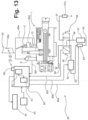
- Represented schematically in Figure 13 is a machine for preparing liquid products according to one embodiment of the invention, designated as a whole by 50.
- the machine 50 comprises a tank 51 for cold water, with an outlet duct 52 on which a pump 53, of a type in itself known, for example an electromagnetic pump, is operative. Via the duct 52 the tank 51 is connected to an inlet of a boiler 54, which is also of a type in itself known. An outlet of the boiler 54 is connected to a duct 55 for supplying hot water and/or steam under pressure to an inlet of a distributor device, for example a slide distributor, designated by 56.
- a distributor device for example a slide distributor, designated by 56.
- the distributor 56 When the distributor 56 is in a first operating position (on the left in Figure 13 ) it sets the duct 55 in communication with a duct 57 that supplies the nozzle 57a of an external arm for delivery of hot water and/or steam; when, instead, the distributor 56 is in a second operating position (to the right in Figure 13 ), the duct 55 is set in fluid communication with a duct 58 for supplying hot water under pressure to the dispensing assembly 1 and especially to its injector 5. Finally, when the distributor 56 is set in an inoperative position (at the centre, as illustrated in Figure 13 ), the duct 55 is in fluid communication with a duct 59 for return of water to the tank 51.
- the scheme of Figure 13 is merely an example, with the distributor 56 that may be motor-driven or replaced by suitable connectors and electrical valve means governed by the control system of the machine 50, for example in the case of machines that are not provided with the nozzle 57a.
- the distributor 56 In the case of a manually operated distributor, preferentially associated thereto are electrical sensor means (for example, one or more microswitches) for detecting the position assumed by the distributor.
- electrical sensor means for example, one or more microswitches
- Figure 13 represents, once again schematically, the control system of the machine, including a control unit 60 comprising processing means, such as for example a microcontroller 61, and non-volatile memory means 62, in which instructions for operation of the machine are encoded, for example in the form of one or more operating programs.
- processing means such as for example a microcontroller 61
- non-volatile memory means 62 in which instructions for operation of the machine are encoded, for example in the form of one or more operating programs.
- the control unit 60 and especially the microcontroller 61, is provided for controlling the heating means of the machine, here represented by an electrical resistance of the boiler 54, as well as the means for supply of the fluid to be injected into a capsule, here represented by the pump 53, to obtain a plurality of possible operating modes of the machine on the basis of the aforesaid encoded instructions contained in the memory means 62 and on the basis of information acquired from a capsule 30 by way of the sensor 9.
- the dashed arrows 60a and 60b exemplify the control lines from the unit 60 to the pump 53 and to the boiler 54, respectively.
- the pump and the boiler may also be configured for issuing a feedback signal to the unit, for example via a pressure and/or flow-rate sensor and a temperature sensor, respectively.
- the dashed arrow 60c exemplifies the control line between the sensor means associated to the distributor 56 and the unit 60 so that the latter knows the operating position imparted manually on the distributor (as has been said, in the case of completely automatic operation, it may be the unit 60 that governs positioning of such a distributor or the operating condition of valve means that are provided in place of it).
- the arrow 60d exemplifies the control line between the switch 12 and the presence sensor 13, whereas the arrow 60e exemplifies the control line between the presence sensor 13 and the optical sensor 9. Finally, the arrow 60f exemplifies the line of communication between the optical sensor 9 and the unit 60.
- the scheme provided herein has the sole purpose of highlighting in an intuitive way the functional connection between the various parts of interest, since the circuit arrangement may be variously configured, the functions thereof remaining the same.
- the switch 12, the sensor 13, and the sensor 9 could all come under the unit 60, i.e., with the switch 12 that communicates the open condition of the hatch 11 to the unit 60, and the latter that accordingly verifies the state of the sensor 13 and, in the case of detection of a capsule, activates the sensor 9 for the time necessary for image acquisition.
- opening of the hatch 11 causes closing of the switch 12 (which is normally open), thereby enabling supply of the sensor 13.
- the latter which is for example an opto-electronic component of the type referred to previously, also functions as switch (which is normally open, in the absence of a capsule) and is set in the supply circuit of the sensor 9: detection of a capsule thus enables supply of the sensor 9 for the acquisition time deemed necessary in the design stage.
- the injector 5 has a respective main body 5a, stationary with respect to the casing 2, and here provided with a perforating device, which may be of any known conception.
- the body 5a has a cavity that houses at least in part the aforesaid perforating device, designated by 5b.
- This device 5b basically comprises one or more tips - preferably an array of tips - facing the capsule-holder 3 and substantially parallel to the axis A.
- the tips may have a structure provided with at least an axial opening or an axial groove in order to enable supply of the fluid under pressure within a capsule 30, after perforation of its foil 34.
- the arrangement is such that the fluid under pressure that is supplied by means of the duct 58 to the injector 5 can penetrate into the capsule 30 after perforation of its foil 34.
- the cavity of the body 5a is closed at the front by a closing member 5c, which shares the axis A, and is defined hereinafter for simplicity as "plate”.
- the plate 5c is provided with holes aligned or substantially coaxial to the tips of the device 5b, and is able to slide towards the inside of the cavity of the body 5a, countering the elastic reaction of a spring (not indicated).
- the plate 5c may have a substantially disk-shaped body, in particular having the shape of a lobed disk, with a front wall provided with the holes for the aforesaid tips, and rear appendages provided with end teeth engaged in corresponding linear guides defined in the peripheral wall of the body 5a.
- the outer face of the front wall of the plate 5c is preferentially provided with a gasket, which is also provided with holes for the tips of the perforating device 5b.
- the plate is preferentially provided at the rear with an annular gasket, designed to constitute a seal with respect to the body 5a.
- the body of the plate 5c is shaped for defining passages or recesses, one of which is designated by 5d in Figure 4 , in axial positions corresponding to those of the coupling members 21 of the capsule-holder 3.
- the corresponding front gasket is preferably provided with corresponding slits or windows.
- the aforementioned rear appendages of the plate 5a in addition to preventing the front of the plate itself from sliding out, are preferentially sized and positioned in such a way that the front surface of the plate 5c (or its gasket) is held by a corresponding spring in an advanced position.
- the dimensions of the plate 5c with the corresponding appendages, of the body 5a with the corresponding cavities and guides, as well as of the tips of the perforating device 5b, are such that, when at rest, the plate 5c is held by the corresponding spring in the aforesaid advanced position (visible, for example, in Figure 4 ), where each tip engages or is substantially coaxial to a respective hole of the front wall of the plate itself and of the corresponding gasket, but without substantially coming out thereof.
- the thrust on the plate 5c exerted by means of a capsule 30 causes the perforating device 5b to assume an operative or extracted condition, where its tips project from the holes of the plate 5c, following upon recession of the latter towards the inside of the cavity of the body 5a, countering the elastic reaction of the corresponding spring.
- the injector 50 may be provided with a perforating device of some other type, and not necessarily provided with tips, there possibly being sufficient also reliefs designed to bring about tearing of the wall or foil 34 of the capsule 30.
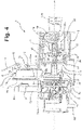
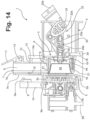
- Figures 4 and 6 illustrate, in various cross sections, the assembly 1 with the capsule-holder 3 in a retracted position
- Figures 14-15 are cross sections similar to those of Figures 4 and 6 , but with the capsule-holder 3 advancing
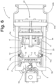
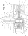
- Figures 16-17 are similar to Figures 4 and 6 and 14-15 , respectively, but with the capsule-holder 3 and the injector in the position for carrying out infusion where they are set close up to one another
- Figure 18 is similar to Figures 4 , 14 and 16 , with the capsule-holder 3 at the end of a travel of recession thereof (i.e., in a condition substantially corresponding to that of Figure 4 ).
- the assembly 1 has a loading arrangement, aimed at enabling guided insertion, from above, of a capsule 30, in a direction that is generally transverse to the direction of relative displacement of the two parts 3, 5 of the infusion chamber.
- the aforesaid loading arrangement includes the upper entry passage 6, which opens substantially in an intermediate area between the capsule-holder 3 and the injector 5.
- the passage 6 and the guide 7 are shaped and have dimensions such as to enable introduction of a capsule 30 in a substantially vertical loading direction, here transverse to the axis A, with an orientation such that the foil 34 of the capsule 30 faces the injector 5, i.e., the sensor 9.
- the casing 2 On the opposite side with respect to the guide 7 the casing 2 has a lower exit passage 2a, for unloading the spent capsule 30 from the assembly 1.
- the passage 6 and the guide 7 are shaped and have dimensions such as to guide with relative precision a capsule 30 towards two retaining areas, which are set downstream of one another, here identified by the jaws 14; the exit passage 2a preferably has dimensions larger than the entry passage in order to enable the capsule 30 to drop freely by gravity out of the casing 2.
- the capsule-holder 3 In the loading step, with the actuation system 22 in the initial position ( Figures 4 and 6 ), the capsule-holder 3 is in the respective retracted loading position, i.e., set at a distance from the injector 5.
- a capsule 30 can be introduced into the guide 7.
- the capsule 30 is inserted into the guide with its flange 32c set generally vertical that engages the opposed cavities 7a of the guide 7.
- the capsule proceeds by gravity until it encounters the first retaining means 15 ( Figures 7-10 ) defined by the opposed jaws 14, which arrest the movement thereof in the direction established by the guide 7; in the case exemplified, in the position of retention determined by the elements 15, the capsule 30 is in any case still within the guide 7 (see also Figure 1 ).
- Switching of the switch 12 caused by opening of the hatch 11 activates the sensor 13, which detects the presence of the capsule 30 in the intermediate position of retention ( Figure 4 ), thereby enabling the step of acquisition of the graphic code present on the foil 34 via the optical sensor 9.
- the control unit 60 acquires information regarding the type of capsule introduced and/or the optimal parameters of preparation of the liquid product, which here are assumed as being the temperature of the water to be injected and at least one of the pressure and the amount of water to be injected.
- the unit 60 controls the boiler 54 to obtain the aforesaid optimal temperature for the infusion water.
- a thrust must be applied to the capsule 30 in the direction of movement determined by the guide 7 in order to switch the first retaining elements 15 from the respective intermediate retention condition to a respective condition of release.
- the thrust exerted on the capsule 30 determines a slight divarication of the jaws 14, such as to free the capsule 30 from the elements 15 and enable prosecution of its displacement by gravity as far as the loading position, determined by the second retaining elements 16 ( Figures 7-9 ).
- the thrust may be imparted on the capsule 30 manually, for example using a finger, or else, more conveniently, the hatch 11 may have a lower appendage designed to project within the passage 8 of the guide 7 in such a way that - upon closing of the hatch 11 - the aforesaid appendage exerts on the capsule the thrust downwards necessary to cause release thereof from the retaining elements 15.
- the capsule 30 In its loading position, the capsule 30 is kept by the second retaining elements 16 of the jaws 14 substantially coaxial to the capsule-holder 3 and to the injector 5, between these two parts of the infusion chamber that are still in the spaced-apart position (see, as regards the position of the capsule, Figures 14-15 ).
- the foil 34 of the capsule faces the front surface of the plate 5c of the injector 5, i.e., its front gasket, at a short distance therefrom.
- the front edge of the capsule-holder 3 comes into contact with the flange of the capsule 30 so as to push it forcedly against the plate 5c of the injector 5, with the capsule 30 that cannot penetrate further into the housing defined by the body of the capsule-holder, as may be seen precisely in Figures 16 and 17 .
- the front teeth of the engagement members 21 penetrate into the recesses 5d of the plate 5c, as far as the final end-of-travel position of the capsule-holder 3, visible in Figure 16 , where the front of the capsule 30 is set up against the front gasket of the plate 5c, by means of the front edge of the capsule-holder 3.
- the peripheral region of the bottom wall of the capsule 30 bears upon a peripheral region of the wall of the perforating device 19 not provided with tips (for example, in the case of the bottom wall with concavity as represented in Figure 12 ) so that the bottom of the capsule is not initially perforated.
- the bottom wall of the capsule has been set up against the tips of the perforating device 19 without this determining a substantial perforation or tearing of the bottom, or again that the bottom comes to occupy a position at a short distance from the aforesaid tips: this can be obtained by appropriately sizing the housing 4a, and in particular the height of its front edge bearing upon which is the flange of the capsule 30.
- the bottom of the former has already been perforated by the tips of the perforating device 19. As has been said, moreover, in the case of an assembly 30 for pre-perforated capsules, it is not necessary to provide the perforating device 19.
- the capsule 30 is unable to penetrate any further into the capsule-holder 3.
- the capsule-holder 3 continues in any case to advance, and this brings about yielding of the spring inside the injector 5, and thus recession of the plate 5c that is bearing upon the foil of the capsule 30.
- the above recession, and the simultaneous advance of the capsule-holder 3 has, as consequence, that the tips of the perforating device 5b of the injector 5 exit from the corresponding holes of the plate 5c and perforate the foil of the capsule, as far as the position of maximum advance of the capsule-holder 3, visible in Figures 16-17 .
- the rear end of the stem 20 is pushed by the corresponding spring 20b against the cam surface defined by the member 23, fixed in rotation with respect to the shaft 22a.
- This cam surface is parameterized in such a way that, in any case, corresponding to advance of the capsule-holder 3 is a progressive recession of the leading end of the stem 20 within the housing 4a.
- the position of maximum recession of the stem 20 is precisely visible in Figures 16-17 .
- the sealing ring at the leading end of the stem 20 co-operates with the bottom wall of the body 4 in order to prevent passage of liquid towards the inside of the passage in which the stem 20 slides.
- the hot water under pressure is thus forced into the capsule 30, by means of the tips of the perforating device 5b of the injector 5, to obtain the infusion with the ground product (for example, coffee) contained in the capsule 30.
- the front gasket of the plate 5c improves the fluid tightness in regard to the sealing foil of the capsule 30, during introduction into the latter of water under pressure.
- the liquid product generated by the infusion can flow out through the duct 18.
- the pressure that is set up within the capsule 30 causes its bottom to start to undergo deformation and be pushed against the tips or reliefs of the perforating device 19, until perforation or tearing is obtained, which enables outflow of the liquid product towards the duct 18.
- the perforating devices 19 and 5b may not be present, in the case of pre-perforated capsules.
- the unit 60 then deactivates the pump 53, when the amount and/or pressure of the fluid delivered correspond to those deduced on the basis of the graphic code associated to the capsule 30.
- the actuation system 22 can be driven in a direction opposite to the previous one to bring the capsule-holder 3 back into the initial position of Figures 4 and 6 .
- recession of the capsule-holder 3 there is obtained a sliding of its body 4 with respect to the jaws 14 opposite to the one described previously and a recession of the coupling members 21.
- the front teeth of the coupling members 21 come back into contact with the front part of the flange of the capsule 30 (i.e., its part covered by the foil 34).
- the jaws 14 are in any case still kept in a divaricated condition by the body of the capsule-holder 3, i.e., by the corresponding elements responsible for this: in this way, the flange of the spent capsule cannot be withheld by the jaws 14.
- the arrangement is such that - when, upon ceasing of the action of divarication operated by the body 4, the jaws 14 re-close - the jaws themselves have already been overtaken in the movement of recession by the flange of the capsule 30.
- the rear end of the stem 20 is kept by the corresponding spring 20b in contact with the cam surface defined by the member 23, with a sliding opposite to the previous one: in this way, in the prosecution of the recession, the leading end of the stem 20 presses on the bottom of the capsule 30, pushing it out of the housing 4a, thereby bringing about also extraction of the tips of the perforating device 19 from the bottom of the spent capsule, when the aforesaid perforating device is present.
- the thrust exerted in this way by the stem 20 on the bottom of the capsule 30 is such as to overcome in any case also any possible mechanical interference between the body of the capsule and the internal surface of the housing 4a.
- the machine according to the invention preferably has a control system that includes processing means 61, non-volatile-memory means 62, and an optical sensor device 9 designed for acquisition of an image of at least one portion of at least one of the end walls of the body of the capsule 30, here the wall represented by the sealing foil 34, associated to which is graphic information representing the type of capsule, and the processing means 61 are provided for controlling at least the heating means 54 and the supply means 53 to obtain a plurality of possible operating modes of the machine on the basis of encoded instructions contained in the memory means 62 and on the basis of information acquired from the capsule.
- processing means 61 are provided for controlling at least the heating means 54 and the supply means 53 to obtain a plurality of possible operating modes of the machine on the basis of encoded instructions contained in the memory means 62 and on the basis of information acquired from the capsule.
- the brewing information may include values of preparation parameters (for example, a value of temperature of the liquid) and/or information representing preparation parameters: with reference to this latter case, considering for example a volume or a pressure of liquid to be injected into the capsule, the corresponding brewing information may include - instead of the value of the aforesaid volume or pressure - information of control of the pump aimed at obtaining that given volume or that given pressure, such as for example the time of activation of the pump or the number of pulses of the pump necessary to obtain that given volume or pressure.
- the encoded instructions contained in the non-volatile-memory means 62 already comprise these sets of brewing information, which are differentiated according to the type of capsule 30.
- sets of brewing information - which each include information on the temperature and information on at least one of the pressure and the amount of fluid to be injected - are not read each time from the capsule inserted into the machine, but are pre-stored in its control system.
- the processing means 61 are provided for comparing an image acquired via the optical sensor 9 with a series of reference images, encoded in the memory means 62, and for associating accordingly one of the aforesaid sets of brewing information to a corresponding type of capsule in order to start off in an automatic way an operating mode of the machine from among the plurality of possible operating modes, each distinguished by a set of brewing information of its own.
- the control logic merely has to recognize the type of capsule introduced into machine.
- the type of capsule is recognized by acquiring an image of its sealing foil (but it could also be an image of the bottom wall of the capsule), which is then compared with reference images contained in the memory means.
- a first database encoded in the memory means 62 contains digitalized images of a plurality of different capsules, also capsules of different manufacturers and/or different types of capsule for each manufacturer.
- a second database encoded in the memory means 62 contains a plurality of sets of information on optimal preparation, each of which is associated to the images of a respective encoded capsule, for example the capsule of each manufacturer, or each of the capsules of one manufacturer, if this manufacturer puts different types of capsules on the market.
- the image of a portion of the sealing foil 34 of a capsule acquired via the optical sensor 9 is compared with those contained in the first database, using image-comparison techniques in themselves known.
- the first database contains a plurality of reference images for each type of capsule, in each of which a substantial portion of the sealing foil of that capsule has a different angular position: in this way, recognition of the capsule is totally independent of the angular position assumed by the foil 34 of a capsule 30 with respect to the sensor 9, after the aforesaid capsule has been inserted into the dispensing assembly 1 through the guide 7.
- the type of recognition proposed can be executed perfectly with relatively low reading resolutions by the optical sensor 9 so that also the reference images may be at low resolution, with consequent contained dimensions in terms of number of bits and hence a relatively modest capacity of the memory means 62.
- the sensor device 9 may be a commercially available video camera or photographic camera of a CCD or CMOS type, with low resolution and very contained cost.
- the solution proposed is based upon recognition of the fact that different capsules, even capsules of various manufacturers, carry on the respective sealing foils different graphic symbols such as to enable easy reading by an optical image-acquisition sensor with a relatively low resolution. Given the differences between the different capsules, the image analysis may even be limited to just a portion of the foil 34, which will be preferentially a central portion, inscribed in a circular area concentric with respect to the foil of the capsule.
- the sealing foils of two types of capsules of a different manufacturer present in any case some elements of differentiation.
- the foil of the capsule "X" of the manufacturer "Y” will carry the name or trademark of the manufacturer and the name or a logo assigned to the specific liquid product associated to the capsule “Y” (for example, ristretto);
- the capsule "Z" of the same manufacturer "Y” will carry, in addition to the same name or trademark, the name or the logo assigned to the different liquid product associated to the capsule "Z” (for example, lungo).
- the graphic information associated to the sealing foil 34 of a capsule 30 may comprise a proprietary graphic sign of the manufacturer of the capsule, such as a distinctive sign, and at least one auxiliary graphic element, identifying the liquid foodstuff product corresponding to that type of capsule of that particular manufacturer.
- the encoded instructions contained in the memory means 62 may comprise a single operating program, which can be modified via the sets of brewing information associated each time to reading of the image of a capsule 30 to obtain the plurality of operating modes of the machine 50.
- this presupposes a greater capacity of the memory means 62 there may be stored a plurality of different operating programs corresponding to different possible operating modes of the machine, where each of these programs is distinguished by the set of brewing information of a corresponding type of capsule.
- the sets of brewing information or the corresponding programs encoded in the memory means comprise at least one predetermined set of information or one predetermined program, to which there corresponds a predetermined operating mode of the machine, for example distinguished by average or safety values of temperature and amount and/or pressure.
- the processing means 61 of the control unit are provided for starting off this predetermined operating mode in the case where the image acquired via the optical sensor device 9 is not congruent with any of the reference images encoded in the nonvolatile-memory means 62.
- the machine 50 is provided with means for updating and/or modifying at least one between the instructions and the reference images encoded in the non-volatile-memory means.
- the machine 50 is provided with a communication device, designated as a whole by 63 in Figure 10 , for example represented by a communication port of the control unit 60.
- a communication port for example, a USB port
- the software of the machine for example the aforesaid databases
- the communication device 63 used for updating the software of the machine 50 may also include a modem or the like, for interconnection of the control system to a communication network (for example, a telephone network or the Internet) for receiving the updating data, or again a wireless transceiver, for example of a Wi-Fi or Bluetooth type.
- the owner of a machine according to the invention can download from a dedicated website the updating software and then carry out the corresponding upload into the control unit 60, with the aid of a suitable utility made available by the manufacturer of the machine.
- the means for updating and/or modifying at least one between the instructions and the reference images encoded in the non-volatile-memory means 62 may include the optical sensor 9 itself.
- the control unit 60 a programming mode, which can be activated via at least one dedicated key or else by pressing - according to a specific combination and/or sequence - one or more control keys provided in any case on the machine for other functions.
- the machine may be provided with a display 64 and a small keypad, which constitutes a communication device. By pressing a key, the programming mode is activated, which is to be followed by introduction into the machine of the capsule of a new type, according to the modalities described previously.
- the unit 60 After introduction of the capsule and acquisition of the corresponding image, the unit 60 sets itself in a step where it waits for preparation parameters regarding that particular capsule, which parameters may be made available by the manufacturer of the capsule, for example through its website or directly on the package of the capsules.
- the sequence of entry of the parameters is determined by the unit 60, by issuing a command for showing on the display 64 the corresponding requests.
- the control unit 60 can itself be provided for generating the necessary series of reference images differentiated from one another in terms of angular positioning, starting from the image acquired via the sensor 9.
- a programming device having a respective body that can be inserted into the dispensing assembly 1 of the machine 50, in particular a body substantially similar to that of a capsule 30.
- "programming capsules” are basically provided, which do not necessarily contain the ingredients of a liquid product, but have the main function of carrying the data for updating the machine 50 for a given type of capsules.
- control system of the machine 50 may include a reader of RFID tags, designated in Figure 10 by 65, and the aforesaid programming capsules - one of which is designated by 30' once again in Figure 10 - include an RFID tag 30a that can be read by the reader 65, in which the program and/or the optimal brewing information of the liquid product referred to in the aforesaid type of capsules are/is encoded.
- the programming capsule 30' then has a respective foil 34 bearing the graphic symbols characteristic of the type of capsules in question.
- start of a programming step for example, by pressing a key or a sequence/combination of keys
- the control system goes into a waiting step.
- the programming capsule 30' is inserted into the assembly 1, and the control unit 60 acquires the image of its foil 34 or of a substantial portion thereof, used to encode the image or the reference images to be stored in the memory means.
- the memory means associated to this image or set of images is the program or the optimal brewing information, which is acquired by the reader 65 directly from the tag 30a associated to the programming capsule 30'.
- the machine 50 is in a condition to operate automatically in an operating mode deemed optimal with different capsules, even with capsules of different manufacturers, including different capsules of one and the same manufacturer, this further favouring the range of choice of the end consumer, who, with complete satisfaction, will be able to use on his own machine capsules of different origin.
- the limits of known machines provided with systems for automatic recognition of capsules which are proposed by certain manufacturers in order to impose a "forced loyalty" on the consumer, are overcome.
- the machine is also able to use capsules of different manufacturers bearing graphic codes different from one another.
- kits comprising a plurality of types of capsules, to each of which there will correspond a respective liquid food product, but without any need to provide on the capsules complex and unsightly graphic codes.
- the machine according to the proposed variant embodiment enables exploitation, as graphic code, simplified symbols that are, however, necessary and useful for the manufacturers, which are not based upon binary encoding.
- these simplified symbols may comprise a proprietary distinctive sign of the manufacturer of the capsule - such as the name or trademark, which will be in common with the capsules of the manufacturer's kit - and at least one auxiliary graphic element, identifying the liquid foodstuff product corresponding to the type of capsule of the kit.
- the auxiliary graphic element may be an alphabetic and/or numeric and/or abstract graphic sign that is additional to the proprietary distinctive sign, or else may be a graphic element of differentiation of the proprietary distinctive sign itself.
- Figure 19 illustrates, merely by way of example, some of the ample possibilities of differentiation of characters (whether they be alphabetic and/or numeric and/or abstract) of a distinctive sign, which here is assumed to be represented by a hypothetical trademark "Coffee” .
- the parts A, B, C and D of Figure 19 exemplify how the element of differentiation between a number of capsules of one and the same manufacturer can be constituted by a size (part A) of one or more characters of the distinctive sign, a horizontal spacing (part B) between two or more characters of the distinctive sign, the font and/or contour (part C) of one or more characters of the distinctive sign, and the colour (part D) of one or more characters of the distinctive sign.
- the part E exemplifies the case of differentiation in the background of the distinctive sign (one or more colours or textures), whereas the parts F and G exemplify any differentiation via one or more additional graphic elements with respect to the distinctive sign.
- One and the same additional element can be variously positioned with respect to the main sign (as in the case of part F), or else additional differentiated elements (part G) may be provided, possibly devised to function also as elements of orientation aimed at facilitating the comparison of the image acquired via the sensor 9 with the reference images stored.
- the possibilities of differentiation are innumerable, including the filling-in of at least one alphabetic and/or numeric and/or abstract character and/or of a background of the proprietary graphic sign, as well as the vertical or interlinear spacing between characters.
- the machine according to the invention is provided for operating automatically in an operating mode deemed safe only for the types of capsules for which it has been designed or that can be recognized by its control logic. Otherwise, the machine may activate an operating mode that renders dispensing from a non-recognizable capsule safe - such as an operating mode being based upon the predetermined set of information or upon the predetermined program referred to previously - or else deactivate its operation altogether. In this way, the end user will be sure that he can use the machine in the conditions of safety guaranteed by the manufacturer.
- an operating mode renders dispensing from a non-recognizable capsule safe - such as an operating mode being based upon the predetermined set of information or upon the predetermined program referred to previously - or else deactivate its operation altogether.
- the end user will be sure that he can use the machine in the conditions of safety guaranteed by the manufacturer.
Description
- The present invention relates to machines, systems, and methods for the preparation, by means of capsules, of beverages and liquid food products in general. The invention has been developed with particular reference to a machine provided with a control system including an optical sensor device, for detecting graphic information associated to the body of a capsule and controlling an operating mode of the machine accordingly.
- From
WO 2011/089048 , a machine of the type referred to is known, configured for preparing liquid products using capsules, which have a substantially cup-shaped body that houses ingredients that are able to form a liquid product together with a preparation fluid, such as for example water. The aforesaid machine has a dispensing assembly comprising an injector of the preparation fluid and a capsule-holder, which can be brought into a close position, where they define an infusion chamber between them that enables injection of the fluid into the capsule and subsequent delivery of the product. - The known machine has a loading arrangement that includes an insertion guide, defining a first part of a path of displacement of the capsule within the machine. This guide is configured for enabling introduction therein of the capsule with a predetermined orientation and for determining a direction of movement thereof by gravity towards a predefined loading position, in which the capsule itself is set substantially coaxial to the capsule-holder, within the latter. The machine moreover has an actuation system, which is operable to bring about relative displacements of the injector and the capsule-holder between a spaced-apart position, in which the capsule can reach the aforesaid loading position, and the aforesaid close position, in which injection of the preparation fluid into the capsule and delivery of the liquid product are enabled.
- The machine has a control system, including processing means, memory means, and an optical sensor device, for detecting characteristic information of the capsule, encoded by means of a dedicated graphic code appearing on the front sealing foil of the capsule itself. The processing means are provided for controlling an operating mode of the machine from among a plurality of possible operating modes, on the basis of appropriate programs contained in its memory means and on the basis of parameters assumed each time via the optical sensor device. The graphic code read via the optical sensor is a two-dimensional barcode, which by its nature enables encoding of a significant amount of data, including the type of liquid product associated to the capsule, and its optimal preparation parameters, such as the temperature of the water to be injected or that of the product to be delivered, the pressure of the water, the amount of water, and so forth. In this way, the control system of the machine is able to recognize automatically the type of capsule and acquire therefrom the optimal parameters for preparing the corresponding liquid product. An advantage of the known solution, which is inherent in a two-dimensional barcode (for example, a Datamatrix code or a QR code), is that reading and interpretation of the graphic code does not presuppose a predefined angular positioning of the front of the capsule, i.e., of its sealing foil. However, the machine known from the document No.
WO 2011/089048 is very complicated. - The optical sensor is mounted stationary in an intermediate position of a second part of the path of displacement of the capsule in the machine, with the detection active part of the sensor set facing downwards. In order to enable reading of the code by the optical sensor, the guide for insertion of the capsule is configured for receiving the capsule itself with its front sealing foil set substantially vertical or modestly inclined, or else in such a way that the capsule is substantially set horizontal, and in any case in such a way that the capsule displaces along the guide by gravity and then drops into the capsule-holder. The latter is mounted in the assembly with the opening of the corresponding housing facing upwards, in such a way that the capsule, after reaching by gravity the inside of the capsule-holder, will have its sealing foil substantially horizontal and facing upwards. The actuation system comprises a transfer arrangement, for translating the capsule-holder along the aforesaid second part of the displacement path, i.e., in a direction transverse with respect to the direction of insertion by gravity of the capsule. Via this transfer arrangement, which includes an electric motor and a corresponding belt transmission, the capsule-holder is shifted horizontally from its position for loading of the capsule into a position where it is set underneath the injector. Operation of the transfer arrangement is temporarily arrested when the capsule-holder is located underneath the sensor device, thereby enabling reading of the barcode. Once reading is through, the transfer arrangement is started off again, until the capsule-holder is brought into substantial alignment with respect to the injector, underneath it. The actuation system further includes an arrangement of approach, via which a relative vertical movement is produced between the injector and the capsule-holder in order to bring them into the respective close position, which enables injection of the fluid and delivery of the liquid product. After delivery, for the purposes of preparation of a new product, the approach and transfer arrangements must be actuated in the direction opposite to the previous one in order to bring the capsule-holder back into its initial position for loading of a new capsule, underneath the insertion guide.
- The known solution is very complex, cumbersome, costly, and subject to malfunctioning, in particular if it is considered that the optical sensor device, the transfer arrangement and the arrangement of approach must be housed within the dispensing assembly, i.e., in an environment that is by its very nature subject to significantly high temperatures and severe conditions of humidity.
-
WO 2011/089048 mentions that reading of the two-dimensional barcode can be carried out without interrupting transfer of the capsule-holder from the loading position to the position where it is set underneath the injector using a photographic camera of a flutter-shutter type, i.e., a photographic camera that is able to capture images of a moving object, with a very short exposure time (some tens of milliseconds), or else a scanner mounted in a movable way, or again envisaging an external portable optical reader. These alternatives are a source of further problems in the production of the machine and/or in its use, its reliability over time, and its cost. -
WO20131042042 A claim 1 is based, discloses an infusion device for making beverages, which comprises an infusion unit including one part able to move between a home position and an operating position, a first standby zone for a cartridge being formed when the mobile part is in the home position, first retaining means for a cartridge in the first standby zone, a motor for moving the mobile part, and at least one control unit. The device also includes second retaining means positioned between a cartridge insertion section and the first standby zone, to selectively retain a cartridge at a second standby zone, the control unit being programmed to cause the dispensing of two beverages, one after another, using two cartridges. -
FR2874164 A - In its general terms, the present invention basically proposes to provide a machine of the type referred to that presents a compact structure, is simple from the constructional and functional standpoint, is convenient to use and is distinguished by a high reliability.
- An auxiliary aim of the invention is to provide such a machine that is able to function with a wide range of capsules, also coming from different manufacturers.
- According to the invention, one or more of the above aims are achieved thanks to a machine for the preparation of beverages and liquid products in general having the characteristics recalled in
Claim 1. The invention likewise relates to a system and a method for the preparation of beverages that uses the
machine according toClaim 1. Advantageous developments of the invention form the subject of the sub-claims. The claims form an integral part of the technical teaching provided herein in relation to the invention. - Further aims, characteristics, and advantages of the invention will emerge clearly from the ensuing detailed description, with reference to the annexed drawings, which are provided purely by way of non-limiting example and in which:
-
Figure 1 is a schematic perspective view of a dispensing assembly of a machine for preparing liquid products using capsules according to one embodiment of the invention, in a step of insertion of a capsule into the assembly itself; -
Figures 2 and3 are a schematic top plan view and a schematic view in side elevation of the assembly ofFigure 1 ; -
Figure 4 is a schematic cross section according to the line IV-IV ofFigure 2 ; -
Figures 5 and6 are schematic cross sections according to the lines V-V and VI-VI ofFigure 2 , respectively; -
Figure 7 is a schematic cross section of a device for retaining a capsule, belonging to the dispensing assembly ofFigures 1-6 ; -
Figures 8 and 9 are a front elevation and a perspective view, respectively, of a retaining member of the device ofFigure 7 ; -
Figure 10 is a portion of the dispensing assembly ofFigure 1 , in the absence of a capsule; -
Figures 11 and 12 are a perspective view and a cross-sectional view, respectively, of a sealed capsule that can be used in a machine according to the invention; -
Figure 13 is a schematic representation of a possible embodiment of a machine for preparing liquid products according to the invention; -
Figures 14 and15 are schematic cross-sectional views similar to those ofFigures 4 and6 , respectively, with the assembly in a step of relative approach between a capsule-holder and an injector thereof; -
Figures 16 and17 are schematic cross-sectional views similar to those ofFigures 4 ,6 and14-15 , respectively, but with the capsule-holder and the injector in a position where they are close to one another, in a condition of infusion; -
Figure 18 is a cross-sectional view similar to that ofFigures 4 ,14 and16 , with the dispensing assembly in a condition of expulsion of a capsule; and -
Figure 19 is a schematic representation of some examples of differentiation of a graphic sign appearing on a capsule that can be used in a machine according to the invention. - Illustrated in the ensuing description are various specific details aimed at providing an in-depth understanding of the embodiments. The embodiments may be obtained without one or more of the specific details, or with other methods, components, materials, etc. In other cases, structures, materials, or operations that are known or evident to the person skilled in the branch are not illustrated or described in detail so that the various aspects of the embodiments will not be obscured. Reference to "an embodiment" or "one embodiment" in the framework of the present description is meant to indicate that a particular configuration, structure, or characteristic described in relation to the embodiment is comprised in at least one embodiment. Hence, phrases such as "in an embodiment" or "in one embodiment" and the like that may be present in various points of the present description do not necessarily refer to one and the same embodiment. Furthermore, particular conformations, structures, or characteristics may be combined in any adequate way in one or more embodiments. The references used herein are merely provided for convenience and hence do not define the scope of protection or the scope of the embodiments.
- In
Figures 1-6 , designated as a whole by 1 is the dispensing assembly of a machine according to one embodiment of the invention, which in this case extends as a whole according to a horizontal axis, designated by A inFigures 4 and5 . Theassembly 1 has a supporting structure, which in the figures is exemplified in the form of acasing 2 having an approximately cylindrical shape. Located within thecasing 2 are a first part and a second part of an infusion chamber, at least one of which is movable with respect to the other. In the example illustrated (Figure 4 ), the first part includes a capsule-holder 3, designed to house at least partially a capsule and to deliver the liquid product obtained therefrom. The capsule-holder 3, which substantially shares the axis A, comprises abody 4 that is mounted movable with respect to thecasing 2 and defines ahousing 4a that is able to receive part of a capsule. The second part of the infusion chamber comprises an injector device, referred to hereinafter for simplicity as "injector", designated by 5, designed to introduce into a capsule water and/or steam under pressure, supplied through a suitable duct. In the example illustrated, theinjector 5 substantially shares the axis A and preferably, but not necessarily, is mounted in a stationary position with respect to thecasing 2. In embodiments (not represented), theinjector 5 may be movable in order to obtain an approach between the injector itself and the capsule-holder 5. It is to be noted that, in possible variant embodiments (not illustrated), the function of injection of the fluid into the capsule can be obtained in thefirst part 3 of the infusion chamber, and the function of delivery of the liquid product can be obtained in thesecond part 5 of the infusion chamber. - In its upper part the
casing 2 has an insertion opening, designated by 6 inFigure 4 , forming part of a loading arrangement, for insertion of a capsule into theassembly 1, as far as a loading position thereof. Provided at theopening 6 is aninsertion guide 7, here substantially vertical, even though an arrangement of the guide inclined with respect to the vertical is not excluded. A capsule, designated by 30 inFigure 4 , is inserted in theguide 7 and withheld in an intermediate position of a path thereof towards the aforesaid loading position, as described hereinafter. - In one embodiment, such as the one exemplified, the
guide 7 is stationary, rises from the upper part of thecasing 2 and has at least a respective substantially tubular portion that extends axially, thereby defining apassage 8 for introduction and guiding of the capsules. In the example, the cross section of theguide 7 has a profile substantially corresponding to the cross section of the capsules so as to enable guided introduction thereof with relative precision into theassembly 1. In this perspective, preferably, theguide 7 defines twoguide cavities 7a, which are vertical and opposed to one another and between which the flange of acapsule 30 can be received. - In the example illustrated, the body of the
guide 7 has at least onediscontinuity 7b, where anoptical sensor device 9 is positioned, belonging to the control system of the machine according to the invention. Theoptical sensor 9 is preferably a video camera or a photographic camera, designed for acquisition of an image of at least one portion of one of the end faces of the body of a capsule, in particular theface 34 including a sealing foil, as may be seen inFigure 1 . In the example illustrated, thediscontinuity 7b is an opening present in the side of theguide 7 facing theoptical sensor 9, this opening having dimensions such that a substantial part of the aforesaid sealingfoil 34 of thecapsule 30 is exposed to an active image-acquisition part 9a of theoptical sensor 9. In the example, theopening 7b has a generally circular profile, through which the most part of the sealing foil of the capsule is exposed to theoptical sensor 9, but this is not strictly necessary, since acquisition of a central area of the aforesaid foil is also sufficient. Thediscontinuity 7b may be constituted, instead of by an opening, by a transparent stretch of the wall of theguide 7 that faces theoptical sensor 9, in which case the aforesaid transparent part may possibly be configured for performing functions of lens. Of course, the entire body of theguide 7 may be made of a transparent plastic material. It will also be appreciated that theguide 7, instead of having a structure at least in part tubular, may include two generally parallel upright elements, each of which defines arespective guide cavity 7a. In this case, the discontinuity that enables exposure of the sealingfoil 34 of the capsule to theoptical sensor 9 is represented by the free space between the aforesaid two upright elements. - Once again with reference to the example illustrated, the
optical sensor 9 is preferentially supported by a correspondingsupport 10 that rises from the upper part of thecasing 2, generally parallel to theguide 7. In any case, the sensor is mounted laterally with respect to theguide 7, preferably on the outside of thecasing 2 of theassembly 1. - In a preferred embodiment, such as the one illustrated, upstream of the upper end or entry mouth of the
guide 7 a displaceable element is provided, here represented by ahatch 11, hinged for turning according to a substantially horizontal axis, preferably a normally closed monostable hatch. - In the practical embodiment, the
assembly 1 is practically completely housed within a casing (not represented) of the machine for preparing beverages, with the upper mouth of theguide 7 that projects at least slightly on the outside of the casing, or that is substantially flush with an opening of the casing of the machine. Thehatch 11 may thus be hinged to the body of theguide 7, as in the case exemplified, or else on the outside of the casing of the machine, at the upper inlet of theguide 7. Thehatch 11 is mounted movable between an open position and a closed position, in which access to the mouth of theguide 7 is prevented or allowed, respectively; in the figures, for simplicity, thehatch 11 is represented in an intermediate position. - Preferably, associated to the
hatch 11 is an electrical control means, such as a switch, designated by 12 inFigures 3 and4 , preferably a micro-switch. Theswitch 12 can be switched between two different conditions, one of which corresponding to an open position of thehatch 11 such as to enable introduction of acapsule 30 into theguide 7. For instance, theswitch 12 may be of a normally open type, which is able to switch into the position of closing of an electrical circuit when thehatch 11 reaches the aforesaid open position. As will be seen hereinafter, the function of theswitch 12 associated to thehatch 11 is to start off or enable, via the control system of the machine, a step of acquisition by theoptical sensor 9 of an image associated to the body of acapsule 30 that is introduced into theassembly 1. - In a particularly advantageous embodiment, such as the one exemplified, the control system of the machine comprises a
second sensor device 13, configured for detecting the presence of acapsule 30 after it has been introduced into theguide 7. In the case exemplified (seeFigures 3 and4 ) also thepresence sensor 13 is mounted laterally with respect to theguide 7, preferably but not necessarily on asupport 13a, on the side of theguide 7 opposite to the one that theoptical sensor 9 faces. Thesensor 13 may be of any type designed to detect the presence of a capsule in an intermediate position of the path of displacement of the capsule towards its loading position, described hereinafter, and in any case in a position such that the presence of a capsule can be detected before the latter passes beyond the area of image acquisition by thesensor 9, here identified by theopening 7b of theguide 7. - In the example represented, the active part of the
sensor 13 faces acorresponding discontinuity 7c of theguide 7, such as an opening or a transparent part or just a free space. As will be seen hereinafter, the function of thepresence sensor 13 is to activate a step of detection by thesensor 9. For this purpose, preferentially activation of thesensor 9 depends upon a detection made by thesensor 13, activation of which in turn depends upon the condition of switching of theswitch 12. - The
presence sensor 13 may itself be a micro-switch, with a corresponding feeler that drives closing of the circuit when it comes into contact with the body of a capsule. Preferentially, however, thesensor 13 is a sensor that does not come into physical contact with the capsule, for example a proximity sensor or a sensor including an emitter and a receiver of electromagnetic radiation, such as an emitter diode and a phototransistor, possibly integrated in one and the same opto-electronic component available on the market: in the latter case, very schematically, via the emitter electromagnetic radiation is emitted with a predefined wavelength or with a predefined range of wavelengths, for example infrared radiation, the beam impinging on the outer surface of the bottom wall of the capsule at a certain angle, and being then reflected at least in part onto the receiver, thereby enabling determination of the presence of the capsule; in the case of absence of the capsule, the radiation is not instead reflected onto the receiver. Thesensor 13 may include a photoelectric-cell system, with the emitter and the receiver set in opposite positions on thepassage 8 defined by theguide 7 so that a beam of radiation from the emitter to the receiver is interrupted when a capsule is set between them. The presence sensor may be positioned also to interact with a peripheral wall of the capsule, instead of with an end wall thereof. It will also be appreciated that, in principle, there is nothing to rule out positioning thesensor 13 on the same side of theguide 7 as where thesensor 9 is located. - The loading arrangement of the machine includes means for retention of a capsule after it has been inserted into the
guide 7. For this purpose, in an advantageous embodiment, a retaining device is provided prearranged so as to define both an intermediate position of retention of a capsule, in which the capsule itself is kept in a static condition and exposes at least a part of itsown sealing foil 34 to theoptical sensor 9, and the aforementioned loading position, in which the capsule is substantially coaxial to at least one of the capsule-holder 3 and theinjector 5. - In a preferred embodiment, the retaining device comprises two opposed elements, here defined as "jaws", designated by 14. The
jaws 14 are set substantially symmetrically on opposite sides of the axis A, in one and the same transverse plane and are mounted so that they can oscillate according to respective axes generally transverse to the direction of displacement of the capsule along theguide 7. In one embodiment, eachjaw 14 has a respectivevertical groove 14a (seeFigure 1 ) that extends at least in part underneath acorresponding cavity 7a of theguide 7, as far as within theassembly 1, in an intermediate position between the injector and the capsule holder (seeFigure 4 ). - The
jaws 14 hence extend in length substantially perpendicular to the axis A and are articulated via at least onepin 14b, here substantially parallel to the axis A, coupled to thecasing 2. Thejaws 14 may be provided with springs or similarelastic means 14c (partially visible inFigures 6 ,15 , and17 ), provided for pushing the jaws themselves towards a position of equilibrium or where they are set close together. In other embodiments, the aforesaid position is obtained without the aid of dedicated springs, and the intrinsic elasticity of the material constituting the jaws 14 - for example, a plastic material - is exploited to enable divarication thereof, without rotation pins. In the non-limiting example represented, thejaws 14 are articulated in a generally lower region thereof, but obviously the point of articulation may be different. - In the embodiment illustrated, the
jaws 14 are configured for defining two different positions of retention, and precisely an intermediate position of retention and a final position of retention, downstream of the previous one, corresponding to the loading position of the capsule. In order to clarify this aspect,Figure 7 illustrates, via a merely schematic cross section, a possible embodiment of theopposed jaws 14, with the simultaneous artificial presence of twocapsules 30 between them,Figures 8 and 9 illustrate ajaw 14 in front elevation and in perspective view, respectively, andFigure 10 illustrates in perspective view a portion of theassembly 1 ofFigure 1 , in the absence of a capsule in theguide 7. - Present within the
grooves 14a, in a generally upper position thereof, are two first retaining means orelements 15, for example formed by projections of the body of ajaw 14 towards the inside of thecorresponding groove 14a. In the case exemplified, the upper part of thejaws 14 extends on the outside of theguide 7, and the retainingelements 15 are located at respective interruptions of thecavities 7a of theinsertion guide 7. - The retaining
elements 15 are in relative positions such that, when thejaws 14 are in the position of equilibrium where they are set close to one another, they arrest the movement by gravity of thecapsule 30 along thecavities 7a and thegrooves 14a, i.e., they constitute a hindrance to sliding of the flange of the capsule, as represented schematically in the case of thecapsule 30 shown in the top position inFigure 7 . By causing a temporary divarication of thejaws 14, the retainingelements 15 move away and thereby enable prosecution of the movement of thecapsule 30 downwards, by gravity, along thecavities 7a and then along thegrooves 14a. The release of the capsule from thefirst retaining elements 15 is obtained following upon application on the capsule of a force of thrust in its direction of movement, for example a manual thrust, such as to cause divarication of thejaws 14 that brings theelements 15 out of interference with the peripheral profile of the flange of the capsule. - In the lower part of the
jaws 14, there are then provided two second retaining means orelements 16, here formed by generally converging lower portions of the twojaws 14 or in any case shaped in such a way that the lower ends of thegrooves 14a are closer to one another than are the retainingelements 15, when these are in the corresponding position of release. In other words, when a thrust downwards is applied to acapsule 30 in order to free it from thefirst elements 15, thejaws 14 divaricate, but the presence of thesecond elements 16 in any case arrests the downward travel of thecapsule 30 that has in the meantime been freed from thefirst elements 15, even in the case where thejaws 14 had not yet returned elastically to the position of equilibrium. This second retaining condition is highlighted by thecapsule 30 represented in the bottom position inFigure 7 . As has been said, the position defined by thesecond retaining elements 16 corresponds, in one embodiment, to the loading position of the capsule, in which it is axially aligned to the capsule-holder 3. - The body of each
jaw 14 is shaped - in particular in a part thereof internal to the casing 2 - so as to interact or interfere with parts or elements of the capsule-holder 3 in order to bring about divarication of the jaws themselves in the course of the relative movement between theinjector 5 and the capsule-holder 3, in such a way that the capsule is released from thesecond retaining elements 16 here represented by the lower portions of thejaws 14. For this purpose, for example, the body of thejaws 14 may be provided with corresponding lead-ins or inclined planes, or present projections designed to co-operate with corresponding parts present on the capsule-holder, such as lead-ins or inclined planes. InFigures 8 and 9 examples of lead-ins are designated by 14d. - The first retaining elements and the second retaining elements do not necessarily have to be integrated in one and the same device including two jaws and could hence also have a conformation different from the one exemplified here, albeit preserving the general function of identifying two positions of retention of a capsule, one downstream of the other, during its displacement in the direction and according to the orientation determined by the
guide 7. For instance, the first retaining elements can themselves include two opposed jaws, above two other jaws that form the second retaining elements; or again, the first retaining elements may comprise one or more elastic tabs or elements set in a retractile way along theguide 7, with the second retaining means constituted by underlying jaws. - The position of retention defined by the second retaining means 16, i.e., the position of loading of the capsule, does not necessarily mean that the capsule shares the axis A. In this position, in fact, the axis of a capsule could also be parallel or slightly inclined with respect to the axis A: in such an embodiment the conicity of the peripheral wall of the capsule and of the housing defined by the capsule-holder can be exploited to obtain a relative movement of centring between the elements in question, during advance of the capsule-holder, as clarified hereinafter.
- With reference once again to
Figure 4 and toFigure 6 , in a preferred embodiment, defined on each of the two opposite sides of thecasing 2 is a linear guide, designated by 17. In the twoguides 17, which are parallel to one another and to the axis A, respective lateral guide elements (visible for example inFigure 6 , where they are designated by 3a) of the capsule-holder 3 are engaged. As has been mentioned, the capsule-holder 3 then has parts or elements configured to bring about divarication of thejaws 14 as it advances towards theinjector 5, these parts possibly comprising, for example, front elements and/or a leading edge of the capsule-holder 3 which define an inclined plane, designed to interact with corresponding lead-ins or inclined planes defined on eachjaw 14, such as the lead-ins 14d ofFigures 8-9 . - The cup-shaped
body 4 of the capsule-holder 3 defines thecorresponding housing 4a. For this purpose, thebody 4 has a side or peripheral wall, which defines an inner surface of thehousing 4a that is substantially frustoconical, or has some other shape congruent with that of the side wall of the capsules used. Thebody 4 has a bottom wall with a corresponding passage (not indicated), which sets the inside of thehousing 4a in fluid communication with aduct 18 for delivery of the liquid product that can be obtained using the capsule. - To the inner side of the bottom wall of the
housing 4a there can be associated a perforatingdevice 19, comprising one or more tips or reliefs. Irrespective of the specific conformation of such adevice 19, the arrangement is such that the liquid that flows out of the capsule, which is torn at the bottom by the aforesaid tips, can reach thedelivery duct 18. The latter may be connected, for example via a flexible tube or a rigid coupling with a number of mating profiles, to a nozzle for delivery of the liquid product. On the other hand, the invention may be applied also to the case of dispensing assemblies for capsules that have a pre-perforated bottom wall, in which case it is not necessary to provide a perforating device inside the capsule-holder. - In a preferred embodiment, the assembly comprises ejector means, designed to push a capsule towards the outside of the
housing 4a according to a relative displacement between theinjector 5 and the capsule-holder 3 from the close position to the spaced-apart position. - These ejector means preferably comprise a longitudinally extended ejector member, which is movable with respect to the capsule-
holder 3. In the example, the bottom wall of the capsule-holder 4 is traversed by a passage which substantially shares the axis A, in which the ejector member is slidably mounted. In the example, the ejector member is configured as rod orstem 20, having a cross section preferably at least in part cylindrical. Thestem 20 also passes through a central passage of the supporting wall of the perforatingdevice 19 inside the capsule-holder, when such a perforating device is provided. Preferentially, operatively set between the capsule-holder 3 and thestem 20 is a spring, for forcing the stem itself towards a retracted position within the chamber. In the example, thestem 20 has a longitudinal cavity, represented for example inFigure 14 , in which aguide projection 4b of thebody 4 of the capsule-holder is located, and set between theaforesaid projection 4b and acontrast element 20a at the distal end of the aforesaid longitudinal cavity is the above spring, designated by 20b. - In its mouth part, the
housing 4a is limited by a leading annular edge, and the capsule-holder 3 hascoupling members 21, which project at the front beyond the aforesaid leading edge. In one embodiment, threecoupling members 21 are provided, set at approximately 120° apart, at least one of which is preferably positioned in the lower area of the capsule-holder 4, as may be seen, for example, inFigure 4 . Themembers 21 form part of a system aimed at facilitating separation of a capsule from theinjector 5, in a step of discharge of the spent capsule in the cycle of use of theassembly 1. - The
members 21 may be pivoted to thebody 4 of the capsule-holder 3 and forced elastically into a position of closing towards the axis A, for example by means of a spring or other accumulator of mechanical energy. In another embodiment, such as the one exemplified, the aforesaid closing position is obtained without the aid of dedicated means, and the intrinsic elasticity of the material constituting the members 21 - for example, a plastic material - is exploited to enable divarication thereof. Themembers 21 may be formed integral with thebody 4 and/or provided so that the position of closing thereof is obtained in the absence of elastic loading: in such a case, the presence of possible elastic means and/or the intrinsic elasticity of the constitutive material is exploited for enabling opening or divarication of themembers 21 and subsequent return thereof to the closed position. Preferentially, thecoupling members 21 have, in the respective front region, a respective tooth, where the aforesaid front region projects at the front beyond the leading edge of the capsule-holder 3. - The machine has an
actuation system 22, which can be operated to bring about relative movements of the injector and the capsule-holder between a spaced-apart position, in which the capsule can reach its loading position, and a close position, in which the injector and the capsule-holder define between them the infusion chamber, for enabling injection of the fluid into the capsule. The spaced-apart position is visible inFigures 4 and6 , whilst the close position is visible inFigures 16 and17 . - In various embodiments, such as the one exemplified, the
actuation system 22 comprises a substantially toggle or connecting-rod/rocker mechanism, which may for example be governed manually by a user via a lever. In other embodiments, the actuation mechanism may include gears. - The aforesaid mechanism preferably includes a
shaft 22a that extends between the two opposite sides of thecasing 2 and that is able to turn about an axis substantially perpendicular to the direction of displacement of the capsule-holder 3, here substantially coinciding with the axis A. Thecasing 2 defines for this purpose passages - with possibly associated bearing members or the like - for the end regions of theshaft 22a, which project outside the casing itself, as may be seen, for example, inFigure 1 ; to these projecting ends of theshaft 22a there may be constrained alever 22b, represented only partially, for manual actuation. The mechanism may then comprise a system of rockers and connecting rods according to known technique. The specific implementation of the mechanism, which could also be driven electrically, is regardless of the purposes of the present invention and could hence be of any known type. Preferably, theactuation system 22 is designed to cause relative movements of theinjector 5 and the capsule-holder 3 between the aforesaid spaced-apart position and the aforesaid close position, in a direction of displacement that is generally transverse to the direction of movement of a capsule determined by theinsertion guide 7. - With reference to the embodiment exemplified in the drawings, starting from the retracted position of the capsule-
holder 3, visible inFigure 4 - theactuation system 22 is driven to cause - for example, with thelever 22b - a counter-clockwise rotation of theshaft 22a. This rotation can be obtained also in an assisted way, for example by equipping the assembly with a controllable electric actuator, in which case thelever 22b is not indispensable. This rotation brings about actuation of the mechanism such as to cause a thrust forward of the capsule-holder 3 towards theinjector 5. As has been said, in the example considered, the capsule-holder 3 is constrained to perform the linear movement in opposite direction, thanks to the engagement of theelements 3a in the opposed guides 17: in this way, it is possible to determine approach of the capsule-holder 3 to theinjector 5. By causing then a rotation in a clockwise direction of theshaft 22a it is possible to obtain a reverse displacement, i.e., a recession of the capsule-holder 3 away from theinjector 5. - In one embodiment, such as the one represented, a leading end of the
stem 20 is provided with a sealing ring (not indicated), whilst the rear end of thestem 20 has a generally rounded configuration in order to co-operate with acam member 23 that is fixed with respect to theshaft 22a in rotation. As will emerge hereinafter, the rear end of thestem 20 provides a cam-follower that co-operates with a cam surface defined by themember 23. In another embodiment, the stem may also be constrained in a substantially stationary position at its rear end. - The cam/cam-follower coupling referred to above is configured in such a way that, in the passage from the position where the
injector 5 and the capsule-holder 3 are set at a distance apart to the position where they are set close up to one another, thestem 20 assumes a position with respect to the bottom of the capsule-holder 3 such as not to interfere with insertion of acapsule 30 in thehousing 4a, whereas in the passage from the position where theinjector 5 and the capsule-holder 3 are set close up to one another to the position where they are set at a distance apart, thestem 20 assumes a position with respect to the bottom of the capsule-holder 3 such as to cause expulsion of thecapsule 30 from thehousing 4a. - Illustrated merely by way of example in
Figures 11 and 12 is a capsule 30 (also known as "cartridge") that can be used in a machine according to the present invention, as already exemplified above. Thiscapsule 30 has a structure that is basically known, which is here described merely to enable easier understanding of an embodiment of the present invention. - The
capsule 30 contains adose 31 of at least one substance that is able to form a liquid product via water and/or steam. Thedose 31 may be constituted by ground coffee, or by another precursor of a liquid product, such as for example a beverage, tea, powdered or granular chocolate, products for preparing broth, soups, drinks and infusions of various nature: the above list is to be understood as being provided purely by way of non-imperative example, and in the framework of the invention also capsules containing soluble substances are to be understood as being included. In what follows, for simplicity, reference will be made to the preparation of coffee, with thedose 30 that is hence understood as being constituted by ground coffee. - In the structure of the
capsule 30, shaped substantially like a tray or small cup within which thedose 31 is located, it is possible to distinguish: - a
body 32, comprising a side orperipheral wall 32a and a lower wall orbottom wall 32b that closes thebody 32 at one end of theside wall 32a; and - an upper wall or closing wall that closes the
capsule 30 at the end opposite with respect to thebottom wall 32b; in the example illustrated, thecapsule 30 is a hermetically closed capsule, with the aforesaid upper wall that is constituted by a sealingfoil 34. - In the example, the wall or foil 34 is connected in a fluid-tight way, for example by heat sealing, to the
side wall 32a of thebody 32 of the capsule, in particular to anouter flange thereof 32c which surrounds the mouth part of thebody 32 and that extends towards the outside in a direction transverse with respect to a central axis of thebody 21. In the case exemplified, thebody 32 has a cup-like conformation or is shaped like a tray diverging from thebottom wall 32b towards the end closed by the foil that forms thewall 34. Preferentially, this diverging conformation is a frustoconical conformation, which is not on the other hand imperative, in so far as thecapsule 30 may present as a whole different shapes, for example a cylindrical, prismatic, frustopyramidal shape, or the like. Also thebottom wall 32b may be variously shaped; for example, it may be plane, concave, or convex. - Associated to one of the
end walls body 32 is graphic information representing the type of capsule, for example the type of liquid product, e.g., strong coffee, or weak coffee, or Americano, or cappuccino, or tea, etc. Preferably, the above information is present on thefoil 34. - The aforesaid information may be encoded by a graphic code that is inscribed in a circular area concentric to the centre of the respective wall of the capsule body - here the wall or foil 34 - and is configured for being read by the
optical sensor 9 of a machine according to the invention. Such a graphic code may be of any conception known in the sector, for example a two-dimensional barcode, such as a QR code or a barcode with concentric rings. In such an embodiment, the encoded data may include the type of liquid product associated to the capsule and information representing its optimal modalities of preparation, such as the temperature of the water to be injected or that of the product to be dispensed, the pressure of the water, the amount of water, particular cycles of operation of the pump of the machine, such as for example the presence or absence of a pre-infusion step (i.e., a step of activation of the pump for a predetermined time, such as to enable injection of a first amount of liquid into the capsule, which is followed by a pause in injection of liquid and a new activation of the pump, to obtain effective delivery of the liquid product). In such an embodiment, encoded in the control system is at least one program that uses the information and/or parameters acquired each time from the graphic code appearing on a capsule for controlling operation of the machine accordingly. - Represented schematically in
Figure 13 is a machine for preparing liquid products according to one embodiment of the invention, designated as a whole by 50. - The
machine 50 comprises atank 51 for cold water, with anoutlet duct 52 on which apump 53, of a type in itself known, for example an electromagnetic pump, is operative. Via theduct 52 thetank 51 is connected to an inlet of aboiler 54, which is also of a type in itself known. An outlet of theboiler 54 is connected to aduct 55 for supplying hot water and/or steam under pressure to an inlet of a distributor device, for example a slide distributor, designated by 56. When thedistributor 56 is in a first operating position (on the left inFigure 13 ) it sets theduct 55 in communication with aduct 57 that supplies thenozzle 57a of an external arm for delivery of hot water and/or steam; when, instead, thedistributor 56 is in a second operating position (to the right inFigure 13 ), theduct 55 is set in fluid communication with aduct 58 for supplying hot water under pressure to the dispensingassembly 1 and especially to itsinjector 5. Finally, when thedistributor 56 is set in an inoperative position (at the centre, as illustrated inFigure 13 ), theduct 55 is in fluid communication with aduct 59 for return of water to thetank 51. Of course, the scheme ofFigure 13 is merely an example, with thedistributor 56 that may be motor-driven or replaced by suitable connectors and electrical valve means governed by the control system of themachine 50, for example in the case of machines that are not provided with thenozzle 57a. In the case of a manually operated distributor, preferentially associated thereto are electrical sensor means (for example, one or more microswitches) for detecting the position assumed by the distributor. In what follows, it is assumed, merely by way of example, that the distributor can be operated manually and has associated thereto electrical switching means. -
Figure 13 represents, once again schematically, the control system of the machine, including acontrol unit 60 comprising processing means, such as for example amicrocontroller 61, and non-volatile memory means 62, in which instructions for operation of the machine are encoded, for example in the form of one or more operating programs. - The
control unit 60, and especially themicrocontroller 61, is provided for controlling the heating means of the machine, here represented by an electrical resistance of theboiler 54, as well as the means for supply of the fluid to be injected into a capsule, here represented by thepump 53, to obtain a plurality of possible operating modes of the machine on the basis of the aforesaid encoded instructions contained in the memory means 62 and on the basis of information acquired from acapsule 30 by way of thesensor 9. - In the example, the dashed
arrows unit 60 to thepump 53 and to theboiler 54, respectively. Obviously, the pump and the boiler may also be configured for issuing a feedback signal to the unit, for example via a pressure and/or flow-rate sensor and a temperature sensor, respectively. The dashedarrow 60c exemplifies the control line between the sensor means associated to thedistributor 56 and theunit 60 so that the latter knows the operating position imparted manually on the distributor (as has been said, in the case of completely automatic operation, it may be theunit 60 that governs positioning of such a distributor or the operating condition of valve means that are provided in place of it). Thearrow 60d exemplifies the control line between theswitch 12 and thepresence sensor 13, whereas thearrow 60e exemplifies the control line between thepresence sensor 13 and theoptical sensor 9. Finally, thearrow 60f exemplifies the line of communication between theoptical sensor 9 and theunit 60. - As has been said, the scheme provided herein has the sole purpose of highlighting in an intuitive way the functional connection between the various parts of interest, since the circuit arrangement may be variously configured, the functions thereof remaining the same. For instance, the
switch 12, thesensor 13, and thesensor 9 could all come under theunit 60, i.e., with theswitch 12 that communicates the open condition of thehatch 11 to theunit 60, and the latter that accordingly verifies the state of thesensor 13 and, in the case of detection of a capsule, activates thesensor 9 for the time necessary for image acquisition. In another embodiment, opening of thehatch 11 causes closing of the switch 12 (which is normally open), thereby enabling supply of thesensor 13. The latter, which is for example an opto-electronic component of the type referred to previously, also functions as switch (which is normally open, in the absence of a capsule) and is set in the supply circuit of the sensor 9: detection of a capsule thus enables supply of thesensor 9 for the acquisition time deemed necessary in the design stage. - To return to
Figures 4 and6 , theinjector 5 has a respectivemain body 5a, stationary with respect to thecasing 2, and here provided with a perforating device, which may be of any known conception. In the example represented, thebody 5a has a cavity that houses at least in part the aforesaid perforating device, designated by 5b. Thisdevice 5b basically comprises one or more tips - preferably an array of tips - facing the capsule-holder 3 and substantially parallel to the axis A. The tips may have a structure provided with at least an axial opening or an axial groove in order to enable supply of the fluid under pressure within acapsule 30, after perforation of itsfoil 34. Irrespective of the specific conformation of thebody 5a and of thedevice 5b, the arrangement is such that the fluid under pressure that is supplied by means of theduct 58 to theinjector 5 can penetrate into thecapsule 30 after perforation of itsfoil 34. - Once again with reference to the non-limiting example illustrated, the cavity of the
body 5a is closed at the front by a closingmember 5c, which shares the axis A, and is defined hereinafter for simplicity as "plate". Theplate 5c is provided with holes aligned or substantially coaxial to the tips of thedevice 5b, and is able to slide towards the inside of the cavity of thebody 5a, countering the elastic reaction of a spring (not indicated). Theplate 5c may have a substantially disk-shaped body, in particular having the shape of a lobed disk, with a front wall provided with the holes for the aforesaid tips, and rear appendages provided with end teeth engaged in corresponding linear guides defined in the peripheral wall of thebody 5a. The outer face of the front wall of theplate 5c is preferentially provided with a gasket, which is also provided with holes for the tips of the perforatingdevice 5b. The plate is preferentially provided at the rear with an annular gasket, designed to constitute a seal with respect to thebody 5a. - In the embodiment exemplified, the body of the
plate 5c is shaped for defining passages or recesses, one of which is designated by 5d inFigure 4 , in axial positions corresponding to those of thecoupling members 21 of the capsule-holder 3. At the aforesaid front recesses of theplate 5c, the corresponding front gasket is preferably provided with corresponding slits or windows. The aforementioned rear appendages of theplate 5a, in addition to preventing the front of the plate itself from sliding out, are preferentially sized and positioned in such a way that the front surface of theplate 5c (or its gasket) is held by a corresponding spring in an advanced position. The dimensions of theplate 5c with the corresponding appendages, of thebody 5a with the corresponding cavities and guides, as well as of the tips of the perforatingdevice 5b, are such that, when at rest, theplate 5c is held by the corresponding spring in the aforesaid advanced position (visible, for example, inFigure 4 ), where each tip engages or is substantially coaxial to a respective hole of the front wall of the plate itself and of the corresponding gasket, but without substantially coming out thereof. As will be seen hereinafter, instead, in a position for carrying out infusion or preparing the liquid product, the thrust on theplate 5c exerted by means of acapsule 30 causes theperforating device 5b to assume an operative or extracted condition, where its tips project from the holes of theplate 5c, following upon recession of the latter towards the inside of the cavity of thebody 5a, countering the elastic reaction of the corresponding spring. As has been mentioned, in any case, theinjector 50 may be provided with a perforating device of some other type, and not necessarily provided with tips, there possibly being sufficient also reliefs designed to bring about tearing of the wall or foil 34 of thecapsule 30. - An example of overall operation of a machine according to the invention will now be described with reference to
Figures 4 ,6 and14-18 , in which the same reference numbers as those adopted in the previous figures are used to designate elements technically equivalent to the ones described above. It should moreover be noted that, for greater clarity of illustration, in some of the figures the representation and/or indication of certain details that are not indispensable for an understanding of the invention has been omitted. -
Figures 4 and6 illustrate, in various cross sections, theassembly 1 with the capsule-holder 3 in a retracted position;Figures 14-15 are cross sections similar to those ofFigures 4 and6 , but with the capsule-holder 3 advancing;Figures 16-17 are similar toFigures 4 and6 and14-15 , respectively, but with the capsule-holder 3 and the injector in the position for carrying out infusion where they are set close up to one another;Figure 18 is similar toFigures 4 ,14 and16 , with the capsule-holder 3 at the end of a travel of recession thereof (i.e., in a condition substantially corresponding to that ofFigure 4 ). - As has already been seen, the
assembly 1 has a loading arrangement, aimed at enabling guided insertion, from above, of acapsule 30, in a direction that is generally transverse to the direction of relative displacement of the twoparts upper entry passage 6, which opens substantially in an intermediate area between the capsule-holder 3 and theinjector 5. Thepassage 6 and theguide 7 are shaped and have dimensions such as to enable introduction of acapsule 30 in a substantially vertical loading direction, here transverse to the axis A, with an orientation such that thefoil 34 of thecapsule 30 faces theinjector 5, i.e., thesensor 9. On the opposite side with respect to theguide 7 thecasing 2 has alower exit passage 2a, for unloading the spentcapsule 30 from theassembly 1. As has already been explained, thepassage 6 and theguide 7 are shaped and have dimensions such as to guide with relative precision acapsule 30 towards two retaining areas, which are set downstream of one another, here identified by thejaws 14; theexit passage 2a preferably has dimensions larger than the entry passage in order to enable thecapsule 30 to drop freely by gravity out of thecasing 2. - In the loading step, with the
actuation system 22 in the initial position (Figures 4 and6 ), the capsule-holder 3 is in the respective retracted loading position, i.e., set at a distance from theinjector 5. - After manual opening of the hatch 11 a
capsule 30 can be introduced into theguide 7. Thecapsule 30 is inserted into the guide with itsflange 32c set generally vertical that engages theopposed cavities 7a of theguide 7. The capsule proceeds by gravity until it encounters the first retaining means 15 (Figures 7-10 ) defined by the opposedjaws 14, which arrest the movement thereof in the direction established by theguide 7; in the case exemplified, in the position of retention determined by theelements 15, thecapsule 30 is in any case still within the guide 7 (see alsoFigure 1 ). - Switching of the
switch 12 caused by opening of thehatch 11 activates thesensor 13, which detects the presence of thecapsule 30 in the intermediate position of retention (Figure 4 ), thereby enabling the step of acquisition of the graphic code present on thefoil 34 via theoptical sensor 9. Thecontrol unit 60 then acquires information regarding the type of capsule introduced and/or the optimal parameters of preparation of the liquid product, which here are assumed as being the temperature of the water to be injected and at least one of the pressure and the amount of water to be injected. Theunit 60 controls theboiler 54 to obtain the aforesaid optimal temperature for the infusion water. - A thrust must be applied to the
capsule 30 in the direction of movement determined by theguide 7 in order to switch thefirst retaining elements 15 from the respective intermediate retention condition to a respective condition of release. The thrust exerted on thecapsule 30 determines a slight divarication of thejaws 14, such as to free thecapsule 30 from theelements 15 and enable prosecution of its displacement by gravity as far as the loading position, determined by the second retaining elements 16 (Figures 7-9 ). The thrust may be imparted on thecapsule 30 manually, for example using a finger, or else, more conveniently, thehatch 11 may have a lower appendage designed to project within thepassage 8 of theguide 7 in such a way that - upon closing of the hatch 11 - the aforesaid appendage exerts on the capsule the thrust downwards necessary to cause release thereof from the retainingelements 15. - In its loading position, the
capsule 30 is kept by thesecond retaining elements 16 of thejaws 14 substantially coaxial to the capsule-holder 3 and to theinjector 5, between these two parts of the infusion chamber that are still in the spaced-apart position (see, as regards the position of the capsule,Figures 14-15 ). In this condition, thefoil 34 of the capsule faces the front surface of theplate 5c of theinjector 5, i.e., its front gasket, at a short distance therefrom. - The operating cycle of the machine then envisages actuation of the
actuation system 22, which determines progressive advance of the capsule-holder 3 towards theinjector 5. At a certain point of advance towards theinjector 5, the capsule-holder 3 comes into contact with the jaws 14: as has been said, the front edge of the capsule-holder 3 or some other purposely provided elements of itsbody 4 may present an inclined plane that is able to interact with a homologous inclined or lead-inplane 14d of the jaws 14: it should be noted that in this step - as exemplified inFigures 14-15 - thecapsule 30 is already partially introduced into the capsule-holder 3. In the sequel of the movement according to the axis A, then, there is brought about progressive divarication or opening of thejaws 14 and progressive entry of thecapsule 30 into thehousing 4a of the capsule-holder 3. Thecapsule 30, since it is already partially received in thehousing 4a and given the advanced condition of theplate 5c of the injector, cannot drop down and is taken up by the capsule-holder. More the particular, following upon the interference described above with thebody 4 of the capsule-holder 3 and the subsequent further advance of the latter, thejaws 14 reach and maintain a condition of maximum opening, as may be seen, for example, inFigure 17 , where the flange of thecapsule 30 is no longer engaged in thegrooves 14a of the jaws 14 (i.e., in the retainingelements 16 ofFigure 7 ). The front edge of the capsule-holder 3 comes into contact with the flange of thecapsule 30 so as to push it forcedly against theplate 5c of theinjector 5, with thecapsule 30 that cannot penetrate further into the housing defined by the body of the capsule-holder, as may be seen precisely inFigures 16 and17 . - Simultaneously with the steps described above, during advance of the capsule-
holder 3, the front ends of the coupling members 21 - and in particular the inclined plane of the corresponding front teeth - come at a certain point into contact with the annular flange of thecapsule 30. It should be noted that the position and dimensions of the elements involved (capsule 30, capsule-holder 3, engagement members 21) are such that - at the moment of contact between theengagement members 21 and the flange of the capsule, the latter is already introduced for the most part into thehousing 4a. It should likewise be noted that in these steps the conicity of thecapsule 30 and of thehousing 4a determine a sort of self-centring of the capsule itself with respect to thehousing 4a and to theinjector 5. As the capsule-holder 3 continues to advance, and after it has completely passed beyond the edge of the flange of thecapsule 30, the front teeth of theengagement members 21 penetrate into therecesses 5d of theplate 5c, as far as the final end-of-travel position of the capsule-holder 3, visible inFigure 16 , where the front of thecapsule 30 is set up against the front gasket of theplate 5c, by means of the front edge of the capsule-holder 3. - In various embodiments it may be envisaged that, when the condition represented in
Figures 16-17 is reached, the peripheral region of the bottom wall of thecapsule 30 bears upon a peripheral region of the wall of the perforatingdevice 19 not provided with tips (for example, in the case of the bottom wall with concavity as represented inFigure 12 ) so that the bottom of the capsule is not initially perforated. In other embodiments, it is possible to envisage that the bottom wall of the capsule has been set up against the tips of the perforatingdevice 19 without this determining a substantial perforation or tearing of the bottom, or again that the bottom comes to occupy a position at a short distance from the aforesaid tips: this can be obtained by appropriately sizing thehousing 4a, and in particular the height of its front edge bearing upon which is the flange of thecapsule 30. In other embodiments it may once again be envisaged that, when the position of arrest of thecapsule 30 within the capsule-holder 3 is reached, the bottom of the former has already been perforated by the tips of the perforatingdevice 19. As has been said, moreover, in the case of anassembly 30 for pre-perforated capsules, it is not necessary to provide the perforatingdevice 19. - Irrespective of the practical implementation chosen, as has been said, at a certain point of advance, the
capsule 30 is unable to penetrate any further into the capsule-holder 3. The capsule-holder 3 continues in any case to advance, and this brings about yielding of the spring inside theinjector 5, and thus recession of theplate 5c that is bearing upon the foil of thecapsule 30. The above recession, and the simultaneous advance of the capsule-holder 3, has, as consequence, that the tips of the perforatingdevice 5b of theinjector 5 exit from the corresponding holes of theplate 5c and perforate the foil of the capsule, as far as the position of maximum advance of the capsule-holder 3, visible inFigures 16-17 . - As the capsule-holder advances from the position of
Figure 4 to that ofFigure 16 , the rear end of thestem 20 is pushed by thecorresponding spring 20b against the cam surface defined by themember 23, fixed in rotation with respect to theshaft 22a. This cam surface is parameterized in such a way that, in any case, corresponding to advance of the capsule-holder 3 is a progressive recession of the leading end of thestem 20 within thehousing 4a. The position of maximum recession of thestem 20 is precisely visible inFigures 16-17 . Conveniently, the sealing ring at the leading end of thestem 20 co-operates with the bottom wall of thebody 4 in order to prevent passage of liquid towards the inside of the passage in which thestem 20 slides. - In the case of a
machine 50 with an automatically operated motor-drivenmechanism 22, reaching of the end-of-travel position forwards (Figures 16 ) can be detected via a suitable sensor means (not represented), for example a micro-switch, which informs thecontrol unit 60 accordingly. The latter thus activates thepump 53 in order to supply to the injector 5 - via theduct 58 ofFigure 8 - hot water at the pressure and/or in the amount defined on the basis of the corresponding information acquired thanks to thesensor 9. In the case of machines withmechanism 22 operated via thelever 22b, activation of thepump 53 can be governed directly by the user, by pressing a push-button. - The hot water under pressure is thus forced into the
capsule 30, by means of the tips of the perforatingdevice 5b of theinjector 5, to obtain the infusion with the ground product (for example, coffee) contained in thecapsule 30. In this step, the front gasket of theplate 5c improves the fluid tightness in regard to the sealing foil of thecapsule 30, during introduction into the latter of water under pressure. In the case where the bottom of thecapsule 30 had already been previously perforated by the tips of the perforatingdevice 19, the liquid product generated by the infusion can flow out through theduct 18. In other embodiments - and as has already been mentioned above - it may be envisaged, instead, that, at start of injection of hot water under pressure into thecapsule 30, the bottom of the latter has not yet been perforated. In these embodiments, at a certain point subsequent to start of injection of hot water, the pressure that is set up within thecapsule 30 causes its bottom to start to undergo deformation and be pushed against the tips or reliefs of the perforatingdevice 19, until perforation or tearing is obtained, which enables outflow of the liquid product towards theduct 18. As has been said, on the other hand, at least one of the perforatingdevices - The
unit 60 then deactivates thepump 53, when the amount and/or pressure of the fluid delivered correspond to those deduced on the basis of the graphic code associated to thecapsule 30. At the end of delivery of the liquid product, theactuation system 22 can be driven in a direction opposite to the previous one to bring the capsule-holder 3 back into the initial position ofFigures 4 and6 . With recession of the capsule-holder 3 there is obtained a sliding of itsbody 4 with respect to thejaws 14 opposite to the one described previously and a recession of thecoupling members 21. Shortly after start of the recession, then, the front teeth of thecoupling members 21 come back into contact with the front part of the flange of the capsule 30 (i.e., its part covered by the foil 34). Following upon the aforesaid engagement, then, and while the capsule-holder 3 continues its recession, the foil of the capsule is "slid out" of the tips of the perforatingdevice 5b of the injector 5 - when the aforesaid device is present - or in any case progressively retracted with respect to thebody 5a of theinjector 5, accompanied in this process by theplate 5c, thanks to the action of the corresponding spring. Even if thecapsule 30 had remained stuck at the bottom, with interference, in the capsule-holder 3, recession of the latter would cause progressive separation of the capsule from the injector. In this step, thejaws 14 are in any case still kept in a divaricated condition by the body of the capsule-holder 3, i.e., by the corresponding elements responsible for this: in this way, the flange of the spent capsule cannot be withheld by thejaws 14. In practice, then, the arrangement is such that - when, upon ceasing of the action of divarication operated by thebody 4, thejaws 14 re-close - the jaws themselves have already been overtaken in the movement of recession by the flange of thecapsule 30. - Also in the course of recession of the capsule-
holder 3, the rear end of thestem 20 is kept by thecorresponding spring 20b in contact with the cam surface defined by themember 23, with a sliding opposite to the previous one: in this way, in the prosecution of the recession, the leading end of thestem 20 presses on the bottom of thecapsule 30, pushing it out of thehousing 4a, thereby bringing about also extraction of the tips of the perforatingdevice 19 from the bottom of the spent capsule, when the aforesaid perforating device is present. The thrust exerted in this way by thestem 20 on the bottom of thecapsule 30 is such as to overcome in any case also any possible mechanical interference between the body of the capsule and the internal surface of thehousing 4a. In the course of recession of the capsule-holder 3 (and hence of controlled advance therein of the capsule, thanks to the action of the stem 20) the flange of the capsule is pressed against the front teeth of thecoupling members 21, until it causes divarication of the latter, which can then be re-closed after the flange has passed beyond the aforesaid teeth in its advance. When the flange of the capsule is no longer withheld by themembers 21, the spent cartridge can reach a position resembling the one visible inFigure 18 , where the cartridge itself is set in a position suitable to drop towards the underlying exit passage 2b. Theassembly 1 then returns to the initial condition ofFigures 4 and6 , ready for receiving anew capsule 30. - As has been seen, the machine according to the invention preferably has a control system that includes processing means 61, non-volatile-memory means 62, and an
optical sensor device 9 designed for acquisition of an image of at least one portion of at least one of the end walls of the body of thecapsule 30, here the wall represented by the sealingfoil 34, associated to which is graphic information representing the type of capsule, and the processing means 61 are provided for controlling at least the heating means 54 and the supply means 53 to obtain a plurality of possible operating modes of the machine on the basis of encoded instructions contained in the memory means 62 and on the basis of information acquired from the capsule. - Previously, reference has been made to use for this purpose of a two-dimensional barcode, which enables encoding of a set of brewing information of the liquid product. Consequently, in this application, the sets of information that an operating program must use - for example, the temperature, the amount and/or pressure of the infusion water - is "carried" by the capsule itself. The brewing information may include values of preparation parameters (for example, a value of temperature of the liquid) and/or information representing preparation parameters: with reference to this latter case, considering for example a volume or a pressure of liquid to be injected into the capsule, the corresponding brewing information may include - instead of the value of the aforesaid volume or pressure - information of control of the pump aimed at obtaining that given volume or that given pressure, such as for example the time of activation of the pump or the number of pulses of the pump necessary to obtain that given volume or pressure.
- According to a possible variant embodiment of the invention, the encoded instructions contained in the non-volatile-memory means 62 already comprise these sets of brewing information, which are differentiated according to the type of
capsule 30. In other words, sets of brewing information - which each include information on the temperature and information on at least one of the pressure and the amount of fluid to be injected - are not read each time from the capsule inserted into the machine, but are pre-stored in its control system. - In such an embodiment, the processing means 61 are provided for comparing an image acquired via the
optical sensor 9 with a series of reference images, encoded in the memory means 62, and for associating accordingly one of the aforesaid sets of brewing information to a corresponding type of capsule in order to start off in an automatic way an operating mode of the machine from among the plurality of possible operating modes, each distinguished by a set of brewing information of its own. - In other words, according to the above approach, all the information that the control unit requires for the purposes of optimal preparation of the liquid product of a given capsule are already contained in the memory means of the machine, and the control logic merely has to recognize the type of capsule introduced into machine. On the basis of the embodiment proposed, the type of capsule is recognized by acquiring an image of its sealing foil (but it could also be an image of the bottom wall of the capsule), which is then compared with reference images contained in the memory means.
- For instance, a first database encoded in the memory means 62 contains digitalized images of a plurality of different capsules, also capsules of different manufacturers and/or different types of capsule for each manufacturer. A second database encoded in the memory means 62 contains a plurality of sets of information on optimal preparation, each of which is associated to the images of a respective encoded capsule, for example the capsule of each manufacturer, or each of the capsules of one manufacturer, if this manufacturer puts different types of capsules on the market.
- The image of a portion of the sealing
foil 34 of a capsule acquired via theoptical sensor 9 is compared with those contained in the first database, using image-comparison techniques in themselves known. Preferentially, the first database contains a plurality of reference images for each type of capsule, in each of which a substantial portion of the sealing foil of that capsule has a different angular position: in this way, recognition of the capsule is totally independent of the angular position assumed by thefoil 34 of acapsule 30 with respect to thesensor 9, after the aforesaid capsule has been inserted into the dispensingassembly 1 through theguide 7. - Alternatively, it is also possible to encode in the first database a single reference image for each type of capsule, with a given angular position, and to program the processing means 61 so that they perform a rotation of the image acquired via the
sensor 9, for the purposes of comparison with the reference one. Such a variant presupposes a greater processing capacity of the processing means 61, with a lengthening of the recognition times. - The type of recognition proposed can be executed perfectly with relatively low reading resolutions by the
optical sensor 9 so that also the reference images may be at low resolution, with consequent contained dimensions in terms of number of bits and hence a relatively modest capacity of the memory means 62. For the same reason thesensor device 9 may be a commercially available video camera or photographic camera of a CCD or CMOS type, with low resolution and very contained cost. - The solution proposed is based upon recognition of the fact that different capsules, even capsules of various manufacturers, carry on the respective sealing foils different graphic symbols such as to enable easy reading by an optical image-acquisition sensor with a relatively low resolution. Given the differences between the different capsules, the image analysis may even be limited to just a portion of the
foil 34, which will be preferentially a central portion, inscribed in a circular area concentric with respect to the foil of the capsule. - This enables also recognition of the various types of capsule marketed by one and the same manufacturer given that, in practically all cases, the sealing foils of two types of capsules of a different manufacturer present in any case some elements of differentiation. For instance, the foil of the capsule "X" of the manufacturer "Y" will carry the name or trademark of the manufacturer and the name or a logo assigned to the specific liquid product associated to the capsule "Y" (for example, ristretto); the capsule "Z" of the same manufacturer "Y" will carry, in addition to the same name or trademark, the name or the logo assigned to the different liquid product associated to the capsule "Z" (for example, lungo). Consequently, in this perspective, the graphic information associated to the sealing
foil 34 of acapsule 30 may comprise a proprietary graphic sign of the manufacturer of the capsule, such as a distinctive sign, and at least one auxiliary graphic element, identifying the liquid foodstuff product corresponding to that type of capsule of that particular manufacturer. - In the case of the implementation proposed, in which the sets of brewing information are already stored in the control system of the machine, the encoded instructions contained in the memory means 62 may comprise a single operating program, which can be modified via the sets of brewing information associated each time to reading of the image of a
capsule 30 to obtain the plurality of operating modes of themachine 50. Alternatively, even though this presupposes a greater capacity of the memory means 62, there may be stored a plurality of different operating programs corresponding to different possible operating modes of the machine, where each of these programs is distinguished by the set of brewing information of a corresponding type of capsule. - Obviously, it is possible that capsules of a new type are introduced on the market, the images and sets of brewing information of which are not (yet) encoded in the memory means 62 of the
machine 50. For such a case, in a preferred embodiment, the sets of brewing information or the corresponding programs encoded in the memory means comprise at least one predetermined set of information or one predetermined program, to which there corresponds a predetermined operating mode of the machine, for example distinguished by average or safety values of temperature and amount and/or pressure. In this embodiment, the processing means 61 of the control unit are provided for starting off this predetermined operating mode in the case where the image acquired via theoptical sensor device 9 is not congruent with any of the reference images encoded in the nonvolatile-memory means 62. By so doing, operation of the machine can be in any case guaranteed, even for capsules of a type not encoded in the control system, thus obtaining a liquid product of an acceptable quality. - Preferentially, the
machine 50 is provided with means for updating and/or modifying at least one between the instructions and the reference images encoded in the non-volatile-memory means. - In one embodiment, the
machine 50 is provided with a communication device, designated as a whole by 63 inFigure 10 , for example represented by a communication port of thecontrol unit 60. Via such a port (for example, a USB port) the software of the machine, for example the aforesaid databases, can be updated, via entry of sets of information or programs for preparation for new commercially available capsules and of the corresponding reference images, obviously in an encoded form. Thecommunication device 63 used for updating the software of themachine 50 may also include a modem or the like, for interconnection of the control system to a communication network (for example, a telephone network or the Internet) for receiving the updating data, or again a wireless transceiver, for example of a Wi-Fi or Bluetooth type. In the latter case, for example, via a personal device of its own, such as a personal computer or a Smart Phone, the owner of a machine according to the invention can download from a dedicated website the updating software and then carry out the corresponding upload into thecontrol unit 60, with the aid of a suitable utility made available by the manufacturer of the machine. - In one embodiment, the means for updating and/or modifying at least one between the instructions and the reference images encoded in the non-volatile-memory means 62 may include the
optical sensor 9 itself. For such a case, for example, it is possible to envisage for thecontrol unit 60 a programming mode, which can be activated via at least one dedicated key or else by pressing - according to a specific combination and/or sequence - one or more control keys provided in any case on the machine for other functions. For instance, in one embodiment, the machine may be provided with adisplay 64 and a small keypad, which constitutes a communication device. By pressing a key, the programming mode is activated, which is to be followed by introduction into the machine of the capsule of a new type, according to the modalities described previously. After introduction of the capsule and acquisition of the corresponding image, theunit 60 sets itself in a step where it waits for preparation parameters regarding that particular capsule, which parameters may be made available by the manufacturer of the capsule, for example through its website or directly on the package of the capsules. The sequence of entry of the parameters (for example, temperature, pressure, and amount of the water) is determined by theunit 60, by issuing a command for showing on thedisplay 64 the corresponding requests. In a possible embodiment, appearing on thedisplay 64 is the request for the first parameter - for example starting from a basic value (e.g., temperature = 80°C) that the user can modify either increasing it or reducing it by pressing the keys "+" and "-" provided for the purpose until the value recommended for the parameter is reached - which is then confirmed by pressing the purposely provided key; theunit 60 then issues a command for display of the request regarding the second parameter, for example the pressure, and so forth for all the other parameters requested. At the end of entry, there can be highlighted on the display a request for storage of the parameters associated to the image acquired, which will then be done by theunit 60 after the confirmation key has been pressed. In such a variant, thecontrol unit 60 can itself be provided for generating the necessary series of reference images differentiated from one another in terms of angular positioning, starting from the image acquired via thesensor 9. - Another possible solution is to provide a programming device having a respective body that can be inserted into the dispensing
assembly 1 of themachine 50, in particular a body substantially similar to that of acapsule 30. In such an embodiment "programming capsules" are basically provided, which do not necessarily contain the ingredients of a liquid product, but have the main function of carrying the data for updating themachine 50 for a given type of capsules. For instance, the control system of themachine 50 may include a reader of RFID tags, designated inFigure 10 by 65, and the aforesaid programming capsules - one of which is designated by 30' once again inFigure 10 - include anRFID tag 30a that can be read by thereader 65, in which the program and/or the optimal brewing information of the liquid product referred to in the aforesaid type of capsules are/is encoded. The programming capsule 30' then has arespective foil 34 bearing the graphic symbols characteristic of the type of capsules in question. In such an implementation, after start of a programming step (for example, by pressing a key or a sequence/combination of keys), the control system goes into a waiting step. The programming capsule 30' is inserted into theassembly 1, and thecontrol unit 60 acquires the image of itsfoil 34 or of a substantial portion thereof, used to encode the image or the reference images to be stored in the memory means. In the memory means, associated to this image or set of images is the program or the optimal brewing information, which is acquired by thereader 65 directly from thetag 30a associated to the programming capsule 30'. - It will be appreciated that, thanks to the solution proposed, the
machine 50 is in a condition to operate automatically in an operating mode deemed optimal with different capsules, even with capsules of different manufacturers, including different capsules of one and the same manufacturer, this further favouring the range of choice of the end consumer, who, with complete satisfaction, will be able to use on his own machine capsules of different origin. In this way, the limits of known machines provided with systems for automatic recognition of capsules, which are proposed by certain manufacturers in order to impose a "forced loyalty" on the consumer, are overcome. With the system proposed, in fact, the machine is also able to use capsules of different manufacturers bearing graphic codes different from one another. - The various manufacturers will be induced to propose kits comprising a plurality of types of capsules, to each of which there will correspond a respective liquid food product, but without any need to provide on the capsules complex and unsightly graphic codes. As has been explained, in fact, the machine according to the proposed variant embodiment enables exploitation, as graphic code, simplified symbols that are, however, necessary and useful for the manufacturers, which are not based upon binary encoding. For instance, these simplified symbols may comprise a proprietary distinctive sign of the manufacturer of the capsule - such as the name or trademark, which will be in common with the capsules of the manufacturer's kit - and at least one auxiliary graphic element, identifying the liquid foodstuff product corresponding to the type of capsule of the kit.
- The auxiliary graphic element may be an alphabetic and/or numeric and/or abstract graphic sign that is additional to the proprietary distinctive sign, or else may be a graphic element of differentiation of the proprietary distinctive sign itself.
Figure 19 illustrates, merely by way of example, some of the ample possibilities of differentiation of characters (whether they be alphabetic and/or numeric and/or abstract) of a distinctive sign, which here is assumed to be represented by a hypothetical trademark "Coffee". - For instance, the parts A, B, C and D of
Figure 19 exemplify how the element of differentiation between a number of capsules of one and the same manufacturer can be constituted by a size (part A) of one or more characters of the distinctive sign, a horizontal spacing (part B) between two or more characters of the distinctive sign, the font and/or contour (part C) of one or more characters of the distinctive sign, and the colour (part D) of one or more characters of the distinctive sign. The part E exemplifies the case of differentiation in the background of the distinctive sign (one or more colours or textures), whereas the parts F and G exemplify any differentiation via one or more additional graphic elements with respect to the distinctive sign. One and the same additional element can be variously positioned with respect to the main sign (as in the case of part F), or else additional differentiated elements (part G) may be provided, possibly devised to function also as elements of orientation aimed at facilitating the comparison of the image acquired via thesensor 9 with the reference images stored. - Obviously, the possibilities of differentiation are innumerable, including the filling-in of at least one alphabetic and/or numeric and/or abstract character and/or of a background of the proprietary graphic sign, as well as the vertical or interlinear spacing between characters.
- From the foregoing description, the characteristics of the present invention emerge clearly, as likewise its advantages. It is evident that numerous variants may be made by the person skilled in the branch to the machine, the system, and the method described by way of example, without thereby departing from the scope of the invention as defined by the ensuing claims.
- In a possible embodiment, the machine according to the invention is provided for operating automatically in an operating mode deemed safe only for the types of capsules for which it has been designed or that can be recognized by its control logic. Otherwise, the machine may activate an operating mode that renders dispensing from a non-recognizable capsule safe - such as an operating mode being based upon the predetermined set of information or upon the predetermined program referred to previously - or else deactivate its operation altogether. In this way, the end user will be sure that he can use the machine in the conditions of safety guaranteed by the manufacturer. For a better understanding of this aspect, consider, for example, that commercially available capsules may have structures different from one another, in terms of the type of materials used, such as the plastic material constituting the capsule body. For instance, in the case of a capsule with an excessively thin plastic body, it may happen that injection of liquid at a high temperature brings about a significant deformation or failure of the structure of the capsule such as to cause damage to the machine, with consequent risks for the user. The solution of envisaging an operating mode deemed safe for the recognizable types of capsules thus enables considerable benefits to be achieved also in the perspective of safety for the end user.
Claims (15)
- A machine for the preparation of liquid food products using capsules (30) that have a substantially cup-shaped body (32) with two generally opposite end walls (32a, 34), which houses a dose (31) of at least one substance that can form a liquid food product using a fluid, such as water and/or steam, the machine (50) comprising:- a dispensing assembly (1) having a first part (3) and a second part (5) designed to define an infusion chamber, at least the first part (3) defining a housing (4a) configured for receiving at least partially one said capsule (30), wherein one of the first part (3) and the second part (5) of the infusion chamber is configured for injection of the fluid into the capsule (30) and the other one of the first part (3) and the second part (5) is configured for delivery of the liquid foodstuff product from the infusion chamber;- a loading arrangement including an insertion guide (7) that defines at least part of a displacement path of the capsule (30) in the dispensing assembly (1), wherein the insertion guide (7) is configured for enabling insertion therein of the capsule (30) with a predefined orientation and for determining a direction of movement of the capsule (30) towards a loading position thereof, in which position the capsule (30) is arranged substantially coaxial to at least one of the first part (3) and the second part (5);- an actuation system (22), which can be operated to cause relative movements of the first part (3) and the second part (5) between a spaced-apart position, in which the capsule (30) can reach the loading position, and a close position, in which the first part (3) and the second part (5) define between them the infusion chamber for enabling injection of the fluid into the capsule (30); and- a control system (9, 12-13, 60-65), including processing means (61), non-volatile memory means (62), and an optical sensor device (9);
wherein:- the actuation system (22) is prearranged in such a way that the relative movements between the first part (3) and the second part (5) of the infusion chamber between the spaced-apart position and the close position take place in a direction (A) generally transverse to the direction of movement of the capsule (30) as determined by the insertion guide (7);- the optical sensor device (9) is mounted laterally to the insertion guide (7), at a region of the displacement path of the capsule (30) that is upstream of the loading position, with a detection active-part (9a) of the optical sensor device (9) which is directed in a direction generally transverse to the direction of movement of the capsule (30) as determined by the insertion guide (7) and such that one of said end walls (32a, 34) of the body of the capsule (30) at least temporarily faces the detection active-part (9a) in the course of displacement of the capsule (30) towards the loading position thereof,- the loading arrangement comprises first retaining means (15), which are operatively arranged along the displacement path and define an intermediate retention position of the capsule (30) at said region of the displacement path; and- the control system (9, 12-13, 60-65) is able to acquire information via the optical sensor device (9) in the course of displacement of the capsule (30) towards the loading position thereof,wherein the first retaining means (15) are switchable from the respective condition of retention to a respective condition of release of the capsule (30), such that the capsule (30) proceeds along the displacement path towards said loading position,the machine being characterized in that:- the first retaining means (15) are switchable from the respective condition of retention to the respective condition of release of the capsule (30) by applying to the capsule itself a force of thrust in said direction of movement;- the optical sensor device (9) is designed for acquiring characteristic information associated to said one end wall (34) of the body of a capsule (30), the control system (9, 12-13, 60-65) being able to acquire said characteristic information via the optical sensor device (9) when the capsule (30) is held by the first retaining means (15) in said intermediate retention position, and- the processing means (61) are prearranged for controlling an operating mode of the machine (50) from among a plurality of possible operating modes on the basis of encoded instructions contained in the non-volatile memory means (62) and of said characteristic information that can be acquired via the optical sensor device (9). - The machine according to Claim 1, wherein provided upstream of an entry end of the insertion guide (7) is a displaceable element (11) mounted movable between a first position and a second position, in which access to the insertion guide (7) is prevented or allowed, respectively, there being operatively associated to the displaceable element (11) a control means (12) switchable between a first condition and a second condition, corresponding to the first position and to the second position of the displaceable element (11), respectively, and wherein the control system (9, 12-13, 60-65) is prearranged for starting a step of detection of the characteristic information following upon at least one switching of the control means (12) between the first condition and the second condition.
- The machine according to Claim 1 or Claim 2, wherein the control system (9, 12-13, 60-65) comprises a further sensor device (13) mounted laterally to the insertion guide (7), in a position comprised between an entry mouth of the insertion guide (7) and said region of the displacement path, the further sensor device (13) being configured for detecting presence of a capsule (30) after it has been introduced into the insertion guide (7) and consequently enabling a step of detection of said characteristic information by means of the optical sensor device (9).
- The machine according to any one of the preceding claims, wherein the loading arrangement further comprises second retaining means (16), operatively set along the displacement path downstream of the first retaining means (15) and designed to keep the capsule (30) in its loading position, the dispensing assembly (1) being configured in such a way that, in said loading position, the capsule (30) is substantially coaxial to the first part (3) and to the second part (5) of the infusion chamber.
- The machine according to Claim 4, wherein the second retaining means (16) are switchable from the respective condition of retention, corresponding to which is the loading position of the capsule (30), to a respective condition of release of the capsule (30) following upon relative displacements between the first part (3) and the second part (5) of the infusion chamber.
- The machine according to Claim 4, wherein the first retaining means (15) and the second retaining means (16) are part of one and the same retention device (14), which defines the intermediate retention position and the loading position of the capsule (30), the retention device preferably comprising two substantially jaw-shaped members (14), mounted so that they can oscillate about to respective axes generally transverse to the direction of movement of the capsule (30) determined by the insertion guide (7).
- The machine according to any one of the preceding claims, wherein the optical sensor device (9) is mounted on the outside of the dispensing assembly (1)
- The machine according to any one of the preceding claims, wherein the insertion guide (7) has at least one axially extended portion having a substantially tubular configuration.
- The machine according to Claim 8, wherein the axially extended portion having a substantially tubular configuration of the insertion guide (7) has at least one discontinuity (7b), where the active part (9a) of the optical sensor device (9) is positioned.
- The machine according to any one of the preceding claims, wherein the optical sensor device (9) comprises a video camera or a photographic camera designed for acquiring an image of at least one portion of said end wall (34) of the body (32) of the capsule (30) and wherein the processing means (61) are prearranged for comparing said image with a plurality of reference images contained in the non-volatile memory means (62).
- The machine according to Claim 1, comprising means for updating and/or modifying said encoded instructions contained in the non-volatile memory means (62).
- The machine according to claim 11, wherein the means for updating and/or modifying comprise a communication device (63), such as a communication port of a control unit (60) of said control system (9, 12-13, 60-65) or a modem or a wireless transceiver.
- The machine according to claim 12, wherein the means for updating and/or modifying comprise a wireless transceiver, suitable for communication with a personal device, such as a personal computer or a Smart Phone provided with a utility suitable for downloading an updating software from a dedicated website and then carrying out the corresponding upload into a control unit (60) of said control system (9, 12-13, 60-65).
- A system for the preparation of liquid food products, comprising:- a machine (50) according to one or more of Claims 1-13; and- at least one capsule (30) containing a dose (31) of at least one substance capable of forming a liquid food product using a fluid, such as water and/or steam, the capsule (30) having a capsule body (32) that comprises a side wall (32a), a bottom wall (32b) that closes the capsule body (32) at a first end of the side wall (32a), and a top wall (34) that closes the capsule body (32) at the second end of the side wall (32a),
wherein said characteristic information is associated to one of the bottom wall (32b) and the top wall (34). - A method for the preparation of liquid food products comprising the steps of:- providing a machine (50) according to one or more of Claims 1-13;- providing a capsule (30) containing a dose (31) of at least one substance that can form a liquid food product using a fluid, such as water and/or steam, the capsule (30) having a capsule body (32) that comprises a side wall (32a), a bottom wall (32b) that closes the capsule body (32) at a first end of the side wall (32a) and a top wall (34) that closes the capsule body (32) at the second end of the side wall (32a), there being associated to one of the bottom wall (32b) and the top wall (34) said characteristic information;- inserting the capsule (30) into the dispensing assembly (1) through the insertion guide (7), when the first part (3) and the second part (5) of the infusion chamber are in the corresponding spaced-apart position;- stopping the movement of the capsule (34) in the direction of movement by means of the first retaining means (15), in the intermediate retention position;- detecting said characteristic information by means of the optical sensor device (9), with the capsule (30) in the intermediate retention position;- releasing the capsule (30) from the intermediate retention position, to enable it to proceed along the displacement path towards its loading position, by switching the first retaining means (15) from the respective condition of retention to the respective condition of release by applying to the capsule itself a force of thrust in said direction of movement;- selecting an operating mode of the machine (50) from among a plurality of possible operating modes, on the basis of said characteristic information and on the basis of encoded instructions contained in the non-volatile memory means (62) associated to the processing means (61);- operating the actuation system (22) to bring the first part (3) and the second part (5) of the infusion chamber into the close position;- with the first part (3) and the second part (5) of the infusion chamber in the close position, injecting the fluid into the capsule (30) for preparing a liquid food product, and dispensing the liquid food product from the infusion chamber;- bringing the first part (3) and the second part (5) of the infusion chamber back into the spaced-apart position; and- causing the capsule (30) to exit the housing (4a) of the first part (3) of the infusion chamber.
Priority Applications (1)
| Application Number | Priority Date | Filing Date | Title |
|---|---|---|---|
| PL17166633.2T PL3222176T5 (en) | 2013-07-08 | 2014-06-17 | Machine and system for the preparation of liquid products using capsules |
Applications Claiming Priority (3)
| Application Number | Priority Date | Filing Date | Title |
|---|---|---|---|
| IT000567A ITTO20130567A1 (en) | 2013-07-08 | 2013-07-08 | MACHINE AND SYSTEM FOR THE PREPARATION OF LIQUID PRODUCTS VIA CAPSULES |
| PCT/IB2014/062291 WO2015004552A1 (en) | 2013-07-08 | 2014-06-17 | Machine and system for the preparation of liquid products using capsules |
| EP14736995.3A EP3019058B1 (en) | 2013-07-08 | 2014-06-17 | Machine and system for the preparation of liquid products using capsules |
Related Parent Applications (1)
| Application Number | Title | Priority Date | Filing Date |
|---|---|---|---|
| EP14736995.3A Division EP3019058B1 (en) | 2013-07-08 | 2014-06-17 | Machine and system for the preparation of liquid products using capsules |
Publications (3)
| Publication Number | Publication Date |
|---|---|
| EP3222176A1 EP3222176A1 (en) | 2017-09-27 |
| EP3222176B1 EP3222176B1 (en) | 2019-07-31 |
| EP3222176B2 true EP3222176B2 (en) | 2023-02-08 |
Family
ID=49118712
Family Applications (2)
| Application Number | Title | Priority Date | Filing Date |
|---|---|---|---|
| EP14736995.3A Active EP3019058B1 (en) | 2013-07-08 | 2014-06-17 | Machine and system for the preparation of liquid products using capsules |
| EP17166633.2A Active EP3222176B2 (en) | 2013-07-08 | 2014-06-17 | Machine and system for the preparation of liquid products using capsules |
Family Applications Before (1)
| Application Number | Title | Priority Date | Filing Date |
|---|---|---|---|
| EP14736995.3A Active EP3019058B1 (en) | 2013-07-08 | 2014-06-17 | Machine and system for the preparation of liquid products using capsules |
Country Status (9)
| Country | Link |
|---|---|
| US (1) | US10130211B2 (en) |
| EP (2) | EP3019058B1 (en) |
| CN (1) | CN105813513B (en) |
| AU (1) | AU2014288950B2 (en) |
| CA (1) | CA2916307C (en) |
| DK (1) | DK3019058T3 (en) |
| IT (1) | ITTO20130567A1 (en) |
| PL (2) | PL3222176T5 (en) |
| WO (1) | WO2015004552A1 (en) |
Families Citing this family (27)
| Publication number | Priority date | Publication date | Assignee | Title |
|---|---|---|---|---|
| ITTO20130567A1 (en) | 2013-07-08 | 2015-01-09 | Lavazza Luigi Spa | MACHINE AND SYSTEM FOR THE PREPARATION OF LIQUID PRODUCTS VIA CAPSULES |
| EP3028608A1 (en) * | 2014-12-01 | 2016-06-08 | Qbo Coffee GmbH | Brewing module, capsule sensing module and machine for preparing beverages |
| CN107249751A (en) * | 2015-02-24 | 2017-10-13 | 李奎塔布系统有限公司 | Improved solid decomposition device and method |
| EP3175749A1 (en) * | 2015-12-01 | 2017-06-07 | Qbo Coffee GmbH | Drink preparation machine for preparing a drink |
| EP3175746A1 (en) * | 2015-12-01 | 2017-06-07 | Qbo Coffee GmbH | Machine for making beverages |
| EP3175745A1 (en) * | 2015-12-01 | 2017-06-07 | Qbo Coffee GmbH | Brewing module, capsule sensor module and machine for making beverages |
| EP3222555B1 (en) * | 2016-03-22 | 2020-01-08 | Mühlemann IP GmbH | Extraction capsule |
| CH712822A1 (en) * | 2016-08-17 | 2018-02-28 | Delica Ag | Device for preparing a beverage. |
| US10765126B2 (en) | 2016-09-20 | 2020-09-08 | Societe Des Produits Nestle S.A. | Container, device and system |
| IT201600101433A1 (en) * | 2016-10-10 | 2018-04-10 | Gima Tt S P A | MACHINE AND METHOD FOR REALIZING ARTICLES IN CAPSULE |
| EP3338601A1 (en) * | 2016-12-22 | 2018-06-27 | Qbo Coffee GmbH | Brewing module and machine for making beverages |
| IT201700084351A1 (en) | 2017-07-24 | 2019-01-24 | Caffitaly System Spa | Equipment for the preparation of beverages using capsules containing a food substance |
| CA3089664A1 (en) * | 2018-02-09 | 2019-08-15 | Societe Des Produits Nestle S.A. | Beverage preparation machine with capsule recognition |
| EP3768130A4 (en) * | 2018-03-22 | 2021-12-22 | Bedford Systems LLC | Beverage appliance with pod recognition system |
| WO2020048405A1 (en) * | 2018-09-05 | 2020-03-12 | Lify Company Limited | System and method for the preparation of beverages |
| NL2022165B1 (en) * | 2018-12-10 | 2020-07-02 | Douwe Egberts Bv | Dispensing module for a beverage preparation machine |
| CN109832947B (en) * | 2019-02-26 | 2021-08-03 | 厦门小马智泡科技有限公司 | Tea dispenser with identification function and operation method and identification method thereof |
| IT202000014425A1 (en) * | 2020-06-17 | 2021-12-17 | Lavazza Luigi Spa | MOTORIZED BREW UNIT |
| IT202100011378A1 (en) * | 2021-05-04 | 2022-11-04 | Caffitaly System Spa | EQUIPMENT FOR PREPARING DRINKS USING CAPSULES CONTAINING A FOODSTUFF |
| US11751585B1 (en) | 2022-05-13 | 2023-09-12 | Sharkninja Operating Llc | Flavored beverage carbonation system |
| US11647860B1 (en) | 2022-05-13 | 2023-05-16 | Sharkninja Operating Llc | Flavored beverage carbonation system |
| US11634314B1 (en) | 2022-11-17 | 2023-04-25 | Sharkninja Operating Llc | Dosing accuracy |
| US11745996B1 (en) | 2022-11-17 | 2023-09-05 | Sharkninja Operating Llc | Ingredient containers for use with beverage dispensers |
| US11738988B1 (en) | 2022-11-17 | 2023-08-29 | Sharkninja Operating Llc | Ingredient container valve control |
| US11925287B1 (en) | 2023-03-22 | 2024-03-12 | Sharkninja Operating Llc | Additive container with inlet tube |
| US11871867B1 (en) | 2023-03-22 | 2024-01-16 | Sharkninja Operating Llc | Additive container with bottom cover |
| US11931704B1 (en) | 2023-06-16 | 2024-03-19 | Sharkninja Operating Llc | Carbonation chamber |
Citations (2)
| Publication number | Priority date | Publication date | Assignee | Title |
|---|---|---|---|---|
| ITTO20081006A1 (en) † | 2008-12-30 | 2010-06-30 | Lavazza Luigi Spa | MACHINE FOR THE PREPARATION OF DRINKS WITH THE USE OF PODS OR CAPSULES |
| WO2010076761A1 (en) † | 2008-12-30 | 2010-07-08 | Luigi Lavazza S.P.A. | Machine operating with capsules for the preparation of coffee and other hot beverages and method of equipping machines operating with capsules |
Family Cites Families (15)
| Publication number | Priority date | Publication date | Assignee | Title |
|---|---|---|---|---|
| DE102004002004A1 (en) * | 2004-01-14 | 2005-08-11 | Schifferle, René | Coffee machine for brewing coffee powder packaged in a capsule |
| ITTO20040476A1 (en) | 2004-07-09 | 2004-10-09 | Sgl Italia Srl | METHOD FOR PREPARING A DRINK FROM POWDERED MATERIAL PLACED IN A SEALED CAPSULE. |
| FR2874164B1 (en) | 2004-08-10 | 2006-10-06 | Cie Mediterraneenne Des Cafes | DEVICE FOR PRODUCING BEVERAGE WITH MEANS OF DETECTION |
| EP2085000B2 (en) * | 2008-01-29 | 2020-03-04 | Koninklijke Douwe Egberts B.V. | Coffee brewer and a corresponding network-based method and apparatus |
| PL2506745T3 (en) * | 2009-12-01 | 2014-03-31 | Nestec Sa | Cartridge extraction device |
| MX2012005742A (en) | 2009-12-02 | 2012-06-13 | Nestec Sa | Beverage preparation machine supporting a remote service functionality. |
| EP2345351A1 (en) * | 2010-01-19 | 2011-07-20 | Nestec S.A. | Capsule for the preparation of a beverage comprising an identification code |
| JP5775928B2 (en) * | 2010-05-20 | 2015-09-09 | 上海天泰茶▲業▼科技有限公司 | Beverage production system and beverage production method |
| HUE037108T2 (en) | 2010-07-22 | 2018-08-28 | K Fee System Gmbh | Portion capsule having an identifier |
| IT1403428B1 (en) | 2010-12-24 | 2013-10-17 | Lavazza Luigi Spa | INFUSION SYSTEM FOR A DRINK PREPARATION MACHINE |
| DE202011001184U1 (en) * | 2011-01-03 | 2011-03-24 | Lang, Stephanie | Tea maker and tea bags |
| MX2013010378A (en) * | 2011-03-14 | 2013-10-30 | Nestec Sa | Automatic beverage machine. |
| ITVR20110179A1 (en) * | 2011-09-19 | 2013-03-20 | Caffita System Spa | INFUSION DEVICE FOR THE PRODUCTION OF DRINKS BY USING CARTRIDGES, WHICH CARTRIDGES OR PODS |
| JP6521356B2 (en) * | 2011-09-30 | 2019-05-29 | コーニンクレッカ フィリップス エヌ ヴェKoninklijke Philips N.V. | System for the manufacture of beverages |
| ITTO20130567A1 (en) | 2013-07-08 | 2015-01-09 | Lavazza Luigi Spa | MACHINE AND SYSTEM FOR THE PREPARATION OF LIQUID PRODUCTS VIA CAPSULES |
-
2013
- 2013-07-08 IT IT000567A patent/ITTO20130567A1/en unknown
-
2014
- 2014-06-17 CA CA2916307A patent/CA2916307C/en active Active
- 2014-06-17 DK DK14736995.3T patent/DK3019058T3/en active
- 2014-06-17 PL PL17166633.2T patent/PL3222176T5/en unknown
- 2014-06-17 EP EP14736995.3A patent/EP3019058B1/en active Active
- 2014-06-17 PL PL14736995T patent/PL3019058T3/en unknown
- 2014-06-17 CN CN201480049495.5A patent/CN105813513B/en active Active
- 2014-06-17 EP EP17166633.2A patent/EP3222176B2/en active Active
- 2014-06-17 US US14/903,944 patent/US10130211B2/en active Active
- 2014-06-17 WO PCT/IB2014/062291 patent/WO2015004552A1/en active Application Filing
- 2014-06-17 AU AU2014288950A patent/AU2014288950B2/en active Active
Patent Citations (2)
| Publication number | Priority date | Publication date | Assignee | Title |
|---|---|---|---|---|
| ITTO20081006A1 (en) † | 2008-12-30 | 2010-06-30 | Lavazza Luigi Spa | MACHINE FOR THE PREPARATION OF DRINKS WITH THE USE OF PODS OR CAPSULES |
| WO2010076761A1 (en) † | 2008-12-30 | 2010-07-08 | Luigi Lavazza S.P.A. | Machine operating with capsules for the preparation of coffee and other hot beverages and method of equipping machines operating with capsules |
Also Published As
| Publication number | Publication date |
|---|---|
| US20160166105A1 (en) | 2016-06-16 |
| AU2014288950B2 (en) | 2018-07-19 |
| EP3019058A1 (en) | 2016-05-18 |
| PL3019058T3 (en) | 2017-09-29 |
| AU2014288950A1 (en) | 2016-01-21 |
| EP3222176A1 (en) | 2017-09-27 |
| WO2015004552A1 (en) | 2015-01-15 |
| CN105813513B (en) | 2018-09-21 |
| CA2916307C (en) | 2021-04-06 |
| PL3222176T3 (en) | 2020-02-28 |
| US10130211B2 (en) | 2018-11-20 |
| CN105813513A (en) | 2016-07-27 |
| ITTO20130567A1 (en) | 2015-01-09 |
| CA2916307A1 (en) | 2015-01-15 |
| EP3222176B1 (en) | 2019-07-31 |
| PL3222176T5 (en) | 2024-02-05 |
| DK3019058T3 (en) | 2017-07-10 |
| EP3019058B1 (en) | 2017-04-19 |
Similar Documents
| Publication | Publication Date | Title |
|---|---|---|
| EP3222176B2 (en) | Machine and system for the preparation of liquid products using capsules | |
| EP3019059B1 (en) | Machine and system for the preparation of liquid products using capsules | |
| US10034573B2 (en) | Capsule processing unit of beverage preparation machine | |
| WO2016005417A1 (en) | Capsule processing unit of beverage preparation machine | |
| US20220369851A1 (en) | Apparatus for making a beverage using a capsule containing a food substance | |
| CN108366689A (en) | It is used to prepare the beverage preparation machine of beverage | |
| CN107847075B (en) | Beverage preparation machine with single motor actuation | |
| EP3838080B1 (en) | Machine for preparing infused beverages |
Legal Events
| Date | Code | Title | Description |
|---|---|---|---|
| PUAI | Public reference made under article 153(3) epc to a published international application that has entered the european phase |
Free format text: ORIGINAL CODE: 0009012 |
|
| STAA | Information on the status of an ep patent application or granted ep patent |
Free format text: STATUS: THE APPLICATION HAS BEEN PUBLISHED |
|
| AC | Divisional application: reference to earlier application |
Ref document number: 3019058 Country of ref document: EP Kind code of ref document: P |
|
| AK | Designated contracting states |
Kind code of ref document: A1 Designated state(s): AL AT BE BG CH CY CZ DE DK EE ES FI FR GB GR HR HU IE IS IT LI LT LU LV MC MK MT NL NO PL PT RO RS SE SI SK SM TR |
|
| STAA | Information on the status of an ep patent application or granted ep patent |
Free format text: STATUS: REQUEST FOR EXAMINATION WAS MADE |
|
| 17P | Request for examination filed |
Effective date: 20171113 |
|
| RBV | Designated contracting states (corrected) |
Designated state(s): AL AT BE BG CH CY CZ DE DK EE ES FI FR GB GR HR HU IE IS IT LI LT LU LV MC MK MT NL NO PL PT RO RS SE SI SK SM TR |
|
| TPAC | Observations filed by third parties |
Free format text: ORIGINAL CODE: EPIDOSNTIPA |
|
| STAA | Information on the status of an ep patent application or granted ep patent |
Free format text: STATUS: EXAMINATION IS IN PROGRESS |
|
| 17Q | First examination report despatched |
Effective date: 20180430 |
|
| RAP1 | Party data changed (applicant data changed or rights of an application transferred) |
Owner name: LUIGI LAVAZZA S.P.A. |
|
| RIN1 | Information on inventor provided before grant (corrected) |
Inventor name: BUGNANO, LUCA Inventor name: CABILLI, ALBERTO |
|
| GRAP | Despatch of communication of intention to grant a patent |
Free format text: ORIGINAL CODE: EPIDOSNIGR1 |
|
| STAA | Information on the status of an ep patent application or granted ep patent |
Free format text: STATUS: GRANT OF PATENT IS INTENDED |
|
| INTG | Intention to grant announced |
Effective date: 20190104 |
|
| GRAS | Grant fee paid |
Free format text: ORIGINAL CODE: EPIDOSNIGR3 |
|
| GRAA | (expected) grant |
Free format text: ORIGINAL CODE: 0009210 |
|
| STAA | Information on the status of an ep patent application or granted ep patent |
Free format text: STATUS: THE PATENT HAS BEEN GRANTED |
|
| AC | Divisional application: reference to earlier application |
Ref document number: 3019058 Country of ref document: EP Kind code of ref document: P |
|
| AK | Designated contracting states |
Kind code of ref document: B1 Designated state(s): AL AT BE BG CH CY CZ DE DK EE ES FI FR GB GR HR HU IE IS IT LI LT LU LV MC MK MT NL NO PL PT RO RS SE SI SK SM TR |
|
| REG | Reference to a national code |
Ref country code: CH Ref legal event code: EP Ref country code: GB Ref legal event code: FG4D |
|
| REG | Reference to a national code |
Ref country code: AT Ref legal event code: REF Ref document number: 1160009 Country of ref document: AT Kind code of ref document: T Effective date: 20190815 |
|
| REG | Reference to a national code |
Ref country code: IE Ref legal event code: FG4D |
|
| REG | Reference to a national code |
Ref country code: DE Ref legal event code: R096 Ref document number: 602014051110 Country of ref document: DE |
|
| REG | Reference to a national code |
Ref country code: NL Ref legal event code: MP Effective date: 20190731 |
|
| REG | Reference to a national code |
Ref country code: LT Ref legal event code: MG4D |
|
| REG | Reference to a national code |
Ref country code: AT Ref legal event code: MK05 Ref document number: 1160009 Country of ref document: AT Kind code of ref document: T Effective date: 20190731 |
|
| PG25 | Lapsed in a contracting state [announced via postgrant information from national office to epo] |
Ref country code: SE Free format text: LAPSE BECAUSE OF FAILURE TO SUBMIT A TRANSLATION OF THE DESCRIPTION OR TO PAY THE FEE WITHIN THE PRESCRIBED TIME-LIMIT Effective date: 20190731 Ref country code: NL Free format text: LAPSE BECAUSE OF FAILURE TO SUBMIT A TRANSLATION OF THE DESCRIPTION OR TO PAY THE FEE WITHIN THE PRESCRIBED TIME-LIMIT Effective date: 20190731 Ref country code: BG Free format text: LAPSE BECAUSE OF FAILURE TO SUBMIT A TRANSLATION OF THE DESCRIPTION OR TO PAY THE FEE WITHIN THE PRESCRIBED TIME-LIMIT Effective date: 20191031 Ref country code: NO Free format text: LAPSE BECAUSE OF FAILURE TO SUBMIT A TRANSLATION OF THE DESCRIPTION OR TO PAY THE FEE WITHIN THE PRESCRIBED TIME-LIMIT Effective date: 20191031 Ref country code: LT Free format text: LAPSE BECAUSE OF FAILURE TO SUBMIT A TRANSLATION OF THE DESCRIPTION OR TO PAY THE FEE WITHIN THE PRESCRIBED TIME-LIMIT Effective date: 20190731 Ref country code: AT Free format text: LAPSE BECAUSE OF FAILURE TO SUBMIT A TRANSLATION OF THE DESCRIPTION OR TO PAY THE FEE WITHIN THE PRESCRIBED TIME-LIMIT Effective date: 20190731 Ref country code: PT Free format text: LAPSE BECAUSE OF FAILURE TO SUBMIT A TRANSLATION OF THE DESCRIPTION OR TO PAY THE FEE WITHIN THE PRESCRIBED TIME-LIMIT Effective date: 20191202 Ref country code: FI Free format text: LAPSE BECAUSE OF FAILURE TO SUBMIT A TRANSLATION OF THE DESCRIPTION OR TO PAY THE FEE WITHIN THE PRESCRIBED TIME-LIMIT Effective date: 20190731 Ref country code: HR Free format text: LAPSE BECAUSE OF FAILURE TO SUBMIT A TRANSLATION OF THE DESCRIPTION OR TO PAY THE FEE WITHIN THE PRESCRIBED TIME-LIMIT Effective date: 20190731 |
|
| PG25 | Lapsed in a contracting state [announced via postgrant information from national office to epo] |
Ref country code: AL Free format text: LAPSE BECAUSE OF FAILURE TO SUBMIT A TRANSLATION OF THE DESCRIPTION OR TO PAY THE FEE WITHIN THE PRESCRIBED TIME-LIMIT Effective date: 20190731 Ref country code: LV Free format text: LAPSE BECAUSE OF FAILURE TO SUBMIT A TRANSLATION OF THE DESCRIPTION OR TO PAY THE FEE WITHIN THE PRESCRIBED TIME-LIMIT Effective date: 20190731 Ref country code: RS Free format text: LAPSE BECAUSE OF FAILURE TO SUBMIT A TRANSLATION OF THE DESCRIPTION OR TO PAY THE FEE WITHIN THE PRESCRIBED TIME-LIMIT Effective date: 20190731 Ref country code: GR Free format text: LAPSE BECAUSE OF FAILURE TO SUBMIT A TRANSLATION OF THE DESCRIPTION OR TO PAY THE FEE WITHIN THE PRESCRIBED TIME-LIMIT Effective date: 20191101 Ref country code: ES Free format text: LAPSE BECAUSE OF FAILURE TO SUBMIT A TRANSLATION OF THE DESCRIPTION OR TO PAY THE FEE WITHIN THE PRESCRIBED TIME-LIMIT Effective date: 20190731 |
|
| PG25 | Lapsed in a contracting state [announced via postgrant information from national office to epo] |
Ref country code: TR Free format text: LAPSE BECAUSE OF FAILURE TO SUBMIT A TRANSLATION OF THE DESCRIPTION OR TO PAY THE FEE WITHIN THE PRESCRIBED TIME-LIMIT Effective date: 20190731 |
|
| REG | Reference to a national code |
Ref country code: DE Ref legal event code: R026 Ref document number: 602014051110 Country of ref document: DE |
|
| PG25 | Lapsed in a contracting state [announced via postgrant information from national office to epo] |
Ref country code: DK Free format text: LAPSE BECAUSE OF FAILURE TO SUBMIT A TRANSLATION OF THE DESCRIPTION OR TO PAY THE FEE WITHIN THE PRESCRIBED TIME-LIMIT Effective date: 20190731 Ref country code: EE Free format text: LAPSE BECAUSE OF FAILURE TO SUBMIT A TRANSLATION OF THE DESCRIPTION OR TO PAY THE FEE WITHIN THE PRESCRIBED TIME-LIMIT Effective date: 20190731 Ref country code: RO Free format text: LAPSE BECAUSE OF FAILURE TO SUBMIT A TRANSLATION OF THE DESCRIPTION OR TO PAY THE FEE WITHIN THE PRESCRIBED TIME-LIMIT Effective date: 20190731 |
|
| PLBI | Opposition filed |
Free format text: ORIGINAL CODE: 0009260 |
|
| PG25 | Lapsed in a contracting state [announced via postgrant information from national office to epo] |
Ref country code: IS Free format text: LAPSE BECAUSE OF FAILURE TO SUBMIT A TRANSLATION OF THE DESCRIPTION OR TO PAY THE FEE WITHIN THE PRESCRIBED TIME-LIMIT Effective date: 20200224 Ref country code: CZ Free format text: LAPSE BECAUSE OF FAILURE TO SUBMIT A TRANSLATION OF THE DESCRIPTION OR TO PAY THE FEE WITHIN THE PRESCRIBED TIME-LIMIT Effective date: 20190731 Ref country code: SK Free format text: LAPSE BECAUSE OF FAILURE TO SUBMIT A TRANSLATION OF THE DESCRIPTION OR TO PAY THE FEE WITHIN THE PRESCRIBED TIME-LIMIT Effective date: 20190731 Ref country code: SM Free format text: LAPSE BECAUSE OF FAILURE TO SUBMIT A TRANSLATION OF THE DESCRIPTION OR TO PAY THE FEE WITHIN THE PRESCRIBED TIME-LIMIT Effective date: 20190731 |
|
| 26 | Opposition filed |
Opponent name: SOCIETE DES PRODUITS NESTLE S.A. Effective date: 20200429 |
|
| PLAX | Notice of opposition and request to file observation + time limit sent |
Free format text: ORIGINAL CODE: EPIDOSNOBS2 |
|
| PG2D | Information on lapse in contracting state deleted |
Ref country code: IS |
|
| PG25 | Lapsed in a contracting state [announced via postgrant information from national office to epo] |
Ref country code: IS Free format text: LAPSE BECAUSE OF FAILURE TO SUBMIT A TRANSLATION OF THE DESCRIPTION OR TO PAY THE FEE WITHIN THE PRESCRIBED TIME-LIMIT Effective date: 20191030 |
|
| PG25 | Lapsed in a contracting state [announced via postgrant information from national office to epo] |
Ref country code: SI Free format text: LAPSE BECAUSE OF FAILURE TO SUBMIT A TRANSLATION OF THE DESCRIPTION OR TO PAY THE FEE WITHIN THE PRESCRIBED TIME-LIMIT Effective date: 20190731 |
|
| PLBB | Reply of patent proprietor to notice(s) of opposition received |
Free format text: ORIGINAL CODE: EPIDOSNOBS3 |
|
| TPAC | Observations filed by third parties |
Free format text: ORIGINAL CODE: EPIDOSNTIPA |
|
| PG25 | Lapsed in a contracting state [announced via postgrant information from national office to epo] |
Ref country code: MC Free format text: LAPSE BECAUSE OF FAILURE TO SUBMIT A TRANSLATION OF THE DESCRIPTION OR TO PAY THE FEE WITHIN THE PRESCRIBED TIME-LIMIT Effective date: 20190731 |
|
| REG | Reference to a national code |
Ref country code: CH Ref legal event code: PL |
|
| PG25 | Lapsed in a contracting state [announced via postgrant information from national office to epo] |
Ref country code: LU Free format text: LAPSE BECAUSE OF NON-PAYMENT OF DUE FEES Effective date: 20200617 |
|
| REG | Reference to a national code |
Ref country code: BE Ref legal event code: MM Effective date: 20200630 |
|
| PG25 | Lapsed in a contracting state [announced via postgrant information from national office to epo] |
Ref country code: IE Free format text: LAPSE BECAUSE OF NON-PAYMENT OF DUE FEES Effective date: 20200617 Ref country code: CH Free format text: LAPSE BECAUSE OF NON-PAYMENT OF DUE FEES Effective date: 20200630 Ref country code: LI Free format text: LAPSE BECAUSE OF NON-PAYMENT OF DUE FEES Effective date: 20200630 |
|
| PLAB | Opposition data, opponent's data or that of the opponent's representative modified |
Free format text: ORIGINAL CODE: 0009299OPPO |
|
| PG25 | Lapsed in a contracting state [announced via postgrant information from national office to epo] |
Ref country code: BE Free format text: LAPSE BECAUSE OF NON-PAYMENT OF DUE FEES Effective date: 20200630 |
|
| R26 | Opposition filed (corrected) |
Opponent name: SOCIETE DES PRODUITS NESTLE S.A. Effective date: 20200429 |
|
| PG25 | Lapsed in a contracting state [announced via postgrant information from national office to epo] |
Ref country code: MT Free format text: LAPSE BECAUSE OF FAILURE TO SUBMIT A TRANSLATION OF THE DESCRIPTION OR TO PAY THE FEE WITHIN THE PRESCRIBED TIME-LIMIT Effective date: 20190731 Ref country code: CY Free format text: LAPSE BECAUSE OF FAILURE TO SUBMIT A TRANSLATION OF THE DESCRIPTION OR TO PAY THE FEE WITHIN THE PRESCRIBED TIME-LIMIT Effective date: 20190731 |
|
| PG25 | Lapsed in a contracting state [announced via postgrant information from national office to epo] |
Ref country code: MK Free format text: LAPSE BECAUSE OF FAILURE TO SUBMIT A TRANSLATION OF THE DESCRIPTION OR TO PAY THE FEE WITHIN THE PRESCRIBED TIME-LIMIT Effective date: 20190731 |
|
| APBM | Appeal reference recorded |
Free format text: ORIGINAL CODE: EPIDOSNREFNO |
|
| APBP | Date of receipt of notice of appeal recorded |
Free format text: ORIGINAL CODE: EPIDOSNNOA2O |
|
| APAH | Appeal reference modified |
Free format text: ORIGINAL CODE: EPIDOSCREFNO |
|
| PGFP | Annual fee paid to national office [announced via postgrant information from national office to epo] |
Ref country code: PL Payment date: 20220603 Year of fee payment: 9 |
|
| APBU | Appeal procedure closed |
Free format text: ORIGINAL CODE: EPIDOSNNOA9O |
|
| PUAH | Patent maintained in amended form |
Free format text: ORIGINAL CODE: 0009272 |
|
| STAA | Information on the status of an ep patent application or granted ep patent |
Free format text: STATUS: PATENT MAINTAINED AS AMENDED |
|
| 27A | Patent maintained in amended form |
Effective date: 20230208 |
|
| AK | Designated contracting states |
Kind code of ref document: B2 Designated state(s): AL AT BE BG CH CY CZ DE DK EE ES FI FR GB GR HR HU IE IS IT LI LT LU LV MC MK MT NL NO PL PT RO RS SE SI SK SM TR |
|
| REG | Reference to a national code |
Ref country code: DE Ref legal event code: R102 Ref document number: 602014051110 Country of ref document: DE |
|
| P01 | Opt-out of the competence of the unified patent court (upc) registered |
Effective date: 20230529 |
|
| PGFP | Annual fee paid to national office [announced via postgrant information from national office to epo] |
Ref country code: FR Payment date: 20230622 Year of fee payment: 10 Ref country code: DE Payment date: 20230627 Year of fee payment: 10 |
|
| PGFP | Annual fee paid to national office [announced via postgrant information from national office to epo] |
Ref country code: IT Payment date: 20230620 Year of fee payment: 10 Ref country code: GB Payment date: 20230620 Year of fee payment: 10 |