EP3221990B1 - First network node, second network node and methods for transmitting and receiving a protocol data unit - Google Patents
First network node, second network node and methods for transmitting and receiving a protocol data unit Download PDFInfo
- Publication number
- EP3221990B1 EP3221990B1 EP14906263.0A EP14906263A EP3221990B1 EP 3221990 B1 EP3221990 B1 EP 3221990B1 EP 14906263 A EP14906263 A EP 14906263A EP 3221990 B1 EP3221990 B1 EP 3221990B1
- Authority
- EP
- European Patent Office
- Prior art keywords
- rlc
- pdu
- segmented
- channel
- network node
- Prior art date
- Legal status (The legal status is an assumption and is not a legal conclusion. Google has not performed a legal analysis and makes no representation as to the accuracy of the status listed.)
- Not-in-force
Links
- 238000000034 method Methods 0.000 title claims description 36
- 230000005540 biological transmission Effects 0.000 claims description 34
- 238000004891 communication Methods 0.000 claims description 33
- 239000000872 buffer Substances 0.000 claims description 10
- 230000009471 action Effects 0.000 description 27
- 238000010586 diagram Methods 0.000 description 11
- 238000004590 computer program Methods 0.000 description 8
- 230000007246 mechanism Effects 0.000 description 7
- 238000005516 engineering process Methods 0.000 description 6
- 239000000969 carrier Substances 0.000 description 5
- 230000011218 segmentation Effects 0.000 description 5
- 230000015556 catabolic process Effects 0.000 description 4
- 238000006731 degradation reaction Methods 0.000 description 4
- 230000009286 beneficial effect Effects 0.000 description 3
- 230000010267 cellular communication Effects 0.000 description 3
- 230000001413 cellular effect Effects 0.000 description 3
- 230000001934 delay Effects 0.000 description 3
- 230000006870 function Effects 0.000 description 2
- 238000010295 mobile communication Methods 0.000 description 2
- 230000008569 process Effects 0.000 description 2
- 230000011664 signaling Effects 0.000 description 2
- 230000002776 aggregation Effects 0.000 description 1
- 238000004220 aggregation Methods 0.000 description 1
- 230000008901 benefit Effects 0.000 description 1
- 230000008859 change Effects 0.000 description 1
- 238000009432 framing Methods 0.000 description 1
- 230000008014 freezing Effects 0.000 description 1
- 238000007710 freezing Methods 0.000 description 1
- 230000007774 longterm Effects 0.000 description 1
- 230000004048 modification Effects 0.000 description 1
- 238000012986 modification Methods 0.000 description 1
- 238000002360 preparation method Methods 0.000 description 1
- 230000001105 regulatory effect Effects 0.000 description 1
- 208000037918 transfusion-transmitted disease Diseases 0.000 description 1
- 230000001960 triggered effect Effects 0.000 description 1
Images


Classifications
-
- H—ELECTRICITY
- H04—ELECTRIC COMMUNICATION TECHNIQUE
- H04L—TRANSMISSION OF DIGITAL INFORMATION, e.g. TELEGRAPHIC COMMUNICATION
- H04L1/00—Arrangements for detecting or preventing errors in the information received
- H04L1/0001—Systems modifying transmission characteristics according to link quality, e.g. power backoff
- H04L1/0006—Systems modifying transmission characteristics according to link quality, e.g. power backoff by adapting the transmission format
- H04L1/0007—Systems modifying transmission characteristics according to link quality, e.g. power backoff by adapting the transmission format by modifying the frame length
-
- H—ELECTRICITY
- H04—ELECTRIC COMMUNICATION TECHNIQUE
- H04L—TRANSMISSION OF DIGITAL INFORMATION, e.g. TELEGRAPHIC COMMUNICATION
- H04L1/00—Arrangements for detecting or preventing errors in the information received
- H04L1/0078—Avoidance of errors by organising the transmitted data in a format specifically designed to deal with errors, e.g. location
- H04L1/0083—Formatting with frames or packets; Protocol or part of protocol for error control
-
- H—ELECTRICITY
- H04—ELECTRIC COMMUNICATION TECHNIQUE
- H04L—TRANSMISSION OF DIGITAL INFORMATION, e.g. TELEGRAPHIC COMMUNICATION
- H04L1/00—Arrangements for detecting or preventing errors in the information received
- H04L1/12—Arrangements for detecting or preventing errors in the information received by using return channel
- H04L1/16—Arrangements for detecting or preventing errors in the information received by using return channel in which the return channel carries supervisory signals, e.g. repetition request signals
- H04L1/1607—Details of the supervisory signal
- H04L1/1642—Formats specially adapted for sequence numbers
- H04L1/165—Variable formats
-
- H—ELECTRICITY
- H04—ELECTRIC COMMUNICATION TECHNIQUE
- H04L—TRANSMISSION OF DIGITAL INFORMATION, e.g. TELEGRAPHIC COMMUNICATION
- H04L1/00—Arrangements for detecting or preventing errors in the information received
- H04L1/12—Arrangements for detecting or preventing errors in the information received by using return channel
- H04L1/16—Arrangements for detecting or preventing errors in the information received by using return channel in which the return channel carries supervisory signals, e.g. repetition request signals
- H04L1/1607—Details of the supervisory signal
- H04L1/1685—Details of the supervisory signal the supervisory signal being transmitted in response to a specific request, e.g. to a polling signal
-
- H—ELECTRICITY
- H04—ELECTRIC COMMUNICATION TECHNIQUE
- H04L—TRANSMISSION OF DIGITAL INFORMATION, e.g. TELEGRAPHIC COMMUNICATION
- H04L1/00—Arrangements for detecting or preventing errors in the information received
- H04L1/12—Arrangements for detecting or preventing errors in the information received by using return channel
- H04L1/16—Arrangements for detecting or preventing errors in the information received by using return channel in which the return channel carries supervisory signals, e.g. repetition request signals
- H04L1/18—Automatic repetition systems, e.g. Van Duuren systems
- H04L1/1812—Hybrid protocols; Hybrid automatic repeat request [HARQ]
-
- H—ELECTRICITY
- H04—ELECTRIC COMMUNICATION TECHNIQUE
- H04L—TRANSMISSION OF DIGITAL INFORMATION, e.g. TELEGRAPHIC COMMUNICATION
- H04L1/00—Arrangements for detecting or preventing errors in the information received
- H04L1/12—Arrangements for detecting or preventing errors in the information received by using return channel
- H04L1/16—Arrangements for detecting or preventing errors in the information received by using return channel in which the return channel carries supervisory signals, e.g. repetition request signals
- H04L1/18—Automatic repetition systems, e.g. Van Duuren systems
- H04L1/1867—Arrangements specially adapted for the transmitter end
- H04L1/1874—Buffer management
-
- H—ELECTRICITY
- H04—ELECTRIC COMMUNICATION TECHNIQUE
- H04L—TRANSMISSION OF DIGITAL INFORMATION, e.g. TELEGRAPHIC COMMUNICATION
- H04L12/00—Data switching networks
- H04L12/28—Data switching networks characterised by path configuration, e.g. LAN [Local Area Networks] or WAN [Wide Area Networks]
- H04L12/46—Interconnection of networks
- H04L12/4604—LAN interconnection over a backbone network, e.g. Internet, Frame Relay
- H04L12/462—LAN interconnection over a bridge based backbone
- H04L12/4625—Single bridge functionality, e.g. connection of two networks over a single bridge
-
- H—ELECTRICITY
- H04—ELECTRIC COMMUNICATION TECHNIQUE
- H04L—TRANSMISSION OF DIGITAL INFORMATION, e.g. TELEGRAPHIC COMMUNICATION
- H04L1/00—Arrangements for detecting or preventing errors in the information received
- H04L1/12—Arrangements for detecting or preventing errors in the information received by using return channel
- H04L1/16—Arrangements for detecting or preventing errors in the information received by using return channel in which the return channel carries supervisory signals, e.g. repetition request signals
- H04L1/18—Automatic repetition systems, e.g. Van Duuren systems
- H04L1/1829—Arrangements specially adapted for the receiver end
- H04L1/1835—Buffer management
-
- H—ELECTRICITY
- H04—ELECTRIC COMMUNICATION TECHNIQUE
- H04L—TRANSMISSION OF DIGITAL INFORMATION, e.g. TELEGRAPHIC COMMUNICATION
- H04L1/00—Arrangements for detecting or preventing errors in the information received
- H04L1/12—Arrangements for detecting or preventing errors in the information received by using return channel
- H04L1/16—Arrangements for detecting or preventing errors in the information received by using return channel in which the return channel carries supervisory signals, e.g. repetition request signals
- H04L1/18—Automatic repetition systems, e.g. Van Duuren systems
- H04L1/1829—Arrangements specially adapted for the receiver end
- H04L1/1848—Time-out mechanisms
-
- H—ELECTRICITY
- H04—ELECTRIC COMMUNICATION TECHNIQUE
- H04L—TRANSMISSION OF DIGITAL INFORMATION, e.g. TELEGRAPHIC COMMUNICATION
- H04L1/00—Arrangements for detecting or preventing errors in the information received
- H04L2001/0092—Error control systems characterised by the topology of the transmission link
-
- H—ELECTRICITY
- H04—ELECTRIC COMMUNICATION TECHNIQUE
- H04W—WIRELESS COMMUNICATION NETWORKS
- H04W80/00—Wireless network protocols or protocol adaptations to wireless operation
- H04W80/02—Data link layer protocols
Definitions
- Embodiments herein relate to a first network, a second network node and methods therein. In particular, it relates to transmitting and receiving a Radio Link Control Unacknowledged Mode Protocol Data Unit (RLC UM PDU).
- RLC UM PDU Radio Link Control Unacknowledged Mode Protocol Data Unit
- Wireless devices for communication such as terminals are also known as e.g. User Equipments (UE), mobile terminals, wireless terminals and/or mobile stations.
- UE User Equipments
- Wireless devices are enabled to communicate wirelessly in a cellular communications network or wireless communication system, sometimes also referred to as a cellular radio system or cellular networks.
- the communication may be performed e.g. between two wireless devices, between a wireless device and a regular telephone and/or between a wireless device and a server, such as server providing video streaming service, via a Radio Access Network (RAN) and possibly one or more core networks, comprised within the cellular communications network.
- RAN Radio Access Network
- Wireless devices may further be referred to as mobile telephones, cellular telephones, computers, or surf plates with wireless capability, just to mention some further examples.
- the wireless devices in the present context may be, for example, portable, pocket-storable, hand-held, computer-comprised, or vehicle-mounted mobile devices, enabled to communicate voice and/or data, via the RAN, with another entity, such as another wireless device or a server.
- a cellular communications network covers a geographical area which is divided into cell areas, wherein each cell area being served by a base station, e.g. a Radio Base Station (RBS), which sometimes may be referred to as e.g. eNodeB (eNB), NodeB, B node, Base Transceiver Station (BTS), or AP (Access Point), depending on the technology and terminology used.
- the base stations may be of different classes such as e.g. macro eNodeB, home eNodeB or pico base station, based on transmission power and thereby also cell size.
- a cell is the geographical area where radio coverage is provided by the base station at a base station site.
- One base station, situated on the base station site may serve one or several cells.
- Each cell may further comprise one or more antenna sites e.g. forming a combined cell or soft cell.
- each base station may support one or several communication technologies.
- the base stations communicate over the air interface operating on radio frequencies with the wireless devices within range of the base stations also referred to as transmitter-receiver pairs.
- the expression Downlink (DL) is used for the transmission path from the base station to a wireless device.
- the expression Uplink (UL) is used for the transmission path in the opposite direction i.e. from the wireless device to the base station.
- base stations which may be referred to as eNodeBs or even eNBs, may be directly connected to one or more core networks.
- Universal Mobile Telecommunications System is a third generation mobile communication system, which evolved from the GSM, and is intended to provide improved mobile communication services based on Wideband Code Division Multiple Access (WCDMA) access technology.
- UMTS Terrestrial Radio Access Network (UTRAN) is essentially a radio access network using wideband code division multiple access for terminals. The 3GPP has undertaken to evolve further the UTRAN and GSM based radio access network technologies.
- 3GPP LTE radio access standard has been written in order to support high bitrates and low latency both for uplink and downlink traffic. All data transmission is in LTE is controlled by the radio base station.
- LAA-LTE License-Assisted Access via LTE
- WiFi Wireless Fidelity
- LBT Listen-Before-Talk
- the LBT is a functionality which means that a channel such as an unlicensed channel is assessed to be clear before transmission begins.
- Radio Link Control (RLC) Unacknowledged Mode is typically used for transmission of data between a node in a radio access network such as an eNB, and a UE, where the data packets are desired to be delivered in order and where RLC AM re-transmissions causes unacceptable long delays.
- UM is often used for time critical applications, for instance video streaming services, where delays due to RLC retransmissions cause larger degradation of the end user experience than packet loss. Therefore, current RLC UM protocol does neither support re-transmission nor re-segmentation.
- ULC Unlicensed LTE carrier
- PDU UM Protocol Data Unit
- ULC Unlicensed LTE carrier
- ULC Unlicensed LTE carrier
- PDU UM Protocol Data Unit
- Discarded PDUs can be re-produced to be transmitted at a later time, but these transmission re-attempts need to occur within a certain time budget from first attempt depending on the application's latency requirement
- ULC UnLicensed Channel
- RLC UM PDUs will cause too high application packet loss rate causing significant degradation of user experience. For example, if RLC UM PDUs carries streaming video packets, then even a rather small amount of RLC UM packet loss can cause freezing video too and/or cause re-buffering.
- RLC AM protocol for time-critical application packet, but that would introduce RLC re-transmissions and larger RLC protocol overhead.
- RLC AM re-transmissions will not be beneficial for time-critical applications since a RLC AM re-transmission timers operate on a larger time-scale than the time budget and also that RLC AM cause additional overhead since receiver of the PDUs need to send status PDUs to sender.
- WO2013086362A1 discloses a direct communication (radio cross link) between nodes (UEs) in advanced topology (LTE) applications.
- FIG. 9 discloses a header 900 for an RLC unacknowledged mode (UM) segment that a helper WTRU may use to perform re- segmentation on a first hop RLC UM PDU.
- UM RLC unacknowledged mode
- US2010215006A1 proposes methods for supporting multicarrier in a radio link control (RLC) Acknowledged Mode (AM).
- RLC radio link control
- AM Acknowledged Mode
- the proposed methods reduce the processing required when scheduling information for each carrier becomes available by generating protocol data units (PDUs) in advance, and storing the PDUs in buffers associated with each carrier.
- PDUs protocol data units
- US2009086710A1 discloses systems and methodologies of reducing overhead by designating various fields in an optimized Radio Link Control Acknowledged Mode (AM) header.
- AM Radio Link Control Acknowledged Mode
- communication type e.g., VoIP, non-VoIP
- such fields are different.
- the object is achieved by a method performed by a first network node according to claim 1, for transmitting a Radio Link Control, RLC, Unacknowledged Mode, UM, Protocol Data Unit, PDU, to a second network node.
- the object is achieved by a method performed by a second network node according to claim 5, for receiving two or more re-segmented RLC, Unacknowledged Mode, UM, Protocol Data Unit, PDUs from a first network node.
- the object is achieved by a first network node according to claim 12 for transmitting a Radio Link Control, RLC, Unacknowledged Mode, UM, Protocol Data Unit, PDU, to a second network node.
- a Radio Link Control RLC
- Unacknowledged Mode UM
- Protocol Data Unit PDU
- the object is achieved by a second network node according to claim 13, for receiving two or more re-segmented RLC, Unacknowledged Mode, UM, Protocol Data Unit, PDUs from a first network node..
- An advantage with embodiments herein is that the end user experience will degrade less when UM PDUs are not discarded if the ULC cannot be accessed , since RLC UM PDUs may e.g. be sent on a licensed more predictable carrier even though the licensed carrier has lower bandwidth or has worse radio conditions than the ULC.
- UnLicensed Channel (ULC) access is unpredictable as mentioned above, the number of discarded packets may be very high.
- One possible solution to avoid loss of packets would be to re-direct the PDUs to a licensed LTE carrier. This would be possible if the UM PDU is small enough to fit on the licensed LTE carrier. If the UM PDU is too large then transmissions on the licensed carrier will likely fail resulting in a loss of the PDU unless the PDUs are re-segmented into smaller PDUs. Since RLC Acknowledge Mode (AM) supports PDU re-segmentation a possible way to solve the problem would be to change from UM to AM.
- AM RLC Acknowledge Mode
- An AM header include bits for AM functionality that relates to retransmission, and sophisticated re-segmentation functionality that provide no positive performance impact for a delay sensitive application.
- QoS Quality of Service
- FIG. 1 depicts a wireless communications network 100 in which embodiments herein may be implemented.
- the wireless communications network 100 is comprises radio networks such as LTE, Licensed Assisted Access (LAA)-LTE, WCDMA, Wimax, WiFi, Wireless Local Area Network (WLAN) networks or any other radio network or system.
- LAA Licensed Assisted Access
- WCDMA Wideband Code Division Multiple Access
- Wimax Wireless Local Area Network
- WiFi Wireless Local Area Network
- WLAN Wireless Local Area Network
- LBT listen-before-talk
- the wireless communications network 100 provides at least two types of channels, a first channel and a second channel.
- the first channel may e.g. be an Unlicensed Channel (ULC) such as an Unlicensed LTE carrier, or a Licenced Channel (LC).
- the second channel may also be a ULC such as an Unlicensed LTE carrier, or an LC.
- the first channel is a ULC such as an Unlicensed LTE carrier and the second channel is an LC.
- the bandwidth of the first channel is larger than the bandwidth of the second channel. In other embodiments that radio quality is worse on second channel than the first channel.
- a plurality of network nodes operates in the wireless communications network 100, whereof only two, a first network node 110 and a second network node 120 are depicted in Figure 1 for simplicity.
- first network node 110 is represented by a base station and the second network node 120 is represented by a user equipment.
- first network node 110 is represented by a user equipment and the second network node 120 is represented by a base station.
- the base station may be referred to as a transmission point and may in some embodiments be a network node referred to as, eNodeB (eNB), NodeB, B node, Base Transceiver Station (BTS), AP (Access Point) or a Home Node B, a Home eNodeB depending on the technology and terminology used, or any other network node capable to communicate with a wireless device with wireless capability, or any other radio network unit capable to communicate over a radio link in a wireless communications network.
- eNodeB eNodeB
- BTS Base Transceiver Station
- AP Access Point
- a Home Node B a Home eNodeB depending on the technology and terminology used, or any other network node capable to communicate with a wireless device with wireless capability, or any other radio network unit capable to communicate over a radio link in a wireless communications network.
- the user equipment may e.g. be a wireless device, a mobile wireless terminal, a mobile phone, a computer such as e.g. a laptop, or tablet computer, sometimes referred to as a surf plate, with wireless capabilities, or any other radio network unit capable to communicate over a radio link in a wireless communications network.
- the term user equipment used in this document also covers other wireless terminals such as Machine to Machine (M2M) devices.
- M2M Machine to Machine
- Embodiments herein use the RLC protocol in UM mode.
- the UM mode of RLC provides no re-transmission functionality and is suitable for delay sensitive traffic such as streaming traffic.
- RLC UM mode of RLC provides according to embodiments herein re-segmentation and reassembly of an RLC UM, PDU.
- a header of the RLC UM, PDU provides indications according to embodiments herein.
- State of the art RLC UM provides segmentation functionality, but not re-segmentation functionality.
- RLC is the protocol above the Medium Access Control (MAC) protocol and below the Packet Data Convergence Protocol (PDCP).
- the RLC is implemented in the first network node 110 and the second network node 120
- an RLC UM PDU may be transmitted on an unlicensed carrier and a licensed carrier.
- a data when transmitted on an unlicensed carrier it need typically to be controlled by a Listen-Before-Talk (LBT) mechanism, while a small amount of control and management signaling may be sent without LBT.
- LBT Listen-Before-Talk
- a licensed carrier is a carrier that one single operator is permitted to use, which means that the network operated by the operator has full access control to the media.
- LBT Listen-Before-Talk
- a licensed carrier is a carrier that one single operator is permitted to use, which means that the network operated by the operator has full access control to the media.
- For an un-licensed carrier however, is permitted to be used by anyone provided that certain rules also referred to as regulations are followed, among one rule is that a LBT mechanism is required. Without the regulated LBT mechanism such an un-licensed carrier would be almost impossible to communicate on due to that the different networks tries to access the medium in an un-coordinated manner.
- RLC UM PDUs When using a high speed Unlicensed LTE carrier (ULC), for a time and data packet order critical service, RLC UM PDUs have to be produced before control of the channel can be achieved.
- ULC Unlicensed LTE carrier
- Embodiments herein provides re-segmentation of RLC UM PDUs
- the RLC UM PDU header is modified to allow for RLC UM PDU re-segmentation.
- Embodiments herein which e.g. are applicable to a LAA-LTE system, provides a modified RLC UM PDU header enabling RLC UM PDUs that cannot be sent over one channel such as e.g. a ULC can be redirected to another channel such as e.g. an LC even if the LC capacity is lower than ULC capacity.
- Example embodiments of a method performed by a first network node 110, for transmitting a Radio Link Control, RLC, Unacknowledged Mode, UM, Protocol Data Unit, PDU, to a second network node 120 will now be described with reference to a flowchart depicted in Figure 2 and the sequence diagram depicted in Figure 3 .
- the first network node 110 and second network node 120 operate in a wireless communications network 100, which wireless communications network 100 provides a first channel and a second channel.
- the first channel may be represented by a ULC and the second channel may be represented by an LC. However, it may also be the other way around. It may also be that both first and second channels both are ULC or both are LC.
- the first channel and the second channel are the same channel. This may e.g. be applicable in an example scenario where for example first transmission fails due to decoding failure wherein sender wish to lower the likeliness for decoding failure by sending the PDU contents using two or more transmissions, each transmission contains a piece of original PDU contents.
- the method comprises the following actions, which actions may be taken in any suitable order. Dashed lines of some boxes in Figure 2 and 3 indicate that this action is not mandatory.
- the first network node 110 prepares an RLC UM PDUs to be transmitted over the first channel which in this example is an ULC.
- a number of RLC UM PDUs may be prepared.
- Some embodiments are applied on LAA-LTE where access to the ULC for example the un-licensed channel, i.e. the wireless media over which communication occurs, is controlled by the LBT mechanism.
- RLC of in the first network node 110 may need to prepare PDUs for transmissions before knowing if access to medium is granted.
- Layer 2 prepares and provides RLC UM PDUs to a transmit buffer in the first network node 110, for a specific transmission time instance.
- Layer 2 is typically referred to the entity responsible how communication over the media is controlled including preparing data blocks called transport blocks that are provided to Layer 1 which encode and prepare data to be sent one the physical media.
- the PDU is transmitted from the first network node to the second network node 120 over the first channel which in the example scenario is the ULC. Otherwise the RLC UM PDU is not sent and Layer 2 needs to make another attempt at a later transmission time instance.
- One further RLC UM PDUs may be prepared for the first channel and sent to the transmit buffer in the first network node 110.
- This particular embodiment relates specific to a particular timing for LAA-LTE.
- the timing is such that Layer 2 in this particular embodiment needs to prepare two RLC UM PDUs for two transmission time instances until Layer 2 gets an indication if access to medium was granted or not.
- Layer 2 prepares PDUs for transmission two transmission time intervals in advance.
- the first network node 110 waits for success signal from the transmitter.
- a success indicator is always received 2 transmission time intervals after Layer 2 preparation.
- the success signal is received once per Transmission Time Interval (TTI) if there are PDUs in the transmit buffer.
- TTI Transmission Time Interval
- the first network node 110 detects that the RLC UM PDU has failed to be transmitted over the first channel.
- the ULC represents the first channel. This may e.g. be detected if e.g. access to media cannot be achieved within a predetermined number of attempts such as Tmax attempts. Tmax is the number of TTIs to wait before PDUs are redirected to the second channel such as e.g. to LC. Access to media refers to if the listen-before-talk mechanism did not grant access to the communication medium such as the first channel.
- unsuccessful HARQ retransmissions which e.g. may be controlled by using a timeout timer may be used to detect that the RLC UM PDU has failed to be correctly received over the first channel, i.e. the ULC in the example scenario.
- a redirection which will be triggered, when detected that the RLC UM PDU has failed to be transmitted over the first channel e.g. if access to media cannot be achieved within Tmax attempts or if unsuccessful HARQ retransmissions is detected.
- the first network node 110 when detected that the RLC UM PDU has failed to be transmitted over the first channel, decides to redirect the RLC UM PDU to be transmitted over the second channel. In the example scenario a decision is made to redirect the RLC UM PDU from the ULC to the LC.
- the RLC UM PDU is too large to be sent in a single transmission over the second channel. Therefore, the first network node 110 divides the RLC UM PDU into two or more re-segmented RLC UM PDUs.
- the data part of the RLC UM PDU is re-assembled to an ordered sequence of Service Data Unit (SDU) segments then the re-segmented RLC UM PDUs are created using ordinary segmentation procedure with the difference that the re-segmented RLC UM PDUs have the same SN as original RLC UM PDU and that SI indicates re-segmented RLC UM PDUs, re-segmented RLC UM PDUs comprises a Segment Sequence Number (SSN) indicating order of re-segmented RLC UM PDUs and that the last re-segmented RLC UM PDU comprises an indicator, indicating that it is the last re-segmented RLC UM PDU.
- the data part and sub-header part, e.g. Octet 3 to end of PDU, of the original RLC UM PDU is partitioned into smaller pieces and the pieces ordered such that if the pieces are put together in said order then the pieces together coincide with the data and sub-header parts of the original RLC UM PDU.
- re-segmented RLC UM PDU may be referred to as re-segments since the parts may not be divided precisely at the segment borders of the original RLC UM PDU.
- segments of a re-segmented RLC UM PDU do not necessarily coincide with segments of the original RLC UM PDU.
- the first network node 110 transmits the two or more re-segmented RLC UM PDUs to the second network node 120 over the second channel.
- Each re-segmented RLC UM PDU comprises the following indications:
- the indications may be comprised in a header of the re-segmented RLC UM PDU.
- the UM PDU header is modified according to some embodiments herein.
- the indication (a) that the PDU is re-segmented is indicated e.g. by means of a Segmentation Indicator (SI) in a first octet of the header, for example in the third bit of the first octet of the header.
- SI Segmentation Indicator
- the indications (b) an order indicator related to the re-segmented RLC UM PDU, and (c) whether or not the re-segmented RLC UM PDU is a last re-segmented RLC UM PDU out of the two or more re-segmented RLC UM PDUs are indicated e.g. by means of a Last Segment (LS) bit in a third octet of the header.
- the indications may be contained in any suitable bit or octet of the header.
- the order indicator related to the re-segmented RLC UM PDU may be represented by a SSN which may be comprised in the third octet of the re-segmented RLC UM PDU.
- one of the reserved bits is used as an SI. If the SI bit is set to 1, a LS bit and an SSN is added as octet 3 in the header.
- the segments of the original RLC UM PDU may be re-segmented into two or more re-segmented RLC UM PDUs that can be sent one by one using the SSN as an indication of the order of the segments in the re-segmented RLC UM PDUs.
- the LS bit is set to 1 in the last re-segmented RLC UM PDU.
- Example embodiments of a method performed by the second network node 120, for receiving two or more re-segmented RLC, Unacknowledged Mode, UM, Protocol Data Unit, PDUs from a first network node 110 will now be described with reference to a flowchart depicted in Figure 4 and the sequence diagram depicted in Figure 3 .
- the second network node 120 and the first network node 110 operate in a wireless communications network 100.
- the wireless communications network 100 provides a first channel and a second channel.
- the first channel may be represented by a ULC and the second channel may be represented by an LC. However, it may also be the other way around or both may be ULC or both may be LC. In some embodiments, the first channel and the second channel are the same channel.
- the first network node 110 prepared an RLC UM PDU to be transmitted over the first channel which in this example is an ULC. However, the transmission failed and the first network node 110 has redirected the RLC UM PDU to be transmitted over the second channel.
- the first channel is represented by a ULC and the second channel is represented by an LC.
- the method comprises the following actions, which actions may be taken in any suitable order.
- the second network node 120 receives two or more re-segmented RLC UM PDUs from the first network node 110 over the second channel.
- Each re-segmented RLC UM PDU comprises the following indications:
- the indications may be comprised in a header of the re-segmented RLC UM PDU.
- the indication (a) that the RLC UM PDU is re-segmented is indicated in a first octet of the header.
- the indications (b) an order indicator related to the re-segmented RLC UM PDU, and (c) whether or not the re-segmented RLC UM PDU is a last re-segmented RLC UM PDU out of the two or more re-segmented RLC UM PDUs may be indicated in a third octet of the header.
- the order indicator related to the re-segmented RLC UM PDU may be represented by a Segment Sequence Number (SSN).
- SSN Segment Sequence Number
- the second network node 120 may detect that a re-segmented RLC UM PDU is missing when trying to re-assembling the RLC UM PDU. Action 402 and 403 will be more explained below.
- the second network node 120 When detecting that a re-segmented RLC UM PDU is missing, the second network node 120 keeps in a buffer of the second network node 120, the received re-segmented RLC UM PDUs until the missing re-segmented RLC UM PDU has been received or until a timer expires, before re-assembling in Action 404 below, the re-segmented RLC UM PDUs into one or more RLC UM SDU segments comprised in the two or more re-segmented RLC UM PDUs and sending in Action 405 below, the re-assembled RLC UM SDU segments in order to a layer above RLC.
- the SDUs extracted from the RLC UM PDUs are sent to a layer above RLC.
- the second network node 120 re-assembles the two or more re-segmented RLC UM PDUs into a RLC UM PDU based on the indications. This may be performed such that when the second network node 120 has received all re-segmented RLC UM PDUs the order indicator indicates the order in which the re-segments shall be put together.
- the LI_n are indicators, See Figure 9 which will be described below.
- the second network node 120 may send the re-assembled RLC UM SDU segments in order to a layer above RLC.
- the layer above RLC is PDCP.
- a RLC UM PDU comprises one or more RLC SDU segments.
- an RLC SDU is a PDCP PDU and a RLC SDU segment is either a whole or fractional part of a PDCP PDU.
- the second node 120 has re-assembled a RLC UM PDU, which may be a re-segmented RLC UM PDU, it delivers whole RLC SDUs, i.e., PDCP PDUs, to higher layer such as PDCP receiving instance.
- the RLC UM PDU header is modified to allow for RLC UM PDU re-segmentation.
- the modified header it will be compared to a prior art header according to the discussion below.
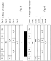
- Figure 5 and 6 depicts the difference between original and modified RLC UM PDU headers according to an example.
- a prior art RLC UM PDU comprises one or more RLC Service Data Unit (SDU) segments where all except first and/or last segments are whole SDUs.
- a segmented RLC SDU is always contained in two or more consecutive (in SN) RLC PDUs.
- the header of a prior art RLC UM PDU is shown in Figure 5 .
- the first network node 110 such as an eNB implementing embodiments herein, behave not different from a state-of-the-art eNB for original transmissions of the RLC UM PDUs. The difference is that the prior art eNB cannot re-segment the RLC UM PDUs.
- the first network node 110 e.g. an eNB implements embodiments herein, e.g. the third bit in the first octet of the header is no longer reserved, the modified header now indicates if the RLC UM PDUs are re-segmented or not.
- Non-re-segmented RLC UM PDUs has same structure as prior art PDUs except for the meaning of the third bit.
- An example of a modified header of a RLC UM PDU according to embodiments herein is shown in Figure 6 .
- third bit indicates to the second network node 120 if the RLC UM PDU is a re-segmented RLC UM PDU or not. If third bit is not set to 1 the second network node 120 performs same tasks as in prior art. But if the third bit is set to 1 then the second network node 120 treat the RLC UM PDU as a re-segmented RLC UM PDU and reads LS and SSN in order to be able to correctly re-assemble the RLC SDU segments from the received re-segmented RLC UM PDUs.
- both SI and LS may be present in the first octet in some embodiments, i.e. using two of the reserved bits.
- the SSN may cover a whole octet.
- the first network node 110 make one or more transmission attempts on the first channel such as an ULC for a number of RLC UM PDUs. Some of these arrive at the second network node 120 while other RLC UM PDUs could not be sent due to LBT was not permitting access to medium.
- the first network node 110 may try to re-send those for a number of attempts, but at some point the first network node 110 decides to re-send on a second channel such as an LC, which the first network node 110 knows that it can send on.
- the RLC UM PDU is too large to be sent in a single transmission over the second channel. This may e.g.
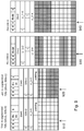
- the top-most part of the diagram indicate what is transmitted.
- the cross indicates that decoding failed.
- the lower part of the diagram illustrates schematically the RLC re-order buffer in second node 120.
- the bottom-most layer indicates the first entry in the second network node's RLC re-order buffer.
- the first network node 110 make first attempts of sending RLC UM PDU over the first channel which some may succeed to arrive at the second network node 120 while other may not successfully arrive to the second network node 120.
- the first network node 110 may get an indication that first channel is heavily loaded and may therefore decide to re-send the failed PDUs on the second channel which e.g. is lower loaded. If second channel has lower bandwidth or the radio conditions on that carrier is worse than first network node 110 need to re-segment the PDUs.
- a hole will appear in the re-order buffer of the second network node 120.
- the hole may eventually be filled due to HARQ retransmission and then the original PDU is reassembled and its contents delivered to higher layers, i.e. a layer above the layer associated with RLC. If the hole is not filled, the entire original RLC UM PDU may be discarded.
- the re-segmented RLC UM PDUs are created using ordinary segmentation procedure with the difference that the re-segmented RLC UM PDUs have the same SN as original PDU and that SI indicates re-segmented RLC UM PDUs, re-segmented RLC UM PDUs comprises an SSN indicating order of re-segmented RLC UM PDUs and that the last re-segmented RLC UM PDU comprises an indicator that it is the last re-segmented RLC UM PDU.
- each re-segmented RLC UM PDU comprises information on how to re-assemble RLC SDU segments and it also means that when the second node has received the first re-segmented RLC UM PDU it can start re-assemble the SDU segments and deliver complete SDUs to higher layers. Hence, the second network node 120 does not need to wait until all re-segmented SDUs have been received.
- the second network node 120 re-assembles a data part of the re-segmented RLC UM PDU to an ordered sequence of SDU segments, wherein each re-segmented RLC UM PDU comprises information on how to re-assemble into RLC SDU segments and when the second node 120 has received the first re-segmented RLC UM PDU starting to re-assemble the SDU segments and deliver complete SDUs in order to layer above RLC before all re-segmented SDUs has been received.
- the SDU segments sent in re-segmented RLC UM PDUs may not all be complete.
- the non-complete ones need to be re-assembled to complete SDUs using non-re-segmented RLC UM PDUs.
- a re-segmented RLC UM PDU may be re-assembled to a complete SDU.
- the second network node 120 may operate such that it receives two or more re-segmented RLC UM PDUs. Then it re-orders and re-assembles the re-segmented RLC UM PDUs to ordered SDU segments. Once, that has been done, the second node may (re-)create the un-re-segmented RLC UM PDU that first node actually re-segmented. The created un-re-segmented RLC UM PDU may then be fed to state-of-the-art re-order, re-assemble and deliver-to-higher-layer method.
- Figure 8 illustrates an example of the PDU re-segmentation in the first network node 110.
- Figure 9 illustrates an example of the re-assembling of the in Figure 8 re-segmented RLC UM PDUs in the second network node 120.
- FIG 10 an example of a PDU header 1-level of re-segmentation, a PDU header 2-level of re-segmentation and a PDU header 3-level of re-segmentation is illustrated.
- 1-bit SE is needed to indicate "a next level" and therefore in this embodiment, SSN will be one bit less.
- the E bit in first octet is set to 1 to indicate an E and LI fields following the last bit of SN.
- the E bit in second octet indicates if 4-th octet is data or an E and LI fields
- Extension bit (E) field comprises:
- the E field indicates whether Data field follows or a set of E field and LI field follows.
- the interpretation of the E field is provided in Table 6.2.2.4-1 and Table 6.2.2.4-2 below.
- Table 6.2.2.4-1 E field interpretation (for E field in the fixed part of the header) Value Description 0 Data field follows from the octet following the fixed part of the header 1
- a set of E field and LI field follows from the octet following the fixed part of the header
- Table 6.2.2.4-2 E field interpretation (for E field in the extension part of the header) Value Description 0
- Data field follows from the octet following the LI field following this E field 1
- a set of E field and LI field follows from the bit following the LI field following this E field
- the fixed part of the header is 2 octets.
- the fixed part of the header may be 3 octets.
- Length Indicator (LI) field comprises:
- the LI field indicates the length in bytes of the corresponding Data field element present in the RLC data PDU delivered/received by an UM or an AM RLC entity.
- the first LI present in the RLC data PDU header corresponds to the first Data field element present in the Data field of the RLC data PDU
- the second LI present in the RLC data PDU header corresponds to the second Data field element present in the Data field of the RLC data PDU, and so on.
- the value 0 is reserved.
- 6.2.2.6 Framing Info (FI) field comprises:
- the FI field indicates whether a RLC SDU is segmented at the beginning and/or at the end of the Data field. Specifically, the FI field indicates whether the first byte of the Data field corresponds to the first byte of a RLC SDU, and whether the last byte of the Data field corresponds to the last byte of a RLC SDU.
- the first network node 110 may comprise the following arrangement depicted in Figure 12 .
- the first network node 110 and second network node 120 are adapted to operate in a wireless communications network 100.
- the wireless communications network 100 is configured to provide a first channel and a second channel. 16.
- the first channel may be arranged to be represented by a ULC and the second channel may be arranged to be represented by an LC.
- the first channel and the second channel are arranged to be the same channel.
- the first network node 110 is configured to, e.g. by means of a deciding module 1200 configured to, when detected that the RLC UM PDU has failed to be transmitted over the first channel, decide to redirect the RLC UM PDU to be transmitted over the second channel.
- the RLC UM PDU is too large to be sent in a single transmission over the second channel.
- the first network node 110 is further configured to, e.g. by means of a dividing module 1210 configured to, divide the RLC UM PDU into two or more re-segmented RLC UM PDUs.
- the first network node 110 is further configured to, e.g. by means of a transmitting module 1220 configured to, transmit the two or more re-segmented RLC UM PDUs to the second network node 120 over the second channel.
- the transmitting module 820 may be comprised in a wireless transmitter of the first network node 110.
- Each re-segmented RLC UM PDU is arranged to comprise the following indications:
- the indications may be arranged to be comprised in a header of the re-segmented RLC UM PDU.
- the indication (a) that the PDU is re-segmented is adapted to be indicated in a first octet of the header. Further the indications (b) an order indicator related to the re-segmented RLC UM PDU, and (c) whether or not the re-segmented RLC UM PDU is a last re-segmented RLC UM PDU out of the two or more re-segmented RLC UM PDUs, are adapted to be indicated in a third octet of the header.
- the order indicator related to the re-segmented RLC UM PDU is arranged to be represented by a segment sequence number.
- the embodiments herein comprising the process of transmitting a RLC UM PDU to a second network node 120 may be implemented through one or more processors, such as a processor 1230 in the first network node 110 depicted in Figure 12 , together with computer program code for performing the functions and actions of the embodiments herein.
- the program code mentioned above may also be provided as a computer program product, for instance in the form of a data carrier carrying computer program code for performing the embodiments herein when being loaded into the first network node 110.
- One such carrier may be in the form of a CD ROM disc. It is however feasible with other data carriers such as a memory stick.
- the computer program code may furthermore be provided as pure program code on a server and downloaded to the first network node 110.
- the first network node 110 may further comprise a memory 1240 comprising one or more memory units.
- the memory 1240 comprises instructions executable by the processor 1230.
- the memory 1240 is arranged to be used to store e.g. RLC UM PDUs, re-segmented RLC UM PDUs, order indicators related to re-segmented RLC UM PDUs, data, configurations, and applications etc. to perform the methods herein when being executed in the first network node 110.
- an detecting module 1200, dividing module 1210, and transmitting module 1220 may refer to a combination of analog and digital circuits, and/or one or more processors configured with software and/or firmware, e.g. stored in the memory 1240, that when executed by the one or more processors such as the processor 1230 as described above.
- processors may be included in a single Application-Specific Integrated Circuitry (ASIC), or several processors and various digital hardware may be distributed among several separate components, whether individually packaged or assembled into a system-on-a-chip (SoC).
- ASIC Application-Specific Integrated Circuitry
- SoC system-on-a-chip
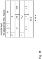
- the second network node 120 may comprise the following arrangement depicted in Figure 13 .
- second network node 120 and first network node 110 are adapted to operate in a wireless communications network 100.
- the wireless communications network 100 is configured to provide a first channel and a second channel.
- the first channel may be arranged to be represented by a ULC
- the second channel may be arranged to be represented by an LC.
- the first channel and the second channel are arranged to be the same channel.
- the second network node 120 being configured to, e.g. by means of a receiving module 1300 configured to, receive two or more re-segmented RLC UM PDUs from the first network node 110 over the second channel.
- Each re-segmented RLC UM PDU is arranged to comprise the following indications:
- the receiving module 900 may be comprised in a wireless transceiver of the second network node 120.
- the order indicator related to the re-segmented RLC UM PDU is arranged to be represented by a segment sequence number.
- the indications may be arranged to be comprised in a header of the re-segmented RLC UM PDU.
- the indication (a) that the PDU is re-segmented may be arranged to be indicated in a first octet of the header.
- the indications (b) an order indicator related to the re-segmented RLC UM PDU, and (c) whether or not the re-segmented RLC UM PDU is a last re-segmented RLC UM PDU out of the two or more re-segmented RLC UM PDUs may be arranged to be indicated in a third octet of the header.
- the second network node 120 is further configured to, e.g. by means of a re-assembling module 1310 configured to, re-assemble the two or more re-segmented RLC UM PDUs into a RLC UM PDU based on the indications.
- a re-assembling module 1310 configured to, re-assemble the two or more re-segmented RLC UM PDUs into a RLC UM PDU based on the indications.
- the second network node 120 according to any of the claims 22-29, wherein the second network node 120 is configured to re-assemble the two or more re-segmented RLC UM PDUs into a RLC UM PDU based on the indications by:
- the second network node 120 is configured to re-assembles a data part of the re-segmented RLC UM PDU to an ordered sequence of SDU segments, wherein each re-segmented RLC UM PDU comprises information on how to re-assemble into RLC SDU segments and when the second node 120 has received the first re-segmented RLC UM PDU starting to re-assemble the SDU segments and deliver complete SDUs in order to layer above RLC before all re-segmented SDUs has been received.
- the second network node 120 may further be configured to, e.g. by means of a sending module 1320 configured to, send the re-assembled RLC UM SDU segments in order to a layer above RLC.
- the second network node 120 may further be configured to, e.g. by means of a detecting module 1330 configured to, detect that a re-segmented RLC UM PDU is missing when trying to re-assembling the PDU.
- a detecting module 1330 configured to, detect that a re-segmented RLC UM PDU is missing when trying to re-assembling the PDU.
- the second network node 120 may further be configured to, e.g. by means of a keeping module 1340 configured to, keep in a buffer of the second network node (120), the received re-segmented RLC UM PDUs until the missing re-segmented RLC UM PDU has been received or until a timer expires, before the re-segmented RLC UM PDUs into one or more RLC UM SDU segments comprised in the two or more re-segmented RLC UM PDUs and sending the re-assembled RLC UM SDU segments in order to a layer above RLC.
- a keeping module 1340 configured to, keep in a buffer of the second network node (120), the received re-segmented RLC UM PDUs until the missing re-segmented RLC UM PDU has been received or until a timer expires, before the re-segmented RLC UM PDUs into one or more RLC
- the embodiments herein comprising the process of receiving a RLC UM PDU from the first network node 110 may be implemented through one or more processors, such as a processor 1350 in the second network node 120 depicted in Figure 13 , together with computer program code for performing the functions and actions of the embodiments herein.
- the program code mentioned above may also be provided as a computer program product, for instance in the form of a data carrier carrying computer program code for performing the embodiments herein when being loaded into the second network node 120.
- One such carrier may be in the form of a CD ROM disc. It is however feasible with other data carriers such as a memory stick.
- the computer program code may furthermore be provided as pure program code on a server and downloaded to the second network node 120.
- the second network node 120 may further comprise a memory 1360 comprising one or more memory units.
- the memory 1360 comprises instructions executable by the processor 1350.
- the memory 1360 is arranged to be used to store e.g. re-segmented RLC UM PDUs, order indicators related to re-segmented RLC UM PDUs, RLC UM PDUs, data, configurations, and applications etc. to perform the methods herein when being executed in the second network node 120.
- an receiving module 1300, the re-assembling module 1310, the sending module 1320, the detecting module 1330 and the keeping module 1340, described above may refer to a combination of analog and digital circuits, and/or one or more processors configured with software and/or firmware, e.g. stored in the memory 1360, that when executed by the one or more processors such as the processor 1350 as described above.
- processors may be included in a single Application-Specific Integrated Circuitry (ASIC), or several processors and various digital hardware may be distributed among several separate components, whether individually packaged or assembled into a system-on-a-chip (SoC).
- ASIC Application-Specific Integrated Circuitry
- SoC system-on-a-chip
Landscapes
- Engineering & Computer Science (AREA)
- Computer Networks & Wireless Communication (AREA)
- Signal Processing (AREA)
- Quality & Reliability (AREA)
- Mobile Radio Communication Systems (AREA)
Description
- Embodiments herein relate to a first network, a second network node and methods therein. In particular, it relates to transmitting and receiving a Radio Link Control Unacknowledged Mode Protocol Data Unit (RLC UM PDU).
- Wireless devices for communication such as terminals are also known as e.g. User Equipments (UE), mobile terminals, wireless terminals and/or mobile stations. Wireless devices are enabled to communicate wirelessly in a cellular communications network or wireless communication system, sometimes also referred to as a cellular radio system or cellular networks. The communication may be performed e.g. between two wireless devices, between a wireless device and a regular telephone and/or between a wireless device and a server, such as server providing video streaming service, via a Radio Access Network (RAN) and possibly one or more core networks, comprised within the cellular communications network.
- Wireless devices may further be referred to as mobile telephones, cellular telephones, computers, or surf plates with wireless capability, just to mention some further examples. The wireless devices in the present context may be, for example, portable, pocket-storable, hand-held, computer-comprised, or vehicle-mounted mobile devices, enabled to communicate voice and/or data, via the RAN, with another entity, such as another wireless device or a server.
- A cellular communications network covers a geographical area which is divided into cell areas, wherein each cell area being served by a base station, e.g. a Radio Base Station (RBS), which sometimes may be referred to as e.g. eNodeB (eNB), NodeB, B node, Base Transceiver Station (BTS), or AP (Access Point), depending on the technology and terminology used. The base stations may be of different classes such as e.g. macro eNodeB, home eNodeB or pico base station, based on transmission power and thereby also cell size. A cell is the geographical area where radio coverage is provided by the base station at a base station site. One base station, situated on the base station site, may serve one or several cells. Each cell may further comprise one or more antenna sites e.g. forming a combined cell or soft cell. Further, each base station may support one or several communication technologies. The base stations communicate over the air interface operating on radio frequencies with the wireless devices within range of the base stations also referred to as transmitter-receiver pairs. In the context of this disclosure, the expression Downlink (DL) is used for the transmission path from the base station to a wireless device. The expression Uplink (UL) is used for the transmission path in the opposite direction i.e. from the wireless device to the base station.
- In 3rd Generation Partnership Project (3GPP) Long Term Evolution (LTE), base stations, which may be referred to as eNodeBs or even eNBs, may be directly connected to one or more core networks.
- Universal Mobile Telecommunications System (UMTS) is a third generation mobile communication system, which evolved from the GSM, and is intended to provide improved mobile communication services based on Wideband Code Division Multiple Access (WCDMA) access technology. UMTS Terrestrial Radio Access Network (UTRAN) is essentially a radio access network using wideband code division multiple access for terminals. The 3GPP has undertaken to evolve further the UTRAN and GSM based radio access network technologies.
- 3GPP LTE radio access standard has been written in order to support high bitrates and low latency both for uplink and downlink traffic. All data transmission is in LTE is controlled by the radio base station.
- License-Assisted Access via LTE (LAA-LTE) has recently been proposed as a technology for co-existence on unlicensed carriers with, e.g., WiFi. On an unlicensed carrier all data transmissions are to be controlled by a Listen-Before-Talk (LBT) mechanism, while control and management signaling may be sent without LBT. The LBT is a functionality which means that a channel such as an unlicensed channel is assessed to be clear before transmission begins.
- Radio Link Control (RLC) Unacknowledged Mode (UM) is typically used for transmission of data between a node in a radio access network such as an eNB, and a UE, where the data packets are desired to be delivered in order and where RLC AM re-transmissions causes unacceptable long delays. UM is often used for time critical applications, for instance video streaming services, where delays due to RLC retransmissions cause larger degradation of the end user experience than packet loss. Therefore, current RLC UM protocol does neither support re-transmission nor re-segmentation.
- Using an Unlicensed LTE carrier (ULC), for a time-critical and data packet order-critical service, UM Protocol Data Unit (PDU)s typically have to be produced before LBT is initiated. Thus if the ULC is occupied by other transmissions, some of the produced PDUs cannot be sent and will be discarded. Discarded PDUs can be re-produced to be transmitted at a later time, but these transmission re-attempts need to occur within a certain time budget from first attempt depending on the application's latency requirement Since UnLicensed Channel (ULC) access is unpredictable, some packets may be entirely discarded due to that ULC is occupied during the whole time budget for these packets. These discarded RLC UM PDUs will cause too high application packet loss rate causing significant degradation of user experience. For example, if RLC UM PDUs carries streaming video packets, then even a rather small amount of RLC UM packet loss can cause freezing video too and/or cause re-buffering.
- It may be possible to use RLC AM protocol for time-critical application packet, but that would introduce RLC re-transmissions and larger RLC protocol overhead. RLC AM re-transmissions will not be beneficial for time-critical applications since a RLC AM re-transmission timers operate on a larger time-scale than the time budget and also that RLC AM cause additional overhead since receiver of the PDUs need to send status PDUs to sender.
-
WO2013086362A1 discloses a direct communication (radio cross link) between nodes (UEs) in advanced topology (LTE) applications.FIG. 9 discloses a header 900 for an RLC unacknowledged mode (UM) segment that a helper WTRU may use to perform re- segmentation on a first hop RLC UM PDU. -
US2010215006A1 proposes methods for supporting multicarrier in a radio link control (RLC) Acknowledged Mode (AM). The proposed methods reduce the processing required when scheduling information for each carrier becomes available by generating protocol data units (PDUs) in advance, and storing the PDUs in buffers associated with each carrier. -
US2009086710A1 discloses systems and methodologies of reducing overhead by designating various fields in an optimized Radio Link Control Acknowledged Mode (AM) header. Depending on communication type (e.g., VoIP, non-VoIP) such fields are different. - It is therefore an object of embodiments herein to provide an improved way of handling PDUs in a wireless communications network.
- According to a first aspect of embodiments herein, the object is achieved by a method performed by a first network node according to
claim 1, for transmitting a Radio Link Control, RLC, Unacknowledged Mode, UM, Protocol Data Unit, PDU, to a second network node. - According to a second aspect of embodiments herein, the object is achieved by a method performed by a second network node according to
claim 5, for receiving two or more re-segmented RLC, Unacknowledged Mode, UM, Protocol Data Unit, PDUs from a first network node. - According to a third aspect of embodiments herein, the object is achieved by a first network node according to claim 12 for transmitting a Radio Link Control, RLC, Unacknowledged Mode, UM, Protocol Data Unit, PDU, to a second network node..
- According to a forth aspect of embodiments herein, the object is achieved by a second network node according to claim 13, for receiving two or more re-segmented RLC, Unacknowledged Mode, UM, Protocol Data Unit, PDUs from a first network node..
- An advantage with embodiments herein is that the end user experience will degrade less when UM PDUs are not discarded if the ULC cannot be accessed , since RLC UM PDUs may e.g. be sent on a licensed more predictable carrier even though the licensed carrier has lower bandwidth or has worse radio conditions than the ULC.
- Throughout the description any references to embodiments which do not fall within the scope of the claims are to be regarded as related examples useful for understanding the invention.
- Examples of embodiments herein are described in more detail with reference to attached drawings in which:
- Figure 1
- is a schematic block diagram illustrating a wireless communications network.
- Figure 2
- is a flowchart depicting embodiments of a method in a first network node.
- Figure 3
- is a sequence diagram illustrating embodiments of a method.
- Figure 4
- is a flowchart depicting embodiments of a method in a second network node.
- Figure 5
- is a schematic diagram illustrating prior art.
- Figure 6
- is a schematic diagram illustrating embodiments herein.
- Figure 7
- is a schematic diagram illustrating embodiments herein.
- Figure 8
- is a schematic block diagram illustrating embodiments of a first network node.
- Figure 9
- is a schematic block diagram illustrating embodiments of a second network node.
- As part of developing embodiments herein, a problem will first be identified and shortly discussed.
- Since UnLicensed Channel (ULC) access is unpredictable as mentioned above, the number of discarded packets may be very high. One possible solution to avoid loss of packets would be to re-direct the PDUs to a licensed LTE carrier. This would be possible if the UM PDU is small enough to fit on the licensed LTE carrier. If the UM PDU is too large then transmissions on the licensed carrier will likely fail resulting in a loss of the PDU unless the PDUs are re-segmented into smaller PDUs. Since RLC Acknowledge Mode (AM) supports PDU re-segmentation a possible way to solve the problem would be to change from UM to AM. AM of course solves the re-segmentation problem which enable sending the re-directed PDU in smaller pieces, but this comes to the price of additional overhead. An AM header include bits for AM functionality that relates to retransmission, and sophisticated re-segmentation functionality that provide no positive performance impact for a delay sensitive application.
- Also an option to drop the PDU and rely on a re-transmission protocol on top of RLC protocol is not beneficial since such a solution could cause severe degradation of user experience where delays due to RLC retransmissions cause larger degradation of the end user experience than packet loss as mentioned above.
- This problem may also appear in licensed carriers, for instance in carrier aggregations with shared carriers where the network does not have full control of Quality of Service (QoS).
-
Figure 1 depicts awireless communications network 100 in which embodiments herein may be implemented. Thewireless communications network 100 is comprises radio networks such as LTE, Licensed Assisted Access (LAA)-LTE, WCDMA, Wimax, WiFi, Wireless Local Area Network (WLAN) networks or any other radio network or system. In some embodiments, the access to the ULC is controlled by a listen-before-talk (LBT) mechanism. - The
wireless communications network 100 provides at least two types of channels, a first channel and a second channel. The first channel may e.g. be an Unlicensed Channel (ULC) such as an Unlicensed LTE carrier, or a Licenced Channel (LC). The second channel may also be a ULC such as an Unlicensed LTE carrier, or an LC. In one particular embodiment the first channel is a ULC such as an Unlicensed LTE carrier and the second channel is an LC. In some embodiment the bandwidth of the first channel is larger than the bandwidth of the second channel. In other embodiments that radio quality is worse on second channel than the first channel. - A plurality of network nodes operates in the
wireless communications network 100, whereof only two, afirst network node 110 and asecond network node 120 are depicted inFigure 1 for simplicity. In example embodiments herein thefirst network node 110 is represented by a base station and thesecond network node 120 is represented by a user equipment. However, it may also be the other way around, i.e.first network node 110 is represented by a user equipment and thesecond network node 120 is represented by a base station. - When the
first network node 110 and thesecond network node 120 is represented by a base station, the base station may be referred to as a transmission point and may in some embodiments be a network node referred to as, eNodeB (eNB), NodeB, B node, Base Transceiver Station (BTS), AP (Access Point) or a Home Node B, a Home eNodeB depending on the technology and terminology used, or any other network node capable to communicate with a wireless device with wireless capability, or any other radio network unit capable to communicate over a radio link in a wireless communications network. - When the
first network node 110 and thesecond network node 120 is represented by a user equipment which is, in the example scenario ofFigure 1 , served by the base station, the user equipment may e.g. be a wireless device, a mobile wireless terminal, a mobile phone, a computer such as e.g. a laptop, or tablet computer, sometimes referred to as a surf plate, with wireless capabilities, or any other radio network unit capable to communicate over a radio link in a wireless communications network. Please note the term user equipment used in this document also covers other wireless terminals such as Machine to Machine (M2M) devices. - Embodiments herein use the RLC protocol in UM mode. The UM mode of RLC provides no re-transmission functionality and is suitable for delay sensitive traffic such as streaming traffic.
- UM mode of RLC provides according to embodiments herein re-segmentation and reassembly of an RLC UM, PDU. A header of the RLC UM, PDU provides indications according to embodiments herein. Please note that State of the art RLC UM provides segmentation functionality, but not re-segmentation functionality. Once a RLC UM PDU comprises one or more segments of packets above RLC, a state-of-the-art RLC UM PDU cannot be re-segmented onto two or more PDUs that together comprise all the segments contained in the original PDU.
- In the LTE user-plane protocol stack, RLC is the protocol above the Medium Access Control (MAC) protocol and below the Packet Data Convergence Protocol (PDCP). The RLC is implemented in the
first network node 110 and thesecond network node 120 - According to embodiments herein an RLC UM, PDU may be transmitted on an unlicensed carrier and a licensed carrier. As mentioned above when a data is transmitted on an unlicensed carrier it need typically to be controlled by a Listen-Before-Talk (LBT) mechanism, while a small amount of control and management signaling may be sent without LBT. A licensed carrier is a carrier that one single operator is permitted to use, which means that the network operated by the operator has full access control to the media. For an un-licensed carrier, however, is permitted to be used by anyone provided that certain rules also referred to as regulations are followed, among one rule is that a LBT mechanism is required. Without the regulated LBT mechanism such an un-licensed carrier would be almost impossible to communicate on due to that the different networks tries to access the medium in an un-coordinated manner.
- When using a high speed Unlicensed LTE carrier (ULC), for a time and data packet order critical service, RLC UM PDUs have to be produced before control of the channel can be achieved.
- Embodiments herein provides re-segmentation of RLC UM PDUs
According to embodiments herein, the RLC UM PDU header is modified to allow for RLC UM PDU re-segmentation. - Embodiments herein, which e.g. are applicable to a LAA-LTE system, provides a modified RLC UM PDU header enabling RLC UM PDUs that cannot be sent over one channel such as e.g. a ULC can be redirected to another channel such as e.g. an LC even if the LC capacity is lower than ULC capacity.
- Example embodiments of a method performed by a
first network node 110, for transmitting a Radio Link Control, RLC, Unacknowledged Mode, UM, Protocol Data Unit, PDU, to asecond network node 120 will now be described with reference to a flowchart depicted inFigure 2 and the sequence diagram depicted inFigure 3 . As mentioned thefirst network node 110 andsecond network node 120 operate in awireless communications network 100, whichwireless communications network 100 provides a first channel and a second channel. The first channel may be represented by a ULC and the second channel may be represented by an LC. However, it may also be the other way around. It may also be that both first and second channels both are ULC or both are LC. Thus in some embodiments, the first channel and the second channel are the same channel. This may e.g. be applicable in an example scenario where for example first transmission fails due to decoding failure wherein sender wish to lower the likeliness for decoding failure by sending the PDU contents using two or more transmissions, each transmission contains a piece of original PDU contents. - The method comprises the following actions, which actions may be taken in any suitable order. Dashed lines of some boxes in
Figure 2 and3 indicate that this action is not mandatory. - In an example scenario, the
first network node 110 prepares an RLC UM PDUs to be transmitted over the first channel which in this example is an ULC. A number of RLC UM PDUs may be prepared. - Some embodiments are applied on LAA-LTE where access to the ULC for example the un-licensed channel, i.e. the wireless media over which communication occurs, is controlled by the LBT mechanism. In such scenario, RLC of in the
first network node 110 may need to prepare PDUs for transmissions before knowing if access to medium is granted. Hence,Layer 2 prepares and provides RLC UM PDUs to a transmit buffer in thefirst network node 110, for a specific transmission time instance.Layer 2 is typically referred to the entity responsible how communication over the media is controlled including preparing data blocks called transport blocks that are provided toLayer 1 which encode and prepare data to be sent one the physical media. If access to medium is granted for this transmission time instance by LBT then the PDU is transmitted from the first network node to thesecond network node 120 over the first channel which in the example scenario is the ULC. Otherwise the RLC UM PDU is not sent andLayer 2 needs to make another attempt at a later transmission time instance. - One further RLC UM PDUs may be prepared for the first channel and sent to the transmit buffer in the
first network node 110. This particular embodiment relates specific to a particular timing for LAA-LTE. For LAA-LTE the timing is such thatLayer 2 in this particular embodiment needs to prepare two RLC UM PDUs for two transmission time instances untilLayer 2 gets an indication if access to medium was granted or not. Hence in this particular embodiment,Layer 2 prepares PDUs for transmission two transmission time intervals in advance. - The
first network node 110 waits for success signal from the transmitter. A success indicator is always received 2 transmission time intervals afterLayer 2 preparation. The success signal is received once per Transmission Time Interval (TTI) if there are PDUs in the transmit buffer. - The
first network node 110 detects that the RLC UM PDU has failed to be transmitted over the first channel. In the example scenario the ULC represents the first channel. This may e.g. be detected if e.g. access to media cannot be achieved within a predetermined number of attempts such as Tmax attempts. Tmax is the number of TTIs to wait before PDUs are redirected to the second channel such as e.g. to LC. Access to media refers to if the listen-before-talk mechanism did not grant access to the communication medium such as the first channel. - In other embodiments unsuccessful HARQ retransmissions which e.g. may be controlled by using a timeout timer may be used to detect that the RLC UM PDU has failed to be correctly received over the first channel, i.e. the ULC in the example scenario.
- In some embodiments a redirection which will be triggered, when detected that the RLC UM PDU has failed to be transmitted over the first channel e.g. if access to media cannot be achieved within Tmax attempts or if unsuccessful HARQ retransmissions is detected.
- Thus, according to embodiments herein, when detected that the RLC UM PDU has failed to be transmitted over the first channel, the
first network node 110 decides to redirect the RLC UM PDU to be transmitted over the second channel. In the example scenario a decision is made to redirect the RLC UM PDU from the ULC to the LC. - The RLC UM PDU is too large to be sent in a single transmission over the second channel. Therefore, the
first network node 110 divides the RLC UM PDU into two or more re-segmented RLC UM PDUs. In some embodiments the data part of the RLC UM PDU is re-assembled to an ordered sequence of Service Data Unit (SDU) segments then the re-segmented RLC UM PDUs are created using ordinary segmentation procedure with the difference that the re-segmented RLC UM PDUs have the same SN as original RLC UM PDU and that SI indicates re-segmented RLC UM PDUs, re-segmented RLC UM PDUs comprises a Segment Sequence Number (SSN) indicating order of re-segmented RLC UM PDUs and that the last re-segmented RLC UM PDU comprises an indicator, indicating that it is the last re-segmented RLC UM PDU. In other embodiments the data part and sub-header part,e.g. Octet 3 to end of PDU, of the original RLC UM PDU is partitioned into smaller pieces and the pieces ordered such that if the pieces are put together in said order then the pieces together coincide with the data and sub-header parts of the original RLC UM PDU. - Please note that the parts of a re-segmented RLC UM PDU may be referred to as re-segments since the parts may not be divided precisely at the segment borders of the original RLC UM PDU. Thus segments of a re-segmented RLC UM PDU do not necessarily coincide with segments of the original RLC UM PDU.
- The
first network node 110 transmits the two or more re-segmented RLC UM PDUs to thesecond network node 120 over the second channel. - Each re-segmented RLC UM PDU comprises the following indications:
- (a) that the PDU is re-segmented,
- (b) an order indicator related to the re-segmented RLC UM PDU, and
- (c) whether or not the re-segmented RLC UM PDU is a last re-segmented RLC UM PDU out of the two or more re-segmented RLC UM PDUs.
- The indications may be comprised in a header of the re-segmented RLC UM PDU. In order to achieve transmission of already created RLC UM PDUs e.g. on a channel with lower capacity than it was produced for, the UM PDU header is modified according to some embodiments herein.
- In some particular embodiments, the indication (a) that the PDU is re-segmented is indicated e.g. by means of a Segmentation Indicator (SI) in a first octet of the header, for example in the third bit of the first octet of the header. Further, the indications (b) an order indicator related to the re-segmented RLC UM PDU, and (c) whether or not the re-segmented RLC UM PDU is a last re-segmented RLC UM PDU out of the two or more re-segmented RLC UM PDUs, are indicated e.g. by means of a Last Segment (LS) bit in a third octet of the header. However, the indications may be contained in any suitable bit or octet of the header.
- The order indicator related to the re-segmented RLC UM PDU may be represented by a SSN which may be comprised in the third octet of the re-segmented RLC UM PDU.
- In an example scenario, one of the reserved bits is used as an SI. If the SI bit is set to 1, a LS bit and an SSN is added as
octet 3 in the header. - Thus the segments of the original RLC UM PDU may be re-segmented into two or more re-segmented RLC UM PDUs that can be sent one by one using the SSN as an indication of the order of the segments in the re-segmented RLC UM PDUs. The LS bit is set to 1 in the last re-segmented RLC UM PDU.
- Example embodiments of a method performed by the
second network node 120, for receiving two or more re-segmented RLC, Unacknowledged Mode, UM, Protocol Data Unit, PDUs from afirst network node 110, will now be described with reference to a flowchart depicted inFigure 4 and the sequence diagram depicted inFigure 3 . As mentioned above, thesecond network node 120 and thefirst network node 110 operate in awireless communications network 100. Thewireless communications network 100 provides a first channel and a second channel. - The first channel may be represented by a ULC and the second channel may be represented by an LC. However, it may also be the other way around or both may be ULC or both may be LC. In some embodiments, the first channel and the second channel are the same channel.
- In an example scenario, the
first network node 110 prepared an RLC UM PDU to be transmitted over the first channel which in this example is an ULC. However, the transmission failed and thefirst network node 110 has redirected the RLC UM PDU to be transmitted over the second channel. In this example scenario, the first channel is represented by a ULC and the second channel is represented by an LC. - The method comprises the following actions, which actions may be taken in any suitable order.
- The
second network node 120 receives two or more re-segmented RLC UM PDUs from thefirst network node 110 over the second channel. Each re-segmented RLC UM PDU comprises the following indications: - (a) that the PDU is re-segmented,
- (b) an order indicator related to the re-segmented RLC UM PDU, and
- (c) whether or not the re-segmented RLC UM PDU is a last re-segmented RLC UM PDU out of the two or more re-segmented RLC UM PDUs.
- The indications may be comprised in a header of the re-segmented RLC UM PDU. In some embodiments the indication (a) that the RLC UM PDU is re-segmented is indicated in a first octet of the header. Further, the indications (b) an order indicator related to the re-segmented RLC UM PDU, and (c) whether or not the re-segmented RLC UM PDU is a last re-segmented RLC UM PDU out of the two or more re-segmented RLC UM PDUs, may be indicated in a third octet of the header.
- The order indicator related to the re-segmented RLC UM PDU may be represented by a Segment Sequence Number (SSN).
- Please see further explanations to this action under Action 204 above.
- The
second network node 120 may detect that a re-segmented RLC UM PDU is missing when trying to re-assembling the RLC UM PDU.Action 402 and 403 will be more explained below. - When detecting that a re-segmented RLC UM PDU is missing, the
second network node 120 keeps in a buffer of thesecond network node 120, the received re-segmented RLC UM PDUs until the missing re-segmented RLC UM PDU has been received or until a timer expires, before re-assembling inAction 404 below, the re-segmented RLC UM PDUs into one or more RLC UM SDU segments comprised in the two or more re-segmented RLC UM PDUs and sending inAction 405 below, the re-assembled RLC UM SDU segments in order to a layer above RLC. The SDUs extracted from the RLC UM PDUs are sent to a layer above RLC. - The
second network node 120 re-assembles the two or more re-segmented RLC UM PDUs into a RLC UM PDU based on the indications. This may be performed such that when thesecond network node 120 has received all re-segmented RLC UM PDUs the order indicator indicates the order in which the re-segments shall be put together. In some embodiments the LI_n are indicators, SeeFigure 9 which will be described below. - The
second network node 120 may send the re-assembled RLC UM SDU segments in order to a layer above RLC. In LTE use-plane protocol stack the layer above RLC is PDCP. On sender side, a RLC UM PDU comprises one or more RLC SDU segments. For example, an RLC SDU is a PDCP PDU and a RLC SDU segment is either a whole or fractional part of a PDCP PDU. When thesecond node 120 has re-assembled a RLC UM PDU, which may be a re-segmented RLC UM PDU, it delivers whole RLC SDUs, i.e., PDCP PDUs, to higher layer such as PDCP receiving instance. - Embodiments herein will now be described and explained more in detail. The text below is applicable to and may be combined with any suitable embodiment described above.
- According to embodiments herein, the RLC UM PDU header is modified to allow for RLC UM PDU re-segmentation. To explain the modification the modified header, it will be compared to a prior art header according to the discussion below.
Figure 5 and 6 depicts the difference between original and modified RLC UM PDU headers according to an example. - A prior art RLC UM PDU comprises one or more RLC Service Data Unit (SDU) segments where all except first and/or last segments are whole SDUs. An RLC SDU is a packet or PDU related to a layer above the RLC layer in the LTE protocol stack. If the first segment for the RLC UM PDU with SN=N is a segmented SDU, then the prior SDU segment part is comprised in the last segment in the RLC UM PDU with SN=N-1. If last segment is a segmented SDU, then the first segment of the RLC UM PDU with SN=N+1 is the sequential part of the segmented SDU. Hence, a segmented RLC SDU is always contained in two or more consecutive (in SN) RLC PDUs. This means that the SN maps to specific RLC SDUs that cannot be changed once RLC UM PDUs with higher SN has been sent. The header of a prior art RLC UM PDU is shown in
Figure 5 . - The
first network node 110 such as an eNB implementing embodiments herein, behave not different from a state-of-the-art eNB for original transmissions of the RLC UM PDUs. The difference is that the prior art eNB cannot re-segment the RLC UM PDUs. When thefirst network node 110 e.g. an eNB implements embodiments herein, e.g. the third bit in the first octet of the header is no longer reserved, the modified header now indicates if the RLC UM PDUs are re-segmented or not. Non-re-segmented RLC UM PDUs has same structure as prior art PDUs except for the meaning of the third bit. Thesecond network node 120 such as auser equipment 120 implementing embodiments herein also performs prior art tasks. If thefirst network node 110 however decides to re-segment an RLC UM PDU, which a prior art eNB or user equipment cannot do, thefirst network node 110 sets the third bit of the first octet of the header to 1 and adds a third octet comprising a last segment indicator such as an LS and a segment sequence number. This third octet is preferable only present if SI=1, i.e. for re-segmented RLC UM PDUs. An example of a modified header of a RLC UM PDU according to embodiments herein is shown inFigure 6 . - This means that the header is modified in that third bit indicates to the
second network node 120 if the RLC UM PDU is a re-segmented RLC UM PDU or not. If third bit is not set to 1 thesecond network node 120 performs same tasks as in prior art. But if the third bit is set to 1 then thesecond network node 120 treat the RLC UM PDU as a re-segmented RLC UM PDU and reads LS and SSN in order to be able to correctly re-assemble the RLC SDU segments from the received re-segmented RLC UM PDUs. - Please note that both SI and LS may be present in the first octet in some embodiments, i.e. using two of the reserved bits. In such embodiments, the SSN may cover a whole octet.
- Relating to
Action 402 and 203 above, in beneficial embodiment thefirst network node 110 make one or more transmission attempts on the first channel such as an ULC for a number of RLC UM PDUs. Some of these arrive at thesecond network node 120 while other RLC UM PDUs could not be sent due to LBT was not permitting access to medium. Thefirst network node 110 may try to re-send those for a number of attempts, but at some point thefirst network node 110 decides to re-send on a second channel such as an LC, which thefirst network node 110 knows that it can send on. However, the RLC UM PDU is too large to be sent in a single transmission over the second channel. This may e.g. be since the second channel has smaller bandwidth than the first channel and the RLC UM PDU to be resent is too large to occur in a single transmission.Figure 7 shows such a scenario where RLC UM PDU with SN=0 was first attempted to be sent on ULC, which happened before SF=n, i.e. not shown inFigure 7 , but now is re-segmented. The first re-segmentedRLC UM PDU 701 is sent in SF=n over the second channel here being an LC and is received by thesecond network node 110. In this example, it cannot be delivered to higher layer since all segments not received. (SI=1 and LS = 0). -
Figure 7 shows that the second re-segmentedRLC UM PDU 702 fails, also on the second channel. In this scenario, it cannot be delivered to higher layer since all segments not received. (SI=1 and LS = 0). - The second network node receives the first re-segmented
RLC UM PDU 701 and the third re-segmentedRLC UM PDU 703 in SF=n and SF=n+2 while the second re-segmentedRLC UM PDU 702 arrives at UE in SF=n+m. - The top-most part of the diagram, indicate what is transmitted. The cross indicates that decoding failed. The lower part of the diagram illustrates schematically the RLC re-order buffer in
second node 120. The bottom-most layer indicates the first entry in the second network node's RLC re-order buffer. - In other embodiments the
first network node 110 make first attempts of sending RLC UM PDU over the first channel which some may succeed to arrive at thesecond network node 120 while other may not successfully arrive to thesecond network node 120. Thefirst network node 110 may get an indication that first channel is heavily loaded and may therefore decide to re-send the failed PDUs on the second channel which e.g. is lower loaded. If second channel has lower bandwidth or the radio conditions on that carrier is worse thanfirst network node 110 need to re-segment the PDUs. - For example, at SF=n-1 an indication from
Layer 1 is received that RLC UM PDU with SN=0 could not be sent over the first channel being a ULC. The RLC UM PDU is then re-segmented into 3 re-segmented RLC UM PDUs of which the first re-segmented RLC UM PDU, SSN=0, is transmitted over the second channel being an LC at SF=n. The next re-segmented RLC UM PDU is transmitted at SF=n+1, and the last re-segmented RLC UM PDU, LS=1, at SF=n+2. - If the transmission of segment SSN=1 fails, a hole will appear in the re-order buffer of the
second network node 120. The hole may eventually be filled due to HARQ retransmission and then the original PDU is reassembled and its contents delivered to higher layers, i.e. a layer above the layer associated with RLC. If the hole is not filled, the entire original RLC UM PDU may be discarded. - In other embodiments wherein the data part is re-assembled to an ordered sequence of SDU segments then the re-segmented RLC UM PDUs are created using ordinary segmentation procedure with the difference that the re-segmented RLC UM PDUs have the same SN as original PDU and that SI indicates re-segmented RLC UM PDUs, re-segmented RLC UM PDUs comprises an SSN indicating order of re-segmented RLC UM PDUs and that the last re-segmented RLC UM PDU comprises an indicator that it is the last re-segmented RLC UM PDU. In such embodiments, some of RLC SDUs contained in the original RLC UM PDU can be delivered to higher layer even if some of the re-segmented RLC UM PDUs are lost. In such embodiments, each re-segmented RLC UM PDU comprises information on how to re-assemble RLC SDU segments and it also means that when the second node has received the first re-segmented RLC UM PDU it can start re-assemble the SDU segments and deliver complete SDUs to higher layers. Hence, the
second network node 120 does not need to wait until all re-segmented SDUs have been received. - Thus in some embodiments the
second network node 120 re-assembles a data part of the re-segmented RLC UM PDU to an ordered sequence of SDU segments, wherein each re-segmented RLC UM PDU comprises information on how to re-assemble into RLC SDU segments and when thesecond node 120 has received the first re-segmented RLC UM PDU starting to re-assemble the SDU segments and deliver complete SDUs in order to layer above RLC before all re-segmented SDUs has been received. - In some embodiments the SDU segments sent in re-segmented RLC UM PDUs may not all be complete. The non-complete ones need to be re-assembled to complete SDUs using non-re-segmented RLC UM PDUs.
- In some embodiments the RLC UM SDU segments in a non-re-segmented RLC UM PDU, in these embodiments, a re-segmented RLC UM PDU may be re-assembled to a complete SDU.
- In some embodiments, the
second network node 120 may operate such that it receives two or more re-segmented RLC UM PDUs. Then it re-orders and re-assembles the re-segmented RLC UM PDUs to ordered SDU segments. Once, that has been done, the second node may (re-)create the un-re-segmented RLC UM PDU that first node actually re-segmented. The created un-re-segmented RLC UM PDU may then be fed to state-of-the-art re-order, re-assemble and deliver-to-higher-layer method. - Relating to Action 203 above,
Figure 8 illustrates an example of the PDU re-segmentation in thefirst network node 110. - Relating to
Action 404 above,Figure 9 illustrates an example of the re-assembling of the inFigure 8 re-segmented RLC UM PDUs in thesecond network node 120. - Relating to re-segmented RLC UM PDU 910, FI=01 indicates that last segment of this PDU shall be re-assembled with first segment of next PDU. FI=01 also indicates that first segment is a complete SDU.
- Relating to re-segmented
RLC UM PDU 920, FI=11 indicates that first segment of this PDU shall be re-assembled with last segment of previous PDU, and that last segment of this PDU shall be re-assembled with first segment of next PDU. - Relating to re-segmented
RLC UM PDU 930, FI=10 indicates that first segment of this PDU shall be re-assembled with last segment of previous PDU, and also that two following segments are complete. - Relating to re-segmented
RLC UM PDU 940, FI=01 indicates that last segment of this PDU shall be re-assembled with first segment of next PDU, and also indicating that the first two segments are complete. - In
Figure 10 an example of a PDU header 1-level of re-segmentation, a PDU header 2-level of re-segmentation and a PDU header 3-level of re-segmentation is illustrated. According to some embodiments, to support multi-level re-segmentation 1-bit SE is needed to indicate "a next level" and therefore in this embodiment, SSN will be one bit less. - SE field interpretation:
- The
value 0 indicates: A set of LS, SE, SSN fields are not following the last bit of the SSN following this bit. - The
value 1 indicates: A set of LS, SE, SSN fields are following the last bit of the SSN following this bit. - In a further embodiment depicted in
Figure 11 , to indicate re-segmented RLC UM PDU, the E bit in first octet is set to 1 to indicate an E and LI fields following the last bit of SN. In state-of-the-art, LI = 0 is reserved, but in embodiments herein thevalue 0 indicates re-segmented RLC UM PDU and presence of LS and SSN field. The E bit in second octet indicates if 4-th octet is data or an E and LI fields - Referring to 3GPP TS 36.322 Section 6.2.2. In 6.2.2.4 the Extension bit (E) field comprises:
- The E field indicates whether Data field follows or a set of E field and LI field follows. The interpretation of the E field is provided in Table 6.2.2.4-1 and Table 6.2.2.4-2 below.
Table 6.2.2.4-1: E field interpretation (for E field in the fixed part of the header) Value Description 0 Data field follows from the octet following the fixed part of the header 1 A set of E field and LI field follows from the octet following the fixed part of the header Table 6.2.2.4-2: E field interpretation (for E field in the extension part of the header) Value Description 0 Data field follows from the octet following the LI field following this E field 1 A set of E field and LI field follows from the bit following the LI field following this E field - Please note that in state-of-the-art the fixed part of the header is 2 octets. In embodiments herein (SI=1) the fixed part of the header may be 3 octets.
- In 6.2.2.5 Length Indicator (LI) field comprises:
- The LI field indicates the length in bytes of the corresponding Data field element present in the RLC data PDU delivered/received by an UM or an AM RLC entity. The first LI present in the RLC data PDU header corresponds to the first Data field element present in the Data field of the RLC data PDU, the second LI present in the RLC data PDU header corresponds to the second Data field element present in the Data field of the RLC data PDU, and so on. The
value 0 is reserved. - In 6.2.2.6 Framing Info (FI) field comprises:
- The FI field indicates whether a RLC SDU is segmented at the beginning and/or at the end of the Data field. Specifically, the FI field indicates whether the first byte of the Data field corresponds to the first byte of a RLC SDU, and whether the last byte of the Data field corresponds to the last byte of a RLC SDU.
- The interpretation of the FI field is provided in Table 6.2.2.6-1.
Table 6.2.2.6-1: FI field interpretation Value Description 00 First byte of the Data field corresponds to the first byte of a RLC SDU. Last byte of the Data field corresponds to the last byte of a RLC SDU. 01 First byte of the Data field corresponds to the first byte of a RLC SDU. Last byte of the Data field does not correspond to the last byte of a RLC SDU. 10 First byte of the Data field does not correspond to the first byte of a RLC SDU Last byte of the Data field corresponds to the last byte of a RLC SDU. 11 First byte of the Data field does not correspond to the first byte of a RLC SDU Last byte of the Data field does not correspond to the last byte of a RLC SDU. - To perform the method actions for transmitting a RLC UM PDU to the
second network node 120 described above in relation toFigure 2 and3 , thefirst network node 110 may comprise the following arrangement depicted inFigure 12 . Thefirst network node 110 andsecond network node 120 are adapted to operate in awireless communications network 100. Thewireless communications network 100 is configured to provide a first channel and a second channel. 16. The first channel may be arranged to be represented by a ULC and the second channel may be arranged to be represented by an LC. - In some embodiments, the first channel and the second channel are arranged to be the same channel.
- The
first network node 110 is configured to, e.g. by means of a decidingmodule 1200 configured to, when detected that the RLC UM PDU has failed to be transmitted over the first channel, decide to redirect the RLC UM PDU to be transmitted over the second channel. The RLC UM PDU is too large to be sent in a single transmission over the second channel. - The
first network node 110 is further configured to, e.g. by means of adividing module 1210 configured to, divide the RLC UM PDU into two or more re-segmented RLC UM PDUs. - The
first network node 110 is further configured to, e.g. by means of atransmitting module 1220 configured to, transmit the two or more re-segmented RLC UM PDUs to thesecond network node 120 over the second channel. The transmitting module 820 may be comprised in a wireless transmitter of thefirst network node 110. Each re-segmented RLC UM PDU is arranged to comprise the following indications: - (a) that the PDU is re-segmented,
- (b) an order indicator related to the re-segmented RLC UM PDU, and
- (c) whether or not the re-segmented RLC UM PDU is a last re-segmented RLC UM PDU out of the two or more re-segmented RLC UM PDUs.
- The indications may be arranged to be comprised in a header of the re-segmented RLC UM PDU.
- The indication (a) that the PDU is re-segmented is adapted to be indicated in a first octet of the header. Further the indications (b) an order indicator related to the re-segmented RLC UM PDU, and (c) whether or not the re-segmented RLC UM PDU is a last re-segmented RLC UM PDU out of the two or more re-segmented RLC UM PDUs, are adapted to be indicated in a third octet of the header.
- In some embodiments, the order indicator related to the re-segmented RLC UM PDU is arranged to be represented by a segment sequence number.
- The embodiments herein comprising the process of transmitting a RLC UM PDU to a
second network node 120 may be implemented through one or more processors, such as aprocessor 1230 in thefirst network node 110 depicted inFigure 12 , together with computer program code for performing the functions and actions of the embodiments herein. The program code mentioned above may also be provided as a computer program product, for instance in the form of a data carrier carrying computer program code for performing the embodiments herein when being loaded into thefirst network node 110. One such carrier may be in the form of a CD ROM disc. It is however feasible with other data carriers such as a memory stick. The computer program code may furthermore be provided as pure program code on a server and downloaded to thefirst network node 110. - The
first network node 110 may further comprise amemory 1240 comprising one or more memory units. Thememory 1240 comprises instructions executable by theprocessor 1230. Thememory 1240 is arranged to be used to store e.g. RLC UM PDUs, re-segmented RLC UM PDUs, order indicators related to re-segmented RLC UM PDUs, data, configurations, and applications etc. to perform the methods herein when being executed in thefirst network node 110. - Those skilled in the art will also appreciate that the an detecting
module 1200, dividingmodule 1210, and transmittingmodule 1220, described above may refer to a combination of analog and digital circuits, and/or one or more processors configured with software and/or firmware, e.g. stored in thememory 1240, that when executed by the one or more processors such as theprocessor 1230 as described above. One or more of these processors, as well as the other digital hardware, may be included in a single Application-Specific Integrated Circuitry (ASIC), or several processors and various digital hardware may be distributed among several separate components, whether individually packaged or assembled into a system-on-a-chip (SoC). - To perform the method actions for receiving two or more re-segmented RLC UM PDUs from the
first network node 110 described above in relation toFigure 3 and4 , thesecond network node 120 may comprise the following arrangement depicted inFigure 13 . As mentioned abovesecond network node 120 andfirst network node 110 are adapted to operate in awireless communications network 100. Thewireless communications network 100 is configured to provide a first channel and a second channel. The first channel may be arranged to be represented by a ULC, and the second channel may be arranged to be represented by an LC. In some embodiments, the first channel and the second channel are arranged to be the same channel. - The
second network node 120 being configured to, e.g. by means of areceiving module 1300 configured to, receive two or more re-segmented RLC UM PDUs from thefirst network node 110 over the second channel. Each re-segmented RLC UM PDU is arranged to comprise the following indications: - (a) that the PDU is re-segmented,
- (b) an order indicator related to the re-segmented RLC UM PDU, and
- (c) whether or not the re-segmented RLC UM PDU is a last re-segmented RLC UM PDU out of the two or more re-segmented RLC UM PDUs.
- The receiving module 900 may be comprised in a wireless transceiver of the
second network node 120. - In some embodiments the order indicator related to the re-segmented RLC UM PDU is arranged to be represented by a segment sequence number.
- The indications may be arranged to be comprised in a header of the re-segmented RLC UM PDU. The indication (a) that the PDU is re-segmented may be arranged to be indicated in a first octet of the header. Further, the indications (b) an order indicator related to the re-segmented RLC UM PDU, and (c) whether or not the re-segmented RLC UM PDU is a last re-segmented RLC UM PDU out of the two or more re-segmented RLC UM PDUs, may be arranged to be indicated in a third octet of the header.
- The
second network node 120 is further configured to, e.g. by means of are-assembling module 1310 configured to, re-assemble the two or more re-segmented RLC UM PDUs into a RLC UM PDU based on the indications. - In some embodiments, the
second network node 120 according to any of the claims 22-29, wherein thesecond network node 120 is configured to re-assemble the two or more re-segmented RLC UM PDUs into a RLC UM PDU based on the indications by: - re-assembling a data part of the RLC UM PDU to an ordered sequence of Service Data Unit, SDU, segments,
- creating the re-segmented RLC UM PDUs, wherein each re-segmented RLC UM PDU is adapted to comprise information on how to re-assemble RLC SDU segments. The
second network node 120 is configured to, when thesecond node 120 has received the first re-segmented RLC UM PDU, start to re-assemble the SDU segments and deliver complete SDUs to higher layers before all re-segmented SDUs has been received. - Thus in some embodiments the
second network node 120 is configured to re-assembles a data part of the re-segmented RLC UM PDU to an ordered sequence of SDU segments, wherein each re-segmented RLC UM PDU comprises information on how to re-assemble into RLC SDU segments and when thesecond node 120 has received the first re-segmented RLC UM PDU starting to re-assemble the SDU segments and deliver complete SDUs in order to layer above RLC before all re-segmented SDUs has been received. - The
second network node 120 may further be configured to, e.g. by means of asending module 1320 configured to, send the re-assembled RLC UM SDU segments in order to a layer above RLC. - The
second network node 120 may further be configured to, e.g. by means of a detectingmodule 1330 configured to, detect that a re-segmented RLC UM PDU is missing when trying to re-assembling the PDU. - The
second network node 120 may further be configured to, e.g. by means of akeeping module 1340 configured to, keep in a buffer of the second network node (120), the received re-segmented RLC UM PDUs until the missing re-segmented RLC UM PDU has been received or until a timer expires, before the re-segmented RLC UM PDUs into one or more RLC UM SDU segments comprised in the two or more re-segmented RLC UM PDUs and sending the re-assembled RLC UM SDU segments in order to a layer above RLC. - The embodiments herein comprising the process of receiving a RLC UM PDU from the
first network node 110 may be implemented through one or more processors, such as aprocessor 1350 in thesecond network node 120 depicted inFigure 13 , together with computer program code for performing the functions and actions of the embodiments herein. The program code mentioned above may also be provided as a computer program product, for instance in the form of a data carrier carrying computer program code for performing the embodiments herein when being loaded into thesecond network node 120. One such carrier may be in the form of a CD ROM disc. It is however feasible with other data carriers such as a memory stick. The computer program code may furthermore be provided as pure program code on a server and downloaded to thesecond network node 120. - The
second network node 120 may further comprise amemory 1360 comprising one or more memory units. Thememory 1360 comprises instructions executable by theprocessor 1350. - The
memory 1360 is arranged to be used to store e.g. re-segmented RLC UM PDUs, order indicators related to re-segmented RLC UM PDUs, RLC UM PDUs, data, configurations, and applications etc. to perform the methods herein when being executed in thesecond network node 120. - Those skilled in the art will also appreciate that the an
receiving module 1300, there-assembling module 1310, the sendingmodule 1320, the detectingmodule 1330 and thekeeping module 1340, described above may refer to a combination of analog and digital circuits, and/or one or more processors configured with software and/or firmware, e.g. stored in thememory 1360, that when executed by the one or more processors such as theprocessor 1350 as described above. One or more of these processors, as well as the other digital hardware, may be included in a single Application-Specific Integrated Circuitry (ASIC), or several processors and various digital hardware may be distributed among several separate components, whether individually packaged or assembled into a system-on-a-chip (SoC). - When using the word "comprise" or "comprising" it shall be interpreted as nonlimiting, i.e. meaning "consist at least of".
- The embodiments herein describe preferred embodiments. The scope of the invention is defined by the appending claims.
Claims (13)
- A method performed by a first network node (110), for transmitting a Radio Link Control, RLC, Unacknowledged Mode, UM, Protocol Data Unit, PDU, to a second network node (120), which first network node (110) and second network node (120) operate in a third generation partnership project, 3GPP, wireless communications network (100), which 3GPP wireless communications network (100) provides a first channel and a second channel, the method comprising:when detected that the RLC UM PDU has failed to be transmitted over the first channel, wherein the first channel is represented by an UnLicensed Channel, ULC, deciding (202) to redirect the RLC UM PDU to be transmitted over the second channel, and when RLC UM PDU is too large to be sent in a single transmission over the second channel, wherein the second channel is represented by a Licenced Channel, LC, anddividing (203) the RLC UM PDU into two or more re-segmented RLC UM PDUs,transmitting (204) the two or more re-segmented RLC UM PDUs to the second network node (120) over the second channel, ,wherein each re-segmented RLC UM PDU comprises the following indications:(a) that the PDU is re-segmented,(b) an order indicator related to the re-segmented RLC UM PDU, and(c) whether or not the re-segmented RLC UM PDU is a last re-segmented RLC UM PDU out of the two or more re-segmented RLC UM PDUs.
- The method according to claim 1, wherein the indications are comprised in a header of the re-segmented RLC UM PDU.
- The method according to claim 2, wherein the indications:(a) that the PDU is re-segmented is indicated in a first octet of the header, and,(b) an order indicator related to the re-segmented RLC UM PDU, and (c) whether or not the re-segmented RLC UM PDU is a last re-segmented RLC UM PDU out of the two or more re-segmented RLC UM PDUs, are indicated in a third octet of the header.
- The method according to any of the claims 1-3, wherein the order indicator related to the re-segmented RLC UM PDU is represented by a segment sequence number.
- A method performed by a second network node (120), for receiving two or more re-segmented_Radio Link Control, RLC, Unacknowledged Mode, UM, Protocol Data Unit, PDUs from a first network node (110), which second network node (120) and first network node (110) operate in a third generation partnership project, 3GPP, wireless communications network (100), which 3GPP wireless communications network (100) provides a first channel and a second channel, the method comprising:receiving (401), when the RLC UM PDU has failed to be received over the first channel, two or more re-segmented RLC UM PDUs from the first network node (110) over the second channel, wherein the first channel is represented by an UnLicensed Channel, ULC, and wherein the second channel is represented by a Licenced Channel, LC,wherein each re-segmented RLC UM PDU comprises the following indications:(a) that the PDU is re-segmented,(b) an order indicator related to the re-segmented RLC UM PDU, and(c) whether or not the re-segmented RLC UM PDU is a last re-segmented RLC UM PDU out of the two or more re-segmented RLC UM PDUs, andre-assembling (404) the two or more re-segmented RLC UM PDUs into RLC UM Service Data Unit, SDU, segments based on the indications.
- The method according to claim 5, further comprising
sending (405) the re-assembled RLC UM SDU segments in order to a layer above RLC. - The method according to any of the claims 5-6, further comprising
detecting (402) that a re-segmented RLC UM PDU is missing when trying to re-assembling the RLC UM PDU, and
keeping (403) in a buffer of the second network node (120), the received re-segmented RLC UM PDUs until the missing re-segmented RLC UM PDU has been received or until a timer expires, before re-assembling (404) the re-segmented RLC UM PDUs into one or more RLC UM SDU segments comprised in the two or more re-segmented RLC UM PDUs and sending (405) the re-assembled RLC UM SDU segments in order to a layer above RLC. - The method according to any of the claims 5-7, wherein the indications are comprised in a header of the re-segmented RLC UM PDU.
- The method according to any of the claims 5-8, wherein the indications(a) that the re-segmented RLC UM PDUs is re-segmented is indicated in a first octet of the header, and(b) an order indicator related to the re-segmented RLC UM PDU, and (c) whether or not the re-segmented RLC UM PDU is a last re-segmented RLC UM PDU out of the two or more re-segmented RLC UM PDUs, are indicated in a third octet of the header.
- The method according to any of the claims 5-9, wherein the order indicator related to the re-segmented RLC UM PDU is represented by a segment sequence number.
- The method according to any of the claims 5-10, wherein the re-assembling (404) the two or more re-segmented RLC UM PDUs into a RLC UM PDU based on the indications comprises:re-assembling a data part of the re-segmented RLC UM PDU to an ordered sequence of Service Data Unit, SDU, segmentswherein each re-segmented RLC UM PDU comprises information on how to re-assemble into RLC SDU segments and when the second node (120) has received the first re-segmented RLC UM PDU starting to re-assemble the SDU segments and deliver complete SDUs in order to layer above RLC before all re-segmented SDUs has been received.
- A first network node (110) for transmitting a Radio Link Control, RLC, Unacknowledged Mode, UM, Protocol Data Unit, PDU, to a second network node (120), which first network node (110) and second network node (120) are adapted to operate in a third generation partnership project, 3GPP, wireless communications network (100), which 3GPP wireless communications network (100) is configured to provide a first channel and a second channel, the first network node (110) being configured to:when detected that the RLC UM PDU has failed to be transmitted over the first channel, wherein the first channel is represented by an UnLicensed Channel, ULC, decide to redirect the RLC UM PDU to be transmitted over the second channel, and when RLC UM PDU is too large to be sent in a single transmission over the second channel, wherein the second channel is represented by a Licenced Channel, LC, anddivide the RLC UM PDU into two or more re-segmented RLC UM PDUs,transmit the two or more re-segmented RLC UM PDUs to the second network node (120) over the second channel,wherein each re-segmented RLC UM PDU is arranged to comprise the following indications:(a) that the PDU is re-segmented,(b) an order indicator related to the re-segmented RLC UM PDU, and(c) whether or not the re-segmented RLC UM PDU is a last re-segmented RLC UM PDU out of the two or more re-segmented RLC UM PDUs.
- A second network node (120) for receiving two or more re-segmented Radio Link Control, RLC, Unacknowledged Mode, UM, Protocol Data Unit, PDUs from a first network node (110), which second network node (120) and first network node (110) are adapted to operate in a third generation partnership project, 3GPP, wireless communications network (100), which 3GPP wireless communications network (100) is configured to provide a first channel and a second channel, the second network node (120) being configured to:receive, when the RLC UM PDU has failed to be received over the first channel, two or more re-segmented RLC UM PDUs from the first network node (110) over the second channel, wherein the first channel is represented by an UnLicensed Channel, ULC, and wherein the second channel is represented by a Licenced Channel, LC,wherein each re-segmented RLC UM PDU is arranged to comprise the following indications:(a) that the PDU is re-segmented,(b) an order indicator related to the re-segmented RLC UM PDU, and(c) whether or not the re-segmented RLC UM PDU is a last re-segmented RLC UM PDU out of the two or more re-segmented RLC UM PDUs,and wherein the second network node (120) further is configured to:
re-assemble the two or more re-segmented RLC UM PDUs into RLC UM Service Data Unit, SDU, segments based on the indications.
Applications Claiming Priority (1)
| Application Number | Priority Date | Filing Date | Title |
|---|---|---|---|
| PCT/SE2014/051389 WO2016080877A1 (en) | 2014-11-20 | 2014-11-20 | First network node, second network node and methods for transmitting and receiving a protocol data unit |
Publications (3)
| Publication Number | Publication Date |
|---|---|
| EP3221990A1 EP3221990A1 (en) | 2017-09-27 |
| EP3221990A4 EP3221990A4 (en) | 2017-11-22 |
| EP3221990B1 true EP3221990B1 (en) | 2018-10-10 |
Family
ID=56014277
Family Applications (1)
| Application Number | Title | Priority Date | Filing Date |
|---|---|---|---|
| EP14906263.0A Not-in-force EP3221990B1 (en) | 2014-11-20 | 2014-11-20 | First network node, second network node and methods for transmitting and receiving a protocol data unit |
Country Status (3)
| Country | Link |
|---|---|
| US (1) | US10396931B2 (en) |
| EP (1) | EP3221990B1 (en) |
| WO (1) | WO2016080877A1 (en) |
Families Citing this family (11)
| Publication number | Priority date | Publication date | Assignee | Title |
|---|---|---|---|---|
| CN110505656B (en) * | 2016-09-30 | 2020-07-24 | 华为技术有限公司 | Data processing method, device and system |
| CN108012289B (en) * | 2016-11-01 | 2022-11-22 | 中兴通讯股份有限公司 | PDU (protocol data Unit) sending method and device and PDU receiving method and device |
| KR102464567B1 (en) | 2017-01-16 | 2022-11-09 | 삼성전자 주식회사 | Method and apparatus for data processing in a wireless communication system |
| CN108668320B (en) * | 2017-03-31 | 2020-11-03 | 维沃移动通信有限公司 | Segment packing method and receiving end |
| KR102614500B1 (en) * | 2017-04-25 | 2023-12-18 | 엘지전자 주식회사 | Method and apparatus for transmitting data units |
| CN108810985B (en) | 2017-05-05 | 2024-04-12 | 华为技术有限公司 | Data transmission method, device, equipment and system |
| EP3493586B1 (en) * | 2017-05-19 | 2020-08-26 | Guangdong Oppo Mobile Telecommunications Corp., Ltd. | Method and device for data reception and processing of radio link control layer |
| US10602563B2 (en) | 2017-06-09 | 2020-03-24 | Samsung Electronics Co., Ltd. | Method and apparatus for supporting RLC UM mode operation in next generation mobile communication system |
| US10694422B2 (en) * | 2017-08-10 | 2020-06-23 | Samsung Electronics Co., Ltd. | Method and apparatus for data processing in wireless communication system |
| CN110139242B (en) * | 2018-02-09 | 2021-03-05 | 电信科学技术研究院有限公司 | Data transmission method, device, equipment and computer readable storage medium |
| WO2021243535A1 (en) * | 2020-06-02 | 2021-12-09 | Qualcomm Incorporated | Radio link control layer feedback reporting for rateless codes |
Family Cites Families (8)
| Publication number | Priority date | Publication date | Assignee | Title |
|---|---|---|---|---|
| US6842461B2 (en) * | 2002-03-08 | 2005-01-11 | Motorola, Inc. | Method and apparatus for data retransmission within a communication system |
| KR101000699B1 (en) * | 2004-04-19 | 2010-12-10 | 엘지전자 주식회사 | Data handling method in radio linl comtrol layer |
| US7768961B2 (en) * | 2005-05-03 | 2010-08-03 | Interdigital Technology Corporation | Wireless communication method and apparatus for reliably transmitting data |
| US8873471B2 (en) * | 2007-10-01 | 2014-10-28 | Qualcomm Incorporated | Method and apparatus for implementing LTE RLC header formats |
| US8693384B2 (en) * | 2008-05-29 | 2014-04-08 | Htc Corporation | Method for dynamic packet retransmission for radio link control layer in a wireless communications system |
| US8638773B2 (en) | 2009-01-29 | 2014-01-28 | Qualcomm Incorporated | RLC for multi-carrier LTE systems |
| WO2013086362A1 (en) | 2011-12-08 | 2013-06-13 | Interdigital Patent Holdings, Inc. | Direct communication between wireless transmit/receive units (wtrus) in advanced topology (at) applications |
| US10237911B2 (en) * | 2014-01-30 | 2019-03-19 | Intel IP Corporation | Packet data convergence protocol (PDCP) enhancements in dual-connectivity networks |
-
2014
- 2014-11-20 US US15/520,585 patent/US10396931B2/en active Active
- 2014-11-20 EP EP14906263.0A patent/EP3221990B1/en not_active Not-in-force
- 2014-11-20 WO PCT/SE2014/051389 patent/WO2016080877A1/en active Application Filing
Non-Patent Citations (1)
| Title |
|---|
| None * |
Also Published As
| Publication number | Publication date |
|---|---|
| WO2016080877A1 (en) | 2016-05-26 |
| US20170310421A1 (en) | 2017-10-26 |
| EP3221990A1 (en) | 2017-09-27 |
| US10396931B2 (en) | 2019-08-27 |
| EP3221990A4 (en) | 2017-11-22 |
Similar Documents
| Publication | Publication Date | Title |
|---|---|---|
| EP3221990B1 (en) | First network node, second network node and methods for transmitting and receiving a protocol data unit | |
| US10805430B2 (en) | Evolved data compression scheme signaling | |
| US11184801B2 (en) | Method and device for transmitting data unit | |
| EP3240328B1 (en) | Efficient discard mechanism in small cell deployment | |
| EP2290863B1 (en) | Wireless communication method for transmitting a sequence of data units between a wireless device and a network | |
| EP2266242B1 (en) | Method and apparatus for link control in a wireless communication system | |
| JP5438115B2 (en) | RLC segmentation for carrier aggregation | |
| US10355826B2 (en) | Communication methods performed by secondary base station and master base station and associated base stations | |
| US8619760B2 (en) | Method of providing circuit switched (SC) service using high-speed downlink packet access (HSDPA) or high-speed uplink packet access (HSUPA) | |
| US10638353B2 (en) | Evolved data compression scheme for unreliable transmission modes | |
| JP2020520150A (en) | Radio link control status reporting | |
| JP6628227B2 (en) | Method and apparatus for improving communication quality in a mobile communication network | |
| US20180131640A1 (en) | Techniques for encoding and decoding multiple acknowledgement signals in new radio | |
| WO2022203581A1 (en) | Methods and apparatus for disabled harq processes | |
| JP5124591B2 (en) | Method for displaying consecutive data units in RAN | |
| WO2024087585A1 (en) | Method and apparatus of data transmission using protocol data unit set discard timers |
Legal Events
| Date | Code | Title | Description |
|---|---|---|---|
| STAA | Information on the status of an ep patent application or granted ep patent |
Free format text: STATUS: THE INTERNATIONAL PUBLICATION HAS BEEN MADE |
|
| PUAI | Public reference made under article 153(3) epc to a published international application that has entered the european phase |
Free format text: ORIGINAL CODE: 0009012 |
|
| STAA | Information on the status of an ep patent application or granted ep patent |
Free format text: STATUS: REQUEST FOR EXAMINATION WAS MADE |
|
| 17P | Request for examination filed |
Effective date: 20170406 |
|
| AK | Designated contracting states |
Kind code of ref document: A1 Designated state(s): AL AT BE BG CH CY CZ DE DK EE ES FI FR GB GR HR HU IE IS IT LI LT LU LV MC MK MT NL NO PL PT RO RS SE SI SK SM TR |
|
| AX | Request for extension of the european patent |
Extension state: BA ME |
|
| STAA | Information on the status of an ep patent application or granted ep patent |
Free format text: STATUS: EXAMINATION IS IN PROGRESS |
|
| A4 | Supplementary search report drawn up and despatched |
Effective date: 20171019 |
|
| RIC1 | Information provided on ipc code assigned before grant |
Ipc: H04L 1/18 20060101AFI20171013BHEP Ipc: H04L 12/46 20060101ALI20171013BHEP Ipc: H04L 1/00 20060101ALI20171013BHEP Ipc: H04W 92/02 20090101ALI20171013BHEP Ipc: H04L 12/801 20130101ALI20171013BHEP |
|
| 17Q | First examination report despatched |
Effective date: 20171109 |
|
| DAX | Request for extension of the european patent (deleted) | ||
| REG | Reference to a national code |
Ref country code: DE Ref legal event code: R079 Ref document number: 602014034104 Country of ref document: DE Free format text: PREVIOUS MAIN CLASS: H04L0001080000 Ipc: H04L0001160000 |
|
| GRAP | Despatch of communication of intention to grant a patent |
Free format text: ORIGINAL CODE: EPIDOSNIGR1 |
|
| STAA | Information on the status of an ep patent application or granted ep patent |
Free format text: STATUS: GRANT OF PATENT IS INTENDED |
|
| RIC1 | Information provided on ipc code assigned before grant |
Ipc: H04W 80/02 20090101ALI20180629BHEP Ipc: H04L 1/16 20060101AFI20180629BHEP Ipc: H04L 1/18 20060101ALI20180629BHEP |
|
| INTG | Intention to grant announced |
Effective date: 20180727 |
|
| GRAS | Grant fee paid |
Free format text: ORIGINAL CODE: EPIDOSNIGR3 |
|
| GRAA | (expected) grant |
Free format text: ORIGINAL CODE: 0009210 |
|
| STAA | Information on the status of an ep patent application or granted ep patent |
Free format text: STATUS: THE PATENT HAS BEEN GRANTED |
|
| AK | Designated contracting states |
Kind code of ref document: B1 Designated state(s): AL AT BE BG CH CY CZ DE DK EE ES FI FR GB GR HR HU IE IS IT LI LT LU LV MC MK MT NL NO PL PT RO RS SE SI SK SM TR |
|
| REG | Reference to a national code |
Ref country code: GB Ref legal event code: FG4D |
|
| REG | Reference to a national code |
Ref country code: CH Ref legal event code: EP Ref country code: AT Ref legal event code: REF Ref document number: 1052489 Country of ref document: AT Kind code of ref document: T Effective date: 20181015 |
|
| REG | Reference to a national code |
Ref country code: DE Ref legal event code: R096 Ref document number: 602014034104 Country of ref document: DE Ref country code: IE Ref legal event code: FG4D |
|
| REG | Reference to a national code |
Ref country code: NL Ref legal event code: MP Effective date: 20181010 |
|
| REG | Reference to a national code |
Ref country code: LT Ref legal event code: MG4D |
|
| REG | Reference to a national code |
Ref country code: AT Ref legal event code: MK05 Ref document number: 1052489 Country of ref document: AT Kind code of ref document: T Effective date: 20181010 |
|
| PG25 | Lapsed in a contracting state [announced via postgrant information from national office to epo] |
Ref country code: NL Free format text: LAPSE BECAUSE OF FAILURE TO SUBMIT A TRANSLATION OF THE DESCRIPTION OR TO PAY THE FEE WITHIN THE PRESCRIBED TIME-LIMIT Effective date: 20181010 |
|
| PG25 | Lapsed in a contracting state [announced via postgrant information from national office to epo] |
Ref country code: LV Free format text: LAPSE BECAUSE OF FAILURE TO SUBMIT A TRANSLATION OF THE DESCRIPTION OR TO PAY THE FEE WITHIN THE PRESCRIBED TIME-LIMIT Effective date: 20181010 Ref country code: NO Free format text: LAPSE BECAUSE OF FAILURE TO SUBMIT A TRANSLATION OF THE DESCRIPTION OR TO PAY THE FEE WITHIN THE PRESCRIBED TIME-LIMIT Effective date: 20190110 Ref country code: AT Free format text: LAPSE BECAUSE OF FAILURE TO SUBMIT A TRANSLATION OF THE DESCRIPTION OR TO PAY THE FEE WITHIN THE PRESCRIBED TIME-LIMIT Effective date: 20181010 Ref country code: IS Free format text: LAPSE BECAUSE OF FAILURE TO SUBMIT A TRANSLATION OF THE DESCRIPTION OR TO PAY THE FEE WITHIN THE PRESCRIBED TIME-LIMIT Effective date: 20190210 Ref country code: BG Free format text: LAPSE BECAUSE OF FAILURE TO SUBMIT A TRANSLATION OF THE DESCRIPTION OR TO PAY THE FEE WITHIN THE PRESCRIBED TIME-LIMIT Effective date: 20190110 Ref country code: LT Free format text: LAPSE BECAUSE OF FAILURE TO SUBMIT A TRANSLATION OF THE DESCRIPTION OR TO PAY THE FEE WITHIN THE PRESCRIBED TIME-LIMIT Effective date: 20181010 Ref country code: FI Free format text: LAPSE BECAUSE OF FAILURE TO SUBMIT A TRANSLATION OF THE DESCRIPTION OR TO PAY THE FEE WITHIN THE PRESCRIBED TIME-LIMIT Effective date: 20181010 Ref country code: HR Free format text: LAPSE BECAUSE OF FAILURE TO SUBMIT A TRANSLATION OF THE DESCRIPTION OR TO PAY THE FEE WITHIN THE PRESCRIBED TIME-LIMIT Effective date: 20181010 Ref country code: PL Free format text: LAPSE BECAUSE OF FAILURE TO SUBMIT A TRANSLATION OF THE DESCRIPTION OR TO PAY THE FEE WITHIN THE PRESCRIBED TIME-LIMIT Effective date: 20181010 |
|
| PG25 | Lapsed in a contracting state [announced via postgrant information from national office to epo] |
Ref country code: RS Free format text: LAPSE BECAUSE OF FAILURE TO SUBMIT A TRANSLATION OF THE DESCRIPTION OR TO PAY THE FEE WITHIN THE PRESCRIBED TIME-LIMIT Effective date: 20181010 Ref country code: SE Free format text: LAPSE BECAUSE OF FAILURE TO SUBMIT A TRANSLATION OF THE DESCRIPTION OR TO PAY THE FEE WITHIN THE PRESCRIBED TIME-LIMIT Effective date: 20181010 Ref country code: PT Free format text: LAPSE BECAUSE OF FAILURE TO SUBMIT A TRANSLATION OF THE DESCRIPTION OR TO PAY THE FEE WITHIN THE PRESCRIBED TIME-LIMIT Effective date: 20190210 Ref country code: AL Free format text: LAPSE BECAUSE OF FAILURE TO SUBMIT A TRANSLATION OF THE DESCRIPTION OR TO PAY THE FEE WITHIN THE PRESCRIBED TIME-LIMIT Effective date: 20181010 Ref country code: GR Free format text: LAPSE BECAUSE OF FAILURE TO SUBMIT A TRANSLATION OF THE DESCRIPTION OR TO PAY THE FEE WITHIN THE PRESCRIBED TIME-LIMIT Effective date: 20190111 |
|
| REG | Reference to a national code |
Ref country code: CH Ref legal event code: PL |
|
| REG | Reference to a national code |
Ref country code: DE Ref legal event code: R097 Ref document number: 602014034104 Country of ref document: DE |
|
| PG25 | Lapsed in a contracting state [announced via postgrant information from national office to epo] |
Ref country code: DK Free format text: LAPSE BECAUSE OF FAILURE TO SUBMIT A TRANSLATION OF THE DESCRIPTION OR TO PAY THE FEE WITHIN THE PRESCRIBED TIME-LIMIT Effective date: 20181010 Ref country code: ES Free format text: LAPSE BECAUSE OF FAILURE TO SUBMIT A TRANSLATION OF THE DESCRIPTION OR TO PAY THE FEE WITHIN THE PRESCRIBED TIME-LIMIT Effective date: 20181010 Ref country code: IT Free format text: LAPSE BECAUSE OF FAILURE TO SUBMIT A TRANSLATION OF THE DESCRIPTION OR TO PAY THE FEE WITHIN THE PRESCRIBED TIME-LIMIT Effective date: 20181010 Ref country code: CZ Free format text: LAPSE BECAUSE OF FAILURE TO SUBMIT A TRANSLATION OF THE DESCRIPTION OR TO PAY THE FEE WITHIN THE PRESCRIBED TIME-LIMIT Effective date: 20181010 Ref country code: LU Free format text: LAPSE BECAUSE OF NON-PAYMENT OF DUE FEES Effective date: 20181120 |
|
| PLBE | No opposition filed within time limit |
Free format text: ORIGINAL CODE: 0009261 |
|
| STAA | Information on the status of an ep patent application or granted ep patent |
Free format text: STATUS: NO OPPOSITION FILED WITHIN TIME LIMIT |
|
| REG | Reference to a national code |
Ref country code: BE Ref legal event code: MM Effective date: 20181130 |
|
| REG | Reference to a national code |
Ref country code: IE Ref legal event code: MM4A |
|
| PG25 | Lapsed in a contracting state [announced via postgrant information from national office to epo] |
Ref country code: RO Free format text: LAPSE BECAUSE OF FAILURE TO SUBMIT A TRANSLATION OF THE DESCRIPTION OR TO PAY THE FEE WITHIN THE PRESCRIBED TIME-LIMIT Effective date: 20181010 Ref country code: SK Free format text: LAPSE BECAUSE OF FAILURE TO SUBMIT A TRANSLATION OF THE DESCRIPTION OR TO PAY THE FEE WITHIN THE PRESCRIBED TIME-LIMIT Effective date: 20181010 Ref country code: LI Free format text: LAPSE BECAUSE OF NON-PAYMENT OF DUE FEES Effective date: 20181130 Ref country code: SM Free format text: LAPSE BECAUSE OF FAILURE TO SUBMIT A TRANSLATION OF THE DESCRIPTION OR TO PAY THE FEE WITHIN THE PRESCRIBED TIME-LIMIT Effective date: 20181010 Ref country code: EE Free format text: LAPSE BECAUSE OF FAILURE TO SUBMIT A TRANSLATION OF THE DESCRIPTION OR TO PAY THE FEE WITHIN THE PRESCRIBED TIME-LIMIT Effective date: 20181010 Ref country code: MC Free format text: LAPSE BECAUSE OF FAILURE TO SUBMIT A TRANSLATION OF THE DESCRIPTION OR TO PAY THE FEE WITHIN THE PRESCRIBED TIME-LIMIT Effective date: 20181010 Ref country code: CH Free format text: LAPSE BECAUSE OF NON-PAYMENT OF DUE FEES Effective date: 20181130 |
|
| 26N | No opposition filed |
Effective date: 20190711 |
|
| PG25 | Lapsed in a contracting state [announced via postgrant information from national office to epo] |
Ref country code: IE Free format text: LAPSE BECAUSE OF NON-PAYMENT OF DUE FEES Effective date: 20181120 Ref country code: SI Free format text: LAPSE BECAUSE OF FAILURE TO SUBMIT A TRANSLATION OF THE DESCRIPTION OR TO PAY THE FEE WITHIN THE PRESCRIBED TIME-LIMIT Effective date: 20181010 |
|
| PG25 | Lapsed in a contracting state [announced via postgrant information from national office to epo] |
Ref country code: BE Free format text: LAPSE BECAUSE OF NON-PAYMENT OF DUE FEES Effective date: 20181130 |
|
| PG25 | Lapsed in a contracting state [announced via postgrant information from national office to epo] |
Ref country code: MT Free format text: LAPSE BECAUSE OF NON-PAYMENT OF DUE FEES Effective date: 20181120 |
|
| PG25 | Lapsed in a contracting state [announced via postgrant information from national office to epo] |
Ref country code: TR Free format text: LAPSE BECAUSE OF FAILURE TO SUBMIT A TRANSLATION OF THE DESCRIPTION OR TO PAY THE FEE WITHIN THE PRESCRIBED TIME-LIMIT Effective date: 20181010 |
|
| PG25 | Lapsed in a contracting state [announced via postgrant information from national office to epo] |
Ref country code: HU Free format text: LAPSE BECAUSE OF FAILURE TO SUBMIT A TRANSLATION OF THE DESCRIPTION OR TO PAY THE FEE WITHIN THE PRESCRIBED TIME-LIMIT; INVALID AB INITIO Effective date: 20141120 Ref country code: MK Free format text: LAPSE BECAUSE OF NON-PAYMENT OF DUE FEES Effective date: 20181010 Ref country code: CY Free format text: LAPSE BECAUSE OF FAILURE TO SUBMIT A TRANSLATION OF THE DESCRIPTION OR TO PAY THE FEE WITHIN THE PRESCRIBED TIME-LIMIT Effective date: 20181010 |
|
| PGFP | Annual fee paid to national office [announced via postgrant information from national office to epo] |
Ref country code: DE Payment date: 20201127 Year of fee payment: 7 |
|
| PGFP | Annual fee paid to national office [announced via postgrant information from national office to epo] |
Ref country code: FR Payment date: 20211124 Year of fee payment: 8 Ref country code: GB Payment date: 20211129 Year of fee payment: 8 |
|
| REG | Reference to a national code |
Ref country code: DE Ref legal event code: R119 Ref document number: 602014034104 Country of ref document: DE |
|
| PG25 | Lapsed in a contracting state [announced via postgrant information from national office to epo] |
Ref country code: DE Free format text: LAPSE BECAUSE OF NON-PAYMENT OF DUE FEES Effective date: 20220601 |
|
| GBPC | Gb: european patent ceased through non-payment of renewal fee |
Effective date: 20221120 |
|
| PG25 | Lapsed in a contracting state [announced via postgrant information from national office to epo] |
Ref country code: GB Free format text: LAPSE BECAUSE OF NON-PAYMENT OF DUE FEES Effective date: 20221120 |
|
| PG25 | Lapsed in a contracting state [announced via postgrant information from national office to epo] |
Ref country code: FR Free format text: LAPSE BECAUSE OF NON-PAYMENT OF DUE FEES Effective date: 20221130 |