EP3221745B1 - A support ring for mounting of a soft box on a light source - Google Patents
A support ring for mounting of a soft box on a light source Download PDFInfo
- Publication number
- EP3221745B1 EP3221745B1 EP15860087.4A EP15860087A EP3221745B1 EP 3221745 B1 EP3221745 B1 EP 3221745B1 EP 15860087 A EP15860087 A EP 15860087A EP 3221745 B1 EP3221745 B1 EP 3221745B1
- Authority
- EP
- European Patent Office
- Prior art keywords
- cavity
- support
- support ring
- ring
- light source
- Prior art date
- Legal status (The legal status is an assumption and is not a legal conclusion. Google has not performed a legal analysis and makes no representation as to the accuracy of the status listed.)
- Active
Links
Images
Classifications
-
- F—MECHANICAL ENGINEERING; LIGHTING; HEATING; WEAPONS; BLASTING
- F21—LIGHTING
- F21V—FUNCTIONAL FEATURES OR DETAILS OF LIGHTING DEVICES OR SYSTEMS THEREOF; STRUCTURAL COMBINATIONS OF LIGHTING DEVICES WITH OTHER ARTICLES, NOT OTHERWISE PROVIDED FOR
- F21V17/00—Fastening of component parts of lighting devices, e.g. shades, globes, refractors, reflectors, filters, screens, grids or protective cages
- F21V17/10—Fastening of component parts of lighting devices, e.g. shades, globes, refractors, reflectors, filters, screens, grids or protective cages characterised by specific fastening means or way of fastening
-
- G—PHYSICS
- G03—PHOTOGRAPHY; CINEMATOGRAPHY; ANALOGOUS TECHNIQUES USING WAVES OTHER THAN OPTICAL WAVES; ELECTROGRAPHY; HOLOGRAPHY
- G03B—APPARATUS OR ARRANGEMENTS FOR TAKING PHOTOGRAPHS OR FOR PROJECTING OR VIEWING THEM; APPARATUS OR ARRANGEMENTS EMPLOYING ANALOGOUS TECHNIQUES USING WAVES OTHER THAN OPTICAL WAVES; ACCESSORIES THEREFOR
- G03B15/00—Special procedures for taking photographs; Apparatus therefor
- G03B15/02—Illuminating scene
- G03B15/06—Special arrangements of screening, diffusing, or reflecting devices, e.g. in studio
-
- F—MECHANICAL ENGINEERING; LIGHTING; HEATING; WEAPONS; BLASTING
- F16—ENGINEERING ELEMENTS AND UNITS; GENERAL MEASURES FOR PRODUCING AND MAINTAINING EFFECTIVE FUNCTIONING OF MACHINES OR INSTALLATIONS; THERMAL INSULATION IN GENERAL
- F16M—FRAMES, CASINGS OR BEDS OF ENGINES, MACHINES OR APPARATUS, NOT SPECIFIC TO ENGINES, MACHINES OR APPARATUS PROVIDED FOR ELSEWHERE; STANDS; SUPPORTS
- F16M13/00—Other supports for positioning apparatus or articles; Means for steadying hand-held apparatus or articles
- F16M13/02—Other supports for positioning apparatus or articles; Means for steadying hand-held apparatus or articles for supporting on, or attaching to, an object, e.g. tree, gate, window-frame, cycle
Definitions
- the present disclosure relates to a support ring for mounting of a soft box on a light source.
- the disclosure also relates to a method for manufacturing a support ring for mounting of a soft box on a light source.
- a soft box is a type of photographic lighting device.
- a soft box creates an even and diffused light by directing light through some diffusing material, or by "bouncing" light off a second surface to diffuse the light.
- One type of bouncing source is an umbrella light where the light from the bulb is bounced off the inside of a metalized umbrella to create a soft indirect light.
- One type of soft box is an enclosure around a light source comprising reflective side and back walls and a diffusing material at the front of the light.
- a speed ring is a solid metal ring-shaped disk which is used to attach a soft box to a light source such as a studio strobe or a continuous light source. Often there are between 4 to 8 holes drilled into the circumference of the ring. These holes receive the support pins of the soft box. Support pins are then held in place in the holes by tension.
- the shape of the speed ring can vary depending on the manufacturer.
- the opening in the centre ranges from 4 to 7 inches, allowing the light source to enter the soft box or other light modifier.
- Soft boxes especially large soft boxes require a lot of manual effort during installation.
- the support pins must be manually bent and angled perpendicular to the centre axis of the speed ring in order to be able to be inserted in the hole of the speed ring.
- the force required increases with the number of metal ribs which have to be fitted.
- a concept involves providing a speed ring with an entry element arranged on a radial outside and arranged to counteract a force required to bend the support pin to an angle where the support pin can be inserted into the speed ring.
- the disclosure presents a support ring for mounting of a soft box on a light source.
- the support ring comprises attachment means for attachment of the support ring to the light source, at least one cavity configured to receive support pins of the soft box.
- the cavity further comprises a first and a second support element arranged to counteract a torque from the support pins, when the support pins are in an inserted position in the cavity, and at least one entry element arranged on a radial outside of the cavity and arranged to counteract a force required to bend the support pin to an angle where the support pin can be inserted into the cavity.
- the support ring With at least one entry element arranged on a radial outside of the cavity and arranged to counteract a force required to bend the support pin to an angle where the support pin can be inserted into the cavity, it becomes much easier to insert the support pin into the cavity since the entry element can counter force the support pin when the support pin is bent. Thus it is only required to pull the support pin in order to bend the support pin so that the support pin can be inserted into the cavity.
- the present disclosure also relates to embodiments of a method for manufacturing a support ring for mounting of a soft box on a light source.
- the method comprises providing the support ring with attachment means for attachment of the light source on the support ring.
- providing the cavity with at least one entry element arranged on a radial outside of the cavity and arranged to counteract a force required to bend the support pin to an angle where the support pin can be inserted into the cavity.
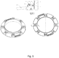
- Figure 1 schematically illustrates a speed ring according to an exemplary embodiment of the present disclosure.
- Figure 1 schematically illustrates a support ring 1 for mounting of a soft box on a light source.
- the support ring 1 comprises attachment means 2 for attachment of the support ring 1 to the light source.
- the support ring comprises at least one cavity 3 configured to receive support pins 4 of the soft box.
- the cavity 3 further comprises a first 5 and a second 6 support element arranged to counteract a torque from the support pins, when the support pins are in an inserted position in the cavity; and at least one entry element 7 arranged on a radial outside of the cavity 3 and arranged to counteract a force required to bend the support pin to an angle where the support pin can be inserted into the cavity 3.
- the at least one cavity 3 can also be a space 3 that among others is narrowed by the first 5 and the second 6 support elements.
- the support ring 1 By providing the support ring 1 with at least one entry element 7 arranged on a radial outside of the cavity 3 and arranged to counteract a force required to bend the support pin to an angle where the support pin can be inserted into the cavity 3, it becomes much easier to insert the support pin 4 into the cavity 3 since the entry element 7 can counter the force from the support pin 4 when the support pin 4 is bent. Thus it is only required to pull the support pin 4 in order to bend the support pin 4 so that the support pin 4 can be inserted into the cavity 3.
- the support ring 1 can be manufactured in many different materials.
- the support ring 1 is made of cast aluminium.
- An advantage with manufacturing the support ring 1 in cast aluminium is that the manufacturing process is easy which means that the support ring 1 can be produced at a low cost.
- Another advantage by manufacturing the support ring 1 in aluminium is that the support ring 1 becomes strong and light weight.
- the cavity 3 in the support ring 1 may be embodied in many different ways. It is however important that the cavity has at least the first 5 and the second 6 support element arranged to counteract a torque from the support pins 4, when the support pins 4 are in an inserted position in the cavity 3.
- the first 5 and the second 6 support elements are inner wall sections of the cylinder 3.
- the cross section of the cavity 3 perpendicular to the radial direction is rectangular or quadratic.
- the dimension of the cross section is adapted to fit the diameter of the support pins 4.
- the first 5 and the second 6 support elements can be interval sections of the quadratic cavity 3.
- first 5 and the second 6 support elements are bar elements perpendicular to a radial direction of the cavity 3.
- the first 5 and the second 6 support elements can be bar elements perpendicular to a radial direction of the cavity 3 in exemplary embodiments were the cavity 3 has different shape.
- the cavity 3 does not have to be a closed space.
- An advantage with the cavity 3 not being a closed space is that the weight of the support ring 1 can be reduced.
- first 5 and the second 6 support elements are bar elements 5, 6, the cross section of the cavity is rectangular or quadratic. In another exemplary embodiment were the first 5 and the second 6 support elements are the bar elements 5, 6 the cross section of the cavity is cylinder shaped.
- the at least one entry element 7 may be embodied in many different ways.
- the at least one entry element 7 is an outer edge of the cavity 3.
- An advantage with this embodiment is that it is not necessary to bend the support pin as much before the outer edge 7 can counteract the force, since the outer edge 7 is positioned further away from the centre of the support ring than the other edge of the cavity.
- the outer edge of the cavity can be embodied in many different ways. It is however important that the outer edge can counteract a force required bending the support pin to an angle where the support pin can be inserted into the cavity 3.
- the at least one entry element 7 is an element arranged at the radial outer opening of the cavity 3.
- This element can be embodied in many different ways. It is however important that the element can counteract a force required bending the support pin to an angle where the support pin can be inserted into the cavity 3.
- the present disclosure also relates to a method for manufacturing a support ring 1 for mounting of a soft box on a light source.
- the method comprises a first step of providing the support ring 1 with attachment means 2 for attachment of the light source on the support ring 1.
- the support ring 1 is provided with at least one cavity 3 configured to receive support pins 4 of the soft box.
- the cavity 3 is provided with a first 5 and a second 6 support element arranged to counteract a torque from the support pins, when the support pins are in an inserted position in the cavity 3.
- the cavity 3 is provided with at least one entry element 7 arranged on a radial outside of the cavity 3 and arranged to counteract a force required to bend the support pin to an angle where the support pin can be inserted into the cavity 3.
- the method of manufacturing the speed ring 1 comprises manufacturing the speed ring wherein the cavity 3 is cylinder shaped and wherein the diameter of the cylinder is adapted to the diameter of the support pins 4.
- the speed ring can be manufactured so that the first 5 and the second 6 support elements are inner wall sections of the cylinder.
- a cross section of the cavity 3 perpendicular to the radial direction is rectangular or quadratic and the dimension of the radial intersection is adapted to fit the diameter of the support pins 4.
- the first 5 and the second 6 support elements are inner wall sections of the rectangular or quadratic cavity 3.
- the first 5 and the second 6 support elements are bar elements perpendicular to a radial direction of the cavity 3.
- the at least one entry element 7 is an outer edge of the cavity 3. In another embodiment of the method the at least one entry element 7 is an element arranged at the radial outer opening of the cavity 3.
- the steps can occur in another order than the order described.
- two method steps shown in succession can in fact be executed substantially concurrently or the method steps can sometimes be executed in the reverse order, depending upon the manufacturing method.
- the speed ring 1 is made of cast aluminium, the method steps are executed substantially concurrently.
Landscapes
- Engineering & Computer Science (AREA)
- General Engineering & Computer Science (AREA)
- Physics & Mathematics (AREA)
- General Physics & Mathematics (AREA)
- Mechanical Engineering (AREA)
- Non-Portable Lighting Devices Or Systems Thereof (AREA)
- Fastening Of Light Sources Or Lamp Holders (AREA)
Description
- The present disclosure relates to a support ring for mounting of a soft box on a light source. The disclosure also relates to a method for manufacturing a support ring for mounting of a soft box on a light source.
- A soft box is a type of photographic lighting device. A soft box creates an even and diffused light by directing light through some diffusing material, or by "bouncing" light off a second surface to diffuse the light. One type of bouncing source is an umbrella light where the light from the bulb is bounced off the inside of a metalized umbrella to create a soft indirect light.
- One type of soft box is an enclosure around a light source comprising reflective side and back walls and a diffusing material at the front of the light.
- The sides and back of the soft box are lined with a bright surface - an aluminized fabric surface or an aluminium foil, to act as an efficient reflector. A speed ring is a solid metal ring-shaped disk which is used to attach a soft box to a light source such as a studio strobe or a continuous light source. Often there are between 4 to 8 holes drilled into the circumference of the ring. These holes receive the support pins of the soft box. Support pins are then held in place in the holes by tension. The shape of the speed ring can vary depending on the manufacturer.
- Typically the opening in the centre ranges from 4 to 7 inches, allowing the light source to enter the soft box or other light modifier.
- Soft boxes, especially large soft boxes require a lot of manual effort during installation. The support pins must be manually bent and angled perpendicular to the centre axis of the speed ring in order to be able to be inserted in the hole of the speed ring. The force required increases with the number of metal ribs which have to be fitted.
- Today there are prior art solutions where the metal ribs are brought into articulated sleeves. In these solutions it is much easier to turn up every metal rib, supported by the articulated sleeves. However, these solutions are expensive and complicated to manufacture since they consists of many parts.
- There is therefore a need for an improved solution for mounting of a soft box on a light source, which solution solves or at least mitigates at least one of the above mentioned problems.
- It is an object of the present disclosure to provide embodiments reducing the amount of manual effort required to mount a soft box on a light source.
- A concept involves providing a speed ring with an entry element arranged on a radial outside and arranged to counteract a force required to bend the support pin to an angle where the support pin can be inserted into the speed ring.
- The disclosure presents a support ring for mounting of a soft box on a light source. The support ring comprises attachment means for attachment of the support ring to the light source, at least one cavity configured to receive support pins of the soft box. The cavity further comprises a first and a second support element arranged to counteract a torque from the support pins, when the support pins are in an inserted position in the cavity, and at least one entry element arranged on a radial outside of the cavity and arranged to counteract a force required to bend the support pin to an angle where the support pin can be inserted into the cavity.
- By providing the support ring with at least one entry element arranged on a radial outside of the cavity and arranged to counteract a force required to bend the support pin to an angle where the support pin can be inserted into the cavity, it becomes much easier to insert the support pin into the cavity since the entry element can counter force the support pin when the support pin is bent. Thus it is only required to pull the support pin in order to bend the support pin so that the support pin can be inserted into the cavity.
- The present disclosure also relates to embodiments of a method for manufacturing a support ring for mounting of a soft box on a light source. The method comprises providing the support ring with attachment means for attachment of the light source on the support ring. Providing the support ring with at least one cavity configured to receive support pins of the soft box. Providing the cavity with a first and a second support element arranged to counteract a torque from the support pins, when the support pins are in an inserted position in the cavity. And providing the cavity with at least one entry element arranged on a radial outside of the cavity and arranged to counteract a force required to bend the support pin to an angle where the support pin can be inserted into the cavity.
- Further objects, features, and advantages of the present disclosure will appear from the following detailed description, wherein some aspects of the disclosure will be described in more detail with reference to the accompanying drawings, in which:
Figure 1 schematically illustrates a speed ring according to an exemplary embodiment of the present disclosure. - Aspects of the present disclosure will be described more fully hereinafter with reference to the accompanying drawings. The devices and methods disclosed herein can, however, be realized in many different forms and should not be construed as being limited to the aspects set forth herein. Like numbers in the drawings refer to like elements throughout.
- The general object or idea of embodiments of the present disclosure is to address at least one or some of the disadvantages with the prior art solutions described above as well as below. The various aspects described below in connection with the figures should be primarily understood in a logical sense.
- The terminology used herein is for the purpose of describing particular aspects of the disclosure only, and is not intended to limit the disclosure to any particular embodiment. As used herein, the singular forms "a", "an" and "the" are intended to include the plural forms as well, unless the context clearly indicates otherwise.
-
Figure 1 schematically illustrates asupport ring 1 for mounting of a soft box on a light source. Thesupport ring 1 comprises attachment means 2 for attachment of thesupport ring 1 to the light source. Further the support ring comprises at least one cavity 3 configured to receive support pins 4 of the soft box. According to an aspect of the present disclosure the cavity 3 further comprises a first 5 and a second 6 support element arranged to counteract a torque from the support pins, when the support pins are in an inserted position in the cavity; and at least one entry element 7 arranged on a radial outside of the cavity 3 and arranged to counteract a force required to bend the support pin to an angle where the support pin can be inserted into the cavity 3. The at least one cavity 3 can also be a space 3 that among others is narrowed by the first 5 and the second 6 support elements. - By providing the
support ring 1 with at least one entry element 7 arranged on a radial outside of the cavity 3 and arranged to counteract a force required to bend the support pin to an angle where the support pin can be inserted into the cavity 3, it becomes much easier to insert the support pin 4 into the cavity 3 since the entry element 7 can counter the force from the support pin 4 when the support pin 4 is bent. Thus it is only required to pull the support pin 4 in order to bend the support pin 4 so that the support pin 4 can be inserted into the cavity 3. - The
support ring 1 can be manufactured in many different materials. Preferably thesupport ring 1 is made of cast aluminium. An advantage with manufacturing thesupport ring 1 in cast aluminium is that the manufacturing process is easy which means that thesupport ring 1 can be produced at a low cost. Another advantage by manufacturing thesupport ring 1 in aluminium is that thesupport ring 1 becomes strong and light weight. - The cavity 3 in the
support ring 1 may be embodied in many different ways. It is however important that the cavity has at least the first 5 and the second 6 support element arranged to counteract a torque from the support pins 4, when the support pins 4 are in an inserted position in the cavity 3. According to one aspect of the present disclosure is the cavity 3 cylinder shaped and has a diameter that is adapted to the diameter of the support pins 4. - According to one aspect of the present disclosure, in an embodiment where the cavity 3 is cylinder shaped, the first 5 and the second 6 support elements are inner wall sections of the cylinder 3.
- According to another aspect of the present disclosure the cross section of the cavity 3 perpendicular to the radial direction is rectangular or quadratic. In this embodiment the dimension of the cross section is adapted to fit the diameter of the support pins 4.
- In the exemplary embodiment of the present disclosure where the cross section of the cavity 3 perpendicular to the radial direction is rectangular or quadratic the first 5 and the second 6 support elements can be interval sections of the quadratic cavity 3.
- According to another aspect of the present disclosure the first 5 and the second 6 support elements are bar elements perpendicular to a radial direction of the cavity 3. The first 5 and the second 6 support elements can be bar elements perpendicular to a radial direction of the cavity 3 in exemplary embodiments were the cavity 3 has different shape.
- The cavity 3 does not have to be a closed space. An advantage with the cavity 3 not being a closed space is that the weight of the
support ring 1 can be reduced. - In one exemplary embodiment were the first 5 and the second 6 support elements are bar elements 5, 6, the cross section of the cavity is rectangular or quadratic. In another exemplary embodiment were the first 5 and the second 6 support elements are the bar elements 5, 6 the cross section of the cavity is cylinder shaped.
- The at least one entry element 7 may be embodied in many different ways. According to one aspect of the present disclosure the at least one entry element 7 is an outer edge of the cavity 3. An advantage with this embodiment is that it is not necessary to bend the support pin as much before the outer edge 7 can counteract the force, since the outer edge 7 is positioned further away from the centre of the support ring than the other edge of the cavity. The outer edge of the cavity can be embodied in many different ways. It is however important that the outer edge can counteract a force required bending the support pin to an angle where the support pin can be inserted into the cavity 3.
- According to another aspect of the present disclosure the at least one entry element 7 is an element arranged at the radial outer opening of the cavity 3. This element can be embodied in many different ways. It is however important that the element can counteract a force required bending the support pin to an angle where the support pin can be inserted into the cavity 3.
- The present disclosure also relates to a method for manufacturing a
support ring 1 for mounting of a soft box on a light source. The method comprises a first step of providing thesupport ring 1 with attachment means 2 for attachment of the light source on thesupport ring 1. In a next step thesupport ring 1 is provided with at least one cavity 3 configured to receive support pins 4 of the soft box. Thereafter in yet another step the cavity 3 is provided with a first 5 and a second 6 support element arranged to counteract a torque from the support pins, when the support pins are in an inserted position in the cavity 3. Next, the cavity 3 is provided with at least one entry element 7 arranged on a radial outside of the cavity 3 and arranged to counteract a force required to bend the support pin to an angle where the support pin can be inserted into the cavity 3. - According to one aspect of the present disclosure the method of manufacturing the
speed ring 1 comprises manufacturing the speed ring wherein the cavity 3 is cylinder shaped and wherein the diameter of the cylinder is adapted to the diameter of the support pins 4. - The speed ring can be manufactured so that the first 5 and the second 6 support elements are inner wall sections of the cylinder.
- According to another aspect of the manufacturing method a cross section of the cavity 3 perpendicular to the radial direction is rectangular or quadratic and the dimension of the radial intersection is adapted to fit the diameter of the support pins 4.
- Further in the method of manufacturing the speed ring, the first 5 and the second 6 support elements are inner wall sections of the rectangular or quadratic cavity 3. In another exemplary embodiment the first 5 and the second 6 support elements are bar elements perpendicular to a radial direction of the cavity 3.
- According to one aspect of the manufacturing method the at least one entry element 7 is an outer edge of the cavity 3. In another embodiment of the method the at least one entry element 7 is an element arranged at the radial outer opening of the cavity 3.
- In some implementations and according to some aspects of the disclosure of the method for manufacturing, the steps can occur in another order than the order described. For example, two method steps shown in succession can in fact be executed substantially concurrently or the method steps can sometimes be executed in the reverse order, depending upon the manufacturing method. Especially if the
speed ring 1 is made of cast aluminium, the method steps are executed substantially concurrently. - In the drawings and specification, there have been disclosed exemplary aspects of the disclosure. However, many variations and modifications can be made to these aspects without substantially departing from the principles of the present disclosure. Thus, the disclosure should be regarded as illustrative rather than restrictive, and not as being limited to the particular aspects discussed above. Accordingly, although specific terms are employed, they are used in a generic and descriptive sense only and not for purposes of limitation.
Claims (16)
- A support ring (1) for mounting of a soft box on a light source, the support ring (1) comprising:attachment means (2) for attachment of the support ring (1) to the light source;at least one cavity (3) configured to receive support pins (4) of the soft box, characterized in that the cavity (3) further comprisinga first (5) and a second (6) support element arranged to counteract a torque from the support pins, when the support pins are in an inserted position in the cavity; andat least one entry element (7) arranged on a radial outside of the cavity (3) and arranged to counteract a force required to bend the support pin to an angle where the support pin can be inserted into the cavity (3).
- The support ring (1) according to claim 1, wherein the cavity (3) is cylinder shaped and wherein the diameter of the cylinder is adapted to the diameter of the support pins (4).
- The support ring (1) according to claim 2, wherein the first (5) and the second (6) support elements are inner wall sections of the cylinder.
- The support ring (1) according to claim 1, wherein a cross section of the cavity (3) perpendicular to the radial direction is rectangular or quadratic and wherein the dimension of the cross section is adapted to fit the diameter of the support pins (4).
- The support ring (1) according to claim 4, wherein the first (5) and the second (6) support elements are interval sections of the rectangular or quadratic cavity (3).
- The support ring (1) according to anyone of claims 1 and 4, wherein the first (5) and the second (6) support elements are bar elements perpendicular to a radial direction of the cavity (3).
- The support ring (1) according to any of claims 1 to 6, wherein the at least one entry element (7) is outer edge of the cavity (3).
- The support ring (1) according to any of claims 1 to 6, wherein the at least one entry element (7) comprising an element arranged at the radial outer opening of the cavity (3).
- A method for manufacturing a support ring (1) for mounting of a soft box on a light source, the method comprising:providing the support ring (1) with attachment means (2) for attachment of the light source on the support ring (1);providing the support ring (1) with at least one cavity (3) configured to receive support pins (4) of the soft box;providing the cavity (3) with a first (5) and a second (6) support element arranged to counteract a torque from the support pins, when the support pins are in an inserted position in the cavity; andproviding the cavity (3) with at least one entry element (7) arranged on a radial outside of the cavity (3) and arranged to counteract a force required to bend the support pin to an angle where the support pin can be inserted into the cavity (3).
- The method according to claim 9, wherein the cavity (3) is cylinder shaped and wherein the diameter of the cylinder is adapted to the diameter of the support pins (4).
- The method according to claim 10, wherein the first (5) and the second (6) support elements are inner wall sections of the cylinder.
- The method according to claim 9, wherein a cross section of the cavity (3) perpendicular to the radial direction is rectangular or quadratic and wherein the dimension of the radial intersection is adapted to fit the diameter of the support pins (4).
- The method according to claim 12, wherein the first (5) and the second (6) support elements are inner wall sections of the rectangular or quadratic cavity (3).
- The method according to claims 9 and 12, wherein the first (5) and the second (6) support elements are bar elements perpendicular to a radial direction of the cavity (3).
- The method according to any of claims 9 to 14, wherein the at least one entry element (7) is outer edge of the cavity (3).
- The method according to any of claims 9 to 15, wherein the at least one entry element (7) comprising an element arranged at the radial outer opening of the cavity (3).
Applications Claiming Priority (2)
| Application Number | Priority Date | Filing Date | Title |
|---|---|---|---|
| SE1451392 | 2014-11-19 | ||
| PCT/SE2015/051140 WO2016080885A1 (en) | 2014-11-19 | 2015-10-28 | A support ring for mounting of a soft box on a light source |
Publications (3)
| Publication Number | Publication Date |
|---|---|
| EP3221745A1 EP3221745A1 (en) | 2017-09-27 |
| EP3221745A4 EP3221745A4 (en) | 2019-06-12 |
| EP3221745B1 true EP3221745B1 (en) | 2020-08-12 |
Family
ID=56014282
Family Applications (1)
| Application Number | Title | Priority Date | Filing Date |
|---|---|---|---|
| EP15860087.4A Active EP3221745B1 (en) | 2014-11-19 | 2015-10-28 | A support ring for mounting of a soft box on a light source |
Country Status (4)
| Country | Link |
|---|---|
| US (1) | US10197250B2 (en) |
| EP (1) | EP3221745B1 (en) |
| CN (1) | CN107003590B (en) |
| WO (1) | WO2016080885A1 (en) |
Family Cites Families (15)
| Publication number | Priority date | Publication date | Assignee | Title |
|---|---|---|---|---|
| US2948287A (en) | 1957-09-30 | 1960-08-09 | Charles W Moss | Quickly-erectable folding portable shelter |
| DE19910469A1 (en) * | 1999-03-10 | 2000-09-21 | Wila Leuchten Ag Sevelen | Luminaire arrangement |
| US6651682B1 (en) * | 2001-08-03 | 2003-11-25 | James Woodward | Rugged assemable, disassemable and storable umbrella |
| CN2621307Y (en) * | 2002-09-13 | 2004-06-23 | 广东普思贸易有限公司 | Subdued light box connecting mouth |
| US7077534B2 (en) * | 2004-04-02 | 2006-07-18 | Calumet Photographic Inc. | Soft box assembly and pole support assembly therefor |
| CN200956080Y (en) * | 2006-10-12 | 2007-10-03 | 深圳市元科摄影器材有限公司 | Softbox adapter |
| CN200969013Y (en) * | 2006-11-14 | 2007-10-31 | 何济仪 | A constant-bright photographic light with a soft box |
| US20070217772A1 (en) * | 2006-11-28 | 2007-09-20 | Lemelson Greg M | Integrated light head apparatus and methods of use thereof |
| US7416316B2 (en) * | 2006-12-06 | 2008-08-26 | Lowel-Light Manufacturing, Inc. | Strut holding assembly |
| US8157226B2 (en) * | 2008-09-23 | 2012-04-17 | Paul Kent Peregrine | Mounting system for attaching multiple light sources for photographic use |
| US8684569B2 (en) * | 2011-07-06 | 2014-04-01 | Cree, Inc. | Lens and trim attachment structure for solid state downlights |
| KR101127458B1 (en) * | 2011-10-20 | 2012-03-22 | 김종석 | Foldable soft box |
| TW201411035A (en) * | 2012-09-14 | 2014-03-16 | Taiwan Fu Hsing Ind Co Ltd | Mounting structure for lamp device |
| US20140153277A1 (en) * | 2012-11-30 | 2014-06-05 | Liang Meng Plastic Share Co., Ltd. | Assembling structure for led lamp module |
| KR101478673B1 (en) * | 2013-04-04 | 2015-01-02 | 김종석 | soft box type illumination apparatus for wireless control |
-
2015
- 2015-10-28 EP EP15860087.4A patent/EP3221745B1/en active Active
- 2015-10-28 WO PCT/SE2015/051140 patent/WO2016080885A1/en not_active Ceased
- 2015-10-28 US US15/525,542 patent/US10197250B2/en active Active
- 2015-10-28 CN CN201580060655.0A patent/CN107003590B/en active Active
Non-Patent Citations (1)
| Title |
|---|
| None * |
Also Published As
| Publication number | Publication date |
|---|---|
| US20170314767A1 (en) | 2017-11-02 |
| US10197250B2 (en) | 2019-02-05 |
| EP3221745A1 (en) | 2017-09-27 |
| CN107003590B (en) | 2019-10-01 |
| CN107003590A (en) | 2017-08-01 |
| WO2016080885A1 (en) | 2016-05-26 |
| EP3221745A4 (en) | 2019-06-12 |
Similar Documents
| Publication | Publication Date | Title |
|---|---|---|
| JP2017020648A (en) | Attachment device for attaching equipment, attachment method, and removal method | |
| US10520169B2 (en) | Snap in retrofit panel | |
| EP3418621B1 (en) | Lighting device and method for manufacturing a lighting device | |
| US10197250B2 (en) | Support ring for mounting of a soft box on a light source | |
| EP2902260A3 (en) | Open roof construction for a vehicle and rollo assembly therefor | |
| US20150148183A1 (en) | Planetary gearset | |
| RU195863U1 (en) | DEVICE FOR INSTALLATION OF AUXILIARY EQUIPMENT IN A STRETCH CEILING | |
| CN201666550U (en) | Combining-connecting device for ceiling downlight and ceiling panel | |
| ITTO980102A1 (en) | MOTOR VEHICLE PROJECTOR | |
| US9239162B2 (en) | Liner for preventing airflow through a recessed light and a method for installing the liner | |
| US20080137352A1 (en) | Strut holding assembly | |
| CN103185308B (en) | Lamp fixing device and there is the light fixture of described lamp fixing device | |
| CN108957908B (en) | Double-adjusting aperture | |
| BR112017009874A2 (en) | vehicle door mirror | |
| US20080083513A1 (en) | Dual-purpose fixing core for a blind | |
| CN104896073A (en) | Speed reducer | |
| RU139023U1 (en) | LIGHT MOUNTING DEVICE (OPTIONS) | |
| US3476925A (en) | Floodlight reflector assembly | |
| JP7003557B2 (en) | lighting equipment | |
| KR200450149Y1 (en) | Lamp holder for downlight with rotation and angle adjustment | |
| CN205174256U (en) | Lamp | |
| JP6799749B2 (en) | Ventilation hood | |
| CN100510566C (en) | Method for forming mounting tab of air diffuser body and mounting tab of air diffuser body | |
| CN204899735U (en) | Assembled roll of curtain rail is said and (window) curtain | |
| CN204403939U (en) | Novel logo projection lamp |
Legal Events
| Date | Code | Title | Description |
|---|---|---|---|
| STAA | Information on the status of an ep patent application or granted ep patent |
Free format text: STATUS: THE INTERNATIONAL PUBLICATION HAS BEEN MADE |
|
| PUAI | Public reference made under article 153(3) epc to a published international application that has entered the european phase |
Free format text: ORIGINAL CODE: 0009012 |
|
| STAA | Information on the status of an ep patent application or granted ep patent |
Free format text: STATUS: REQUEST FOR EXAMINATION WAS MADE |
|
| 17P | Request for examination filed |
Effective date: 20170612 |
|
| AK | Designated contracting states |
Kind code of ref document: A1 Designated state(s): AL AT BE BG CH CY CZ DE DK EE ES FI FR GB GR HR HU IE IS IT LI LT LU LV MC MK MT NL NO PL PT RO RS SE SI SK SM TR |
|
| AX | Request for extension of the european patent |
Extension state: BA ME |
|
| DAV | Request for validation of the european patent (deleted) | ||
| DAX | Request for extension of the european patent (deleted) | ||
| A4 | Supplementary search report drawn up and despatched |
Effective date: 20190515 |
|
| RIC1 | Information provided on ipc code assigned before grant |
Ipc: F21V 7/18 20060101ALI20190509BHEP Ipc: F21V 17/04 20060101ALI20190509BHEP Ipc: F21V 1/06 20060101ALI20190509BHEP Ipc: G03B 15/02 20060101AFI20190509BHEP |
|
| REG | Reference to a national code |
Ref country code: DE Ref legal event code: R079 Ref document number: 602015057506 Country of ref document: DE Free format text: PREVIOUS MAIN CLASS: G03B0015020000 Ipc: G03B0015060000 |
|
| RIC1 | Information provided on ipc code assigned before grant |
Ipc: G03B 15/06 20060101AFI20200224BHEP |
|
| GRAP | Despatch of communication of intention to grant a patent |
Free format text: ORIGINAL CODE: EPIDOSNIGR1 |
|
| STAA | Information on the status of an ep patent application or granted ep patent |
Free format text: STATUS: GRANT OF PATENT IS INTENDED |
|
| INTG | Intention to grant announced |
Effective date: 20200504 |
|
| GRAS | Grant fee paid |
Free format text: ORIGINAL CODE: EPIDOSNIGR3 |
|
| GRAA | (expected) grant |
Free format text: ORIGINAL CODE: 0009210 |
|
| STAA | Information on the status of an ep patent application or granted ep patent |
Free format text: STATUS: THE PATENT HAS BEEN GRANTED |
|
| AK | Designated contracting states |
Kind code of ref document: B1 Designated state(s): AL AT BE BG CH CY CZ DE DK EE ES FI FR GB GR HR HU IE IS IT LI LT LU LV MC MK MT NL NO PL PT RO RS SE SI SK SM TR |
|
| REG | Reference to a national code |
Ref country code: CH Ref legal event code: EP |
|
| REG | Reference to a national code |
Ref country code: DE Ref legal event code: R096 Ref document number: 602015057506 Country of ref document: DE |
|
| REG | Reference to a national code |
Ref country code: IE Ref legal event code: FG4D |
|
| REG | Reference to a national code |
Ref country code: AT Ref legal event code: REF Ref document number: 1302143 Country of ref document: AT Kind code of ref document: T Effective date: 20200915 |
|
| REG | Reference to a national code |
Ref country code: LT Ref legal event code: MG4D |
|
| REG | Reference to a national code |
Ref country code: NL Ref legal event code: MP Effective date: 20200812 |
|
| PG25 | Lapsed in a contracting state [announced via postgrant information from national office to epo] |
Ref country code: SE Free format text: LAPSE BECAUSE OF FAILURE TO SUBMIT A TRANSLATION OF THE DESCRIPTION OR TO PAY THE FEE WITHIN THE PRESCRIBED TIME-LIMIT Effective date: 20200812 Ref country code: BG Free format text: LAPSE BECAUSE OF FAILURE TO SUBMIT A TRANSLATION OF THE DESCRIPTION OR TO PAY THE FEE WITHIN THE PRESCRIBED TIME-LIMIT Effective date: 20201112 Ref country code: HR Free format text: LAPSE BECAUSE OF FAILURE TO SUBMIT A TRANSLATION OF THE DESCRIPTION OR TO PAY THE FEE WITHIN THE PRESCRIBED TIME-LIMIT Effective date: 20200812 Ref country code: LT Free format text: LAPSE BECAUSE OF FAILURE TO SUBMIT A TRANSLATION OF THE DESCRIPTION OR TO PAY THE FEE WITHIN THE PRESCRIBED TIME-LIMIT Effective date: 20200812 Ref country code: NO Free format text: LAPSE BECAUSE OF FAILURE TO SUBMIT A TRANSLATION OF THE DESCRIPTION OR TO PAY THE FEE WITHIN THE PRESCRIBED TIME-LIMIT Effective date: 20201112 Ref country code: GR Free format text: LAPSE BECAUSE OF FAILURE TO SUBMIT A TRANSLATION OF THE DESCRIPTION OR TO PAY THE FEE WITHIN THE PRESCRIBED TIME-LIMIT Effective date: 20201113 Ref country code: FI Free format text: LAPSE BECAUSE OF FAILURE TO SUBMIT A TRANSLATION OF THE DESCRIPTION OR TO PAY THE FEE WITHIN THE PRESCRIBED TIME-LIMIT Effective date: 20200812 |
|
| REG | Reference to a national code |
Ref country code: AT Ref legal event code: MK05 Ref document number: 1302143 Country of ref document: AT Kind code of ref document: T Effective date: 20200812 |
|
| PG25 | Lapsed in a contracting state [announced via postgrant information from national office to epo] |
Ref country code: LV Free format text: LAPSE BECAUSE OF FAILURE TO SUBMIT A TRANSLATION OF THE DESCRIPTION OR TO PAY THE FEE WITHIN THE PRESCRIBED TIME-LIMIT Effective date: 20200812 Ref country code: NL Free format text: LAPSE BECAUSE OF FAILURE TO SUBMIT A TRANSLATION OF THE DESCRIPTION OR TO PAY THE FEE WITHIN THE PRESCRIBED TIME-LIMIT Effective date: 20200812 Ref country code: RS Free format text: LAPSE BECAUSE OF FAILURE TO SUBMIT A TRANSLATION OF THE DESCRIPTION OR TO PAY THE FEE WITHIN THE PRESCRIBED TIME-LIMIT Effective date: 20200812 Ref country code: PL Free format text: LAPSE BECAUSE OF FAILURE TO SUBMIT A TRANSLATION OF THE DESCRIPTION OR TO PAY THE FEE WITHIN THE PRESCRIBED TIME-LIMIT Effective date: 20200812 Ref country code: IS Free format text: LAPSE BECAUSE OF FAILURE TO SUBMIT A TRANSLATION OF THE DESCRIPTION OR TO PAY THE FEE WITHIN THE PRESCRIBED TIME-LIMIT Effective date: 20201212 |
|
| PG25 | Lapsed in a contracting state [announced via postgrant information from national office to epo] |
Ref country code: DK Free format text: LAPSE BECAUSE OF FAILURE TO SUBMIT A TRANSLATION OF THE DESCRIPTION OR TO PAY THE FEE WITHIN THE PRESCRIBED TIME-LIMIT Effective date: 20200812 Ref country code: CZ Free format text: LAPSE BECAUSE OF FAILURE TO SUBMIT A TRANSLATION OF THE DESCRIPTION OR TO PAY THE FEE WITHIN THE PRESCRIBED TIME-LIMIT Effective date: 20200812 Ref country code: EE Free format text: LAPSE BECAUSE OF FAILURE TO SUBMIT A TRANSLATION OF THE DESCRIPTION OR TO PAY THE FEE WITHIN THE PRESCRIBED TIME-LIMIT Effective date: 20200812 Ref country code: SM Free format text: LAPSE BECAUSE OF FAILURE TO SUBMIT A TRANSLATION OF THE DESCRIPTION OR TO PAY THE FEE WITHIN THE PRESCRIBED TIME-LIMIT Effective date: 20200812 Ref country code: RO Free format text: LAPSE BECAUSE OF FAILURE TO SUBMIT A TRANSLATION OF THE DESCRIPTION OR TO PAY THE FEE WITHIN THE PRESCRIBED TIME-LIMIT Effective date: 20200812 |
|
| REG | Reference to a national code |
Ref country code: DE Ref legal event code: R097 Ref document number: 602015057506 Country of ref document: DE |
|
| PG25 | Lapsed in a contracting state [announced via postgrant information from national office to epo] |
Ref country code: ES Free format text: LAPSE BECAUSE OF FAILURE TO SUBMIT A TRANSLATION OF THE DESCRIPTION OR TO PAY THE FEE WITHIN THE PRESCRIBED TIME-LIMIT Effective date: 20200812 Ref country code: AL Free format text: LAPSE BECAUSE OF FAILURE TO SUBMIT A TRANSLATION OF THE DESCRIPTION OR TO PAY THE FEE WITHIN THE PRESCRIBED TIME-LIMIT Effective date: 20200812 Ref country code: AT Free format text: LAPSE BECAUSE OF FAILURE TO SUBMIT A TRANSLATION OF THE DESCRIPTION OR TO PAY THE FEE WITHIN THE PRESCRIBED TIME-LIMIT Effective date: 20200812 |
|
| REG | Reference to a national code |
Ref country code: CH Ref legal event code: PL |
|
| PLBE | No opposition filed within time limit |
Free format text: ORIGINAL CODE: 0009261 |
|
| STAA | Information on the status of an ep patent application or granted ep patent |
Free format text: STATUS: NO OPPOSITION FILED WITHIN TIME LIMIT |
|
| PG25 | Lapsed in a contracting state [announced via postgrant information from national office to epo] |
Ref country code: MC Free format text: LAPSE BECAUSE OF FAILURE TO SUBMIT A TRANSLATION OF THE DESCRIPTION OR TO PAY THE FEE WITHIN THE PRESCRIBED TIME-LIMIT Effective date: 20200812 Ref country code: SK Free format text: LAPSE BECAUSE OF FAILURE TO SUBMIT A TRANSLATION OF THE DESCRIPTION OR TO PAY THE FEE WITHIN THE PRESCRIBED TIME-LIMIT Effective date: 20200812 Ref country code: LU Free format text: LAPSE BECAUSE OF NON-PAYMENT OF DUE FEES Effective date: 20201028 |
|
| REG | Reference to a national code |
Ref country code: BE Ref legal event code: MM Effective date: 20201031 |
|
| 26N | No opposition filed |
Effective date: 20210514 |
|
| GBPC | Gb: european patent ceased through non-payment of renewal fee |
Effective date: 20201112 |
|
| PG25 | Lapsed in a contracting state [announced via postgrant information from national office to epo] |
Ref country code: FR Free format text: LAPSE BECAUSE OF NON-PAYMENT OF DUE FEES Effective date: 20201031 Ref country code: IT Free format text: LAPSE BECAUSE OF FAILURE TO SUBMIT A TRANSLATION OF THE DESCRIPTION OR TO PAY THE FEE WITHIN THE PRESCRIBED TIME-LIMIT Effective date: 20200812 |
|
| PG25 | Lapsed in a contracting state [announced via postgrant information from national office to epo] |
Ref country code: BE Free format text: LAPSE BECAUSE OF NON-PAYMENT OF DUE FEES Effective date: 20201031 Ref country code: CH Free format text: LAPSE BECAUSE OF NON-PAYMENT OF DUE FEES Effective date: 20201031 Ref country code: LI Free format text: LAPSE BECAUSE OF NON-PAYMENT OF DUE FEES Effective date: 20201031 Ref country code: SI Free format text: LAPSE BECAUSE OF FAILURE TO SUBMIT A TRANSLATION OF THE DESCRIPTION OR TO PAY THE FEE WITHIN THE PRESCRIBED TIME-LIMIT Effective date: 20200812 |
|
| PG25 | Lapsed in a contracting state [announced via postgrant information from national office to epo] |
Ref country code: IE Free format text: LAPSE BECAUSE OF NON-PAYMENT OF DUE FEES Effective date: 20201028 |
|
| PG25 | Lapsed in a contracting state [announced via postgrant information from national office to epo] |
Ref country code: GB Free format text: LAPSE BECAUSE OF NON-PAYMENT OF DUE FEES Effective date: 20201112 |
|
| PG25 | Lapsed in a contracting state [announced via postgrant information from national office to epo] |
Ref country code: IS Free format text: LAPSE BECAUSE OF FAILURE TO SUBMIT A TRANSLATION OF THE DESCRIPTION OR TO PAY THE FEE WITHIN THE PRESCRIBED TIME-LIMIT Effective date: 20201212 Ref country code: TR Free format text: LAPSE BECAUSE OF FAILURE TO SUBMIT A TRANSLATION OF THE DESCRIPTION OR TO PAY THE FEE WITHIN THE PRESCRIBED TIME-LIMIT Effective date: 20200812 Ref country code: MT Free format text: LAPSE BECAUSE OF FAILURE TO SUBMIT A TRANSLATION OF THE DESCRIPTION OR TO PAY THE FEE WITHIN THE PRESCRIBED TIME-LIMIT Effective date: 20200812 Ref country code: CY Free format text: LAPSE BECAUSE OF FAILURE TO SUBMIT A TRANSLATION OF THE DESCRIPTION OR TO PAY THE FEE WITHIN THE PRESCRIBED TIME-LIMIT Effective date: 20200812 |
|
| PG25 | Lapsed in a contracting state [announced via postgrant information from national office to epo] |
Ref country code: MK Free format text: LAPSE BECAUSE OF FAILURE TO SUBMIT A TRANSLATION OF THE DESCRIPTION OR TO PAY THE FEE WITHIN THE PRESCRIBED TIME-LIMIT Effective date: 20200812 |
|
| PG25 | Lapsed in a contracting state [announced via postgrant information from national office to epo] |
Ref country code: PT Free format text: LAPSE BECAUSE OF FAILURE TO SUBMIT A TRANSLATION OF THE DESCRIPTION OR TO PAY THE FEE WITHIN THE PRESCRIBED TIME-LIMIT Effective date: 20200812 |
|
| P01 | Opt-out of the competence of the unified patent court (upc) registered |
Effective date: 20230524 |
|
| PGFP | Annual fee paid to national office [announced via postgrant information from national office to epo] |
Ref country code: DE Payment date: 20250917 Year of fee payment: 11 |