EP3221667B3 - Induktiver positionsdetektor - Google Patents
Induktiver positionsdetektor Download PDFInfo
- Publication number
- EP3221667B3 EP3221667B3 EP15703624.5A EP15703624A EP3221667B3 EP 3221667 B3 EP3221667 B3 EP 3221667B3 EP 15703624 A EP15703624 A EP 15703624A EP 3221667 B3 EP3221667 B3 EP 3221667B3
- Authority
- EP
- European Patent Office
- Prior art keywords
- winding
- antenna
- position detector
- winding arrangement
- arrangement
- Prior art date
- Legal status (The legal status is an assumption and is not a legal conclusion. Google has not performed a legal analysis and makes no representation as to the accuracy of the status listed.)
- Active
Links
Images


Classifications
-
- G—PHYSICS
- G01—MEASURING; TESTING
- G01D—MEASURING NOT SPECIALLY ADAPTED FOR A SPECIFIC VARIABLE; ARRANGEMENTS FOR MEASURING TWO OR MORE VARIABLES NOT COVERED IN A SINGLE OTHER SUBCLASS; TARIFF METERING APPARATUS; MEASURING OR TESTING NOT OTHERWISE PROVIDED FOR
- G01D5/00—Mechanical means for transferring the output of a sensing member; Means for converting the output of a sensing member to another variable where the form or nature of the sensing member does not constrain the means for converting; Transducers not specially adapted for a specific variable
- G01D5/12—Mechanical means for transferring the output of a sensing member; Means for converting the output of a sensing member to another variable where the form or nature of the sensing member does not constrain the means for converting; Transducers not specially adapted for a specific variable using electric or magnetic means
- G01D5/14—Mechanical means for transferring the output of a sensing member; Means for converting the output of a sensing member to another variable where the form or nature of the sensing member does not constrain the means for converting; Transducers not specially adapted for a specific variable using electric or magnetic means influencing the magnitude of a current or voltage
- G01D5/20—Mechanical means for transferring the output of a sensing member; Means for converting the output of a sensing member to another variable where the form or nature of the sensing member does not constrain the means for converting; Transducers not specially adapted for a specific variable using electric or magnetic means influencing the magnitude of a current or voltage by varying inductance, e.g. by a movable armature
- G01D5/204—Mechanical means for transferring the output of a sensing member; Means for converting the output of a sensing member to another variable where the form or nature of the sensing member does not constrain the means for converting; Transducers not specially adapted for a specific variable using electric or magnetic means influencing the magnitude of a current or voltage by varying inductance, e.g. by a movable armature by influencing the mutual induction between two or more coils
- G01D5/2073—Mechanical means for transferring the output of a sensing member; Means for converting the output of a sensing member to another variable where the form or nature of the sensing member does not constrain the means for converting; Transducers not specially adapted for a specific variable using electric or magnetic means influencing the magnitude of a current or voltage by varying inductance, e.g. by a movable armature by influencing the mutual induction between two or more coils by movement of a single coil with respect to two or more coils
-
- B—PERFORMING OPERATIONS; TRANSPORTING
- B62—LAND VEHICLES FOR TRAVELLING OTHERWISE THAN ON RAILS
- B62D—MOTOR VEHICLES; TRAILERS
- B62D1/00—Steering controls, i.e. means for initiating a change of direction of the vehicle
- B62D1/02—Steering controls, i.e. means for initiating a change of direction of the vehicle vehicle-mounted
- B62D1/16—Steering columns
- B62D1/18—Steering columns yieldable or adjustable, e.g. tiltable
- B62D1/185—Steering columns yieldable or adjustable, e.g. tiltable adjustable by axial displacement, e.g. telescopically
-
- G—PHYSICS
- G01—MEASURING; TESTING
- G01B—MEASURING LENGTH, THICKNESS OR SIMILAR LINEAR DIMENSIONS; MEASURING ANGLES; MEASURING AREAS; MEASURING IRREGULARITIES OF SURFACES OR CONTOURS
- G01B7/00—Measuring arrangements characterised by the use of electric or magnetic techniques
- G01B7/02—Measuring arrangements characterised by the use of electric or magnetic techniques for measuring length, width or thickness
- G01B7/023—Measuring arrangements characterised by the use of electric or magnetic techniques for measuring length, width or thickness for measuring distance between sensor and object
-
- G—PHYSICS
- G01—MEASURING; TESTING
- G01D—MEASURING NOT SPECIALLY ADAPTED FOR A SPECIFIC VARIABLE; ARRANGEMENTS FOR MEASURING TWO OR MORE VARIABLES NOT COVERED IN A SINGLE OTHER SUBCLASS; TARIFF METERING APPARATUS; MEASURING OR TESTING NOT OTHERWISE PROVIDED FOR
- G01D5/00—Mechanical means for transferring the output of a sensing member; Means for converting the output of a sensing member to another variable where the form or nature of the sensing member does not constrain the means for converting; Transducers not specially adapted for a specific variable
- G01D5/12—Mechanical means for transferring the output of a sensing member; Means for converting the output of a sensing member to another variable where the form or nature of the sensing member does not constrain the means for converting; Transducers not specially adapted for a specific variable using electric or magnetic means
- G01D5/14—Mechanical means for transferring the output of a sensing member; Means for converting the output of a sensing member to another variable where the form or nature of the sensing member does not constrain the means for converting; Transducers not specially adapted for a specific variable using electric or magnetic means influencing the magnitude of a current or voltage
- G01D5/20—Mechanical means for transferring the output of a sensing member; Means for converting the output of a sensing member to another variable where the form or nature of the sensing member does not constrain the means for converting; Transducers not specially adapted for a specific variable using electric or magnetic means influencing the magnitude of a current or voltage by varying inductance, e.g. by a movable armature
- G01D5/204—Mechanical means for transferring the output of a sensing member; Means for converting the output of a sensing member to another variable where the form or nature of the sensing member does not constrain the means for converting; Transducers not specially adapted for a specific variable using electric or magnetic means influencing the magnitude of a current or voltage by varying inductance, e.g. by a movable armature by influencing the mutual induction between two or more coils
Definitions
- This invention relates to an inductive displacement or position detector, operable to measure the displacement of relatively moveable bodies.
- Such disturbances or non-linearities come from various sources including manufacturing irregularities in the windings, capacitive coupling between the windings, cross-talk between windings, plated via holes between layers etc.
- Such disturbances are of no consequence for relatively low performance detectors requiring an accuracy of perhaps 1% of full-scale but when accuracies of ⁇ 1% are required then they are highly problematic not least because the imperfections are typically small and numerous, thus making them difficult to eradicate through a simple calibration.
- These small and numerous imperfections or non-linearities typically require calibration with typically >10, often >100 and possibly >1000 correction points along the measurement scale thus making calibration difficult and time consuming.
- WO 2009/053752A2 discloses an inductive detector with first and second target winding arrangements of the same overall length as antenna windings.
- Embodiments of the invention provide an inductive detector with superior measurement performance.
- the invention provides an inductive position detector with a first and a second body which are displaceable relative to one another along a measurement path
- said first body comprises: at least first and second antenna winding arrangements, each of said antenna winding arrangements defining a plurality of adjacent receive winding loops extending in the direction of the measurement path
- said second body comprises: a passive resonant circuit incorporating at least first and second target winding arrangements in series with a capacitor, saidsecond target winding arrangement defining a plurality of adjacent winding loops extending in the direction of the measurement path; said first and second antenna winding arrangements and said first and second target winding arrangements both being spaced apart orthogonally of said measurement path so as to be separate, and said first and second bodies being disposed so that first and second target winding arrangements cover at least a part of first and second antenna winding arrangements respectively; characterised in that
- This configuration is particularly advantageous in preferred embodiments since they allow considerable improvements in the accuracy of the measurement.
- the second antenna winding arrangement of said first body and the second target winding arrangement of said second body vary at substantially the same pitch.
- the antenna winding arrangement of said first body incorporates at least a first series of adjacent receive winding loops and a second series of adjacent receive winding loops which overlap one another and are shifted by 1 ⁇ 4 pitch relative to each other along the measurement path.
- the second antenna winding arrangement of the first body incorporates at least one electrical connection; and the second target winding arrangement of said second body incorporates at least one electrical connection with the first target winding arrangement; said at least one electrical connection of said first body being located in an area which is non-overlapping with the area in which said electrical connection of said second body is provided.
- This configuration further reduces errors or noise that may otherwise arise in embodiments where the electrical connections overlap one another.
- the second antenna winding arrangement of said first body incorporates at least one electrical connection; said electrical connection being in an area which is non-overlapping with the area of the second target winding arrangement of the second body. This configuration further reduces the occurrence of noise.
- said first body further incorporates a shorted turn for separating the first antenna winding arrangement of said first body from the second antenna winding arrangement thereof.
- This configuration is particularly advantageous in order to help prevent the coupling of energy from a transmit winding into receive windings in the second or additional arrangement.
- said first body further incorporates a conductive surface for separating the first antenna winding arrangement of said first body from the second antenna winding arrangement thereof.
- This configuration is also particularly advantageous in order to help prevent undesirable coupling of energy.
- said first body further incorporates a magnetically permeable surface for separating the first antenna winding arrangement of said first body from the second antenna winding arrangement thereof.
- This configuration is also particularly advantageous in order to help prevent undesirable coupling of energy.
- the first antenna winding arrangement of said first body is separated from the second antenna winding arrangement thereof by a distance orthogonal to the measurement path which is large relative to the extent of the transmit winding's magnetic field orthogonal to the measurement path.
- This configuration is also particularly advantageous in order to help prevent undesirable coupling of energy.
- said first and second bodies comprise at least one printed circuit board.
- the transmit and receive windings of the first antenna winding arrangement are electrically balanced.
- the winding arrangements of the first and second bodies are arranged substantially in a plane which is parallel to a laminar plane of material which is either electrically conductive or magnetically permeable.
- This configuration is particularly advantageous as it may in certain embodiments form a faraday cage effect in order to reduce the effect of external noise.
- the first and second antenna winding arrangements of the first body and the first and second target winding arrangements of the second body are separated from one another by an orthogonal gap which is smaller than the distance between the plane of the windings and said laminar plane of material.
- This configuration improves the detector's signal to noise ratio.
- an epoxy encapsulant is provided between said plane of the winding arrangements and said laminar plane of material.
- This configuration is particularly advantageous in being able to separate the windings from the laminar plane and in terms of being able to provide a robust structure.
- said epoxy encapsulant contains magnetically permeable particles.
- the first and second bodies are annular.
- each one of said annular bodies incorporates a plurality of segments with distinct winding arrangements in a plurality of segments.
- This configuration allows the detector, in certain embodiments, to operate with good measurement performance in a compact space.
- Figure 1 shows a simplified schematic of a known form of inductive detector with an inductive target 2 which co-operates with an antenna 1.
- the inductive target 2 and antenna 1 are used to detect the relative displacement of the bodies which they are attached to.
- the bodies are arranged so as to move principally in a linear path along the (x) axis although it is important to note that such detectors are not restricted to linear motion.
- the path may be a circular path.
- the antenna 1 is electrically connected to an electronic circuit which is energised by an electrical power supply and outputs electrical data in accordance with the relative position of the inductive target 2 and antenna 1.
- the antenna's 1 transmit winding 1c is energised with an AC signal from the electronic circuit at substantially the same frequency as the resonant frequency of the inductive target 2.
- the windings are formed in a generally rectangular form but it is known that such windings may take a variety of forms such as sinusoidal, triangular, hexagonal etc.
- Electrical outputs from the electronic circuit can be, for example, serial data such as RS232, voltage such as 0-5VDC or current such as 4...20mA which are proportional to the position of the inductive target's 2 position relative to the antenna 1 along the measurement (x) axis.
- a power supply of 5VDC with a current of 10mA is typical.
- the inductive target2, antenna 1 and electronics circuit are constructed from a multi-layer printed circuit board such as 1,6mm thick FR4 with 1 ounce copper tracking. Electrical connections between the windings or different portions of the same winding may be formed using plated through holes between different layers of the multilayer PCBs.
- the printed circuit boards are protected from humidity and fluids with a sprayed conformal coating.
- Figure 2 shows a plan view of an embodiment of the invention's windings arranged to measure, in a preferred embodiment, the relative displacement of first and second bodies along a linear measurement path (x-axis) with high accuracy.
- respective bodies are annular, curved or any other appropriate configuration of a displacement path.
- the antenna and the target are both lam inar.
- the windings are formed by tracks on multi-layer PCBs in which cross overs are formed using plated via holes - as shown in the close-up view at the bottom left of Figure 2 .
- electrical connections are provided in closely contiguous arrays in order to minimise any losses that could arise from their existence.
- the antenna's windings are arranged In two areas - the first shown below the second.
- the antenna's windings are provided in a first arrangement of windings including windings la, 1b, and 1c and in a second or additional arrangement of windings including windings laa and 1bb.
- the first arrangement of windings and the additional arrangement of windings may optionally be co-planar, or substantially in the same plane.
- the transmit and the receive winding may be separate windings, these may alternatively be formed by a single winding operating in pulse/echo mode.
- the antenna's transmit winding 1c is energized with an AC signal at substantially the same resonant frequency as the inductive target 2 - preferably in the range 100kHz to 10MHz.
- the transmit winding 1c forms a local electromagnetic field which couples to an inductive target 2.
- the inductive target 2 comprises a winding and capacitor 7 in series to form a passive resonant circuit.
- the target's winding has two portions (or separate winding arrangements) - a first portion which couples to the transmit winding 1c and a second portion which substantially does not inductively couple to the transmit winding 1c other than by virtue of electrical continuity to the first portion.
- the second portion 11 of the target's winding is arranged as a multiplicity of loops in electrical series where adjacent loops are preferably of opposite magnetic polarity.
- the first portion of the target's winding couples energy back into the antenna's first arrangement of receive windings 1a and 1b which are arranged in a sin and cosine arrangement, in other words phase shifted, windings along the measurement path [x-axis].
- This first winding arrangement la, 1b and 1c is such that the ratio of the signals received into each of the receive windings 1a and 1b unambiguously indicates the relative position of the first and second bodies with relatively low resolution.
- the second portion of the target's winding couples energy into the antenna's second arrangement of receive windings which are arranged as a repeating pattern of sinusoidal and cosinusoidal, in other words phase shifted, windings along the measurement path.
- This second winding arrangement laa and 1bb is such that the ratio of the signals received into the receive windings ambiguously indicates the relative position of the first and second bodies with relatively high resolution.
- the first and second winding arrangements are displaced or spaced relative to each other in the y-axis - in other words, orthogonally to the measurement axis.
- a shorted winding 8 which helps prevent the coupling of energy from the transmit winding 1c into the receive windings laa and 1bb in the second or additional arrangement.
- the connection between first and second portion's of the target winding does not overlap with the electrical connections to the second arrangement of receive windings (which are shown top left in Figure 2 ).
- the electrical connections to the second arrangement of receive windings are placed in an area which does not overlap with the second portion of the target's windings.
- Such non-overlapping arrangements are advantageous in eliminating disturbances to the measurement as the first and second bodies displace.
- the transmit and receive windings ia, 1b and 1c of the first body are arranged such that they are electrically balanced and therefore there is no, or at least very little, coupling between them.
- the electronic circuit for this embodiment may be similar to the electronic circuits taught in the applicants' previous disclosures such as GB2427481 .
- the power supply may pass through an over voltage protection circuit if voltage spikes are possible from the electrical supply. Reverse polarity protection is also a common requirement. Typical power requirements are 5V at 10 milliamps at a 100% duty cycle.
- the output signal may be produced in a variety of formats such as 0-5V, 4..20mA or, preferably, a serial data stream such as SPI so that no errors are introduced as a result of analogue to digital conversion or vice versa.
- the circuit is constructed either from an application specific integrated circuit, a hybrid circuit or a circuit of surface mount electronics soldered to the same printed circuit board as the antenna 1, preferably with a short distance between the circuit and the antenna's windings.
- the position 'x' along the x-axis can be obtained from the equation (L/2pi)*ARCTAN(RXa/RXb).
- a similar approach is applied to the repeating pitch pattern windings to provide an ambiguous or incremental measurement over the winding pitch distance.
- the electronic circuit may have a memory so that calibration of other data may be stored.
- calibration data may be generated by a second, higher accuracy detector, such as a high-precision optical or laser system, whose readings may then be used to improve the linearity, for example, of the detector's measurements.
- each one of the bodies may be circular or disc-shaped, or annular in shape.
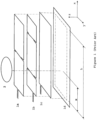
- the antenna 1 and target 2 are arranged as annular discs facing each other with the shaft or other elements such as electrical cables or hydraulic pipes etc., passing through their central apertures for embodiments where such an aperture is envisaged.
- the separation distance z1 between target 2 and antenna 1 is smaller than the distance z2 between antenna 1 and its housing 3 and smaller than the distance z3 between target 2 and its housing 4.
- the gap between housings 3 and 4 and the corresponding antenna 1 and target 2 is filled with epoxy encapsulant 6 and 5.
- epoxy encapsulants may also be loaded with magnetically permeable material such as ferrite particles in order to provide a material which absorbs or screens electromagnetic energy.
- Figure 2 shows an arrangement in which the receive windings of the second arrangement share a common centre line. This is advantageous in minimizing measurement errors from offsets, mechanical installation tolerances or relative displacements between the two bodies in axes other than the measurement axis.
- a large number of plated via holes is required as well as a multiplicity of PCB layers.
- Such a construction impacts measurement performance for various reasons including the imperfections due to the via holes and the varying distance between different parts of the target and antenna windings.
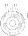
- Figure 4 shows an antenna winding arrangement in which the second arrangement of receive windings laa and 1bb share a common centre line but limits the number of PCB layers and plated via holes. This is achieved by not overlapping the areas which the sine and cosine windings occupy and instead each of the windings occupies preferably three or more segments in which there are one or more loops while preferably maintaining electrical continuity between the segments of the windings.
- first portion being arranged as coarse windings and the second portion arranged as finer pitch, repeating windings.
- the first portion may contain fine and coarse windings with the second portion containing yet finer pitch windings.
- first and second winding arrangements may be arranged as a Vernier pair.
- the first arrangement may have 27 pitches and the other winding 28 so that absolute position measurement may be maintained up to the lowest common multiple.
- the shape of the width variation of the circuits on any of the windings need not be sinusoidal.
- the width variation may be rectangular, triangular, circular or other such shape.
- the antenna's transmit and receive windings may be simplified when an embodiment of the invention is used in a pulse echo mode. In this mode the windings are first of all energised with an AC signal which is then switched off to allow the windings then to receive any signals coming back from a resonating inductive target. Only 2 windings, with known separation, are required and there is no requirement necessarily for electrical balancing. In such instances the windings act as both transmit and receive windings.
- the detector may be constructed with self checking hardware and software. Not only can the electronic circuit's software contain the traditional techniques associated with checking for open circuits, out of bounds measurements etc. but a further inductive target may be used. This may be fixed relative to the antenna or target. Preferably, this second target should have a different resonant frequency than the first target. In this way, a self-diagnostic check may be carried out by measuring the position of the second inductive target. If the second target appears to have moved from its known position past predefined limits then this may be taken as a fault and an alarm or corrective action taken accordingly.
- the electronics circuit should preferably include a frequency tuning circuit so that the exact resonant frequency of the inductive target 2 or devices may be used as the transmit frequency. In this way a maximum amount of transmitted energy goes into producing electrical resonance of the inductive target 2 and, in turn, the inductive target 2 produces maximum electromagnetic signal.
- any material present between the inductive target 2 and antenna 1 is an insulator such as plastic, ceramic or wood.
- a metal barrier may be placed between them so long as the excitation or resonant frequency is sufficiently low to permit the signals to carry through the metal's skin depth. If a metal barrier is essential then preferably the metal has a relatively low magnetic permeability such as non-magnetic stainless steel (e.g. 316 grade stainless). A frequency of 40 kHz is, for example, sufficientto permit the transmission of signals through 1mm thick, non-magnetic 316 grade stainless steel sheet.
- the antenna 1 has been described with co-planar transmit and receive windings. This is preferable but not necessary.
- Temperature can be measured using a thermocouple or resistance device but preferably the resistance of one or more of the antenna windings such as la, 1b, 1c may be used to provide an indication of temperature.
- Measurement of the winding resistance is preferable to measurement by a thermocouple because the windings provide a more representative measurement due to their position along the measurement axis (ratherthan being constrained to a single point as with a thermocouple).
- the amplitude of the signal received from the target 2 or its Q-factor can be taken as generally proportional to its winding resistance and hence indicative of temperature such that the appropriate corrections may be made.
Landscapes
- Physics & Mathematics (AREA)
- General Physics & Mathematics (AREA)
- Engineering & Computer Science (AREA)
- Chemical & Material Sciences (AREA)
- Combustion & Propulsion (AREA)
- Transportation (AREA)
- Mechanical Engineering (AREA)
- Transmission And Conversion Of Sensor Element Output (AREA)
Claims (17)
- Induktiver Positionsdetektor mit einem ersten und einem zweiten Körper (1, 2), die entlang einer Messstrecke relativ zueinander versetzbar sind, wobei der erste Körper (1) Folgendes umfasst:mindestens eine erste (1a, 1b) und eine zweite (1aa, 1bb) Antennenwicklungsanordnung, wobei jede der Antennenwicklungsanordnungen eine Vielzahl benachbarter Empfangswicklungsschleifen, die sich in der Richtung der Messstrecke erstrecken, definiert,und wobei der zweite Körper (2) Folgendes umfasst:einen passiven Schwingkreis, der mindestens eine erste und eine zweite Zielwicklungsanordnung in Reihe mit einem Kondensator (7) einschließt, wobei die zweite Zielwicklungsanordnung eine Vielzahl benachbarter Wicklungsschleifen, die sich in der Richtung der Messstrecke erstrecken, definiert; wobei die erste und die zweite Antennenwicklungsanordnung und die erste und die zweite Zielwicklungsanordnung beide orthogonal von der Messstrecke beabstandet sind, um getrennt zu sein, und der erste und der zweite Körper so positioniert sind, dass die erste und die zweite Zielwicklungsanordnung mindestens einen Teil der ersten (1a, 1b) bzw. der zweiten (1aa, 1bb) Antennenwicklungsanordnung bedecken;dadurch gekennzeichnet, dass- die erste Antennenwicklungsanordnung ferner eine Sendewicklung (1c) aufweist, wobei die Sendewicklung (1c) nur Teil der ersten Antennenwicklungsanordnung ist;- sich die zweite Antennenwicklungsanordnung außerhalb der ersten Antennenwicklungsanordnung befindet und orthogonal von der Sendewicklung (1c) der ersten Antennenwicklungsanordnung beabstandet ist;- die Empfangswicklungsschleifen der ersten Antennenwicklungsanordnung relativ zu denjenigen der zweiten Antennenwicklungsanordnung einen gröberen Abstand aufweisen und- die Polaritäten sowohl benachbarter Empfangswicklungsschleifen der zweiten Antennenwicklungsanordnung (1aa, 1bb) als auch benachbarter Wicklungsschleifen der zweiten Zielwicklungsanordnung magnetisch entgegengesetzt sind.
- Induktiver Positionsdetektor nach Anspruch 1, wobei die zweite Antennenwicklungsanordnung (1aa, 1bb) des ersten Körpers und die zweite Zielwicklungsanordnung des zweiten Körpers bei im Wesentlichen demselben Abstand variieren.
- Induktiver Positionsdetektor nach einem der vorhergehenden Ansprüche, wobei die zweite Antennenwicklungsanordnung (1aa, 1bb) des ersten Körpers mindestens eine erste Reihe benachbarter Empfangswicklungsschleifen und eine zweite Reihe benachbarter Empfangswicklungsschleifen einschließt, die einander überlappen und um einen Abstand von ¼ relativ zueinander entlang der Messstrecke versetzt sind.
- Induktiver Positionsdetektor nach einem der vorhergehenden Ansprüche, wobei die zweite Antennenwicklungsanordnung (1aa, 1bb) des ersten Körpers mindestens eine elektrische Verbindung (10) einschließt; und die zweite Zielwicklungsanordnung des zweiten Körpers mindestens eine elektrische Verbindung zu der ersten Zielwicklungsanordnung einschließt; sich die mindestens eine elektrische Verbindung (10) des ersten Körpers in einem Bereich befindet, der mit dem Bereich, in dem die elektrische Verbindung des zweiten Körpers bereitgestellt ist, nicht überlappt.
- Induktiver Positionsdetektor nach einem der vorhergehenden Ansprüche, wobei die zweite Antennenwicklungsanordnung (1aa, 1bb) des ersten Körpers mindestens eine elektrische Verbindung (10) einschließt; wobei die elektrische Verbindung in einem Bereich ist, der mit dem Bereich der zweiten Zielwicklungsanordnung des zweiten Körpers nicht überlappt.
- Induktiver Positionsdetektor nach einem der vorhergehenden Ansprüche, wobei der erste Körper ferner eine kurzgeschlossene Windung zum Trennen der ersten Antennenwicklungsanordnung des ersten Körpers von der zweiten Antennenwicklungsanordnung davon einschließt.
- Induktiver Positionsdetektor nach einem der vorhergehenden Ansprüche, wobei der erste Körper ferner eine leitfähige Oberfläche zum Trennen der ersten Antennenwicklungsanordnung des ersten Körpers von der zweiten Antennenwicklungsanordnung davon einschließt.
- Induktiver Positionsdetektor nach einem der vorhergehenden Ansprüche, wobei der erste Körper ferner eine magnetisch permeable Oberfläche zum Trennen der ersten Antennenwicklungsanordnung des ersten Körpers von der zweiten Antennenwicklungsanordnung davon einschließt.
- Induktiver Positionsdetektor nach einem der vorhergehenden Ansprüche, wobei die erste Antennenwicklungsanordnung des ersten Körpers von der zweiten Antennenwicklungsanordnung davon um einen zur Messstrecke orthogonalen Abstand getrennt ist, der relativ zu der zur Messstrecke orthogonalen Ausdehnung des Magnetfelds der Sendewicklung groß ist.
- Induktiver Positionsdetektor nach einem der vorhergehenden Ansprüche, wobei der erste und der zweite Körper mindestens eine Leiterplatte umfassen.
- Induktiver Positionsdetektor nach einem der vorhergehenden Ansprüche, wobei die Sendewicklung (1c) und die Empfangswicklungen (1a, 1b) der ersten Antennenwicklungsanordnung elektrisch ausgeglichen sind.
- Induktiver Positionsdetektor nach einem der vorhergehenden Ansprüche, wobei die Wicklungsanordnungen des ersten und des zweiten Körpers im Wesentlichen in einer Ebene angeordnet sind, die parallel zu einer Laminarebene eines Materials ist, das entweder elektrisch leitend oder magnetisch permeabel ist.
- Induktiver Positionsdetektor nach Anspruch 12, wobei die erste (1a, 1b) und die zweite (1aa, 1bb) Antennenwicklungsanordnung des ersten Körpers und die erste und die zweite Zielwicklungsanordnung des zweiten Körpers um einen orthogonalen Zwischenraum, der kleiner als der Abstand zwischen der Ebene der Wicklungen und der Laminarebene des Materials ist, voneinander getrennt sind.
- Induktiver Positionsdetektor nach entweder Anspruch 12 oder Anspruch 13, wobei zwischen der Ebene der Wicklungsanordnungen und der Laminarebene des Materials eine Epoxidvergussmasse bereitgestellt ist.
- Induktiver Positionsdetektor nach Anspruch 14, wobei die Epoxidvergussmasse magnetisch permeable Teilchen enthält.
- Induktiver Positionsdetektor nach einem der vorhergehenden Ansprüche, wobei der erste und der zweite Körper ringförmig sind.
- Induktiver Positionsdetektor nach Anspruch 16, wobei jeder der ringförmigen Körper eine Vielzahl von Segmenten mit verschiedenen Wicklungsanordnungen in einer Vielzahl von Segmenten einschließt.
Applications Claiming Priority (2)
| Application Number | Priority Date | Filing Date | Title |
|---|---|---|---|
| GBGB1420842.5A GB201420842D0 (en) | 2014-11-22 | 2014-11-22 | Detector |
| PCT/GB2015/050216 WO2016079465A1 (en) | 2014-11-22 | 2015-01-29 | Inductive position detector |
Publications (3)
| Publication Number | Publication Date |
|---|---|
| EP3221667A1 EP3221667A1 (de) | 2017-09-27 |
| EP3221667B1 EP3221667B1 (de) | 2018-08-29 |
| EP3221667B3 true EP3221667B3 (de) | 2024-09-11 |
Family
ID=52292429
Family Applications (1)
| Application Number | Title | Priority Date | Filing Date |
|---|---|---|---|
| EP15703624.5A Active EP3221667B3 (de) | 2014-11-22 | 2015-01-29 | Induktiver positionsdetektor |
Country Status (4)
| Country | Link |
|---|---|
| US (1) | US10323959B2 (de) |
| EP (1) | EP3221667B3 (de) |
| GB (1) | GB201420842D0 (de) |
| WO (1) | WO2016079465A1 (de) |
Families Citing this family (16)
| Publication number | Priority date | Publication date | Assignee | Title |
|---|---|---|---|---|
| GB201611173D0 (en) * | 2016-06-28 | 2016-08-10 | Howard Mark A And Kreit Darran | Inductive detector |
| DE102017211190A1 (de) | 2017-06-30 | 2019-01-03 | Robert Bosch Gmbh | Sensorsystem zur Bestimmung mindestens einer Rotationseigenschaft eines rotierenden Elements |
| US11525701B2 (en) * | 2018-01-22 | 2022-12-13 | Melexis Technologies Sa | Inductive position sensor |
| US11692852B2 (en) * | 2020-02-28 | 2023-07-04 | Kyocera Avx Components (Werne) Gmbh | Position sensor having segment sensor element |
| DE102020114014B4 (de) * | 2020-05-26 | 2023-08-24 | Schaeffler Technologies AG & Co. KG | Positionssensor, Zentralausrücker und Kupplungseinrichtung |
| US11248935B2 (en) * | 2020-06-02 | 2022-02-15 | Renesas Electronics America Inc. | Position sensor with varying output slope |
| US11898887B2 (en) | 2021-03-25 | 2024-02-13 | Microchip Technology Incorporated | Sense coil for inductive rotational-position sensing, and related devices, systems, and methods |
| CN117501071A (zh) | 2021-06-11 | 2024-02-02 | 微芯片技术股份有限公司 | 用于感应线性位置感测的感测线圈以及相关设备、系统和方法 |
| WO2023015068A1 (en) | 2021-08-05 | 2023-02-09 | Microchip Technology Incorporated | Inductive angular-position sensors, and related devices, systems, and methods |
| US12339139B2 (en) | 2021-09-28 | 2025-06-24 | Microchip Technology Incorporated | Angular-position sensor |
| EP4184123A1 (de) * | 2021-11-18 | 2023-05-24 | Renesas Electronics America Inc. | Radialer induktiver positionssensor zur erfassung einer drehbewegung, hochauflösendes positionssensorsystem und drehmomentsensorsystem |
| CN118946782A (zh) | 2022-04-01 | 2024-11-12 | 微芯片技术股份有限公司 | 用于感应角位置传感器的目标 |
| US12411001B2 (en) | 2022-04-01 | 2025-09-09 | Microchip Technology Incorporated | Target for inductive angular-position sensing |
| US12163811B2 (en) * | 2022-08-26 | 2024-12-10 | Semiconductor Components Industries, Llc | Inductive angular position sensor |
| US12618692B2 (en) | 2023-02-24 | 2026-05-05 | Microchip Technology Incorporated | Rotary inductive position sensing with 60° phase-shifted sense signals, and related apparatuses and methods |
| FR3151090B1 (fr) | 2023-07-11 | 2025-07-11 | Moving Magnet Tech | Capteur inductif a encombrement optimise |
Family Cites Families (8)
| Publication number | Priority date | Publication date | Assignee | Title |
|---|---|---|---|---|
| DE10320990A1 (de) * | 2003-05-09 | 2004-11-25 | Dr. Johannes Heidenhain Gmbh | Induktiver Drehwinkelsensor und damit ausgestatteter Drehgeber |
| GB0427410D0 (en) | 2004-12-14 | 2005-01-19 | Kreit Darran | Data acquisition system |
| GB0501803D0 (en) * | 2005-01-28 | 2005-03-09 | Howard Mark A | Position encoder |
| US8278945B2 (en) * | 2007-10-24 | 2012-10-02 | Mark Anthony Howard | Inductive position detector |
| GB2488389C (en) * | 2010-12-24 | 2018-08-22 | Cambridge Integrated Circuits Ltd | Position sensing transducer |
| JP5948620B2 (ja) * | 2011-09-16 | 2016-07-06 | 株式会社ミツトヨ | 誘導検出型ロータリエンコーダ |
| US9752899B2 (en) * | 2013-06-13 | 2017-09-05 | Amiteq Co., Ltd. | Inductive position detection device |
| EP3183817B1 (de) * | 2014-08-22 | 2021-05-05 | Balluff GmbH | Induktiver näherungssensor in integrierter bauweise |
-
2014
- 2014-11-22 GB GBGB1420842.5A patent/GB201420842D0/en not_active Ceased
-
2015
- 2015-01-29 EP EP15703624.5A patent/EP3221667B3/de active Active
- 2015-01-29 WO PCT/GB2015/050216 patent/WO2016079465A1/en not_active Ceased
- 2015-01-29 US US15/528,570 patent/US10323959B2/en active Active
Also Published As
| Publication number | Publication date |
|---|---|
| US20170292858A1 (en) | 2017-10-12 |
| US10323959B2 (en) | 2019-06-18 |
| EP3221667A1 (de) | 2017-09-27 |
| EP3221667B1 (de) | 2018-08-29 |
| GB201420842D0 (en) | 2015-01-07 |
| WO2016079465A1 (en) | 2016-05-26 |
Similar Documents
| Publication | Publication Date | Title |
|---|---|---|
| EP3221667B1 (de) | Induktiver positionsdetektor | |
| CN110319860B (zh) | 用于感应位置编码器的发射器和接收器结构 | |
| US10876861B2 (en) | Inductive position detector | |
| US9945653B2 (en) | Inductive position sensor | |
| EP2203719B1 (de) | Detektor | |
| US9410791B2 (en) | Position sensing transducer | |
| US9470505B2 (en) | Position sensing transducer | |
| US6999007B2 (en) | Linear position sensor | |
| EP1828722B1 (de) | Induktiver positionssensor | |
| CN109959398B (zh) | 用于感应式位置编码器的绕组和刻度构造 | |
| EP4148373A2 (de) | Mehrstufige rotierende drehgeber mit induktiven sensoren | |
| WO2020202864A1 (ja) | 磁気式リニアセンサ | |
| CN116576762A (zh) | 线性电感式位置传感器 | |
| GB2500522A (en) | Position Sensing Transducer | |
| US12546628B2 (en) | Inductive encoder with shield structures | |
| WO2005003687A2 (en) | Multiturn absolute rotary position sensor with coarse detector for axial movement and inductive fine detector for rotary movement | |
| HK40008356A (en) | Inductive position detector | |
| Howard | Next-generation inductive transducers for position measurement | |
| HK40008356B (zh) | 感应位置检测器 |
Legal Events
| Date | Code | Title | Description |
|---|---|---|---|
| STAA | Information on the status of an ep patent application or granted ep patent |
Free format text: STATUS: THE INTERNATIONAL PUBLICATION HAS BEEN MADE |
|
| PUAI | Public reference made under article 153(3) epc to a published international application that has entered the european phase |
Free format text: ORIGINAL CODE: 0009012 |
|
| STAA | Information on the status of an ep patent application or granted ep patent |
Free format text: STATUS: REQUEST FOR EXAMINATION WAS MADE |
|
| 17P | Request for examination filed |
Effective date: 20170620 |
|
| AK | Designated contracting states |
Kind code of ref document: A1 Designated state(s): AL AT BE BG CH CY CZ DE DK EE ES FI FR GB GR HR HU IE IS IT LI LT LU LV MC MK MT NL NO PL PT RO RS SE SI SK SM TR |
|
| AX | Request for extension of the european patent |
Extension state: BA ME |
|
| DAX | Request for extension of the european patent (deleted) | ||
| GRAP | Despatch of communication of intention to grant a patent |
Free format text: ORIGINAL CODE: EPIDOSNIGR1 |
|
| STAA | Information on the status of an ep patent application or granted ep patent |
Free format text: STATUS: GRANT OF PATENT IS INTENDED |
|
| RIC1 | Information provided on ipc code assigned before grant |
Ipc: G01D 5/20 20060101AFI20180530BHEP Ipc: B62D 1/185 20060101ALI20180530BHEP |
|
| INTG | Intention to grant announced |
Effective date: 20180614 |
|
| GRAS | Grant fee paid |
Free format text: ORIGINAL CODE: EPIDOSNIGR3 |
|
| GRAA | (expected) grant |
Free format text: ORIGINAL CODE: 0009210 |
|
| STAA | Information on the status of an ep patent application or granted ep patent |
Free format text: STATUS: THE PATENT HAS BEEN GRANTED |
|
| RAP1 | Party data changed (applicant data changed or rights of an application transferred) |
Owner name: ZETTLEX (UK) LIMITED |
|
| RIN1 | Information on inventor provided before grant (corrected) |
Inventor name: KREIT, DARRAN Inventor name: HOWARD, MARK ANTHONY |
|
| AK | Designated contracting states |
Kind code of ref document: B1 Designated state(s): AL AT BE BG CH CY CZ DE DK EE ES FI FR GB GR HR HU IE IS IT LI LT LU LV MC MK MT NL NO PL PT RO RS SE SI SK SM TR |
|
| REG | Reference to a national code |
Ref country code: GB Ref legal event code: FG4D |
|
| REG | Reference to a national code |
Ref country code: CH Ref legal event code: EP |
|
| REG | Reference to a national code |
Ref country code: AT Ref legal event code: REF Ref document number: 1035656 Country of ref document: AT Kind code of ref document: T Effective date: 20180915 |
|
| REG | Reference to a national code |
Ref country code: IE Ref legal event code: FG4D |
|
| REG | Reference to a national code |
Ref country code: DE Ref legal event code: R096 Ref document number: 602015015482 Country of ref document: DE |
|
| REG | Reference to a national code |
Ref country code: NL Ref legal event code: MP Effective date: 20180829 |
|
| REG | Reference to a national code |
Ref country code: LT Ref legal event code: MG4D |
|
| PG25 | Lapsed in a contracting state [announced via postgrant information from national office to epo] |
Ref country code: LT Free format text: LAPSE BECAUSE OF FAILURE TO SUBMIT A TRANSLATION OF THE DESCRIPTION OR TO PAY THE FEE WITHIN THE PRESCRIBED TIME-LIMIT Effective date: 20180829 Ref country code: GR Free format text: LAPSE BECAUSE OF FAILURE TO SUBMIT A TRANSLATION OF THE DESCRIPTION OR TO PAY THE FEE WITHIN THE PRESCRIBED TIME-LIMIT Effective date: 20181130 Ref country code: FI Free format text: LAPSE BECAUSE OF FAILURE TO SUBMIT A TRANSLATION OF THE DESCRIPTION OR TO PAY THE FEE WITHIN THE PRESCRIBED TIME-LIMIT Effective date: 20180829 Ref country code: NL Free format text: LAPSE BECAUSE OF FAILURE TO SUBMIT A TRANSLATION OF THE DESCRIPTION OR TO PAY THE FEE WITHIN THE PRESCRIBED TIME-LIMIT Effective date: 20180829 Ref country code: SE Free format text: LAPSE BECAUSE OF FAILURE TO SUBMIT A TRANSLATION OF THE DESCRIPTION OR TO PAY THE FEE WITHIN THE PRESCRIBED TIME-LIMIT Effective date: 20180829 Ref country code: BG Free format text: LAPSE BECAUSE OF FAILURE TO SUBMIT A TRANSLATION OF THE DESCRIPTION OR TO PAY THE FEE WITHIN THE PRESCRIBED TIME-LIMIT Effective date: 20181129 Ref country code: IS Free format text: LAPSE BECAUSE OF FAILURE TO SUBMIT A TRANSLATION OF THE DESCRIPTION OR TO PAY THE FEE WITHIN THE PRESCRIBED TIME-LIMIT Effective date: 20181229 Ref country code: RS Free format text: LAPSE BECAUSE OF FAILURE TO SUBMIT A TRANSLATION OF THE DESCRIPTION OR TO PAY THE FEE WITHIN THE PRESCRIBED TIME-LIMIT Effective date: 20180829 Ref country code: NO Free format text: LAPSE BECAUSE OF FAILURE TO SUBMIT A TRANSLATION OF THE DESCRIPTION OR TO PAY THE FEE WITHIN THE PRESCRIBED TIME-LIMIT Effective date: 20181129 |
|
| REG | Reference to a national code |
Ref country code: AT Ref legal event code: MK05 Ref document number: 1035656 Country of ref document: AT Kind code of ref document: T Effective date: 20180829 |
|
| PG25 | Lapsed in a contracting state [announced via postgrant information from national office to epo] |
Ref country code: HR Free format text: LAPSE BECAUSE OF FAILURE TO SUBMIT A TRANSLATION OF THE DESCRIPTION OR TO PAY THE FEE WITHIN THE PRESCRIBED TIME-LIMIT Effective date: 20180829 Ref country code: LV Free format text: LAPSE BECAUSE OF FAILURE TO SUBMIT A TRANSLATION OF THE DESCRIPTION OR TO PAY THE FEE WITHIN THE PRESCRIBED TIME-LIMIT Effective date: 20180829 Ref country code: AL Free format text: LAPSE BECAUSE OF FAILURE TO SUBMIT A TRANSLATION OF THE DESCRIPTION OR TO PAY THE FEE WITHIN THE PRESCRIBED TIME-LIMIT Effective date: 20180829 |
|
| PG25 | Lapsed in a contracting state [announced via postgrant information from national office to epo] |
Ref country code: RO Free format text: LAPSE BECAUSE OF FAILURE TO SUBMIT A TRANSLATION OF THE DESCRIPTION OR TO PAY THE FEE WITHIN THE PRESCRIBED TIME-LIMIT Effective date: 20180829 Ref country code: CZ Free format text: LAPSE BECAUSE OF FAILURE TO SUBMIT A TRANSLATION OF THE DESCRIPTION OR TO PAY THE FEE WITHIN THE PRESCRIBED TIME-LIMIT Effective date: 20180829 Ref country code: IT Free format text: LAPSE BECAUSE OF FAILURE TO SUBMIT A TRANSLATION OF THE DESCRIPTION OR TO PAY THE FEE WITHIN THE PRESCRIBED TIME-LIMIT Effective date: 20180829 Ref country code: EE Free format text: LAPSE BECAUSE OF FAILURE TO SUBMIT A TRANSLATION OF THE DESCRIPTION OR TO PAY THE FEE WITHIN THE PRESCRIBED TIME-LIMIT Effective date: 20180829 Ref country code: AT Free format text: LAPSE BECAUSE OF FAILURE TO SUBMIT A TRANSLATION OF THE DESCRIPTION OR TO PAY THE FEE WITHIN THE PRESCRIBED TIME-LIMIT Effective date: 20180829 Ref country code: PL Free format text: LAPSE BECAUSE OF FAILURE TO SUBMIT A TRANSLATION OF THE DESCRIPTION OR TO PAY THE FEE WITHIN THE PRESCRIBED TIME-LIMIT Effective date: 20180829 Ref country code: ES Free format text: LAPSE BECAUSE OF FAILURE TO SUBMIT A TRANSLATION OF THE DESCRIPTION OR TO PAY THE FEE WITHIN THE PRESCRIBED TIME-LIMIT Effective date: 20180829 |
|
| PG25 | Lapsed in a contracting state [announced via postgrant information from national office to epo] |
Ref country code: SK Free format text: LAPSE BECAUSE OF FAILURE TO SUBMIT A TRANSLATION OF THE DESCRIPTION OR TO PAY THE FEE WITHIN THE PRESCRIBED TIME-LIMIT Effective date: 20180829 Ref country code: DK Free format text: LAPSE BECAUSE OF FAILURE TO SUBMIT A TRANSLATION OF THE DESCRIPTION OR TO PAY THE FEE WITHIN THE PRESCRIBED TIME-LIMIT Effective date: 20180829 Ref country code: SM Free format text: LAPSE BECAUSE OF FAILURE TO SUBMIT A TRANSLATION OF THE DESCRIPTION OR TO PAY THE FEE WITHIN THE PRESCRIBED TIME-LIMIT Effective date: 20180829 |
|
| REG | Reference to a national code |
Ref country code: DE Ref legal event code: R097 Ref document number: 602015015482 Country of ref document: DE |
|
| PLBE | No opposition filed within time limit |
Free format text: ORIGINAL CODE: 0009261 |
|
| STAA | Information on the status of an ep patent application or granted ep patent |
Free format text: STATUS: NO OPPOSITION FILED WITHIN TIME LIMIT |
|
| 26N | No opposition filed |
Effective date: 20190531 |
|
| PG25 | Lapsed in a contracting state [announced via postgrant information from national office to epo] |
Ref country code: SI Free format text: LAPSE BECAUSE OF FAILURE TO SUBMIT A TRANSLATION OF THE DESCRIPTION OR TO PAY THE FEE WITHIN THE PRESCRIBED TIME-LIMIT Effective date: 20180829 Ref country code: MC Free format text: LAPSE BECAUSE OF FAILURE TO SUBMIT A TRANSLATION OF THE DESCRIPTION OR TO PAY THE FEE WITHIN THE PRESCRIBED TIME-LIMIT Effective date: 20180829 |
|
| REG | Reference to a national code |
Ref country code: CH Ref legal event code: PL |
|
| PG25 | Lapsed in a contracting state [announced via postgrant information from national office to epo] |
Ref country code: LU Free format text: LAPSE BECAUSE OF NON-PAYMENT OF DUE FEES Effective date: 20190129 |
|
| REG | Reference to a national code |
Ref country code: BE Ref legal event code: MM Effective date: 20190131 |
|
| REG | Reference to a national code |
Ref country code: IE Ref legal event code: MM4A |
|
| PG25 | Lapsed in a contracting state [announced via postgrant information from national office to epo] |
Ref country code: BE Free format text: LAPSE BECAUSE OF NON-PAYMENT OF DUE FEES Effective date: 20190131 |
|
| PG25 | Lapsed in a contracting state [announced via postgrant information from national office to epo] |
Ref country code: CH Free format text: LAPSE BECAUSE OF NON-PAYMENT OF DUE FEES Effective date: 20190131 Ref country code: LI Free format text: LAPSE BECAUSE OF NON-PAYMENT OF DUE FEES Effective date: 20190131 |
|
| PG25 | Lapsed in a contracting state [announced via postgrant information from national office to epo] |
Ref country code: IE Free format text: LAPSE BECAUSE OF NON-PAYMENT OF DUE FEES Effective date: 20190129 |
|
| PG25 | Lapsed in a contracting state [announced via postgrant information from national office to epo] |
Ref country code: TR Free format text: LAPSE BECAUSE OF FAILURE TO SUBMIT A TRANSLATION OF THE DESCRIPTION OR TO PAY THE FEE WITHIN THE PRESCRIBED TIME-LIMIT Effective date: 20180829 |
|
| REG | Reference to a national code |
Ref country code: DE Ref legal event code: R055 Ref document number: 602015015482 Country of ref document: DE |
|
| PLCP | Request for limitation filed |
Free format text: ORIGINAL CODE: EPIDOSNLIM1 |
|
| PLCQ | Request for limitation of patent found admissible |
Free format text: ORIGINAL CODE: 0009231 |
|
| PG25 | Lapsed in a contracting state [announced via postgrant information from national office to epo] |
Ref country code: MT Free format text: LAPSE BECAUSE OF NON-PAYMENT OF DUE FEES Effective date: 20190129 Ref country code: PT Free format text: LAPSE BECAUSE OF FAILURE TO SUBMIT A TRANSLATION OF THE DESCRIPTION OR TO PAY THE FEE WITHIN THE PRESCRIBED TIME-LIMIT Effective date: 20181229 |
|
| LIM1 | Request for limitation found admissible |
Free format text: SEQUENCE NO: 1; FILED AFTER OPPOSITION PERIOD Filing date: 20200529 Effective date: 20200529 |
|
| PG25 | Lapsed in a contracting state [announced via postgrant information from national office to epo] |
Ref country code: CY Free format text: LAPSE BECAUSE OF FAILURE TO SUBMIT A TRANSLATION OF THE DESCRIPTION OR TO PAY THE FEE WITHIN THE PRESCRIBED TIME-LIMIT Effective date: 20180829 |
|
| PG25 | Lapsed in a contracting state [announced via postgrant information from national office to epo] |
Ref country code: HU Free format text: LAPSE BECAUSE OF FAILURE TO SUBMIT A TRANSLATION OF THE DESCRIPTION OR TO PAY THE FEE WITHIN THE PRESCRIBED TIME-LIMIT; INVALID AB INITIO Effective date: 20150129 |
|
| PG25 | Lapsed in a contracting state [announced via postgrant information from national office to epo] |
Ref country code: MK Free format text: LAPSE BECAUSE OF FAILURE TO SUBMIT A TRANSLATION OF THE DESCRIPTION OR TO PAY THE FEE WITHIN THE PRESCRIBED TIME-LIMIT Effective date: 20180829 |
|
| REG | Reference to a national code |
Ref country code: DE Ref legal event code: R082 Ref document number: 602015015482 Country of ref document: DE Representative=s name: KEENWAY PATENTANWAELTE NEUMANN HEINE TARUTTIS , DE |
|
| PLCR | Communication despatched that request for limitation of patent was allowed |
Free format text: ORIGINAL CODE: 0009245 |
|
| REG | Reference to a national code |
Ref country code: DE Ref legal event code: R056 Ref document number: 602015015482 Country of ref document: DE |
|
| PUAM | (expected) publication of b3 document |
Free format text: ORIGINAL CODE: 0009410 |
|
| STAA | Information on the status of an ep patent application or granted ep patent |
Free format text: STATUS: THE PATENT HAS BEEN LIMITED |
|
| PGFP | Annual fee paid to national office [announced via postgrant information from national office to epo] |
Ref country code: GB Payment date: 20260130 Year of fee payment: 12 |
|
| PGFP | Annual fee paid to national office [announced via postgrant information from national office to epo] |
Ref country code: DE Payment date: 20260121 Year of fee payment: 12 |
|
| PGFP | Annual fee paid to national office [announced via postgrant information from national office to epo] |
Ref country code: FR Payment date: 20260107 Year of fee payment: 12 |