EP3221625B1 - Verfahren zum installieren einer flexiblen leitung mit einer aussenhülle zur abgrenzung eines innenraums - Google Patents
Verfahren zum installieren einer flexiblen leitung mit einer aussenhülle zur abgrenzung eines innenraums Download PDFInfo
- Publication number
- EP3221625B1 EP3221625B1 EP15801718.6A EP15801718A EP3221625B1 EP 3221625 B1 EP3221625 B1 EP 3221625B1 EP 15801718 A EP15801718 A EP 15801718A EP 3221625 B1 EP3221625 B1 EP 3221625B1
- Authority
- EP
- European Patent Office
- Prior art keywords
- orifice
- pipe
- sheath
- fluid
- interior volume
- Prior art date
- Legal status (The legal status is an assumption and is not a legal conclusion. Google has not performed a legal analysis and makes no representation as to the accuracy of the status listed.)
- Active
Links
- 238000000034 method Methods 0.000 title claims description 18
- 239000012530 fluid Substances 0.000 claims description 41
- 239000007788 liquid Substances 0.000 claims description 37
- XLYOFNOQVPJJNP-UHFFFAOYSA-N water Substances O XLYOFNOQVPJJNP-UHFFFAOYSA-N 0.000 claims description 24
- 239000002033 PVDF binder Substances 0.000 description 10
- 229920002981 polyvinylidene fluoride Polymers 0.000 description 10
- LYCAIKOWRPUZTN-UHFFFAOYSA-N Ethylene glycol Chemical compound OCCO LYCAIKOWRPUZTN-UHFFFAOYSA-N 0.000 description 9
- 239000002184 metal Substances 0.000 description 9
- 229910052751 metal Inorganic materials 0.000 description 9
- 239000003795 chemical substances by application Substances 0.000 description 7
- 239000007789 gas Substances 0.000 description 7
- 238000007654 immersion Methods 0.000 description 6
- 238000009434 installation Methods 0.000 description 6
- 238000004519 manufacturing process Methods 0.000 description 6
- 230000036961 partial effect Effects 0.000 description 6
- 230000011664 signaling Effects 0.000 description 6
- 238000004804 winding Methods 0.000 description 6
- 239000004952 Polyamide Substances 0.000 description 5
- 238000005260 corrosion Methods 0.000 description 5
- 230000007797 corrosion Effects 0.000 description 5
- 239000003208 petroleum Substances 0.000 description 5
- 229920002647 polyamide Polymers 0.000 description 5
- -1 polyethylene Polymers 0.000 description 5
- 239000002131 composite material Substances 0.000 description 4
- 239000002861 polymer material Substances 0.000 description 4
- 230000001681 protective effect Effects 0.000 description 4
- 238000011144 upstream manufacturing Methods 0.000 description 4
- 229920000271 Kevlar® Polymers 0.000 description 3
- OKKJLVBELUTLKV-UHFFFAOYSA-N Methanol Chemical compound OC OKKJLVBELUTLKV-UHFFFAOYSA-N 0.000 description 3
- 239000004698 Polyethylene Substances 0.000 description 3
- 229920001494 Technora Polymers 0.000 description 3
- 239000004760 aramid Substances 0.000 description 3
- 229920003235 aromatic polyamide Polymers 0.000 description 3
- QVGXLLKOCUKJST-UHFFFAOYSA-N atomic oxygen Chemical compound [O] QVGXLLKOCUKJST-UHFFFAOYSA-N 0.000 description 3
- 206010016256 fatigue Diseases 0.000 description 3
- 229920002313 fluoropolymer Polymers 0.000 description 3
- WGCNASOHLSPBMP-UHFFFAOYSA-N hydroxyacetaldehyde Natural products OCC=O WGCNASOHLSPBMP-UHFFFAOYSA-N 0.000 description 3
- 239000004761 kevlar Substances 0.000 description 3
- 239000001301 oxygen Substances 0.000 description 3
- 229910052760 oxygen Inorganic materials 0.000 description 3
- 230000035515 penetration Effects 0.000 description 3
- 229920000573 polyethylene Polymers 0.000 description 3
- 229920000098 polyolefin Polymers 0.000 description 3
- 239000013535 sea water Substances 0.000 description 3
- 239000004950 technora Substances 0.000 description 3
- RWSOTUBLDIXVET-UHFFFAOYSA-N Dihydrogen sulfide Chemical compound S RWSOTUBLDIXVET-UHFFFAOYSA-N 0.000 description 2
- LFQSCWFLJHTTHZ-UHFFFAOYSA-N Ethanol Chemical compound CCO LFQSCWFLJHTTHZ-UHFFFAOYSA-N 0.000 description 2
- 239000000654 additive Substances 0.000 description 2
- 238000005452 bending Methods 0.000 description 2
- 238000002788 crimping Methods 0.000 description 2
- 239000003112 inhibitor Substances 0.000 description 2
- 239000004033 plastic Substances 0.000 description 2
- 229920003023 plastic Polymers 0.000 description 2
- 230000002829 reductive effect Effects 0.000 description 2
- 229920000049 Carbon (fiber) Polymers 0.000 description 1
- 239000004743 Polypropylene Substances 0.000 description 1
- 230000009172 bursting Effects 0.000 description 1
- 239000004917 carbon fiber Substances 0.000 description 1
- 230000007423 decrease Effects 0.000 description 1
- 230000000694 effects Effects 0.000 description 1
- 239000003365 glass fiber Substances 0.000 description 1
- 229930195733 hydrocarbon Natural products 0.000 description 1
- 150000002430 hydrocarbons Chemical class 0.000 description 1
- 230000002706 hydrostatic effect Effects 0.000 description 1
- 238000002347 injection Methods 0.000 description 1
- 239000007924 injection Substances 0.000 description 1
- 239000000314 lubricant Substances 0.000 description 1
- 239000011159 matrix material Substances 0.000 description 1
- 239000000203 mixture Substances 0.000 description 1
- 230000003287 optical effect Effects 0.000 description 1
- 210000000056 organ Anatomy 0.000 description 1
- 230000000149 penetrating effect Effects 0.000 description 1
- 229920001155 polypropylene Polymers 0.000 description 1
- 239000000843 powder Substances 0.000 description 1
- 230000002265 prevention Effects 0.000 description 1
- 239000011814 protection agent Substances 0.000 description 1
- 230000003014 reinforcing effect Effects 0.000 description 1
- 230000000284 resting effect Effects 0.000 description 1
- 230000002441 reversible effect Effects 0.000 description 1
- 239000000243 solution Substances 0.000 description 1
- 229920001169 thermoplastic Polymers 0.000 description 1
- 239000004416 thermosoftening plastic Substances 0.000 description 1
Images


Classifications
-
- F—MECHANICAL ENGINEERING; LIGHTING; HEATING; WEAPONS; BLASTING
- F16—ENGINEERING ELEMENTS AND UNITS; GENERAL MEASURES FOR PRODUCING AND MAINTAINING EFFECTIVE FUNCTIONING OF MACHINES OR INSTALLATIONS; THERMAL INSULATION IN GENERAL
- F16L—PIPES; JOINTS OR FITTINGS FOR PIPES; SUPPORTS FOR PIPES, CABLES OR PROTECTIVE TUBING; MEANS FOR THERMAL INSULATION IN GENERAL
- F16L11/00—Hoses, i.e. flexible pipes
- F16L11/20—Double-walled hoses, i.e. two concentric hoses
-
- F—MECHANICAL ENGINEERING; LIGHTING; HEATING; WEAPONS; BLASTING
- F16—ENGINEERING ELEMENTS AND UNITS; GENERAL MEASURES FOR PRODUCING AND MAINTAINING EFFECTIVE FUNCTIONING OF MACHINES OR INSTALLATIONS; THERMAL INSULATION IN GENERAL
- F16L—PIPES; JOINTS OR FITTINGS FOR PIPES; SUPPORTS FOR PIPES, CABLES OR PROTECTIVE TUBING; MEANS FOR THERMAL INSULATION IN GENERAL
- F16L11/00—Hoses, i.e. flexible pipes
- F16L11/04—Hoses, i.e. flexible pipes made of rubber or flexible plastics
- F16L11/08—Hoses, i.e. flexible pipes made of rubber or flexible plastics with reinforcements embedded in the wall
- F16L11/081—Hoses, i.e. flexible pipes made of rubber or flexible plastics with reinforcements embedded in the wall comprising one or more layers of a helically wound cord or wire
- F16L11/083—Hoses, i.e. flexible pipes made of rubber or flexible plastics with reinforcements embedded in the wall comprising one or more layers of a helically wound cord or wire three or more layers
-
- F—MECHANICAL ENGINEERING; LIGHTING; HEATING; WEAPONS; BLASTING
- F16—ENGINEERING ELEMENTS AND UNITS; GENERAL MEASURES FOR PRODUCING AND MAINTAINING EFFECTIVE FUNCTIONING OF MACHINES OR INSTALLATIONS; THERMAL INSULATION IN GENERAL
- F16L—PIPES; JOINTS OR FITTINGS FOR PIPES; SUPPORTS FOR PIPES, CABLES OR PROTECTIVE TUBING; MEANS FOR THERMAL INSULATION IN GENERAL
- F16L33/00—Arrangements for connecting hoses to rigid members; Rigid hose connectors, i.e. single members engaging both hoses
- F16L33/01—Arrangements for connecting hoses to rigid members; Rigid hose connectors, i.e. single members engaging both hoses adapted for hoses having a multi-layer wall
Definitions
- the present invention relates to a method for installing a flexible line comprising an outer sheath delimiting an interior volume according to the preamble of claim 1.
- the flexible line is in particular a flexible pipe as described in the normative documents published by American Petroleum Institute (API), API 17J “Specification for Unbonded Flexible Pipe” , and API RP17B “Recommended Practice for Flexible Pipes” .
- the flexible pipe is advantageously of the unbonded type.
- the flexible pipe is a composite bundle of the “integrated production bundle” type, comprising at least one fluid transport tube and a set of electric or optical cables suitable for transporting electric or hydraulic power or information between the bottom and the surface of the body of water.
- the flexible line is an umbilical, as described in the normative documents published by American Petroleum Institute (API), API17E “Specification for Subsea Umbilicals” .
- Flexible pipes generally comprise an outer protective sheath defining an interior volume and at least one impermeable sheath placed inside the interior volume.
- This impermeable sheath is for example a pressure sheath delimiting a fluid circulation passage or an intermediate sheath arranged between the pressure sheath and the outer sheath.
- Tensile armor layers formed by layers of generally metallic wires are arranged in the annular space between the impermeable sheath and the outer sheath, to ensure good tensile strength.
- the length of the pipe increases significantly, especially for pipes suitable for great depths.
- This length is for example of the order of 2000 m, or even more.
- the great length of suspended pipe generates a great tension on the tensile armours. Since the armours are axially tensioned, they produce a high radial contact pressure on the impermeable sheath as well as the underlying layers that they surround. Furthermore, since the hydrostatic pressure external to the pipe is high at great depths, for example of the order of 250 barg, the radial contact pressure generated by the tensile armor on the impermeable sheath increases further.
- this radial contact pressure is likely to cause creep of the impermeable sheath at the interface with the tensile armor layers which can lead to an increase in the bending stiffness of the pipe, but also to reduce the fatigue resistance of the armours, which can, in certain critical cases, significantly reduce the service life of the pipe.
- WO2013005000 describes a flexible pipe in which gases from the ring finger are evacuated to the outside through a non-return valve.
- WO0017479 also describes a flexible pipe in which the gases from the ring finger are evacuated towards a central conduit of the flexible line through a non-return valve combined in a particular embodiment with a pump.
- An object of the invention is to provide a method of laying a flexible line which ensures adequate service life for the flexible line, even at great depths.
- the invention relates to a method according to claim 1.
- outside or outside and “inside” or “inside” are generally understood to be radial with respect to an axis A-A' of the pipe, the term “outside” being understood as relatively further radially from the axis A-A' and the term “inner” being understood as relatively closer radially to the axis A-A' of the pipe.
- upstream and downstream are generally understood with respect to the normal direction of circulation of a petroleum fluid within the pipe.
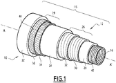
- a first flexible line according to the invention formed by a flexible pipe 10, is partially illustrated by the figure 1 , 2 , and 4 .
- the flexible pipe 10 comprises a central section 12 illustrated in part on the figure 1 . It comprises, at each of the axial ends of the central section 12, an end fitting 14, partially visible on the figure 2 and 4 .
- the pipe 10 delimits, in its interior volume 15, a central passage 16 for the circulation of a fluid, advantageously a petroleum fluid.
- the central passage 16 extends along an axis A-A', which it contains, between the upstream end and the downstream end of the pipe 10. It opens through the end pieces 14.
- the diameter of the central passage 16 is advantageously between 50 mm (2") and 500 mm (20").
- the fluid conveyed by the pipe is for example a gas or a liquid extracted from the seabed.
- the flexible pipe 10 is intended to be placed across a body of water (not shown) in a fluid exploitation installation, in particular hydrocarbons.
- the body of water is, for example, a sea, a lake or an ocean.
- the depth of the stretch of water in line with the fluid exploitation installation is for example between 50 m and 4000 m.
- the fluid exploitation installation comprises a surface assembly, generally floating, and a bottom assembly (not shown) which are generally connected to each other by the flexible pipe 10.
- the flexible pipe 10 is in this example an “unbonded” pipe (designated by the English term “unbonded”).
- At least two adjacent layers of flexible pipe 10 are free to move longitudinally relative to each other when the pipe flexes.
- all of the adjacent layers of the flexible pipe are free to move relative to each other.
- Such conduct is for example described in the normative documents published by the American Petroleum Institute (API), API 17J, and API RP17B.
- the pipe 10 delimits a plurality of concentric layers around the axis A-A′, which extend continuously along the central section 12 as far as the end pieces 14 located at the ends of the pipe.
- the pipe 10 here comprises at least a first sheath 20 based on polymer material constituting a pressure sheath.
- the pipe 10 comprises a second outer sheath 22, intended to protect the pipe 10 and, in the particular example shown in the figure 1 , an intermediate sealed sheath 24 interposed between the inner sheath 20 and the outer sheath 22.
- the intermediate sheath 24 defines with the internal sheath 20, an internal annular space 26. It defines with the external sheath 22 an external annular space 28 reinforcing the intermediate sheath 24.
- the pipe 10 defines at least one orifice 29 for introducing liquid into the outer annular space 28 and a non-return member 31, capable of allowing the introduction of liquid to at least partially flood the outer annular space 28 in a zone upstream of the pipe 10 during the installation of the pipe 10, then to close once the outer annular space 28 has been flooded.
- the pipe 10 in the internal annular space 26, the pipe 10 comprises a pressure vault 30, and optionally, an internal hoop 32 wound around the pressure vault 30.
- the pipe 10 comprises a plurality of internal tensile armor layers 34, 36 arranged externally around the intermediate sheath 24.
- the pipe 10 comprises, in the internal annular space 26, a plurality of internal tensile armor layers 34, 36 disposed externally with respect to the pressure vault 30 and with respect to the hoop 32 and in the annular space external, a plurality of external tensile armor layers 38, 40 externally arranged around the intermediate sheath 24.
- the tensile armor layers 38, 40 are replaced by a pressure vault formed from a profiled metal wire having a geometry in the form of T, U, K , X or I.
- the pipe 10 further comprises an internal carcass 42 disposed inside the internal sheath 20.
- the carcass 42 when present, is formed for example of a profiled metal strip, wound in a spiral.
- the coils of the strip are advantageously stapled to each other, which makes it possible to take up the radial crushing forces.
- the helical winding of the profiled metal strip forming the carcass 42 has a short pitch, that is to say it has a helix angle of absolute value close to 90°, typically between 75° and 90°.
- the carcass 42 is arranged inside the internal sheath 20.
- the pipe is then designated by the English term "rough bore" because of the geometry of the carcass 42.
- the flexible pipe 10 has no internal carcass 42, it is then designated by the English term “smooth bore”.
- the inner sheath 20 is intended to seal the fluid transported in the passage 16 in a sealed manner. It is formed from a polymer material, for example based on a polyolefin such as polyethylene, based on a polyamide such as as PA11 or PA12, or based on a fluorinated polymer such as polyvinylidene fluoride (PVDF).
- a polymer material for example based on a polyolefin such as polyethylene, based on a polyamide such as as PA11 or PA12, or based on a fluorinated polymer such as polyvinylidene fluoride (PVDF).
- PVDF polyvinylidene fluoride
- the thickness of the internal sheath 20 is for example between 5 mm and 20 mm.
- the pressure vault 30 is intended to take up the forces linked to the pressure prevailing inside the internal sheath 20. It is for example formed of a metal profiled wire wrapped in a helix around the sheath 20.
- the profiled wire preferably has a geometry, in particular Z-shaped. The Z-shaped geometry makes it possible to improve the general mechanical strength of the pipe 10 and also makes it possible to reduce its mass.
- the profiled wire has a T-, U-, K-, X- or I-shaped geometry.
- the pressure vault 30 is wound in a short-pitch helix around the internal sheath 20, that is to say with a helix angle of absolute value close to 90°, typically between 75° and 90°.
- the hoop 32 when present, is constituted by a spiral winding of at least one wire, advantageously of rectangular cross-section around the pressure vault 30.
- the superposition of several wires wound around the pressure vault 30 can advantageously replace a total thickness of hoop 32 given. This makes it possible to increase the resistance to bursting of the pipe 10, but also to reduce the risk of fatigue by friction.
- the winding of at least one wire is short-pitch, that is to say with a helix angle of absolute value close to 90°, typically between 75° and 90°.
- the pressure vault 30 and the hoop 32 are replaced by a pressure vault of greater thickness formed from a profiled metal wire having a T-shaped geometry, U, K, X or I, and/or from at least one aramid strip with high mechanical strength (Technora ® or Kevlar ® ), and/or from at least one composite strip comprising a thermoplastic matrix in which carbon fibers or glass fibers are embedded.
- a pressure vault of greater thickness formed from a profiled metal wire having a T-shaped geometry, U, K, X or I, and/or from at least one aramid strip with high mechanical strength (Technora ® or Kevlar ® ), and/or from at least one composite strip comprising a thermoplastic matrix in which carbon fibers or glass fibers are embedded.
- the flexible pipe does not include a pressure vault.
- Such a flexible pipe structure is called "balanced" (not shown).
- the conduit includes at least one pair of tensile strength cross-weave layers disposed above the inner sheath.
- the armours each comprise metal wires wound at a long pitch, in opposite directions, around the internal sheath according to a helix angle of absolute value comprised between 50° and 60°, preferably 55° with respect to the longitudinal axis of the conduct. This means that the wires of the first armor layer are wound with a long pitch, according to a helix angle between +50° and +60° and the wires of the second armor layer are wound with a long pitch, according to a winding angle between -50° and -60°.
- the flexible pipe 10 comprises at least one pair of internal armor layers 34, 36.
- the flexible pipe 10 comprises several pairs of internal armor layers 34, 36 superimposed on each other, for example two pairs of internal armor layers 34, 36.
- Each pair comprises a first layer of internal armor 34 applied to the intermediate sheath 24 or to another pair of layers of internal armor, and a second layer of internal armor 36, arranged around the first layer of internal armor 34 .
- Each layer of internal armor 34, 36 comprises at least one longitudinal armor element 44 wound at a long pitch around the axis A-A' of the pipe 10.
- long-pitch wound it is meant that the absolute value of the helix angle is less than 60°, and is typically between 20° and 60°.
- the absolute value of the helix angle of each layer of internal armor 34, 36 is less than 45°, and is in particular between 20° and 30°, and is approximately equal to 25°.
- the armor elements 44 of a first layer 34 are wrapped generally at an opposite angle to the armor elements 44 of a second layer 36.
- the angle of wrap of the armor elements 44 of the first layer 34 is equal to + ⁇ , ⁇ being between 20° and 60°
- the winding angle of the armor elements 44 of the second layer 36 placed in contact with the first layer 34 is for example - a, with ⁇ between 20° and 60°.
- the armor elements 44 are for example formed by metal wires or composite material, or by tapes with high mechanical resistance.
- each layer of armor 34, 36 rests on at least one anti-wear strip.
- the anti-wear strip is for example made of plastic, in particular based on a polyamide or a polyvinylidene fluoride (PVDF). It has a thickness less than the thickness of each sheath 20, 22, 24.
- a retaining tape such as an aramid tape with high mechanical resistance (Technora ® or Kevlar ® ) is wound around the second layer of external armor 36 furthest outside with respect to the axis A- A', to provide mechanical support for the outer armor layers 34, 36.
- the intermediate sheath 24 is intended to confine the internal annular space 26.
- the external annular space 28 intended to be flooded is separated in a sealed manner from the internal annular space 26 intended to remain dry.
- the intermediate sheath 24 is advantageously made of a polymer material, in particular based on a polyolefin, such as polyethylene, based on a polyamide, such as as PA11 or PA12, or based on a fluorinated polymer such as polyvinylidene fluoride (PVDF).
- a polyolefin such as polyethylene
- a polyamide such as as PA11 or PA12
- PVDF polyvinylidene fluoride
- the thickness of the intermediate sheath 24 is for example between 5 mm and 15 mm.
- the flexible pipe 10 comprises at least one pair of outer armor layers 38, 40.
- the flexible pipe 10 comprises several pairs of outer armor layers 38, 40 superimposed on each other, for example two pairs of outer armor layers 38, 40.
- Each pair comprises a first outer armor layer 38, applied to the intermediate sheath 24 or to another pair of outer armor layers, and a second outer armor layer 40, disposed around the first outer armor layer 38.
- Each outer armor layer 38, 40 comprises at least one longitudinal armor element 44 wound at a long pitch around the axis A-A' of the pipe 10.
- long-pitch wound it is meant that the absolute value of the helix angle is less than 60°, and is typically between 20° and 60°.
- the absolute value of the helix angle of each outer armor layer 38, 40 is greater than 45°, and is in particular between 50° and 60°, and is approximately equal to 55°.
- the weave elements 44 of a first layer 38 are wrapped generally at an opposite angle to the weave elements 44 of a second layer 40.
- the angle of wrap of the weave elements 44 of the first layer 38 is equal to + ⁇ , ⁇ being between 20° and 60°
- the winding angle of the armor elements 44 of the second layer 40 placed in contact with the first layer 38 is for example - a, with ⁇ between 20° and 60°.
- the armor elements 44 are for example formed by metal wires or in composite material, or by ribbons.
- the outer armor layers 38, 40 are replaced by a pressure vault formed from a metal profile wire having a T-, U-, K-, X- or I-shaped geometry.
- each layer of armor 38, 40 rests on at least one anti-wear strip.
- the anti-wear strip is for example made of plastic, in particular based on a polyamide or a polyvinylidene fluoride (PVDF). It has a thickness less than the thickness of each sheath 20, 22, 24.
- a holding tape such as an aramid tape with high mechanical resistance (Technora ® or Kevlar ® ) is wound around the second outer armor layer 40 outermost with respect to the axis A- A', to provide mechanical support for the outer armor layers 38, 40.
- the outer sheath 22 is intended to protect the annular space 28 by preventing the uncontrolled penetration of fluid from the exterior of the flexible pipe 10 towards the interior. It is advantageously made of a polymer material, in particular based on a polyolefin, such as polyethylene or polypropylene, based on a polyamide, such as PA11 or PA12, or based on a fluorinated polymer such as polyvinylidene fluoride (PVDF).
- PVDF polyvinylidene fluoride
- the thickness of the outer sheath 22 is for example between 5 mm and 15 mm.
- the outer sheath 22 is sealed. It prevents the penetration of liquid from the outside of the pipe 10 towards the interior volume 15. According to the invention, it is able to confine the liquid introduced by the orifice 29 through the non-return member 31 in the outer annular space 28.
- the pipe 10 is connected to the surface assembly by the end piece 14.
- Each end piece 14 comprises an end arch 50, and a cover 51 delimiting with the arch 50 a chamber 52 for receiving the ends of the armor elements 44 and layers forming the pipe, in particular the sheaths 20, 22, 24.
- the end piece 14 thus comprises elements for crimping (not shown) the end of each sheath 20, 22, 24.
- the crimping elements are respectively intended to ensure the seal between the outside of the pipe 10 and the outer annular space 28 around outer sheath 22, between outer annular space 28 and inner annular space 26 around intermediate sheath 24, and between inner annular space 26 and central passage 16, around sheath internal 20.
- the end vault 50 is intended to connect the pipe 10 to another end piece 14 or to bottom and/or surface terminal equipment, advantageously via an end flange.
- the end vault 50 has a central bore intended to receive the end of the pressure sheath 20 and to allow the flow of the fluid circulating through the central passage 16 towards the outside of the pipe 10.
- the pipe 10 comprises at least one orifice 29, advantageously a plurality of orifices 29 spaced angularly around the axis A-A'.
- Orifice(s) 29 extend radially through end piece 14.
- each orifice 29 extends radially through the arch 50 of the end piece 14. It opens outside the end piece 14.
- the orifice 29 is connected to the external annular space 28 at the inside the outer sheath 22 via a connecting channel 60.
- the connecting channel 60 comprises a radial section 62 connected to the orifice 29 and an axial section 64 opening into the outer annular space 28.
- the orifice 29 has a bottom 66, through which the channel 60 emerges.
- the bottom 66 receives the non-return member 31 in support.
- the non-return member 31 is capable of permanently preventing the passage of fluid through the orifice 29 in the direction going from the interior volume 15 towards the exterior.
- It is also capable of occupying a fluid passage configuration through the orifice 29, in the direction from the outside of the pipe 10 towards the interior volume 15, when the pressure difference between the outside of the organ anti-return 31 and the interior volume 15 is greater than a given threshold value.
- the non-return member 31 is able to pass spontaneously into a configuration preventing the passage of fluid through the orifice 29, when the pressure difference between the outside of the non-return member 31 and the interior volume 15 is less than the given threshold value.
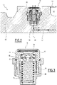
- the non-return member 31 is formed by a non-return valve.
- It comprises a hollow base body 70, mounted in the orifice 29, an insert 72 partially closing the hollow base body 70, defining with the base body 70, a through passage 75 for the circulation of liquid.
- the non-return member 31 comprises a shut-off valve 74, movably mounted in the circulation passage 75 between a closed position of the passage 75, visible on the picture 3 , and an opening position of the passage 75, and a calibrated spring 76 adapted to permanently urge the valve 74 towards its closed position.
- the insert 72 defines a seat 78 protruding into the passage 75 for sealingly seating the valve 74 in the closed position.
- valve 74 is hollow. It has an interior cavity 80 and through openings 82 for the passage of liquid opening into the interior cavity 80.
- valve 74 In the closed position, the valve 74 bears on an inner surface of the seat 78 and seals off the passage 75.
- the valve 74 is held against the seat 78 by the spring 76 as long as the pressure difference between the exterior of the orifice 29 and the interior volume 15 is less than the given threshold value.
- the non-return member 31 is then in its configuration for preventing the passage of fluid.
- the valve moves away from the seat 78, allowing the passage of liquid from the exterior to the interior volume 15 through the passage 75 and the valve 74.
- the non-return member 31 is then in its fluid passage configuration.
- the threshold value depends on the stiffness of the spring 76. This threshold value is for example greater than 0.1 barg and is in particular between 0.2 barg and 10 barg. In this example, the threshold value is between 3 barg and 6 barg.
- the threshold value is chosen to be greater than the maximum variation in pressure undergone by the pipe 10 at the level of the orifice 29 during the movements of the pipe 10 in the body of water, once the pipe 10 has been installed, during the normal operation of the fluid exploitation installation.
- the threshold value can be set at 4 barg or at 5 barg by choosing a spring 76 of appropriate stiffness.
- the conduit 10 is provided after its manufacture, keeping each orifice 29 unobstructed.
- the outer annular space 28 is then advantageously devoid of liquid.
- the pressure in the outer annular space 28 is equal to the outer atmospheric pressure.
- a non-return device 31 For each orifice 29, a non-return device 31 is provided. The proper functioning of the non-return device 31 is tested by a protocol of successive openings and closings of the valve 74 at atmospheric pressure and possibly under conditions simulating immersion in the open sea.
- the non-return device 31 is mounted in the orifice 29.
- This assembly can be carried out in the manufacturing plant of the pipe 10, but also later, on the laying vessel, for example when the tip 14 is accessible just before its immersion in the body of water.
- the pressure applied outside the valve 74 is substantially equal to atmospheric pressure, so that the pressure difference between the outside of the non-return member 31 and the interior volume 15 is less than the threshold value.
- the non-return member 31 is maintained at rest in its fluid passage prevention configuration.
- the passage of fluid from the interior volume 15 to the exterior is prevented by the valve 74 placed in internal support on the seat 78.
- valve 74 moves inwards towards its open position, against the force generated by the spring 76.
- the non-return member 31 then passes into its fluid passage configuration.
- Water under pressure is then driven into the orifice 29, through the non-return device 31, then through the channel 60 to the outer annular space 28.
- the interior volume 15 is therefore at least partially flooded by a liquid, here by the water in which the pipe 10 is immersed.
- the pressure difference between the pressure of the water at the level of the orifice 29 and the pressure which prevails in the interior volume 15 therefore decreases and falls below the threshold value.
- the non-return member 31 then spontaneously resumes its configuration for preventing the passage of fluid.
- the water introduced into the interior volume 15 is therefore confined in a sealed manner in this interior volume 15, here between the outer sheath 22 and the intermediate sheath 24.
- the non-return member 31 is designed so that the threshold value is greater than the maximum pressure variation outside the orifice 29 during the movements of the orifice 29. Once the pipe 10 is place, the non-return member 31 therefore remains permanently in its configuration for preventing the passage of fluid.
- the liquid present in the outer annular space 28 therefore remains confined and is not renewed.
- the oxygen present in this liquid and/or in the gas is rapidly consumed, as are the hydrogen sulphide molecules present, given the large metallic mass of the armor layers 34, 36, which greatly limits the phenomenon of corrosion of the latter.
- the pipe 10 according to the invention and its installation method therefore ensure an adequate service life for the pipe 10, at a lower cost, since it is not necessary to considerably increase the thickness of the intermediate sheath 24 , nor to provide armor layers 34, 36 that are particularly resistant to corrosion.
- the method according to the invention is implemented in a simple manner, by providing a non-return member 31 suitably calibrated, to allow a single flooding of the annular space 28, and prevent the renewal of the liquid introduced into the annular space 28.
- the non-return member 31 is advantageously arranged in an orifice 29 already provided in the end piece 14, which does not require modifying the design of the pipe 10 and/or requalifying it.
- a non-return device 31 is not mounted in each of the orifices 29 provided in the arch 50 of the end piece 14.
- a non-return device 31 may be mounted in certain orifices 29 while the other orifices 29 can be equipped with another type of non-return device.
- This other type of non-return member is, for example, a one-way gas evacuation valve.
- a valve is capable of permanently allowing the passage of gas through the orifices 29 in the direction going from the interior volume 15 to the exterior as soon as the pressure difference between the interior volume 15 and the exterior is greater than a predefined threshold value and for which the pressure of the gases accumulated in the interior volume becomes too great.
- a second pipe 10 according to the invention differs from the first pipe 10 in that it further comprises signaling and/or treatment means capable of being flooded by the liquid penetrating into the orifice 29.
- the signaling and/or treatment means can be in the form of a cartridge 90.
- the cartridge 90 being adapted to contain the signaling agent and/or the treatment agent.
- the cartridge 90 is advantageously placed on a liquid passage path between the orifice 29 and the interior volume 15, for example at the bottom 66 of the orifice 29, under the non-return member 31 and/or in the channel 60 .
- the liquid passes through the cartridge 90 and conveys the signaling and/or treatment agent to the outer annular space 28.
- the signaling agent and/or the treatment agent can be in the form of a liquid or in the form of a powder.
- the signaling agent is for example an ink containing a dye making it possible to visually detect the presence of a leak through the outer sheath 22.
- the treatment agent is advantageously a protective liquid comprising for example a glycol, in particular mono ethylene glycol , the protective liquid advantageously comprising an alcohol.
- the protective liquid may contain a corrosion inhibitor capable of trapping oxygen and/or hydrogen sulphide.
- a third pipe 10 according to the invention is illustrated by the figure 6 . Unlike line 10 shown in figure 1 , this pipe 10 has no intermediate sheath 24. The third pipe 10 therefore comprises a single annular space 26 defined between the pressure sheath 20 and the outer sheath 22.
- the internal tensile armor layers 34, 36 bear radially on the pressure sheath 20.
- Each orifice 29 is connected to the annular space 26 via the channel 60 to allow at least partial flooding of the annular space 26 during the immersion of the pipe 10, without renewal of the liquid introduced into the annular space 26, as previously described.
- the method for installing the third pipe 10 is also similar to that of the first pipe 10.
- a fourth pipe 10 according to the invention is illustrated by the figure 7 .
- this pipe 10 comprises cables 94 for transporting electrical power, capable of emitting heat.
- the cables 94 are arranged in an outer annular space 28, outside an intermediate sheath 24.
- This type of pipe is a multifunction integrated production line (or IPB for "Integrated Production Bundle" in English).
- the orifice 29 is connected to the outer annular space 28 containing the cables 94, to allow at least partial flooding of this annular space 28 during the introduction of the pipe 10 into the body of water, without renewal. liquid introduced into the annular space 28.
- the method for installing this pipe 10 is also similar to that of the pipe 10 visible on the figure 1 .
- the at least partial flooding of the interior volume 15 of the pipe 10 is carried out before the immersion of the pipe 10 in the body of water, for example in the laying vessel.
- the pipe 10 is then filled with a pressurized liquid to temporarily open the non-return device(s) 31 and thus allow at least partial flooding of the interior volume 15.
- the liquid introduced into the pipe 10 may be different from the water present in the body of water.
- This liquid is for example deaerated water, a glycol or another liquid with additives, as described above.
- the non-return member 31 is replaced by a valve that can be operated manually or remotely or even a valve that can be operated using a remote-controlled vehicle between the fluid passage configuration through the orifice 29, from the outside towards the annular space 26, and a configuration preventing the passage of fluid through the orifice 29.
- valve is initially placed in the fluid passage configuration. As described above, this allows at least partial flooding of the annular space 26 by the liquid present outside the pipe 10.
- the valve is operated manually, for example by a diver, or remotely controlled by sending an acoustic signal.
- the valve is maneuvered by a remotely operated vehicle (“Remotely Operated Vehicle” or “ROV) to pass it into the configuration for preventing the passage of fluid and thus confine the liquid present in the annular space 26, by preventing the penetration additional fluid in this space 26.
- ROV Remote Operated Vehicle
- a treatment and/or protection agent can be introduced into the annular space 26 when it is flooded.
- annular space 26 can be filled during the descent of the pipe 10 into the body of water, or alternatively, before its introduction into the body of water, on land or on the laying vessel. .
- the annular space 26 of the pipe 10 is pre-filled almost entirely before its immersion with a deaerated fluid having a very low oxygen concentration.
- the fluid is, for example, stagnant water, deaerated sea water, a "magic fluid" type lubricant obtained by mixing a glycol such as MonoEthylene Glycol (MEG) with an alcohol such as methanol, the mixture possibly containing other additives such as a corrosion inhibitor.
- MEG MonoEthylene Glycol
- the quantity of seawater introduced into the annular space 26 of the pipe 10 during its immersion is very low compared to the quantity of the fluid introduced during the pre-filling step, for example less than 10% by volume.
Claims (6)
- Verfahren zum Anbringen einer flexiblen Leitung, umfassend einen äußeren Mantel (22), der ein inneres Volumen (15) begrenzt, einen undurchlässigen Mantel (20; 24), der in dem inneren Volumen (15) an dem äußeren Mantel (22) angeordnet ist, wobei mindestens eine Öffnung (29) fluidisch mit einem Ringraum (26; 28) verbunden ist, der zwischen dem undurchlässigen Mantel (20; 24) und dem äußeren Mantel (22) definiert ist; umfassend die folgenden Schritte:- Einleiten einer Flüssigkeit in die flexible Leitung;- zumindest teilweises Fluten des Ringraums (26; 28) zwischen dem undurchlässigen Mantel (20; 24) und dem äußeren Mantel (22), ohne das Volumen, das sich im Innern des undurchlässigen Mantels (20; 24) befindet, durch die mindestens eine Öffnung (29), die in der flexiblen Leitung angeordnet ist, mit der Flüssigkeit zu fluten;die flexible Leitung umfassend mindestens ein längliches Verstärkungselement (44) und/oder ein längliches Element (94) zum Transport von elektrischer Leistung und/oder Informationen, das in dem Ringraum (26; 28) zwischen dem undurchlässigen Mantel (20; 24) und dem äußeren Mantel (22) angeordnet ist
dadurch gekennzeichnet, dass das Verfahren einen Schritt eines Schließens der oder jeder Öffnung (29) nach dem Schritt eines Flutens umfasst. - Verfahren nach Anspruch 1, wobei die flexible Leitung ein Rückschlagorgan (31) aufweist, das in der Öffnung (29) angeordnet ist und den Durchgang von Flüssigkeit aus dem inneren Volumen (15) nach außen verhindert, wobei das Rückschlagorgan (31) eine Konfiguration für den Durchgang von Flüssigkeit durch die Öffnung (29) von außen in das innere Volumen (15) annimmt, wenn die Druckdifferenz zwischen der Flüssigkeit außerhalb des Rückschlagorgans (31) und dem inneren Volumen (15) größer ist als ein gegebener Schwellenwert, der während des Schritts eines Flutens nicht Null ist, wobei das Rückschlagorgan (31) spontan in eine Konfiguration übergeht, die den Durchgang von Fluid durch die Öffnung (29) verhindert, wenn die Druckdifferenz zwischen der Flüssigkeit außerhalb des Rückschlagorgans (31) und dem inneren Volumen (15) nach dem Schritt eines Flutens kleiner ist als der gegebene Schwellenwert.
- Verfahren nach Anspruch 2, wobei nach dem Schritt eines Schließens das Rückschlagorgan (31) bei Änderungen der Tiefe der Öffnung (29) in der Flüssigkeit in seiner geschlossenen Konfiguration bleibt.
- Verfahren nach einem der Ansprüche 2 oder 3, wobei der Schwellenwert größer ist als 0,1 bar (g) ist und insbesondere zwischen 0,2 bar (g) und 10 bar (g) liegt.
- Verfahren nach Anspruch 1, wobei die Leitung ein manuell bedienbares Ventil, ein durch Senden eines akustischen Signals ferngesteuertes Ventil oder ein von einem ferngesteuerten Fahrzeug bedienbares Ventil zwischen einer Konfiguration für einen Durchgang von Fluid durch die Öffnung (29) von außen in das innere Volumen (15), und einer Konfiguration zum Verhindern eines Durchgangs von Fluid durch die Öffnung (29) umfasst, wobei das Ventil während des Schritts eines Flutens in der Fluiddurchgangskonfiguration ist, das Verfahren umfassend einen Schritt eines Bedienens des Ventils in die Konfiguration zum Verhindern des Durchgangs von Fluid nach dem Schritt eines Flutens.
- Verfahren nach einem der vorherigen Ansprüche, wobei die Flüssigkeit ein Wasserkörper ist, in dem die flexible Leitung installiert ist, der Schritt eines Flutens umfassend das Einleiten von Wasser aus dem Wasserkörper in das innere Volumen (15).
Applications Claiming Priority (2)
| Application Number | Priority Date | Filing Date | Title |
|---|---|---|---|
| FR1461248A FR3028912B1 (fr) | 2014-11-20 | 2014-11-20 | Procede de mise en place d'une ligne flexible comportant une gaine externe delimitant un volume interieur et ligne flexible associee |
| PCT/EP2015/077137 WO2016079253A1 (fr) | 2014-11-20 | 2015-11-19 | Procédé de mise en place d'une ligne flexible comportant une gaine externe délimitant un volume intérieur et ligne flexible associée |
Publications (2)
| Publication Number | Publication Date |
|---|---|
| EP3221625A1 EP3221625A1 (de) | 2017-09-27 |
| EP3221625B1 true EP3221625B1 (de) | 2022-06-29 |
Family
ID=52589520
Family Applications (1)
| Application Number | Title | Priority Date | Filing Date |
|---|---|---|---|
| EP15801718.6A Active EP3221625B1 (de) | 2014-11-20 | 2015-11-19 | Verfahren zum installieren einer flexiblen leitung mit einer aussenhülle zur abgrenzung eines innenraums |
Country Status (5)
| Country | Link |
|---|---|
| EP (1) | EP3221625B1 (de) |
| BR (1) | BR112017010199B1 (de) |
| DK (1) | DK3221625T3 (de) |
| FR (1) | FR3028912B1 (de) |
| WO (1) | WO2016079253A1 (de) |
Families Citing this family (5)
| Publication number | Priority date | Publication date | Assignee | Title |
|---|---|---|---|---|
| FR3031159B1 (fr) * | 2014-12-31 | 2017-02-10 | Technip France | Ligne destinee a etre immergee dans une etendue d'eau et procede de mise en place associe |
| FR3047292B1 (fr) * | 2016-01-28 | 2018-03-02 | Technip France | Ligne flexible a annulaire inonde |
| FR3067438B1 (fr) * | 2017-06-09 | 2019-07-26 | Technip France | Embout de connexion d'une ligne flexible, ligne flexible et procede associes |
| WO2020099228A1 (en) * | 2018-11-13 | 2020-05-22 | National Oilwell Varco Denmark I/S | A method for flushing a flexible pipe and an assembly of a flexible pipe and an end-fitting |
| GB201913740D0 (en) * | 2019-09-24 | 2019-11-06 | Ge Oil & Gas Uk Ltd | End fitting apparatus and method |
Citations (6)
| Publication number | Priority date | Publication date | Assignee | Title |
|---|---|---|---|---|
| FR721430A (fr) * | 1930-11-12 | 1932-03-03 | Tuyau souple | |
| FR2326229A1 (fr) * | 1975-10-03 | 1977-04-29 | Grihangne Andre | Agencement de parois minces constituant l'enveloppe de revolution d'un conduit d'aspiration ou d'un reservoir en depression par rapport au milieu exterieur |
| US4778306A (en) * | 1985-12-06 | 1988-10-18 | Snamprogetti S.P.A. | Method for launching from the mainland large-size submarine pipelines |
| WO2000011387A1 (en) * | 1998-08-20 | 2000-03-02 | Bogey Venlo B.V. | System for controlled lowering of a tube or cable |
| WO2000017479A1 (en) * | 1998-09-24 | 2000-03-30 | Nkt Flexibles A/S | A reinforced flexible tubular pipe with conveying back of leak fluid |
| EP2084444A2 (de) * | 2006-10-30 | 2009-08-05 | Wellstream International Limited | Prüfen und entlüften eines rohrringraums |
Family Cites Families (2)
| Publication number | Priority date | Publication date | Assignee | Title |
|---|---|---|---|---|
| WO2012092931A1 (en) * | 2011-01-06 | 2012-07-12 | National Oilwell Varco Denmark I/S | An unbonded flexible pipe |
| GB201111371D0 (en) * | 2011-07-04 | 2011-08-17 | Wellstream Int Ltd | Gas venting |
-
2014
- 2014-11-20 FR FR1461248A patent/FR3028912B1/fr active Active
-
2015
- 2015-11-19 WO PCT/EP2015/077137 patent/WO2016079253A1/fr active Application Filing
- 2015-11-19 BR BR112017010199-8A patent/BR112017010199B1/pt active IP Right Grant
- 2015-11-19 DK DK15801718.6T patent/DK3221625T3/da active
- 2015-11-19 EP EP15801718.6A patent/EP3221625B1/de active Active
Patent Citations (6)
| Publication number | Priority date | Publication date | Assignee | Title |
|---|---|---|---|---|
| FR721430A (fr) * | 1930-11-12 | 1932-03-03 | Tuyau souple | |
| FR2326229A1 (fr) * | 1975-10-03 | 1977-04-29 | Grihangne Andre | Agencement de parois minces constituant l'enveloppe de revolution d'un conduit d'aspiration ou d'un reservoir en depression par rapport au milieu exterieur |
| US4778306A (en) * | 1985-12-06 | 1988-10-18 | Snamprogetti S.P.A. | Method for launching from the mainland large-size submarine pipelines |
| WO2000011387A1 (en) * | 1998-08-20 | 2000-03-02 | Bogey Venlo B.V. | System for controlled lowering of a tube or cable |
| WO2000017479A1 (en) * | 1998-09-24 | 2000-03-30 | Nkt Flexibles A/S | A reinforced flexible tubular pipe with conveying back of leak fluid |
| EP2084444A2 (de) * | 2006-10-30 | 2009-08-05 | Wellstream International Limited | Prüfen und entlüften eines rohrringraums |
Also Published As
| Publication number | Publication date |
|---|---|
| EP3221625A1 (de) | 2017-09-27 |
| BR112017010199A2 (pt) | 2018-02-06 |
| DK3221625T3 (da) | 2022-09-19 |
| BR112017010199B1 (pt) | 2021-05-18 |
| FR3028912B1 (fr) | 2016-12-30 |
| WO2016079253A1 (fr) | 2016-05-26 |
| FR3028912A1 (fr) | 2016-05-27 |
Similar Documents
| Publication | Publication Date | Title |
|---|---|---|
| EP3221625B1 (de) | Verfahren zum installieren einer flexiblen leitung mit einer aussenhülle zur abgrenzung eines innenraums | |
| EP3014157B1 (de) | Schlauch und verfahren dafür | |
| EP3469244B1 (de) | Verbindungsendstück für eine flexible leitung und zugehörige flexible leitung und verfahren | |
| CA2684770C (fr) | Conduite tubulaire flexible pour le transport d'hydrocarbures gazeux | |
| WO2018114418A1 (fr) | Conduite flexible de transport de fluide petrolier comprenant une barriere contre la diffusion | |
| FR3084130A1 (fr) | Conduite flexible pour le transport d'un fluide petrolier et/ou gazier destinee a etre immergee au sein d'une etendue d'eau | |
| EP3286474A1 (de) | Verfahren zur herstellung einer dichtung in einer spitze eines flexiblen schlauchs mit einer druckhülle | |
| FR3064711A1 (fr) | Conduite flexible avec nappes d'armures metalliques et nappes d'armures composites | |
| EP3004709B1 (de) | Flexible leitung zur förderung eines fluids, verwendung davon und verfahren | |
| EP0937932A2 (de) | Flexible Rohrleitung für Steigrohrleitung für Ölgewinnung aus dem Meer | |
| EP1608904B1 (de) | Flexible rohrleitung zum transport eines fluids | |
| EP1561061B1 (de) | Flexible röhrenförmige leitung zum fluidtransport | |
| EP3123067B1 (de) | Biegsames rohr für den transport von flüssigkeiten, zugehörige fertigung und bestimmungsverfahren | |
| EP3408571B1 (de) | Flexible leitung mit geflutetem ringförmigem raum | |
| FR3067438B1 (fr) | Embout de connexion d'une ligne flexible, ligne flexible et procede associes | |
| EP3240967B1 (de) | Leitung zum untertauchen in einen wasserkörper und entsprechendes verfahren zur platzierung | |
| EP3768506B1 (de) | Leitung zum untertauchen in einen wasserkörper und entsprechendes verfahren zur herstellung | |
| FR3104667A1 (fr) | Conduite flexible sous-marine comprenant une couche comprenant du polyméthylpentène |
Legal Events
| Date | Code | Title | Description |
|---|---|---|---|
| STAA | Information on the status of an ep patent application or granted ep patent |
Free format text: STATUS: THE INTERNATIONAL PUBLICATION HAS BEEN MADE |
|
| PUAI | Public reference made under article 153(3) epc to a published international application that has entered the european phase |
Free format text: ORIGINAL CODE: 0009012 |
|
| STAA | Information on the status of an ep patent application or granted ep patent |
Free format text: STATUS: REQUEST FOR EXAMINATION WAS MADE |
|
| 17P | Request for examination filed |
Effective date: 20170515 |
|
| AK | Designated contracting states |
Kind code of ref document: A1 Designated state(s): AL AT BE BG CH CY CZ DE DK EE ES FI FR GB GR HR HU IE IS IT LI LT LU LV MC MK MT NL NO PL PT RO RS SE SI SK SM TR |
|
| AX | Request for extension of the european patent |
Extension state: BA ME |
|
| DAV | Request for validation of the european patent (deleted) | ||
| DAX | Request for extension of the european patent (deleted) | ||
| STAA | Information on the status of an ep patent application or granted ep patent |
Free format text: STATUS: EXAMINATION IS IN PROGRESS |
|
| 17Q | First examination report despatched |
Effective date: 20180820 |
|
| RAP1 | Party data changed (applicant data changed or rights of an application transferred) |
Owner name: TECHNIP N-POWER |
|
| STAA | Information on the status of an ep patent application or granted ep patent |
Free format text: STATUS: EXAMINATION IS IN PROGRESS |
|
| GRAP | Despatch of communication of intention to grant a patent |
Free format text: ORIGINAL CODE: EPIDOSNIGR1 |
|
| STAA | Information on the status of an ep patent application or granted ep patent |
Free format text: STATUS: GRANT OF PATENT IS INTENDED |
|
| INTG | Intention to grant announced |
Effective date: 20210930 |
|
| GRAJ | Information related to disapproval of communication of intention to grant by the applicant or resumption of examination proceedings by the epo deleted |
Free format text: ORIGINAL CODE: EPIDOSDIGR1 |
|
| STAA | Information on the status of an ep patent application or granted ep patent |
Free format text: STATUS: EXAMINATION IS IN PROGRESS |
|
| GRAP | Despatch of communication of intention to grant a patent |
Free format text: ORIGINAL CODE: EPIDOSNIGR1 |
|
| STAA | Information on the status of an ep patent application or granted ep patent |
Free format text: STATUS: GRANT OF PATENT IS INTENDED |
|
| INTC | Intention to grant announced (deleted) | ||
| INTG | Intention to grant announced |
Effective date: 20220202 |
|
| GRAS | Grant fee paid |
Free format text: ORIGINAL CODE: EPIDOSNIGR3 |
|
| GRAA | (expected) grant |
Free format text: ORIGINAL CODE: 0009210 |
|
| STAA | Information on the status of an ep patent application or granted ep patent |
Free format text: STATUS: THE PATENT HAS BEEN GRANTED |
|
| AK | Designated contracting states |
Kind code of ref document: B1 Designated state(s): AL AT BE BG CH CY CZ DE DK EE ES FI FR GB GR HR HU IE IS IT LI LT LU LV MC MK MT NL NO PL PT RO RS SE SI SK SM TR |
|
| REG | Reference to a national code |
Ref country code: GB Ref legal event code: FG4D Free format text: NOT ENGLISH |
|
| REG | Reference to a national code |
Ref country code: CH Ref legal event code: EP |
|
| REG | Reference to a national code |
Ref country code: AT Ref legal event code: REF Ref document number: 1501556 Country of ref document: AT Kind code of ref document: T Effective date: 20220715 |
|
| REG | Reference to a national code |
Ref country code: IE Ref legal event code: FG4D Free format text: LANGUAGE OF EP DOCUMENT: FRENCH |
|
| REG | Reference to a national code |
Ref country code: DE Ref legal event code: R096 Ref document number: 602015079677 Country of ref document: DE |
|
| REG | Reference to a national code |
Ref country code: DK Ref legal event code: T3 Effective date: 20220915 |
|
| REG | Reference to a national code |
Ref country code: NO Ref legal event code: T2 Effective date: 20220629 |
|
| REG | Reference to a national code |
Ref country code: LT Ref legal event code: MG9D |
|
| PG25 | Lapsed in a contracting state [announced via postgrant information from national office to epo] |
Ref country code: SE Free format text: LAPSE BECAUSE OF FAILURE TO SUBMIT A TRANSLATION OF THE DESCRIPTION OR TO PAY THE FEE WITHIN THE PRESCRIBED TIME-LIMIT Effective date: 20220629 Ref country code: LT Free format text: LAPSE BECAUSE OF FAILURE TO SUBMIT A TRANSLATION OF THE DESCRIPTION OR TO PAY THE FEE WITHIN THE PRESCRIBED TIME-LIMIT Effective date: 20220629 Ref country code: HR Free format text: LAPSE BECAUSE OF FAILURE TO SUBMIT A TRANSLATION OF THE DESCRIPTION OR TO PAY THE FEE WITHIN THE PRESCRIBED TIME-LIMIT Effective date: 20220629 Ref country code: GR Free format text: LAPSE BECAUSE OF FAILURE TO SUBMIT A TRANSLATION OF THE DESCRIPTION OR TO PAY THE FEE WITHIN THE PRESCRIBED TIME-LIMIT Effective date: 20220930 Ref country code: FI Free format text: LAPSE BECAUSE OF FAILURE TO SUBMIT A TRANSLATION OF THE DESCRIPTION OR TO PAY THE FEE WITHIN THE PRESCRIBED TIME-LIMIT Effective date: 20220629 Ref country code: BG Free format text: LAPSE BECAUSE OF FAILURE TO SUBMIT A TRANSLATION OF THE DESCRIPTION OR TO PAY THE FEE WITHIN THE PRESCRIBED TIME-LIMIT Effective date: 20220929 |
|
| REG | Reference to a national code |
Ref country code: NL Ref legal event code: MP Effective date: 20220629 |
|
| REG | Reference to a national code |
Ref country code: AT Ref legal event code: MK05 Ref document number: 1501556 Country of ref document: AT Kind code of ref document: T Effective date: 20220629 |
|
| PG25 | Lapsed in a contracting state [announced via postgrant information from national office to epo] |
Ref country code: RS Free format text: LAPSE BECAUSE OF FAILURE TO SUBMIT A TRANSLATION OF THE DESCRIPTION OR TO PAY THE FEE WITHIN THE PRESCRIBED TIME-LIMIT Effective date: 20220629 Ref country code: LV Free format text: LAPSE BECAUSE OF FAILURE TO SUBMIT A TRANSLATION OF THE DESCRIPTION OR TO PAY THE FEE WITHIN THE PRESCRIBED TIME-LIMIT Effective date: 20220629 |
|
| PG25 | Lapsed in a contracting state [announced via postgrant information from national office to epo] |
Ref country code: NL Free format text: LAPSE BECAUSE OF FAILURE TO SUBMIT A TRANSLATION OF THE DESCRIPTION OR TO PAY THE FEE WITHIN THE PRESCRIBED TIME-LIMIT Effective date: 20220629 |
|
| PG25 | Lapsed in a contracting state [announced via postgrant information from national office to epo] |
Ref country code: SM Free format text: LAPSE BECAUSE OF FAILURE TO SUBMIT A TRANSLATION OF THE DESCRIPTION OR TO PAY THE FEE WITHIN THE PRESCRIBED TIME-LIMIT Effective date: 20220629 Ref country code: SK Free format text: LAPSE BECAUSE OF FAILURE TO SUBMIT A TRANSLATION OF THE DESCRIPTION OR TO PAY THE FEE WITHIN THE PRESCRIBED TIME-LIMIT Effective date: 20220629 Ref country code: RO Free format text: LAPSE BECAUSE OF FAILURE TO SUBMIT A TRANSLATION OF THE DESCRIPTION OR TO PAY THE FEE WITHIN THE PRESCRIBED TIME-LIMIT Effective date: 20220629 Ref country code: PT Free format text: LAPSE BECAUSE OF FAILURE TO SUBMIT A TRANSLATION OF THE DESCRIPTION OR TO PAY THE FEE WITHIN THE PRESCRIBED TIME-LIMIT Effective date: 20221031 Ref country code: ES Free format text: LAPSE BECAUSE OF FAILURE TO SUBMIT A TRANSLATION OF THE DESCRIPTION OR TO PAY THE FEE WITHIN THE PRESCRIBED TIME-LIMIT Effective date: 20220629 Ref country code: EE Free format text: LAPSE BECAUSE OF FAILURE TO SUBMIT A TRANSLATION OF THE DESCRIPTION OR TO PAY THE FEE WITHIN THE PRESCRIBED TIME-LIMIT Effective date: 20220629 Ref country code: AT Free format text: LAPSE BECAUSE OF FAILURE TO SUBMIT A TRANSLATION OF THE DESCRIPTION OR TO PAY THE FEE WITHIN THE PRESCRIBED TIME-LIMIT Effective date: 20220629 |
|
| PG25 | Lapsed in a contracting state [announced via postgrant information from national office to epo] |
Ref country code: PL Free format text: LAPSE BECAUSE OF FAILURE TO SUBMIT A TRANSLATION OF THE DESCRIPTION OR TO PAY THE FEE WITHIN THE PRESCRIBED TIME-LIMIT Effective date: 20220629 Ref country code: IS Free format text: LAPSE BECAUSE OF FAILURE TO SUBMIT A TRANSLATION OF THE DESCRIPTION OR TO PAY THE FEE WITHIN THE PRESCRIBED TIME-LIMIT Effective date: 20221029 |
|
| REG | Reference to a national code |
Ref country code: DE Ref legal event code: R097 Ref document number: 602015079677 Country of ref document: DE |
|
| PG25 | Lapsed in a contracting state [announced via postgrant information from national office to epo] |
Ref country code: AL Free format text: LAPSE BECAUSE OF FAILURE TO SUBMIT A TRANSLATION OF THE DESCRIPTION OR TO PAY THE FEE WITHIN THE PRESCRIBED TIME-LIMIT Effective date: 20220629 |
|
| PG25 | Lapsed in a contracting state [announced via postgrant information from national office to epo] |
Ref country code: CZ Free format text: LAPSE BECAUSE OF FAILURE TO SUBMIT A TRANSLATION OF THE DESCRIPTION OR TO PAY THE FEE WITHIN THE PRESCRIBED TIME-LIMIT Effective date: 20220629 |
|
| PLBE | No opposition filed within time limit |
Free format text: ORIGINAL CODE: 0009261 |
|
| STAA | Information on the status of an ep patent application or granted ep patent |
Free format text: STATUS: NO OPPOSITION FILED WITHIN TIME LIMIT |
|
| REG | Reference to a national code |
Ref country code: DE Ref legal event code: R119 Ref document number: 602015079677 Country of ref document: DE |
|
| 26N | No opposition filed |
Effective date: 20230330 |
|
| P01 | Opt-out of the competence of the unified patent court (upc) registered |
Effective date: 20230516 |
|
| PG25 | Lapsed in a contracting state [announced via postgrant information from national office to epo] |
Ref country code: MC Free format text: LAPSE BECAUSE OF FAILURE TO SUBMIT A TRANSLATION OF THE DESCRIPTION OR TO PAY THE FEE WITHIN THE PRESCRIBED TIME-LIMIT Effective date: 20220629 |
|
| REG | Reference to a national code |
Ref country code: CH Ref legal event code: PL |
|
| REG | Reference to a national code |
Ref country code: BE Ref legal event code: MM Effective date: 20221130 |
|
| PG25 | Lapsed in a contracting state [announced via postgrant information from national office to epo] |
Ref country code: LI Free format text: LAPSE BECAUSE OF NON-PAYMENT OF DUE FEES Effective date: 20221130 Ref country code: CH Free format text: LAPSE BECAUSE OF NON-PAYMENT OF DUE FEES Effective date: 20221130 |
|
| PG25 | Lapsed in a contracting state [announced via postgrant information from national office to epo] |
Ref country code: SI Free format text: LAPSE BECAUSE OF FAILURE TO SUBMIT A TRANSLATION OF THE DESCRIPTION OR TO PAY THE FEE WITHIN THE PRESCRIBED TIME-LIMIT Effective date: 20220629 Ref country code: LU Free format text: LAPSE BECAUSE OF NON-PAYMENT OF DUE FEES Effective date: 20221119 |
|
| PG25 | Lapsed in a contracting state [announced via postgrant information from national office to epo] |
Ref country code: IE Free format text: LAPSE BECAUSE OF NON-PAYMENT OF DUE FEES Effective date: 20221119 Ref country code: DE Free format text: LAPSE BECAUSE OF NON-PAYMENT OF DUE FEES Effective date: 20230601 |
|
| PG25 | Lapsed in a contracting state [announced via postgrant information from national office to epo] |
Ref country code: BE Free format text: LAPSE BECAUSE OF NON-PAYMENT OF DUE FEES Effective date: 20221130 |
|
| PGFP | Annual fee paid to national office [announced via postgrant information from national office to epo] |
Ref country code: GB Payment date: 20231120 Year of fee payment: 9 |
|
| PG25 | Lapsed in a contracting state [announced via postgrant information from national office to epo] |
Ref country code: IT Free format text: LAPSE BECAUSE OF FAILURE TO SUBMIT A TRANSLATION OF THE DESCRIPTION OR TO PAY THE FEE WITHIN THE PRESCRIBED TIME-LIMIT Effective date: 20220629 |
|
| PGFP | Annual fee paid to national office [announced via postgrant information from national office to epo] |
Ref country code: NO Payment date: 20231024 Year of fee payment: 9 Ref country code: FR Payment date: 20231128 Year of fee payment: 9 Ref country code: DK Payment date: 20231025 Year of fee payment: 9 |
|
| PG25 | Lapsed in a contracting state [announced via postgrant information from national office to epo] |
Ref country code: HU Free format text: LAPSE BECAUSE OF FAILURE TO SUBMIT A TRANSLATION OF THE DESCRIPTION OR TO PAY THE FEE WITHIN THE PRESCRIBED TIME-LIMIT; INVALID AB INITIO Effective date: 20151119 |
|
| PG25 | Lapsed in a contracting state [announced via postgrant information from national office to epo] |
Ref country code: CY Free format text: LAPSE BECAUSE OF FAILURE TO SUBMIT A TRANSLATION OF THE DESCRIPTION OR TO PAY THE FEE WITHIN THE PRESCRIBED TIME-LIMIT Effective date: 20220629 |