EP3220847B1 - Sterile barrier assembly for use in robotic surgical system - Google Patents
Sterile barrier assembly for use in robotic surgical system Download PDFInfo
- Publication number
- EP3220847B1 EP3220847B1 EP15861501.3A EP15861501A EP3220847B1 EP 3220847 B1 EP3220847 B1 EP 3220847B1 EP 15861501 A EP15861501 A EP 15861501A EP 3220847 B1 EP3220847 B1 EP 3220847B1
- Authority
- EP
- European Patent Office
- Prior art keywords
- tab
- sterile
- barrier
- barrier membrane
- instrument
- Prior art date
- Legal status (The legal status is an assumption and is not a legal conclusion. Google has not performed a legal analysis and makes no representation as to the accuracy of the status listed.)
- Active
Links
- 230000004888 barrier function Effects 0.000 title claims description 123
- 239000012528 membrane Substances 0.000 claims description 74
- 230000008878 coupling Effects 0.000 claims description 7
- 238000010168 coupling process Methods 0.000 claims description 7
- 238000005859 coupling reaction Methods 0.000 claims description 7
- 239000000463 material Substances 0.000 claims description 6
- -1 polyethylene Polymers 0.000 claims description 5
- 239000013013 elastic material Substances 0.000 claims description 4
- 238000000638 solvent extraction Methods 0.000 claims description 4
- 239000004698 Polyethylene Substances 0.000 claims description 3
- 229920000573 polyethylene Polymers 0.000 claims description 3
- 229920000515 polycarbonate Polymers 0.000 claims description 2
- 239000004417 polycarbonate Substances 0.000 claims description 2
- 238000005192 partition Methods 0.000 claims 1
- 238000000034 method Methods 0.000 description 4
- 230000036512 infertility Effects 0.000 description 2
- 238000013507 mapping Methods 0.000 description 2
- 239000004033 plastic Substances 0.000 description 2
- 229920003023 plastic Polymers 0.000 description 2
- 230000001954 sterilising effect Effects 0.000 description 2
- 229920000459 Nitrile rubber Polymers 0.000 description 1
- 238000010276 construction Methods 0.000 description 1
- 229920001971 elastomer Polymers 0.000 description 1
- 239000003292 glue Substances 0.000 description 1
- 238000009434 installation Methods 0.000 description 1
- 229920000126 latex Polymers 0.000 description 1
- 239000004816 latex Substances 0.000 description 1
- 229920001084 poly(chloroprene) Polymers 0.000 description 1
- 229920002379 silicone rubber Polymers 0.000 description 1
- 239000004945 silicone rubber Substances 0.000 description 1
- 238000004659 sterilization and disinfection Methods 0.000 description 1
- 238000006467 substitution reaction Methods 0.000 description 1
- 125000000391 vinyl group Chemical group [H]C([*])=C([H])[H] 0.000 description 1
- 229920002554 vinyl polymer Polymers 0.000 description 1
Images


Classifications
-
- A—HUMAN NECESSITIES
- A61—MEDICAL OR VETERINARY SCIENCE; HYGIENE
- A61B—DIAGNOSIS; SURGERY; IDENTIFICATION
- A61B46/00—Surgical drapes
- A61B46/10—Surgical drapes specially adapted for instruments, e.g. microscopes
-
- A—HUMAN NECESSITIES
- A61—MEDICAL OR VETERINARY SCIENCE; HYGIENE
- A61B—DIAGNOSIS; SURGERY; IDENTIFICATION
- A61B34/00—Computer-aided surgery; Manipulators or robots specially adapted for use in surgery
- A61B34/30—Surgical robots
-
- A—HUMAN NECESSITIES
- A61—MEDICAL OR VETERINARY SCIENCE; HYGIENE
- A61B—DIAGNOSIS; SURGERY; IDENTIFICATION
- A61B46/00—Surgical drapes
Definitions
- Robotic surgical systems have been used in minimally invasive medical procedures.
- Some robotic surgical systems include a console supporting a robot arm and a surgical instrument that is mounted to the robot arm.
- the robot arm provides mechanical power to the surgical instrument for its operation and movement.
- Each robot arm may include an instrument drive unit that is operatively connected to the surgical instrument.
- surgical instruments Prior to or during use of the robotic system, surgical instruments are selected and connected to the instrument drive units of each robot arm. For proper installation to be completed, certain connecting features of the surgical instrument must be matingly engaged to corresponding connecting features of the instrument drive unit. Once these features are matingly engaged, the instrument drive unit can drive the actuation of the surgical instrument.
- sterile plastic or rubber covers so-called sterile barriers, are generally pulled over the (inherently non-sterile) device, or are used to give the device a sterile covering.
- WO 2014/005689 A2 discloses a robot-guided surgical instrument with a drive module and an instrument shaft of such an instrument, a manipulator assembly having at least one such instrument, which is guided by a manipulator, and a method and a guidance means for guiding such an instrument.
- a sterile barrier encases a drive unit and is disposed between this drive unit and the instrument shaft. There is a need for a sterile barrier assembly that provides for an easier removal and attachment to a surgical instrument. Additional relevant sterile barriers are disclosed in US 2009/248039 A1 and WO 2010/121117 A1 .
- a sterile barrier assembly as defined in claim 1 annexed hereto.
- the barrier assembly includes a base member, a securing member and a barrier membrane securely interposed between the base member and the securing member, the base member and securing member defining a cavity with the barrier membrane partitioning the cavity into a sterile and a non-sterile side; a tab having a first and a second portion with the barrier member interposed between the first and second portions of the tab, the tab being slideable along a sliding path in a cavity of the sterile barrier assembly.
- the barrier membrane at least partially moves with the tab as the tab slides along the sliding path.
- a first portion of the tab interfaces with an output of a surgical tool driving unit on the non-sterile side.
- a second portion of the tab interfaces with a tool driver of a surgical tool on the sterile side.
- the barrier membrane is interposed between the first and the second portions of the tab.
- the barrier membrane may be adjacent the first portion of the tab and the barrier membrane may contour around at least one of the first portion of the tab and the surgical tool driving unit output as the first portion of the tab interfaces with the surgical tool driving unit output.
- the barrier membrane may be adjacent the second portion of the tab and the barrier membrane may contour around at least one of the second portion of the tab and the tool driver as the second portion of the tab interfaces with the tool driver.
- the surgical tool driving unit output may move rotationally while the tab and the tool driver move translationally, and the tab may impart translational movement to the tool driver from the rotational output of the driving unit.
- the sterile barrier assembly includes an elongated element attached to the tab and extending into a longitudinal channel in the sterile barrier assembly.
- the tab and elongated element slide in a longitudinal direction of the channel that is collinear with the barrier membrane.
- the tab may slide longitudinally along a guide rail in the sterile barrier assembly.
- the barrier membrane may be formed of an elastic material.
- the barrier membrane may be formed of an inelastic material.
- the barrier membrane may include slack in the inelastic material that tautens as the tab slides in at least one direction.
- the barrier membrane may be hermetically sealed to at least one component of the sterile barrier assembly.
- a robotic surgical system including a sterile instrument, a manipulator assembly, a non- sterile drive unit, and a sterile barrier assembly in accordance with the invention.
- the sterile instrument has a surgical tool manipulated by a plurality of tool drivers in a plurality of directions.
- the manipulator assembly has a linkage coupling a base to an instrument holder supporting the sterile instrument. The linkage is movable in a plurality of degrees of freedom.
- the non-sterile drive unit includes a plurality of driven outputs.
- the sterile barrier has a barrier membrane partitioning the sterile barrier into a sterile side coupled to the sterile instrument and a non-sterile side coupled to the non-sterile drive unit.
- the barrier membrane at least partially moves with a plurality of tabs in the sterile barrier as the tabs slide along respective tab sliding paths. The tabs couple the driven outputs of the drive unit to the tool drivers of the sterile instrument.
- the tabs include a first portion coupling to the driven outputs of the drive unit and a second portion coupling to the tool drivers of the instrument.
- the barrier membrane is interposed between the first and second portions. At least one portion of each tab may be slidingly attached to at least one guide rail. The at least one guide rail may define the respective tab sliding paths for each tab. An axial translation of each tab along the at least one guide rail may impart a translational movement to the respective tool drivers of the instrument.
- the barrier membrane may be formed of polyethylene or polycarbonate.
- Also disclosed herein but not forming part of the invention is a method including actuating a driven output of an instrument drive unit detachably coupled to a non-sterile side of a sterile barrier having a barrier membrane partitioning the non-sterile side of the sterile barrier from a sterile side; responsive to the actuating, sliding a tab in the sterile barrier detachably coupled to the driven output along a translational tab slide path in the sterile barrier; at least partially moving the barrier membrane as the tab slides along the translational tab slide path; responsive to the sliding of the tab, translationally moving a driver of a sterile instrument detachably coupled to the sliding tab on the sterile side of the sterile barrier; and manipulating a surgical tool connected to the driver as the driver is translationally moved.
- distal as is conventional, will refer to that portion of the instrument, apparatus, device or component thereof which is farther from the user while, the term “proximal,” will refer to that portion of the instrument, apparatus, device or component thereof which is closer to the user.
- proximal will refer to that portion of the instrument, apparatus, device or component thereof which is closer to the user.
- Robotic surgical system 10 including a sterile barrier assembly 100 ( FIG. 5 ) in accordance with an embodiment of the present disclosure.
- Robotic surgical system 10 generally includes displays 12, a mapping system 14, an input control system 16, an electronic control system 18, a manipulator assembly 20, and a manipulator assembly support structure 22.
- mapping system 14 determines a position and orientation of a sensor-equipped surgical instrument 44.
- Input control system 16 controls actuation of surgical instrument 44 through user input.
- Electronic control system 18 translates user input from input control system 16 into actuation control signals.
- manipulator assembly 20 actuates surgical instrument 44.
- Manipulator assembly 20 includes a translation assembly 32 and a drive assembly 34 mounted on translation assembly 32.
- Drive assembly 34 is configured to actuate the surgical instrument 44 in response to the actuation control signals from electronic control system 18.
- Manipulator assembly support structure 22 is utilized to position manipulator assembly 20 in proximity to a patient "P".
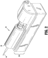
- drive assembly 34 includes an instrument drive unit (“IDU") 38 and a medical device cartridge 36 removably attached to IDU 38.
- Medical device cartridge 36 includes an outer housing 40 ( FIG. 3 ), a base portion 48 ( FIG. 3 ), and a rotatable assembly 42 ( FIG. 4 ) disposed within outer housing 40.
- Rotatable assembly 42 includes surgical instrument 44 operatively coupled thereto.
- Rotatable assembly 42 includes mechanical drive interfaces 64 1, 2 operatively associated with tabs 176 1, 2 ( FIG. 5 ) of sterile barrier assembly 100 ( FIG. 5 ).
- sterile barrier assembly 100 in accordance with an embodiment of the present disclosure is configured to separate a sterile portion of surgical instrument 44 with the non-sterile portion of manipulator assembly 20 ( FIG. 1 ), while enabling motion to pass from IDU 38 ( FIG. 2 ) to surgical instrument 44.
- Sterile barrier assembly 100 includes a base member 102, a securing member 104, a barrier membrane 106 ( FIG. 5 ), actuation rails 112, and tabs 176 1-4 .
- Base member 102 and securing member 104 define a cavity 108 dimensioned to receive actuation rails 112 and tabs 176 1-4 operatively mounted on actuation rails 112.
- barrier membrane 106 is securely interposed between base member 102 and securing member 104 such that barrier membrane 106 establishes a hermetic seal between the sterile portion of surgical instrument 44 and the non-sterile portion of manipulator assembly 20 ( FIG. 1 ).
- screws 101, rivets, welds, glue, or other fasteners may be used to secure barrier membrane 106 to a periphery of sterile barrier assembly 100.
- barrier membrane 106 is also securely fixed to each tab 176 1-4 .
- a screw 176c may be utilized to securely fix barrier membrane 106 to the respective tab 176 1-4 .
- Barrier membrane 106 may be formed of a thin elastic material such as, e.g., silicone rubber.
- barrier membrane 106 may be formed of other elastic or inelastic materials, e.g., polyethylene, latex, nitrile rubber, plastic, vinyl, or neoprene. In some instances, extra barrier membrane 106 may be provided within cavity 108, to provide slack in barrier membrane 106 between tabs 176 1-4 and base and securing members 102, 104 to inhibit damage to barrier membrane 106 and undesirable pulling force applied to tabs 176 1-4 by barrier membrane 106.
- other elastic or inelastic materials e.g., polyethylene, latex, nitrile rubber, plastic, vinyl, or neoprene.
- extra barrier membrane 106 may be provided within cavity 108, to provide slack in barrier membrane 106 between tabs 176 1-4 and base and securing members 102, 104 to inhibit damage to barrier membrane 106 and undesirable pulling force applied to tabs 176 1-4 by barrier membrane 106.
- each tab 176 1-4 includes a first portion 176a and a second portion 176b.
- Barrier membrane 106 is securely positioned between first and second tab portions 176a, 176b.
- first portion 176a of each tab 176 1-4 is disposed on a non-sterile side 150 of sterile barrier assembly 100 and second portion 176b of each tab 176 1-4 is disposed on a sterile side 152 of sterile barrier assembly 100.
- Tabs 176 1-4 are free to move with respect to barrier membrane 106. Under such a configuration, tabs 176 1-4 can transmit force and torque from IDU 38 to surgical instrument 44.
- second portion 176b of each tab 176 1 , 2 includes an engaging portion 178 configured to engage a respective mechanical drive interface 64 1 , 2 ( FIG. 4 ) of medical device cartridge 36.
- Engaging portion 178 includes a finger 178a defining, e.g., a groove or concaved portion, adapted to facilitate engagement of tabs 176 1, 2 with respective mechanical drive interface 64 1, 2 ( FIG. 4 ) of medical device cartridge 36.
- first tab 176 1 extends through slot 128 1 defined in base portion 48 of medical device cartridge 36 and operatively engages flange 124 1 of drive interface 64 1 .
- Second tab 176 2 extends through slot 128 2 in base portion 48 and operatively engages flange 124 2 of drive interface 64 2 .
- IDU 38 includes a drive system 138 operatively coupled to first and second tabs 176 1 , 2 to impart translational movement onto respective drive interfaces 64 1, 2 ( FIG. 4 ) of medical device cartridge 36.
- IDU 38 further includes a dedicated motor controller (not shown) for drive system 138.
- Tabs 176 1, 2 are configured to be driven by a motor.
- tabs 176 1, 2 As tabs 176 1, 2 are driven by the motor, tabs 176 1, 2 travel along actuation rail 112 ( FIG. 6 ) and impart translational movement onto respective drive interfaces 64 1, 2 ( FIG. 4 ). Motor controller communicates with electronic control system 18 and controls movement of the motor of drive system 138. While use of only first and second tabs 176 1, 2 have been shown, it is also contemplated that all four tabs 176 1-4 may be utilized in other surgical instruments.
- IDU 38 may include a force sensor (not shown), such as, for example a strain gauge, coupled to tab 176 1, 2 .
- Strain gauge is configured to measure actuation forces being applied by drive system 138 to drive interfaces 64 1, 2 .
- Strain gauge 190 is electrically coupled to motor controller and electronic control system 18 to communicate measured force being applied to the respective drive interface 64 1, 2 .
- a force sensor ensures at least a minimum contact force between tab 176 1-4 and respective drive interface 64 1, 2 is maintained.
- undesirable pulling force, applied to tabs 176 1-4 by barrier membrane 106 may be reduced. In this manner, more accurate readings by the force sensor may be achieved.
- an IDU 200 includes four tabs 276 a, b .
- a first pair of tabs 276 a is in a superposed relation with a second pair of tabs 276 b .
- Each tab 276 a, b includes first and second portions (not shown).
- barrier membrane 106 may be interposed between first and second portions of first pair of tabs 276 a or second pair of tabs 276 b .
- an IDU 300 includes a first pair of tabs 376 a movable on a first plane and a second pair of tabs 376 b movable on a second plane, wherein tabs 376 b are disposed radially outward of tabs 376 a .
- Each of the first and second pair of tabs 376 a, b includes first and second portions (not shown) configured to secure barrier membrane 106.
- a sterile barrier assembly 400 includes four tabs 476 movably arranged in a co-planar relation. Each tab 476 includes first and second portions (not shown) configured to secure barrier membrane 106 therebetween.
- an IDU 500 may include actuation rails 512 a, b arranged in a non-parallel orientation and tabs 576 a, b operatively mounted on the respective actuation rails 512 a, b .
- actuation rails 512 a, b may be transverse to each other such that tab 576 a is movable in the direction of an arrow "V" and tab 576 b is movable in the direction of arrow "T".
- Each tab 576 a, b includes first and second portions 576 1, 2 .
- barrier membrane 106 may be interposed between first and second portions 576 1, 2 of tabs 576a , b to establish a hermetic seal between a sterile portion of a surgical instrument and a non-sterile portion of a manipulator assembly.
- an IDU 600 may include actuation rails 612 a, b that are non-linear and tabs 676 a, b operatively mounted on the respective actuation rails 612 a, b .
- Each actuation rail 612 a, b may define a radius of curvature tailored to meet the needs of the surgical instrument.
- Each tab 676 a, b includes first and second portions 676 1, 2 .
- barrier membrane 106 may be interposed between first and second portions 676 1, 2 of tabs 676 a, b to establish a hermetic seal between a sterile portion of a surgical instrument and a non-sterile portion of a manipulator assembly.
- an IDU 700 may include an actuation rail 712 movable in the direction of an arrow "S", a tab 776 operatively mounted on actuation rail 712, a rotatable member 720 operatively coupled with tab 776, and a cable member 722 operatively associated with rotatable member 720.
- Tab 776 includes first and second portions (not shown). The first portion of tab 776 is operatively coupled with actuation rail 712, and the second portion of tab 776 is operatively coupled with rotatable member 720.
- barrier membrane 106 may surround a tab 876 such that at least a portion of barrier membrane 106 is interposed between tab 876 and an interfacing member 802 of a surgical instrument such that barrier membrane 106 establishes a hermetic seal between a sterile portion of the surgical instrument and a non-sterile portion of a manipulator assembly and tab 876.
- at least a portion of barrier membrane 106 may be interposed between tab 876 and an interfacing member 804 of the manipulator assembly such that barrier membrane 106 establishes a hermetic seal between the sterile portion of the surgical instrument and tab 876, and the non-sterile portion of the manipulator assembly.
- extra barrier membrane 106 may be provided to create slack in barrier membrane 106 to inhibit damage to barrier membrane 106 and undesirable pulling force applied to tab 876 by barrier membrane 106.
- barrier membrane 106 may be secured within an actuation rail 912 ( FIG. 15 ) and a tab 976 ( FIG. 15 ) such that barrier membrane 106 establishes a hermetic seal between an interfacing member 902 of a surgical instrument that is sterile and an interfacing member 904 of a manipulator assembly that is non-sterile.
Landscapes
- Health & Medical Sciences (AREA)
- Surgery (AREA)
- Life Sciences & Earth Sciences (AREA)
- Engineering & Computer Science (AREA)
- Molecular Biology (AREA)
- Biomedical Technology (AREA)
- Heart & Thoracic Surgery (AREA)
- Medical Informatics (AREA)
- Animal Behavior & Ethology (AREA)
- General Health & Medical Sciences (AREA)
- Public Health (AREA)
- Veterinary Medicine (AREA)
- Robotics (AREA)
- Nuclear Medicine, Radiotherapy & Molecular Imaging (AREA)
- Manipulator (AREA)
Applications Claiming Priority (2)
| Application Number | Priority Date | Filing Date | Title |
|---|---|---|---|
| US201462081172P | 2014-11-18 | 2014-11-18 | |
| PCT/US2015/060498 WO2016081286A1 (en) | 2014-11-18 | 2015-11-13 | Sterile barrier assembly for use in robotic surgical system |
Publications (3)
| Publication Number | Publication Date |
|---|---|
| EP3220847A1 EP3220847A1 (en) | 2017-09-27 |
| EP3220847A4 EP3220847A4 (en) | 2018-07-18 |
| EP3220847B1 true EP3220847B1 (en) | 2023-09-06 |
Family
ID=56014403
Family Applications (1)
| Application Number | Title | Priority Date | Filing Date |
|---|---|---|---|
| EP15861501.3A Active EP3220847B1 (en) | 2014-11-18 | 2015-11-13 | Sterile barrier assembly for use in robotic surgical system |
Country Status (4)
| Country | Link |
|---|---|
| US (1) | US11246673B2 (zh) |
| EP (1) | EP3220847B1 (zh) |
| CN (1) | CN107106247B (zh) |
| WO (1) | WO2016081286A1 (zh) |
Families Citing this family (16)
| Publication number | Priority date | Publication date | Assignee | Title |
|---|---|---|---|---|
| GB2552540B (en) * | 2016-07-29 | 2021-11-24 | Cmr Surgical Ltd | Interface structure |
| US11925431B2 (en) | 2016-07-29 | 2024-03-12 | Cmr Surgical Limited | Motion feedthrough |
| GB2554070B (en) * | 2016-09-14 | 2021-11-10 | Cmr Surgical Ltd | Packaging insert |
| GB2600067B (en) * | 2016-07-29 | 2022-08-10 | Cmr Surgical Ltd | Motion feedthrough |
| GB2552541A (en) | 2016-07-29 | 2018-01-31 | Cambridge Medical Robotics Ltd | Drive transfer |
| EP3539501B1 (en) * | 2016-08-31 | 2022-04-27 | Beijing Surgerii Technology Co., Ltd. | Flexible surgical instrument system |
| EP3461388A1 (en) | 2017-09-28 | 2019-04-03 | Koninklijke Philips N.V. | Optical connection device and method |
| US11096754B2 (en) | 2017-10-04 | 2021-08-24 | Mako Surgical Corp. | Sterile drape assembly for surgical robot |
| GB2570514B8 (en) * | 2018-01-30 | 2023-06-07 | Cmr Surgical Ltd | Surgical drape |
| EP3755261B1 (en) | 2018-02-20 | 2024-04-03 | Intuitive Surgical Operations, Inc. | Systems for control of end effectors |
| IT202000002536A1 (it) | 2020-02-10 | 2021-08-10 | Medical Microinstruments Spa | Adattatore sterile per un sistema di chirurgia robotica, assieme, sistema e metodo |
| GB2596578B (en) * | 2020-07-02 | 2022-07-13 | Prec Robotics Limited | A barrier cartridge and a barrier assembly |
| GB2596647B (en) * | 2020-07-02 | 2023-03-01 | Prec Robotics Limited | A barrier |
| CN112401943A (zh) * | 2020-10-14 | 2021-02-26 | 极限人工智能有限公司 | 一种无菌屏障组件和应用其的无菌微创手术装置 |
| GB2622631A (en) * | 2022-09-23 | 2024-03-27 | Cmr Surgical Ltd | Drape interface structure |
| GB2622628A (en) * | 2022-09-23 | 2024-03-27 | Cmr Surgical Ltd | Drape interface structure |
Citations (1)
| Publication number | Priority date | Publication date | Assignee | Title |
|---|---|---|---|---|
| WO2010121117A1 (en) * | 2009-04-17 | 2010-10-21 | Microdexterity Systems, Inc. | Surgical system with medical manipulator and sterile barrier |
Family Cites Families (20)
| Publication number | Priority date | Publication date | Assignee | Title |
|---|---|---|---|---|
| US5630782A (en) | 1992-09-01 | 1997-05-20 | Adair; Edwin L. | Sterilizable endoscope with separable auxiliary assembly |
| US5772628A (en) * | 1996-02-13 | 1998-06-30 | Imagyn Medical, Inc. | Surgical access device and method of constructing same |
| US7699855B2 (en) * | 1996-12-12 | 2010-04-20 | Intuitive Surgical Operations, Inc. | Sterile surgical adaptor |
| US6132368A (en) * | 1996-12-12 | 2000-10-17 | Intuitive Surgical, Inc. | Multi-component telepresence system and method |
| DE19916154C1 (de) * | 1999-04-11 | 2000-12-14 | Duerr Dental Gmbh Co Kg | Aufbewahrungsbehälter für eine medizinischen Zwecken dienende Aufschlämmung |
| US7331967B2 (en) * | 2002-09-09 | 2008-02-19 | Hansen Medical, Inc. | Surgical instrument coupling mechanism |
| US7158860B2 (en) | 2003-02-24 | 2007-01-02 | Intouch Technologies, Inc. | Healthcare tele-robotic system which allows parallel remote station observation |
| US7752920B2 (en) | 2005-12-30 | 2010-07-13 | Intuitive Surgical Operations, Inc. | Modular force sensor |
| US8375808B2 (en) | 2005-12-30 | 2013-02-19 | Intuitive Surgical Operations, Inc. | Force sensing for surgical instruments |
| WO2008063249A2 (en) | 2006-07-11 | 2008-05-29 | Duke University | Real-time 3-d ultrasound guidance of surgical robotics |
| US9469034B2 (en) | 2007-06-13 | 2016-10-18 | Intuitive Surgical Operations, Inc. | Method and system for switching modes of a robotic system |
| DE102008005901B4 (de) | 2008-01-24 | 2018-08-09 | Deutsches Zentrum für Luft- und Raumfahrt e.V. | Sterilbarriere für einen chirurgischen Roboter mit Drehmomentsensoren |
| US7886743B2 (en) * | 2008-03-31 | 2011-02-15 | Intuitive Surgical Operations, Inc. | Sterile drape interface for robotic surgical instrument |
| ES2783882T3 (es) * | 2008-04-17 | 2020-09-18 | Bard Inc C R | Sistemas para romper un campo estéril para la colocación intravascular de un catéter |
| WO2011037394A2 (ko) * | 2009-09-23 | 2011-03-31 | 주식회사 이턴 | 멸균 어댑터, 휠의 체결 구조 및 수술용 인스트루먼트의 체결 구조 |
| EP2621394A4 (en) | 2010-09-30 | 2017-06-07 | Carefusion 2200, Inc | Detachable handle mechanism for use in instrument positioning |
| WO2012078620A2 (en) * | 2010-12-06 | 2012-06-14 | Mayo Foundation For Medical Education And Research | Portal for medical instruments |
| US9402555B2 (en) * | 2011-12-29 | 2016-08-02 | St. Jude Medical, Atrial Fibrillation Division, Inc. | Drive assembly for use in a robotic control and guidance system |
| CN104622583B (zh) | 2012-07-03 | 2017-10-27 | 库卡实验仪器有限公司 | 手术器械组、特别是机器人引导的手术器械的传动器组和手术器械 |
| WO2017015167A1 (en) | 2015-07-17 | 2017-01-26 | Deka Products Limited Partnership | Robotic surgery system, mithod, and appratus |
-
2015
- 2015-11-13 CN CN201580061785.6A patent/CN107106247B/zh not_active Expired - Fee Related
- 2015-11-13 WO PCT/US2015/060498 patent/WO2016081286A1/en active Application Filing
- 2015-11-13 EP EP15861501.3A patent/EP3220847B1/en active Active
- 2015-11-13 US US15/527,877 patent/US11246673B2/en active Active
Patent Citations (1)
| Publication number | Priority date | Publication date | Assignee | Title |
|---|---|---|---|---|
| WO2010121117A1 (en) * | 2009-04-17 | 2010-10-21 | Microdexterity Systems, Inc. | Surgical system with medical manipulator and sterile barrier |
Also Published As
| Publication number | Publication date |
|---|---|
| US20180325616A1 (en) | 2018-11-15 |
| CN107106247B (zh) | 2020-04-14 |
| WO2016081286A1 (en) | 2016-05-26 |
| CN107106247A (zh) | 2017-08-29 |
| EP3220847A1 (en) | 2017-09-27 |
| EP3220847A4 (en) | 2018-07-18 |
| US11246673B2 (en) | 2022-02-15 |
Similar Documents
| Publication | Publication Date | Title |
|---|---|---|
| EP3220847B1 (en) | Sterile barrier assembly for use in robotic surgical system | |
| JP7123108B2 (ja) | 手術器具のための取付け基準 | |
| US11224491B2 (en) | Robotically controlling surgical assemblies | |
| US10201394B2 (en) | Medical manipulator system | |
| KR102390621B1 (ko) | 액티브 바이어스를 가진 일정 힘 스프링 | |
| CN113143467B (zh) | 隔离装置和手术设备 |
Legal Events
| Date | Code | Title | Description |
|---|---|---|---|
| STAA | Information on the status of an ep patent application or granted ep patent |
Free format text: STATUS: THE INTERNATIONAL PUBLICATION HAS BEEN MADE |
|
| PUAI | Public reference made under article 153(3) epc to a published international application that has entered the european phase |
Free format text: ORIGINAL CODE: 0009012 |
|
| STAA | Information on the status of an ep patent application or granted ep patent |
Free format text: STATUS: REQUEST FOR EXAMINATION WAS MADE |
|
| 17P | Request for examination filed |
Effective date: 20170616 |
|
| AK | Designated contracting states |
Kind code of ref document: A1 Designated state(s): AL AT BE BG CH CY CZ DE DK EE ES FI FR GB GR HR HU IE IS IT LI LT LU LV MC MK MT NL NO PL PT RO RS SE SI SK SM TR |
|
| AX | Request for extension of the european patent |
Extension state: BA ME |
|
| RIN1 | Information on inventor provided before grant (corrected) |
Inventor name: ROCKROHR, BRIAN Inventor name: KAPADIA, JAIMEEN |
|
| DAV | Request for validation of the european patent (deleted) | ||
| DAX | Request for extension of the european patent (deleted) | ||
| RIN1 | Information on inventor provided before grant (corrected) |
Inventor name: ROCKROHR, BRIAN Inventor name: KAPADIA, JAIMEEN |
|
| A4 | Supplementary search report drawn up and despatched |
Effective date: 20180618 |
|
| RIC1 | Information provided on ipc code assigned before grant |
Ipc: A61B 34/30 20160101AFI20180612BHEP Ipc: A61B 46/10 20160101ALN20180612BHEP |
|
| STAA | Information on the status of an ep patent application or granted ep patent |
Free format text: STATUS: EXAMINATION IS IN PROGRESS |
|
| 17Q | First examination report despatched |
Effective date: 20210608 |
|
| STAA | Information on the status of an ep patent application or granted ep patent |
Free format text: STATUS: EXAMINATION IS IN PROGRESS |
|
| GRAP | Despatch of communication of intention to grant a patent |
Free format text: ORIGINAL CODE: EPIDOSNIGR1 |
|
| STAA | Information on the status of an ep patent application or granted ep patent |
Free format text: STATUS: GRANT OF PATENT IS INTENDED |
|
| INTG | Intention to grant announced |
Effective date: 20230405 |
|
| GRAS | Grant fee paid |
Free format text: ORIGINAL CODE: EPIDOSNIGR3 |
|
| GRAA | (expected) grant |
Free format text: ORIGINAL CODE: 0009210 |
|
| STAA | Information on the status of an ep patent application or granted ep patent |
Free format text: STATUS: THE PATENT HAS BEEN GRANTED |
|
| AK | Designated contracting states |
Kind code of ref document: B1 Designated state(s): AL AT BE BG CH CY CZ DE DK EE ES FI FR GB GR HR HU IE IS IT LI LT LU LV MC MK MT NL NO PL PT RO RS SE SI SK SM TR |
|
| REG | Reference to a national code |
Ref country code: GB Ref legal event code: FG4D |
|
| REG | Reference to a national code |
Ref country code: CH Ref legal event code: EP |
|
| REG | Reference to a national code |
Ref country code: DE Ref legal event code: R096 Ref document number: 602015085613 Country of ref document: DE |
|
| REG | Reference to a national code |
Ref country code: IE Ref legal event code: FG4D |
|
| REG | Reference to a national code |
Ref country code: LT Ref legal event code: MG9D |
|
| REG | Reference to a national code |
Ref country code: NL Ref legal event code: MP Effective date: 20230906 |
|
| PG25 | Lapsed in a contracting state [announced via postgrant information from national office to epo] |
Ref country code: GR Free format text: LAPSE BECAUSE OF FAILURE TO SUBMIT A TRANSLATION OF THE DESCRIPTION OR TO PAY THE FEE WITHIN THE PRESCRIBED TIME-LIMIT Effective date: 20231207 |
|
| PG25 | Lapsed in a contracting state [announced via postgrant information from national office to epo] |
Ref country code: SE Free format text: LAPSE BECAUSE OF FAILURE TO SUBMIT A TRANSLATION OF THE DESCRIPTION OR TO PAY THE FEE WITHIN THE PRESCRIBED TIME-LIMIT Effective date: 20230906 Ref country code: RS Free format text: LAPSE BECAUSE OF FAILURE TO SUBMIT A TRANSLATION OF THE DESCRIPTION OR TO PAY THE FEE WITHIN THE PRESCRIBED TIME-LIMIT Effective date: 20230906 Ref country code: NO Free format text: LAPSE BECAUSE OF FAILURE TO SUBMIT A TRANSLATION OF THE DESCRIPTION OR TO PAY THE FEE WITHIN THE PRESCRIBED TIME-LIMIT Effective date: 20231206 Ref country code: LV Free format text: LAPSE BECAUSE OF FAILURE TO SUBMIT A TRANSLATION OF THE DESCRIPTION OR TO PAY THE FEE WITHIN THE PRESCRIBED TIME-LIMIT Effective date: 20230906 Ref country code: LT Free format text: LAPSE BECAUSE OF FAILURE TO SUBMIT A TRANSLATION OF THE DESCRIPTION OR TO PAY THE FEE WITHIN THE PRESCRIBED TIME-LIMIT Effective date: 20230906 Ref country code: HR Free format text: LAPSE BECAUSE OF FAILURE TO SUBMIT A TRANSLATION OF THE DESCRIPTION OR TO PAY THE FEE WITHIN THE PRESCRIBED TIME-LIMIT Effective date: 20230906 Ref country code: GR Free format text: LAPSE BECAUSE OF FAILURE TO SUBMIT A TRANSLATION OF THE DESCRIPTION OR TO PAY THE FEE WITHIN THE PRESCRIBED TIME-LIMIT Effective date: 20231207 Ref country code: FI Free format text: LAPSE BECAUSE OF FAILURE TO SUBMIT A TRANSLATION OF THE DESCRIPTION OR TO PAY THE FEE WITHIN THE PRESCRIBED TIME-LIMIT Effective date: 20230906 |
|
| PGFP | Annual fee paid to national office [announced via postgrant information from national office to epo] |
Ref country code: DE Payment date: 20231019 Year of fee payment: 9 |
|
| REG | Reference to a national code |
Ref country code: AT Ref legal event code: MK05 Ref document number: 1607477 Country of ref document: AT Kind code of ref document: T Effective date: 20230906 |
|
| PG25 | Lapsed in a contracting state [announced via postgrant information from national office to epo] |
Ref country code: NL Free format text: LAPSE BECAUSE OF FAILURE TO SUBMIT A TRANSLATION OF THE DESCRIPTION OR TO PAY THE FEE WITHIN THE PRESCRIBED TIME-LIMIT Effective date: 20230906 |
|
| PG25 | Lapsed in a contracting state [announced via postgrant information from national office to epo] |
Ref country code: IS Free format text: LAPSE BECAUSE OF FAILURE TO SUBMIT A TRANSLATION OF THE DESCRIPTION OR TO PAY THE FEE WITHIN THE PRESCRIBED TIME-LIMIT Effective date: 20240106 |
|
| PG25 | Lapsed in a contracting state [announced via postgrant information from national office to epo] |
Ref country code: AT Free format text: LAPSE BECAUSE OF FAILURE TO SUBMIT A TRANSLATION OF THE DESCRIPTION OR TO PAY THE FEE WITHIN THE PRESCRIBED TIME-LIMIT Effective date: 20230906 |
|
| PG25 | Lapsed in a contracting state [announced via postgrant information from national office to epo] |
Ref country code: ES Free format text: LAPSE BECAUSE OF FAILURE TO SUBMIT A TRANSLATION OF THE DESCRIPTION OR TO PAY THE FEE WITHIN THE PRESCRIBED TIME-LIMIT Effective date: 20230906 |
|
| PG25 | Lapsed in a contracting state [announced via postgrant information from national office to epo] |
Ref country code: SM Free format text: LAPSE BECAUSE OF FAILURE TO SUBMIT A TRANSLATION OF THE DESCRIPTION OR TO PAY THE FEE WITHIN THE PRESCRIBED TIME-LIMIT Effective date: 20230906 Ref country code: RO Free format text: LAPSE BECAUSE OF FAILURE TO SUBMIT A TRANSLATION OF THE DESCRIPTION OR TO PAY THE FEE WITHIN THE PRESCRIBED TIME-LIMIT Effective date: 20230906 Ref country code: IS Free format text: LAPSE BECAUSE OF FAILURE TO SUBMIT A TRANSLATION OF THE DESCRIPTION OR TO PAY THE FEE WITHIN THE PRESCRIBED TIME-LIMIT Effective date: 20240106 Ref country code: ES Free format text: LAPSE BECAUSE OF FAILURE TO SUBMIT A TRANSLATION OF THE DESCRIPTION OR TO PAY THE FEE WITHIN THE PRESCRIBED TIME-LIMIT Effective date: 20230906 Ref country code: EE Free format text: LAPSE BECAUSE OF FAILURE TO SUBMIT A TRANSLATION OF THE DESCRIPTION OR TO PAY THE FEE WITHIN THE PRESCRIBED TIME-LIMIT Effective date: 20230906 Ref country code: CZ Free format text: LAPSE BECAUSE OF FAILURE TO SUBMIT A TRANSLATION OF THE DESCRIPTION OR TO PAY THE FEE WITHIN THE PRESCRIBED TIME-LIMIT Effective date: 20230906 Ref country code: AT Free format text: LAPSE BECAUSE OF FAILURE TO SUBMIT A TRANSLATION OF THE DESCRIPTION OR TO PAY THE FEE WITHIN THE PRESCRIBED TIME-LIMIT Effective date: 20230906 Ref country code: SK Free format text: LAPSE BECAUSE OF FAILURE TO SUBMIT A TRANSLATION OF THE DESCRIPTION OR TO PAY THE FEE WITHIN THE PRESCRIBED TIME-LIMIT Effective date: 20230906 Ref country code: PT Free format text: LAPSE BECAUSE OF FAILURE TO SUBMIT A TRANSLATION OF THE DESCRIPTION OR TO PAY THE FEE WITHIN THE PRESCRIBED TIME-LIMIT Effective date: 20240108 |