EP3220365A1 - Vending machine - Google Patents
Vending machine Download PDFInfo
- Publication number
- EP3220365A1 EP3220365A1 EP17160021.6A EP17160021A EP3220365A1 EP 3220365 A1 EP3220365 A1 EP 3220365A1 EP 17160021 A EP17160021 A EP 17160021A EP 3220365 A1 EP3220365 A1 EP 3220365A1
- Authority
- EP
- European Patent Office
- Prior art keywords
- spiral coil
- spiral
- engagement members
- vending machine
- coil
- Prior art date
- Legal status (The legal status is an assumption and is not a legal conclusion. Google has not performed a legal analysis and makes no representation as to the accuracy of the status listed.)
- Granted
Links
Images

Classifications
-
- G—PHYSICS
- G07—CHECKING-DEVICES
- G07F—COIN-FREED OR LIKE APPARATUS
- G07F11/00—Coin-freed apparatus for dispensing, or the like, discrete articles
- G07F11/02—Coin-freed apparatus for dispensing, or the like, discrete articles from non-movable magazines
- G07F11/36—Coin-freed apparatus for dispensing, or the like, discrete articles from non-movable magazines in which the magazines are of helical or spiral form
-
- G—PHYSICS
- G07—CHECKING-DEVICES
- G07F—COIN-FREED OR LIKE APPARATUS
- G07F11/00—Coin-freed apparatus for dispensing, or the like, discrete articles
- G07F11/46—Coin-freed apparatus for dispensing, or the like, discrete articles from movable storage containers or supports
- G07F11/50—Coin-freed apparatus for dispensing, or the like, discrete articles from movable storage containers or supports the storage containers or supports being rotatably mounted
- G07F11/54—Coin-freed apparatus for dispensing, or the like, discrete articles from movable storage containers or supports the storage containers or supports being rotatably mounted about vertical axes
- G07F11/56—Coin-freed apparatus for dispensing, or the like, discrete articles from movable storage containers or supports the storage containers or supports being rotatably mounted about vertical axes the storage containers or supports both rotating and moving axially
-
- G—PHYSICS
- G07—CHECKING-DEVICES
- G07F—COIN-FREED OR LIKE APPARATUS
- G07F11/00—Coin-freed apparatus for dispensing, or the like, discrete articles
- G07F11/46—Coin-freed apparatus for dispensing, or the like, discrete articles from movable storage containers or supports
- G07F11/60—Coin-freed apparatus for dispensing, or the like, discrete articles from movable storage containers or supports the storage containers or supports being rectilinearly movable
Definitions
- the present invention relates to a vending machine.
- Vending machines are used to sell products of various types.
- Spiral vending machines have a frame, with a product storage chamber delimited therein.
- the products to be dispensed are stored in the chamber and are placed on special trays, divided into compartments.
- the compartments contain spiral coils which rotate and push the products within the compartment until they reach a front edge of the tray, where they are made available to a user, e.g. by falling through a drop space into a lower pick-up zone.
- This arrangement is adequate for standard products, whose length allows them to be impelled by the spirals without risks for the products of coming out of the spirals.
- vending machines to also dispense long products, such as baguettes.
- At present vending machines for this type of products have products lying horizontally on the trays and pushed toward the drop space by means of conveyor belts. Nevertheless, this configuration limits the number of products that can be disposed on the trays. In order to maximize the number of dispensable products, these should have a vertical orientation. Nevertheless, in typical trays of vending machines, spirals are not adapted to provide adequate support to this type of products.
- the object of the present invention is to provide a vending machine that can dispense long products by arranging them vertically to maximize the number of products that can be stored on the trays.
- numeral 1 generally designates a vending machine.
- the vending machine 1 comprises a frame 2 having a rear wall 21, side walls 22 and a front wall which delimit a storage chamber for products to be dispensed.
- the vending machine 1 comprises a plurality of trays 3 and a pick-up zone (for simplicity only one tray 3 is depicted in the figures).
- the trays 3 are arranged one above the other in the storage chamber, are spaced from each other in a first direction X-X, which is preferably vertical, and are connected to the side walls 22 of the frame 2.
- Each tray 3 comprises a preferably flat base panel 31, upon which the products to be dispensed can be laid.
- the trays extend between a front edge 32, spaced from the front wall, and a rear edge 33 situated proximate to the rear wall 21.
- a front space is defined between the front edges 32 and the front wall to make the products available to a user.
- the products to be picked up fall into the front space and reach a pick-up zone, placed below the storage chamber.
- the vending machine 1 comprises an arm which extends into the front space, and carries the products to be picked up from the trays 3 to the pick-up zone through the front space.
- Each tray 3 comprises a plurality of partitions 34.
- the partitions 34 are fixed to the base panel 31 of their respective tray 3, and are spaced in a second direction Y-Y perpendicular to the first direction X-X, and define a plurality of compartments of their respective tray 3 in the storage chamber.
- each compartment is delimited at its sides by two adjacent partitions 34 and vertically (i.e. in the direction X-X) by the base panels 31 of their respective tray 3 and of the tray 3 that is directly above it (or by a top surface of the frame 2).
- Each compartment extends between the front edge 32 and the rear edge 33 of its respective tray 3.
- Each tray 3 comprises a plurality of spiral coils 4a, 4b, each spiral coil 4a, 4b being disposed within a respective compartment.
- Each spiral coil 4a, 4b has a helical shape and extends about its respective axis A-A, B-B with a number of turns, a radius and a helical pitch.
- the axis A-A, B-B of each spiral 4a, 4b extends in a third direction Z-Z perpendicular to the first direction X-X and the second direction Y-Y.
- Each spiral coil 4a, 4b extends along the entire length of its respective compartment, between a rear end 41a, 41b and an opposite front end 42a, 42b, which are spaced from each other in the third direction Z-Z.
- Each tray 3 comprises support members 35 situated at the rear edge 33 of the tray 3.
- the rear end 41 a, 41b of each spiral coil 4a, 4b is rotatably connected to the support members 35 of its respective tray 3, whereas the front end 42a, 42b is free.
- the vending machine 1 comprises motor means (not shown), which are configured to rotate one or more spiral coils 4a, 4b about their respective axes A-A, B-B through the support members 35.
- the products to be dispensed are disposed between two consecutive turns of a spiral coil 4a, 4b and the rotation of the spiral coil 4a, 4b impels the products in the third direction Z-Z toward the front edge 32 of a tray 3.
- At least one compartment comprises a first spiral coil 4a and a second spiral coil 4b, the axis A-A of the first spiral coil 4a and the axis B-B of the second spiral coil 4b being spaced from each other in the first direction X-X.
- a long product may be disposed in a compartment of the vending machine with a vertical orientation, i.e. along the first direction X-X, and is adequately supported by the spiral coils only, with the compartment not being required to have additional support elements for the products, and to have an excessive width in the second direction Y-Y.
- the first spiral coil 4a comprises engagement members 43a at its front end 42a, which are configured to engage the front end 42b of the second spiral coil 4b along a section of the angular rotation path of the first spiral coil 4a and the second spiral coil 4b.
- the engagement members 43a may be provided in the underlying spiral coil or in the overlying spiral coil only.
- the second spiral coil 4b also comprises engagement members 43b at its front end 42b.
- the engagement members 43b of the second spiral coil 4b are configured to engage the engagement members 43a of the first spiral coil 4a along said section of the angular rotation path or, equivalently, the engagement members 43 a of the first spiral coil 4a are configured to engage the front end 42b of the second spiral coil 4b at the engagement members 43b of the second spiral 4b, in detail by realizing a contact therewith.
- the engagement members 43a, 43b of the first and/or second spiral coils 4a, 4b provide contact, i.e. abutment, between the first spiral coil 4a and the second spiral coil 4b, such that the front end 42a, 42b of one of the spiral coils 4a 4b, namely the overlying spiral coil, will be supported by the front end 42a, 42b of the other, underlying, spiral coil, through the engagement members 43a, 43b of the first and/or second spiral coils 4a, 4b and/or through contact therebetween.
- the engagement members 43a, 43b of a spiral coil 4a, 4a have the shape of a wing.
- the wing has a base 44a, 44b fixed to the front end 42a, 42b of its respective spiral coil 4a, 4b.
- the wing extends from the front end 42a of its respective spiral coil 4a, 4b in the third direction Z-Z toward the front wall.
- the first spiral coil 4a is placed below the second spiral coil 4b and rests upon the base panel 31 of its respective tray 3.
- the second spiral coil 4a is placed vertically above the first spiral coil 4a, and the wing of the second spiral coil 4b rests upon the wing of the first spiral coil 4a along said section of their angular rotation path.
- the overlying spiral coil e.g. the second coil 4b
- the overlying spiral coil is supported both at the rear end 41b, by the support members 35 of the tray 3, and at the front end 42b, by the engagement members 43a, 43b of the first spiral coil 4a and/or the second spiral coil 4b, and by the first spiral coil 4a.
- engagement members 43a, 43 provide support to the front end 42b of the second spiral coil 4b during rotation of the spiral coils 4a, 4b.
- the distance between the axis A-A of the first spiral coil 4a and the axis B-B of the second spiral coil 4b is constant, and is equal to, or greater than, the sum of the radii of the first spiral coil 4a and the second spiral coil 4b.
- the first spiral coil 4a and the second spiral coil 4b have the same geometric characteristics, i.e. the same radius, pitch and number of turns, and even more preferably, but without limitation, they are configured to rotate in two respective opposite directions of rotation.
- a compartment may be provided in which more than two spiral coils are placed vertically one above the other, or the spiral coils may be offset in the third direction Z-Z.
Landscapes
- Physics & Mathematics (AREA)
- General Physics & Mathematics (AREA)
- Vending Machines For Individual Products (AREA)
Abstract
Description
- The present invention relates to a vending machine.
- Vending machines are used to sell products of various types. Spiral vending machines have a frame, with a product storage chamber delimited therein. The products to be dispensed are stored in the chamber and are placed on special trays, divided into compartments. The compartments contain spiral coils which rotate and push the products within the compartment until they reach a front edge of the tray, where they are made available to a user, e.g. by falling through a drop space into a lower pick-up zone. This arrangement is adequate for standard products, whose length allows them to be impelled by the spirals without risks for the products of coming out of the spirals.
- On the other hand, the need is felt for such vending machines to also dispense long products, such as baguettes. At present vending machines for this type of products have products lying horizontally on the trays and pushed toward the drop space by means of conveyor belts. Nevertheless, this configuration limits the number of products that can be disposed on the trays. In order to maximize the number of dispensable products, these should have a vertical orientation. Nevertheless, in typical trays of vending machines, spirals are not adapted to provide adequate support to this type of products.
- The object of the present invention is to provide a vending machine that can dispense long products by arranging them vertically to maximize the number of products that can be stored on the trays.
- This object is fulfilled by a vending machine as defined in
claim 1. - Further features and advantages of the vending machine of this invention will be apparent from the following description of one preferred embodiment thereof, which is given by way of illustration and without limitation with reference to the accompanying figures, in which:
-
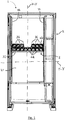
Figure 1 shows a spiral vending machine of the present invention, -
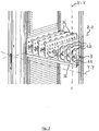
Figure 2 shows a tray of the vending machine ofFigure 1 , -
Figure 3 shows a compartment of the tray ofFigure 2 , -
Figure 4 shows a side view of the compartment ofFigure 3 . - Referring to the accompanying figures,
numeral 1 generally designates a vending machine. Thevending machine 1 comprises aframe 2 having arear wall 21,side walls 22 and a front wall which delimit a storage chamber for products to be dispensed. - The
vending machine 1 comprises a plurality oftrays 3 and a pick-up zone (for simplicity only onetray 3 is depicted in the figures). Thetrays 3 are arranged one above the other in the storage chamber, are spaced from each other in a first direction X-X, which is preferably vertical, and are connected to theside walls 22 of theframe 2. - Each
tray 3 comprises a preferablyflat base panel 31, upon which the products to be dispensed can be laid. The trays extend between afront edge 32, spaced from the front wall, and arear edge 33 situated proximate to therear wall 21. - A front space is defined between the
front edges 32 and the front wall to make the products available to a user. In a possible embodiment, the products to be picked up fall into the front space and reach a pick-up zone, placed below the storage chamber. According to a different embodiment, thevending machine 1 comprises an arm which extends into the front space, and carries the products to be picked up from thetrays 3 to the pick-up zone through the front space. - Each
tray 3 comprises a plurality ofpartitions 34. Thepartitions 34 are fixed to thebase panel 31 of theirrespective tray 3, and are spaced in a second direction Y-Y perpendicular to the first direction X-X, and define a plurality of compartments of theirrespective tray 3 in the storage chamber. - Namely, each compartment is delimited at its sides by two
adjacent partitions 34 and vertically (i.e. in the direction X-X) by thebase panels 31 of theirrespective tray 3 and of thetray 3 that is directly above it (or by a top surface of the frame 2). Each compartment extends between thefront edge 32 and therear edge 33 of itsrespective tray 3. - Each
tray 3 comprises a plurality ofspiral coils 4a, 4b, eachspiral coil 4a, 4b being disposed within a respective compartment. Eachspiral coil 4a, 4b has a helical shape and extends about its respective axis A-A, B-B with a number of turns, a radius and a helical pitch. The axis A-A, B-B of eachspiral 4a, 4b extends in a third direction Z-Z perpendicular to the first direction X-X and the second direction Y-Y. - Each
spiral coil 4a, 4b extends along the entire length of its respective compartment, between a rear end 41a, 41b and anopposite front end 42a, 42b, which are spaced from each other in the third direction Z-Z. Eachtray 3 comprisessupport members 35 situated at therear edge 33 of thetray 3. The rear end 41 a, 41b of eachspiral coil 4a, 4b is rotatably connected to thesupport members 35 of itsrespective tray 3, whereas thefront end 42a, 42b is free. - The
vending machine 1 comprises motor means (not shown), which are configured to rotate one or morespiral coils 4a, 4b about their respective axes A-A, B-B through thesupport members 35. The products to be dispensed are disposed between two consecutive turns of aspiral coil 4a, 4b and the rotation of thespiral coil 4a, 4b impels the products in the third direction Z-Z toward thefront edge 32 of atray 3. - In one aspect of the invention, at least one compartment comprises a first spiral coil 4a and a second
spiral coil 4b, the axis A-A of the first spiral coil 4a and the axis B-B of the secondspiral coil 4b being spaced from each other in the first direction X-X. - Advantageously, a long product may be disposed in a compartment of the vending machine with a vertical orientation, i.e. along the first direction X-X, and is adequately supported by the spiral coils only, with the compartment not being required to have additional support elements for the products, and to have an excessive width in the second direction Y-Y.
- In one aspect of the invention, the first spiral coil 4a comprises engagement members 43a at its front end 42a, which are configured to engage the
front end 42b of the secondspiral coil 4b along a section of the angular rotation path of the first spiral coil 4a and the secondspiral coil 4b. - It shall be noted that, according to various embodiments, the engagement members 43a may be provided in the underlying spiral coil or in the overlying spiral coil only.
- In a preferred embodiment, the second
spiral coil 4b also comprisesengagement members 43b at itsfront end 42b. Theengagement members 43b of the secondspiral coil 4b are configured to engage the engagement members 43a of the first spiral coil 4a along said section of the angular rotation path or, equivalently, the engagement members 43 a of the first spiral coil 4a are configured to engage thefront end 42b of the secondspiral coil 4b at theengagement members 43b of the second spiral 4b, in detail by realizing a contact therewith. - Particularly, the
engagement members 43a, 43b of the first and/or secondspiral coils 4a, 4b provide contact, i.e. abutment, between the first spiral coil 4a and the secondspiral coil 4b, such that thefront end 42a, 42b of one of thespiral coils 4a 4b, namely the overlying spiral coil, will be supported by thefront end 42a, 42b of the other, underlying, spiral coil, through theengagement members 43a, 43b of the first and/or secondspiral coils 4a, 4b and/or through contact therebetween. - In one embodiment, the
engagement members 43a, 43b of a spiral coil 4a, 4a have the shape of a wing. The wing has a base 44a, 44b fixed to thefront end 42a, 42b of its respectivespiral coil 4a, 4b. The wing extends from the front end 42a of its respectivespiral coil 4a, 4b in the third direction Z-Z toward the front wall. - In one embodiment, the first spiral coil 4a is placed below the second
spiral coil 4b and rests upon thebase panel 31 of itsrespective tray 3. The second spiral coil 4a is placed vertically above the first spiral coil 4a, and the wing of the secondspiral coil 4b rests upon the wing of the first spiral coil 4a along said section of their angular rotation path. - Advantageously, the overlying spiral coil, e.g. the
second coil 4b, is supported both at the rear end 41b, by thesupport members 35 of thetray 3, and at thefront end 42b, by theengagement members 43a, 43b of the first spiral coil 4a and/or the secondspiral coil 4b, and by the first spiral coil 4a. This prevents that the secondspiral coil 4b tilts toward the first spiral 4a under its own weight, and therefore prevents that thefront end 42b of the secondspiral coil 4b approaches the front end 42a of the first spiral coil 4a, thereby hindering the rotary motion of the first spiral coil 4a. - Advantageously the engagement members 43a, 43 provide support to the
front end 42b of the secondspiral coil 4b during rotation of thespiral coils 4a, 4b. - Preferably, in order to ensure smooth movement of the products to be dispensed, the distance between the axis A-A of the first spiral coil 4a and the axis B-B of the second
spiral coil 4b is constant, and is equal to, or greater than, the sum of the radii of the first spiral coil 4a and the secondspiral coil 4b. Preferably, the first spiral coil 4a and the secondspiral coil 4b have the same geometric characteristics, i.e. the same radius, pitch and number of turns, and even more preferably, but without limitation, they are configured to rotate in two respective opposite directions of rotation. - It will be appreciated from the above that the vending machine of the present invention obviates the above mentioned prior art drawbacks.
- Those skilled in the art will obviously appreciate that a number of changes and variants may be made to the invention as described hereinbefore to meet specific needs, without departure from the scope of the invention as defined in the following claims. For example, a compartment may be provided in which more than two spiral coils are placed vertically one above the other, or the spiral coils may be offset in the third direction Z-Z.
Claims (7)
- A vending machine (1) comprising:- a frame (2) having a rear wall (21), side walls (22) and a front wall which delimit a storage chamber (3) for products to be dispensed, and- a plurality of trays (3) arranged in the storage chamber one above the other and spaced apart in a first direction (X-X),wherein each tray (3) extends from a front edge (32), spaced from the front wall, and a rear edge (33) situated proximate to the rear wall (21), and comprises:- a base panel (31);- a plurality of partitions (34) arranged on the base panel (31) side-by-side and spaced apart in a second direction (Y-Y) perpendicular to the first direction (X-X), to define a plurality of compartments on said tray (3),- support members (35) situated at the rear edge (33) of the tray (3), and- a plurality of spiral coils (4a, 4b),wherein- each spiral coil (4a, 4b) extends along an axis (A-A, B-B) extending in a third direction (Z-Z), perpendicular to the first direction (X-X) and the second direction (Y-Y),- each spiral coil (4a, 4b) extends between a rear end (41a, 41b), which is rotatably connected to the support members (35), and an opposite free front end (42a, 42b),- at least one compartment comprises a first spiral coil (4a) and a second spiral coil (4b),characterized in that:- the axis (A-A) of the first spiral coil (4a) and the axis (B-B) of the second spiral coil (4b) are spaced apart in the first direction (X-X),- the first spiral coil (4a) comprises engagement members (43 a) at its front end (42a), which are configured to engage the front end (42b) of the second spiral coil (4b) along a section of the angular rotation path of the first spiral coil (4a) and the second spiral coil (4b).
- A vending machine (1) as claimed in claim 1, wherein the engagement members (43a) of the first spiral coil (4a) are configured to engage the front end (42b) of the second spiral coil (4b) by providing contact between the engagement members (43a) of the first spiral coil (4a) and the front end (42b) of the second spiral coil (4b) such that the front end (42a, 42b) of one of the spiral coils (4a, 4b) is supported by the front end (42a, 42b) of the other spiral coil (4a, 4b) through the engagement members (43a) of the first spiral coil (4a).
- A vending machine (1) as claimed in claim 1, wherein the second spiral coil (4b) comprises engagement members (43b) at its front end (42b), the engagement members (43a) of the first spiral coil (4a) being configured to engage the front end (42b) of the second spiral coil (4b) at the engagement members (43b) of the second spiral coil (4b) along said section of angular rotation path.
- A vending machine (1) as claimed in claim 3, wherein the engagement members (43a) of the first spiral coil (4a) are configured to engage the engagement members (43b) of the second spiral coil (4b) by providing contact between the engagement members (43a) of the first spiral coil (4a) and the engagement members (43b) of the second spiral coil (4b), such that the front end (42b) of the second spiral coil (4b) is supported by the front end (42a) of the first spiral coil (4a) through the contact of the engagement members (43a, 43b) of the first and second spiral coils (4a).
- A vending machine (1) as claimed in any of claims 1 to 4, wherein:- each engagement member (43a, 43b) is a wing,- each wing has a base (44a, 44b) fixed on the front end (42a, 42b) of its respective spiral coil (4a, 4b),- said wing extends from the front end (42a, 42b) of its respective spiral coil (4a, 4b) in the third direction (Z-Z) toward the front wall of the frame.
- A vending machine (1) as claimed in claims 3 and 5, wherein:- the first spiral coil (4a) rests upon the base panel (31) of its respective tray (31),- the second spiral coil (4b) is placed above the first spiral coil (4a), and- the wing of the second spiral coil (4b) rests upon the wing of the first spiral coil (4a) along said section of angular rotation path.
- A vending machine (1) as claimed in any of claims 1 to 6, wherein the distance between the axis (A-A) of the first spiral coil (4a) and the axis (B-B) of the second spiral coil (4b) is constant and is equal to, or greater than, the sum of the radii of the first spiral coil (4a) and the second spiral coil (4b).
Applications Claiming Priority (1)
| Application Number | Priority Date | Filing Date | Title |
|---|---|---|---|
| ITUA2016A001651A ITUA20161651A1 (en) | 2016-03-14 | 2016-03-14 | Vending machine. |
Publications (2)
| Publication Number | Publication Date |
|---|---|
| EP3220365A1 true EP3220365A1 (en) | 2017-09-20 |
| EP3220365B1 EP3220365B1 (en) | 2019-11-20 |
Family
ID=56203704
Family Applications (1)
| Application Number | Title | Priority Date | Filing Date |
|---|---|---|---|
| EP17160021.6A Active EP3220365B1 (en) | 2016-03-14 | 2017-03-09 | Vending machine |
Country Status (3)
| Country | Link |
|---|---|
| EP (1) | EP3220365B1 (en) |
| ES (1) | ES2769266T3 (en) |
| IT (1) | ITUA20161651A1 (en) |
Cited By (1)
| Publication number | Priority date | Publication date | Assignee | Title |
|---|---|---|---|---|
| US20210137788A1 (en) * | 2019-11-12 | 2021-05-13 | Omnicell, Inc. | Dispensing systems and methods for prefilled syringes |
Citations (5)
| Publication number | Priority date | Publication date | Assignee | Title |
|---|---|---|---|---|
| US3036730A (en) * | 1958-08-29 | 1962-05-29 | Westinghouse Electric Corp | Dispensing apparatus |
| WO2001027739A1 (en) * | 1999-10-12 | 2001-04-19 | Paulucci Jeno F | Vending machine |
| EP1881464A1 (en) * | 2006-07-21 | 2008-01-23 | DAMIAN S.r.l. | Helical coil dispenser for vending machines and vending machine comprising such dispenser |
| EP2323112A1 (en) * | 2009-10-23 | 2011-05-18 | F.A.S. International S.p.A. | Vending machine |
| US8038018B1 (en) * | 2008-03-25 | 2011-10-18 | Vendmore Systems, Llc | Vending machine product stabilizer |
-
2016
- 2016-03-14 IT ITUA2016A001651A patent/ITUA20161651A1/en unknown
-
2017
- 2017-03-09 EP EP17160021.6A patent/EP3220365B1/en active Active
- 2017-03-09 ES ES17160021T patent/ES2769266T3/en active Active
Patent Citations (5)
| Publication number | Priority date | Publication date | Assignee | Title |
|---|---|---|---|---|
| US3036730A (en) * | 1958-08-29 | 1962-05-29 | Westinghouse Electric Corp | Dispensing apparatus |
| WO2001027739A1 (en) * | 1999-10-12 | 2001-04-19 | Paulucci Jeno F | Vending machine |
| EP1881464A1 (en) * | 2006-07-21 | 2008-01-23 | DAMIAN S.r.l. | Helical coil dispenser for vending machines and vending machine comprising such dispenser |
| US8038018B1 (en) * | 2008-03-25 | 2011-10-18 | Vendmore Systems, Llc | Vending machine product stabilizer |
| EP2323112A1 (en) * | 2009-10-23 | 2011-05-18 | F.A.S. International S.p.A. | Vending machine |
Cited By (4)
| Publication number | Priority date | Publication date | Assignee | Title |
|---|---|---|---|---|
| US20210137788A1 (en) * | 2019-11-12 | 2021-05-13 | Omnicell, Inc. | Dispensing systems and methods for prefilled syringes |
| US11426329B2 (en) * | 2019-11-12 | 2022-08-30 | Omnicell, Inc. | Dispensing systems and methods for prefilled syringes |
| US20220347053A1 (en) * | 2019-11-12 | 2022-11-03 | Omnicell, Inc. | Dispensing systems and methods for prefilled syringes |
| US12514785B2 (en) * | 2019-11-12 | 2026-01-06 | Omnicell, Inc. | Dispensing systems and methods for prefilled syringes |
Also Published As
| Publication number | Publication date |
|---|---|
| ES2769266T3 (en) | 2020-06-25 |
| ITUA20161651A1 (en) | 2017-09-14 |
| EP3220365B1 (en) | 2019-11-20 |
Similar Documents
| Publication | Publication Date | Title |
|---|---|---|
| US2176384A (en) | Self-service store construction | |
| US7066348B2 (en) | Vending machine with horizontal product presentation | |
| EP0211816A2 (en) | Tray stand | |
| EP2441354B1 (en) | Shelf unit and shelving system | |
| US4149653A (en) | Insert member for a helical dispensing coil | |
| CN107105906B (en) | End cover for roller shelf of showcase | |
| US3194620A (en) | Storage and dispensing unit | |
| US4899906A (en) | Automatic dispenser, particularly for packages of food products | |
| AU763550B2 (en) | Distributor | |
| US4148412A (en) | Shelf configuration for spiral vendor | |
| EP3220365B1 (en) | Vending machine | |
| US4944414A (en) | Shelf assembly for vending tubular products | |
| CN108140277A (en) | Dispensing device for container | |
| EP2405785B1 (en) | An improved storage carousel | |
| US4930663A (en) | Article alignment unit | |
| JP4042930B2 (en) | Product display unit | |
| EP2718912B1 (en) | Improved vending machine | |
| US1882238A (en) | Delivery and loading means for bakery products or the like | |
| EP1797800A2 (en) | Capsule dispensing apparatus for vending machines, in particular beverage vending machines | |
| US2680051A (en) | Vending machine with dual magazines arranged for alternate delivery | |
| CS199558B2 (en) | Unloading stand | |
| CN220141244U (en) | Product display rack | |
| CN215932731U (en) | A circulating and rotating type delivery device and a vending device having the same | |
| RU2732197C1 (en) | Vending machine | |
| US2903155A (en) | Bottle dispensing apparatus |
Legal Events
| Date | Code | Title | Description |
|---|---|---|---|
| PUAI | Public reference made under article 153(3) epc to a published international application that has entered the european phase |
Free format text: ORIGINAL CODE: 0009012 |
|
| STAA | Information on the status of an ep patent application or granted ep patent |
Free format text: STATUS: THE APPLICATION HAS BEEN PUBLISHED |
|
| AK | Designated contracting states |
Kind code of ref document: A1 Designated state(s): AL AT BE BG CH CY CZ DE DK EE ES FI FR GB GR HR HU IE IS IT LI LT LU LV MC MK MT NL NO PL PT RO RS SE SI SK SM TR |
|
| AX | Request for extension of the european patent |
Extension state: BA ME |
|
| STAA | Information on the status of an ep patent application or granted ep patent |
Free format text: STATUS: REQUEST FOR EXAMINATION WAS MADE |
|
| 17P | Request for examination filed |
Effective date: 20180316 |
|
| RBV | Designated contracting states (corrected) |
Designated state(s): AL AT BE BG CH CY CZ DE DK EE ES FI FR GB GR HR HU IE IS IT LI LT LU LV MC MK MT NL NO PL PT RO RS SE SI SK SM TR |
|
| RIC1 | Information provided on ipc code assigned before grant |
Ipc: G07F 11/36 20060101AFI20190508BHEP |
|
| GRAP | Despatch of communication of intention to grant a patent |
Free format text: ORIGINAL CODE: EPIDOSNIGR1 |
|
| STAA | Information on the status of an ep patent application or granted ep patent |
Free format text: STATUS: GRANT OF PATENT IS INTENDED |
|
| INTG | Intention to grant announced |
Effective date: 20190705 |
|
| GRAS | Grant fee paid |
Free format text: ORIGINAL CODE: EPIDOSNIGR3 |
|
| GRAA | (expected) grant |
Free format text: ORIGINAL CODE: 0009210 |
|
| STAA | Information on the status of an ep patent application or granted ep patent |
Free format text: STATUS: THE PATENT HAS BEEN GRANTED |
|
| AK | Designated contracting states |
Kind code of ref document: B1 Designated state(s): AL AT BE BG CH CY CZ DE DK EE ES FI FR GB GR HR HU IE IS IT LI LT LU LV MC MK MT NL NO PL PT RO RS SE SI SK SM TR |
|
| REG | Reference to a national code |
Ref country code: GB Ref legal event code: FG4D |
|
| REG | Reference to a national code |
Ref country code: CH Ref legal event code: EP |
|
| REG | Reference to a national code |
Ref country code: IE Ref legal event code: FG4D |
|
| REG | Reference to a national code |
Ref country code: DE Ref legal event code: R096 Ref document number: 602017008786 Country of ref document: DE |
|
| REG | Reference to a national code |
Ref country code: AT Ref legal event code: REF Ref document number: 1205050 Country of ref document: AT Kind code of ref document: T Effective date: 20191215 |
|
| RAP2 | Party data changed (patent owner data changed or rights of a patent transferred) |
Owner name: FAS INTERNATIONAL S.R.L. |
|
| REG | Reference to a national code |
Ref country code: NL Ref legal event code: MP Effective date: 20191120 |
|
| REG | Reference to a national code |
Ref country code: LT Ref legal event code: MG4D |
|
| PG25 | Lapsed in a contracting state [announced via postgrant information from national office to epo] |
Ref country code: LV Free format text: LAPSE BECAUSE OF FAILURE TO SUBMIT A TRANSLATION OF THE DESCRIPTION OR TO PAY THE FEE WITHIN THE PRESCRIBED TIME-LIMIT Effective date: 20191120 Ref country code: SE Free format text: LAPSE BECAUSE OF FAILURE TO SUBMIT A TRANSLATION OF THE DESCRIPTION OR TO PAY THE FEE WITHIN THE PRESCRIBED TIME-LIMIT Effective date: 20191120 Ref country code: LT Free format text: LAPSE BECAUSE OF FAILURE TO SUBMIT A TRANSLATION OF THE DESCRIPTION OR TO PAY THE FEE WITHIN THE PRESCRIBED TIME-LIMIT Effective date: 20191120 Ref country code: GR Free format text: LAPSE BECAUSE OF FAILURE TO SUBMIT A TRANSLATION OF THE DESCRIPTION OR TO PAY THE FEE WITHIN THE PRESCRIBED TIME-LIMIT Effective date: 20200221 Ref country code: NL Free format text: LAPSE BECAUSE OF FAILURE TO SUBMIT A TRANSLATION OF THE DESCRIPTION OR TO PAY THE FEE WITHIN THE PRESCRIBED TIME-LIMIT Effective date: 20191120 Ref country code: NO Free format text: LAPSE BECAUSE OF FAILURE TO SUBMIT A TRANSLATION OF THE DESCRIPTION OR TO PAY THE FEE WITHIN THE PRESCRIBED TIME-LIMIT Effective date: 20200220 Ref country code: FI Free format text: LAPSE BECAUSE OF FAILURE TO SUBMIT A TRANSLATION OF THE DESCRIPTION OR TO PAY THE FEE WITHIN THE PRESCRIBED TIME-LIMIT Effective date: 20191120 Ref country code: BG Free format text: LAPSE BECAUSE OF FAILURE TO SUBMIT A TRANSLATION OF THE DESCRIPTION OR TO PAY THE FEE WITHIN THE PRESCRIBED TIME-LIMIT Effective date: 20200220 |
|
| PG25 | Lapsed in a contracting state [announced via postgrant information from national office to epo] |
Ref country code: RS Free format text: LAPSE BECAUSE OF FAILURE TO SUBMIT A TRANSLATION OF THE DESCRIPTION OR TO PAY THE FEE WITHIN THE PRESCRIBED TIME-LIMIT Effective date: 20191120 Ref country code: HR Free format text: LAPSE BECAUSE OF FAILURE TO SUBMIT A TRANSLATION OF THE DESCRIPTION OR TO PAY THE FEE WITHIN THE PRESCRIBED TIME-LIMIT Effective date: 20191120 Ref country code: IS Free format text: LAPSE BECAUSE OF FAILURE TO SUBMIT A TRANSLATION OF THE DESCRIPTION OR TO PAY THE FEE WITHIN THE PRESCRIBED TIME-LIMIT Effective date: 20200320 |
|
| REG | Reference to a national code |
Ref country code: ES Ref legal event code: FG2A Ref document number: 2769266 Country of ref document: ES Kind code of ref document: T3 Effective date: 20200625 |
|
| PG25 | Lapsed in a contracting state [announced via postgrant information from national office to epo] |
Ref country code: AL Free format text: LAPSE BECAUSE OF FAILURE TO SUBMIT A TRANSLATION OF THE DESCRIPTION OR TO PAY THE FEE WITHIN THE PRESCRIBED TIME-LIMIT Effective date: 20191120 |
|
| PG25 | Lapsed in a contracting state [announced via postgrant information from national office to epo] |
Ref country code: RO Free format text: LAPSE BECAUSE OF FAILURE TO SUBMIT A TRANSLATION OF THE DESCRIPTION OR TO PAY THE FEE WITHIN THE PRESCRIBED TIME-LIMIT Effective date: 20191120 Ref country code: CZ Free format text: LAPSE BECAUSE OF FAILURE TO SUBMIT A TRANSLATION OF THE DESCRIPTION OR TO PAY THE FEE WITHIN THE PRESCRIBED TIME-LIMIT Effective date: 20191120 Ref country code: DK Free format text: LAPSE BECAUSE OF FAILURE TO SUBMIT A TRANSLATION OF THE DESCRIPTION OR TO PAY THE FEE WITHIN THE PRESCRIBED TIME-LIMIT Effective date: 20191120 Ref country code: PT Free format text: LAPSE BECAUSE OF FAILURE TO SUBMIT A TRANSLATION OF THE DESCRIPTION OR TO PAY THE FEE WITHIN THE PRESCRIBED TIME-LIMIT Effective date: 20200412 Ref country code: EE Free format text: LAPSE BECAUSE OF FAILURE TO SUBMIT A TRANSLATION OF THE DESCRIPTION OR TO PAY THE FEE WITHIN THE PRESCRIBED TIME-LIMIT Effective date: 20191120 |
|
| REG | Reference to a national code |
Ref country code: AT Ref legal event code: MK05 Ref document number: 1205050 Country of ref document: AT Kind code of ref document: T Effective date: 20191120 |
|
| REG | Reference to a national code |
Ref country code: DE Ref legal event code: R097 Ref document number: 602017008786 Country of ref document: DE |
|
| PG25 | Lapsed in a contracting state [announced via postgrant information from national office to epo] |
Ref country code: SK Free format text: LAPSE BECAUSE OF FAILURE TO SUBMIT A TRANSLATION OF THE DESCRIPTION OR TO PAY THE FEE WITHIN THE PRESCRIBED TIME-LIMIT Effective date: 20191120 Ref country code: SM Free format text: LAPSE BECAUSE OF FAILURE TO SUBMIT A TRANSLATION OF THE DESCRIPTION OR TO PAY THE FEE WITHIN THE PRESCRIBED TIME-LIMIT Effective date: 20191120 |
|
| PLBE | No opposition filed within time limit |
Free format text: ORIGINAL CODE: 0009261 |
|
| STAA | Information on the status of an ep patent application or granted ep patent |
Free format text: STATUS: NO OPPOSITION FILED WITHIN TIME LIMIT |
|
| REG | Reference to a national code |
Ref country code: GB Ref legal event code: 732E Free format text: REGISTERED BETWEEN 20200903 AND 20200910 |
|
| REG | Reference to a national code |
Ref country code: DE Ref legal event code: R119 Ref document number: 602017008786 Country of ref document: DE |
|
| 26N | No opposition filed |
Effective date: 20200821 |
|
| PG25 | Lapsed in a contracting state [announced via postgrant information from national office to epo] |
Ref country code: MC Free format text: LAPSE BECAUSE OF FAILURE TO SUBMIT A TRANSLATION OF THE DESCRIPTION OR TO PAY THE FEE WITHIN THE PRESCRIBED TIME-LIMIT Effective date: 20191120 |
|
| REG | Reference to a national code |
Ref country code: CH Ref legal event code: PL |
|
| PG25 | Lapsed in a contracting state [announced via postgrant information from national office to epo] |
Ref country code: SI Free format text: LAPSE BECAUSE OF FAILURE TO SUBMIT A TRANSLATION OF THE DESCRIPTION OR TO PAY THE FEE WITHIN THE PRESCRIBED TIME-LIMIT Effective date: 20191120 Ref country code: PL Free format text: LAPSE BECAUSE OF FAILURE TO SUBMIT A TRANSLATION OF THE DESCRIPTION OR TO PAY THE FEE WITHIN THE PRESCRIBED TIME-LIMIT Effective date: 20191120 Ref country code: AT Free format text: LAPSE BECAUSE OF FAILURE TO SUBMIT A TRANSLATION OF THE DESCRIPTION OR TO PAY THE FEE WITHIN THE PRESCRIBED TIME-LIMIT Effective date: 20191120 |
|
| REG | Reference to a national code |
Ref country code: BE Ref legal event code: MM Effective date: 20200331 |
|
| PG25 | Lapsed in a contracting state [announced via postgrant information from national office to epo] |
Ref country code: LU Free format text: LAPSE BECAUSE OF NON-PAYMENT OF DUE FEES Effective date: 20200309 |
|
| PG25 | Lapsed in a contracting state [announced via postgrant information from national office to epo] |
Ref country code: LI Free format text: LAPSE BECAUSE OF NON-PAYMENT OF DUE FEES Effective date: 20200331 Ref country code: DE Free format text: LAPSE BECAUSE OF NON-PAYMENT OF DUE FEES Effective date: 20201001 Ref country code: IE Free format text: LAPSE BECAUSE OF NON-PAYMENT OF DUE FEES Effective date: 20200309 Ref country code: CH Free format text: LAPSE BECAUSE OF NON-PAYMENT OF DUE FEES Effective date: 20200331 Ref country code: FR Free format text: LAPSE BECAUSE OF NON-PAYMENT OF DUE FEES Effective date: 20200331 |
|
| PG25 | Lapsed in a contracting state [announced via postgrant information from national office to epo] |
Ref country code: BE Free format text: LAPSE BECAUSE OF NON-PAYMENT OF DUE FEES Effective date: 20200331 |
|
| REG | Reference to a national code |
Ref country code: ES Ref legal event code: FD2A Effective date: 20210727 |
|
| PG25 | Lapsed in a contracting state [announced via postgrant information from national office to epo] |
Ref country code: ES Free format text: LAPSE BECAUSE OF NON-PAYMENT OF DUE FEES Effective date: 20200310 |
|
| PG25 | Lapsed in a contracting state [announced via postgrant information from national office to epo] |
Ref country code: TR Free format text: LAPSE BECAUSE OF FAILURE TO SUBMIT A TRANSLATION OF THE DESCRIPTION OR TO PAY THE FEE WITHIN THE PRESCRIBED TIME-LIMIT Effective date: 20191120 Ref country code: MT Free format text: LAPSE BECAUSE OF FAILURE TO SUBMIT A TRANSLATION OF THE DESCRIPTION OR TO PAY THE FEE WITHIN THE PRESCRIBED TIME-LIMIT Effective date: 20191120 Ref country code: CY Free format text: LAPSE BECAUSE OF FAILURE TO SUBMIT A TRANSLATION OF THE DESCRIPTION OR TO PAY THE FEE WITHIN THE PRESCRIBED TIME-LIMIT Effective date: 20191120 |
|
| PG25 | Lapsed in a contracting state [announced via postgrant information from national office to epo] |
Ref country code: MK Free format text: LAPSE BECAUSE OF FAILURE TO SUBMIT A TRANSLATION OF THE DESCRIPTION OR TO PAY THE FEE WITHIN THE PRESCRIBED TIME-LIMIT Effective date: 20191120 |
|
| P01 | Opt-out of the competence of the unified patent court (upc) registered |
Effective date: 20230602 |
|
| P02 | Opt-out of the competence of the unified patent court (upc) changed |
Effective date: 20230818 |
|
| PG25 | Lapsed in a contracting state [announced via postgrant information from national office to epo] |
Ref country code: IS Free format text: LAPSE BECAUSE OF NON-PAYMENT OF DUE FEES Effective date: 20200320 |
|
| PGFP | Annual fee paid to national office [announced via postgrant information from national office to epo] |
Ref country code: GB Payment date: 20260324 Year of fee payment: 10 |
|
| PGFP | Annual fee paid to national office [announced via postgrant information from national office to epo] |
Ref country code: IT Payment date: 20260327 Year of fee payment: 10 |