EP3220271A1 - Data collection device, data collection system, control method, and program - Google Patents
Data collection device, data collection system, control method, and program Download PDFInfo
- Publication number
- EP3220271A1 EP3220271A1 EP15869748.2A EP15869748A EP3220271A1 EP 3220271 A1 EP3220271 A1 EP 3220271A1 EP 15869748 A EP15869748 A EP 15869748A EP 3220271 A1 EP3220271 A1 EP 3220271A1
- Authority
- EP
- European Patent Office
- Prior art keywords
- data
- output
- collection device
- internal log
- data collection
- Prior art date
- Legal status (The legal status is an assumption and is not a legal conclusion. Google has not performed a legal analysis and makes no representation as to the accuracy of the status listed.)
- Granted
Links
Images


Classifications
-
- F—MECHANICAL ENGINEERING; LIGHTING; HEATING; WEAPONS; BLASTING
- F24—HEATING; RANGES; VENTILATING
- F24F—AIR-CONDITIONING; AIR-HUMIDIFICATION; VENTILATION; USE OF AIR CURRENTS FOR SCREENING
- F24F11/00—Control or safety arrangements
- F24F11/89—Arrangement or mounting of control or safety devices
-
- G—PHYSICS
- G06—COMPUTING OR CALCULATING; COUNTING
- G06F—ELECTRIC DIGITAL DATA PROCESSING
- G06F11/00—Error detection; Error correction; Monitoring
- G06F11/07—Responding to the occurrence of a fault, e.g. fault tolerance
- G06F11/0703—Error or fault processing not based on redundancy, i.e. by taking additional measures to deal with the error or fault not making use of redundancy in operation, in hardware, or in data representation
- G06F11/0706—Error or fault processing not based on redundancy, i.e. by taking additional measures to deal with the error or fault not making use of redundancy in operation, in hardware, or in data representation the processing taking place on a specific hardware platform or in a specific software environment
- G06F11/0736—Error or fault processing not based on redundancy, i.e. by taking additional measures to deal with the error or fault not making use of redundancy in operation, in hardware, or in data representation the processing taking place on a specific hardware platform or in a specific software environment in functional embedded systems, i.e. in a data processing system designed as a combination of hardware and software dedicated to performing a certain function
-
- F—MECHANICAL ENGINEERING; LIGHTING; HEATING; WEAPONS; BLASTING
- F24—HEATING; RANGES; VENTILATING
- F24F—AIR-CONDITIONING; AIR-HUMIDIFICATION; VENTILATION; USE OF AIR CURRENTS FOR SCREENING
- F24F11/00—Control or safety arrangements
- F24F11/30—Control or safety arrangements for purposes related to the operation of the system, e.g. for safety or monitoring
-
- G—PHYSICS
- G06—COMPUTING OR CALCULATING; COUNTING
- G06F—ELECTRIC DIGITAL DATA PROCESSING
- G06F11/00—Error detection; Error correction; Monitoring
- G06F11/07—Responding to the occurrence of a fault, e.g. fault tolerance
- G06F11/0703—Error or fault processing not based on redundancy, i.e. by taking additional measures to deal with the error or fault not making use of redundancy in operation, in hardware, or in data representation
- G06F11/079—Root cause analysis, i.e. error or fault diagnosis
-
- G—PHYSICS
- G06—COMPUTING OR CALCULATING; COUNTING
- G06F—ELECTRIC DIGITAL DATA PROCESSING
- G06F11/00—Error detection; Error correction; Monitoring
- G06F11/07—Responding to the occurrence of a fault, e.g. fault tolerance
- G06F11/0796—Safety measures, i.e. ensuring safe condition in the event of error, e.g. for controlling element
-
- G—PHYSICS
- G06—COMPUTING OR CALCULATING; COUNTING
- G06F—ELECTRIC DIGITAL DATA PROCESSING
- G06F11/00—Error detection; Error correction; Monitoring
- G06F11/30—Monitoring
- G06F11/3058—Monitoring arrangements for monitoring environmental properties or parameters of the computing system or of the computing system component, e.g. monitoring of power, currents, temperature, humidity, position, vibrations
-
- G—PHYSICS
- G06—COMPUTING OR CALCULATING; COUNTING
- G06F—ELECTRIC DIGITAL DATA PROCESSING
- G06F11/00—Error detection; Error correction; Monitoring
- G06F11/30—Monitoring
- G06F11/34—Recording or statistical evaluation of computer activity, e.g. of down time, of input/output operation ; Recording or statistical evaluation of user activity, e.g. usability assessment
-
- G—PHYSICS
- G06—COMPUTING OR CALCULATING; COUNTING
- G06F—ELECTRIC DIGITAL DATA PROCESSING
- G06F11/00—Error detection; Error correction; Monitoring
- G06F11/30—Monitoring
- G06F11/34—Recording or statistical evaluation of computer activity, e.g. of down time, of input/output operation ; Recording or statistical evaluation of user activity, e.g. usability assessment
- G06F11/3409—Recording or statistical evaluation of computer activity, e.g. of down time, of input/output operation ; Recording or statistical evaluation of user activity, e.g. usability assessment for performance assessment
Definitions
- the present invention relates to a data collection device of an air conditioner, a data collection system, a control method, and a program.
- the logging of internal log data of an air conditioner and the utilization of the data for service have been generally performed.
- a maintenance worker connects a data logger for an air conditioner to the air conditioner, and makes the internal log data of the air conditioner written in a storage unit included in the data logger.
- the maintenance worker connects a PC to the data logger, transmits the internal log data accumulated in the storage unit of the data logger to the PC, and analyzes the internal log data to thereby utilize the presence or absence and cause of an abnormality for an examination.
- PTL1 as the related art discloses a general-purpose data logger that instructs a PC connected to the device to execute a specific program, which is suitable for a preset specific condition, when receiving a signal satisfying the condition.
- the data logger for an air conditioner of the related art cannot report the detection of an abnormality in real time even when the internal log data acquired from the air conditioner includes an abnormal value.
- the data logger disclosed in PTL 1 can report an abnormal value in real time, it is premised that the data logger is connected to a PC at all times. Accordingly, it is difficult to use the data logger as a data logger for an air conditioner.
- the present invention provides a data collection device, a data collection system, a control method, and a program which are capable of solving the above-described problem.
- a data collection device including a data reception unit that is connected to an air conditioner and acquires internal log data in a binary format from a controller of the air conditioner, an output determination unit that compares a condition value which is set in a binary format in advance with the acquired internal log data to thereby determine whether or not an output condition is satisfied, and an external output unit that outputs a notification signal in a case where the output determination unit determines that the output condition is satisfied.
- the output determination unit may extract data corresponding to a parameter to be monitored from the internal log data acquired by the data reception unit, on the basis of a correspondence relationship between a data position in the internal log data which is determined in advance and a kind of parameter allocated to data at the position, and may compare the extracted data with the condition value.
- a data collection system including the data collection device according to claim 1 or 2, and a data analysis device that is detachably connected to the data collection device, in which the data collection device further includes a storage unit that stores the internal log data acquired by the data reception unit, and in which the data analysis device includes a log data acquisition unit that acquires the internal log data written in the storage unit of the data collection device, and a conversion unit that converts the internal log data acquired by the log data acquisition unit into text data.
- the data analysis device may further include a setting reception unit that receives an input of the output condition, and a data conversion unit that converts a condition value included in the output condition into a binary format, and outputs the output condition to the data collection device, and the data collection device may further include an output condition setting unit that acquires the output condition which is output by the data conversion unit and writes the acquired output condition in the storage unit.
- a control method including causing a data collection device connected to an air conditioner to acquire internal log data in a binary format from a controller of the air conditioner, to compare a condition value which is set in a binary format in advance with the acquired internal log data to thereby determine whether or not an output condition is satisfied, and to output a notification signal in a case where it is determined that the output condition is satisfied.
- a program causing a computer of a data collection device to function as means, which is connected to an air conditioner, for acquiring internal log data in a binary format from a controller of the air conditioner, means for comparing a condition value which is set in a binary format in advance with the acquired internal log data to thereby determine whether or not an output condition is satisfied, and means for outputting a notification signal in a case where the output condition is satisfied.
- FIGS. 1 to 8 a data collection device according to an embodiment of the present invention will be described with reference to FIGS. 1 to 8 .
- FIG. 1 is a schematic diagram illustrating an example of a data collection device connected to an air conditioner according to an embodiment of the present invention.
- an air conditioner (outdoor unit) 10 is provided with a controller 12.
- the controller 12 collects internal log data of the air conditioner 10 and controls the air conditioner.
- the internal log data refers to data indicating the internal state of the air conditioner 10 which is necessary for the control and monitoring of the air conditioner 10.
- the internal log data refers to detection information such as outside air temperature, the pressure of a refrigerant gas, the temperature of a compressor or a heat exchanger, the number of motor revolutions, and the like.
- the air conditioner 10 is provided with an external interface 11 capable of performing data communication with an external device.
- the internal log data collected by the controller 12 can be output to the external device through the external interface 11.
- the external interface 11 is based on, for example, RS232-C.
- the external interface 11 is generally included in the air conditioner 10, and is used to be connected to a monitoring system, a PC, a data logger, and the like.
- the data collection device 20 is connected to the external interface 11, collects internal log data of the air conditioner 10, and monitors an abnormality of the air conditioner 10.
- the data collection device 20 which is connected to the air conditioner 10, is a device for collecting the internal log data of the air conditioner 10, monitoring an abnormality, and the like.
- the data collection device 20 is operated to an external power supply, not shown in the drawing, which is separate from the air conditioner 10.
- the data collection device 20 is a device which is detachable from and independent of the air conditioner 10.
- the data collection device 20 includes an external interface based on, for example, RS232-C as an input port.
- the data collection device 20 acquires internal log data from the controller 12 of the air conditioner 10 through the input port.
- the data collection device 20 determines the acquired internal log data on the basis of a preset output determination condition for a notification signal during the detection of an abnormality.
- the data collection device 20 outputs a notification signal indicating that an abnormality has been detected in a case where the internal log data satisfies the output conditions.
- the data collection device 20 includes an output port such as an external contact output terminal, and output an on signal when the internal log data satisfies the output conditions.
- the output port and an external alarm device 300 for example, an alarm lamp are connected to each other, and thus the data collection device 20 can turn on the external alarm device 300 when detecting an abnormality and can notify a maintenance worker or the like of the abnormality in real time.
- the external alarm device 300 operates, for example, an external power supply 200, which is separate from the air conditioner 10, as a power supply.
- the data collection device 20 can store the internal log data acquired from the controller 12 in a storage unit.
- the data collection device 20 includes an output port such as a local area network (LAN).
- LAN local area network
- the maintenance worker can confirm a log of the internal log data stored by the data collection device 20 by using the PC.
- the PC is connected to the data collection device 20 at the time of the occurrence of an abnormality so that it is possible to confirm the internal log data before and after the occurrence of the abnormality which is stored in the data collection device 20, and thus it is possible to examine a cause of the occurrence of the abnormality.
- FIG. 2 is a schematic functional block diagram illustrating an example of the data collection device according to the embodiment of the present invention.
- the data collection device 20 is, for example, a microcomputer, and includes at least a data reception unit 21, an output determination unit 22, an external output unit 23, a storage unit 24, and an output condition setting unit 25 as illustrated in FIG. 2 .
- the data collection device 20 is communicably connected to the controller 12 of the air conditioner 10.
- the data reception unit 21 acquires internal log data of the air conditioner 10 from the controller 12.
- the internal log data is given as data in a binary format.
- the output determination unit 22 compares a condition value which is set in a binary format in advance and the acquired internal log data in a binary format with each other to determine whether or not an output condition of a notification signal for giving notice of the detection of an abnormality is satisfied.
- the external output unit 23 outputs the notification signal for giving notice of the detection of an abnormality in a case where the output determination unit 22 determines that the output condition is satisfied.
- the storage unit 24 stores the internal log data in a binary format which is acquired by the data reception unit 21, the condition value used for the determination of output, and the like.
- the storage unit 24 is, for example, a flash memory, a secure digital (SD) memory card, or the like.
- the output condition setting unit 25 acquires an output condition and writes the acquired output condition in the storage unit 24.
- FIG. 3 is a diagram illustrating an example of internal log data according to the embodiment of the present invention.
- each of pieces of data 41 to 45 is written by being sectioned by each byte, but is a certain group of internal log data.
- the pieces of internal log data illustrated in FIG. 3 are configured so as to be arranged in order from data written on the drawing in such a manner that the data 42 follows the data 41 and the data 43 follows the data 42.
- the internal log data is given as data in a binary format, and is given meaning in units of one byte.
- the pieces of data 41 and 42 are pieces of data allocated for an outside air temperature.
- the data 41 is allocated to a value of the tens place of the outside air temperature
- the data 42 is allocated to a value of the ones place of the outside air temperature.
- the value of each of the pieces of data 41 and 42 is a value converted so as to become a physical quantity (for example, 25°C) indicating an outside air temperature by converting the allocated value of the binary number into a decimal number and then dividing the converted value by 0.05.
- the data 43 is data allocated to represent the number of revolutions of the motor included in the air conditioner 10.
- the value of the data 43 is converted into a physical quantity indicating the number of revolutions of the motor by converting the binary number into a decimal number and multiplying the converted value by 20.
- the pieces of data 44 and 45 are pieces of data allocated in order to represent the pressure of a refrigerant gas.
- the data 44 is allocated to a value of the tens place of the pressure
- the data 45 is allocated to a value of the ones place of the pressure.
- the value of a binary number of each of the pieces of data 44 and 45 is converted into a decimal number.
- FIG. 3 illustrates an example of internal log data, but is not limited thereto.
- the internal log data may be data configured such that a parameter of the air conditioner 10 other than the parameters illustrated here is further added. It is assumed that a data format specifying a correspondence relationship between a data position (which byte) in these internal log data and a parameter allocated to binary data at the position is determined in advance and is recorded in the storage unit 24.
- the output determination unit 22 acquires a data position at which data corresponding to a condition value for performing output determination is stored with reference to the correspondence relationship, and extracts data to be determined from the data position of the internal log data acquired by the data reception unit 21.
- the output determination unit 22 performs the output determination by comparing the extracted binary data and a condition value which is set in a binary format in advance with each other without converting the extracted binary data into a physical quantity indicated by text data in accordance with the conversion rule illustrated above.
- the amount of internal log data acquired from the air conditioner 10 is massive.
- the output determination is performed while performing conversion into text data by calculation such as the internal log data in a binary format being converted into a decimal number and being multiplied by 0.05, it takes time to perform the conversion process, and thus there is a possibility that an output determination process is delayed.
- An attempt to realize real-time abnormality detection while performing the conversion process to text data requires high performance hardware for the data collection device 20, results in an increase in the size of the data collection device 20, and causes a problem such as an installation location, which leads to an increase in costs. Consequently, the data collection device 20 of this embodiment performs the processing in a state of data in a binary format without converting the data into text data.
- FIG. 4A is a first diagram illustrating an example of output conditions according to the embodiment of the present invention.
- FIG. 4B is a second diagram illustrating an example of output conditions according to the embodiment of the present invention.
- FIG. 4C is a third diagram illustrating an example of output conditions according to the embodiment of the present invention.
- FIG. 4D is a fourth diagram illustrating an example of output conditions according to the embodiment of the present invention.
- the output conditions include items of, for example, "object to be monitored”, “threshold value 1", “threshold value 2", and "determination method".
- the output conditions which are set using a PC are set in the form of a table having these items stored in the storage unit 24.
- condition values used for determination are set. Two items for setting a condition value are provided because the items are used for the determination of a range.
- the condition value is stored in the storage unit 24 in a binary format.
- a physical quantity represented by text data which is set by a maintenance worker or the like in a PC connected to the data collection device 20 is converted into a binary format through conversion opposite to the above-described conversion, and is stored in the storage unit 24.
- determination method a determination method using signs of equality and inequality is set.
- FIG. 4A illustrates a setting example in a case where it is determined that the output conditions are satisfied when a certain object to be monitored is set to be equal to or greater than the threshold value 1.
- the output determination unit 22 compares a value (third byte in the internal log data illustrated in FIG. 3 ) of the number of motor revolutions included in internal log data with "01001110", and determines that the output conditions are satisfied when the number of motor revolutions of the internal log data ⁇ 01001110.
- FIG. 4B illustrates a setting example in a case where it is determined that the output conditions are satisfied when a certain object to be monitored is set to be equal to a certain threshold value 1.
- FIG. 4C illustrates a setting example in a case where it is determined that the output conditions are satisfied when a certain object to be monitored is set to be a value in a certain range (of the threshold value 1 to the threshold value 2).
- the output determination unit 22 compares a value of the number of motor revolutions included in internal log data with "01001110" and "01011110", and determines that the output conditions are satisfied when 01001110 ⁇ the number of motor revolutions of the internal log data ⁇ 01011110.
- FIG. 4D illustrates a setting example in a case where it is determined that the output conditions are satisfied when a certain object to be monitored is set to be equal to or less than the threshold value 1.
- the output determination unit 22 compares a value of the number of motor revolutions included in internal log data with "01011110", and determines that the output conditions are satisfied when the number of motor revolutions of the internal log data ⁇ 01011110.
- the output determination unit 22 can compare the pieces of binary data with each other by the condition values being set in the storage unit 24 in binary formats, and thus it is possible to obtain effects such as a reduction in a processing load and an increase in the speed of processing.
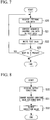
- FIG. 5 is a diagram illustrating an example of a processing flow of the data collection device according to the embodiment of the present invention.
- a flow of an output determination process and a logging process performed by the data collection device 20 will be described with reference to FIG. 5 .
- the data reception unit 21 acquires internal log data in a binary format from the controller 12 (step S10).
- the data reception unit 21 outputs the acquired internal log data to the output determination unit 22.
- the output determination unit 22 reads out the output conditions from the storage unit 24. For example, the output determination unit 22 reads out "the number of motor revolutions" as a parameter to be monitored, "01001110" as a condition value (threshold value 1), and "object to be monitored ⁇ threshold value 1" as a determination method.
- the output determination unit 22 acquires a data position in the internal log data at which binary data corresponding to the parameter to be monitored ("the number of motor revolutions") is stored, with reference to a correspondence relationship between data positions in the internal log data stored in the storage unit 24 and types of parameters allocated to binary data at the positions. For example, "the number of motor revolutions" is a third byte.
- the output determination unit 22 extracts binary data at the data position of the internal log data. For example, in a case where an object to be monitored is "the number of motor revolutions", the output determination unit 22 extracts binary data of the third byte of the internal log data.
- the output determination unit 22 determines whether or not the binary data extracted from the internal log data satisfies the output conditions acquired from the storage unit 24 (step S11). For example, the output determination unit 22 substitutes the value of the extracted binary data or the read-out condition value (threshold value 1) for the determination method "object to be monitored ⁇ threshold value 1" to determine whether or not "the binary data of the third byte of internal log data ⁇ 01001110" is established.
- the output determination unit 22 outputs a signal indicating the establishment of the output conditions to the external output unit 23.
- the external output unit 23 having the acquired signal indicating the establishment of the output conditions outputs a notification signal to an external device through an output port (step S12). For example, in a case where the output port is an external contact output terminal, an on signal is output. In a case where an alarm lamp connected to the external contact output terminal is connected, the alarm lamp is turned on to notify a maintenance worker that internal log data satisfying the output conditions has been detected. In a case where the maintenance worker performs setting such as "determination result indicates an abnormality when the number of motor revolutions is equal to or greater than X", it is possible to know that the number of motor revolutions is equal to or greater than X.
- step S11 In a case where the output conditions are not satisfied (step S11; No) or in a case where the process of step S12 has been completed, the output determination unit 22 adds information of the present time to the internal log data in a binary format which is received from the data reception unit 21 and writes the information in the storage unit 24 (step S13). Thereby, the maintenance worker having noticed the abnormality can confirm the internal log data written in the storage unit 24 and investigate the cause of the abnormality.
- step S14 determines whether or not the next internal log data is output from the air conditioner 10 (step S14). In a case where received data is output (step S14; Yes), the processes from step S10 are repeated. In a case where received data is not output (step S14; No), this processing flow is terminated.
- step S14 may be performed without performing the process of step S13.
- the output determination unit 22 determines that an abnormality has occurred, instructs the external output unit 23 to output a notification signal, and may prompt the maintenance worker to delete the internal log data written in the storage unit 24 and to replace an SD memory card.
- FIG. 6 is a schematic functional block diagram illustrating an example of a data analysis device according to the embodiment of the present invention.
- the data analysis device 30 is, for example, a PC.
- the data analysis device 30 is connected to the data collection device 20 and is used in a case where the setting of output conditions used for the output determination of the output determination unit 22 or a case where the internal log data written in the storage unit 24 is acquired and analyzed.
- the data analysis device 30 includes at least a setting reception unit 31, a log data acquisition unit 32, a data conversion unit 33, and a storage unit 34.
- the data analysis device 30 is communicably connected to the data collection device 20 as necessary.
- the setting reception unit 31 receives a maintenance worker's operation of setting output conditions, and acquires text data including the output conditions.
- the log data acquisition unit 32 acquires internal log data in a binary format which is written in the storage unit 24 of the data collection device 20.
- the data conversion unit 33 converts the internal log data in a binary format which is acquired by the log data acquisition unit 32 into text data.
- the data conversion unit 33 converts a condition value included in the output conditions received by the setting reception unit 31 into a binary format and outputs the converted value to the data collection device 20.
- the storage unit 34 stores, for example, the internal log data converted into text data by the data conversion unit 33, and the like.
- FIG. 7 is a first diagram illustrating an example of a processing flow of the data analysis device according to the embodiment of the present invention.
- a process of acquiring internal log data in a binary format and converting the acquired internal log data into text data in the data analysis device 30 will be described with reference to FIG. 7 .
- the log data acquisition unit 32 acquires the internal log data, having time information attached thereto, which is written in the SD memory card by reading out one line of the internal log data at a time on the basis of a maintenance worker's operation of giving instruction of converting the internal log data (step S20). Next, the log data acquisition unit 32 outputs the acquired internal log data to the data conversion unit 33.
- the data conversion unit 33 converts the acquired internal log data from binary data to text data (step S21).
- a conversion method is as illustrated in FIG. 3 .
- the data conversion unit 33 converts a binary number into a decimal number and then divides the converted number by 0.05 to thereby perform conversion into a physical quantity indicating an outside air temperature.
- the data conversion unit 33 converts a binary number into a decimal number and multiplies the converted number by 20 to thereby perform conversion into a physical quantity indicating the number of motor revolutions.
- pressure of the fourth to fifth bytes the data conversion unit 33 converts a binary number into a decimal number to thereby perform conversion into a physical quantity indicating pressure.
- step S22 the data conversion unit 33 writes the converted text data in the storage unit 34 (step S22).
- step S23 the log data acquisition unit 32 determines whether or not the next internal log data is present. In a case where the next internal log data is present (step S23; Yes), the processes from step S20 are repeated. In a case where the next internal log data is not present (step S23; No), this processing flow is terminated.
- the maintenance worker converts the internal log data in a binary format which is stored in the data collection device 20 into text data to thereby confirm details of the internal log data.
- FIG. 8 is a second diagram illustrating an example of a processing flow of the data analysis device according to the embodiment of the present invention.
- a process of converting a condition value included in output conditions into a binary format and outputting the converted value to the data collection device 20 in the data analysis device 30 will be described with reference to FIG. 8 .
- a maintenance worker sets output conditions.
- the setting reception unit 31 receives an input of the set output conditions (step S30) and outputs the received output conditions to the data conversion unit 33.
- the output conditions include information of a parameter to be monitored, a condition value, and a determination method.
- the condition value which is output to the data conversion unit 33 is text data.
- the data conversion unit 33 converts the acquired condition value into binary data (step S31). For example, in a case where data conversion unit 33 acquires a condition value for an outside air temperature, the data conversion unit 33 converts a value obtained by multiplying the acquired value by 0.05 into a binary number.
- the data conversion unit 33 converts a value obtained by dividing the acquired value by 20 into a binary number. In a case where a condition value for pressure is acquired, the data conversion unit 33 converts the acquired value into a binary number.
- the data conversion unit 33 outputs a new output condition including the converted binary data to the data collection device 20 through communication means such as a LAN (step S32).
- the output condition setting unit 25 acquires a new output condition and updates the output condition stored in the storage unit 24 (memory) to the acquired new output condition.
- condition value is set as binary data so as not to increase the processing cost of the output determination process performed by the data collection device 20.
- Output conditions desired to be detected by the maintenance worker can be set in the data collection device 20.
- the determination of an abnormality is performed on internal log data in a binary format to be output of the air conditioner 10 without converting the data into text data, and thus it is possible to detect an abnormality inside the air conditioner in real time.
- a data collection system configured to include the data collection device 20 and the data analysis device 30, it is possible to set any output conditions and to analyze internal log data.
- a process of each processing in the data collection device 20 and the data analysis device 30 described above is stored in the form of a program in a computer-readable recording medium, and the program is executed by being read out by computers of the data collection device 20 and the data analysis device 30, whereby the above-described processing is performed.
- the computer-readable recording medium refers to a magnetic disk, a magneto-optical disk, a CD-ROM, a DVD-ROM, a semiconductor memory, or the like.
- This computer program is delivered to the computer through a communication line, and the computer having received the program executes the program.
- the program may be a program for realizing a portion of the above-described functions. Further, the program may be a so-called difference file (difference program) which is capable of realizing the above-described functions in combination with a program stored in a computer system in advance.
- the data collection device 20 and the data analysis device 30 may be constituted by one computer, or may be constituted by a plurality of computers that are communicably connected to each other.
Landscapes
- Engineering & Computer Science (AREA)
- Theoretical Computer Science (AREA)
- General Engineering & Computer Science (AREA)
- Quality & Reliability (AREA)
- Physics & Mathematics (AREA)
- General Physics & Mathematics (AREA)
- Chemical & Material Sciences (AREA)
- Combustion & Propulsion (AREA)
- Mechanical Engineering (AREA)
- Computer Hardware Design (AREA)
- Health & Medical Sciences (AREA)
- Biomedical Technology (AREA)
- Computing Systems (AREA)
- Air Conditioning Control Device (AREA)
- Testing And Monitoring For Control Systems (AREA)
Abstract
Description
- The present invention relates to a data collection device of an air conditioner, a data collection system, a control method, and a program.
- Priority is claimed on Japanese Patent Application No.
2014-256037 - The logging of internal log data of an air conditioner and the utilization of the data for service have been generally performed. For example, a maintenance worker connects a data logger for an air conditioner to the air conditioner, and makes the internal log data of the air conditioner written in a storage unit included in the data logger. The maintenance worker connects a PC to the data logger, transmits the internal log data accumulated in the storage unit of the data logger to the PC, and analyzes the internal log data to thereby utilize the presence or absence and cause of an abnormality for an examination.
- In addition, PTL1 as the related art discloses a general-purpose data logger that instructs a PC connected to the device to execute a specific program, which is suitable for a preset specific condition, when receiving a signal satisfying the condition.
- [PTL1] Japanese Unexamined Patent Application, First Publication No.
H11-296556 - However, there is a problem in that the data logger for an air conditioner of the related art cannot report the detection of an abnormality in real time even when the internal log data acquired from the air conditioner includes an abnormal value. Although the data logger disclosed in
PTL 1 can report an abnormal value in real time, it is premised that the data logger is connected to a PC at all times. Accordingly, it is difficult to use the data logger as a data logger for an air conditioner. - The present invention provides a data collection device, a data collection system, a control method, and a program which are capable of solving the above-described problem.
- According to a first aspect of the present invention, there is provided a data collection device including a data reception unit that is connected to an air conditioner and acquires internal log data in a binary format from a controller of the air conditioner, an output determination unit that compares a condition value which is set in a binary format in advance with the acquired internal log data to thereby determine whether or not an output condition is satisfied, and an external output unit that outputs a notification signal in a case where the output determination unit determines that the output condition is satisfied.
- According to a second aspect of the present invention, the output determination unit may extract data corresponding to a parameter to be monitored from the internal log data acquired by the data reception unit, on the basis of a correspondence relationship between a data position in the internal log data which is determined in advance and a kind of parameter allocated to data at the position, and may compare the extracted data with the condition value.
- According to a third aspect of the present invention, there is provided a data collection system including the data collection device according to
claim - According to a fourth aspect of the present invention, the data analysis device may further include a setting reception unit that receives an input of the output condition, and a data conversion unit that converts a condition value included in the output condition into a binary format, and outputs the output condition to the data collection device, and the data collection device may further include an output condition setting unit that acquires the output condition which is output by the data conversion unit and writes the acquired output condition in the storage unit.
- According to a fifth aspect of the present invention, there is provided a control method including causing a data collection device connected to an air conditioner to acquire internal log data in a binary format from a controller of the air conditioner, to compare a condition value which is set in a binary format in advance with the acquired internal log data to thereby determine whether or not an output condition is satisfied, and to output a notification signal in a case where it is determined that the output condition is satisfied.
- According to a sixth aspect of the present invention, there is provided a program causing a computer of a data collection device to function as means, which is connected to an air conditioner, for acquiring internal log data in a binary format from a controller of the air conditioner, means for comparing a condition value which is set in a binary format in advance with the acquired internal log data to thereby determine whether or not an output condition is satisfied, and means for outputting a notification signal in a case where the output condition is satisfied.
- According to the above-described data collection device, data collection system, control method, and program, it is possible to detect an abnormality inside an air conditioner in real time.
-
-
FIG. 1 is a schematic diagram illustrating an example of a data collection device connected to an air conditioner according to an embodiment of the present invention. -
FIG. 2 is a schematic functional block diagram illustrating an example of the data collection device according to the embodiment of the present invention. -
FIG. 3 is a diagram illustrating an example of internal log data according to the embodiment of the present invention. -
FIG. 4A is a first diagram illustrating an example of output conditions according to the embodiment of the present invention. -
FIG. 4B is a second diagram illustrating an example of output conditions according to the embodiment of the present invention. -
FIG. 4C is a third diagram illustrating an example of output conditions according to the embodiment of the present invention. -
FIG. 4D is a fourth diagram illustrating an example of output conditions according to the embodiment of the present invention. -
FIG. 5 is a diagram illustrating an example of a processing flow of the data collection device according to the embodiment of the present invention. -
FIG. 6 is a schematic functional block diagram illustrating an example of a data analysis device according to the embodiment of the present invention. -
FIG. 7 is a first diagram illustrating an example of a processing flow of the data analysis device according to the embodiment of the present invention. -
FIG. 8 is a second diagram illustrating an example of a processing flow of the data analysis device according to the embodiment of the present invention. Description of Embodiments - Hereinafter, a data collection device according to an embodiment of the present invention will be described with reference to
FIGS. 1 to 8 . -
FIG. 1 is a schematic diagram illustrating an example of a data collection device connected to an air conditioner according to an embodiment of the present invention. - In
FIG. 1 , an air conditioner (outdoor unit) 10 is provided with acontroller 12. Thecontroller 12 collects internal log data of theair conditioner 10 and controls the air conditioner. The internal log data refers to data indicating the internal state of theair conditioner 10 which is necessary for the control and monitoring of theair conditioner 10. The internal log data refers to detection information such as outside air temperature, the pressure of a refrigerant gas, the temperature of a compressor or a heat exchanger, the number of motor revolutions, and the like. Theair conditioner 10 is provided with anexternal interface 11 capable of performing data communication with an external device. The internal log data collected by thecontroller 12 can be output to the external device through theexternal interface 11. Theexternal interface 11 is based on, for example, RS232-C. Theexternal interface 11 is generally included in theair conditioner 10, and is used to be connected to a monitoring system, a PC, a data logger, and the like. In this embodiment, thedata collection device 20 is connected to theexternal interface 11, collects internal log data of theair conditioner 10, and monitors an abnormality of theair conditioner 10. - The
data collection device 20, which is connected to theair conditioner 10, is a device for collecting the internal log data of theair conditioner 10, monitoring an abnormality, and the like. Thedata collection device 20 is operated to an external power supply, not shown in the drawing, which is separate from theair conditioner 10. Thedata collection device 20 is a device which is detachable from and independent of theair conditioner 10. Thedata collection device 20 includes an external interface based on, for example, RS232-C as an input port. Thedata collection device 20 acquires internal log data from thecontroller 12 of theair conditioner 10 through the input port. Thedata collection device 20 determines the acquired internal log data on the basis of a preset output determination condition for a notification signal during the detection of an abnormality. Thedata collection device 20 outputs a notification signal indicating that an abnormality has been detected in a case where the internal log data satisfies the output conditions. Thedata collection device 20 includes an output port such as an external contact output terminal, and output an on signal when the internal log data satisfies the output conditions. For example, the output port and anexternal alarm device 300, for example, an alarm lamp are connected to each other, and thus thedata collection device 20 can turn on theexternal alarm device 300 when detecting an abnormality and can notify a maintenance worker or the like of the abnormality in real time. Theexternal alarm device 300 operates, for example, anexternal power supply 200, which is separate from theair conditioner 10, as a power supply. - The
data collection device 20 can store the internal log data acquired from thecontroller 12 in a storage unit. Thedata collection device 20 includes an output port such as a local area network (LAN). When thedata collection device 20 and a PC (data analysis device 30 to be described later) are connected to each other through the LAN, the maintenance worker can confirm a log of the internal log data stored by thedata collection device 20 by using the PC. - Since the occurrence of an abnormality can be confirmed in real time by an alarm of the
external alarm device 300, the maintenance worker can rapidly cope with maintenance service. Since the PC is not necessary for the ascertainment of occurrence of an abnormality, convenience is improved. The PC is connected to thedata collection device 20 at the time of the occurrence of an abnormality so that it is possible to confirm the internal log data before and after the occurrence of the abnormality which is stored in thedata collection device 20, and thus it is possible to examine a cause of the occurrence of the abnormality. -
FIG. 2 is a schematic functional block diagram illustrating an example of the data collection device according to the embodiment of the present invention. - The
data collection device 20 is, for example, a microcomputer, and includes at least adata reception unit 21, anoutput determination unit 22, anexternal output unit 23, astorage unit 24, and an outputcondition setting unit 25 as illustrated inFIG. 2 . Thedata collection device 20 is communicably connected to thecontroller 12 of theair conditioner 10. - The
data reception unit 21 acquires internal log data of theair conditioner 10 from thecontroller 12. The internal log data is given as data in a binary format. - The
output determination unit 22 compares a condition value which is set in a binary format in advance and the acquired internal log data in a binary format with each other to determine whether or not an output condition of a notification signal for giving notice of the detection of an abnormality is satisfied. - The
external output unit 23 outputs the notification signal for giving notice of the detection of an abnormality in a case where theoutput determination unit 22 determines that the output condition is satisfied. - The
storage unit 24 stores the internal log data in a binary format which is acquired by thedata reception unit 21, the condition value used for the determination of output, and the like. Thestorage unit 24 is, for example, a flash memory, a secure digital (SD) memory card, or the like. - The output
condition setting unit 25 acquires an output condition and writes the acquired output condition in thestorage unit 24. -
FIG. 3 is a diagram illustrating an example of internal log data according to the embodiment of the present invention. - For convenience of description, each of pieces of
data 41 to 45 is written by being sectioned by each byte, but is a certain group of internal log data. The pieces of internal log data illustrated inFIG. 3 are configured so as to be arranged in order from data written on the drawing in such a manner that thedata 42 follows thedata 41 and thedata 43 follows thedata 42. As illustrated inFIG. 3 , the internal log data is given as data in a binary format, and is given meaning in units of one byte. - For example, the pieces of
data data 41 is allocated to a value of the tens place of the outside air temperature, and thedata 42 is allocated to a value of the ones place of the outside air temperature. In this embodiment, for example, values obtained by converting values of respective digits of 25°C into binary numbers are not allocated to thedata data - For example, the
data 43 is data allocated to represent the number of revolutions of the motor included in theair conditioner 10. In a case of the number of revolutions of the motor, the value of thedata 43 is converted into a physical quantity indicating the number of revolutions of the motor by converting the binary number into a decimal number and multiplying the converted value by 20. - For example, the pieces of
data data 44 is allocated to a value of the tens place of the pressure, and thedata 45 is allocated to a value of the ones place of the pressure. In order to convert the value of each of the pieces ofdata data -
FIG. 3 illustrates an example of internal log data, but is not limited thereto. For example, the internal log data may be data configured such that a parameter of theair conditioner 10 other than the parameters illustrated here is further added. It is assumed that a data format specifying a correspondence relationship between a data position (which byte) in these internal log data and a parameter allocated to binary data at the position is determined in advance and is recorded in thestorage unit 24. Theoutput determination unit 22 acquires a data position at which data corresponding to a condition value for performing output determination is stored with reference to the correspondence relationship, and extracts data to be determined from the data position of the internal log data acquired by thedata reception unit 21. Here, theoutput determination unit 22 performs the output determination by comparing the extracted binary data and a condition value which is set in a binary format in advance with each other without converting the extracted binary data into a physical quantity indicated by text data in accordance with the conversion rule illustrated above. - The amount of internal log data acquired from the
air conditioner 10 is massive. When the output determination is performed while performing conversion into text data by calculation such as the internal log data in a binary format being converted into a decimal number and being multiplied by 0.05, it takes time to perform the conversion process, and thus there is a possibility that an output determination process is delayed. An attempt to realize real-time abnormality detection while performing the conversion process to text data requires high performance hardware for thedata collection device 20, results in an increase in the size of thedata collection device 20, and causes a problem such as an installation location, which leads to an increase in costs. Consequently, thedata collection device 20 of this embodiment performs the processing in a state of data in a binary format without converting the data into text data. -
FIG. 4A is a first diagram illustrating an example of output conditions according to the embodiment of the present invention.FIG. 4B is a second diagram illustrating an example of output conditions according to the embodiment of the present invention.FIG. 4C is a third diagram illustrating an example of output conditions according to the embodiment of the present invention.FIG. 4D is a fourth diagram illustrating an example of output conditions according to the embodiment of the present invention. - As illustrated in
FIGS. 4A to 4D , the output conditions include items of, for example, "object to be monitored", "threshold value 1", "threshold value 2", and "determination method". The output conditions which are set using a PC are set in the form of a table having these items stored in thestorage unit 24. - In the "object to be monitored", a kind of parameter to be monitored (for example, the number of motor revolutions) is set. In the "
threshold value 1" and the "threshold value 2", condition values used for determination are set. Two items for setting a condition value are provided because the items are used for the determination of a range. As described above, the condition value is stored in thestorage unit 24 in a binary format. Regarding the condition value, a physical quantity represented by text data which is set by a maintenance worker or the like in a PC connected to thedata collection device 20 is converted into a binary format through conversion opposite to the above-described conversion, and is stored in thestorage unit 24. In the "determination method", a determination method using signs of equality and inequality is set. By the setting of theses output conditions, it is possible to perform various determination such as when the value of internal log data is set to be X, is set to be equal to or greater than X, or is in a range between a value of X1 and a value of X2. -
FIG. 4A illustrates a setting example in a case where it is determined that the output conditions are satisfied when a certain object to be monitored is set to be equal to or greater than thethreshold value 1. In a case of this setting, theoutput determination unit 22 compares a value (third byte in the internal log data illustrated inFIG. 3 ) of the number of motor revolutions included in internal log data with "01001110", and determines that the output conditions are satisfied when the number of motor revolutions of the internal log data≥01001110. -
FIG. 4B illustrates a setting example in a case where it is determined that the output conditions are satisfied when a certain object to be monitored is set to be equal to acertain threshold value 1. In a case of this setting, theoutput determination unit 22 compares a value of the number of motor revolutions included in internal log data with "01001110", and determines that the output conditions are satisfied when the number of motor revolutions of the internal log data=01001110. -
FIG. 4C illustrates a setting example in a case where it is determined that the output conditions are satisfied when a certain object to be monitored is set to be a value in a certain range (of thethreshold value 1 to the threshold value 2). In a case of this setting, theoutput determination unit 22 compares a value of the number of motor revolutions included in internal log data with "01001110" and "01011110", and determines that the output conditions are satisfied when 01001110<the number of motor revolutions of the internal log data<01011110. -
FIG. 4D illustrates a setting example in a case where it is determined that the output conditions are satisfied when a certain object to be monitored is set to be equal to or less than thethreshold value 1. In a case of this setting, theoutput determination unit 22 compares a value of the number of motor revolutions included in internal log data with "01011110", and determines that the output conditions are satisfied when the number of motor revolutions of the internal log data ≤ 01011110. - In this manner, the
output determination unit 22 can compare the pieces of binary data with each other by the condition values being set in thestorage unit 24 in binary formats, and thus it is possible to obtain effects such as a reduction in a processing load and an increase in the speed of processing. -
FIG. 5 is a diagram illustrating an example of a processing flow of the data collection device according to the embodiment of the present invention. - A flow of an output determination process and a logging process performed by the
data collection device 20 will be described with reference toFIG. 5 . - It is premised that the output condition as illustrated in
FIGS. 4A to 4D are set in thestorage unit 24 of thedata collection device 20. It is assumed that thedata collection device 20 is connected to theexternal interface 11 provided in theair conditioner 10 through a connector and thecontroller 12 outputs internal log data to thedata collection device 20 through the external interface. - First, the
data reception unit 21 acquires internal log data in a binary format from the controller 12 (step S10). Thedata reception unit 21 outputs the acquired internal log data to theoutput determination unit 22. Next, theoutput determination unit 22 reads out the output conditions from thestorage unit 24. For example, theoutput determination unit 22 reads out "the number of motor revolutions" as a parameter to be monitored, "01001110" as a condition value (threshold value 1), and "object to be monitored ≥threshold value 1" as a determination method. Next, theoutput determination unit 22 acquires a data position in the internal log data at which binary data corresponding to the parameter to be monitored ("the number of motor revolutions") is stored, with reference to a correspondence relationship between data positions in the internal log data stored in thestorage unit 24 and types of parameters allocated to binary data at the positions. For example, "the number of motor revolutions" is a third byte. Next, theoutput determination unit 22 extracts binary data at the data position of the internal log data. For example, in a case where an object to be monitored is "the number of motor revolutions", theoutput determination unit 22 extracts binary data of the third byte of the internal log data. - Next, the
output determination unit 22 determines whether or not the binary data extracted from the internal log data satisfies the output conditions acquired from the storage unit 24 (step S11). For example, theoutput determination unit 22 substitutes the value of the extracted binary data or the read-out condition value (threshold value 1) for the determination method "object to be monitored ≥threshold value 1" to determine whether or not "the binary data of the third byte of internal log data≥01001110" is established. - In a case where the output conditions are satisfied (step S11; Yes), the
output determination unit 22 outputs a signal indicating the establishment of the output conditions to theexternal output unit 23. Theexternal output unit 23 having the acquired signal indicating the establishment of the output conditions outputs a notification signal to an external device through an output port (step S12). For example, in a case where the output port is an external contact output terminal, an on signal is output. In a case where an alarm lamp connected to the external contact output terminal is connected, the alarm lamp is turned on to notify a maintenance worker that internal log data satisfying the output conditions has been detected. In a case where the maintenance worker performs setting such as "determination result indicates an abnormality when the number of motor revolutions is equal to or greater than X", it is possible to know that the number of motor revolutions is equal to or greater than X. - In a case where the output conditions are not satisfied (step S11; No) or in a case where the process of step S12 has been completed, the
output determination unit 22 adds information of the present time to the internal log data in a binary format which is received from thedata reception unit 21 and writes the information in the storage unit 24 (step S13). Thereby, the maintenance worker having noticed the abnormality can confirm the internal log data written in thestorage unit 24 and investigate the cause of the abnormality. - Next, the
data reception unit 21 determines whether or not the next internal log data is output from the air conditioner 10 (step S14). In a case where received data is output (step S14; Yes), the processes from step S10 are repeated. In a case where received data is not output (step S14; No), this processing flow is terminated. - In a case where the storage capacity of the
storage unit 24 is not sufficient in writing the internal log data received from theair conditioner 10 in thestorage unit 24 in step S13, the process of step S14 may be performed without performing the process of step S13. When the writing cannot be performed due to the insufficient storage capacity of thestorage unit 24, theoutput determination unit 22 determines that an abnormality has occurred, instructs theexternal output unit 23 to output a notification signal, and may prompt the maintenance worker to delete the internal log data written in thestorage unit 24 and to replace an SD memory card. -
FIG. 6 is a schematic functional block diagram illustrating an example of a data analysis device according to the embodiment of the present invention. - In
FIG. 6 , thedata analysis device 30 is, for example, a PC. Thedata analysis device 30 is connected to thedata collection device 20 and is used in a case where the setting of output conditions used for the output determination of theoutput determination unit 22 or a case where the internal log data written in thestorage unit 24 is acquired and analyzed. - As illustrated in
FIG. 6 , thedata analysis device 30 includes at least asetting reception unit 31, a logdata acquisition unit 32, adata conversion unit 33, and astorage unit 34. Thedata analysis device 30 is communicably connected to thedata collection device 20 as necessary. - The
setting reception unit 31 receives a maintenance worker's operation of setting output conditions, and acquires text data including the output conditions. - The log
data acquisition unit 32 acquires internal log data in a binary format which is written in thestorage unit 24 of thedata collection device 20. - The
data conversion unit 33 converts the internal log data in a binary format which is acquired by the logdata acquisition unit 32 into text data. Thedata conversion unit 33 converts a condition value included in the output conditions received by thesetting reception unit 31 into a binary format and outputs the converted value to thedata collection device 20. - The
storage unit 34 stores, for example, the internal log data converted into text data by thedata conversion unit 33, and the like. -
FIG. 7 is a first diagram illustrating an example of a processing flow of the data analysis device according to the embodiment of the present invention. - A process of acquiring internal log data in a binary format and converting the acquired internal log data into text data in the
data analysis device 30 will be described with reference toFIG. 7 . - It is premised that the internal log data is recorded in an SD memory card and the SD memory card is mounted on the
data analysis device 30. - First, the log
data acquisition unit 32 acquires the internal log data, having time information attached thereto, which is written in the SD memory card by reading out one line of the internal log data at a time on the basis of a maintenance worker's operation of giving instruction of converting the internal log data (step S20). Next, the logdata acquisition unit 32 outputs the acquired internal log data to thedata conversion unit 33. - Next, the
data conversion unit 33 converts the acquired internal log data from binary data to text data (step S21). A conversion method is as illustrated inFIG. 3 . For example, regarding outside air temperature data of the first to second bytes of the internal log data, thedata conversion unit 33 converts a binary number into a decimal number and then divides the converted number by 0.05 to thereby perform conversion into a physical quantity indicating an outside air temperature. In a case of the number of motor revolutions of the third byte, thedata conversion unit 33 converts a binary number into a decimal number and multiplies the converted number by 20 to thereby perform conversion into a physical quantity indicating the number of motor revolutions. In a case of pressure of the fourth to fifth bytes, thedata conversion unit 33 converts a binary number into a decimal number to thereby perform conversion into a physical quantity indicating pressure. - Next, the
data conversion unit 33 writes the converted text data in the storage unit 34 (step S22). Next, the logdata acquisition unit 32 determines whether or not the next internal log data is present (step S23). In a case where the next internal log data is present (step S23; Yes), the processes from step S20 are repeated. In a case where the next internal log data is not present (step S23; No), this processing flow is terminated. - Thereby, the maintenance worker converts the internal log data in a binary format which is stored in the
data collection device 20 into text data to thereby confirm details of the internal log data. - In the above description, a case where internal log data stored in the
data collection device 20 is acquired by mounting an SD memory card has been described as an example. However, thedata collection device 20 and thedata analysis device 30 may be connected to each other through communication means such as a LAN, and internal log data stored in thedata collection device 20 may be transmitted to thedata analysis device 30 and may be written in thestorage unit 34. -
FIG. 8 is a second diagram illustrating an example of a processing flow of the data analysis device according to the embodiment of the present invention. - A process of converting a condition value included in output conditions into a binary format and outputting the converted value to the
data collection device 20 in thedata analysis device 30 will be described with reference toFIG. 8 . - It is premised that the
data analysis device 30 and thedata collection device 20 are communicably connected to each other. - First, a maintenance worker sets output conditions. Then, the
setting reception unit 31 receives an input of the set output conditions (step S30) and outputs the received output conditions to thedata conversion unit 33. The output conditions include information of a parameter to be monitored, a condition value, and a determination method. At this time, the condition value which is output to thedata conversion unit 33 is text data. Next, thedata conversion unit 33 converts the acquired condition value into binary data (step S31). For example, in a case wheredata conversion unit 33 acquires a condition value for an outside air temperature, thedata conversion unit 33 converts a value obtained by multiplying the acquired value by 0.05 into a binary number. In a case where a condition value for the number of motor revolutions is acquired, thedata conversion unit 33 converts a value obtained by dividing the acquired value by 20 into a binary number. In a case where a condition value for pressure is acquired, thedata conversion unit 33 converts the acquired value into a binary number. Thedata conversion unit 33 outputs a new output condition including the converted binary data to thedata collection device 20 through communication means such as a LAN (step S32). In thedata collection device 20, the outputcondition setting unit 25 acquires a new output condition and updates the output condition stored in the storage unit 24 (memory) to the acquired new output condition. - Thereby, it is possible to set the condition value as binary data so as not to increase the processing cost of the output determination process performed by the
data collection device 20. Output conditions desired to be detected by the maintenance worker can be set in thedata collection device 20. - According to the
data collection device 20 of this embodiment, the determination of an abnormality is performed on internal log data in a binary format to be output of theair conditioner 10 without converting the data into text data, and thus it is possible to detect an abnormality inside the air conditioner in real time. - According to a data collection system configured to include the
data collection device 20 and thedata analysis device 30, it is possible to set any output conditions and to analyze internal log data. - A process of each processing in the
data collection device 20 and thedata analysis device 30 described above is stored in the form of a program in a computer-readable recording medium, and the program is executed by being read out by computers of thedata collection device 20 and thedata analysis device 30, whereby the above-described processing is performed. Here, the computer-readable recording medium refers to a magnetic disk, a magneto-optical disk, a CD-ROM, a DVD-ROM, a semiconductor memory, or the like. This computer program is delivered to the computer through a communication line, and the computer having received the program executes the program. - The program may be a program for realizing a portion of the above-described functions. Further, the program may be a so-called difference file (difference program) which is capable of realizing the above-described functions in combination with a program stored in a computer system in advance. The
data collection device 20 and thedata analysis device 30 may be constituted by one computer, or may be constituted by a plurality of computers that are communicably connected to each other. - In addition, the components in the above-described embodiment can be appropriately replaced with well-known components without departing from the scope of the present invention. The technical scope of the invention is not limited to the above-described embodiment, and various modifications can be made without departing from the scope of the present invention.
- According to the above-described data collection device, data collection system, control method, and program, it is possible to detect an abnormality inside an air conditioner in real time.
-
- 10:
- AIR CONDITIONER
- 11:
- EXTERNAL INTERFACE
- 12:
- CONTROLLER
- 20:
- DATA COLLECTION DEVICE
- 21:
- DATA RECEPTION UNIT
- 22:
- OUTPUT DETERMINATION UNIT
- 23:
- EXTERNAL OUTPUT UNIT
- 24:
- STORAGE UNIT
- 25:
- OUTPUT CONDITION SETTING UNIT
- 30:
- DATAANALYSIS DEVICE
- 31:
- SETTING RECEPTION UNIT
- 32:
- LOG DATA ACQUISITION UNIT
- 33:
- DATA CONVERSION UNIT
- 34:
- STORAGE UNIT
Claims (6)
- A data collection device comprising:a data reception unit that is connected to an air conditioner and acquires internal log data in a binary format from a controller of the air conditioner;an output determination unit that compares a condition value which is set in a binary format in advance with the acquired internal log data to thereby determine whether or not an output condition is satisfied; andan external output unit that outputs a notification signal in a case where the output determination unit determines that the output condition is satisfied.
- The data collection device according to claim 1,
wherein the output determination unit extracts data corresponding to a parameter to be monitored from the internal log data acquired by the data reception unit, on the basis of a correspondence relationship between a data position in the internal log data which is determined in advance and a kind of parameter allocated to data at the position, and compares the extracted data with the condition value. - A data collection system comprising:the data collection device according to claim 1 or 2; anda data analysis device that is detachably connected to the data collection device,wherein the data collection device further includes a storage unit that stores the internal log data acquired by the data reception unit, andwherein the data analysis device includesa log data acquisition unit that acquires the internal log data written in the storage unit of the data collection device, anda conversion unit that converts the internal log data acquired by the log data acquisition unit into text data.
- The data collection system according to claim 3,
wherein the data analysis device further includes
a setting reception unit that receives an input of the output condition, and
a data conversion unit that converts a condition value included in the output condition into a binary format, and outputs the output condition to the data collection device, wherein
the data collection device further includes an output condition setting unit that acquires the output condition which is output by the data conversion unit and writes the acquired output condition in the storage unit. - A control method comprising:causing a data collection device connected to an air conditioner to acquire internal log data in a binary format from a controller of the air conditioner, to compare a condition value which is set in a binary format in advance with the acquired internal log data to thereby determine whether or not an output condition is satisfied, and to output a notification signal in a case where it is determined that the output condition is satisfied.
- A program causing a computer of a data collection device to function as:means, which is connected to an air conditioner, for acquiring internal log data in a binary format from a controller of the air conditioner;means for comparing a condition value which is set in a binary format in advance with the acquired internal log data to thereby determine whether or not an output condition is satisfied; andmeans for outputting a notification signal in a case where the output condition is satisfied.
Applications Claiming Priority (2)
| Application Number | Priority Date | Filing Date | Title |
|---|---|---|---|
| JP2014256037A JP6550636B2 (en) | 2014-12-18 | 2014-12-18 | Data acquisition device, data acquisition system, control method and program |
| PCT/JP2015/083021 WO2016098540A1 (en) | 2014-12-18 | 2015-11-25 | Data collection device, data collection system, control method, and program |
Publications (3)
| Publication Number | Publication Date |
|---|---|
| EP3220271A1 true EP3220271A1 (en) | 2017-09-20 |
| EP3220271A4 EP3220271A4 (en) | 2018-01-03 |
| EP3220271B1 EP3220271B1 (en) | 2019-01-30 |
Family
ID=56126438
Family Applications (1)
| Application Number | Title | Priority Date | Filing Date |
|---|---|---|---|
| EP15869748.2A Not-in-force EP3220271B1 (en) | 2014-12-18 | 2015-11-25 | Data collection device, data collection system, control method, and program |
Country Status (4)
| Country | Link |
|---|---|
| EP (1) | EP3220271B1 (en) |
| JP (1) | JP6550636B2 (en) |
| CN (1) | CN107111543A (en) |
| WO (1) | WO2016098540A1 (en) |
Cited By (1)
| Publication number | Priority date | Publication date | Assignee | Title |
|---|---|---|---|---|
| EP3726157A4 (en) * | 2017-12-13 | 2021-01-27 | Daikin Industries, Ltd. | AIR CONDITIONING SYSTEM, REMOTE CONTROL DEVICE AND PROCESS FOR RECORDING HISTORY OF OPERATING DATA OF AN AIR CONDITIONER |
Families Citing this family (6)
| Publication number | Priority date | Publication date | Assignee | Title |
|---|---|---|---|---|
| EP4528174A3 (en) * | 2017-04-06 | 2025-06-11 | Carrier Corporation | Moderate-to-low global warming potential value refrigerant leak detection |
| JP6683385B1 (en) * | 2018-11-15 | 2020-04-22 | Necプラットフォームズ株式会社 | Information processing apparatus, information processing system, automatic text conversion method, and automatic text conversion program |
| JP6951017B2 (en) * | 2018-12-25 | 2021-10-20 | Necプラットフォームズ株式会社 | Log acquisition device, log data acquisition method and log data acquisition program |
| CN113826052B (en) * | 2019-04-25 | 2023-01-31 | 三菱电机株式会社 | Data collection device, data collection method, and computer-readable non-transitory recording medium |
| JP7148088B2 (en) * | 2020-02-28 | 2022-10-05 | オリオン機械株式会社 | adjuster |
| JP7072625B1 (en) | 2020-11-26 | 2022-05-20 | 任天堂株式会社 | Game development system |
Family Cites Families (11)
| Publication number | Priority date | Publication date | Assignee | Title |
|---|---|---|---|---|
| JPS6191736A (en) * | 1984-10-11 | 1986-05-09 | Nec Corp | Editing and outputting system for main storage history information |
| JP3119046B2 (en) * | 1993-09-01 | 2000-12-18 | ダイキン工業株式会社 | Air conditioner condition monitoring device |
| JPH08212112A (en) * | 1994-12-06 | 1996-08-20 | Mitsubishi Electric Corp | Data processing method |
| JP2000163122A (en) * | 1998-11-30 | 2000-06-16 | Toshiba Corp | Computer-managed data management system for monitoring and control |
| JP2009134699A (en) * | 2007-10-31 | 2009-06-18 | Daikin Ind Ltd | Data collection device and data management system |
| JP2011141081A (en) * | 2010-01-07 | 2011-07-21 | Mitsubishi Heavy Ind Ltd | Air-conditioning monitoring system, its control method, air conditioner, and centralized monitoring device |
| JP2012122668A (en) * | 2010-12-08 | 2012-06-28 | Mitsubishi Heavy Ind Ltd | Air conditioner |
| JP5747655B2 (en) * | 2011-05-24 | 2015-07-15 | 株式会社リコー | Image forming apparatus, information processing apparatus, program |
| JP5884125B2 (en) * | 2012-02-07 | 2016-03-15 | ナガノサイエンス株式会社 | Anomaly detection apparatus and environmental test apparatus equipped with the same |
| JP5930803B2 (en) * | 2012-03-30 | 2016-06-08 | 日立アプライアンス株式会社 | Air conditioning control system and air conditioning control method |
| WO2014115316A1 (en) * | 2013-01-25 | 2014-07-31 | 三菱電機株式会社 | Air-conditioning system |
-
2014
- 2014-12-18 JP JP2014256037A patent/JP6550636B2/en active Active
-
2015
- 2015-11-25 CN CN201580068045.5A patent/CN107111543A/en active Pending
- 2015-11-25 EP EP15869748.2A patent/EP3220271B1/en not_active Not-in-force
- 2015-11-25 WO PCT/JP2015/083021 patent/WO2016098540A1/en not_active Ceased
Cited By (2)
| Publication number | Priority date | Publication date | Assignee | Title |
|---|---|---|---|---|
| EP3726157A4 (en) * | 2017-12-13 | 2021-01-27 | Daikin Industries, Ltd. | AIR CONDITIONING SYSTEM, REMOTE CONTROL DEVICE AND PROCESS FOR RECORDING HISTORY OF OPERATING DATA OF AN AIR CONDITIONER |
| US11649979B2 (en) | 2017-12-13 | 2023-05-16 | Daikin Industries, Ltd. | Air conditioning system, remote controller, and method for saving history of operation data on air conditioner |
Also Published As
| Publication number | Publication date |
|---|---|
| WO2016098540A1 (en) | 2016-06-23 |
| EP3220271B1 (en) | 2019-01-30 |
| CN107111543A (en) | 2017-08-29 |
| JP2016114341A (en) | 2016-06-23 |
| EP3220271A4 (en) | 2018-01-03 |
| JP6550636B2 (en) | 2019-07-31 |
Similar Documents
| Publication | Publication Date | Title |
|---|---|---|
| EP3220271B1 (en) | Data collection device, data collection system, control method, and program | |
| US10257216B2 (en) | Method and system for obtaining and analyzing forensic data in a distributed computer infrastructure | |
| EP3309682B1 (en) | Data collection system and method, and method for reducing the quantity of measurement data | |
| US11480948B2 (en) | Monitoring target selecting device, monitoring target selecting method, and program | |
| CN112069005A (en) | A vehicle CAN communication function detection method | |
| CN106574863A (en) | Power equipment sound diagnosis system | |
| CN113254287B (en) | Health status self-check method, device, equipment and computer readable medium | |
| JP2013168763A (en) | Security monitoring system and security monitoring method | |
| CN102395834B (en) | Air conditioning system diagnostic device | |
| US11237547B2 (en) | Information processing device, information processing method, and program | |
| JP6645643B2 (en) | Data output system, control method and program | |
| CN115111703A (en) | Method, terminal and storage medium for detecting filth blockage of water-cooled air conditioner | |
| CN114647223B (en) | Whole machine behavior diagnosis method, device, controller, wind farm, system and medium | |
| EP3451685A1 (en) | Remote monitoring system, central data collection device, field data collection device, remote monitoring method, and program | |
| EP3448054A1 (en) | Remote monitoring system, central data collection device, field data collection device, remote monitoring method, and program | |
| JP5925078B2 (en) | Remote management system and gateway device | |
| CN110543197B (en) | Method and device for controlling operation of train main transformer | |
| JP5588231B2 (en) | Trend monitoring apparatus and method | |
| CN109470934B (en) | Input phase loss detection method and detection system thereof | |
| US10698395B2 (en) | Air-conditioning apparatus and method of detecting abnormality in transmission line | |
| CN116241368B (en) | Method, device, equipment and storage medium for determining engine oil pressure relief point | |
| CN106791612B (en) | Video display method, system and monitoring video display system of master control terminal | |
| CN119619705A (en) | Cable fault factor determination system and method based on parameter evolution identification | |
| CN118804552A (en) | Communication room terminal air conditioning control method, device, electronic equipment and storage medium | |
| CN117354338A (en) | Heat pump type desiccator fault detection method, device and system |
Legal Events
| Date | Code | Title | Description |
|---|---|---|---|
| STAA | Information on the status of an ep patent application or granted ep patent |
Free format text: STATUS: THE INTERNATIONAL PUBLICATION HAS BEEN MADE |
|
| PUAI | Public reference made under article 153(3) epc to a published international application that has entered the european phase |
Free format text: ORIGINAL CODE: 0009012 |
|
| STAA | Information on the status of an ep patent application or granted ep patent |
Free format text: STATUS: REQUEST FOR EXAMINATION WAS MADE |
|
| 17P | Request for examination filed |
Effective date: 20170613 |
|
| AK | Designated contracting states |
Kind code of ref document: A1 Designated state(s): AL AT BE BG CH CY CZ DE DK EE ES FI FR GB GR HR HU IE IS IT LI LT LU LV MC MK MT NL NO PL PT RO RS SE SI SK SM TR |
|
| AX | Request for extension of the european patent |
Extension state: BA ME |
|
| A4 | Supplementary search report drawn up and despatched |
Effective date: 20171201 |
|
| RIC1 | Information provided on ipc code assigned before grant |
Ipc: G06F 11/07 20060101ALI20171127BHEP Ipc: G06F 11/30 20060101ALI20171127BHEP Ipc: G06F 11/34 20060101ALI20171127BHEP Ipc: F24F 11/00 20180101AFI20171127BHEP |
|
| DAV | Request for validation of the european patent (deleted) | ||
| DAX | Request for extension of the european patent (deleted) | ||
| REG | Reference to a national code |
Ref country code: DE Ref legal event code: R079 Ref document number: 602015024230 Country of ref document: DE Free format text: PREVIOUS MAIN CLASS: G06F0011340000 Ipc: G06F0011070000 |
|
| GRAP | Despatch of communication of intention to grant a patent |
Free format text: ORIGINAL CODE: EPIDOSNIGR1 |
|
| STAA | Information on the status of an ep patent application or granted ep patent |
Free format text: STATUS: GRANT OF PATENT IS INTENDED |
|
| RIC1 | Information provided on ipc code assigned before grant |
Ipc: F24F 11/89 20180101ALI20180725BHEP Ipc: G06F 11/07 20060101AFI20180725BHEP Ipc: F24F 11/30 20180101ALI20180725BHEP Ipc: G06F 11/30 20060101ALI20180725BHEP Ipc: G06F 11/34 20060101ALI20180725BHEP |
|
| INTG | Intention to grant announced |
Effective date: 20180822 |
|
| GRAS | Grant fee paid |
Free format text: ORIGINAL CODE: EPIDOSNIGR3 |
|
| GRAA | (expected) grant |
Free format text: ORIGINAL CODE: 0009210 |
|
| STAA | Information on the status of an ep patent application or granted ep patent |
Free format text: STATUS: THE PATENT HAS BEEN GRANTED |
|
| AK | Designated contracting states |
Kind code of ref document: B1 Designated state(s): AL AT BE BG CH CY CZ DE DK EE ES FI FR GB GR HR HU IE IS IT LI LT LU LV MC MK MT NL NO PL PT RO RS SE SI SK SM TR |
|
| REG | Reference to a national code |
Ref country code: GB Ref legal event code: FG4D |
|
| REG | Reference to a national code |
Ref country code: CH Ref legal event code: EP |
|
| REG | Reference to a national code |
Ref country code: AT Ref legal event code: REF Ref document number: 1093808 Country of ref document: AT Kind code of ref document: T Effective date: 20190215 |
|
| REG | Reference to a national code |
Ref country code: IE Ref legal event code: FG4D |
|
| REG | Reference to a national code |
Ref country code: DE Ref legal event code: R096 Ref document number: 602015024230 Country of ref document: DE |
|
| REG | Reference to a national code |
Ref country code: LT Ref legal event code: MG4D |
|
| REG | Reference to a national code |
Ref country code: NL Ref legal event code: MP Effective date: 20190130 |
|
| PG25 | Lapsed in a contracting state [announced via postgrant information from national office to epo] |
Ref country code: NL Free format text: LAPSE BECAUSE OF FAILURE TO SUBMIT A TRANSLATION OF THE DESCRIPTION OR TO PAY THE FEE WITHIN THE PRESCRIBED TIME-LIMIT Effective date: 20190130 Ref country code: SE Free format text: LAPSE BECAUSE OF FAILURE TO SUBMIT A TRANSLATION OF THE DESCRIPTION OR TO PAY THE FEE WITHIN THE PRESCRIBED TIME-LIMIT Effective date: 20190130 Ref country code: PL Free format text: LAPSE BECAUSE OF FAILURE TO SUBMIT A TRANSLATION OF THE DESCRIPTION OR TO PAY THE FEE WITHIN THE PRESCRIBED TIME-LIMIT Effective date: 20190130 Ref country code: ES Free format text: LAPSE BECAUSE OF FAILURE TO SUBMIT A TRANSLATION OF THE DESCRIPTION OR TO PAY THE FEE WITHIN THE PRESCRIBED TIME-LIMIT Effective date: 20190130 Ref country code: LT Free format text: LAPSE BECAUSE OF FAILURE TO SUBMIT A TRANSLATION OF THE DESCRIPTION OR TO PAY THE FEE WITHIN THE PRESCRIBED TIME-LIMIT Effective date: 20190130 Ref country code: NO Free format text: LAPSE BECAUSE OF FAILURE TO SUBMIT A TRANSLATION OF THE DESCRIPTION OR TO PAY THE FEE WITHIN THE PRESCRIBED TIME-LIMIT Effective date: 20190430 Ref country code: PT Free format text: LAPSE BECAUSE OF FAILURE TO SUBMIT A TRANSLATION OF THE DESCRIPTION OR TO PAY THE FEE WITHIN THE PRESCRIBED TIME-LIMIT Effective date: 20190530 Ref country code: FI Free format text: LAPSE BECAUSE OF FAILURE TO SUBMIT A TRANSLATION OF THE DESCRIPTION OR TO PAY THE FEE WITHIN THE PRESCRIBED TIME-LIMIT Effective date: 20190130 |
|
| REG | Reference to a national code |
Ref country code: AT Ref legal event code: MK05 Ref document number: 1093808 Country of ref document: AT Kind code of ref document: T Effective date: 20190130 |
|
| PG25 | Lapsed in a contracting state [announced via postgrant information from national office to epo] |
Ref country code: IS Free format text: LAPSE BECAUSE OF FAILURE TO SUBMIT A TRANSLATION OF THE DESCRIPTION OR TO PAY THE FEE WITHIN THE PRESCRIBED TIME-LIMIT Effective date: 20190530 Ref country code: BG Free format text: LAPSE BECAUSE OF FAILURE TO SUBMIT A TRANSLATION OF THE DESCRIPTION OR TO PAY THE FEE WITHIN THE PRESCRIBED TIME-LIMIT Effective date: 20190430 Ref country code: RS Free format text: LAPSE BECAUSE OF FAILURE TO SUBMIT A TRANSLATION OF THE DESCRIPTION OR TO PAY THE FEE WITHIN THE PRESCRIBED TIME-LIMIT Effective date: 20190130 Ref country code: HR Free format text: LAPSE BECAUSE OF FAILURE TO SUBMIT A TRANSLATION OF THE DESCRIPTION OR TO PAY THE FEE WITHIN THE PRESCRIBED TIME-LIMIT Effective date: 20190130 Ref country code: LV Free format text: LAPSE BECAUSE OF FAILURE TO SUBMIT A TRANSLATION OF THE DESCRIPTION OR TO PAY THE FEE WITHIN THE PRESCRIBED TIME-LIMIT Effective date: 20190130 Ref country code: GR Free format text: LAPSE BECAUSE OF FAILURE TO SUBMIT A TRANSLATION OF THE DESCRIPTION OR TO PAY THE FEE WITHIN THE PRESCRIBED TIME-LIMIT Effective date: 20190501 |
|
| PG25 | Lapsed in a contracting state [announced via postgrant information from national office to epo] |
Ref country code: AL Free format text: LAPSE BECAUSE OF FAILURE TO SUBMIT A TRANSLATION OF THE DESCRIPTION OR TO PAY THE FEE WITHIN THE PRESCRIBED TIME-LIMIT Effective date: 20190130 Ref country code: CZ Free format text: LAPSE BECAUSE OF FAILURE TO SUBMIT A TRANSLATION OF THE DESCRIPTION OR TO PAY THE FEE WITHIN THE PRESCRIBED TIME-LIMIT Effective date: 20190130 Ref country code: SK Free format text: LAPSE BECAUSE OF FAILURE TO SUBMIT A TRANSLATION OF THE DESCRIPTION OR TO PAY THE FEE WITHIN THE PRESCRIBED TIME-LIMIT Effective date: 20190130 Ref country code: EE Free format text: LAPSE BECAUSE OF FAILURE TO SUBMIT A TRANSLATION OF THE DESCRIPTION OR TO PAY THE FEE WITHIN THE PRESCRIBED TIME-LIMIT Effective date: 20190130 Ref country code: DK Free format text: LAPSE BECAUSE OF FAILURE TO SUBMIT A TRANSLATION OF THE DESCRIPTION OR TO PAY THE FEE WITHIN THE PRESCRIBED TIME-LIMIT Effective date: 20190130 Ref country code: IT Free format text: LAPSE BECAUSE OF FAILURE TO SUBMIT A TRANSLATION OF THE DESCRIPTION OR TO PAY THE FEE WITHIN THE PRESCRIBED TIME-LIMIT Effective date: 20190130 Ref country code: RO Free format text: LAPSE BECAUSE OF FAILURE TO SUBMIT A TRANSLATION OF THE DESCRIPTION OR TO PAY THE FEE WITHIN THE PRESCRIBED TIME-LIMIT Effective date: 20190130 |
|
| REG | Reference to a national code |
Ref country code: DE Ref legal event code: R097 Ref document number: 602015024230 Country of ref document: DE |
|
| PG25 | Lapsed in a contracting state [announced via postgrant information from national office to epo] |
Ref country code: SM Free format text: LAPSE BECAUSE OF FAILURE TO SUBMIT A TRANSLATION OF THE DESCRIPTION OR TO PAY THE FEE WITHIN THE PRESCRIBED TIME-LIMIT Effective date: 20190130 |
|
| PLBE | No opposition filed within time limit |
Free format text: ORIGINAL CODE: 0009261 |
|
| STAA | Information on the status of an ep patent application or granted ep patent |
Free format text: STATUS: NO OPPOSITION FILED WITHIN TIME LIMIT |
|
| PG25 | Lapsed in a contracting state [announced via postgrant information from national office to epo] |
Ref country code: AT Free format text: LAPSE BECAUSE OF FAILURE TO SUBMIT A TRANSLATION OF THE DESCRIPTION OR TO PAY THE FEE WITHIN THE PRESCRIBED TIME-LIMIT Effective date: 20190130 |
|
| 26N | No opposition filed |
Effective date: 20191031 |
|
| PGFP | Annual fee paid to national office [announced via postgrant information from national office to epo] |
Ref country code: DE Payment date: 20191112 Year of fee payment: 5 |
|
| PG25 | Lapsed in a contracting state [announced via postgrant information from national office to epo] |
Ref country code: SI Free format text: LAPSE BECAUSE OF FAILURE TO SUBMIT A TRANSLATION OF THE DESCRIPTION OR TO PAY THE FEE WITHIN THE PRESCRIBED TIME-LIMIT Effective date: 20190130 |
|
| PGFP | Annual fee paid to national office [announced via postgrant information from national office to epo] |
Ref country code: FR Payment date: 20191014 Year of fee payment: 5 |
|
| PG25 | Lapsed in a contracting state [announced via postgrant information from national office to epo] |
Ref country code: TR Free format text: LAPSE BECAUSE OF FAILURE TO SUBMIT A TRANSLATION OF THE DESCRIPTION OR TO PAY THE FEE WITHIN THE PRESCRIBED TIME-LIMIT Effective date: 20190130 |
|
| PGFP | Annual fee paid to national office [announced via postgrant information from national office to epo] |
Ref country code: GB Payment date: 20191122 Year of fee payment: 5 |
|
| REG | Reference to a national code |
Ref country code: CH Ref legal event code: PL |
|
| PG25 | Lapsed in a contracting state [announced via postgrant information from national office to epo] |
Ref country code: LU Free format text: LAPSE BECAUSE OF NON-PAYMENT OF DUE FEES Effective date: 20191125 Ref country code: MC Free format text: LAPSE BECAUSE OF FAILURE TO SUBMIT A TRANSLATION OF THE DESCRIPTION OR TO PAY THE FEE WITHIN THE PRESCRIBED TIME-LIMIT Effective date: 20190130 Ref country code: CH Free format text: LAPSE BECAUSE OF NON-PAYMENT OF DUE FEES Effective date: 20191130 Ref country code: LI Free format text: LAPSE BECAUSE OF NON-PAYMENT OF DUE FEES Effective date: 20191130 |
|
| REG | Reference to a national code |
Ref country code: BE Ref legal event code: MM Effective date: 20191130 |
|
| PG25 | Lapsed in a contracting state [announced via postgrant information from national office to epo] |
Ref country code: IE Free format text: LAPSE BECAUSE OF NON-PAYMENT OF DUE FEES Effective date: 20191125 |
|
| PG25 | Lapsed in a contracting state [announced via postgrant information from national office to epo] |
Ref country code: BE Free format text: LAPSE BECAUSE OF NON-PAYMENT OF DUE FEES Effective date: 20191130 |
|
| PG25 | Lapsed in a contracting state [announced via postgrant information from national office to epo] |
Ref country code: CY Free format text: LAPSE BECAUSE OF FAILURE TO SUBMIT A TRANSLATION OF THE DESCRIPTION OR TO PAY THE FEE WITHIN THE PRESCRIBED TIME-LIMIT Effective date: 20190130 |
|
| REG | Reference to a national code |
Ref country code: DE Ref legal event code: R119 Ref document number: 602015024230 Country of ref document: DE |
|
| GBPC | Gb: european patent ceased through non-payment of renewal fee |
Effective date: 20201125 |
|
| PG25 | Lapsed in a contracting state [announced via postgrant information from national office to epo] |
Ref country code: HU Free format text: LAPSE BECAUSE OF FAILURE TO SUBMIT A TRANSLATION OF THE DESCRIPTION OR TO PAY THE FEE WITHIN THE PRESCRIBED TIME-LIMIT; INVALID AB INITIO Effective date: 20151125 Ref country code: MT Free format text: LAPSE BECAUSE OF FAILURE TO SUBMIT A TRANSLATION OF THE DESCRIPTION OR TO PAY THE FEE WITHIN THE PRESCRIBED TIME-LIMIT Effective date: 20190130 |
|
| PG25 | Lapsed in a contracting state [announced via postgrant information from national office to epo] |
Ref country code: FR Free format text: LAPSE BECAUSE OF NON-PAYMENT OF DUE FEES Effective date: 20201130 |
|
| PG25 | Lapsed in a contracting state [announced via postgrant information from national office to epo] |
Ref country code: DE Free format text: LAPSE BECAUSE OF NON-PAYMENT OF DUE FEES Effective date: 20210601 Ref country code: GB Free format text: LAPSE BECAUSE OF NON-PAYMENT OF DUE FEES Effective date: 20201125 |
|
| PG25 | Lapsed in a contracting state [announced via postgrant information from national office to epo] |
Ref country code: MK Free format text: LAPSE BECAUSE OF FAILURE TO SUBMIT A TRANSLATION OF THE DESCRIPTION OR TO PAY THE FEE WITHIN THE PRESCRIBED TIME-LIMIT Effective date: 20190130 |